Hangzhou Hikvision Digital Technology 19ABNG Network Security Control Panel User Manual
Hangzhou Hikvision Digital Technology Co., Ltd. Network Security Control Panel Users Manual
Users Manual

Control Panel User Manual
0
UD.6L0206D1097A01
Network Security Control Panel
User Manual

Control Panel User Manual
1
User Manual
COPYRIGHT © 2015 Hangzhou Hikvision Digital Technology Co., Ltd.
ALL RIGHTS RESERVED.
Any and all information, including, among others, wordings, pictures, graphs are the properties
of Hangzhou Hikvision Digital Technology Co., Ltd. or its subsidiaries (hereinafter referred to be
“Hikvision”). This user manual (hereinafter referred to be “the Manual”) cannot be reproduced,
changed, translated, or distributed, partially or wholly, by any means, without the prior written
permission of Hikvision. Unless otherwise stipulated, Hikvision does not make any warranties,
guarantees or representations, express or implied, regarding to the Manual.

Control Panel User Manual
2
About this Manual
This Manual is applicable to Control Panel
The Manual includes instructions for using and managing the product. Pictures, charts, images
and all other information hereinafter are for description and explanation only. The information
contained in the Manual is subject to change, without notice, due to firmware updates or other
reasons. Please find the latest version in the company website
(http://overseas.hikvision.com/en/).
Please use this user manual under the guidance of professionals.
Trademarks Acknowledgement
and other Hikvision’s trademarks and logos are the properties of Hikvision in
various jurisdictions. Other trademarks and logos mentioned below are the properties of their
respective owners.
Legal Disclaimer
TO THE MAXIMUM EXTENT PERMITTED BY APPLICABLE LAW, THE PRODUCT DESCRIBED, WITH
ITS HARDWARE, SOFTWARE AND FIRMWARE, IS PROVIDED “AS IS”, WITH ALL FAULTS AND
ERRORS, AND HIKVISION MAKES NO WARRANTIES, EXPRESS OR IMPLIED, INCLUDING WITHOUT
LIMITATION, MERCHANTABILITY, SATISFACTORY QUALITY, FITNESS FOR A PARTICULAR
PURPOSE, AND NON-INFRINGEMENT OF THIRD PARTY. IN NO EVENT WILL HIKVISION, ITS
DIRECTORS, OFFICERS, EMPLOYEES, OR AGENTS BE LIABLE TO YOU FOR ANY SPECIAL,
CONSEQUENTIAL, INCIDENTAL, OR INDIRECT DAMAGES, INCLUDING, AMONG OTHERS,
DAMAGES FOR LOSS OF BUSINESS PROFITS, BUSINESS INTERRUPTION, OR LOSS OF DATA OR
DOCUMENTATION, IN CONNECTION WITH THE USE OF THIS PRODUCT, EVEN IF HIKVISION HAS
BEEN ADVISED OF THE POSSIBILITY OF SUCH DAMAGES.
REGARDING TO THE PRODUCT WITH INTERNET ACCESS, THE USE OF PRODUCT SHALL BE
WHOLLY AT YOUR OWN RISKS. HIKVISION SHALL NOT TAKE ANY RESPONSIBILITES FOR
ABNORMAL OPERATION, PRIVACY LEAKAGE OR OTHER DAMAGES RESULTING FROM CYBER
ATTACK, HACKER ATTACK, VIRUS INSPECTION, OR OTHER INTERNET SECURITY RISKS; HOWEVER,
HIKVISION WILL PROVIDE TIMELY TECHNICAL SUPPORT IF REQUIRED.
SURVEILLANCE LAWS VARY BY JURISDICTION. PLEASE CHECK ALL RELEVANT LAWS IN YOUR
JURISDICTION BEFORE USING THIS PRODUCT IN ORDER TO ENSURE THAT YOUR USE CONFORMS
THE APPLICABLE LAW. HIKVISION SHALL NOT BE LIABLE IN THE EVENT THAT THIS PRODUCT IS
USED WITH ILLEGITIMATE PURPOSES.
IN THE EVENT OF ANY CONFLICTS BETWEEN THIS MANUAL AND THE APPLICABLE LAW, THE
LATER PREVAILS.
0201001050925

Control Panel User Manual
3
Regulatory Information
FCC Information
Please take attention that changes or modification not expressly approved by the party
responsible for compliance could void the user’s authority to operate the equipment.
FCC compliance: This equipment has been tested and found to comply with the limits for a Class
B digital device, pursuant to part 15 of the FCC Rules. These limits are designed to provide
reasonable protection against harmful interference in a residential installation. This equipment
generates, uses and can radiate radio frequency energy and, if not installed and used in
accordance with the instructions, may cause harmful interference to radio communications.
However, there is no guarantee that interference will not occur in a particular installation. If this
equipment does cause harmful interference to radio or television reception, which can be
determined by turning the equipment off and on, the user is encouraged to try to correct the
interference by one or more of the following measures:
—Reorient or relocate the receiving antenna.
—Increase the separation between the equipment and receiver.
—Connect the equipment into an outlet on a circuit different from that to which the receiver is
connected.
—Consult the dealer or an experienced radio/TV technician for help.
This equipment should be installed and operated with a minimum distance 20cm between the
radiator and your body.
FCC Conditions
This device complies with part 15 of the FCC Rules. Operation is subject to the following two
conditions:
1. This device may not cause harmful interference.
2. This device must accept any interference received, including interference that may cause
undesired operation.
EU Conformity Statement
This product and - if applicable - the supplied accessories too are
marked with "CE" and comply therefore with the applicable harmonized
European standards listed under the R&TTE Directive 1999/5/EC, the
EMC Directive 2004/108/EC, the LVD Directive 2006/95/EC, the RoHS
Directive 2011/65/EU.

Control Panel User Manual
4
2012/19/EU (WEEE directive): Products marked with this symbol cannot
be disposed of as unsorted municipal waste in the European Union. For
proper recycling, return this product to your local supplier upon the
purchase of equivalent new equipment, or dispose of it at designated
collection points. For more information see: www.recyclethis.info
2006/66/EC (battery directive): This product contains a battery that
cannot be disposed of as unsorted municipal waste in the European
Union. See the product documentation for specific battery information.
The battery is marked with this symbol, which may include lettering to
indicate cadmium (Cd), lead (Pb), or mercury (Hg). For proper recycling,
return the battery to your supplier or to a designated collection point.
For more information see: www.recyclethis.info
Industry Canada ICES-003 Compliance
This device meets the CAN ICES-3 (B)/NMB-3(B) standards requirements.
This device complies with Industry Canada licence-exempt RSS standard(s). Operation is subject
to the following two conditions:
(1) this device may not cause interference, and
(2) this device must accept any interference, including interference that may cause undesired
operation of the device.
Le présent appareil est conforme aux CNR d'Industrie Canada applicables aux appareils
radioexempts de licence. L'exploitation est autorisée aux deux conditions suivantes :
(1) l'appareil ne doit pas produire de brouillage, et
(2) l'utilisateur de l'appareil doit accepter tout brouillage radioélectrique subi, même si le
brouillage est susceptible d'en compromettre le fonctionnement.
Under Industry Canada regulations, this radio transmitter may only operate using an antenna of
a type and maximum (or lesser) gain approved for the transmitter by Industry Canada. To reduce
potential radio interference to other users, the antenna type and its gain should be so chosen
that the equivalent isotropically radiated power (e.i.r.p.) is not more than that necessary for
successful communication.
Conformément à la réglementation d'Industrie Canada, le présent émetteur radio peut
Control Panel User Manual
5
fonctionner avec une antenne d'un type et d'un gain maximal (ou inférieur) approuvé pour
l'émetteur par Industrie Canada. Dans le but de réduire les risques de brouillage radioélectrique
à l'intention des autres utilisateurs, il faut choisir le type d'antenne et son gain de sorte que la
puissance isotrope rayonnée équivalente (p.i.r.e.) ne dépasse pas l'intensité nécessaire à
l'établissement d'une communication satisfaisante.
This equipment should be installed and operated with a minimum distance 20cm between the
radiator and your body.
Cet équipement doit être installé et utilisé à une distance minimale de 20 cm entre le radiateur
et votre corps.
Safety Instruction
These instructions are intended to ensure that the user can use the product correctly to avoid
danger or property loss.
The precaution measure is divided into ‘Warnings’ and ‘Cautions’:
Warnings: Serious injury or death may be caused if any of these warnings are neglected.
Cautions: Injury or equipment damage may be caused if any of these cautions are neglected.
Warnings Follow these safeguards to
prevent serious injury or
death.
Cautions Follow these precautions to
prevent potential injury or
material damage.
Warnings:
Please adopt the power adapter which can meet the safety extra low voltage (SELV)
standard. The power consumption cannot be less than the required value.
Do not connect several devices to one power adapter as an adapter overload may cause
over-heating and can be a fire hazard.
When the product is installed on a wall or ceiling, the device should be firmly fixed.
To reduce the risk of fire or electrical shock, do not expose the indoor used product to rain
or moisture.
This installation should be made by a qualified service person and should conform to all the
local codes.
Please install blackouts equipment into the power supply circuit for convenient supply

Control Panel User Manual
6
interruption.
If the product does not work properly, please contact your dealer or the nearest service
center. Never attempt to disassemble the product yourself. (We shall not assume any
responsibility for problems caused by unauthorized repair or maintenance.)
Please do not look directly into the laser light within 6 meters because laser is hazardous to
humans.

Control Panel User Manual
7
Cautions:
Make sure the power supply voltage is correct before using the product.
Do not drop the product or subject it to physical shock. Do not install the product on
vibratory surface or places.
Do not expose it to high electromagnetic radiating environment.
Do not aim the lens at the strong light such as sun or incandescent lamp. The strong light
can cause fatal damage to the product.
The sensor may be burned out by a laser beam, so when any laser equipment is being used,
make sure that the surface of the sensor not be exposed to the laser beam.
For working temperature, please refer to the specification manual for details.
To avoid heat accumulation, good ventilation is required for a proper operating
environment.
While shipping, the product should be packed in its original packing.
Please use the provided glove when open up the product cover. Do not touch the product
cover with fingers directly, because the acidic sweat of the fingers may erode the surface
coating of the product cover.
Please use a soft and dry cloth when clean inside and outside surfaces of the product cover.
Do not use alkaline detergents.
Improper use or replacement of the battery may result in hazard of explosion. Please use
the manufacturer recommended battery type.
8
Content
Chapter 1 Introduction _________________________________________ 11
1.1 Overview _____________________________________________________ 11
1.2 Features ______________________________________________________ 11
Chapter 2 Installation and Wiring ________________________________ 14
2.1 Main Board Overview ___________________________________________ 14
2.2 Device Wiring _________________________________________________ 15
2.2.1 Detector Wiring __________________________________________________ 15
2.2.2 Alarm Output Wiring ______________________________________________ 17
2.2.3 Keypad Wiring ___________________________________________________ 17
2.2.4 Printer Wiring ____________________________________________________ 19
2.3 System Start-up ________________________________________________ 19
2.3.1 Control Panel Start-up _____________________________________________ 19
2.3.2 Alarm Keypad Start-up _____________________________________________ 20
2.3.3 Keypad Address __________________________________________________ 24
2.3.4 Factory Settings __________________________________________________ 24
2.3.5 Activating the Control Panel ________________________________________ 25
Chapter 3 Keypad Operation (Local Operation
)
____________________ 31
3.1 Alarm Keypad Configuration ______________________________________ 31
3.1.1 Installer Password Settings _________________________________________ 31
3.1.2 Operator Configuration ____________________________________________ 31
3.1.3 Zone Parameters Configuration ______________________________________ 32
3.1.4 Telco Line Communication Control ___________________________________ 35
3.1.5 Dialing Account Configuration _______________________________________ 36
3.1.6 Alarm Receiver Phone Number Settings _______________________________ 36
3.1.7 Zone Associated Relay Configuration _________________________________ 37
3.1.8 Relay Event Linkage Configuration ____________________________________ 38
3.1.9 Relay Time Settings _______________________________________________ 39
3.1.10 Siren Configuration ________________________________________________ 40
3.1.11 Control Panel Time Settings _________________________________________ 40
3.1.12 Control Panel IP Configuration _______________________________________ 40
3.1.13 Local Port Number Configuration ____________________________________ 41
3.1.14 Subnet Mask Configuration _________________________________________ 41
3.1.15 Gateway Configuration_____________________________________________ 42
3.1.16 GPRS Configuration _______________________________________________ 42
3.1.17 SIM Card No. Configuration _________________________________________ 43
3.1.18 Uploading Center IP Configuration ___________________________________ 43
3.1.19 Center Port No. Configuration _______________________________________ 44
3.1.20 Center Protocol and Account Configuration ____________________________ 44
3.1.21 Printer Settings ___________________________________________________ 45
3.1.22 Siren Linked Event Configuration _____________________________________ 48

Control Panel User Manual
9
3.1.23 Emergency Alarm Linkage Configuration_______________________________ 49
3.1.24 Control Panel Tampering Alarm Configuration __________________________ 50
3.1.25 Testing Report Configuration ________________________________________ 50
3.1.26 Partition Configuration _____________________________________________ 51
3.1.27 Public Partition Settings ____________________________________________ 56
3.1.28 Fault Detection Configuration _______________________________________ 56
3.1.29 Center Group Configuration _________________________________________ 59
3.1.30 Whitelist Parameters Configuration __________________________________ 62
3.1.31 Schedule Configuration ____________________________________________ 67
3.1.32 Wireless User Permission Configuration _______________________________ 73
3.2 Keypad Alarm Operation Code ____________________________________ 74
3.2.1 Device Initialization _______________________________________________ 74
3.2.2 Control panel Arming and Disarm ____________________________________ 74
3.2.3 Stay Arming _____________________________________________________ 74
3.2.4 Zone Bypass/Recovery _____________________________________________ 75
3.2.5 Group Bypass ____________________________________________________ 75
3.2.6 Group Bypass Recovery ____________________________________________ 75
3.2.7 Canceling Keypad Alarm____________________________________________ 75
3.2.8 Alarm Output Operation ___________________________________________ 76
3.2.9 Emergency Alarm _________________________________________________ 76
3.2.10 System Status Query ______________________________________________ 76
3.2.11 Control Panel and Wireless Device Connection _________________________ 77
3.2.12 Deleting the Specified Connected Wireless Device ______________________ 77
3.2.13 Deleting all the Connected Wireless Device ____________________________ 77
3.2.14 Main Operator Password Changing ___________________________________ 77
3.2.15 Control Programming Operation _____________________________________ 77
3.2.16 Entering Partition _________________________________________________ 78
3.2.17 Alarm Center Test _________________________________________________ 78
3.2.18 Project Mode ____________________________________________________ 78
3.2.19 Enabling/Disabling Key Tone ________________________________________ 78
3.2.20 LCD Backlight Control ______________________________________________ 78
3.2.21 LCD Backlight off __________________________________________________ 78
3.2.22 Pacing __________________________________________________________ 79
3.2.23 SMS Arming/Disarming ____________________________________________ 79
3.2.24 Control Panel Soft Recovery _________________________________________ 79
3.2.25 Current Fault Tone Disabling ________________________________________ 80
3.2.26 Test Report Manually Relaying _______________________________________ 80
3.2.27 Keypad Locking and Unlocking ______________________________________ 80
3.2.28 Exiting the Operation ______________________________________________ 80
Chapter 4 Accessing by Client Software ____________________________ 81
4.1 Installing the iVMS-4200 _________________________________________ 81
4.2 User Registration and Login ______________________________________ 85
4.3 Network Security Control Panel Settings ____________________________ 86
4.3.1 Add/Edit/Delete the Device _________________________________________ 86

Control Panel User Manual
10
4.4 Security Control Panel Remote Control _____________________________ 88
4.4.1 Partition Remote Control ___________________________________________ 89
4.4.2 Zone Remote Control ______________________________________________ 90
4.5 Remote Configuration ___________________________________________ 91
4.5.1 System Information Configuration ____________________________________ 92
4.5.2 Network Configuration _____________________________________________ 97
4.5.3 Alarm Configuration ______________________________________________ 105
4.6 Others ______________________________________________________ 117
4.6.1 Fault Handling ___________________________________________________ 117
4.6.2 Printer Configuration _____________________________________________ 118
4.7 Operation ___________________________________________________ 119
4.8 Status _______________________________________________________ 120
Chapter 5 Trouble Shooting ____________________________________ 122
Appendix1
:
Specifications ______________________________________ 131
Appendix2
:
CID Report _________________________________________ 132
Appendix3
:
LED Keypad Prompt Sound ____________________________ 134
Appendix4
:
Conversion Table ____________________________________ 134

Control Panel User Manual
11
Chapter 1 Introduction
1.1 Overview
The DS-19A08/16-BN (G) is a control panel that supports 8 partitions. The panel uses
embedded microcontroller technology for zone monitoring and system status detection.
The alarm or status reports can be transmitted to the central alarm monitoring station
through programming. Multiple alarm types and report transmission methods (telephone
network, the Ethernet network, and the GPRS wireless network) are supported. A mobile
client is attached for key fobs such as pushing alarm notifications or status reports and
remote arming/disarming. The control panel is deployed mainly in the security systems of
shopping malls, stores, residences, apartments, communities, and so on.
1.2 Features
Hardwire Zones and Relay Outputs
8/16 hardwire zones
Hardwire zones signal monitoring (tampering alarm, and so on)
Local 4-ch of relay output (12-ch expandable)
Up to 12 channel extension relay outputs
Relay outputs triggered by alarm events or system events
Partitioning
8 partitions, which can be controlled independently
1 common partition (No.1 partition), that can be programmed to be linked with any
other two partitions

Control Panel User Manual
12
Event Log
1 Contact ID report cache that can store up to 250 reports
Up to 8,000 alarm event logs, 2,000 operation events logs, and 1,500 management
event logs can be stored with time tags
Event logs tracing over the LAN
GPRS communication and Short Message Service (SMS) (only)
ADEMCO Contact ID communication over the telephone network
Communication over Ethernet and the GPRS wireless network
HIK-SDK communication over the Ethernet network
Report Strategy
Up to 2 independent central stations over the telephone lines
Up to 2 independent central stations over the Ethernet network
Up to 2 independent central stations over the GPRS wireless network
Up to 6 independent report channel groups consisted of one main channel and 3
backup channels each, that can transmit reports in parallel
Each report channel can be configured to transmit reports to the central alarm
monitoring station over the telephone, Ethernet or GPRS wireless network
Report can be pushed to a mobile phone with the mobile client
Report message can be transmitted to the mobile users with an associated telephone
number (SIM card)
6 communication channels over the Ethernet network based on the HIK-SDK protocol
Remote Control
Up to 32 key fobs for radio transmitter operations
Key fobs operations with mobile client
Message control operations such as arming, disarming, and clearing the alarm, via
short messages sent from the associated telephone number
Peripherals Devices
1 half-duplex RS-485 device bus, which can interface with keypads and relay modules
Up to addressable keypads
1 external audio output for alarm warning devices such as sirens, bells, or horns with
12V DC power supply
User Management
Users are consisted of an Installer, a Master User, 15 keypad operators, and 16 network
operators
Authority level management of users assigned different security codes
Power Supply Management
Power supply interface with battery sensing hardware to prevent deep discharging and
charge management circuit hardware for the external backup battery
Automatically switch between A.C. power and backup battery power

Control Panel User Manual
13
1 auxiliary power output rated maximum 12V DC, 750 mA
Manual hardware reset to factory defaults
Additional Features
Tamper and movement protection function
Scheduling operations such as arming, disarming, and output activating
Control Panel User Manual
14
Chapter 2 Installation and Wiring
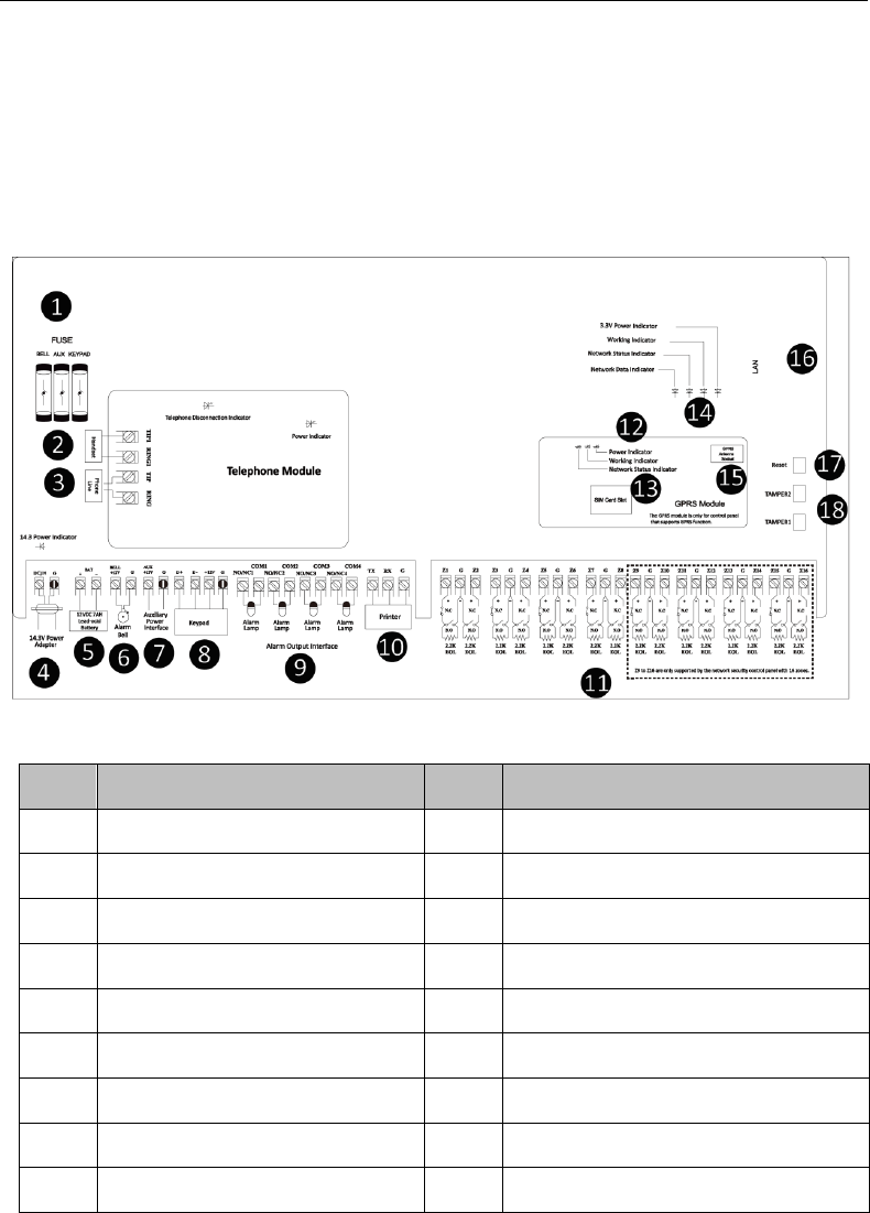
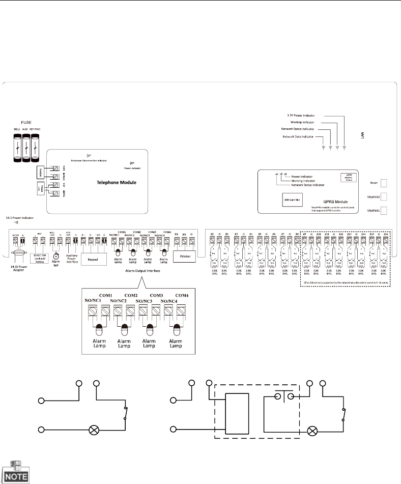
2.1 Main Board Overview
Main Board Overview
No.
Description
No.
Description
1
Fuse
10
Printer Wiring Interface
2
Incoming Telco Line Interface
11
Alarm Input Interface
3
Handset Interface
12
Wireless Network Module Indicator
4
Power Adapter
13
SIM Card Slot
5
Lead-acid Battery
14
Wired Network Module Indicators*
6
Alarm Bell
15
GPRS Antenna Socket
7
Auxiliary Power Interface
16
LAN Interface
8
Keypad Connection Interface
17
Reset Button
9
Alarm Output Interface
18
TAMPER Switches*
Control Panel User Manual
15
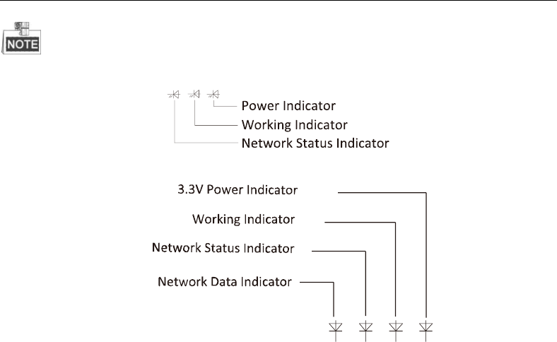
Wireless Network Module Indicator
The distribution of wireless network module indicators is shown below.
Wired Network Module Indicator
The distribution of wired network module indicator is shown below.
TAMPER Switches
TAMPER2 indicates the movement alarm switch.
TAMPER1 indicates the tampering alarm switch.
2.2 Device Wiring
2.2.1 Detector Wiring
The alarm input interfaces of the control panel are show as follows.
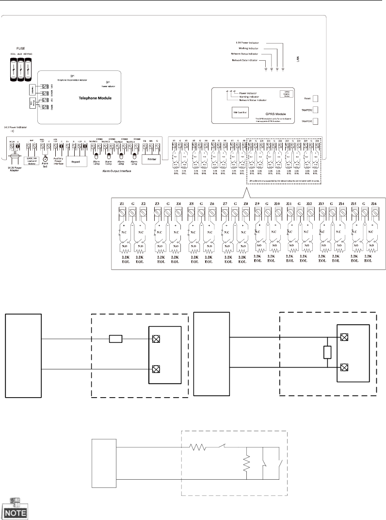
Control Panel User Manual
16
The wiring of sensor is shown as follows.
2.2KΩ
NC
C
Z
G
Peripheral Security DetectorAlarm Host
NC Detector
2.2KΩ
NO
C
Z
G
Alarm Host
NO Detector
Peripheral Security Detector
The Tamper-proof wiring is shown below.
2.2KΩ
2.2KΩ
ZONE
GND
DETECTOR
NC
NO
TAMPER
The resistance of 2.2KΩ,3.3KΩ, 5.6KΩ, and 8.2KΩ are all supported for the control panel.
Only 2.2KΩ resistance can be used for tamper-proof. For being compatible with the EOL,
you should configure the EOL resistance value of the corresponded zone.
Control Panel User Manual
17
2.2.2 Alarm Output Wiring
The alarm output interfaces of the control panel are show as follows.
The wiring of alarm output is shown as follows:
External Device
NO/NC
COM
DC12V
Breaker
External DC Load
External Device
NO/NC
COM
DC12V
Breaker
External AC Load
Relay (30V/1A)
The DC current supplied by the control panel is used for external devices. The load current
cannot be over 1A.
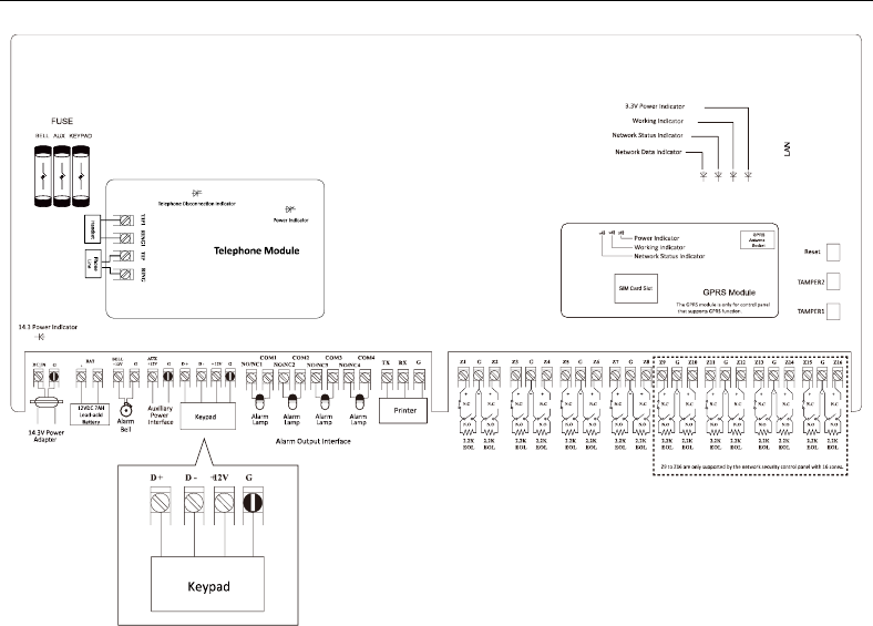
2.2.3 Keypad Wiring
The keypad wiring is shown as follows.
Control Panel User Manual
18
Control Panel User Manual
19
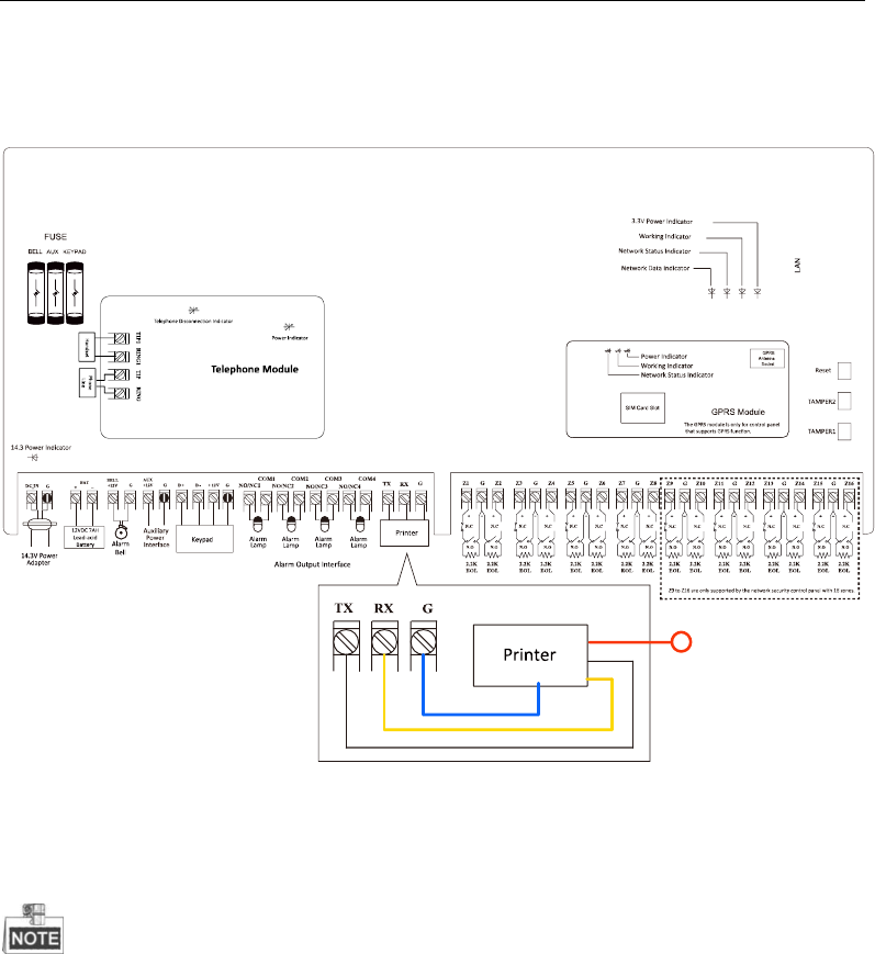
2.2.4 Printer Wiring
The printer wiring is shown below.
2.3 System Start-up
For configuring the security control panel, you should restore the system of the control
panel after start-up.
2.3.1 Control Panel Start-up
The keypad registration will be completed in 10 seconds after the control panel being
power on. The system then will complete the start-up and enter the properly status of
working.

Control Panel User Manual
20
2.3.2 Alarm Keypad Start-up
The LED keypad will make continuously prompt tones if the keypad does not receive the
registration respond from the control panel in 20 seconds after it being power on. While
the registration is succeeded, the working status indicator will turn green.
LED Alarm Keypad
LED Alarm Keypad Armed Indicator
Working Status
Indicator Status
Partition Arming
Red (Continuously Light)
Partition Disarming
Green (Continuously Light)
In Programming
Green (Flickering)
Main Operator Password Editing
Green (Flickering)
Remote Control Connecting
Green (Flickering)
Pacing Mode
Red (Continuously Light)
LED Alarm Keypad Run Indicator
Working Status
Indicator Status
Normal
Green (Continuously Light)
In Project
Red (Continuously Light)
System Fault
Orange (Flickering)
Main Operator Password Editing
Green (Flickering)
In Programming
Green (Flickering)
Unregistered Keypad
Red (Flickering)
LED Alarm Keypad Channel Indicator
Working Status
Indicator Status
Normal
Off
Alarm
Red (Flickering)
Exception
Red (Continuously Light)
Bypass
Green (Continuously Light)
Control Panel User Manual
21
LED Alarm Keypad Channel Indicator Status in Project Mode
No.
Description
No.
Description
1
Off-hook
5
Send CID Report
2
Dialing
6
Receive Confirmation Sound
3
Alarm Connecter Disconnection
7
Control Panel On-hook
4
Receive Hands-shake Sound
8
Alarm Connecter On-hook
LED Alarm Keypad Channel Indicator Status in Status Mode
No.
Description
No.
Description
1
AC Power Outages
5
RS485 Device Disconnection
2
Low Battery for Accumulator
6
Wired Network Exception
3
Control Panel Tampering Alarm
Enabled
7
Wireless Network Exception
4
Telephone Line Disconnection
8
Reserved
LCD Alarm Keypad
The system status display demonstration indicates the keypad display interface of system
status without any key pressing.
Powering on Display Demonstration
The display demonstration after powering on is shown below.
HIKVISION
System Status (normal) Display Demonstration
The display demonstration of system status (working properly) is shown below.
Global Keypad
SYS1D SYS2R SYS3A SYS4R
SYS5R SYS6R SYS7R SYS8R
The system status description is shown below.
System Status
Description
SYS1D
Partition1 Disarmed
SYS2R
Partition2 Ready
SYS3A
Partition3 Armed
SYS4R
Partition4 Ready
Control Panel User Manual
22
System Status
Description
SYS5R
Partition5 Ready
SYS6R
Partition6 Ready
SYS7R
Partition7 Ready
SYS8R
Partition8 Ready
Partition Keypad
HIKVISION
System Fault
Keypad Standby Status Display Demonstration
The standby status display demonstration is shown below.
HIKVISION
SYS1D SYS2R SYS3A SYS4R
SYS5R SYS6R SYS7R SYS8R
V1.2.1 build 131211
2014.04.18 19:24:26
The LCD keypad displays the version of the control panel and the time of operation.
Global Keypad Programming Status Display Demonstration
The programing status includes normal status and abnormal status. The demonstration is
shown below.
Normal Status
Programming...
Abnormal Status
Zone/Module Exception
Programming...
System Status (abnormal) Display Demonstration
Global Keypad
SYS1D SYS2R SYS3A SYS4R
SYS5R SYS6R SYS7R SYS8R
Partition Keypad

Control Panel User Manual
23
The system exception display of the partition keypad includes interfaces of alarm, fault and
bypass.
Zone Alarm
Zone Alarm
001 002 003 004 005 006
Zone Offline
Zone Offline
001 002 003 004 005 006
Zone Fault
Zone Fault
001 002 003 004 005 006
Zone Bypass
Zone Bypass
001 002 003 004 005 006
System Pacing Display Demonstration
The system pacing display demonstration is shown below.
Work Test
001 002 003 004 005 006
System Fault Display Demonstration
The system fault display demonstration is shown below.
AC Power Off;
Low Battery Voltage;
Display Demonstration in Project Mode
The demonstration is shown below.
Network1: Connecting…
Network1: Connected
Network1: Sending Report…
Network1: Sending report
succeeded.
Control Panel User Manual
24
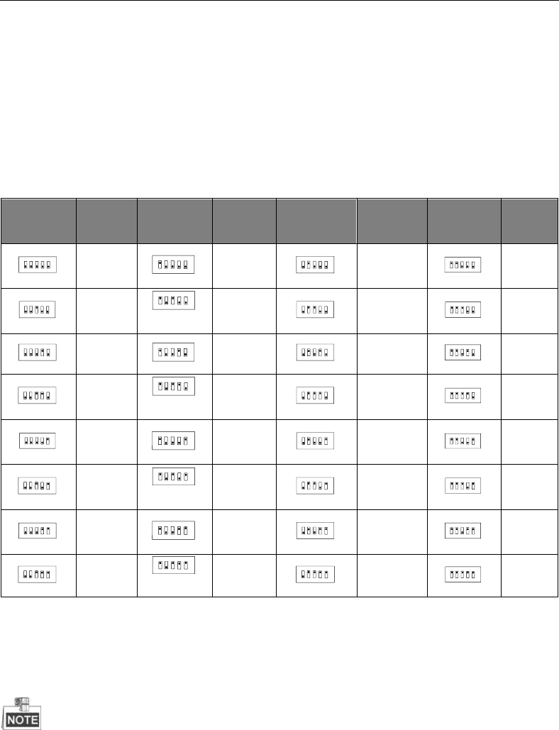
2.3.3 Keypad Address
An address is required for each alarm keypad in the system. These addresses cannot be
repeated. Once exchanging the alarm keypad, the address of the new keypad must be the
same as the replaced one. You should configure the address via DIP switch of the keypad
before powering on the system. The address should be in the range of 0~31.
DIP
Add.
DIP
Add.
DIP
Add.
DIP
Add.
21 3 4 5
ON DIP
0
21 3 4 5
ON DIP
1
21 3 4 5
ON DIP
2
21 3 4 5
ON DIP
3
21 3 4 5
DIP
ON
4
21 3 4 5
DIP
ON
5
21 3 4 5
DIP
ON
6
21 3 4 5
DIP
ON
7
21 3 4 5
ON DIP
8
21 3 4 5
ON DIP
9
21 3 4 5
ON DIP
10
21 3 4 5
ON DIP
11
21 3 4 5
DIP
ON
12
21 3 4 5
DIP
ON
13
21 3 4 5
DIP
ON
14
21 3 4 5
DIP
ON
15
21 3 4 5
ON DIP
16
21 3 4 5
ON DIP
17
21 3 4 5
ON DIP
18
21 3 4 5
ON DIP
19
21 3 4 5
DIP
ON
20
21 3 4 5
DIP
ON
21
21 3 4 5
DIP
ON
22
21 3 4 5
DIP
ON
23
21 3 4 5
ON DIP
24
21 3 4 5
ON DIP
25
21 3 4 5
ON DIP
26
21 3 4 5
ON DIP
27
21 3 4 5
DIP
ON
28
21 3 4 5
DIP
ON
29
21 3 4 5
DIP
ON
30
21 3 4 5
DIP
ON
31
2.3.4 Factory Settings
If powering on the system before zone connection, a 2.2k Ohm resistance is required for
bridge connection between each zone.
Password and Report
Installer Password: 012345
Main User Password: 1234
Power Recovery Default Installer Password: No

Control Panel User Manual
25
Arming/Disarming Report: Yes
Control Panel Duress Report: N/A
CID Report:
Account#1#2: No
Dialing Type: DTMF
Key fobs Programming: No
For Detailed CID code, Please refer to CID Report.
Zone:
Zone 1 to 8/16: Real-time zone
Urgent Soft Zone: Buzzing prompt sound
Test:
Testing Report Interval:N/A
Timing:
Entering Duration: 10 sec
Exiting Duration: 30 sec
Belling Duration: 5 min
Network Parameters:
IP Address: 192.0.0.64
Port No.: 8000
2.3.5 Activating the Control Panel
Purpose:
You are required to activate the control panel first before you can use the control panel.
Activation via SADP, and Activation via client software are supported.
Activation via SADP Software
SADP software is used for detecting the online device, activating the device, and resetting
the password.
Get the SADP software from the supplied disk or the official website, and install the SADP
according to the prompts. Follow the steps to activate the control panel.
Steps:
1. Run the SADP software to search the online devices.
2. Check the device status from the device list, and select an inactive device.
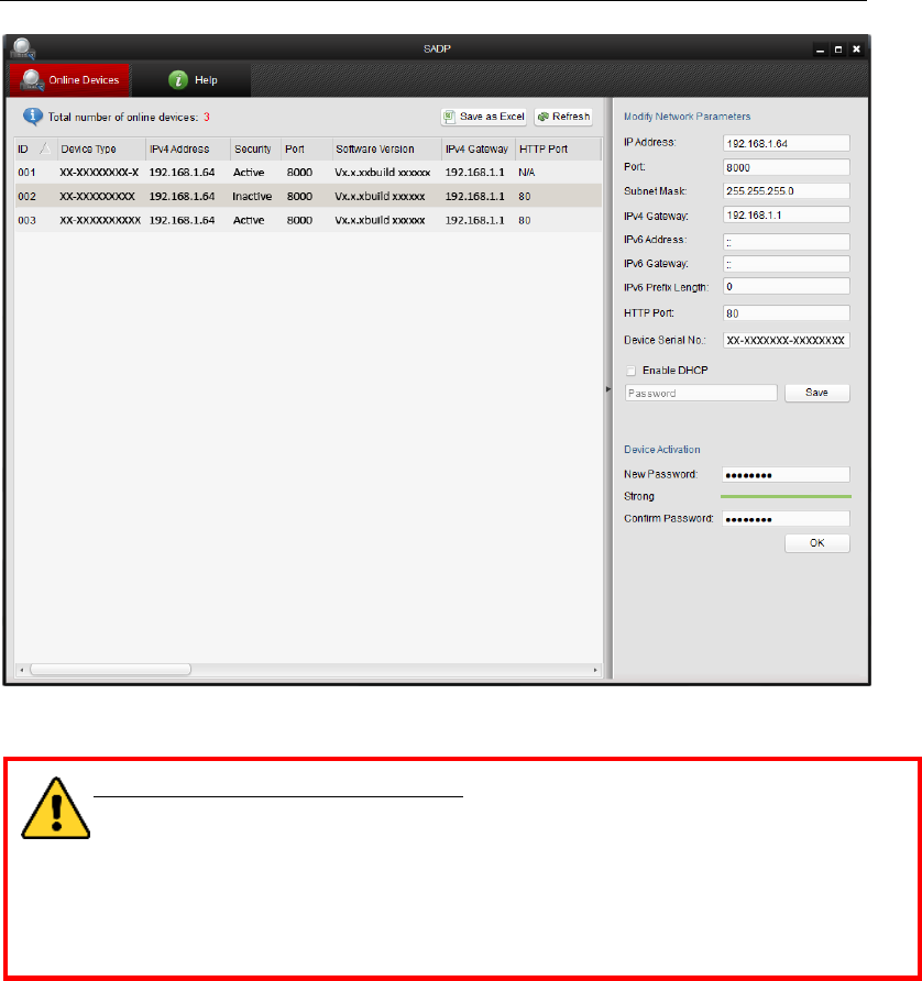
Control Panel User Manual
26
3. Create a password and input the password in the password field, and confirm the
password.
STRONG PASSWORD RECOMMENDED– We highly recommend you create a
strong password of your own choosing (using a minimum of 8 characters,
including upper case letters, lower case letters, numbers, and special
characters) in order to increase the security of your product. And we
recommend you reset your password regularly, especially in the high security
system, resetting the password monthly or weekly can better protect your
product.
4. Click OK to save the password.
You can check whether the activation is completed on the popup window. If activation
failed, please make sure that the password meets the requirement and then try again.
5. Change the device IP address to the same subnet with your computer by either
modifying the IP address manually or checking the checkbox of Enable DHCP.
Control Panel User Manual
27
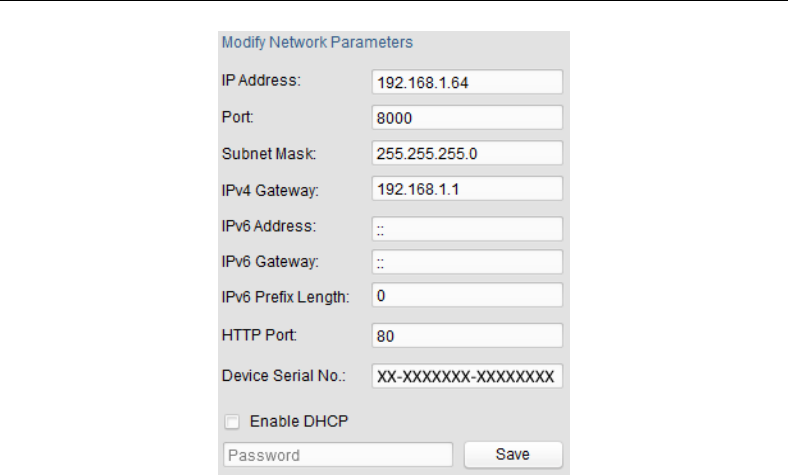
6. Input the password and click the Save button to activate your IP address modification.
Activation via Client Software
The client software is versatile video management software for multiple kinds of devices.
Get the client software from the supplied disk or the official website, and install the
software according to the prompts. Follow the steps to activate the control panel.
Steps:
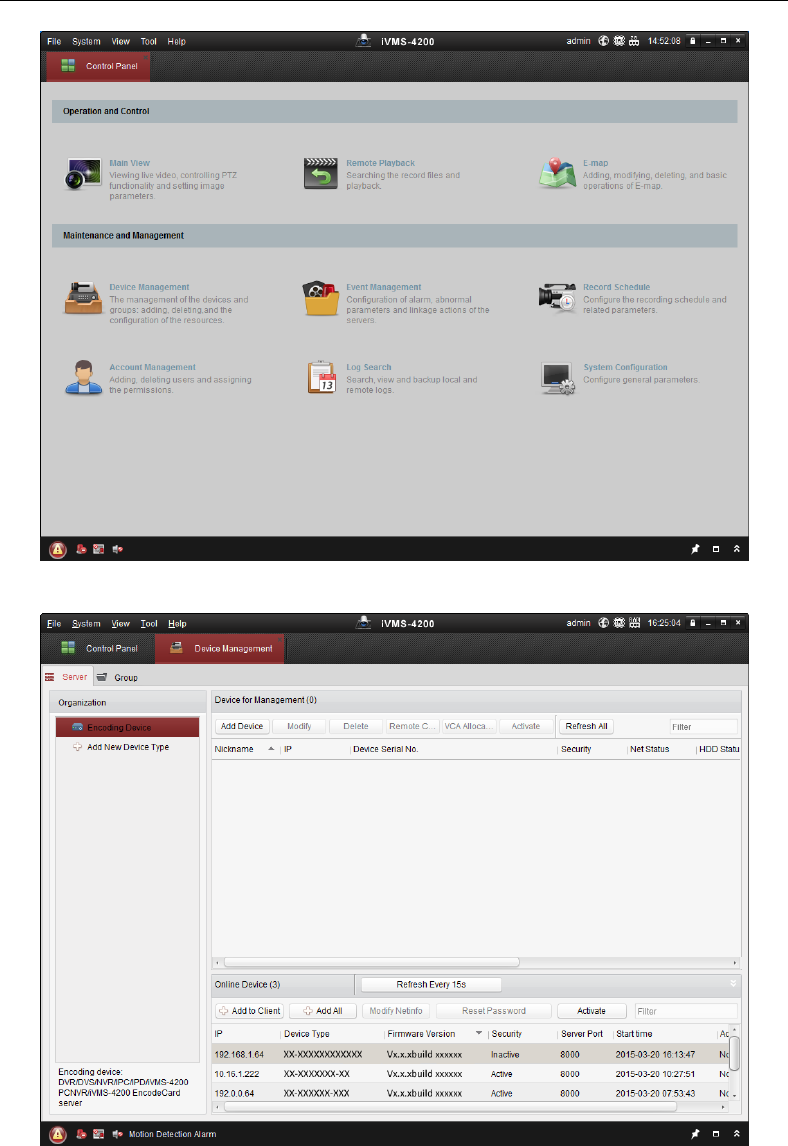
1. Run the client software and the control panel of the software pops up, as shown in the
figure below.
Control Panel User Manual
28
2. Click the Device Management icon to enter the Device Management interface, as
shown in the figure below.
Check the device status from the device list, and select an inactive device.
Control Panel User Manual
29
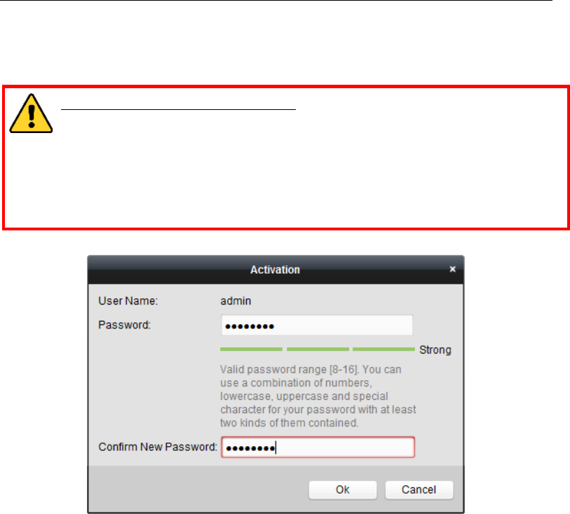
3. Click the Activate button to pop up the Activation interface.
4. Create a password and input the password in the password field, and confirm the
password.
STRONG PASSWORD RECOMMENDED– We highly recommend you create a
strong password of your own choosing (using a minimum of 8 characters,
including upper case letters, lower case letters, numbers, and special
characters) in order to increase the security of your product. And we
recommend you reset your password regularly, especially in the high security
system, resetting the password monthly or weekly can better protect your
product.
5. Click OK button to start activation.
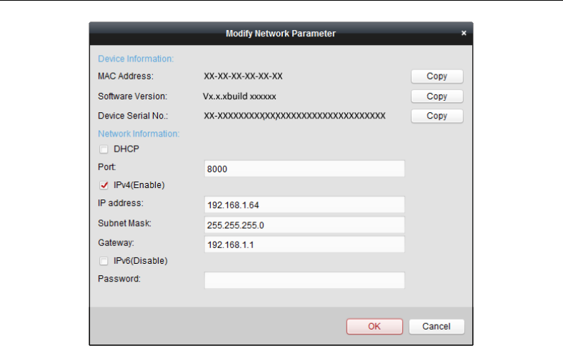
6. Click the Modify Netinfo button to pop up the Network Parameter Modification
interface, as shown in the figure below.
Control Panel User Manual
30
7. Change the device IP address to the same subnet with your computer by either
modifying the IP address manually or checking the checkbox of Enable DHCP.
Input the password to activate your IP address modification.
Control Panel User Manual
31
Chapter 3 Keypad Operation (Local
Operation)
3.1 Alarm Keypad Configuration
You should access the programming mode (only installer can access the programming mode)
before keypad configuration. The command is shown below:
012345 *0#
1 2
{1} Installer password: 012345
{2} Command Key: *0 #
The command for exiting programming mode is *#.
3.1.1 Installer Password Settings
The password of installer is used for accessing programming and initializing mode. The
command is shown below.
000 012345 #
1 2 3
{1} Installer Password Programming Address: 000.
{2} Installer Password: The default password is 012345. The length of the configured
password should be 1~ 6 characte.
{3} End the command.
3.1.2 Operator Configuration
The programming command of operator configuration is shown below.

Control Panel User Manual
32
001 *2 1234 #
1 2 3 4
{1} Operator Programming Address: 001~016.
{2} User Permission: 12 permissions. For details, please refer to the following table.
{3} Specified the username and password, the length of user name should be in the
range of 2 to 5 characters.
{4} End the command.
The username and password cannot be empty. If the password is configured as 0, the user
will be deleted. The password of 00, 000, 0000, or 00000 all signify of deleting the user.
The default password of the main operator is 1234 with the permission of 2. The default
permission of other operators is 6.
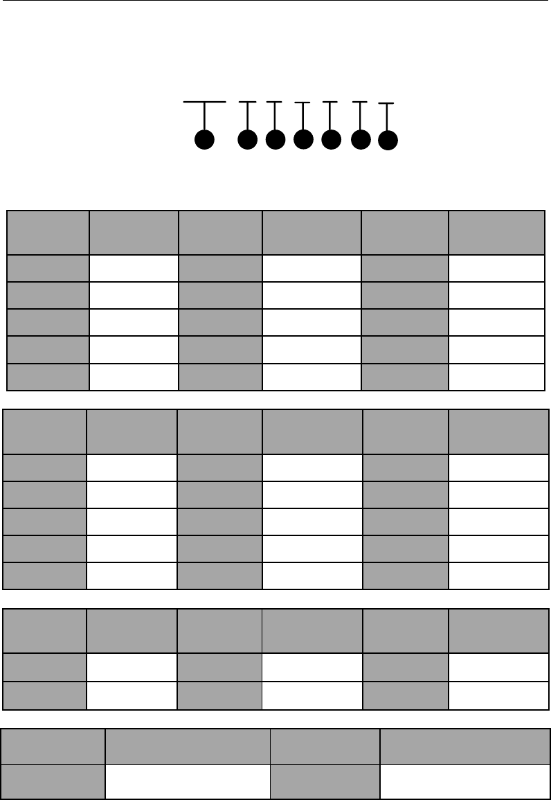
3.1.3 Zone Parameters Configuration
The parameters of zone include zone response time, zone arming type, linked local alarm
output, linked siren output. The detailed command is shown below.
No.
Permission
No.
Permission
1
Arming
No Arming Report
Unavailable Bypass
2
Arming/Disarming
No Disarming Report
Unavailable Bypass
3
Arming/Disarming
No Arming/Disarming Report,
Unavailable Bypass
4
Arming
Arming Report
Unavailable Bypass
5
Disarming
Disarming Report
Unavailable Bypass
6
Arming/ Disarming
Arming/Disarming Report
Unavailable Bypass
7
Arming
No Disarming Report
8
Disarming
No Arming/Disarming Report
9
Arming/Disarming
No Arming/Disarming Report
Bypass
*0
Arming
Arming Report
Bypass
*1
Disarming
Disarming Report
Bypass
*2
Arming/Disarming
Arming/Disarming Report
Bypass
Control Panel User Manual
33
201 2 5 0 1 0 1 0 0 1 1 1 #
12 4 63 5 87 910 11 12 13
{1} Zone Parameters Programming Address: 201~208/216
For 8-zone network security control panel , the zone parameters programming
address is 201~208.
For 16-zone network security control panel, the zone parameters
programming address is 201~216.
{2} Zone Response Time. The 4 kinds of zone response time is shown as follows.
Command
Command Description
Command
Command Description
0
10 ms
1
250 ms
2
500 ms
3
750 ms
{3} Zone Arming Type
Command
Command Description
Command
Command Description
0
None
1
24-hour voiced zone
2
Delay Zone
3
Internal Delay Zone
4
Key Arming/Disarming Zone
5
Real-time Zone
6
Fire Zone
7
24-hour non-voiced Zone
8
Stay Arming
{4} Linked Relay (Reserved)
{5} Liked Alarm Output.
Command
Command Description
Command
Command Description
0
Non-linked Alarm
Output
1
Linked Alarm Output
{6} Bypass Group
Command
Command Description
Command
Command Description
0
Unsuport
1
Support
{7} Alarm Recovery Report.
Command
Command Description
Command
Command Description
0
No Alarm Recovery
Report
1
Alarm Recovery Report

Control Panel User Manual
34
{8} Zone Loop Type
Command
Command Description
0
Zone Loop without Tampering Prevention
Switch
1
NC Type of Loop with Tampering Prevention
Zone Loop
2
NO Type of Loop with Tampering Prevention
Zone Loop
The fire alarm zone do not support the configuration of zone loop type, and can
only be set as 0,or an error value will be returned.
{9} Tampering Prevention Linked Relay
Command
Command Description
Command
Command Description
0
Non-linked Local Alarm
Output
1
Linking Local 1 Alarm
Output
2
Linking Local 2 Alarm
Output
3
Linking Local 1/2Alarm
Output
4
Linking Local 3 Alarm
Output
5
Linking Local 1/3 Alarm
Output
6
Linking Local 2/3 Alarm
Output
7
Linking Local 1/2/3 Alarm
Output
8
Linking Local 4 Alarm
Output
9
Linking Local 1/4 Alarm
Output
*0
Linking Local 2/4 Alarm
Output
*1
Linking Local 1/2/4Alarm
Output
*2
Linking Local 3/4 Alarm
Output
*3
Linking Local 1/3/4 Alarm
Output
*4
Linking Local 2/3/4 Alarm
Output
*5
Linking Local 1/2/3/4 Alarm
Output
{10} Tampering Prevention Linked Siren Output
Command
Command Description
Command
Command Description
0
No Linked Siren Output
1
With Linked Siren
Output
{11} Tampering Alarm Recovery Report
Control Panel User Manual
35
Command
Command Description
Command
Command Description
0
No Tampering
Prevention Recovery
Report
1
With Tampering
Prevention Recovery
Report
{12} End of line resistors
Command
Resistance Value
Command
Resistance Value
0
2.2KΩ
1
3.3KΩ
2
4.7KΩ
3
5.6KΩ
4
8.2KΩ
The resistance of 2.2KΩ or 3.3KΩ supports tamper-proof and
non-tamper-proof wiring.
The resistance of 4.7KΩ only supports tamper-proof wiring.
The resistance of 5.6KΩor 8.2KΩ only supports non-tamper-proof wiring.
{13} End the command.
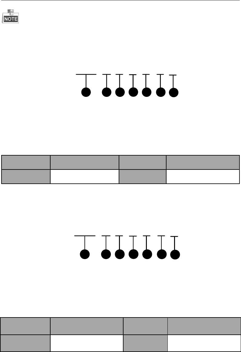
3.1.4 Telco Line Communication Control
The communication control command is used for setting the phone connection mode of
alarm center 1 and 2. The detailed command is shown below.
457 0 0 3 3 #
1 2 4 63 5
{1} The Telco line communication control programming address: 457
{2} Dialing Mode of Telephone Center1
{3} Dialing Mode of Telephone Center2
Command
Command Description
Command
Command Description
0
DTMF- double tone&
multi-frequency (5/sec)
1
DTMF- double tone&
multi-frequency
(10/sec)
{4} Dialing Times of Telephone Center1
{5} Dialing Times of Telephone Center2
Control Panel User Manual
36
Command
Command
Description
Command
Command Description
1
1
9
9 Times
2
2 Times
*0
10 Times
3
3 Times
*1
11 Times
4
4 Times
*2
12 Times
5
5 Times
*3
13 Times
6
6 Times
*4
14 Times
7
7 Times
*5
15 Times
9
8 Times
{6} End the command.
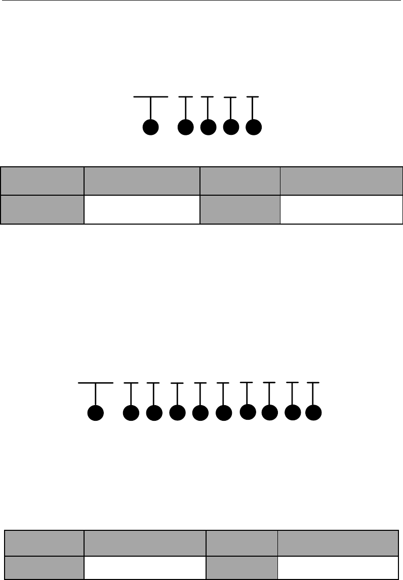
3.1.5 Dialing Account Configuration
The control panel supports phone dialing to upload alarm information. The dialing account
command is shown below.
458 0 0 0 0 #
1 2 4 63 5
{1} Dialing Account Programming Address: 458~459
Command
Command Description
Command
Command Description
458
Corresponding Alarm
Center 1 Dialing Account
459
Corresponding Alarm Center
2 Dialing Account
{2}~{5} Account No.. The value range of the account No. is 0~F.
It is recommended that the dilaing account should be the same as the allocated account of
the alarm connecter.
{6} End the command.
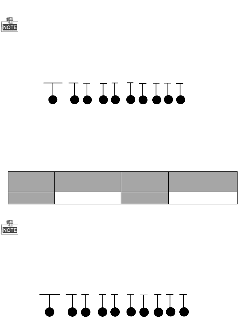
3.1.6 Alarm Receiver Phone Number Settings
The control panel supports two dialing accounts. The maximum length of dialing number of
Control Panel User Manual
37
each account is 31 digits. The command is shown as follows.
460 E0 ∙∙∙∙∙∙0 #
1 2 3
{1} Programming Address of Phone Number of Alarm Connecter: 460~463
Address
Command Description
Address
Command
Description
460
Alarm Center1 Phone
Number Programming
Address
462
Alarm Center2 Phone
Number
Programming Address
461
463
A telephone number is separated into two segments. The 460 and 461 group represents the
dialing number which is connected with alarm center1. The 462 and 463 group represents
the dialing number which is connected with alarm center2.
{2} The dialing number is 16 digits.
All the telephone number should be end with *4.
The length of the each center number is 31 digits, and the entering format
should be {No.} + {Dwell Time} + {ext.No.}
The default center number is E0000000000000000000000000000000.
{3} End the command.
Example 1:
If the tele-phone number is 0571-88075998, you can enter 460057188075998*4# with the
keypad for completing the configuration.
Example 2:
If the telephone number is 17951-88075998, there are two steps to set the phone number
via the keypad.
Steps:
1. Enter 46017951FFF88075998# with the keypad.
2. Enter 461*4# to complete the settings.
3.1.7 Zone Associated Relay Configuration
The detailed programming command is shown below.
467 000 0 00 #
143 5
2
{1} Relay Configuration Programming Address: 467
Control Panel User Manual
38
{2} Zone No.
{3} Add/Delete Relay
Command
Command Description
Command
Command Description
0
Delete
1
Add
{4} Relay No.
{5} End the command.
After successfully operating once, you can continuously do configuration with the
command of {Project} + {Relay No.} + {#}.
No more than 9 relays can be linked.
3.1.8 Relay Event Linkage Configuration
For relay event linkage configuration, please refer to the command below.
468 000 0 00 00 #
1 4
2356
{1} The programming address of enabling relay event linkage is 468~469.
Command
Function Description
Command
Function Description
468
Enable Relay Event
Linkage
469
Disable Relay Event
Linkage
{2} Relay No.
{3} Add/ Delete Relay
Command
Function Description
Command
Function Description
0
Delete Relay
1
Add Relay
{4} Selecting Device/ System
Command
Function Description
Command
Function Description
00
Device
01
System
{5} Event No.
The device event command is shown below.
Control Panel User Manual
39
Command
Command
Description
Command
Command
Description
Command
Command
Description
00
None
01
AC Power
Down
02
Low Battery
03
Telephone Line
Disconnection
04
Wired
Network
Exception
05
No Network
Exception
The system event command is shown below.
Command
Command
Description
Command
Command
Description
Command
Command
Description
01
Entering
Delay
02
Exiting Delay
03
Arming
04
Disarming
05
Alarm
06
Alarm Clearing
07
Alarm
Recovery
{6} End the command.
After successfully operating once, you can continuously do configuration with the command
of {Project} + { Relay No.} + {System Command.} + {Event Command} + {#}.
3.1.9 Relay Time Settings
For Relay output time settings, please refer to the command below.
470 000 00 00 #
1 4
235
{1} Relay Time Programming Address: 470
{2} Relay No.
{3} Duration: In minute
{4} Duration: In second
{5} End the command.
The maximum duration of triggering is 99 minutes and 59 seconds. The default duration is
30 seconds.
After operating once, you can continuously configure with the command of {Project} +
Control Panel User Manual
40
{Relay No.} + {Duration} + {#}
3.1.10 Siren Configuration
For siren configuration, please refer to the command below.
471 1 #
12 3
{1} Siren Configuration Programming Address: 471
{2} Enable/Disable Siren Command
Command
Command Description
Command
Command Description
0
Disable
1
Enable
{3} End the Command.
3.1.11 Control Panel Time Settings
For control panel time settings, please refer to the command below.
472 0000 00 00 00 00 00 #
1 2 4 6
35 7 8
{1} Control Panel Time Settings Programming Address: 472
{2} Year
{3} Month
{4} Day
{5} Hour
{6} Minute
{7} Second
{8} End the Command.
3.1.12 Control Panel IP Configuration
For control panel IP configuration, please refer to the command below.
Control Panel User Manual
41
473 192 000 000 064 #
1 2 36
54
{1} Control Panel IP Configuration Programming Address: 473.
{2} Unit 1
{3} Unit 2
{4} Unit 3
{5} Unit 4.
{6} End the command.
The IP address programming includes 12 digits. The 1 to 12 place indicates the IP address of
the control panel. Each unit of the IP address includes 3 digits. You should enter 0 if the
entered address is less than 3 digits for each unit for complement. For example, you should
enter 192 002 028 066 for validating the IP address of 192.2.28.66.
3.1.13 Local Port Number Configuration
The programming command of local port number setting is shown below:
474 0 8 0 0 0 #
1 2 463 5 7
{1} The programming command address of local port number setting is: 474;
{2} Port: Ten Thousands’ Digit
{3} Port: Thousands’ Digit
{4} Port: Hundreds’ Digit
{5} Port: Tens’ Digit
{6} Port: Units’ Digit
{7} End the command.
Corresponding port number must be 5 digits. When the place is not sufficient, fill it up with
0.
For example: When the port number is 6000, the programming command is: 474 06000#.
3.1.14 Subnet Mask Configuration
The programming command of control panel subnet mask setting is shown below:
Control Panel User Manual
42
475 255 255 255 000 #
12 4 63 5
{1} The programming command address of control panel subnet mask setting is: 475;
{2} The First Unit;
{3} The Second Unit;
{4} The Third Unit;
{5} The Fourth Unit;
{6} End the command.
3.1.15 Gateway Configuration
The programming command of gateway settings is shown below:
476 000 000 000 000 #
12 4 63 5
{1} The programming command address of control panel gateway setting is: 476;
{2} The First Unit;
{3} The Second Unit;
{4} The Third Unit;
{5} The Fourth Unit;
{6} End the command.
3.1.16 GPRS Configuration
The programming command of GPRS settings is shown below:
477 0 0 #
14
23
{1} The programming command address of GPRS setting are: 477
{2} Name of APN;
Command
Description
Command
Description
1
CMNET
2
UNINET
{3} Time of detecting link;
Command
Time
Command
Time
0
10s
8
170s
1
30s
9
190s
2
50s
*0
210s
Control Panel User Manual
43
Command
Time
Command
Time
3
70s
*1
230s
4
90s
*2
250s
5
110s
*3
270s
6
130s
*4
290s
7
150s
*5
300s
{4} End the command.
3.1.17 SIM Card No. Configuration
The programming command of SIM Card No. settings is shown below:
478 0 0 0 0 0 0 0 0 0 0 0 #
12 4 63 5 87 910 11 12 13
{1} The programming command address of SIM card No. settings is 478.
{2}~{12} SIM card No.
{13} End the command.
3.1.18 Uploading Center IP Configuration
The programming command of uploading center IP setting is shown below:
485 000 000 000 000 #
1 2 4 63 5
{1} The programming command address of uploading center IP setting are:
485,488,491,494;
Command
Description
Command
Description
485
Programming Address of
Network Center 1 IP Settings
488
Programming Address of
Network Center 2 IP
Settings
491
Programming Address of
GPRS Center 1 IP Settings
494
Programming Address of
GPRS Center 2 IP Settings
{2} The First unit;
{3} The Second unit;
{4} The Third unit;
Control Panel User Manual
44
{5} The Fourth unit;
{6} End the command.
3.1.19 Center Port No. Configuration
The programming command of uploading center port setting is shown below:
486 00000 #
12 3
{1} The programming command addresses of uploading center port setting are: 486,
489, 492, 495;
Command
Description
Command
Description
486
Programming Address of
Network Center 1 Port
Settings
489
Programming Address of
Network Center 2 Port
Settings
492
Programming Address of
WIFI Center 1 Port Settings
495
Programming Address of
WIFI Center 2 Port Settings
{2} Port number;
{3} End the command.
3.1.20 Center Protocol and Account Configuration
The programming command of center protocol and account setting is shown below:
487 2 000000000 #
134
2
{1} The programming command addresses of center protocol and account settings
are: 487, 490, 493, 496;
Command
Description
Command
Description
487
Network Center 1 Protocol
and Programming Address
of Account Settings
490
Network Center 2 Protocol
and Programming Address
of Account Settings
493
GPRS Center 1 Protocol
and Programming Address
of Account Settings
496
GPRS Center 2 Protocol and
Programming Address of
Account Settings
Control Panel User Manual
45
{2} Protocol Type:
Command
Description
1
HIK
{3} Account;
{4} End the command.
3.1.21 Printer Settings
Printer Parameters Settings
The programming commands of printer parameters setting are as below:
499 0 0 0 #
12 3 45
{1} The programming command address of printer parameter setting is:499;
{2} Enable/disable the printer;
Command
Description
Command
Description
0
Disable the Printer
1
Enable the Printer
{3} Enable/disable the off-line detection of printer;
Command
Description
Command
Description
0
Disable the Off-line
Detection of Printer
1
Enable the Off-line
Detection of Printer
{4} Whether to print the reporting time or not, known as the time of control panel
when event/alarm occurs;
Command
Description
Command
Description
0
Not print the reporting
time
1
Print the reporting time
{5} End of the command.
Alarm Message Settings
The programming commands of print setting of alarm message are as below:
500 0 0 0 #
12 3 45
{1} The programming command address of alarm message printing is: 500.
Control Panel User Manual
46
{2} Enable/disable the sensor alarm;
Command
Description
Command
Description
0
Disable Sensor Alarm
1
Enable Sensor Alarm
{3} Enable/disable emergency alarm;
Command
Description
Command
Description
0
Disable Emergency
Alarm
1
Enable Emergency
Alarm
{4} Enable/disable duress alarm;
Command
Description
Command
Description
0
Disable Control Panel
Duress Alarm
1
Enable Duress Alarm
{5} End the command.
Device Information Settings
The programming commands of print setting of device information are as below:
501 0 0 0 0 0 0 0 0 #
1 2 463 579
810
{1} The programming command address of device information printing is: 501.
{2} AC Power Off;
{3} The storage battery is under voltage;
{4} The ADSL is off-line;
{5} Test Report;
{6} Tamper-proof of the Control Panel;
{7} The 485 device is off-line;
{8} Network error;
{9} Wireless connection exception.
It indicates disabled status when 2) ~9) are set to be 0, and indicates enabled status when 2)
~9) are set to be 1.
Command
Description
Command
Description
0
Disabled
1
Enabled
{10} End of the command.
Operation Programming Information Settings
The programming commands of print setting of operation programming information
Control Panel User Manual
47
are as below:
502 0 0 0 0 0 0 0 #
1 2 4 63 5 7 98
{1} The programming command address of print setting of operation programming
information is: 502;
{2} Arming;
{3} Disarming;
{4} Canceling the alarm;
{5} Bypass;
{6} Enter the programming;
{7} Exit the programming;
{8} Control Panel Restoring;
It indicates disabled status when 2) ~8) are set to be 0, and indicates enabled status when 2)
~8) are set to be 1.
Command
Description
Command
Description
0
Disabled
1
Enabled
{9} End the command.
Restoring Information of Alarm and Bypass Settings
The programming commands of print setting of restoring information of alarm and bypass
are as below:
503 0 0 #
12 3 4
{1} The programming command address of print setting of restoring information of
alarm and bypass is: 503;
{2} Sensor Alarm Recovering;
Command
Description
Command
Description
0
Disabled
1
Enabled
{3} Bypass Recovering;
Command
Description
Command
Description
0
Disabled
1
Enabled
{4} End the command.
Control Panel User Manual
48
Device Recovering Information Settings
The programming commands of print setting of device recovering information are as below:
504 0 0 0 0 0 0 0 #
1 2 46
35789
{1} The programming command address of print setting of device recovering
information is: 504;
{2} AC power on;
{3} The storage battery is not under voltage;
{4} The ADSL is on-line;
{5} The tamper-proof of the control panel is recovered;
{6} The 485 device is on-line;
{7} The network error is recovered;
{8} The wireless connection exception is recovered.
It indicates disabled status when 2) ~8) are set to be 0, and indicates enabled status when 2)
~8) are set to be 1.
Command
Description
Command
Description
0
Disabled
1
Enabled
{9} End of command.
3.1.22 Siren Linked Event Configuration
509 0 00 00 00 #
12 3 4 5 6
{1} The programming command address of siren linked event configuration is
509(default: null)
{2} Add/Delete Event Configuration
Command
Description
Command
Description
0
Delete Event
1
Add Event
{3} Event Type
Command
Description
Command
Description
00
Global Event
01
Partition Event
{4} Detailed Event Type
The global event types are shown below.
Control Panel User Manual
49
Command
Description
Command
Description
Command
Description
00
Null
01
Control
Panel
Tampering
Alarm
02
Global
Keypad
Emergency
Alarm
03
Ac
Disconnected
04
Low Battery
Voltage
05
Telco Line
Disconnected
06
Wired
Network
Exception
07
Wireless
Network
Exception
08
Keypad /485
Device
Disconnected
The partition event types are shown below.
Command
Description
Command
Description
00
Null
01
Emergency Alarm
02
Arming
03
Disarming
{5} Partition No. (It is not necessary to enter the partition No. when configuring
global event)
Command
Description
Command
Description
Command
Description
00
Global
Partition
01
No.1
Partition
02
No.2
Partition
03
No.3
Partition
04
No.4
Partition
05
No.5
Partition
06
No.6
Partition
07
No.7
Partition
08
No.8
Partition
{6} End the command.
3.1.23 Emergency Alarm Linkage Configuration
The programming command of emergency alarm linkage settings is shown below:
510 00 0 #
1234
{1} The programming command address of emergency alarm linkage setting is: 510;
{2} Partition Number, 00 indicate the global keypad, 01~08 indicate partitions
Control Panel User Manual
50
No.1~No.8;
{3} Whether to link the siren or not;
Command
Description
Command
Description
0
Not link the Siren
1
Link the Siren
{4} End the command.
3.1.24 Control Panel Tampering Alarm Configuration
The programming command of control panel tampering alarm settings is shown below:
511 0 #
12 3
{1} The programming command address of control panel tampering alarm is: 511;
{2} whether to link the siren or not;
Command
Description
Command
Description
0
Not link the Siren
1
Link the Siren
{3} End the command.
3.1.25 Testing Report Configuration
The testing report is used to validate the communication of control panel and alarm center.
The detailed operation is show as follows.
513 0 1 5 #
1 2 3 54
{1} The testing report programming address is 513.
{2} Enable/Disable the Testing Report
Command
Command Description
Command
Command Description
0
Disable
1
Enable
{3} Timer of the Testing Report.
Control Panel User Manual
51
Command
Command Description
Command
Command Description
0
1/4H
4
3H
1
1/2H
5
4H
2
1H
6
6H
3
2H
7
8H
Command
Command Description
Command
Command Description
8
10H
*2
18H
9
12H
*3
20H
*0
14H
*4
22H
*1
16H
*5
24H
{4} Testing Report Sending Interval
Command
Command
Description
Command
Command
Description
Command
Command
Description
1
1H
4
12H
7
3D
2
2H
5
24H
8
5D
3
4H
6
2D
9
7D
{5} End the command.
3.1.26 Partition Configuration
Partition Start-up Configuration
The programming command of the partition start-up configuration is shown below.
531 1 1 #
142 3
{1} The programming of partition start-up configuration is: 531~538.
{2} The configuration item of 1 indicates the start-up configuration of the partition.
{3} Enable/Disable the Partition.
Command
Command Description
Command
Command Description
0
Disable
1
Enable
Control Panel User Manual
52
{4} End the command.
Only the No.1 partition is enabled as the default settings.
Partition Keypad User Configuration
The programming command of keypad user configuration of the partition is shown as
follows.
531 2 0 000 #
14
235
{1} The programming command address of keypad user configuration is 531~538.
{2} The configuration item of 2 indicates the keypad user configuration.
{3} Add/Delete the user.
Command
Command Description
Command
Command Description
0
Delete
1
Add
{4} The user No.
{5} End the command
Added Separately: for instance, to add an user with the No. of 160 to the No.8
partition, the command should be 538 2 1 160 #
Added/Deleted Continually: only continuous adding or deleting operation is
supported. After adding/deleting a user separately, enter the command
[Project]+[User No.]+[#] to continually add/delete users. For instance, to add users
with the No. of 2,3,and 5, the command should be 538 2 1 002 # Project # 003 #
Project # 005 #.
Added/Delete in Batch: the formate is 531 2 x xxx xxx #.
Added with user No. interval: for instance, to add users with the No. between
100~149 to the No.3 partition, the command should be 533.2.1.100.149 #.
Partition Zone Configuration
The programming command of zone configuration of the partition is shown below.
Control Panel User Manual
53
531 3 0 000 #
14
235
{1} The programming command addressof zone configuration is 531~538.
{2} The configuration item of 3 indicates zone configuration of the partition.
{3} Add/Delete Zone.
Command
Command Description
Command
Command Description
0
Delete
1
Add
{4} Zone No.
{5} End the command.
There are three mode to add/delete zone for the partition, adding/deleting separately,
Adding/ Deleting continually and adding/deleting in Batch, for details, refer to the
Partition Keypad User Configuration.
Partition Keypad Configuration
The programming command of keypad configuration of the partition is shown as follows.
531 4 0 00 #
14
235
{1} The programming command address of zone configuration is 531~538.
{2} The configuration item of 4 indicates keypad configuration.
Add/Delete
KeypadCommand
Command Description
Command
Command Description
0
Delete
1
Add
{3} Keypad No.
{4} End the command.
There are three mode to add/delete zone for the partition, adding/deleting separately,
Adding/ Deleting continually and adding/deleting in Batch, for details, refer to the
Partition Keypad User Configuration.
Control Panel User Manual
54
Partition Time and Control Panel Duress Report Configuration
To configure the system time and duress report, please see the command below.
531 5 1 3 2 0 #
1 2 463 5 7
{1} System Time and Duress Report Programming Address: 531
{2} Classification Option of System Time and Duress Report: 5
{3} Entering Delay
Command
Command
Description
Command
Command
Description
Command
Command
Description
1
10sec
6
60sec
*1
110sec
2
20sec
7
70sec
*2
120sec
3
30sec
8
80sec
*3
130sec
4
40sec
9
90sec
*4
140sec
5
50sec
*0
100sec
*5
150sec
{4} Exiting Delay
Command
Command
Description
Command
Command
Description
Command
Command
Description
1
10sec
6
60sec
*1
110sec
2
20sec
7
70sec
*2
120sec
3
30sec
8
80sec
*3
130sec
4
40sec
9
90sec
*4
140sec
5
50sec
*0
100sec
*5
150sec
{5} Siren Working Duration
Command
Command
Description
Command
Command
Description
Command
Command
Description
1
2min
2
5min
3
10min
4
15min
5
30min
{6} Enable/Disable Control Panel Duress Report
Command
Command Description
Command
Command Description
0
Disable
1
Enable
{7} End the command.
Control Panel User Manual
55
The 24-hour non-voiced zone does not support linked siren output.
Partition Report and Arming Prompt Sound Configuration
To configure the system report and arming prompt sound, please see the command below.
531 6 0 0 0 0 #
1 2 463 5 7
{1} system report and arming prompt sound programming address: 531
{2} Classification Option of Report and Arming Prompt Sound: 6
{3} Arming/disarming Report Ending Prompt Sound
{4} Manual Testing Report Sending Prompt Sound.
{5} Prompting sound of arming succeeded.
{6} Prompting sound of disarming succeeded
{3}~{6}
Command
Command Description
Command
Command Description
0
Disable
1
Enable
{7} End the command.
Partition Key User Permission Configuration
To configure the permission of key user, please see the command below.
531 7 1 1 1 1 #
1 2 463 5 7
{1} System key user permission programming address: 531.
{2} System key user classification option: 7
{3} Arming Permission
{4} Disarming Permission
{5} Arming Report Permission
{6} Disarming Report Permission
{3}~{6}
Command
Command Description
Command
Command Description
0
Disable
1
Enable
{7} End the command.
Control Panel User Manual
56
3.1.27 Public Partition Settings
The programming commands of public partition settings are as below:
563 0 0 0 #
1 2 4
3 5
{1} The public partition settings address is 563.
{2} Enable/Disable public partition.
Command
Command Description
Command
Command Description
0
Disable
1
Enable
{3} Associated Partition No.1.
{4} Associated Partition No.2.
{5} End the command.
3.1.28 Fault Detection Configuration
Control Panel System Fault Detection Configuration
To configure control panel system fault detection, please see the command below.
564 1 1 1 1 1 1 1 1 #
1 2 463 5 789 10
{1} Control panel system fault detection address: 564.
{2} Ac Power Down
{3} Low Battery
{4} Control Panel Tampering Alarm
{5} Phone Line Disconnection
{6} Main Keypad Disconnection
{7} Network Exception
{8} GPRS Network Exception
Command
Command Description
Command
Command Description
0
Disable
1
Enable
{9} Expension Bus Exception
Control Panel User Manual
57
{10} End the command.
If the fault detection is disabled, the control panel will not detect or report this sort of fault.
Keypad Fault Display Configuration
To configure the system fault display, please refer to the command below.
565 1 1 1 1 1 1 1 1 #
1 2 4 6
357 8 910
{1} Keypad fault display configuration programming address: 565
{2} Ac Power Down
{3} Low Battery
{4} Control Panel Tampering Alarm
{5} Phone Line Disconnection
{6} Main Keypad Disconnection
{7} Network Exception
{8} GPRS Exception
Command
Command
Description
Command
Command Description
0
Disable
1
Enable
{9} Expension Bus Exception
{10} End the command.
After successfully operating once, you can continuously do configuration with the command
of {Project} + {Partition No.} + {Configuration} + {#}.
Keypad Fault Prompt Sound Configuration
To configure the keypad fault prompt sound, please see the command below.
566 1 1 1 1 1 1 1 1 #
1 2 4 6
357 8 910
{1} Keypad fault prompt sound configuration programming address: 566.
{2} Ac Power Down
{3} Low Battery
{4} Control Panel Tampering Alarm
{5} Phone Line Disconnection
{6} Main keypad Disconnection
Control Panel User Manual
58
{7} Network Exception
{8} GPRS Exception
Command
Command
Description
Command
Command Description
0
Disable
1
Enable
{9} Expension Bus Exception
{10} End the command.
After successfully operating once, you can continuously do configuration with the command
of {Project} + {Partition No.} + {Configuration} + {#}.
Partition Fault Display Configuration
To configure the partition fault display, please see the command below.
567 01 01 1 1 1 1 1 1 1 1 #
12 4 63 5 7 8 9 10 11 12
{1} Partition fault display configuration programming address: 567.
{2} The Tens’ Digit of the Partition No.
{3} The Units’ Digit of the Partition No.
{4} Ac Power Down
{5} Low Battery
{6} Control Panel Tampering Alarm
{7} Phone Line Disconnection
{8} Main keypad Disconnection
{9} Neywork Exception
{10} GPRS Exception
Command
Command Description
Command
Command Description
0
Disable
1
Enable
{11} Expension Bus Exception
{12} End the command.
Partition Fault Prompt Sound Configuration
To configure the partition fault prompt sound, please see the command below.
568 01 01 1 1 1 1 1 1 1 1 #
12 4 63 5 7 8 9 10 11 12
Control Panel User Manual
59
{1} Partition fault display configuration programming address: 568.
{2} The Tens’ Digit of the Partition No.
{3} The Units’ Digit of the Partition No.
{4} Ac Power Down
{5} Low Battery
{6} Control Panel Tampering Alarm
{7} Phone Line Disconnection
{8} Main keypad Disconnection
{9} Network Exception
{10} GPRS Exception
Command
Command
Description
Command
Command Description
0
Disable
1
Enable
{11} Expension Bus Exception
{12} End the command.
3.1.29 Center Group Configuration
Center Group Enabling Configuration
To enable the center group, please see the command below.
611 0 #
12 3
{1} Center Group Enabling Programming Address: 611, 615, 619, 623, 627and 631.
Command
Command Description
Command
Command Description
611
Center Group 1
Enabling Programming
Address
615
Center Group 2
Enabling Programming
Address
619
Center Group 3
Enabling Programming
Address
623
Center Group 4
Enabling Programming
Address
627
Center Group 5
Enabling Programming
Address
631
Center Group 6
Enabling Programming
Address
{2} Enable/Disable the Center Group
Control Panel User Manual
60
Command
Command
Description
Command
Command Description
0
Disable
1
Enable
{3} End the command.
Center Group Uploading Mode Configuration
To configure the center group uploading mode, please see the command below.
612 0 0 0 0 #
1 2 463 5
{1} Center Group Uploading Mode Programming Address: 612, 616, 620, 624, 628
and 632.
Command
Command Description
Command
Command Description
612
Center Group1
Uploading Mode
Programming Address
616
Center Group 2
Uploading Mode
Programming Address
620
Center Group 3
Uploading Mode
Programming Address
624
Center Group 4
Uploading Mode
Programming Address
628
Center Group 5
Uploading Mode
Programming Address
632
Center Group 6
Uploading Mode
Programming Address
{2} Main Channel
{3} Backup Channel 1
{4} Backup Channel 2
{5} Backup Channel 3
{2}~{5}The channel can be selected as follows.
Command
Command
Description
Command
Command Description
0
OFF
1
T1
2
T2
3
N1
4
N2
5
G1
6
G2
{6} End the command.
Control Panel User Manual
61
There are 6 channels (T1, T2, N1, N2, G1 and G2) of the network security control panel.
Each channel can be only used once during the center group uploading configuration, no
matter it is served as the main channel or backup channel,
Center Group Zone Alarm Report Configuration
To configure the center group zone alarm report, please refer to the following command.
613 0 000 #
134
2
{1} Center Group Zone Alarm Report Programming Address: 613, 617, 621, 625,
629 and 633.
Command
Command Description
Command
Command Description
613
Center Group 1 Zone Alarm
Report Programming
Address
617
Center Group 2 Zone
Alarm Report
Programming Address
621
Center Group 3 Zone Alarm
Report Programming
Address
625
Center Group 4 Zone
Alarm Report
Programming Address
629
Center Group 5 Zone Alarm
Report Programming
Address
633
Center Group 6 Zone
Alarm Report
Programming Address
{2} Delete/Add
{3} Zone No.
{4} End the command.
The operation of adding/ deleting is just for current center group sending/not sending
report, and will not impact other center groups.
Center Group Non-zone Alarm Report Configuration
To configure the non-zone alarm report of the center group, please refer to the command
below.
614 1 1 1 1 1 1 1 1 1 1 #
14 5 7 89
2 3 6 10 11 12
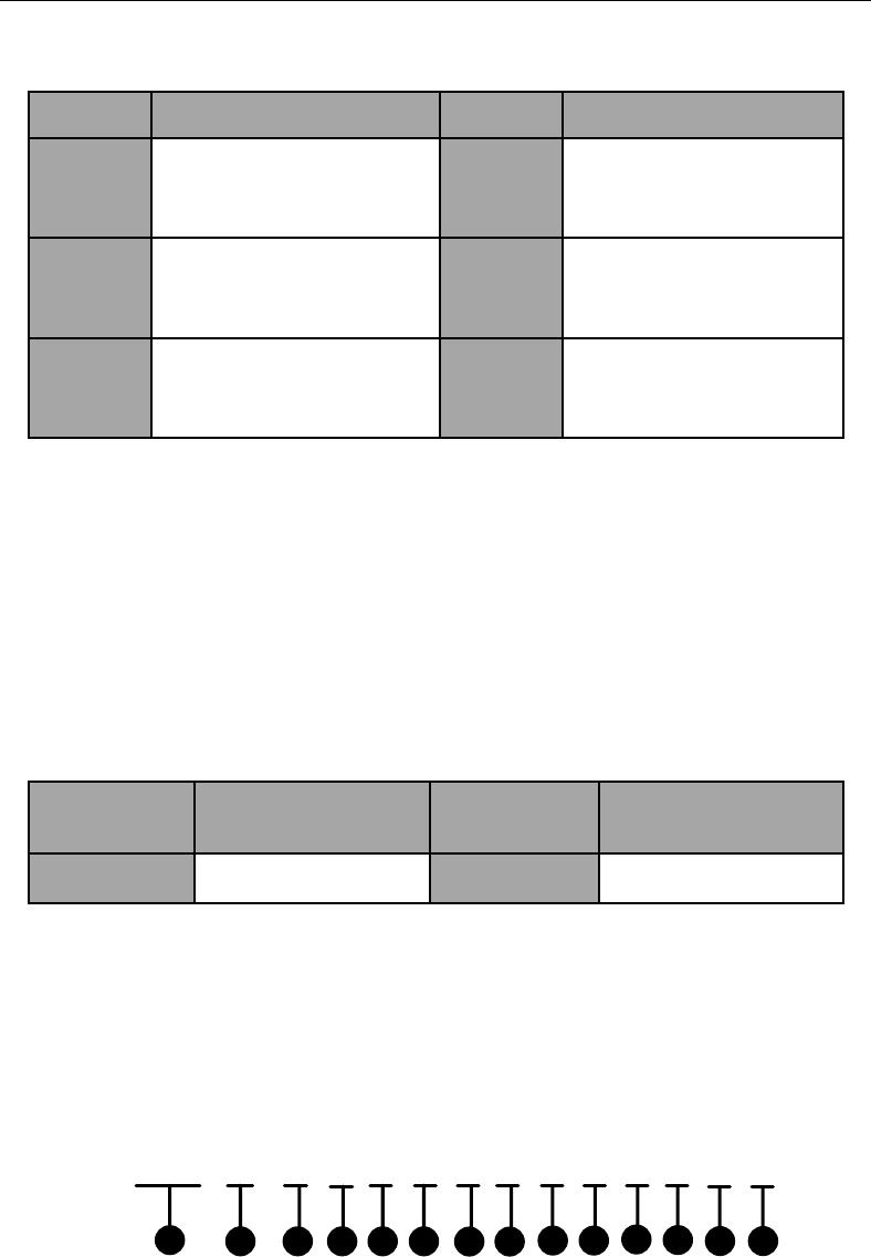
Control Panel User Manual
62
{1} Center Group Non-zone Alarm Report Programming Address: 614, 618, 622, 626,
630and 634.
Command
Command Description
Command
Command Description
614
Center Group1 Non-zone
Alarm Report Programming
Address
618
Center Group 2Non-zone
Alarm Report
Programming Address
622
Center Group3 Non-zone
Alarm Report Programming
Address
626
Center Group 4 Non-zone
Alarm Report
Programming Address
630
Center Group 5 Non-zone
Alarm Report Programming
Address
634
Center Group 6 Non-zone
Alarm Report
Programming Address
{2} Soft Zone Report
{3} System Status Report
{4} Alarm Clearing Report
{5} Testing Report
{6} Arming Report
{7} Disarming Report
{8} Control Panel Duress Reportage
{9} Alarm Recovery Report
{10} Bypass Report
{11} Bypass Recovery Report
{2}~{11}Set the value as 1 to send the report. Set the value as 0 not to send the
report.
Command
Command
Description
Command
Command Description
0
Not Sending
1
Sending
{12} End the command.
3.1.30 Whitelist Parameters Configuration
Non-zone Alarm Report Configuration
To configure the non-zone alarm report, please refer to the command below.
680 00 0 0 0 0 0 0 0 0 0 0 0 #
12 4 63 5 87 910 11 12 13 14
{1} Non-zone Alarm Report Configuration Command Address: 680.
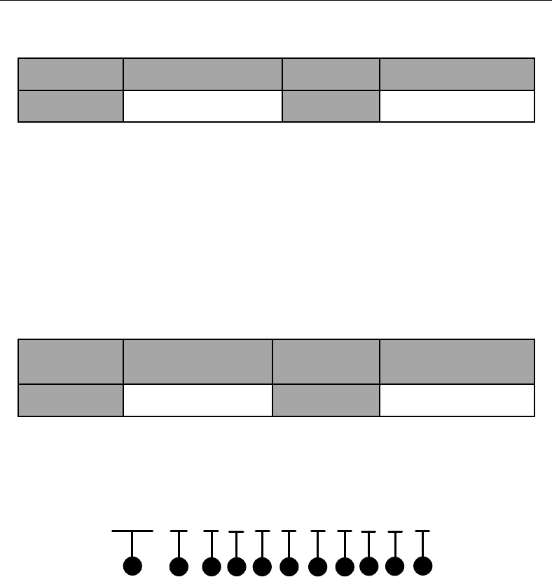
Control Panel User Manual
63
{2} White List Number. 01~08 indicate white list No.1~No.8.
{3} Enable/Disable the Non-zone Alarm Report
Command
Command Description
Command
Command Description
0
Disable
1
Enable
{4} Soft Zone Report
{5} System Status Report
{6} Alarm Clearing Report
{7} Testing Report
{8} Arming Report
{9} Disarming Report
{10} Control Panel Duress Report
{11} Alarm Recovery Report
{12} Bypass Report
{13} Bypass Recovery Report
{4}~{13} Set the value as 1 to send the report. Set the value as 0 not to send the
report.
Command
Command
Description
Command
Command Description
0
Not Sending
1
Sending
{14} End the command.
Partition Arming Permission Configuration
To configure the permission of partition arming, please refer to the command below.
681 00 0 0 0 0 0 0 0 0 #
12 4 63 5 87 910 11
{1} Partition Arming Permission Configuration Command Address: 681
{2} White List Number. 01~08 indicate white list No.1~No.8.
{3} The Arming Permission of Partition 1
{4} The Arming Permission of Partition 2
{5} The Arming Permission of Partition 3
{6} The Arming Permission of Partition 4
{7} The Arming Permission of Partition 5
{8} The Arming Permission of Partition 6
{9} The Arming Permission of Partition 7
{10} The Arming Permission of Partition 8
{3}~{10} Enable/Disable the Permission of Partition Arming
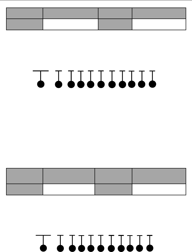
Control Panel User Manual
64
Command
Command Description
Command
Command Description
0
Disable
1
Enable
{11} End the command.
Partition Disarming Permission Configuration
To configure the permission of partition disarming, please refer to the command below.
682 00 0 0 0 0 0 0 0 0 #
12 4 63 5 87 910 11
{1} Partition Disarming Permission Configuration Command Address: 682
{2} White List Number. 01~08 indicate white list No.1~No.8.
{3} The Disarming Permission of Partition 1
{4} The Disarming Permission of Partition 2
{5} The Disarming Permission of Partition 3
{6} The Disarming Permission of Partition 4
{7} The Disarming Permission of Partition 5
{8} The Disarming Permission of Partition 6
{9} The Disarming Permission of Partition 7
{10} The Disarming Permission of Partition 8
{3}~{10} Enable/Disable the Permission of Partition Disarming
Command
Command
Description
Command
Command Description
0
Disable
1
Enable
{11} Completing
Partition Alarm Clearing Permission Configuration
To configure the permission of partition alarm clearing, please refer to the command below.
683 00 0 0 0 0 0 0 0 0 #
12 4 63 5 87 910 11
{1} Partition Alarm Clearing Permission Configuration Command Address: 683
{2} White List Number. 01~08 indicate white list No.1~No.8.
{3} The Alarm Clearing Permission of Partition 1
{4} The Alarm Clearing Permission of Partition 2
{5} The Alarm Clearing Permission of Partition 3
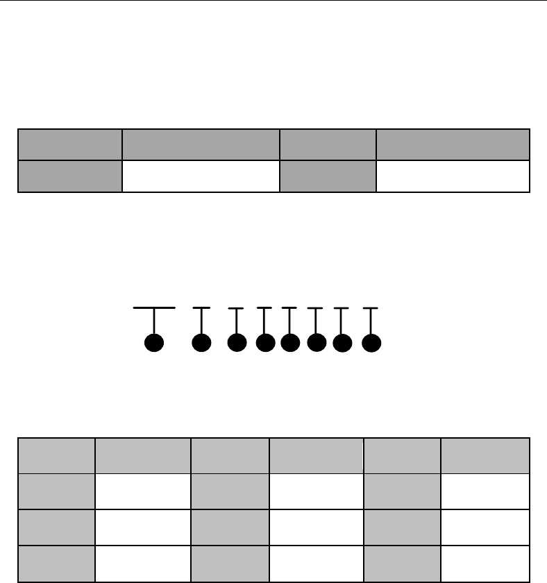
Control Panel User Manual
65
{6} The Alarm Clearing Permission of Partition 4
{7} The Alarm Clearing Permission of Partition 5
{8} The Alarm Clearing Permission of Partition 6
{9} The Alarm Clearing Permission of Partition 7
{10} The Alarm Clearing Permission of Partition 8
{3}~{10} Enable/Disable the Permission of Partition Alarm Clearing
Command
Command Description
Command
Command Description
0
Disable
1
Enable
{11} End the command.
The Interval Time of Whitelist Configuration
To configure the interval time of white list, please refer to the command below.
684 01 0 0 0 0 0 #
1 2 3 54 6 87
{1} The interval time of White List Configuration Command Address: 684.
{2} White List Number. 01~08 indicate white list No.1~No.8.
{3} Interval Time. The command is shown below.
Command
Description
Command
Description
Command
Description
0
0s
1
10s
2
30s
3
1min
4
5min
5
5-10min
6
User Defined
{4} The user defined interval time: Thousands’ Digit
{5} The user defined interval time: Hundreds’ Digit
{6} The user defined interval time: Tens’ Digit
{7} The user defined interval time: Digit
{4}~{7} Valid only when {3} is 6.
{8} End the command.
Handset Number Settings
To configure the handset number, please refer to the command below.
Control Panel User Manual
66
685 01 1 E0 ∙∙∙∙∙∙0 #
1 4 5
2 3
{1} Handset Number Command Address: 685.
{2} White List Number. 01~08 indicate white list No.1~No.8.
{3} Handset No. Segment
Command
Command Description
Command
Command Description
1
The first 16 characters of
the 32 characters
2
The last 16 characters
of the 32 characters
{4} The dialing number is 16 digits.
The letter E at the beginning of {5} can be set as A, indicating “+”.
The length of the each telephone number is 31 digits, and all the telephone
number should be ended with *4.
{5} End the command.
Zone Report Type Configuration
To configure the zone report type, please refer to the command below.
686 01 0 0 0 0 #
1 2 4 6
357
{1} Zone Report Type Configuration Command Address: 686.
{2} White List Number. 01~08 indicate white list No.1~No.8.
{3} Set the value as 1 to send the report. Set the value as 0 not to send the report.
Command
Command Description
Command
Command Description
0
Not Sending
1
Sending
{4} Zone No.: Hundreds’ Digit
{5} Zone No.: Tens’ Digit
{6} Zone No.: Digit
When the Zone No. has no hundreds’ digit, {4} can be omitted.
Example: When you want to send report of Zone No.16. The command is
68601116#.
When the Zone No. has no hundreds’ digit and tens’ digit, {4} and {5} can be
omitted.
Control Panel User Manual
67
Example: When you want to send report of Zone No.8. The command is
6860118#.
{7} End the command.
After operating once, you can continuously configure with the command of {Project} +
{Zone No.} + {#}
3.1.31 Schedule Configuration
Enabling Weekly Schedule
To enable the weekly schedule, please refer to the command below.
690 01 0 0 #
1 4
235
{1} Enabling Weekly Schedule Command Address: 690.
{2} Partition Number, 01~08 indicate partitions No.1~No.8.
{3} Enable/Disable Mandatory Arming
Command
Command
Description
Command
Command Description
0
Disable
1
Enable
{4} It indicates to enable/disable the weekly schedule.
Command
Command
Description
Command
Command Description
0
Disable
1
Enable
{5} End the command.
Weekly Schedule Time Parameter Configuration
To configure the time parameters of the weekly schedule, please refer to the command
below.
691 01 1 1 0 0 0 0 0 0 0 0 E #
12 4 63 5 87 910 11 12 13 14
{1} Weekly Schedule Time Parameter Configuration Command Address: 691.
{2} Partition Number. 01~08 indicate partitions No.1~No.8.
Control Panel User Manual
68
{3} Monday to Sunday
Command
Description
Command
Description
Command
Description
1
Monday
2
Tuesday
3
Wednesday
4
Thursday
5
Friday
6
Saturday
7
Sunday
{4} Time bucket composed by {5}~{12}. The value range is 1~8.
{5}~{12} It indicates the start time and end time during the time bucket of {4}.
Start Time: {5}{6}:{7}{8}
End Time: {9}{10}:{11}{12}
When you set the start and end time as 00:00 and 00:00, all the settings from the
present time bucket to the maximum time bucket will be cleared.
When you set the start and end time as non-zero, the previous time bucket must
be non-zero.
When you set the start and end time as non-zero, only Arming in {13} can be set.
When you set the start and end time as non-zero, end time must be greater than
start time in every time bucket.
When you set the start and end time as non-zero, the start time must be 5min
greater than the end time of the previous time bucket.
When you set the start and end time as non-zero, if the time bucket is overlapped
with the latter ones, or the difference between them is less than 5min, all the
settings of the latter ones will be cleared.
{13} Three types of Arming/Disarming.
Command
Command
Description
Command
Command
Description
Command
Command
Description
A
General
Arming/Dis
arming
B
Real-time
Arming/Disar
ming
C
Stay
Arming/Disar
ming
{14} End the command.
Copying Weekly Schedule
To copy the settings of the day (n) to another day (l) of the week in partition (m), please
refer to the command below.
Control Panel User Manual
69
692 01 0 0 #
1 4
235
{1} Copy Weekly Schedule Command Address: 692.
{2} Partition (m) Number. 01~08 indicate partitions No.1~No.8.
{3} It indicates the value range of the day (n).
Command
Description
Command
Description
Command
Description
1
Monday
2
Tuesday
3
Wednesday
4
Thursday
5
Friday
6
Saturday
7
Sunday
{4} It indicates the value range of the day (l).
Command
Description
Command
Description
Command
Description
1
Monday
2
Tuesday
3
Wednesday
4
Thursday
5
Friday
6
Saturday
7
Sunday
{5} Completing
Copy Weekly Schedule of Partition
To copy the settings of partition (m) to partition (n), please refer to the command below.
693 01 02 #
1 2 3 4
{1} Copy Weekly Schedule of Partition Command Address: 693.
{2} Partition (m) Number. 01~08 indicate partitions No.1~No.8.
{3} Partition (n) Number. 01~08 indicate partitions No.1~No.8.
{4} End the command.
Prior Schedule Date Parameter Configuration
To configure the date parameters of the prior schedule, please refer to the command
Control Panel User Manual
70
below.
694 00 0 0 0 0 0 0 0 0 0 0 #
12 4 63 5 87 910 11 12 13
{1} Prior Schedule Date Parameter Configuration Command Address: 694.
{2} It indicates the prior schedule number. 00~30 indicate prior schedules
No.00~No.30.
{3} It indicates to enable/disable the mandatory arming/disarming.
Command
Command
Description
Command
Command Description
0
Disable
1
Enable
{4} It indicates to enable/disable the prior schedule.
Command
Command
Description
Command
Command Description
0
Disable
1
Enable
{5}~{12} It indicates the start date and end date.
Start Date: {5}{6}/{7}{8}. The former is the month (value range 1~12), while
the latter is the day (value range 1~30).
End Date: {9}{10}/{11}{12}. The former is the month (value range 1~12),
while the latter is the day (value range 1~30).
{5} End the command.
Enabling Prior Schedule
To enable the prior schedule, please refer to the command below.
695 00 0 0 0 0 0 0 0 0 #
12 4 63 5 87 910 11
{1} Enabling Prior Schedule Command Address: 695.
{2} It indicates the prior schedule number. 01~30 indicate prior schedule
No.1~No.30.
{3} Partition 1
{4} Partition 2
{5} Partition 3
{6} Partition 4
{7} Partition 5
{8} Partition 6
{9} Partition 7
Control Panel User Manual
71
{10} Partition 8
{3}~{10} It indicates to enable/disable prior schedule of Partition No.1~No.8.
Command
Command
Description
Command
Command Description
0
Disable
1
Enable
{11} End the command.
Prior Schedule Time Parameter Configuration
To configure the time parameters of the prior schedule, please refer to the command
below.
696 00 0 0 0 0 0 0 0 0 0 E #
12 4 63 5 87 910 11 12 13
{1} Prior Schedule Time Parameter Configuration Command Address: 696.
{2} It indicates the prior schedule number. 01~30 indicate prior schedule
No.1~No.30.
{3} It presents the time bucket composed by {4}~{11}. The value range is 1~8.
{4}~{11} It indicates the start time and end time during the time bucket of {3}.
Start Time: {4}{5}:{6}{7}
End Time: {8}{9}:{10}{11}
When you set the start and end time as 00:00 and 00:00, all the settings from the
present time bucket to the maximum time bucket will be cleared.
When you set the start and end time as non-zero, the previous time bucket must
be non-zero.
When you set the start and end time as non-zero, only Arming in {12} can be set.
When you set the start and end time as non-zero, end time must be greater than
start time in every time bucket.
When you set the start and end time as non-zero, the start time must be 5min
greater than the end time of the previous time bucket.
When you set the start and end time as non-zero, if the time bucket is overlapped
with the latter ones, or the difference between them is less than 5min, all the
settings of the latter ones will be cleared.
{12} Three types of Arming/Disarming.
Command
Command
Description
Command
Command
Description
Command
Command
Description
A
General
Arming/Dis
arming
B
Real-time
Arming/Dis
arming
C
Stay
Arming/Disar
ming
Control Panel User Manual
72
{13} End the command.
Enabling Relay Schedule
To enable the relay schedule, please refer to the command below.
697 0 #
1 2 3
{1} Enabling Relay Schedule Command Address: 697.
{2} It indicates to enable/disable the relay schedule.
Command
Command Description
Command
Command Description
0
Enable
1
Disable
{3} End the command.
Relay Schedule Relay Parameter Configuration
To configure the relay parameters of the relay schedule, please refer to the command
below.
698 0 0 0 0 #
1 2 4 63 5
{1} Relay Schedule Relay Parameter Configuration Command Address: 698.
{2} It indicates to delete/add the relay schedule.
Command
Command Description
Command
Command Description
0
Delete
1
Add
{3} Relay No.: Hundreds’ Digit
{4} Relay No.: Tens’ Digit
{5} Relay No.: Digit
{6} End the command.
Relay Schedule Time Parameter Configuration
To configure the time parameters of the relay schedule, please refer to the command
below.
Control Panel User Manual
73
699 0 0 0 0 0 0 0 0 0 E #
12 4 63 5 87 910 11 12
{1} Relay Schedule Time Parameter Configuration Command Address: 699.
{2} It presents the time bucket composed by {3}~{10}. The value range is 1~8.
{3}~{10} It indicates the start time and end time during the time bucket of {2}.
Start Time: {3}{4}:{5}{6}
End Time: {7}{8}:{9}{10}
When you set the start and end time as 00:00 and 00:00, all the settings from the
present time bucket to the maximum time bucket will be cleared.
When you set the start and end time as non-zero, the previous time bucket must
be non-zero.
When you set the start and end time as non-zero, only Enable in {11} can be set.
When you set the start and end time as non-zero, end time must be greater than
start time in every time bucket.
When you set the start and end time as non-zero, the start time must be 5min
greater than the end time of the previous time bucket.
When you set the start and end time as non-zero, if the time bucket is overlapped
with the latter ones, or the difference between them is less than 5min, all the
settings of the latter ones will be cleared.
{11} Enable/disable the relay schedule.
Command
Command
Description
Command
Command Description
A
Enable
B
Disable
{12} End the command.
3.1.32 Wireless User Permission Configuration
To configure the permission of wireless users, please see the command below.
701 1 1 1 1 1 #
1 2 463 5 7
{1} Wireless User Permission Configuration Command Address: 701~732. 701~732
indicate wireless users No.1~No.32.
{2} Arming
{3} Arming Report
Control Panel User Manual
74
{4} Disarming
{5} Disarming Report
{6} Alarm Clearing
{2}~{6}
Command
Command Description
Command
Command Description
0
Supported
1
Unsupported
{7} End the command.
3.2 Keypad Alarm Operation Code
3.2.1 Device Initialization
Control panel can be recovered through the alarm keypad initialization; see the command
below.
{Installer Code} + {*} + {8} + {9} + {#}
The default password for the installer:012345.
When doing initialization for the device, the No.1 partition is enabled by default and
the partition-system mode of the global keypad cannot be switched to the global
mode. When a non-No.1 partition is enabled, the global mode of the system will be
enabled automatically.
3.2.2 Control panel Arming and Disarm
The operation of control panel arming and disarming is the same. Take the password 1234
as an example, and the command is shown below.
{1} +{2} + {3} +{4} +{#}
After the operation is completed, the arming status of the control panel will be changed
(the status of arming will be exchanged into disarming), vice versa.
Operation method: {User password} + {*} + {1} + {7} + {#}.Take the password 1234 as an
example, and the command is shown below:
{1} + {2} + {3} + {4} + {*} + {7} + {#}
After the operation is completed, the partition will change the status of disarming (current
status) into arming immediately. The exiting delay of partition is 0.
3.2.3 Stay Arming
Operation Method: {User password} + {*} + {4} + {#}.Take the password 1234 as an

Control Panel User Manual
75
example, and the operation is shown as follows:
{1} + {2} + {3} + {4} + {*} + {4} + {#}
After the operation is completed, the partition will change the status of disarming (current
status) into arming immediately. The bypass-supported zone of the partition will do
auto-bypass simultaneously.
3.2.4 Zone Bypass/Recovery
After bypassing a zone, all the alarm devices in this zone will be blocked. ; see the command
below
{User password} + {bypass} + {Zone Number} + {#}
For continuous bypass/ recovery; see the command below:
[1234] [1]
[Bypass][#]
+
+
+[2][Bypass] [#]
++ [Bypass][ # ]
++[ 8]
……
15 Seconds
Continuous operation of multi-zone bypass/ recovery should be completed within 15
seconds
3.2.5 Group Bypass
After a partition is conducted with group bypass, all the alarm devices in group-bypass
supported zone of the partition will be blocked. See the command below.
{User Password} + {*} + {4} + {1} + {#}
3.2.6 Group Bypass Recovery
After recovering the group bypass of a partition, all the alarm devices in group-bypass
supported zone of the partition will be revalidated. See the command below.
{User Password} + {*} + {4} + {2} + {#}
3.2.7 Canceling Keypad Alarm
When the alarm is trigged, it can be canceled by keypad. The alarm can be canceled both
under the arming and the disarming status.
Alarm Clearing under the Arming Status
Operation Method: {User Password} + {*} + {1} + {#}
Alarm clearing under the disarming Status
Control Panel User Manual
76
Operation Method (1): {*} + {1} + {#}
Operation Method(2): {Users Password} + {*} + {1} + {#}
3.2.8 Alarm Output Operation
For enabling alarm output of the alarm keypad, see the command below.
{Password} + {*} + {8} + {5} + {n} + {#}
For disabling alarm output of the alarm keypad, see the command below.
{Password} + {*} + {8} + {6} + {n} + {#}
The control panel supports 16 channels of alarm outputs, the N valuation should be 1-16.
3.2.9 Emergency Alarm
Press the {PANIC} button on the alarm keypad for 3 seconds or more. The emergency alarm
will be triggered after a double-beep sound.
3.2.10 System Status Query
In query mode, there are special meanings (see the table below) for the 8 indicators on
alarm keypad. Press the {Status} key for current system information Query.
Serial
Number
Meaning
Serial
Number
Meaning
1
AC Power Loss
5
Keypad
Disconnection
2
Low Battery
6
Network
Disconnection
3
Tampering
Alarm
Enabling
7
GPRS Exception
4
Telephone
line
Disconnection
8
Expansion Bus
Exception

Control Panel User Manual
77
3.2.11 Control Panel and Wireless Device Connection
The steps of connecting wireless device with the control panel are shown as follows.
1. Enter the command of {password} + {*} + {91} + {wireless device
No.} + {#} with the RF keypad to enter the connection mode.
2. Press any key on the keyboard to complete the connection.
3.2.12 Deleting the Specified Connected Wireless Device
Follow the command below to delete the connected wireless device.
{password} + {*} + {90} + {wireless device No.} + {#}
3.2.13 Deleting all the Connected Wireless Device
Follow the command below to delete all the connected wireless devices.
{password} + {*} + {92} + {#}
3.2.14 Main Operator Password Changing
The user password can be changed by main operator. The operations are divided into
following steps:
Steps:
1. {Master Code} } + {*} + {0} + {#}
2. {User Number} + {#}
3. {New Password} +{#}
4. {New Password}+{#}
The password will be changed by the above four steps
The User Number must be expressed into three digits, such as 002.
3.2.15 Control Programming Operation
The control panel can be configured via alarm keypad operation; configuration process is
generally divided into three steps:
Steps:
1. Enter the programming mode; see the command below:
{Installer Code} + {*} + {0} + {#}
2. Control panel configuration operation (see section 4.1)
3. Exit programming mode; see the command below:
{*} + {#}

Control Panel User Manual
78
3.2.16 Entering Partition
See the command below to enter the partition.
{*} + {3} + {n} + {#}
3.2.17 Alarm Center Test
Partition keypad operation is used to test the communication between control panel and
the alarm center; see the command below:
{password} + {*} + {6} + {1} + {#}
One operation generates one test report. It is used to test the communication between the
control panel and center after installing the system or during the inspection.
3.2.18 Project Mode
Enter the project mode to debug alarm control panel; see the command below:
{password} + {project} + {9} + {0} + {n} + {#}
Long press {Project} / {State} or {*} {#} key to exit the project mode after debugging.
When the evaluation of n is 1 or 2, the handset 1 and 2 are in dialing status.
When the evaluation of n is 3 or 4, the network center1 and 2 are in uploading status.
When the evaluation of n is 5 or 6, the GPRS center is 1 and 2 are in uploading status.
3.2.19 Enabling/Disabling Key Tone
For keypad tone status switch, see the command below:
{*} + {5} + {1} + {#}
3.2.20 LCD Backlight Control
For LCD backlight control; see the command below:
{*} + {5} + {2} + {n} + {n} + {n} + {#}
{n}{n}{n}refers to the light duration in seconds, and 999 means the LCD is always light
The default duration is 900 seconds, and the parameters will be restored after reboot.
3.2.21 LCD Backlight off
For Disabling the LCD backlight, see the command below:
{*} +{8} + {#}

Control Panel User Manual
79
3.2.22 Pacing
The pacing function is used for debugging; see the command below:
{password} + {*} + {6} + {0} + {#}
The function of pacing is only available under the status of disarming and non-fault of
the zone. The system will do auto-arming in the pacing mode without reporting any CID
log. The siren will start warning after the alarm is triggered and stop warning if the
alarm is dismissed.
If the zone is disarmed, it will exit the pacing mode automatically.
3.2.23 SMS Arming/Disarming
The control panel supports SMS arming/disarming, the command is shown below:
Away arming for the partition
{121} +{#} +{Partition No.} + {#}
Instant arming for the partition
{122} +{#} +{Partition No.} + {#}
Stay arming for the partition
{123} +{#} +{Partition No.} + {#}
Partition disarming
{120} +{#} +{Partition No.} + {#}
Partition alarm clearing
{#} +{100} +{#} +{Partition No.} + {#}
The partition No. is with three digits. for example. If the partition No. is 1. The
command of partition alarm clearing is {#} +{100} +{#} +{001} + {#}
3.2.24 Control Panel Soft Recovery
For control panel soft recovery; see the command below:
{master code} + {*} + {6} + {8} + {#}
All unissued CID logs will not be reissued. Newly generated report will be issued after
system recovery.
The timer of the test report will not be cleared, and will remain the value before
recovery till the recovery processes being completed.

Control Panel User Manual
80
3.2.25 Current Fault Tone Disabling
To disable the current fault tone; see the command below:
{*} + {5} + {6} + {#}
If there are new faults, the prompt sound will re-Tip.
3.2.26 Test Report Manually Relaying
To relay test report manually; see the command below:
{password} + {*} + {6} + {1} + {#}
One operation generates one test report. It is used to test the communication between the
control panel and center after installing the system or during the inspection.
3.2.27 Keypad Locking and Unlocking
If a user failed to operate for five times, the keypad will be locked for 30 seconds. During
the lock duration, the keypad backlight blinks and all of the key operations are invalid. The
keypad will be unlocked after 30 seconds.
3.2.28 Exiting the Operation
See the command below to exit the operation.
{*}{#}
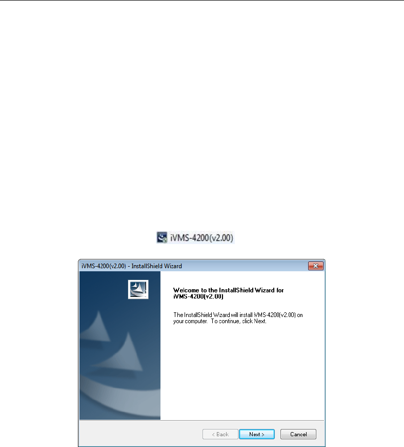
Control Panel User Manual
81
Chapter 4 Accessing by Client
Software
Check the package contents and make sure that the device in the package is in good
condition and all the assembly parts are included.
4.1 Installing the iVMS-4200
Insert the installation media of iVMS-4200 into the appropriate computer.
Perform the following steps to install the iVMS-4200 client software.
1. Double-click the program file to enter the welcome panel of the
InstallShield Wizard. Click Next to start the InstallShield Wizard.
2. Read the License Agreement. Click Print if you want to print the license agreement.
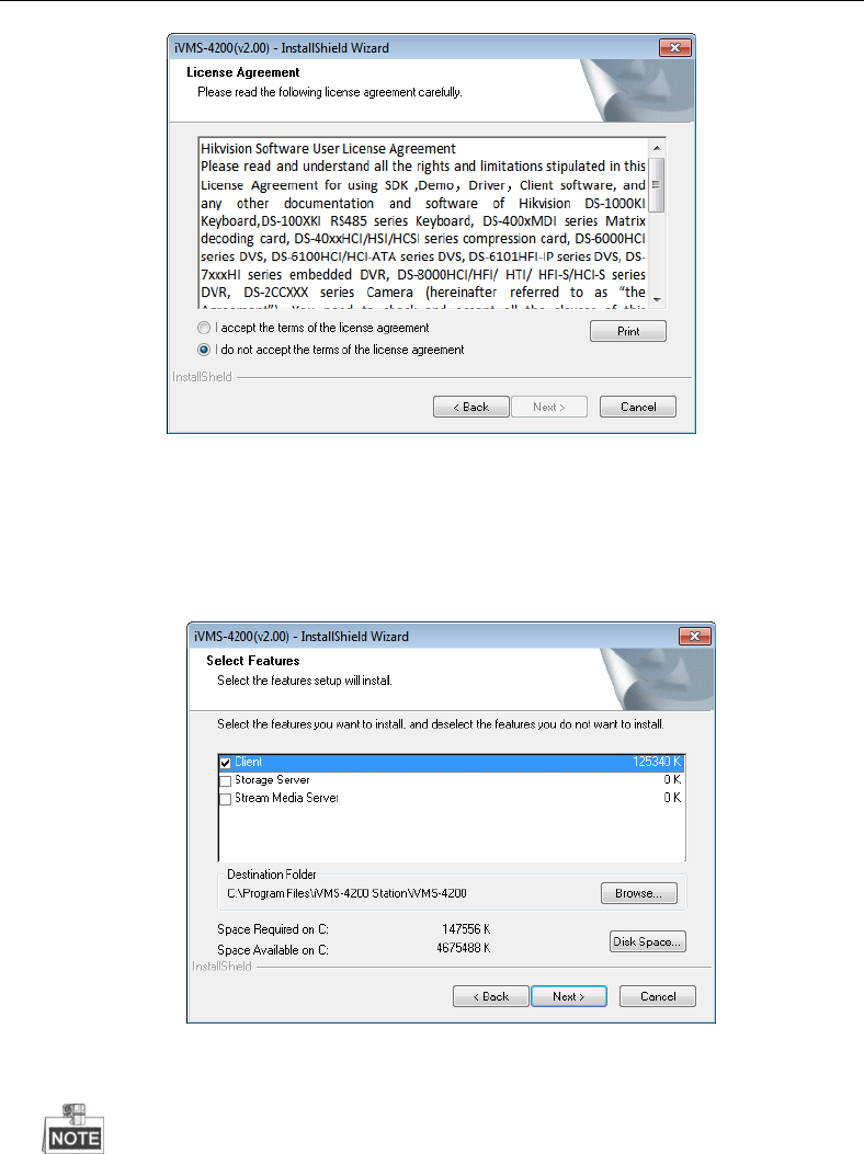
Control Panel User Manual
82
If you accept the terms of the license agreement, click I accept the terms of license
agreement.
Click Next to continue.
Otherwise click I do not accept the terms of the license agreement, and then click Cancel
to cancel the installation
3. On the next panel , you are prompted to select the function module to install.
Set installation directory where the client software is to be installed. You can either accept
the default directory that is displayed, or click Browse and select a different directory.
The default directory is C:\Program Files\iVMS-4200 Station\iVMS-4200.
Click Next to continue.
4. Install the WinpCap plug-in according to the prompts to detect the online devices when
running the client software.
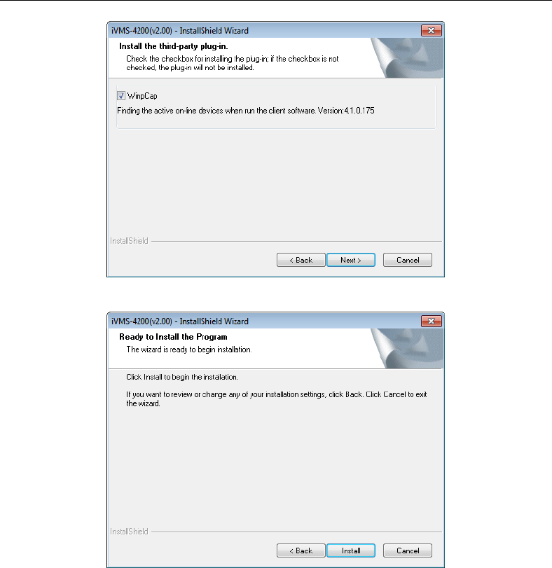
Control Panel User Manual
83
5. Read the pre-install information and click Install to begin the installation.
6. A panel indicating progress of the installation is displayed. A percentage completion bar is
updated as the installation progresses.
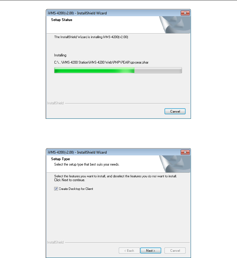
Control Panel User Manual
84
7. Select the setup type according to your need.
You can check the checkbox of Create Desktop for Client to create a shortcut icon on the
desktop for the client software.
8. Read the post-install information and click Finish.
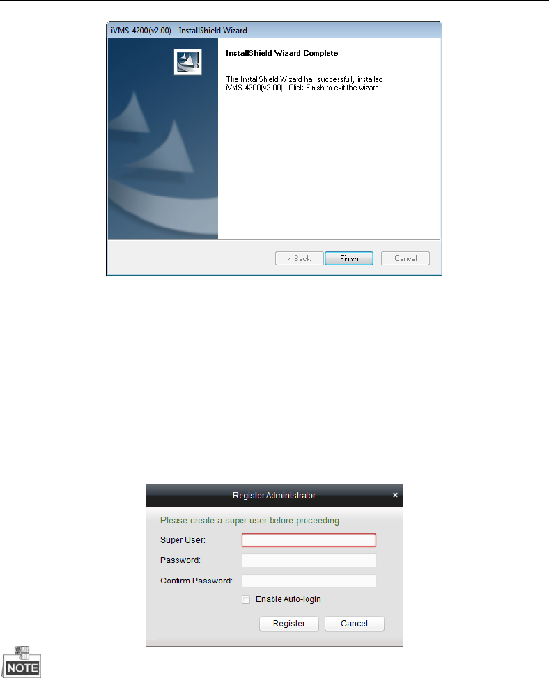
Control Panel User Manual
85
4.2 User Registration and Login
For the first time to use iVMS-4200 software, you need to register a super user for login.
Steps:
1. Input the super user name and password.
2. Confirm the password.
3. Optionally, check the checkbox of Enable Auto-login to log in the software automatically.
4. Click Register. Then, you can log in the software as the super user.
A user name cannot contain any of the following characters: / \ : * ? “ < > |
The password cannot be empty and the length of the password should be no less than
six characters.
When opening iVMS-4200 after registration, you can log in the software with the registered user
name and password.
Steps:
1. Input the user name and password you registered.
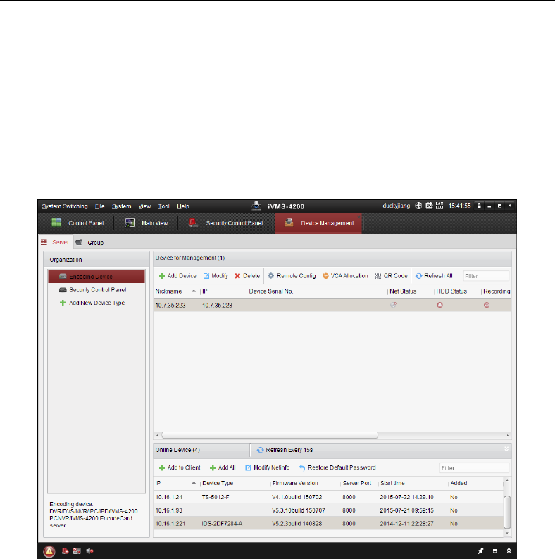
Control Panel User Manual
86
2. Optionally, check the checkbox of Enable Auto-login to log in the software automatically.
3. Click Login.
4.3 Network Security Control Panel Settings
Purpose:
In this section, you are able to configure or view the basic parameters (such as the system
information, alarm information, network data, device status and so on) of the security
control panel.
Click Tool>Device Management to enter the interface
4.3.1 Add/Edit/Delete the Device
Add a Device:
Steps:
1. Select Security Control Panel as the device type on the Organization list.
2. Click Add Device to open the device adding dialog box.
3. Select IP/Domain as the adding mode.
4. Input the required information.
Nickname: Edit a name for the device as you want.
Address: Input the device’s IP address or domain name.
Port: Input the device port number. The default value is 8000.
User Name: Input the device user name.
Password: Input the device password.
5. Optionally, you can check the checkbox Export to Group to create a group by the device
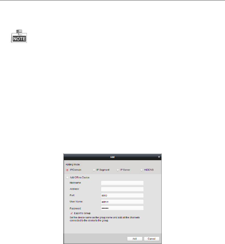
Control Panel User Manual
87
name. All channels and alarm inputs of the device will be imported to the corresponding
group by default.
6. Click Add to add the device.
For first time adding the control panel, you need to add Security Control Panel to the
organization as a new device type.
Steps:
1. Click Add New Device Type to enter the interface.
2. Check the checkbox of Security Control Panel.
3. Click OK to complete the settings.
Edit a Device
Purpose:
You can edit the device information in this section, including the device name, address and
port number.
Steps:
1. On the Device Management interface, click and select a control panel in the device list.
2. Click on the Modify button on the upper side of the list to enter the device modify
interface.
3. Enter the required nick name, address, and port number and then enter the admin
username and password.
4. Click Modify to save the changes.
Delete a Device
Select device from the list, click Modify/Delete, and then you can modify/delete the
information of the selected device.
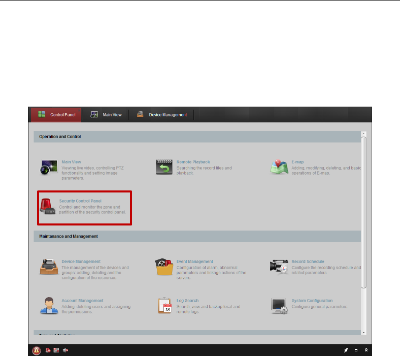
Control Panel User Manual
88
4.4 Security Control Panel Remote Control
In this section, you can control the panel remotely to implement operations such as arming,
disarming, bypass, group bypass, and so on for both the partitions and zones.
Click View>Control Panel to enter the main control panel of the client
In the main Control Panel of the client, Click Security Control Panel to enter the interface.
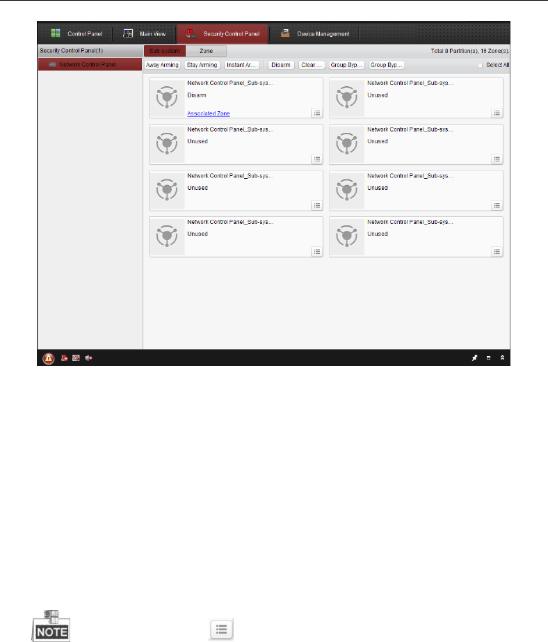
Control Panel User Manual
89
4.4.1 Partition Remote Control
In this section, you can remotely implement operations of away arming, stay arming,
instant arming, disarming, clearing alarm, group bypass, and recovering group bypass for
the configured partitions.
Steps:
4. On the Partition (Sub-system) page, click and select one or more partitions to be
controlled, or check the check box of Select All on the upper-right side of the page to
select all partitions.
5. Click the operations buttons (away arming, stay arming, instant arming, disarming,
clearing alarm, group bypass, and group bypass recovery) on the upper side of the
page.
You can also click the icon to get the operation menu for each partition.
3. Click Associated Zone to view the zones of the current partition.
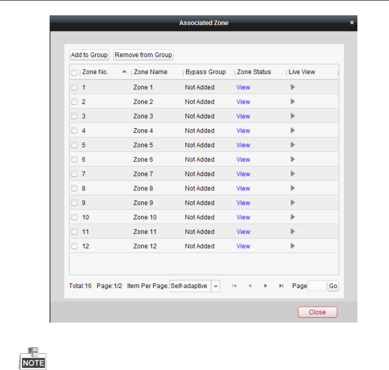
Control Panel User Manual
90
You can add/remove the selected zones into/from the group.
Click View, and you can view the status of the zone.
The function of Live View is only supported by the security control panel with
video input module.
4.4.2 Zone Remote Control
In this section, you can remotely implement bypass, or recovering bypass for the zones.
Steps:
1. Click Zone tag to enter the interface.
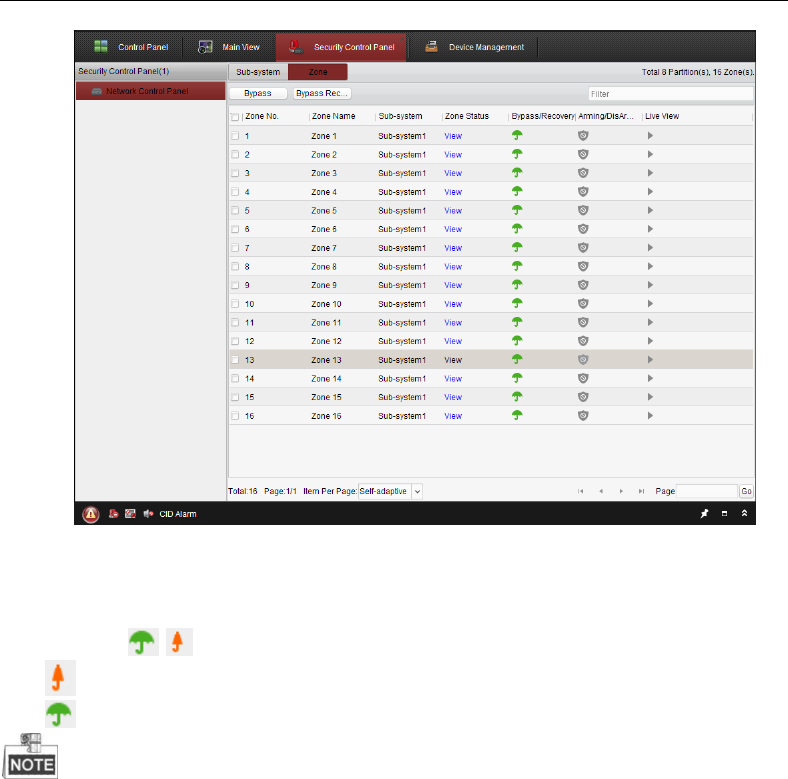
Control Panel User Manual
91
2. Click and select one or more zones to be controlled.
3. Click Bypass/Bypass Recovery on the upper side of the page to control the selected
zones.
4. Click View, and you can view the status of the zone.
5. Click the / icon to bypass or recover a zone separately.
: the zone is bypassed.
: the zone is recovered.
The function of Live View is only supported by the security control panel with video
input module.
4.5 Remote Configuration
Purpose:
In this section, you are able to configure device parameters remotely.
Click the Remote Configuration button to enter the interface.
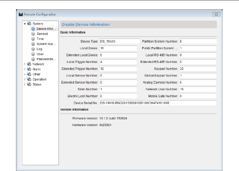
Control Panel User Manual
92
4.5.1 System Information Configuration
Purpose:
In this section, you can configure the system parameters (such as time, log, user, security,
system maintenance and so on) for the device.

Control Panel User Manual
93
Timing Configuration
Before You Start:
Before you start configuring the security control panel, you need to do timing for the device
first.
Enter Remote Configuration>System->Time to get the configuration page. Click the
Synchronization button to complete the settings.
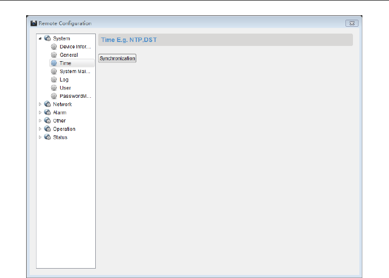
Control Panel User Manual
94
User Configuration
Purpose:
You can add, edit, or delete the network operator and keypad operator in this section.
Network User
Add a Network User
Steps:
1. Enter the user configuration interface.
Remote Configuration->System->User
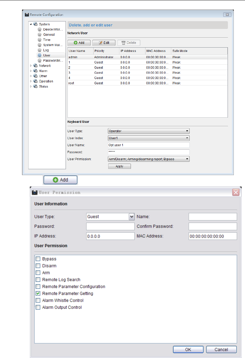
Control Panel User Manual
95
2. Click to enter the interface of adding a network user.
3. Enter the corresponding user information including the user type, user name,
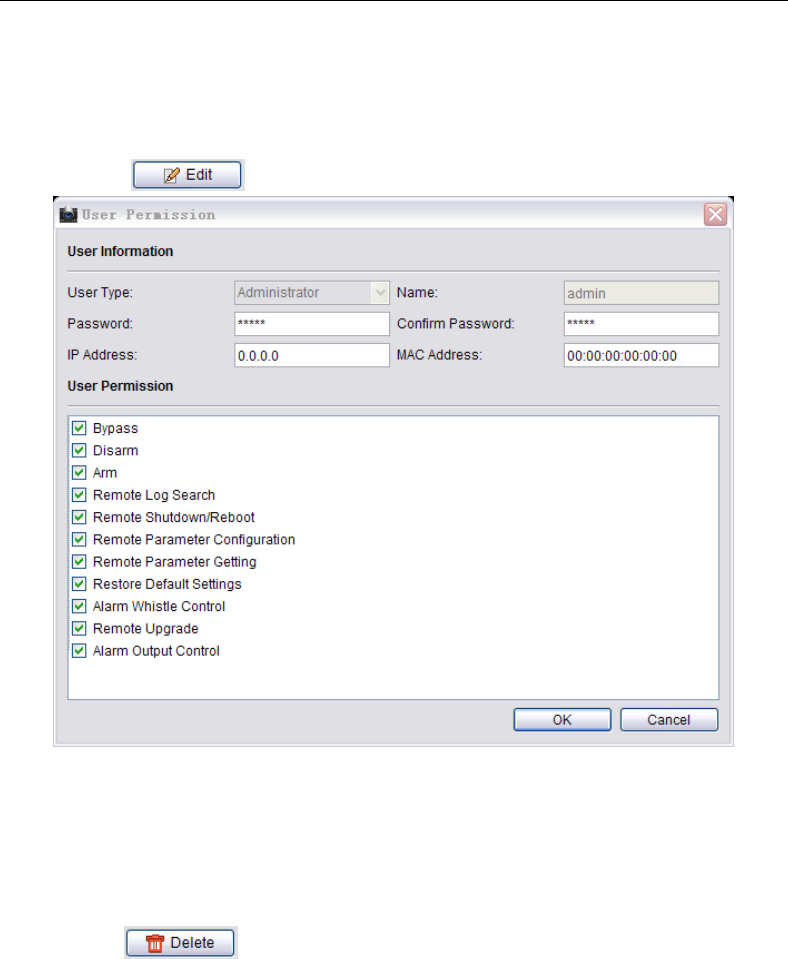
Control Panel User Manual
96
password, IP address, and MAC address.
4. Select the permission of the user.
5. Click OK to finish the settings.
Edit a User
Steps:
1. Click to enter the interface of editing the selected user.
2. Edit the corresponding user information including the user type, user name,
password, IP address, and MAC address
3. Edit the permission of the user.
4. Click OK to finish the settings.
Delete a user
Steps:
1. Select a user needs to be deleted.
2. Click to delete the user.
Keypad User
The control panel supports at most 16 keypad operators.
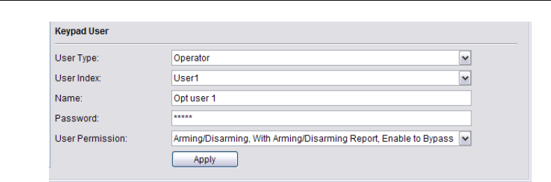
Control Panel User Manual
97
Steps:
1. Select the user type. Operator and installer can be selected.
2. Select the index number of the keypad user, up to 16 numbers can be selected.
3. Enter the name of the keypad operator.
4. Enter the password of the operator.
5. Click the dropdown menu to select the user permission.
6. Click Apply to save the settings.
4.5.2 Network Configuration
Purpose:
You can edit the general network parameters in this section.
General Network Parameters Configuration
Steps:
1. Enter the general network configuration page.
Remote Configuration-> Network->General
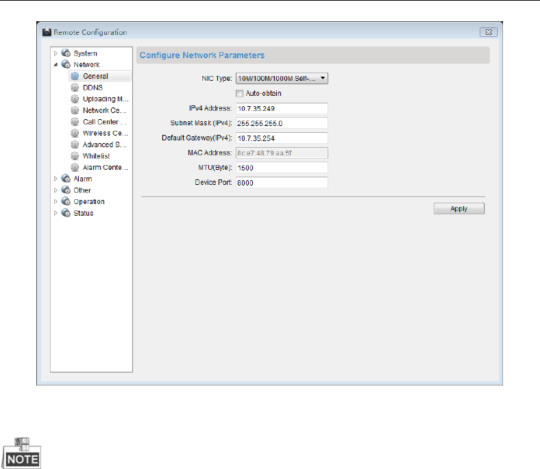
Control Panel User Manual
98
2. Configure the NIC settings, including the IPv4(IPv6) Address, IPv4(IPv6) Subnet Mask
and IPv4(IPv6) Default Gateway.
3. Click Apply to save the above settings.
The valid value range of Maximum Transmission Unit (MTU) is 500 ~ 9676. The default
value is 1500.
The Multicast sends a stream to the multicast group address and allows multiple clients
to acquire the stream at the same time by requesting a copy from the multicast group
address.
Before utilizing this function, you have to enable the Multicast function of your router
and configure the gateway of the control panel.
DDNS Configuration
Purpose:
If your control panel is set to use PPPoE as its default network connection, you can use the
Dynamic DDNS for network access.
Before you start:
Registration on the DDNS server is required before configuring the DDNS settings of the
control panel.
Steps:
1. Enter the DDNS Settings interface:
Remote Configuration> Network > DDNS
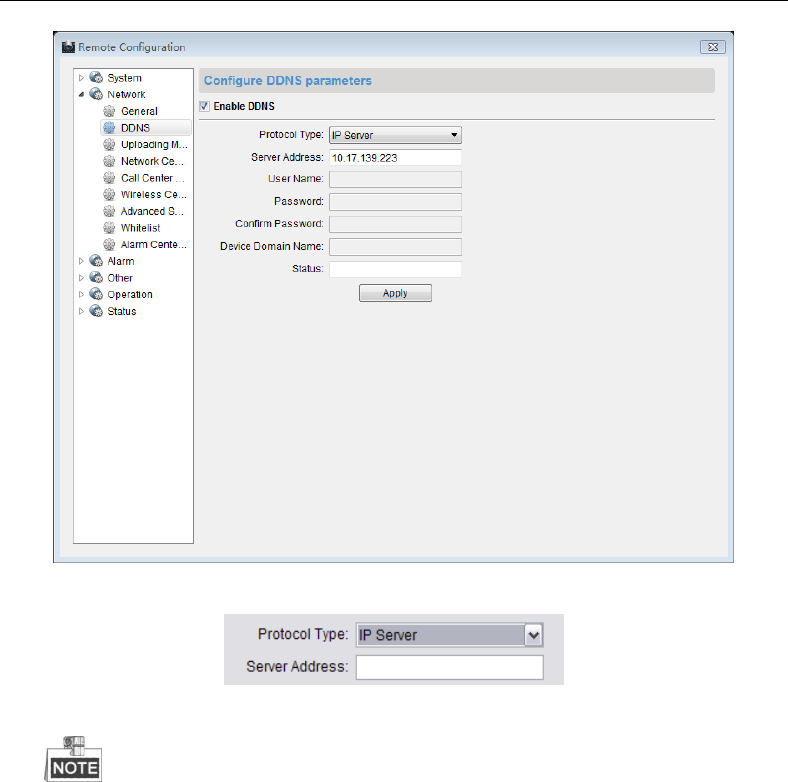
Control Panel User Manual
99
2. Check the Enable DDNS checkbox to enable this feature.
3. Select DDNS Type.
4. Enter the Server Address of the IP Server.
5. Click Apply to save the settings.
The Server Address should be entered with the static IP address of the
computer that runs the IP Server software. For the IP Server, you have to apply
a static IP, subnet mask, and gateway and preferred DNS from the ISP.
Uploading Mode Configuration
Purpose:
You can select to send Zone report, alarm report and configure the uploading mode of the
selected center group in this section.
Steps:
1. Enter the uploading mode configuration page.
Remote Configuration->Uploading Mode Settings
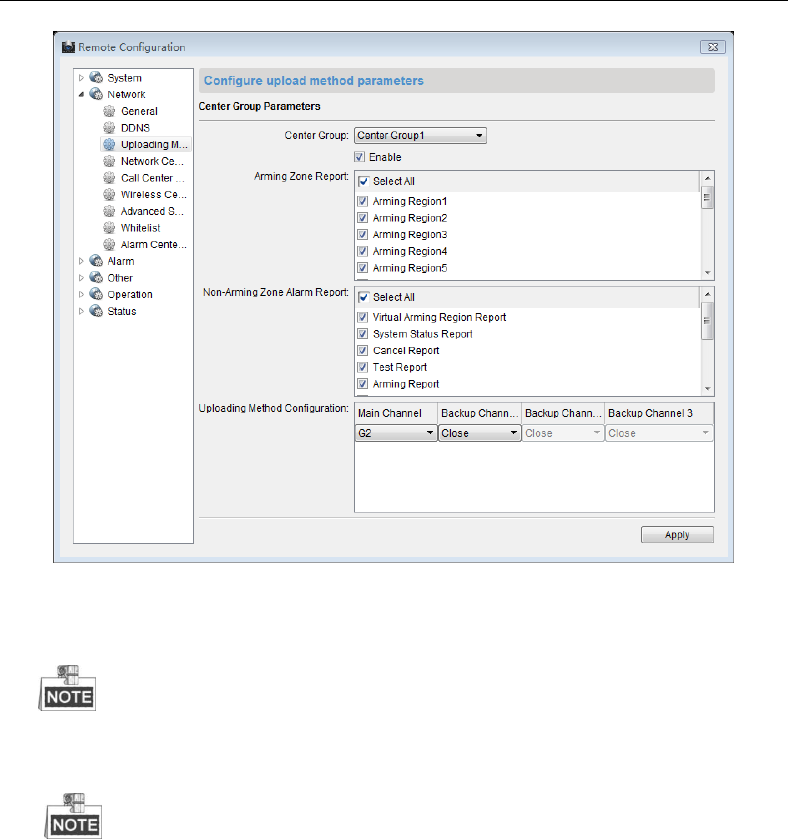
Control Panel User Manual
100
2. Click the drop down menu to select a center group.
3. Check the Enable checkbox to enable the configuration
4. Check the checkbox to select the required Zone for sending the Zone report for the
Zones without Zone report.
At most 6 center groups can be inter-combined to send the alarm report.
5. Check the checkbox to select the type of non-Zone alarm report.
6. Click each dropdown menu to configure the uploading channel.
7. Click Apply to save the settings.
The alarm channel of each center group should be configured in order.
Network Center Configuration
Purpose:
In this section, you can configure the parameters(such as server type, IP address, port
No.,and so on)of the network center.
Steps:
1. Enter the network center configuration page.
Remote Configuration->Network Center
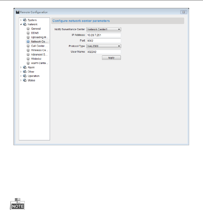
Control Panel User Manual
101
2. Click and select a network center. Two centers are selectable.
3. Click the dropdown menu to select a sever type. Two sever types are available: IP4/IP6
and domain.
4. Enter the IP address that is used to communicate with the network alarm receiving
center.
5. Enter the port No. for communicating with the alarm-receiving center.
6. Click the dropdown menu to select the protocol type.
7. Enter the username that is applying for displaying in the alarm-receiving center.
The length of the username should be 6 characters.
Only numeric (0~9), and letter (A~F&a~f) are valid for this username.
Dialing Center Configuration
Purpose:
You can configure the parameters(such as report uploading time period, center name,
phone number and so on) for each dialing center in this section.
Steps:
1. Enter the dialing center configuration page.
Remote Configuration->Call Center
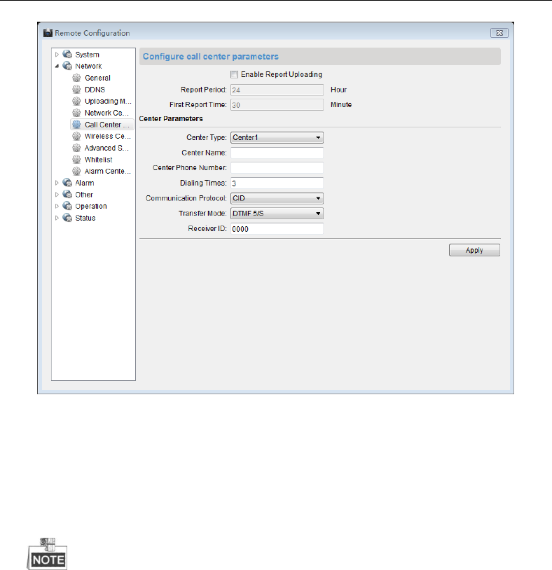
Control Panel User Manual
102
2. Check the checkbox to enable report uploading.
3. Enter the report-uploading period (unit: hour). The report-uploading period represents
the time interval between uploading the first report and the next report.
4. Enter the first report uploading time interval (unit: minute). The first report uploading
time interval represents the time interval between enabling the report uploading
function and sending the first report.
5. Select a center type.
6. Enter the center name and phone number.
The maximum length of center name is 32 characters.
The phone number should be 31 characters and the input mode is
{No.}{Dwell Time}{EXT No.}. For example, in the number of
000088075998FFF8180, the letter F (which means 2 seconds) represents the
dwell time, if the number of the letter F is N, the dwell time is N*F seconds.
The number of F is suggested to be more than 3, which means the dwell
time should be more than 6 seconds.
7. Enter the dialing times (1~15). The dialing times represents the times that the control
panel trying to communicate the alarm receiving center.
8. Select the Pstn protocol.
9. Select the Pstn transmission mode: DTMF5/S and DTMF10/S.
10. Enter the receiver ID which is the authentication account while doing the
communication with the alarm receiving center.
11. Click Apply to save the settings.
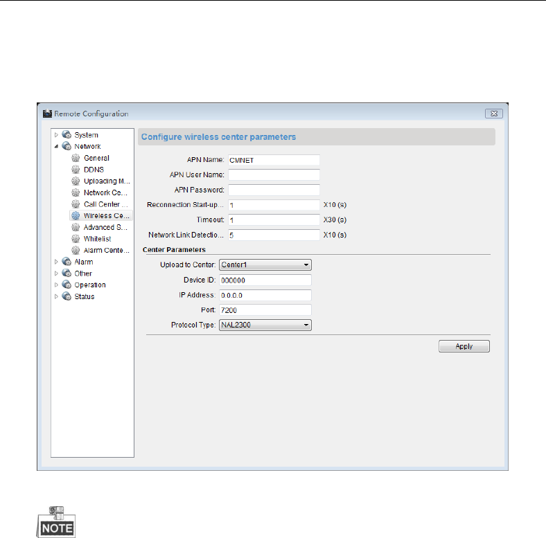
Control Panel User Manual
103
Wireless Center Parameter Settings
Steps:
1. Enter the wireless center parameter settings page.
Remote Configuration->Network->Wireless Center
2. Click the dropdown menu to select the net center.
3. Enter the device ID which is applying for displaying in the alarm receiving center.
The length of the username should be 6 characters.
Only numeric (0~9), and letter (A~F&a~f) are valid for this username.
4. Enter the IP address that is used to communicate with the wireless alarm receiving
center.
5. Enter the port No. for communicating with the alarm receiving center.
6. Click the dropdown menu to select the protocol type.
7. Click Apply to save the settings.
Advanced Network Parameters Settings
Steps:
1. Enter the advanced network configuration page.
Remote Configuration->Network->Advanced Settings
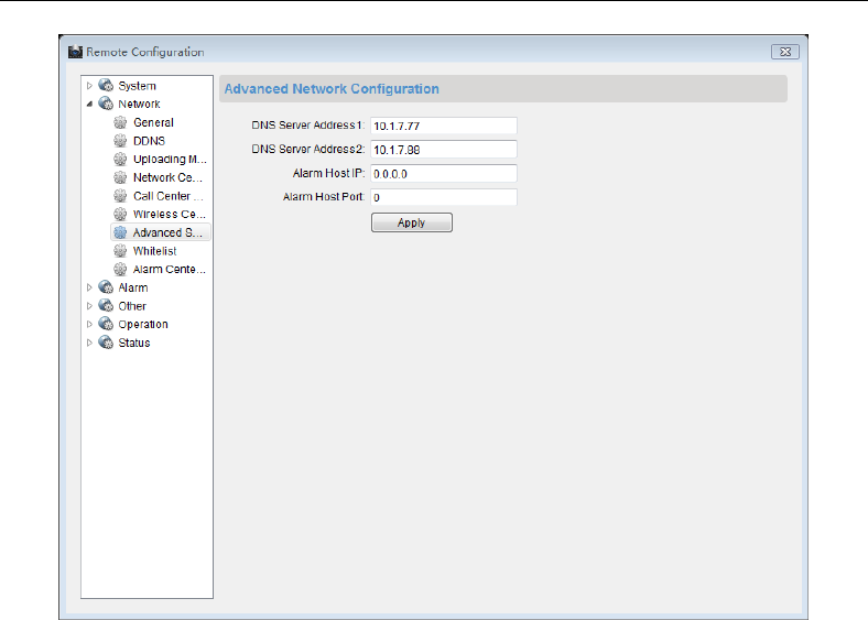
Control Panel User Manual
104
2. Enter the corresponding DNS sever address.
3. Enter the IP address and port No. of the control panel.
4. Click Apply to save the settings.
Whitelist Configuration
Purpose:
The whitelist is the list of phone numbers which are authorized to interact with the control
panel.
Steps:
1. Enter the whitelist configuration interface.
Remote Configuration->Network->Configure Whitelist
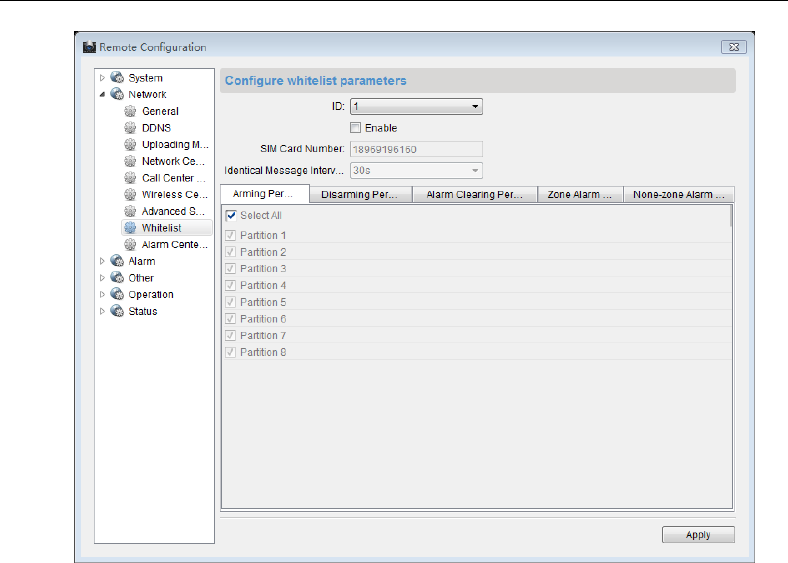
Control Panel User Manual
105
2. Select the index of the whitelist.
3. Check the Enable checkbox to enable the configuration.
4. Enter the phone number of the whitelist into the SIM Card Number text box.
5. Select the identical message time interval that represents the interval of sending
message triggered by the same event.
6. Select the permission of the whitelist on the permission panel.
7. Click Apply to save the settings.
4.5.3 Alarm Configuration
Partition Configuration
Purpose:
You can configure the detailed alarm parameters of the zone in the partition in this section.
Steps:
1. Enter the partition alarm triggering configuration interface.
Remote Configuration->Alarm->Partition
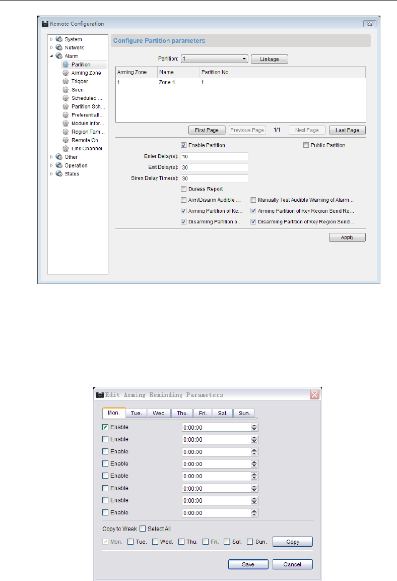
Control Panel User Manual
106
2. Click the partition dropdown menu to select a partition.
3. Click the Linkage button to add required Zone, keypad, or keypad user to the partition.
4. Check the check box of Enable Partition or Public Partition to enable functions of the
partition or set the system as a public system.
5. Enter the Entering Delay and Existing Delay duration (unit: second).
6. Enter the siren-delay time (unit: second). The siren-delay time represents the duration
of siren ringing when the alarm of the partition is triggered.
7. Click Edit to edit the arming schedule. Select the alarm type.
8. Select an alarm type.
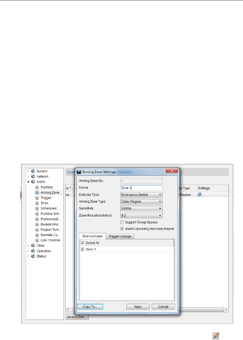
Control Panel User Manual
107
Duress Report: Enable uploading the duress report of control panel.
Arming/Disarming Report Uploading Sound: Enable the prompt sound when
uploading the arming/disarming report.
Alarm Sound Uploading Manual Test: Enable the prompt sound when
successfully uploading the manual test report.
Arming Partition in Key switch Zone: Support the key Zone to arm the current
partition
Send Report when Arming Key Switch Zone: Enable uploading report when the
key Zone arms the current partition.
Disarming Partition in Key switch Zone: Support the key Zone to disarm the
current partition
Send Report when Arming Key Switch Zone: Enable uploading report when the
key Zone disarms the current partition.
9. Click Apply to save the settings.
Zone Configuration
Steps:
1. Enter the Zone configuration interface.
Remote Configuration-> Alarm-> Arming Zone
2. Click the Partition dropdown menu to select a partition.
3. In the Alarm Input list, select an alarm input channel and click the icon to enter
Zone configuration page.
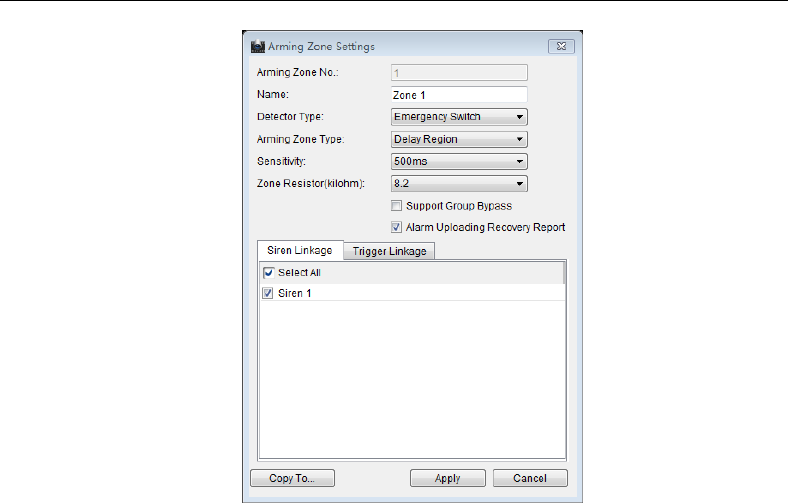
Control Panel User Manual
108
4. Edit the general information of the Zone, including name, probe type, arming Zone type,
sensitivity, entering delay, and existing delay and so on.
Probe Type: Select the type of the detector.
Arming Zone Type: Select the type of Zone in the partition
Sensitivity: Select the response time of the Zone.
5. Select the linked siren and linked relay.
6. Click Copy to to copy all these settings to other Zones.
7. Click Apply to save the settings.
Relay Configuration
Steps:
1. Enter the Zone configuration interface.
Remote Configuration-> Alarm-> Relay
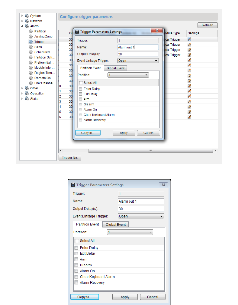
Control Panel User Manual
109
2. In the Alarm Output list, select an alarm input channel and double click the relay to
enter zone configuration page.
3. Edit the general information of the zone, including name, output delay and so on.
Output Delay (0~5999s): Configure the alarm output time after the alarm being
triggered.
4. Click the dropdown menu to enable/disable the event-linked relay.
5. Select the detailed operation after the alarm being triggered on the partition event
panel.
6. Select the global event of alarm triggering.
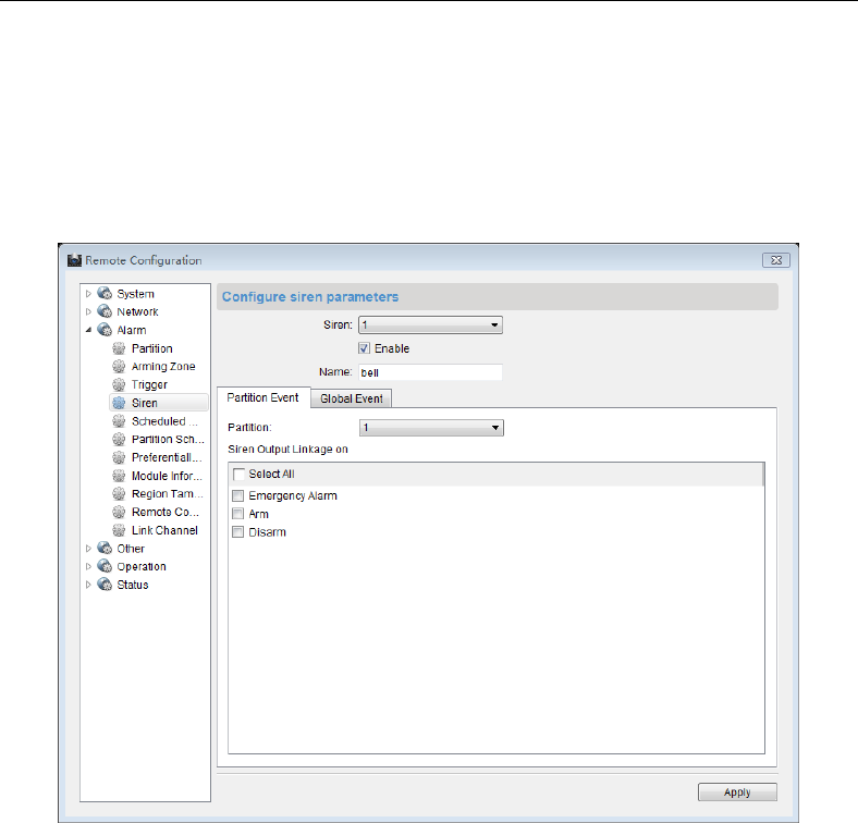
Control Panel User Manual
110
7. Click Copy to to copy all these settings to other Zones.
8. Click Apply to save the settings.
Siren Configuration
Steps:
1. Enter the siren configuration page.
Remote Configuration->Alarm->Siren
2. Click the Siren dropdown menu to select a siren needs to be configured.
3. Check the Enable box to enable the configuration.
4. Edit the siren name.
5. Select the detailed operation after the alarm being triggered on the partition event
panel.
6. Select the global event of alarm triggering.
7. Click Apply to save the settings.
Relay Output Schedule Configuration
Purpose:
You can set the schedule for turning on/off the relay in this section.
Steps:
1. Enter the relay output schedule configuration interface.
Remote Configuration->Alarm-> Output Schedule Rule
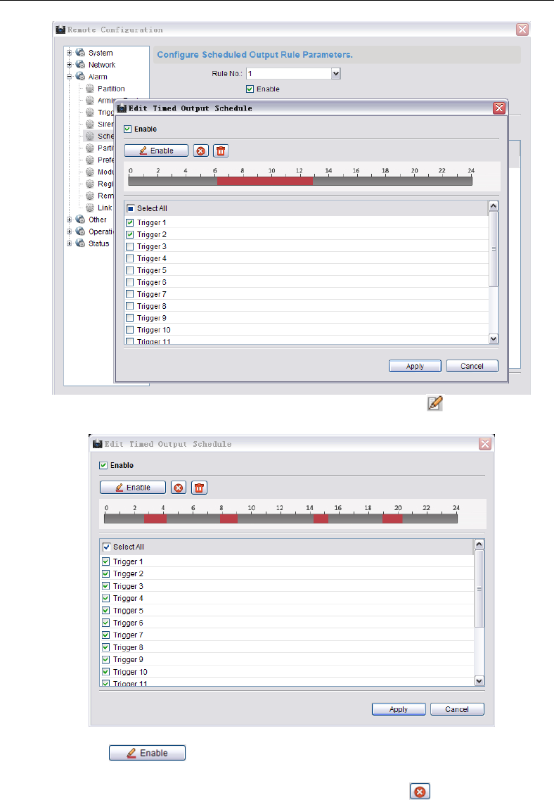
Control Panel User Manual
111
2. In the relay list, select an alarm input channel and click the icon to enter the Zone
configuration page.
3. Check the Enable checkbox to enable the configuration.
4. Click the icon , click and drag the mouse on the time bar (the time bar is
divided into 24 segments which represent 24 hours) to draw the required schedule.
Delete Schedule: click the drawn color bar and click the icon to delete the color
bar.
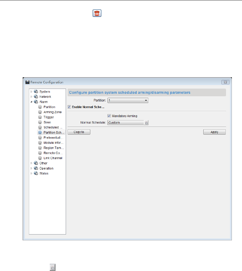
Control Panel User Manual
112
Clear Schedule: Click the icon to clear the drawn the schedule.
5. Check the Relay checkbox to select the relay.
6. Click Apply to save the settings.
Partition Arming/Disarming Schedule Configuration
Steps:
1. Enter the arming/disarming schedule configuration interface.
Remote Configuration->Alarm ->Partition Scheduling Arming/Disarming
2. Select a partition needs to be configured.
3. Check the Enable Normal Schedule checkbox to enable daily schedule for the partition.
You can select to enable the mandatory arming function.
4. Click the icon of the Template box to enter the schedule configuration interface.
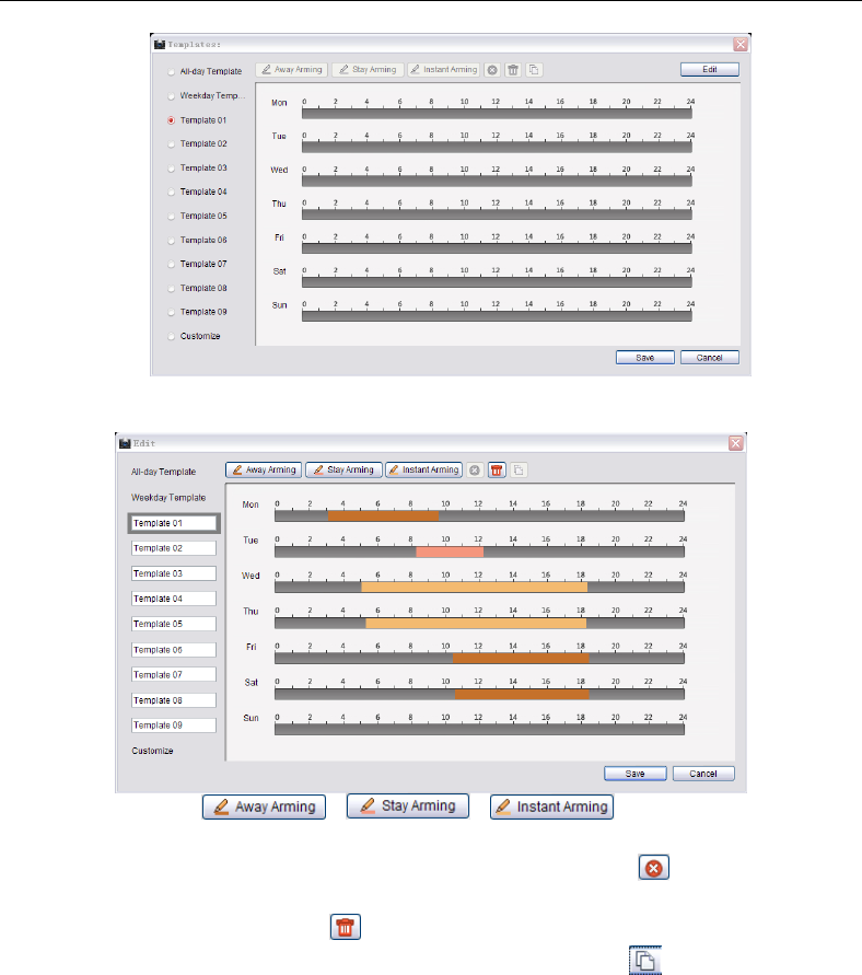
Control Panel User Manual
113
5. Click Edit to enable the schedule configuration.
6. Click and select a template.
7. Click the button / / to select an arming type.
8. Click and drag the mouse on the time bar to draw the daily schedule.
Delete Schedule: Click the drawn color bar and click the icon to delete the color
bar.
Clear Schedule: Click the icon to clear the drawn the schedule.
Copy Schedule: Click the drawn color bar and click the icon to copy this arming
schedule to other day of the week.
9. Click Save to save the settings and click Cancel to exit the page.
10. Click Copy to to copy all these settings to other Zones.
11. Click Apply to save the settings.
Arming/Disarming Preferential Schedule Configuration
Steps:
1. Enter the arming/disarming preferential schedule configuration interface.
Remote Configuration->Alarm->Preferential Schedule Arming/Disarming
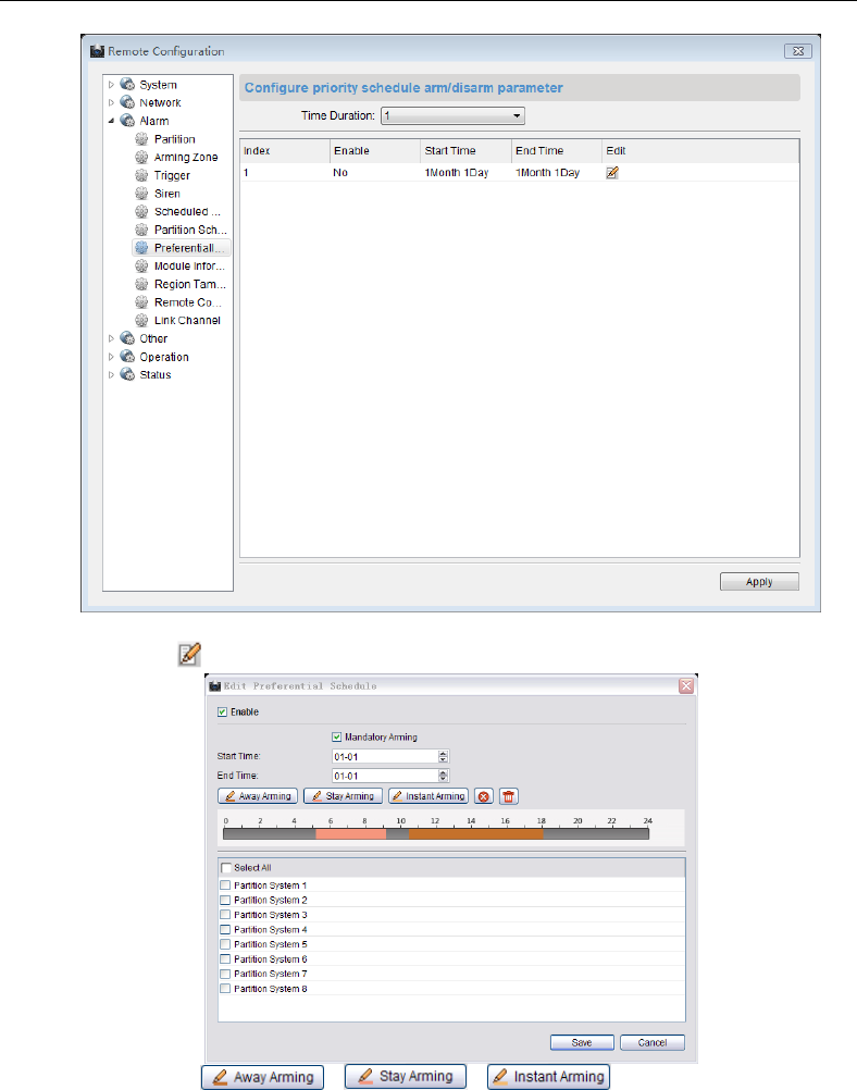
Control Panel User Manual
114
2. Click the drop down menu to select the time duration.
3. Click the icon to enter the preferential schedule configuration page.
4. Click the button / / to select an arming type.
5. Click and drag the mouse on the time bar to draw the daily schedule.
6. Click Save to save the settings and click Cancel to exit the page.
7. Click Copy to to copy all these settings to other Zones.
8. Click Apply to save the settings.
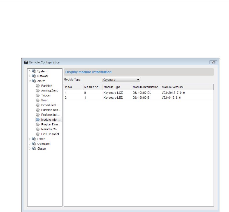
Control Panel User Manual
115
Module Information
Purpose:
You can view the information of external keypad and relay in this section.
Steps:
1. Enter the module information interface.
Remote Configuration->Alarm->Module Information
2. Click and select the external device from the module type dropdown menu.
3. View the information about the selected device.
Zone Tampering-proof Configuration
Steps:
1. Enter the Zone tampering configuration interface.
Remote Configuration->Alarm->Region Tampering Proof
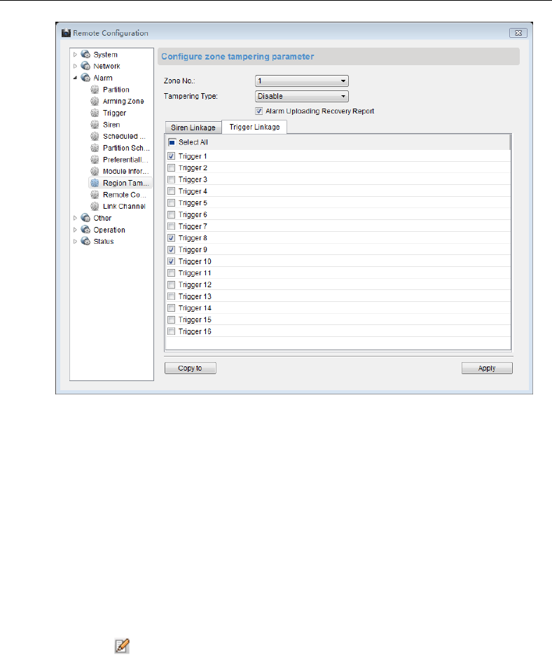
Control Panel User Manual
116
2. Click dropdown menu to select a Zone needs to be configured.
3. Select a tampering type.
4. Check the Upload Alarm Recovery Report checkbox to enable the function of
uploading alarm recovery report.
5. Select the linked siren on the Linked Siren panel.
6. Select the linked relay on the Linked Relay panel.
7. Click Copy to to copy all these settings to other Zones.
8. Click Apply to save the settings.
Remote Control Permission Configuration
Steps:
1. Enter the key fobs permission configuration interface.
Remote Configuration->Alarm->Remote Control Permission
2. Click the icon to enter the key fobs permission configuration page.
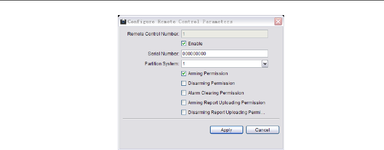
Control Panel User Manual
117
3. Check the Enable checkbox to enable the configuration
4. Enter the serial number of the key fobs.
5. Select the partition No. needs to be controlled.
6. Check the checkbox and select the permission for the key fobs.
7. Click Apply to save the settings.
4.6 Others
4.6.1 Fault Handling
In this section , you can select the fault detection type, alarm linked keypad and output
mode.
Steps:
1. Enter the fault handling interface.
Remote Configuration->Others->Fault Handling
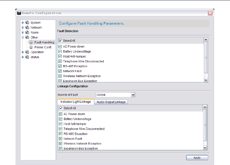
Control Panel User Manual
118
2. Select the fault detection type.
3. Click the Source of Fault dropdown menu to select the linked keypad.
4. Select the alarm output mode and corresponded fault detection type. The alarm
output mode can be selected as Linked Indicative Light and Linked Keypad Sound.
5. Click Apply to save the settings.
4.6.2 Printer Configuration
In this section , you can select to enable/disable the printer and the printing content.
Steps:
1. Enter the printer configuration interface.
Remote Configuration->Others->Printer Configuration
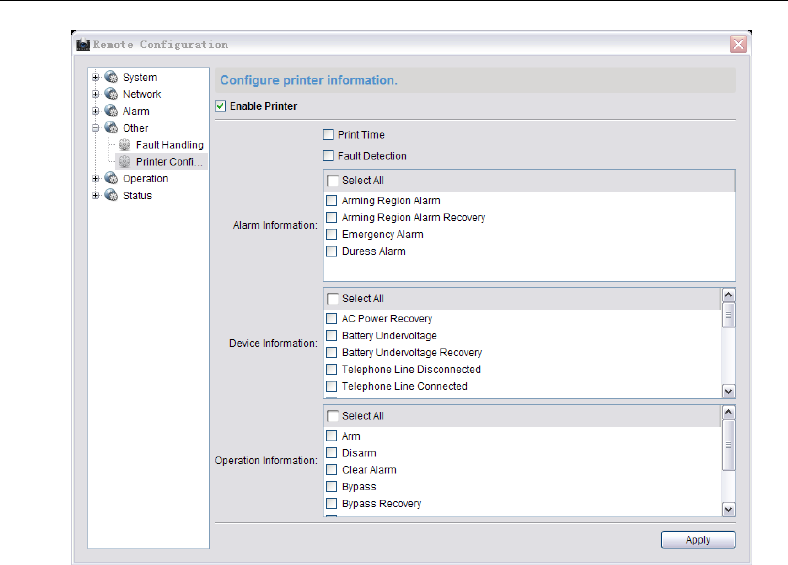
Control Panel User Manual
119
2. Check the checkbox to enable the printer.
3. Select the content to be printed, including time, fault, alarm information, device
information, and operation information.
4. Click Apply to save the settings.
4.7 Operation
You can configure the partition, zone, relay, siren, and fault warning audio in this section.
Click Remote Configuration->Operation to enter the interface.
Partition: you can arm/disarm the partition, clear alarm, bypass, and recover bypass of the
system.
Zone: you can bypass or recover bypass of the selected zone.
Tigger: you can select to turn on/off the selected relay.
Siren: you can enable/disable the specified siren.
Fault Warning Audio: you can select the faulted keypad and select to disable the warning
audio.
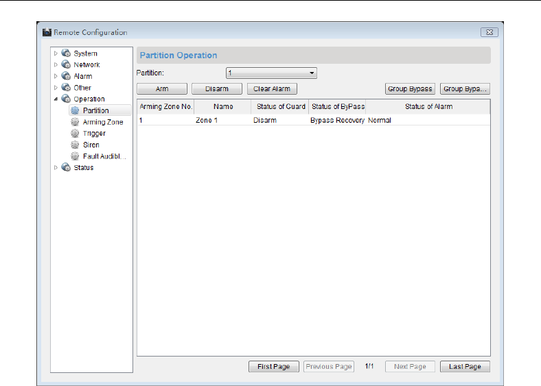
Control Panel User Manual
120
4.8 Status
You can view status of the partition, zone, relay, siren ,and storage battery in this section.
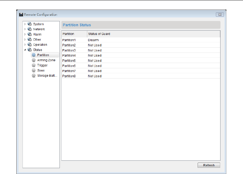
Control Panel User Manual
121

Control Panel User Manual
122
Chapter 5 Trouble Shooting
Q: What is the function of Project button of LCD keypad?
A: Project button has button switch function besides normal instruction button, such
as:
When sensor or module is abnormal, press and hold the Project button to switch to
other interfaces manually. When the sensor/module is abnormal or the keypad, press
the Project button once and the current display interface will be paused for 20s; press it
again to switch to the next LCD screen interface.
Q: How to manually switch to other abnormal interfaces when the LCD keypad displays
sensor/module is abnormal?
A:
1. Among the LCD keypad abnormal display interfaces, display interface of the sensor
alarm, module abnormal display interface are of first priority; the sensor abnormal
interface is of second priority, sensor bypass interface is of third priority.
2. If interfaces of different priority exist at same time, the system automatically displays
the interface of first priority.
3. The switch between interfaces of same priority: there are two ways to switch display
interface of the sensor alarm to sensor off-line display interface.
1) System auto-switch: The system will refresh automatically. If the current
display interface is accomplished and other interfaces of same priority exist,
system will auto switch to other interfaces.
2) Manually switch: Press the Project button continuously until it switches to
the interface to display.
4. Switch between interfaces of different priority: from sensor alarm interface to sensor
bypass interface:
Press and hold the Project button for multiple times until it switches to the interface to
display.
Q: What is the meaning of LCD keypad Arm/Disarm, Operate indicators?
A: LCD system keypad indicator:
1. The meaning of Arm/Disarm indicator (Red and Green) is shown below:
Working Status
Indicator Status
Working Status
Indicator Status
Enter programming
Green, Blink
Parameters
Initialization
Green, Blink
System Arming
Red, Normally On
System Disarming
Green, Normally On
2. The meaning of Operate indicator (Green) is shown below:

Control Panel User Manual
123
Working Status
Indicator Status
Working Status
Indicator Status
Enter programming
Green, Blink
Parameters
Initialization
Green, Blink
System Abnormal
Green, Blink
System Normal
Green, Normally On
Q: What are the steps of LED keypad to program the control panel?
A:
1. In overall keypad programming mode, the program command is: {installer password} +
{*} + {0} + {#};
2. To view the configuring operation for alarm control panel, please refer to alarm keypad
configuring code;
For example: program user password 2#, the password has arm/disarm function, does
not send arming report, does not allow bypass, password is 5678, and the program
code is shown as follow:
Command Code Arming Type Password End
{0}{0}{2} {3} {5}{6}{7}{8} {#}
3. Set program command
There are 2 alert sound of correct or 5 alert sound of error and corresponding OSD
notices after each program command is over. When 5 alert sound of error is heard and
the screen displays Operation Failed, there is error in program command setting and
the user need to reset correct program command. When 2 alert sound of correct is
heard and the screen displays Operation Succeeded but the setting parameters are
not the parameters needed, you can operate according to program command once
again.
4. Exit program mode, the program command is: {*} + {#}.
Q: What is the meaning of LED keypad Arm/Disarm, Operate, Camera indicators?
A:
LED alarm keypad Arm/Disarm indicator:
Working Status
Indicator Status
Working Status
Indicator Status
Armed
Red, Normally On
Enter Programming
Green, Blink
Disarmed
Green, Normally On
Main Operator
Change Password
Green, Blink
LED alarm keypad Operate indicator:
Working Status
Indicator Status
Working Status
Indicator Status
Normal
Green, Normally On
Keypad Not Logged In
Red, Blink
System Error
Orange, Blink
Enter Programming
Green, Blink
Project
Red, Normally On
Change Password
Green. Blink

Control Panel User Manual
124
LED alarm keypad Camera indicator:
Working Status
Indicator Status
Working Status
Indicator Status
Sensor Normal
Off
Sensor Error
Red, Normally On
Sensor Alarm
Red, Blink
Sensor Bypass
Green, Normally On
LED keypad Camera indicator under Project Mode:
No.
Description
No.
Description
1
Off-hook
5
Send CID Report
2
Dial
6
Receive Alert Sound
3
Alarm Connecter Disconnection
7
Control Panel Off-hook
4
Receive the Hand-shack Sound
8
Alarm Connector On-hook
LED keypad Camera indicator under Status Mode:
No.
Description
No.
Description
1
AC Power off
5
Keypad Off-line
2
Battery Low Voltage
6
Network Cable Off-line
3
Control Panel Tamper-proof On
7
No SIM Card
4
ADSL Cable Off-line
8
Reserved
Q: What is the meaning of LED keypad alert sound?
A: The meaning of LED keypad alert sound is as follows:
No.
Keypad Alert Sound
Description
1
1 Sound
Keypad Prompt, Error Operating Prompt
2
2 Sound
Correctly answered, report uploading
succeeded
3
5 Sound
Incorrectly answered, report uploading failed
in 60s
4
Last for 2s
Error Prompt
5
Intermittent Slow Sound,
Continuously
Enter/Exit Delay
6
Intermittent Rapid Sound,
Continuously
Enter/Exit Delay, 10s Left
7
Rapid Beep
Sensor Alarm, Keypad not logged in
Control Panel User Manual
125
No.
Keypad Alert Sound
Description
8
3 Long 2 Short
Keypad Tamper-proof On
Q: How to remove alarm memory?
A: There are two situations of removing alarm memory as shown below:
1) Under disarming mode: Press {*} + {1} + {#} or {Password} + {*} + {1} + {#}.
2) Under arming mode: Press {Password} + {*} + {1} + {#}.
Q: How to input hexadecimal number?
A: Input hexadecimal number with {*} button and number button {0} ~ {5}.
Q: How to set LED keypad address?
A: Set LED keypad address with the DIP address of keypad.
Conversion Table
Hexadecimal Number Corresponding Key
A
C
B
D
E
F
*0
*2
*1
*3
*4
*5
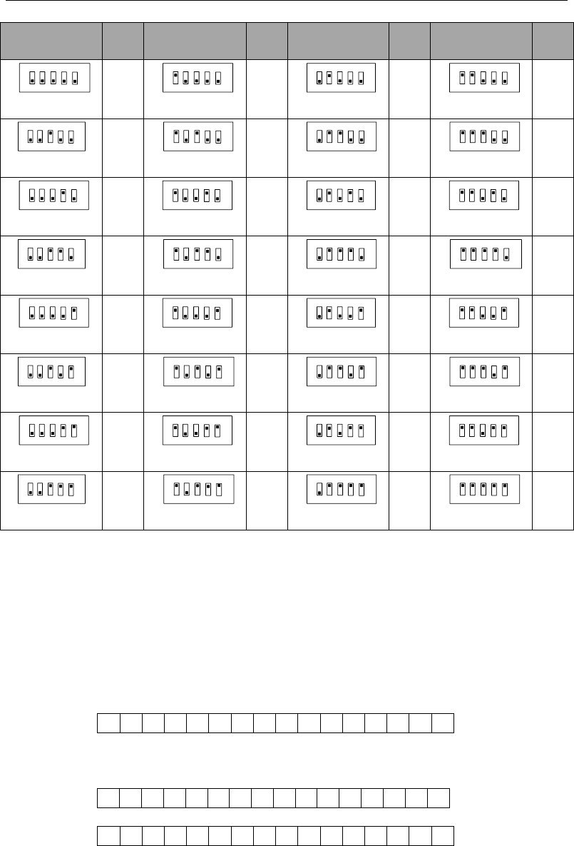
Control Panel User Manual
126
DIP
Add
.
DIP
Add
.
DIP
Add
.
DIP
Add
.
21 3 4 5
ON DIP
0
21 3 4 5
ON DIP
1
21 3 4 5
ON DIP
2
21 3 4 5
ON DIP
3
21 3 4 5
DIP
ON
4
21 3 4 5
DIP
ON
5
21 3 4 5
DIP
ON
6
21 3 4 5
DIP
ON
7
21 3 4 5
ON DIP
8
21 3 4 5
ON DIP
9
21 3 4 5
ON DIP
10
21 3 4 5
ON DIP
11
21 3 4 5
DIP
ON
12
21 3 4 5
DIP
ON
13
21 3 4 5
DIP
ON
14
21 3 4 5
DIP
ON
15
21 3 4 5
ON DIP
16
21 3 4 5
ON DIP
17
21 3 4 5
ON DIP
18
21 3 4 5
ON DIP
19
21 3 4 5
DIP
ON
20
21 3 4 5
DIP
ON
21
21 3 4 5
DIP
ON
22
21 3 4 5
DIP
ON
23
21 3 4 5
ON DIP
24
21 3 4 5
ON DIP
25
21 3 4 5
ON DIP
26
21 3 4 5
ON DIP
27
21 3 4 5
DIP
ON
28
21 3 4 5
DIP
ON
29
21 3 4 5
DIP
ON
30
21 3 4 5
DIP
ON
31
Q: Why is it needed to input E at the end of keypad configured phone number?
A: Control panel can process phone number with 31 characters. Input number with 16
characters in each command address so that 2 addresses are needed for storage phone
number. However, the phone numbers are different in every place so the control panel
needs a special data bit to check if the phone number is complete. Character E ({*} {4})
is for checking if the phone number is complete.
For example: The first Alarm connecter phone number is 0571-88075998, user can input
the following command:
Command Address 460
0
5
7
1
8
8
0
7
5
9
9
8
E
For example: The first alarm connecter phone number is 17951-88075998, user can input
the following command:
Command Address 460
1
7
9
5
1
F
F
F
8
8
0
7
5
9
9
8
Command Address 461
E

Control Panel User Manual
127
For example: The first alarm connecter phone number is 0571-88075998-8888, user can
input the following command:
Command Address 460
0
5
7
1
8
8
0
7
5
9
9
8
F
F
F
8
Command Address 461
8
8
8
E
Q: What are notes for setting password?
A: The password for each operator should be different; otherwise the setting will be failed.
For example, if the password of operator 1 is set to be 1234 hen password of operator 2
is also 1234, it will prompt to be error. In addition, the password of each operator
should be different from the control panel duress code of other operators; otherwise
the setting will be failed. For example if the password of operator No.3 is 3456 and the
password of operator No.4 is set to be3455 or 3457, it will prompt to be error.
Q: What are notes for setting duress code?
A:
1. The description of duress code is as follow:
Input duress code when the user is under duress, it will work as if the user inputs valid
password, but the system will auto-upload the alarm information. For example when a
criminal forces the user to disarm the alarm, user can input the control panel duress
code to disarm the system and upload the alarm information to the center
automatically and off the criminal’s guard.
2. Please note when setting duress code: duress code is the valid password with its last
number±1.
For example: Valid Password: 1234, Duress Code: 1235 and 1233.
For example: Valid Password: 1230, Duress Code: 1231 and 1239.
For example: Valid Password: 1239, Duress Code: 1230 and 1238.
3. Please take the following notes while using duress code:
While using duress code, it is needed to enable duress report firstly, as to program the
control panel duress report and delay. The programming command to enable Control
Panel Duress Report is as follow:
Command Address {4}{6}{4}
Enter Delay {3}
Exit Delay {6}
Siren Working Duration {2}
Control Panel Duress Report {1}
End {#}
Q: How to solve the problem of two LED keypad address being same?
A: When two LED keypad addresses are the same, the situation of two keypads demanding
bus communication at the same time will appear and cause conflict. The only solution is
to remove one keypad and reset the other keypad to an unused legal address. Restore
the control panel by processing program code ({Main Operator}{*}{6}{8}{#})

Control Panel User Manual
128
Q: Why there is no Disarming Report?
A: To make sure the user has permission of Disarming Report, please refer to Operator
Configuration.
Q: What to do if the user cannot disarm after arming the system?
A: There are two different situations:
1. The user does not have permission to disarm, please contact the administrator.
2. Take the follow instructions when there is only one user in the system without
permission to disarm;
1) Initialize the hardware, restore the password of operator, main operator password
and permission, and then disarm with main operator. The initialization password of
operator is: 012345, the initialization password of main operator is: 1234, the
permission is: arm/disarm. There is arm/disarm report and bypass is permitted.
Please refer to FAQ of hardware initialization for more information about hardware
initialization.
2) The command code to restore factory parameters: {Password of operator} + {*} + {8}
+ {9} + {#}.
This method is not recommended because it will initialize all programming
contents.
Q: How to do the hardware initialization?
A: Control panel hardware initialization only initializes operator password: 012345 and main
operator password: 1234, main operator permission is arm/disarm. There are
arming/disarming report and allows bypass.
Steps:
1) Power off the control panel and open the cover;
2) Short the restore switch of the control panel with shorting nut or connection
cables;
3) Power on the control panel and power off it 10s later;
4) Please remove the shorting nut or connection cable on the restore switch;
5) Cover the control panel well;
6) Recharge the control panel;
Q: Why is there no response for keypad operational order but alert sound of error 10s
later?
A: It may be caused by follow situations:
1) Poor contact of the connection cable between LED keypad and the control panel,
please check if the cable is normal;
2) The LED keypad is considered as off-line in the communication. If there is other
keypad operates normal, process program command {Main Operator Password} +
{*} + {6} + {8} + {#}to restore it or power off the control panel and reboot.
Q: How does the control panel detect alternating current, storage battery, control panel
tamper-proof and ADSL cable?
A: The status of the control panel detection is as follows:

Control Panel User Manual
129
1) The control panel detects AC power supply status once in a while;
2) The control panel detects storage battery status once in a while;
3) The control panel detects tamper-proof status once in a while;
4) The control panel detects ADSL cable status once in a while.
Q: The network is disconnected.
A:
1) Please check if the network status indicator of the board is normal on;
2) If the network status indicator is not normal on, please check if the network cable
connection is normal.
Q: What if the client cannot log in the device?
A: Troubleshoot according to the prompt.
Please check if the device IP Address and Port No. are correct. The device default IP
Address is: 192.0.0.64, and the Port No. is: 8000.
Please check if the user name and password to log in the control panel are correct. The
default user name is: admin, the word is: 12345.
Q: Why the control panel cannot communicate with the alarm center group?
A: The configuration of control panel communicating with the alarm center group is as
follows:
1) If the user communicates with the center via LAN: Configure parameters such as
monitoring IP, Port No., User Account and Communication Protocols of the remote
alarm center in Remote Configuration-> Others-> Network Center Configuration;
2) If the user communicates via dialing: Configure parameters such as phone number,
receiver identity account and communication protocols of the remote alarm center
in Remote Configuration-> Others-> Dialing Parameter Setting;
3) If the user communicates via WIFI: Configure APN Name and Parameters of remote
alarm center in Remote Configuration-> Others-> WIFI Parameter Setting. The
parameters include monitoring IP, Port No., User Account and Communication
Protocol, etc.;
4) After setting dialing parameters, LAN parameters and WIFI parameters, configure
the uploading mode in Remote Configuration-> Uploading Mode Configuration
Q: How to configure the communication way of control panel and alarm center group?
A:
1. Center uploading mode supports at most 6 center groups, each center group divides in
main channel and 3 backup channels;
2. If the center group is enabled. Enable the center group before the use.
3. For example: The control panel needs to upload report to network alarm center 1 and
dialing alarm center1 and network alarm center 1 needs to upload report to network
alarm center 2 when it fails to upload it. The configurations are as follows:
1) Enable Group1 and Group2;
2) In the uploading mode configuration list, select N1 in center group 1 main channel,

Control Panel User Manual
130
select N2 in backup channel 1, select T1 in Center group2 main channel.
3) Click Apply.
If the client is not opened, the user can realize communication with alarm center by
programming with keypad. For detailed operations please refer to program command
611~634.
Q: Why cannot it upload report and control after WIFI is enabled?
A: The follow situations may lead to WIWI connection failure:
1) No SIM Card or poor contact;
2) 3G module antenna is not normally connected or with poor signal;
3) WIFI parameter setting is incorrect;
4) SIM Card has no enough tariffs.

Control Panel User Manual
131
Appendix1:Specifications
Model
DS-19A08/16-BN
DS-19A08/16-BNG
Security
Control
Panel
Parameters
Alarm Input
8/16 Zones Input
Alarm Output
Local 4-ch + 12-ch expandable, 1A/30VDC
Siren Power Supply
12VDC /750mA
PSTN
Support
Supported External
Keypads (LCD/LED)
32
Tamper-proof Switch
1, Support tamper-proof function
Weekly Schedule
8 time segments each day
Holiday Schedule
30 days, 8 time segments each day
Partitions
8 partitions, one can be set as public partition
Detector Tamper-proof
Alarm
Support
SMS Alarm-Report Push
N/A
Support
Arming/Disarming via
SMS Command
N/A
Support
Key Fobs
32 (Unobstructed Effective Range of 100m)
Wireless Network
Standard
N/A
GPRS
UIM Card Slot
1
SMA Antenna Interface
1
Network
Management
Network Application
DNS, IPServer, DDNS, and DHCP
External
Interface
Network Interface
1 RJ45 10M/100M Self-adaptive
Keypad Bus
1, RS485 Half-duplex
Port for Storage Battery
1 Port, for Storage Battery Accessing 12VDC, 7Ah
Printer Interface
1 RS-232 Info. Output Interface
Others
Power Supply
AC220V/AC110V
Consumption
≤5W(Load Power≤40W)
Working Temperature
-10°C~+55°C
Working Humidity
10%~90%
Installation Mode
Wall-mounting
Dimensions
370×320×86mm
Weight
< 3.5kg

Control Panel User Manual
132
Appendix2:CID Report
CID Code
Description
CID Code
Description
1103
Real-time Zone Alarm
3103
Real-time Zone Alarm
Recovery
1110
Fire Zone Alarm
3110
Fire Zone Alarm Recovery
1122
24-hour Non-voiced
Zone Alarm
3122
24-hour Non-voiced Zone
Alarm Recovery
1123
24-hour Voiced Zone
Alarm
3123
24-hour Voiced Zone Alarm
Recovery
1131
Perimeter Zone Alarm
3131
Perimeter Zone Alarm
Recovery
1132
Internal Delay Zone
Alarm
3132
Internal Delay Zone Alarm
Recovery
1134
Delay Zone Alarm
3134
Delay Zone Alarm Recovery
1137
Tampering Alarm
3137
Tampering Alarm Recovery
1301
AC Power Down
3301
AC Power Down Recovery
1302
Low Battery
3302
Low Battery Recovery
1305
Control Panel Restoring
1121
Control Panel Duress Alarm
1336
Printer Disconnection
3336
Printer Disconnection
Recovery
1354
Phone Line
Disconnection
3354
Phone Line Disconnection
Recovery
1382
Local Expanded Zone
Fault
3382
Local Expanded Zone Recovery
1401
Disarming
3401
Arming
1406
Alarm Clearing Memory
Canceling
1810
Soft Zone Emergency Alarm
1570
Zone Bypass
3570
Zone Bypass Recovery
1574
Group Bypass
3574
Group Bypass Recovery
1601
Manual Testing Report
1602
Regular Testing Report
1627
Programming Entering
1628
Programming Exiting

Control Panel User Manual
133
CID Code
Description
CID Code
Description
1910
Keypad Disconnection
3910
Keypad Disconnection
Recovery
1911
Keypad Bus Relay
Disconnection
3911
Keypad Bus Relay
Disconnection Recovery
1921
Wireless Network
Exception
3921
Wireless Network Recovery
1931
Wired Network
Exception
3931
Wired Network Recovery
1930
IP Address Conflict
3930
IP Address Recovery
1931
Network Cable
Disconnection
3931
Network Cable Recovery
1940
Motion Detection
Enabling
3940
Motion Detection Disabling
1941
Tampering Alarm
Enabling
3941
Tampering Alarm Disabling
1942
Video Loss Alarm
Enabling
3942
Video Loss Alarm Disabling
1943
Unmatched Input/
Output Format
3943
Input/ Output Format
Recovery
1944
Video Input Exception
3944
Video Input Recovery
1945
HDD Full Alarm
3945
HDD Recovery (For HDD Full)
1946
HDD Fault Alarm
3946
HDD Recovery (For HDD Fault)
3408
Real-time Arming
3441
Stay Arming

Control Panel User Manual
134
Appendix3:LED Keypad Prompt Sound
No.
Keypad Prompt Sound
Description
1
1 Sound
Keypad Prompt, Error Operating Prompt
2
2 Sound
Correctly answered, report uploading
succeeded
3
5 Sound
Incorrectly answered, report uploading failed
in 60s
4
Last for 2s
Error Prompt
5
Intermittent Slow Sound,
Continuously
Enter/Exit Delay
6
Intermittent Rapid
Sound, Continuously
Enter/Exit Delay, 10s Left
7
Rapid Beep
Sensor Alarm, Keypad not logged in
8
3 Long 2 Short
Keypad Tamper-proof On
Appendix4:Conversion Table
Conversion Table
Hexadecimal Number Corresponding Key
A
C
B
D
E
F
*0
*2
*1
*3
*4
*5

Control Panel User Manual
135
Control Panel Command Table
0 0 #0
0 1 *2 1 2 3 4 #1#Password
0User Name: 0 2 6 0 0 0 0 #2#Password
0User Name:
0 3 6 0 0 0 0 #3#Password
0User Name:0 4 6 0 0 0 0 #4#Password
0User Name:
0 5 6 0 0 0 0 #5#Password
0User Name:0 6 6 0 0 0 0 #6#PasswordPa
ssword
0User Name:
0 7 6 0 0 0 0 #7#Password
0User Name:0 8 6 0 0 0 0 #8#Password
0User Name:
0 9 6 0 0 0 0 #9#Password
0User Name:1 0 6 0 0 0 0 #10#Password
0User Name:
1 1 6 0 0 0 0 #11#Password
0User Name:1 2 6 0 0 0 0 #12#Password
0User Name:
1 3 6 0 0 0 0 #13#Password
0User Name:1 4 6 0 0 0 0 #14#Password
0User Name:
1 5 6 0 0 0 0 #15#Password
01 6 6 0 0 0 0 #16#PasswordP
assword
0User Name:
User Name:
1 2 3 4 5
1 7 6 0 0 0 0 #17#Password
0User Name:1 8 6 0 0 0 0 #18#Password
0User Name:
1 9 6 0 0 0 0 #19#Password
0User Name:2 0 6 0 0 0 0 #20#Password
0User Name:
2 1 6 0 0 0 0 #21#Password
0User Name:2 2 6 0 0 0 0 #22#Password
0User Name:
2 3 6 0 0 0 0 #23#Password
0User Name:2 4 6 0 0 0 0 #24#Password
0User Name:
2 5 6 0 0 0 0 #25#Password
0User Name:2 6 6 0 0 0 0 #26#Password
0User Name:
2 7 6 0 0 0 0 #27#Password
0User Name:2 8 6 0 0 0 0 #28#Password
0User Name:
2 9 6 0 0 0 0 #29#Password
0User Name:3 0 6 0 0 0 0 #30#Password
0User Name:
3 1 6 0 0 0 0 #31#Password
03 2 6 0 0 0 0 #32#Password
0User Name:
User Name:
3 5 6 0 0 0 0 #35#Password
0User Name:3 6 6 0 0 0 0 #36#Password
0User Name:
3 7 6 0 0 0 0 #37#Password
0User Name:3 8 6 0 0 0 0 #38#Password
0User Name:
3 9 6 0 0 0 0 #39#Password
0User Name:4 0 6 0 0 0 0 #40#Password
0User Name:
4 1 6 0 0 0 0 #41#Password
0User Name:4 2 6 0 0 0 0 #42#Password
0User Name:
4 3 6 0 0 0 0 #43#Password
0User Name:4 4 6 0 0 0 0 #44#Password
0User Name:
4 5 6 0 0 0 0 #45#Password
0User Name:4 6 6 0 0 0 0 #46#Password
0User Name:
4 7 6 0 0 0 0 #47#Password
0User Name:4 8 6 0 0 0 0 #48#Password
0User Name:
4 9 6 0 0 0 0 #49#Password
05 0 6 0 0 0 0 #50#Password
0User Name:
User Name:
3 3 6 0 0 0 0 #33#Password
03 4 6 0 0 0 0 #34#Password
0User Name:
User Name:
0Installer
Password

Control Panel User Manual
136
5 1 6 0 0 0 0 #51#Password
0User Name:5 2 6 0 0 0 0 #52#Password
0User Name:
5 3 6 0 0 0 0 #53#Password
0User Name:5 4 6 0 0 0 0 #54#Password
0User Name:
5 5 6 0 0 0 0 #55#Password
0User Name:5 6 6 0 0 0 0 #56#Password
0User Name:
5 7 6 0 0 0 0 #57#Password
0User Name:5 8 6 0 0 0 0 #58#Password
0User Name:
5 9 6 0 0 0 0 #59#Password
0User Name:6 0 6 0 0 0 0 #60#Password
0User Name:
6 1 6 0 0 0 0 #61#Password
0User Name:6 2 6 0 0 0 0 #62#Password
0User Name:
6 3 6 0 0 0 0 #63#Password
0User Name:6 4 6 0 0 0 0 #64#Password
0User Name:
6 5 6 0 0 0 0 #65#Password
06 6 6 0 0 0 0 #66#Password
0User Name:
User Name:
6 7 6 0 0 0 0 #67#Password
0User Name:6 8 6 0 0 0 0 #68#Password
0User Name:
6 9 6 0 0 0 0 #69#Password
0User Name:7 0 6 0 0 0 0 #70#Password
0User Name:
7 1 6 0 0 0 0 #71#Password
0User Name:7 2 6 0 0 0 0 #72#Password
0User Name:
7 3 6 0 0 0 0 #73#Password
0User Name:7 4 6 0 0 0 0 #74#Password
0User Name:
7 5 6 0 0 0 0 #75#Password
0User Name:7 6 6 0 0 0 0 #76#Password
0User Name:
7 7 6 0 0 0 0 #77#Password
0User Name:7 8 6 0 0 0 0 #78#Password
0User Name:
7 9 6 0 0 0 0 #79#Password
0User Name:8 0 6 0 0 0 0 #80#Password
0User Name:
8 1 6 0 0 0 0 #81#Password
08 2 6 0 0 0 0 #82#Password
0User Name:
User Name:
8 5 6 0 0 0 0 #85#Password
0User Name:8 6 6 0 0 0 0 #86#Password
0User Name:
8 7 6 0 0 0 0 #87#Password
0User Name:8 8 6 0 0 0 0 #88#Password
0User Name:
8 9 6 0 0 0 0 #89#Password
0User Name:9 0 6 0 0 0 0 #90#Password
0User Name:
9 1 6 0 0 0 0 #91#Password
0User Name:9 2 6 0 0 0 0 #92#Password
0User Name:
9 3 6 0 0 0 0 #93#Password
0User Name:9 4 6 0 0 0 0 #94#Password
0User Name:
9 5 6 0 0 0 0 #95#Password
0User Name:9 6 6 0 0 0 0 #96#Password
0User Name:
9 7 6 0 0 0 0 #97#Password
0User Name:9 8 6 0 0 0 0 #98#Password
0User Name:
9 9 6 0 0 0 0 #99#Password
00 0 6 0 0 0 0 #100#Password
1User Name:
User Name:
8 3 6 0 0 0 0 #83#Password
08 4 6 0 0 0 0 #84#Password
0User Name:
User Name:

Control Panel User Manual
137
0 1 6 0 0 0 0 #101#Password
1User Name:0 2 6 0 0 0 0 #102#Password
1User Name:
0 3 6 0 0 0 0 #103#Password
1User Name:0 4 6 0 0 0 0 #104#Password
1User Name:
0 5 6 0 0 0 0 #105#Password
1User Name:0 6 6 0 0 0 0 #106#Password
1User Name:
0 7 6 0 0 0 0 #107#Password
1User Name:0 8 6 0 0 0 0 #108#Password
1User Name:
0 9 6 0 0 0 0 #109#Password
1User Name:1 0 6 0 0 0 0 #110#Password
1User Name:
1 1 6 0 0 0 0 #111#Password
1User Name:1 2 6 0 0 0 0 #112#Password
1User Name:
1 3 6 0 0 0 0 #113#Password
1User Name:1 4 6 0 0 0 0 #114#Password
1User Name:
1 5 6 0 0 0 0 #115#Password
11 6 6 0 0 0 0 #116#Password
1User Name:
User Name:
1 7 6 0 0 0 0 #117#Password
1User Name:1 8 6 0 0 0 0 #118#Password
1User Name:
1 9 6 0 0 0 0 #119#Password
1User Name:2 0 6 0 0 0 0 #120#Password
1User Name:
2 1 6 0 0 0 0 #121#Password
1User Name:2 2 6 0 0 0 0 #122#Password
1User Name:
2 3 6 0 0 0 0 #123#Password
1User Name:2 4 6 0 0 0 0 #124#Password
1User Name:
2 5 6 0 0 0 0 #125#Password
1User Name:2 6 6 0 0 0 0 #126#Password
1User Name:
2 7 6 0 0 0 0 #127#Password
1User Name:2 8 6 0 0 0 0 #128#Password
1User Name:
2 9 6 0 0 0 0 #129#Password
1User Name:3 0 6 0 0 0 0 #130#Password
1User Name:
3 1 6 0 0 0 0 #131#Password
13 2 6 0 0 0 0 #132#Password
1User Name:
User Name:
3 5 6 0 0 0 0 #135#Password
1User Name:3 6 6 0 0 0 0 #136#Password
1User Name:
3 7 6 0 0 0 0 #137#Password
1User Name:3 8 6 0 0 0 0 #138#Password
1User Name:
3 9 6 0 0 0 0 #139#Password
1User Name:4 0 6 0 0 0 0 #140#Password
1User Name:
4 1 6 0 0 0 0 #141#Password
1User Name:4 2 6 0 0 0 0 #142#Password
1User Name:
4 3 6 0 0 0 0 #143#Password
1User Name:4 4 6 0 0 0 0 #144#Password
1User Name:
4 5 6 0 0 0 0 #145#Password
1User Name:4 6 6 0 0 0 0 #146#Password
1User Name:
4 7 6 0 0 0 0 #147#Password
1User Name:4 8 6 0 0 0 0 #148#Password
1User Name:
4 9 6 0 0 0 0 #149#Password
15 0 6 0 0 0 0 #150#Password
1User Name:
User Name:
3 3 6 0 0 0 0 #133#Password
13 4 6 0 0 0 0 #134#Password
1User Name:
User Name:

Control Panel User Manual
138
5 1 6 0 0 0 0 #151#Password
1User Name:5 2 6 0 0 0 0 #152#Password
1User Name:
5 3 6 0 0 0 0 #153#Password
1User Name:5 4 6 0 0 0 0 #154#Password
1User Name:
5 5 6 0 0 0 0 #155#Password
1User Name:5 6 6 0 0 0 0 #156#Password
1User Name:
5 7 6 0 0 0 0 #157#Password
1User Name:5 8 6 0 0 0 0 #158#Password
1User Name:
5 9 6 0 0 0 0 #159#Password
1User Name:6 0 6 0 0 0 0 #160#Password
1User Name:
6 1 6 0 0 0 0 #161#Password
1User Name:6 2 6 0 0 0 0 #162#Password
1User Name:
6 3 6 0 0 0 0 #163#Password
1User Name:6 4 6 0 0 0 0 #164#Password
1User Name:
6 5 6 0 0 0 0 #165#Password
16 6 6 0 0 0 0 #166#Password
1User Name:
User Name:
6 7 6 0 0 0 0 #167#Password
1User Name:6 8 6 0 0 0 0 #168#Password
1User Name:
6 9 6 0 0 0 0 #169#Password
1User Name:7 0 6 0 0 0 0 #170#Password
1User Name:
7 1 6 0 0 0 0 #171#Password
1User Name:7 2 6 0 0 0 0 #172#Password
1User Name:
7 3 6 0 0 0 0 #173#Password
1User Name:7 4 6 0 0 0 0 #174#Password
1User Name:
7 5 6 0 0 0 0 #175#Password
1User Name:7 6 6 0 0 0 0 #176#Password
1User Name:
7 7 6 0 0 0 0 #177#Password
1User Name:7 8 6 0 0 0 0 #178#Password
1User Name:
7 9 6 0 0 0 0 #179#Password
1User Name:8 0 6 0 0 0 0 #180#Password
1User Name:
8 1 6 0 0 0 0 #181#Password
18 2 6 0 0 0 0 #182#Password
1User Name:
User Name:
8 5 6 0 0 0 0 #185#Password
1User Name:8 6 6 0 0 0 0 #186#Password
1User Name:
8 7 6 0 0 0 0 #187#Password
1User Name:8 8 6 0 0 0 0 #188#Password
1User Name:
8 9 6 0 0 0 0 #189#Password
1User Name:9 0 6 0 0 0 0 #190#Password
1User Name:
9 1 6 0 0 0 0 #191#Password
1User Name:9 2 6 0 0 0 0 #192#Password
1User Name:
9 3 6 0 0 0 0 #193#Password
1User Name:9 4 6 0 0 0 0 #194#Password
1User Name:
9 5 6 0 0 0 0 #195#Password
1User Name:9 6 6 0 0 0 0 #196#Password
1User Name:
9 7 6 0 0 0 0 #197#Password
1User Name:9 8 6 0 0 0 0 #198#Password
1User Name:
9 9 6 0 0 0 0 #199#Password
10 0 6 0 0 0 0 #200#Password
2User Name:
User Name:
8 3 6 0 0 0 0 #183#Password
18 4 6 0 0 0 0 #184#Password
1User Name:
User Name:

Control Panel User Manual
139
0 1 2 5 0 1 #Region1
Parameters
Configuration
210 2 2 5 0 1 #Region2
Parameters
Configuration
21
0 3 2 5 1 0 #Region3
Parameters
Configuration
200 4 2 5 0 1 #Region4
Parameters
Configuration
21
0 5 2 5 0 1 #Region5
Parameters
Configuration
210 6 2 5 0 1 #Region6
Parameters
Configuration
21
0 7 2 5 0 1 #Region7
Parameters
Configuration
210 8 2 5 0 1 #Region8
Parameters
Configuration
21
0
1
0
0
0
0
0
0
0 9 2 5 0 1 #Region9
Parameters
Configuration
211 0 2 5 0 1 #Region10
Parameters
Configuration
21
1 1 2 5 1 0 #Region11
Parameters
Configuration
201 2 2 5 0 1 #Region12
Parameters
Configuration
21
1 3 2 5 0 1 #Region13
Parameters
Configuration
211 4 2 5 0 1 #Region14
Parameters
Configuration
21
1 5 2 5 0 1 #Region15
Parameters
Configuration
211 6 2 5 0 1 #Region16
Parameters
Configuration
21
0
1
0
0
0
0
0
0
5 7 0 0 3 3 #Communication
Control
4
5 8 0 0 0 0 #Alarm Center 1
Account
Settings
4 5 9 0 0 0 0 #Alarm Center 2
Account
Settings
4
6 0 E 0 0 0 #
4
6 1 0#
4
0 0 0 0 0 0 0 0 0 0 0 0
0 0 0 0 0 0 0 0 0 0 0 0 0 0 0
6 2 0#
4E 0 0 0 0 0 0 0 0 0 0 0 0 0 0
6 3 0#
40 0 0 0 0 0 0 0 0 0 0 0 0 0 0
Alarm Center 1Phone
Number Settings
Alarm Center 1Phone
Number Settings
Alarm Center 2Phone
Number Settings
Alarm Center 2Phone
Number Settings

Control Panel User Manual
140
6 7 Region Linked Trigger Configuration
4#
6 8 #Enable Trigger Event Linkage
Configuration
4
6 9 #
4
7 0 Trigger Time Settings
4#7 1 Siren Settings
4#
1
00 0 0 0 0
00 0 0 0 0
00 0 0 0 0
00 0 0 0 0
0
0Disable Trigger Event Linkage
Configuration
7 3 Host IP Address
Settings
4
7 4 #Host Port Number
Settings
4
7 24 0 1
10 0 0 6 4 #
08 0 0
0
1 0 0
8 0 00 #
0
2 0 3
1Host Time
Settings
9 2 0 0 0 0
7 6 Gateway Settings
4
7 54 5 5
00 0 0 0 0 #
5 5 0
0
2
2 5 2
5Subnet Mask
Settings
0 0 0 0 0 0
0#
8 54 00 0 0 0 0 #
0 0 0 0 0 0
8 64 0#
0 0 0 0
8 74 2#
0 0 0 0 0 0
Network Center 1 IP
Configuration Programming
Address
Network Center 1 Port
Configuration Programming
Address
Network Center 1 Protocol and
Account Configuration
Programming Address
8 84 00 0 0 0 0 #
0 0 0 0 0 0
8 94 0#
0 0 0 0
9 04 2#
0 0 0 0 0 0
Network Center 2 IP
Configuration Programming
Address
Network Center 2 Port
Configuration Programming
Address
Network Center 2 Protocol and
Account Configuration
Programming Address
9 14 00 0 0 0 0 #
0 0 0 0 0 0
9 24 0#
0 0 0 0
9 34 2#
0 0 0 0 0 0
Wireless Center 1 IP
Configuration Programming
Address
Wireless Center 1 Port
Configuration Programming
Address
Wireless Center 1 Protocol and
Account Configuration
Programming Address

Control Panel User Manual
141
9 44 00 0 0 0 0 #
0 0 0 0 0 0Wireless Center 2 IP
Configuration Programming
Address
9 54 0#
0 0 0 0
9 64 2#
0 0 0 0 0 0
Wireless Center 2 Port
Configuration Programming
Address
Wireless Center 2 Protocol and
Account Configuration
Programming Address
0 1 Device Information
Printing
Configuration
5
0 2 #Operation Programming
Information Printing
Configuration
5
0 0 0 0 0 #Alarm Information
Printing
Configuration
5
00 0 0 0 0 #
00 0 0
0 0 0
0 3 Alarm and Bypass Recovery
Printing Configuration
5#
0 0
9 9 0 0 0 #Printer
Configuration
4
0 0
0 4 #Device Recovery
Information Printing
Configuration
500 0 0
0 0 0
1 0 0 1 0 #System Emergency Alarm Linked Siren Configuration
5
1 1 Host Tamper-proof
Configuration
5#
0
1 3 0 1 5 #Testing Report
Configuration
5
3 1 System Time and Hostage
Report Configuration
551 3 2 0 #
3 1 System Report and
Arming/Disarming Prompt
Configuration
560 0 0 0 #
3 1 System Key User
Permission
Configuration
571 1 1 1 #
6 4 Host System Fault
Detection Configuration
511 1 1 1 #
6 7 #System Fault
Display
Configuration
501 1 1
1 1 1
1 1
1 1
6 8 #System Keyboard
Fault Prompt Sound
Configuration
501 1 1
1 1 1 1 1

Control Panel User Manual
142
1 46
1 16 #
0
11 1 1
1 1 1
1 3 #
6
#
111
0000
1 2 #
60000
Center Group 1 Non-region
Alarm Report Configuration
Center Group 1 Enabling Configuration
Center Group 1 Uploading Mode
Configuration
Center Group 1 Region
Alarm Report
Configuration
1 86
1 56 #
0
11 1 1
1 1 1
1 7 #
6
#
111
0000
1 6 #
60000
Center Group 2 Non-region
Alarm Report Configuration
Center Group 2 Enabling Configuration
Center Group 2 Uploading Mode
Configuration
Center Group 2 Region
Alarm Report
Configuration
22
6
1 96 #
0
11 1 1
1 1 1
2 1 #
6
#
111
0000
2 0 #
60000
Center Group 3 Non-region
Alarm Report Configuration
Center Group 3 Enabling Configuration
Center Group 3 Uploading Mode
Configuration
Center Group 3 Region
Alarm Report
Configuration
26
6
2 36 #
0
11 1 1
1 1 1
2 5 #
6
#
111
0000
2 4 #
60000
Center Group 4 Non-region
Alarm Report Configuration
Center Group 4 Enabling Configuration
Center Group 4 Uploading Mode
Configuration
Center Group 4 Region
Alarm Report
Configuration

Control Panel User Manual
143
30
6
2 76 #
0
11 1 1
1 1 1
2 9 #
6
#
111
0000
2 8 #
60000
Center Group 5 Non-region
Alarm Report Configuration
Center Group 5 Enabling Configuration
Center Group 5 Uploading Mode
Configuration
Center Group 5 Region
Alarm Report
Configuration
34Center Group 6 Non-region
Alarm Report Configuration
6
3 1 Center Group 6 Enabling Configuration
6#
0
11 1 1
1 1 1
Center Group 6 Uploading Mode
Configuration
3 3 #Center Group 6 Region
Alarm Report
Configuration
6
#
111
0000
3 2 #
60000
First Choice for Security Professionals