Hantel WWC1000 Restaurant Wireless Data Management System User Manual manual eng
Hantel Co., Ltd. Restaurant Wireless Data Management System manual eng
UserManual.wiki
>
Hantel
>
WWC1000 User Manual
User Manual
Navigation menu
Upload a User Manual
Namespaces
Wiki Guide
HTML
PDF
Info
Views
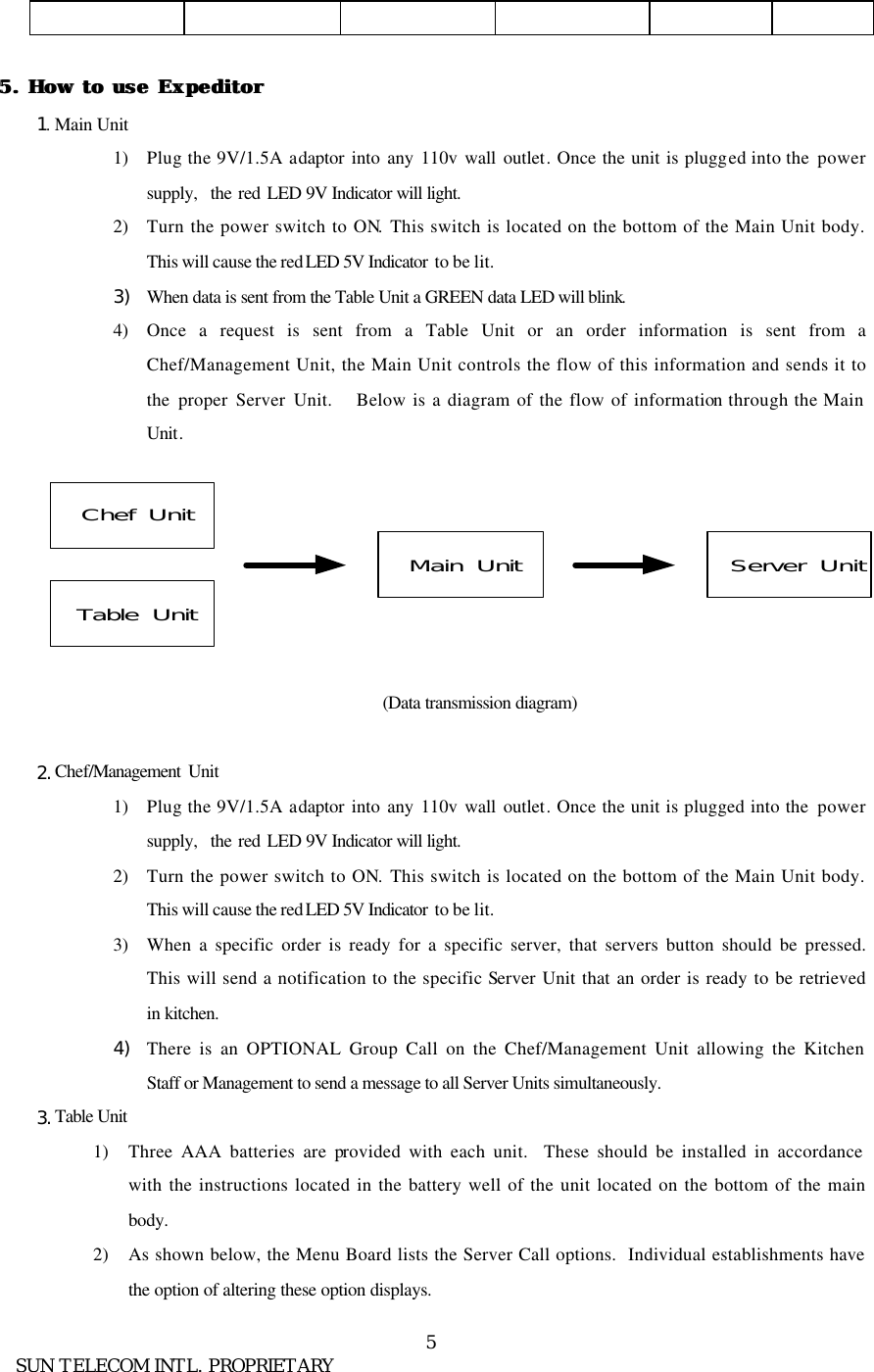
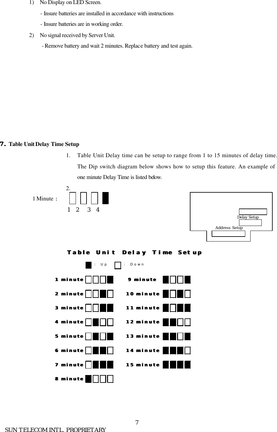
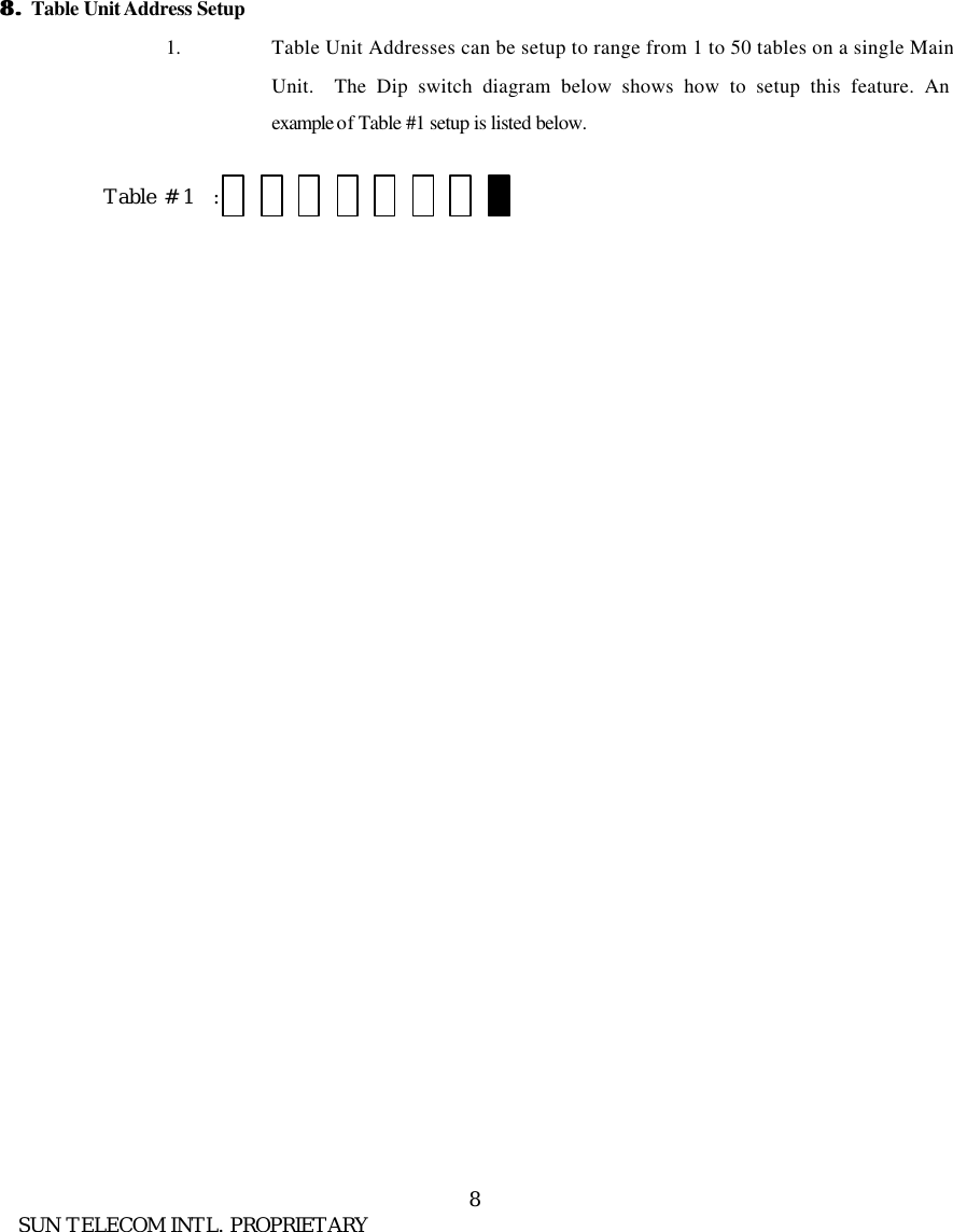
User Manual
Discussion / Help
Navigation