Hantel WWC1000 Restaurant Wireless Data Management System User Manual manual eng
Hantel Co., Ltd. Restaurant Wireless Data Management System manual eng
Hantel >
User Manual

SUN TELECOM INTL. PROPRIETARY 1
EXPEDITOR EXPEDITOR OperationsOperations
ManualManual
SUN TELECOM INTL. PROPRIETARY 2
- Table of Contents -
1. What is Expeditor?
2. Expeditor Components
3. How to install Expeditor
4. Specifications
5. How to use The Expeditor
6. Troubleshooting
7. How to set up delay timing for Table Unit
8. Table Unit Delay timer set up
9. How to set up Chef Unit addresses
10. Warnings
SUN TELECOM INTL. PROPRIETARY 3
1. What is The EXPEDITOR?
EXPEDITOR is a system designed to transfer data within a limited area such as a restaurant.
This unique system increases the servers ability to service customers. This is done through increasing the
efficiency of the server.
22. EXPEDITOR Components.
1. Main Unit – Unit Body -1 ea, Antenna-2 ea, Bracket-4 ea, Screw (small) for Bracket-8 ea (3*8mm)
Screw (Big) for fix-4 ea (4*20mm), Foot (rubber) for Housing-4 ea (20*20*3mm)
2. Chef Unit – Unit Body -1 ea, Antenna –1 ea, Bracket-4 ea, Screw (small) for Bracket-8 ea (3*8mm)
Screw (Big) for fix-4 ea (4*20mm), Foot (rubber) for Housing-4 ea (20*20*3mm)
3. Table Unit- Unit Body -50 ea, Menu Boards-50 ea, AAA batteries-150 ea.
4. Server Unit - Server Units-5 ea, AAA batteries -5 ea, Server band-5 ea, Holder-5 ea, Chain-1 ea,
Server Unit Manual – 1 ea.
5. EXPEDITOR Operations Manual - 1 ae.
3. 3. How to Install Expeditor.
1. Main Unit
1) Install brackets to Main Unit using the small screws. The brackets are installed to the sides
of the Main Unit. After installing mounting brackets to Main Unit, the unit can be mounted
to the wall.
2) Connect the 9V/1.5A power transformer to the Main Unit using the barrel connector end of
the power supply. Connect the other end of the power transformer to a standard 110v wall
outlet.
2. Chef Unit
1) Install brackets to Main Unit using the small screws. The brackets are installed to the sides of
the Main Unit. After installing mounting brackets to Main Unit, the unit can be mounted to the
wall.
2) Connect the 9V/300-500mA power transformer to the Main Unit using the barrel connector end of
the power supply. Connect the other end of the power transformer to a standard 110v wall outlet
3. Table Unit
1) Install 3 x AAA batteries in accordance with instructions on the bottom of the unit body.
Install Menu board to the top of the Table Unit body. Turn power switch to ON located on

SUN TELECOM INTL. PROPRIETARY 4
bottom of unit body.
4. Server Unit
1) Install Server Unit batteries located on the back side of the unit. The Server Unit can be worn
in the server band or can be worn in a holster. The server band is an elastic wrist watch type
band that allows the server easy access to the Server Unit especially when the servers hands
are full. The holster allows the Server Unit to be clipped to a piece of clothing.
4. 4. Specifications
1. Main Unit
1) The Main Unit controls the flow of messaging traffic within the establishment. The Main
Unit receives requests from the Chef/Management Unit and the Table Unit and transmits them
to the appropriate Server Unit.
3. Table Unit
1) The Table Unit has menu options labeled 1-6. When one of these options are selected, the
request is sent to the Main Unit along with the Table Unit address. The Main Unit will send
the request to the appropriate Server Unit.
4. Chef/Management Unit
1) The Chef/Management sends a request to the Main Unit. The Main Unit sends the request
along to the appropriate Server Unit. This will notify the Server that their food is ready for
pick up.
5. Server Unit
1) The Server Unit receives requests sent to it by the Main Unit. The Main Unit transfers requests
from both the Table Unit and the Chef/Management units.
5. Specification ss
EXPEDITOR Units
Specifications MAIN CHEF TABLE SERVER
Frequency 450 ~ 470 MHz
Freq. Stability 5 ppm
Data Rate 1200 bps
Output Power 100 mW 10 mW 5 mW Max.
Trans. Protocol FSK 2 Level POCSAG
PLL Frequency PLL Synthesizer
Batt. AAA 3 AAA 1
Ext. Power 9V/1.5A SMPS 9V 1.5A
Dimension 236*200*200 174*260*50 95*133*43 Mm
Transmit/Receive Transmit/Receive Transmit/Receive Transmit/Receive Receive only
SUN TELECOM INTL. PROPRIETARY 5
5. 5. How to use ExpeditorHow to use Expeditor
1. Main Unit
1) Plug the 9V/1.5A adaptor into any 110v wall outlet. Once the unit is plugged into the power
supply, the red LED 9V Indicator will light.
2) Turn the power switch to ON. This switch is located on the bottom of the Main Unit body.
This will cause the red LED 5V Indicator to be lit.
3) When data is sent from the Table Unit a GREEN data LED will blink.
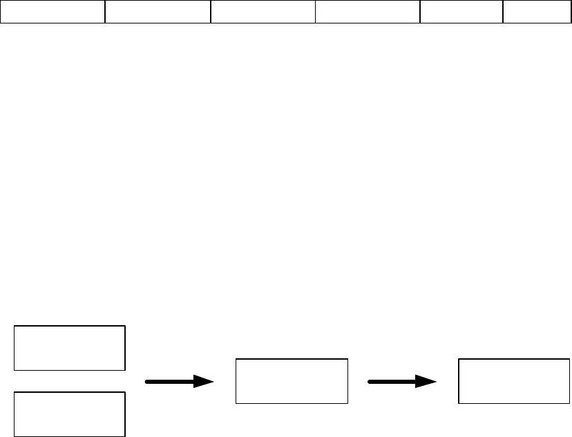
4) Once a request is sent from a Table Unit or an order information is sent from a
Chef/Management Unit, the Main Unit controls the flow of this information and sends it to
the proper Server Unit. Below is a diagram of the flow of information through the Main
Unit.
(Data transmission diagram)
2. Chef/Management Unit
1) Plug the 9V/1.5A adaptor into any 110v wall outlet. Once the unit is plugged into the power
supply, the red LED 9V Indicator will light.
2) Turn the power switch to ON. This switch is located on the bottom of the Main Unit body.
This will cause the red LED 5V Indicator to be lit.
3) When a specific order is ready for a specific server, that servers button should be pressed.
This will send a notification to the specific Server Unit that an order is ready to be retrieved
in kitchen.
4) There is an OPTIONAL Group Call on the Chef/Management Unit allowing the Kitchen
Staff or Management to send a message to all Server Units simultaneously.
3. Table Unit
1) Three AAA batteries are provided with each unit. These should be installed in accordance
with the instructions located in the battery well of the unit located on the bottom of the main
body.
2) As shown below, the Menu Board lists the Server Call options. Individual establishments have
the option of altering these option displays.
Chef Unit
Table Unit
Main Unit Server Unit
SUN TELECOM INTL. PROPRIETARY 6
<Table Unit Button Function>
No. 1 : Ready to Order
No. 2 : Need more Drinks
No. 3 : Need more Bread
No. 4 : Need Silverware/ Napkin
No. 5 : Need Assistance
No. 6 : Check please
3) Once a data selection is chosen by the customer, the Green LED lights up the show that Data is
being sent. The Table Unit sends the data and the Server Unit address information to the Main
Unit. The Main Unit will send the information to the Server Unit assigned to this specific table.
4) If the Delay Feature is activated, this will be indicated by a RED LED being lit for the duration
to the delay time. No other selections may be selected during this time.
4. Server Unit
1) The Server Unit receives requests sent to it by the Table Units assigned to it and the
Chef/Management Units. These units send the data through the Main Unit.
2) More information is available in the Server Unit Operations Manual
6. 6. Troubleshooting
1. Main Unit
1) No Power.
- Insure that the Power Supply Unit is of proper type. (9V/1.5A).
- Insure that the power supply is plugged into the unit a the wall.
- insure that the Power Switch is in the ON position.
2. Chef Unit
1) No Power.
- Insure that the Power Supply Unit is of proper type. (9V/300-500mA ).
- Insure that the power supply is plugged into the unit a the wall.
- insure that the Power Switch is in the ON position.
3. Table Unit
1. No Power to unit.
- Insure batteries are installed according to the instructions on bottom of unit
- Insure that the batteries are in working order.
- Insure that power switch is in the ON position
2. No Transmission from unit.
- Insure power switch on bottom of unit is in the ON position.
- Insure that the batteries are installed properly and in working order.
- Insure that Delay Function is in the OFF position
4. Server Unit
SUN TELECOM INTL. PROPRIETARY 7
1) No Display on LED Screen.
- Insure batteries are installed in accordance with instructions
- Insure batteries are in working order.
2) No signal received by Server Unit.
- Remove battery and wait 2 minutes. Replace battery and test again.
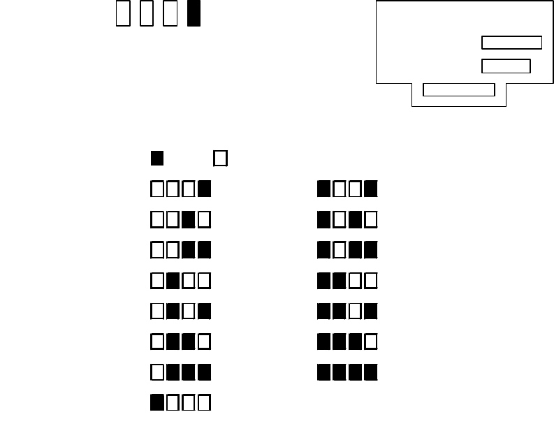
7. 7. Table Unit Delay Time Setup
1. Table Unit Delay time can be setup to range from 1 to 15 minutes of delay time.
The Dip switch diagram below shows how to setup this feature. An example of
one minute Delay Time is listed below.
2.
1 Minute :
1 2 3 4
: Up : Down
1 minute1 minute 9 minute9 minute
2 minute2 minute 10 minute10 minute
3 minute3 minute 11 minute11 minute
4 minute4 minute 12 minute12 minute
5 minute5 minute 13 minute13 minute
6 minute6 minute 14 minute14 minute
7 minute7 minute 15 minute15 minute
8 minute8 minute
Table Unit Delay Time SetupTable Unit Delay Time Setup
Address Setup
Delay Setup

SUN TELECOM INTL. PROPRIETARY 8
8. 8. Table Unit Address Setup
1. Table Unit Addresses can be setup to range from 1 to 50 tables on a single Main
Unit. The Dip switch diagram below shows how to setup this feature. An
example of Table #1 setup is listed below.
Table # 1 :
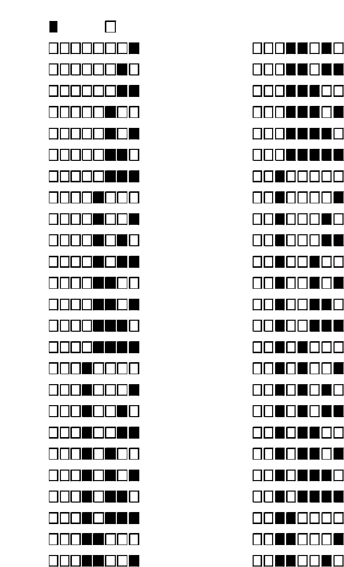
SUN TELECOM INTL. PROPRIETARY 9
1 2 3 4 5 6 7 8
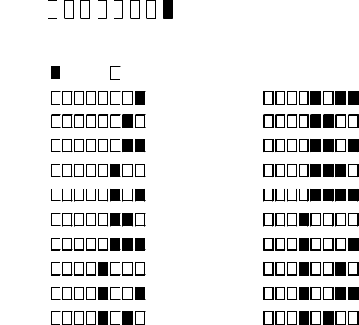
9. Chef9. Chef/Management/Management Unit Unit Address Setup Address Setup ( Option )( Option )
1. Chef/Management Unit Addresses can be setup to range from 2 to 20 Units if more than one is required
: Up : Down
5678 5678
11 2626
22 2727
33 2828
44 2929
55 3030
66 3131
77 3232
88 3333
99 3434
1010 3535
1111 3636
1212 3737
1313 3838
1414 3939
1515 4040
1616 4141
1717 4242
1818 4343
1919 4444
2020 4545
2121 4646
2222 4747
2323 4848
2424 4949
2525 5050
Table Unit Address SetupTable Unit Address Setup
SUN TELECOM INTL. PROPRIETARY 10
for operations. The Dip switch diagram below shows how to setup this feature. An example of adding
units 2 through 20 setup is listed below. .
1:
1 2 3 4 5 6 7 8
10. 10. WarningsWarnings
1. Do Not open outer body of any of the Expeditor Units. These units contain sensitive
electronics and disturbance can potentially cause failure of that unit. Electric shock can
also result from opening the outer cover of the Main and Chef/Management Units. If you
are experiencing problems and feel that repair is needed, please contact the manufacturer
or an authorized repair facility.
Sun Telecom International, Inc.
11321 Decimal Drive, Louisville, KY 40299
Phone: 502-240-0255 Fax: 502-261-9234
: Up : Down
5678 5678
11
22
33
44
55
66
77
88
99
1010
Chef/Management Unit Address SetupChef/Management Unit Address Setup
1111
1212
1313
1818
1919
2020
1414
1515
1616
1717
Notice: To comply with FCC RF exposure requirement,s, install the main unit at the location which can maintain at
least 20cm separation distance between all persons. Use only the antennas that are supplied with the unit. Any
modifications or changes not expressly approved by the party responsible for compliance could void the user;s
authority to operate the equipment.