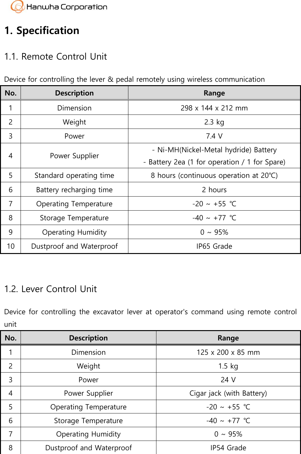
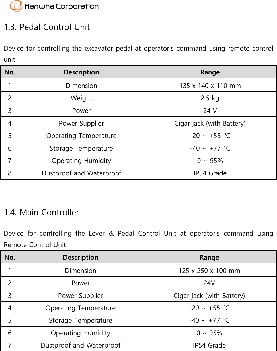
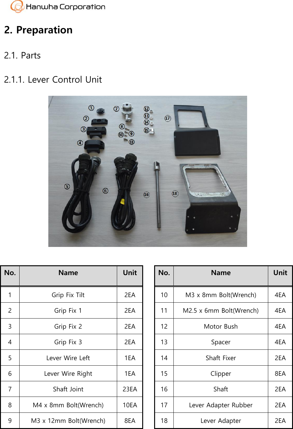
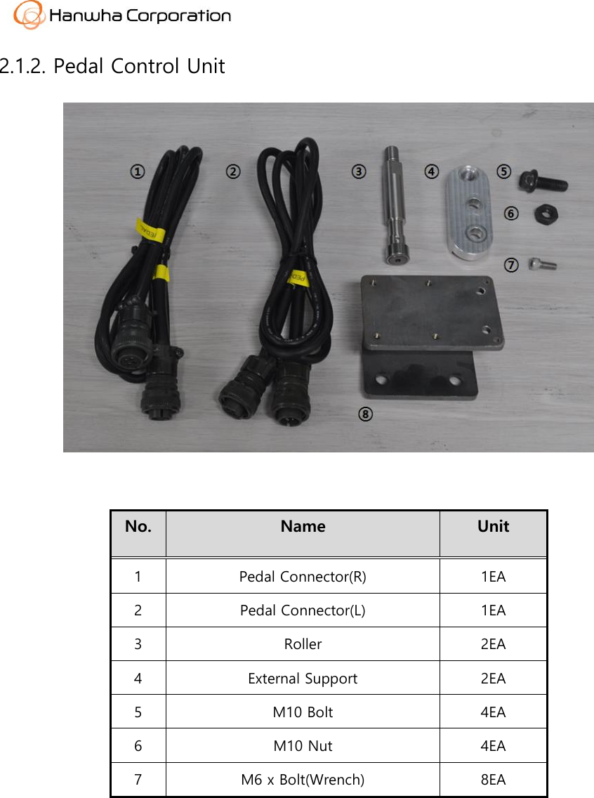
Hanwha Asan 1 Plant DJO-AR-DEF Remote Control Unit User Manual
Hanwha Corporation Asan 1 Plant Remote Control Unit
UserManual.wiki
>
Hanwha Asan 1 Plant
>
DJO AR DEF User Manual
User Manual
Navigation menu
Upload a User Manual
Namespaces
Wiki Guide
HTML
PDF
Info
Views
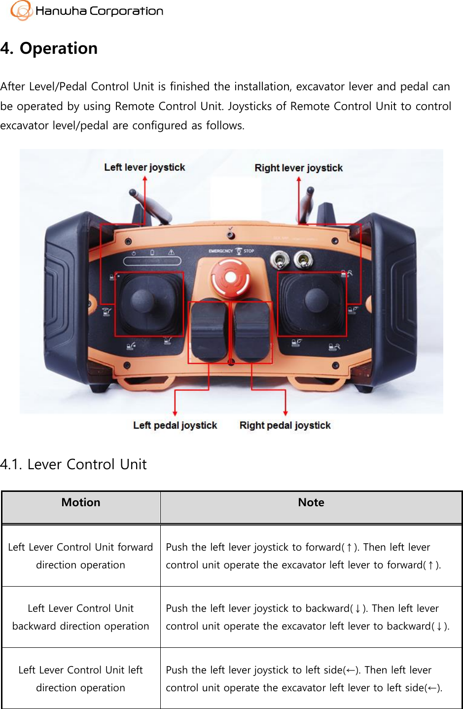
User Manual
Discussion / Help
Navigation
![2.2. Tools [ Box tool set ] [ Wrench set ] No. Name Unit 1 Box tool set 1SET 2 Wrench set 1SET](https://usermanual.wiki/Hanwha-Asan-1-Plant/DJO-AR-DEF/User-Guide-3122051-Page-6.png)