Hanwha Asan 1 Plant DJO-AR-DEF Remote Control Unit User Manual
Hanwha Corporation Asan 1 Plant Remote Control Unit
User Manual

Specification & Operation
Manual
(Remote Control Unit, Lever Control Unit,
Pedal Control Unit, Main Controller)
This document is property of Hanwha and disclosure, reproduction or duplication in whole or in
part is prohibited without its authorization. Use for the data contained in this document is
permitted only for manufacturing on Hanwha's behalf. In case of controversial interpretation of
the provisions herein contained, Hanwha shall guard legally its right.

1. Specification
1.1. Remote Control Unit
Device for controlling the lever & pedal remotely using wireless communication
No.
Description
Range
1
Dimension
298 x 144 x 212 mm
2
Weight
2.3 kg
3
Power
7.4 V
4
Power Supplier
- Ni-MH(Nickel-Metal hydride) Battery
- Battery 2ea (1 for operation / 1 for Spare)
5
Standard operating time
8 hours (continuous operation at 20℃)
6
Battery recharging time
2 hours
7
Operating Temperature
-20 ~ +55 ℃
8
Storage Temperature
-40 ~ +77 ℃
9
Operating Humidity
0 ~ 95%
10
Dustproof and Waterproof
IP65 Grade
1.2. Lever Control Unit
Device for controlling the excavator lever at operator's command using remote control
unit
No.
Description
Range
1
Dimension
125 x 200 x 85 mm
2
Weight
1.5 kg
3
Power
24 V
4
Power Supplier
Cigar jack (with Battery)
5
Operating Temperature
-20 ~ +55 ℃
6
Storage Temperature
-40 ~ +77 ℃
7
Operating Humidity
0 ~ 95%
8
Dustproof and Waterproof
IP54 Grade

1.3. Pedal Control Unit
Device for controlling the excavator pedal at operator's command using remote control
unit
No.
Description
Range
1
Dimension
135 x 140 x 110 mm
2
Weight
2.5 kg
3
Power
24 V
4
Power Supplier
Cigar jack (with Battery)
5
Operating Temperature
-20 ~ +55 ℃
6
Storage Temperature
-40 ~ +77 ℃
7
Operating Humidity
0 ~ 95%
8
Dustproof and Waterproof
IP54 Grade
1.4. Main Controller
Device for controlling the Lever & Pedal Control Unit at operator's command using
Remote Control Unit
No.
Description
Range
1
Dimension
125 x 250 x 100 mm
2
Power
24V
3
Power Supplier
Cigar jack (with Battery)
4
Operating Temperature
-20 ~ +55 ℃
5
Storage Temperature
-40 ~ +77 ℃
6
Operating Humidity
0 ~ 95%
7
Dustproof and Waterproof
IP54 Grade
2. Preparation
2.1. Parts
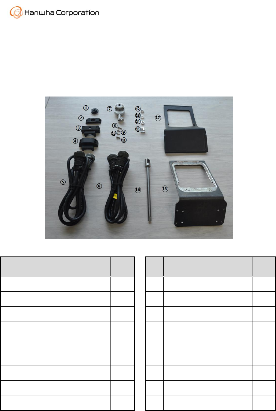
2.1.1. Lever Control Unit
No.
Name
Unit
No.
Name
Unit
1
Grip Fix Tilt
2EA
10
M3 x 8mm Bolt(Wrench)
4EA
2
Grip Fix 1
2EA
11
M2.5 x 6mm Bolt(Wrench)
4EA
3
Grip Fix 2
2EA
12
Motor Bush
4EA
4
Grip Fix 3
2EA
13
Spacer
4EA
5
Lever Wire Left
1EA
14
Shaft Fixer
2EA
6
Lever Wire Right
1EA
15
Clipper
8EA
7
Shaft Joint
23EA
16
Shaft
2EA
8
M4 x 8mm Bolt(Wrench)
10EA
17
Lever Adapter Rubber
2EA
9
M3 x 12mm Bolt(Wrench)
8EA
18
Lever Adapter
2EA
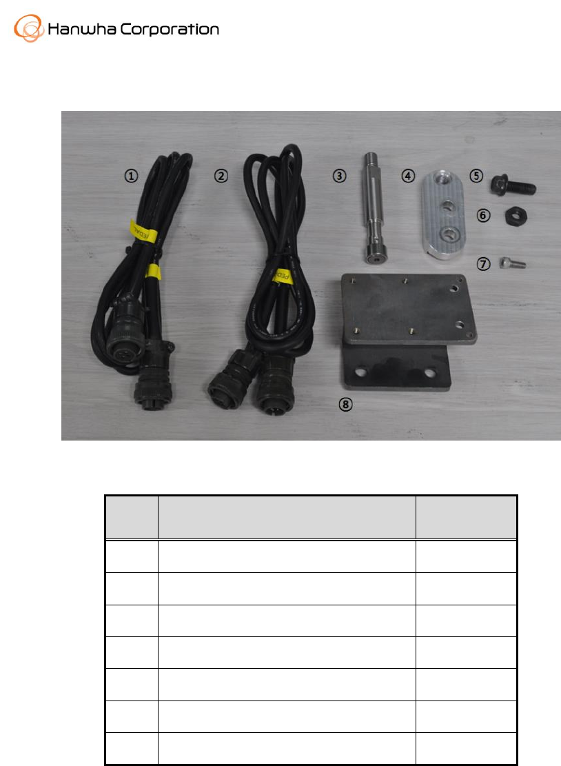
2.1.2. Pedal Control Unit
No.
Name
Unit
1
Pedal Connector(R)
1EA
2
Pedal Connector(L)
1EA
3
Roller
2EA
4
External Support
2EA
5
M10 Bolt
4EA
6
M10 Nut
4EA
7
M6 x Bolt(Wrench)
8EA
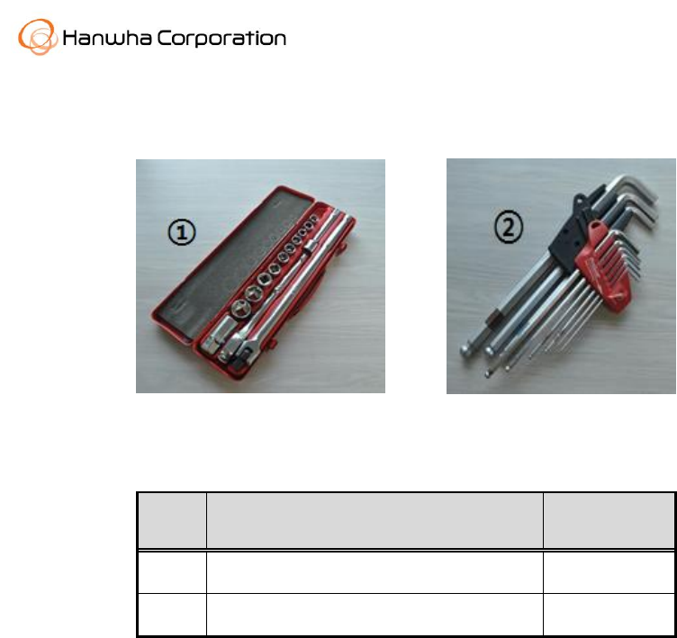
2.2. Tools
[ Box tool set ]
[ Wrench set ]
No.
Name
Unit
1
Box tool set
1SET
2
Wrench set
1SET
3. Installation
3.1. Level Control Unit
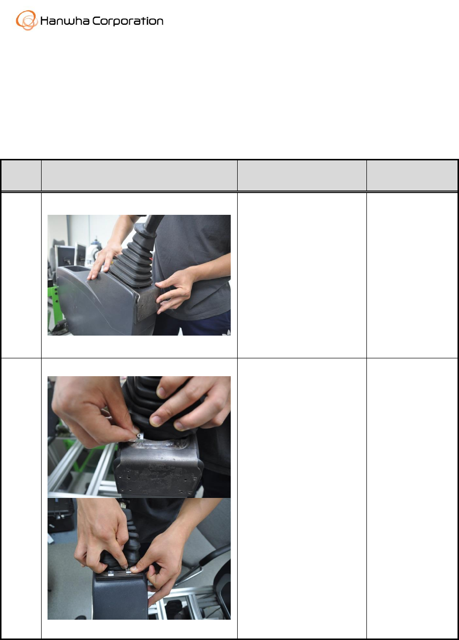
3.1.1. Lever Adapter Installation
Order
Figure
Note
Parts and Tool
1
- Put the adapter on the
adapter rubber of the
lever.
- Do not pull powerfully
to split the rubber of the
lever rubber.
- Lever Adapter
2
- When the Clippers are
inserted, Please check
that the clippers include
adapter, adapter rubber
and control stand.
- Clipper
- Wrench(M2.5)
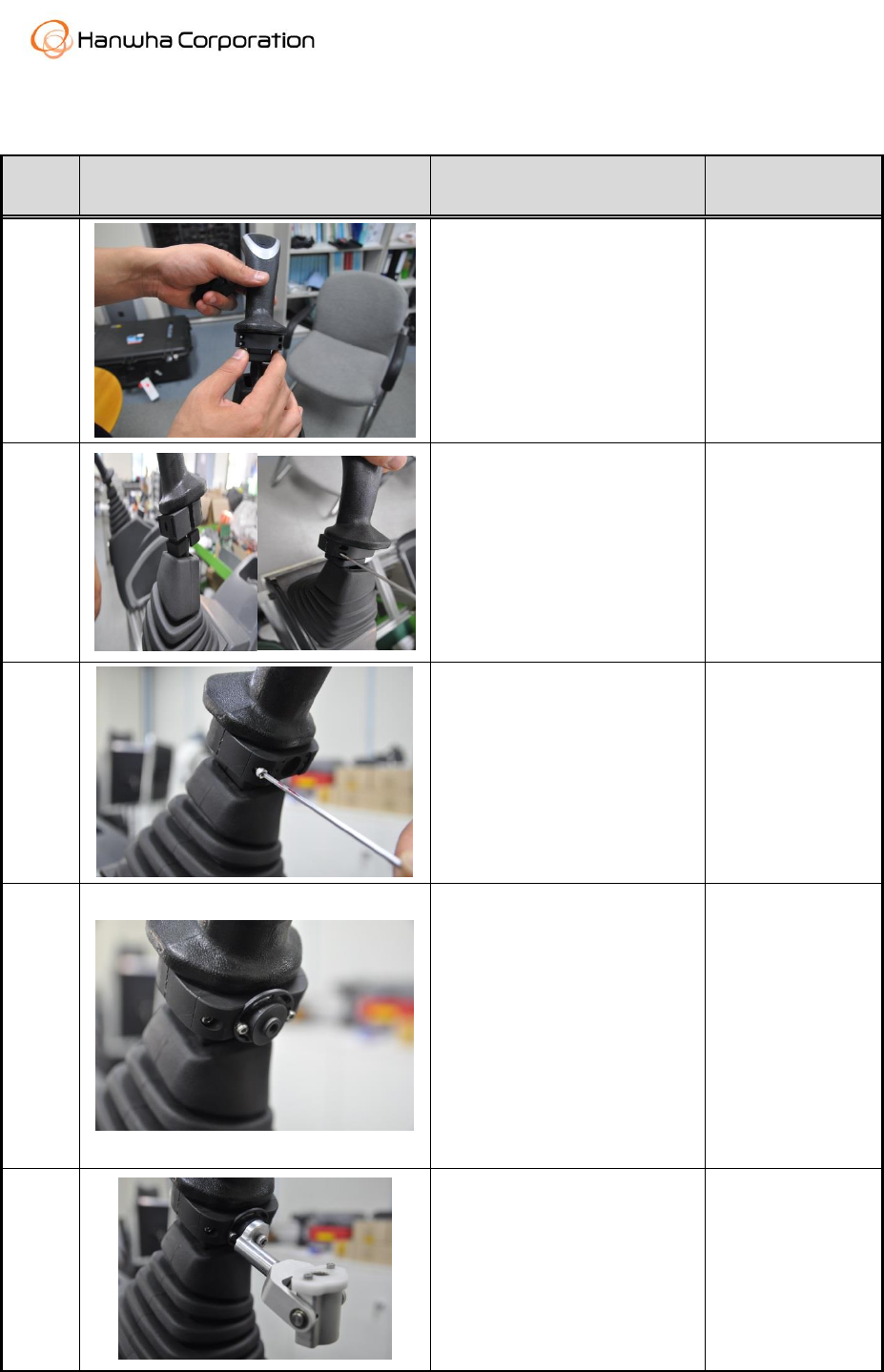
3.1.2. Lever Neck Gripper Installation
Order
Figure
Note
Parts and Tool
1
- After take off the lever
flexible rubber, Insert the
Grip Fix 3 under the lever.
- Grip Fix 3
2
- Bolting after Insert the Grip
Fix 2 where the opposite
side of the Grip Fix 3.
- Please be sure that Grip
fix2 and Grip fix3 contacted.
- Grip Fix 2
- Bolts(M3 x 4)
- Wrench(M3)
3
- Put in the Grip Fix 1 in
front of the Grip Fix 2 and
Bolting
- Grip Fix 1
- Bolts(M3 x 2)
- Wrench(M3)
4
- Put the Grip Fix Tilt into
the hole of the Grip Fix 1.
- Do not confuse the side of
the Grip Fix Tilt.
- Do not tighten up the
screws cause you will tuning
this part.
- Grip Fix Tilt
- Bolts(M2.5 x 2)
- Wrench(M2.5)
5
- Connect the Shaft joint to
Grip Fix Tilt.
- Do not tighten up the
screw also this will be tuned.
- Shaft Joint
- Screw(M4 x 1)
- Wrench(M4)
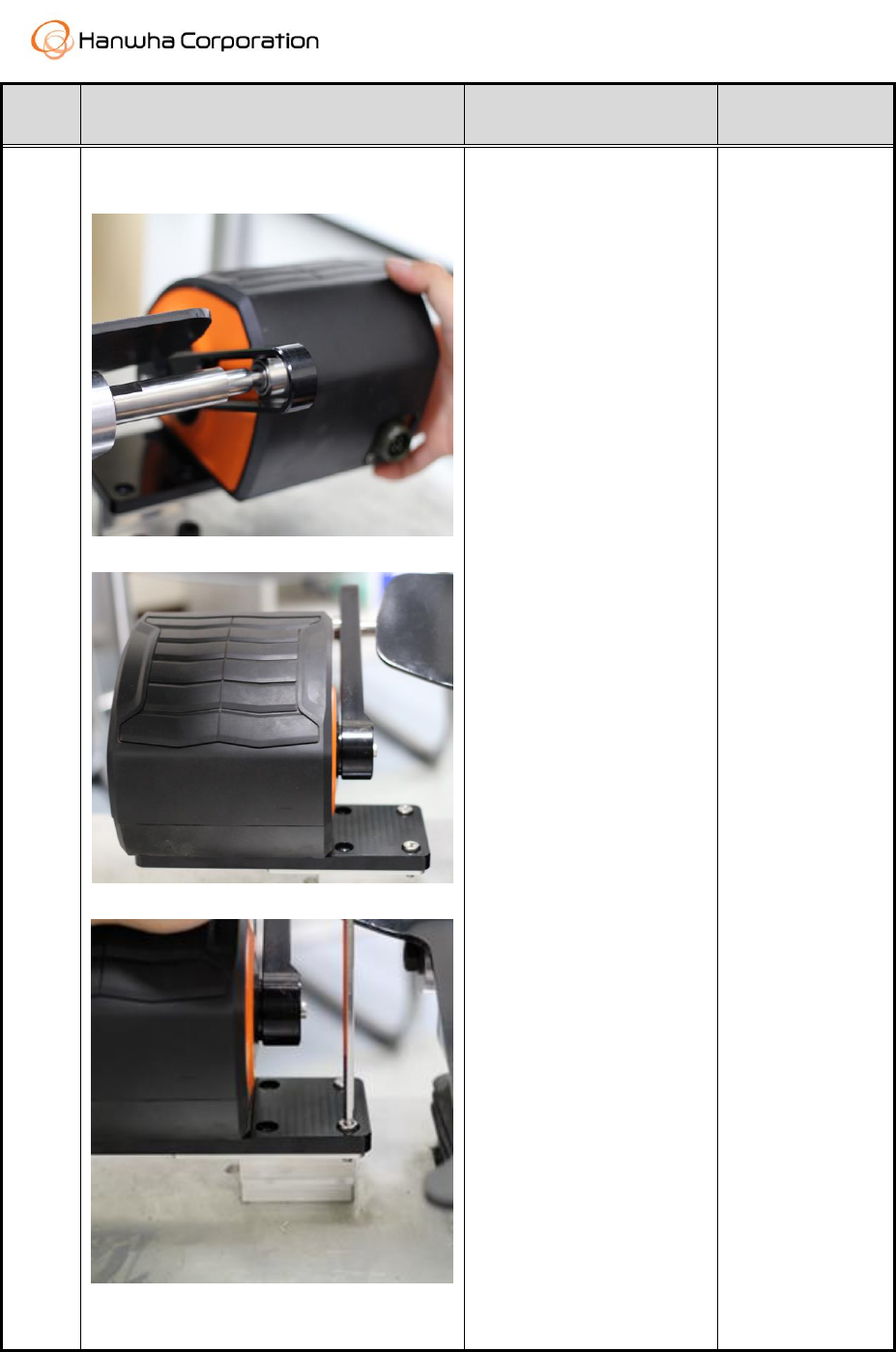
3.1.3. Installation to Adapter
Order
Figure
Note
Parts and Tool
1
- To the rotating part of
the Motor, put the Motor
Bush, Spacer, Shaft and
Shaft Fixer sequentially.
- Fix the Shaft and Shaft
Fixer using the headless
screws.
- Motor Bush
- Spacer
- Shaft
- Shaft Fixer
- Screws(M4
Headless,M3
Headless)
- Wrench(M2,
M1.5)
2
- Attach the Lever control
Unit on the Adapter.
- Please sure that Shaft
should be connected and
pass through the Shaft
Joint.
- Please mate the Align
pin and the align hole of
the Adapter When you
connect the Lever Unit
and Adapter.
- Tighten the screws on
the 4points of the Lever
control Unit.
- Shaft Joint
- Lever Control
Unit with Shaft
- Screws(M4 x 2)
- Wrench(M4)
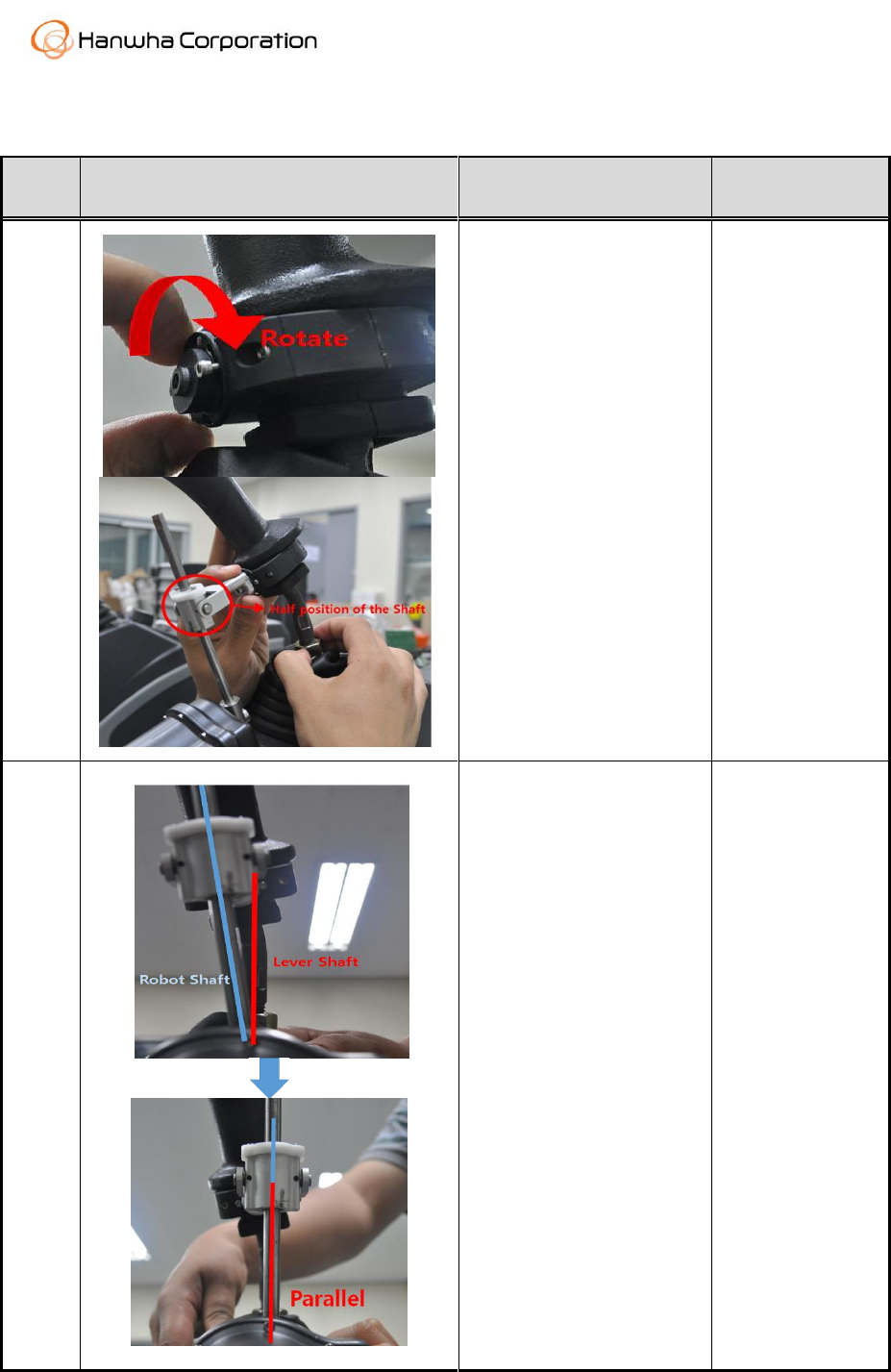
3.1.4. Horizontal Matching
Order
Figure
Note
Parts and Tool
1
- After Installation of the
Lever Control Unit, You
have the one more step
to operate machine well.
- You need to tuning the
some parts.
- First of all, tune the Grip
Fix Tilt until the Shaft
Joint positioning the half
position of the Shaft
when Lever is in neutral
position.
- Wrench(M2.5,
M4)
2
- Second, Make Parallel
between Lever shaft and
Robot Shaft for the
performance of the Lever
Control Robot.
3.2. Pedal Control Unit
3.2.1. Pedal Adapter Installation
Order
Figure
Note
Parts and Tool
1
- Take the Foot Rest off
the excavator.
- Install the Pedal
Adapter.
- Wrench(M8)
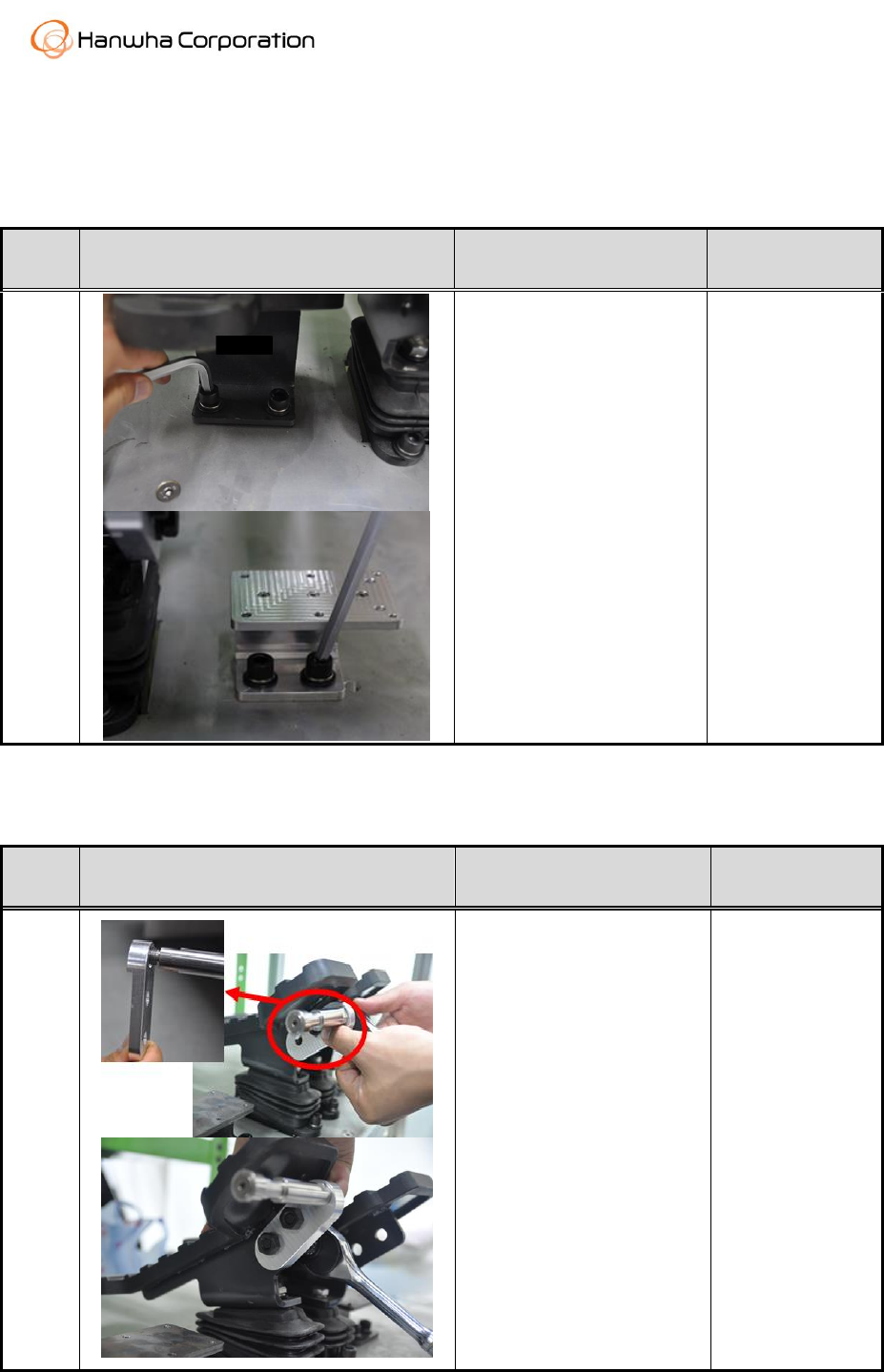
3.2.2. Pedal External Support Installation
Order
Figure
Note
Parts and Tool
1
- Assemble the Roller and
Pedal external support.
- Take off the Pedal
Handle of the Pedal .
- Install the assembled
part the opposite position
of the pedal handle like
second photo.
- Roller
- External
Support
- Box
Order
Figure
Note
Parts and Tool
2
- Match the Slide Link
and Roller attached on
the pedal.
- After match, lay the
pedal control unit on the
adapter and bolting.
- Wrench(M6)
- Screws(M6 x 4)
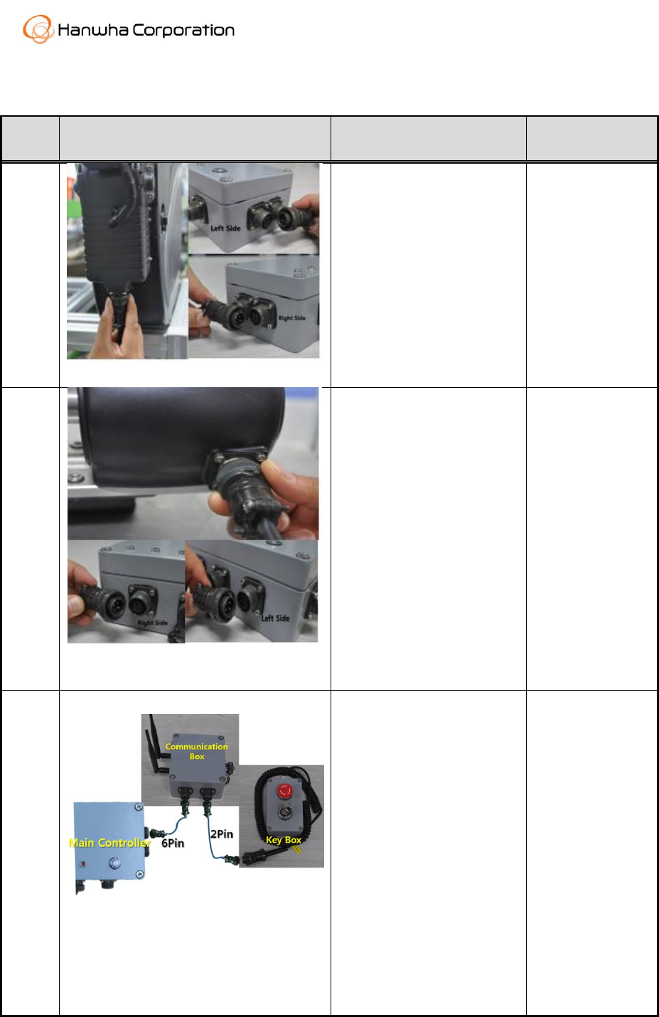
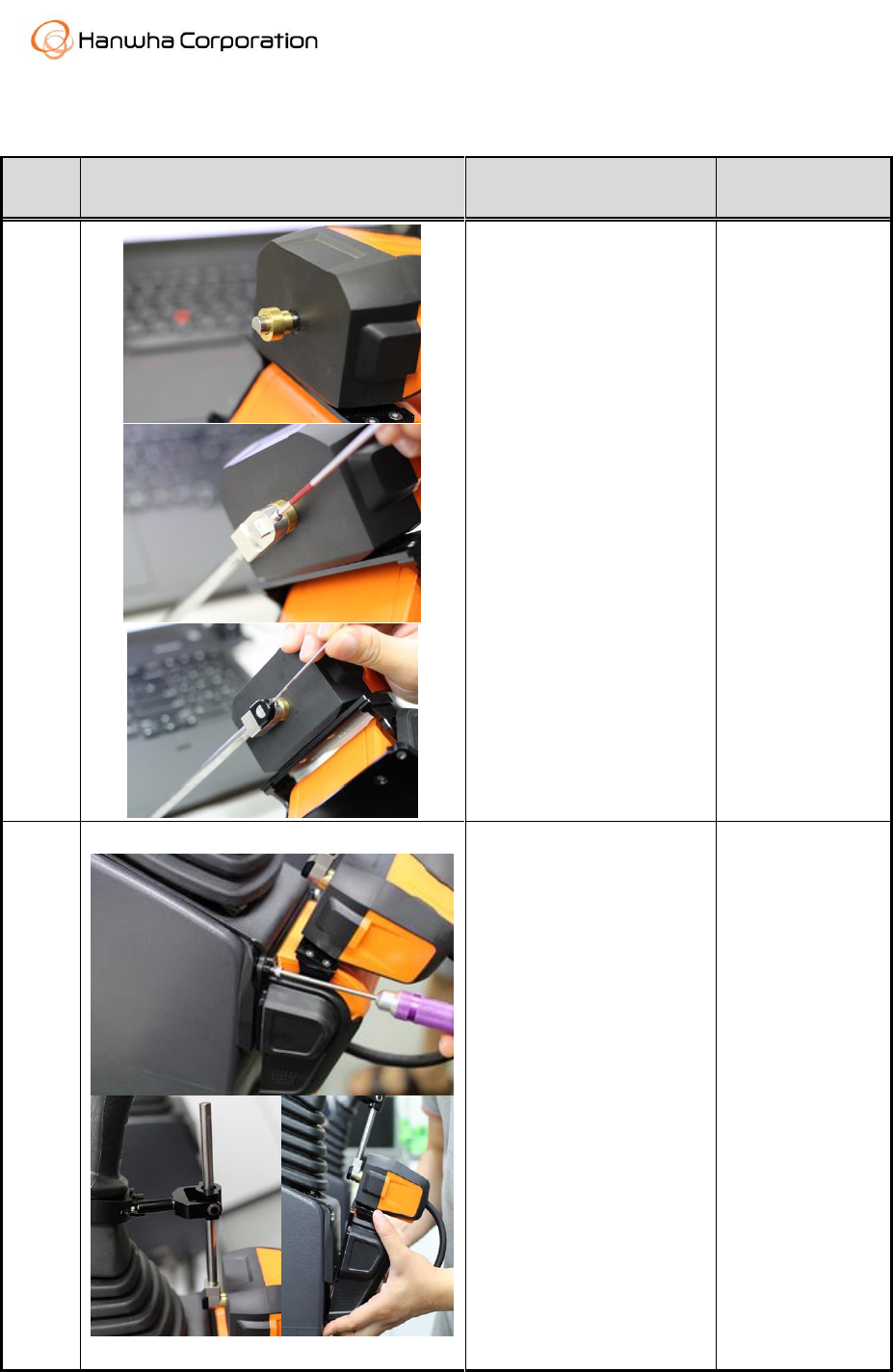
3.3. Wiring
Order
Figure
Note
Parts and Tool
1
<Lever Cable Connecting>
- Put the Lever cable to the
lever control unit.
- On the other side, of the
Cable, connect to the main
controller.
- Lever
Cable(4Pin x 2)
2
<Pedal Cable Connecting>
- Same as the Lever unit,
- Pedal unit is connected
with Main Controller.
- Pedal
Cable(4Pin x 2)
3
<Key Box and Communication Box
Cable Connecting>
- The communication box
is connected with main
controller through 6pin
cable.
- In case of Key box,
connected with
communication box
Through 2pin cable.
- Communication
Cable(6pin)
- Key box
cable(2pin)
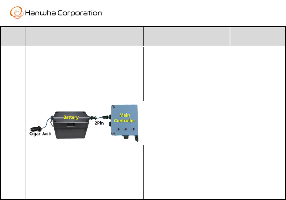
Order
Figure
Note
Parts and Tool
4
<Power Cable Connecting>
- Power cable is two type
as you see the picture, first
is Cigar jack and second is
2pin power cable.
- Cigar jack will be
connected with Excavator.
- 2Pin power cable will be
connected with main
controller and battery.
- Cigar Jack
Cable
- Power
Cable(2Pin)
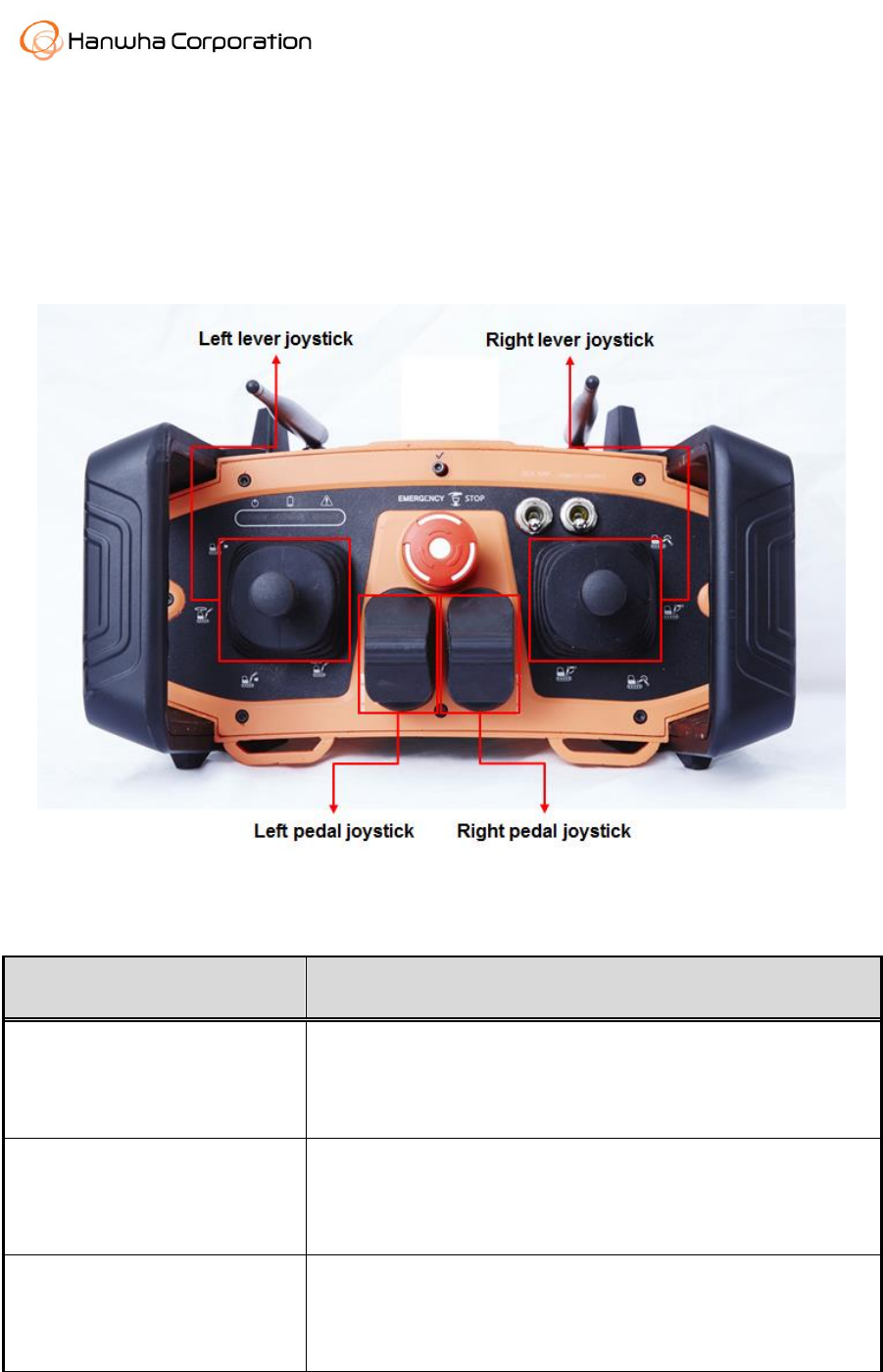
4. Operation
After Level/Pedal Control Unit is finished the installation, excavator lever and pedal can
be operated by using Remote Control Unit. Joysticks of Remote Control Unit to control
excavator level/pedal are configured as follows.
4.1. Lever Control Unit
Motion
Note
Left Lever Control Unit forward
direction operation
Push the left lever joystick to forward(↑). Then left lever
control unit operate the excavator left lever to forward(↑).
Left Lever Control Unit
backward direction operation
Push the left lever joystick to backward(↓). Then left lever
control unit operate the excavator left lever to backward(↓).
Left Lever Control Unit left
direction operation
Push the left lever joystick to left side(←). Then left lever
control unit operate the excavator left lever to left side(←).

Left Lever Control Unit right
direction operation
Push the left lever joystick to right side(→). Then left lever
control unit operate the excavator left lever to right side(→).
Right Lever Control Unit
forward direction operation
Push the right lever joystick to forward(↑). Then right lever
control unit operate the excavator right lever to forward(↑).
Right Lever Control Unit
backward direction operation
Push the right lever joystick to backward(↓). Then right lever
control unit operate the excavator right lever to
backward(↓).
Right Lever Control Unit left
direction operation
Push the right lever joystick to left side(←). Then right lever
control unit operate the excavator right lever to left side(←).
Right Lever Control Unit right
direction operation
Push the right lever joystick to right side(→). Then right lever
control unit operate the excavator right lever to right side(→).
4.2. Pedal Control Unit
Motion
Note
Left Pedal Control Unit forward
direction operation
Push the left pedal joystick to forward(↑). Then left pedal
control unit operate the excavator left pedal to forward(↑).
Left Pedal Control Unit
backward direction operation
Push the left pedal joystick to backward(↓). Then left pedal
control unit operate the excavator left pedal to
backward(↓).
Right Pedal Control Unit forward
direction operation
Push the right pedal joystick to forward(↑). Then right
pedal control unit operate the excavator right pedal to
forward(↑).
Right Pedal Control Unit
backward direction operation
Push the right pedal joystick to backward(↓). Then right
pedal control unit operate the excavator right pedal to
backward(↓).

FCC Information
This device complies with part 15 of the FCC Results. Operation is subject to the
following two conditions :
(1) This Device may not cause harmful interface, and
(2) This device must accept any interference received, including interference that
may cause undesired operation.
Note: This equipment has been tested and found to comply with the limits for CLASS B digital
device, pursuant to Part 15 of FCC Rules. These limits are designed to provide reasonable
protection against harmful interference when the equipment is operated in a commercial
environment This equipment generates, uses and can radiate radio frequency energy and, if not
installed and used in accordance with the instructions, may cause harmful interference to radio
communications. However, there is no guarantee that interference will not occur in a particular
installation. If this equipment does cause harmful interference to radio or television reception,
which can be determined by turning the equipment off and on, the user is encouraged to try
correct the interference by one or more of the following measures:
1.1. Reorient or relocate the receiving antenna.
1.2. Increase the separation between the equipment and receiver.
1.3. Connect the equipment into an outlet on a circuit different from that to which receiver is
connected.
1.4. Consult the dealer or experienced radio/TV technician for help.
WARNING
Changes or modifications not expressly approved by the manufacturer could void the
user’s authority to operate the equipment.
“CAUTION : Exposure to Radio Frequency Radiation.
Antenna shall be mounted in such a manner to minimize the potential for human
contact during normal operation. The antenna should not be contacted during operation
to avoid the possibility of exceeding the FCC radio frequency exposure limit.