Harman ACBVIBE Sound Bar User Manual ACV 2100
Harman International Industries, Inc Sound Bar ACV 2100
Harman >
Contents
- 1. User Manual-Safety Instruction
- 2. User Manual-ACV-2100
- 3. User Manual-ACV-5100
User Manual-ACV-2100
ACV-2100 Acendo Vibe™ Conferencing Sound Bar
QUICK START GUIDE
Overview
The ACV-2100 features a connector bay door that also serves as a hinged Wall Mount
Bracket, which allows easy access to the Connector Bay without having to dismount
the unit. The Wall Mount Bracket features a cutout for cable routing and straps for
cable management.
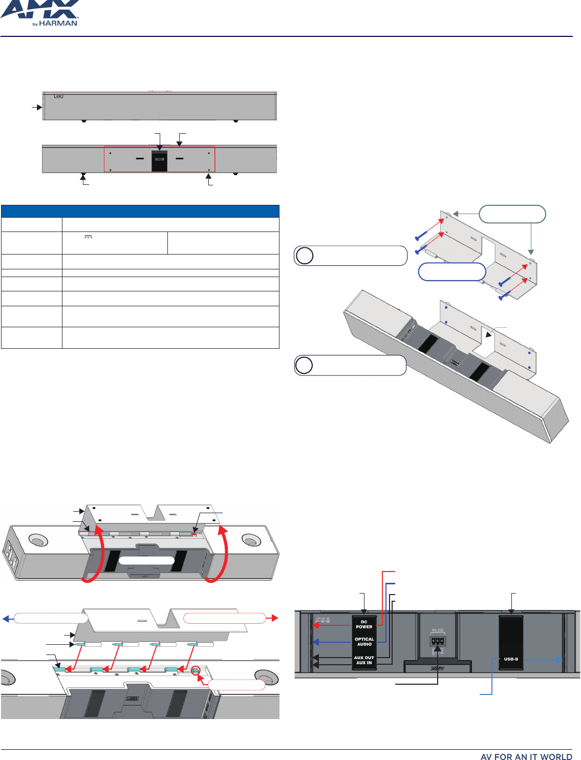
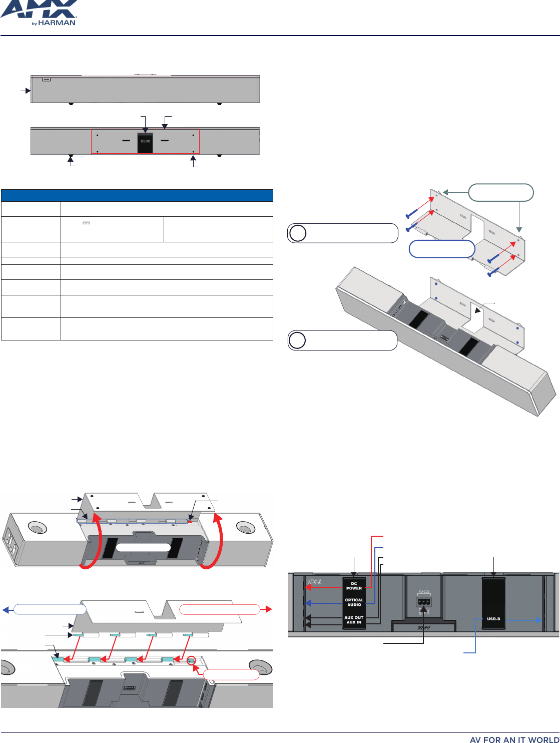
Front
Rear
mounting holes (x4)
Wall Mount Bracket
Rubber feet (removable, x2)
Side Panel
Keypad
Cable Pass-Thru
FIG. 1 ACV-2100 (FRONT/REAR VIEWS)
PRODUCT SPECIFICATIONS
MODELS AVAILABLE ACV-2100GR, Grey (FG4121-00GR)•
ACV-2100BL, Black (FG4121-00BL)•
INCLUDED
ACCESSORIES 15V • / 4A.Power Supply
Remote Control•
6' USB 2.0 Cable•
5mm Wall Mount Spacers (4)•
Lock-Down Screws (2)•
DIMENSIONS (HWD) 3" x 23 1/2" x 3 15/16" (76 mm x 590 mm x 100 mm)•
Depth with optional wall mount spacers: 4 1/8" (105 mm)•
WEIGHT 6.3 lbs (2.86 kg)
ACTIVE POWER
REQUIREMENTS
~100-240V, 1.3A max•
Only use the included power supply•
REGULATORY
COMPLIANCE
FCC 47 CFR Part 15, Subpart C / Subpart A (emissions)
EN 55024, EN 60950-1, IEC/EN/UL 60065:2014
ENVIRONMENTAL Temperature (Operating): 32° F to 113° F (0° C to 45° C)•
Temperature (Storage): -4° F to 158° F (-20° C to 70° C)•
Humidity (Operating): 5% to 85% RH non-condensing•
OPTIONAL
ACCESSORIES
CBL-USB-FL2-16, USB 2.0 16ft Extension Cable (FG10-2220-16)•
CBL-USB-FL2-33, USB 2.0 33ft Extension Cable (FG10-2220-33)•
ACR-5100, Meeting Collaboration System (FG4051-00)•
Credenza Installation
Note: To ensure highest possible sound quality, the rubber feet on the bottom panel
must remain in place for surface-mount installations.
TheACV-2100cansitonahard,atsurfacesuchasacredenza,tabletopordesk.
When choosing a surface location, consider a space that will not interfere with
workspaces or other installed devices. Connect cables as necessary - see the
Connections
section for details.
Wall Mount Installation
For best aesthetic in wall mount installations, remove the rubber feet from the bottom
panel: carefully peel each foot off of the bottom surface.
Removing the Wall Mount Bracket
Open the Wall Mount Bracket (held closed by internal magnets).1.
Press and hold the 2. Release Button to slide the Wall Mount Bracket out (over the
button) to disengage the pins on the bracket from the hinges on the unit (FIG. 2).
Bracket/Door
Hinges/Pins
Release Button
Connector Bay
FIG. 2 ACV-2100 BOTTOM VIEW - OPENING THE WALL MOUNT BRACKET
Lift the Wall Mount Bracket off of the hinges to remove (FIG. 3):3.
Bracket/Door
Pins (x4)
Hinges (x4)
Slide pins in to installSlide pins out to remove
Release Button
FIG. 3 ACV-2100 BOTTOM VIEW - REMOVING THE WALL MOUNT BRACKET
Mounting the Wall Mount Bracket and Attaching the ACV-2100
Use the Wall Mount Bracket as a template to mark the locations for the 1.
(4) mounting screws (not included). Use mounting screws and hardware
appropriateforthesurfacebeingutilizedtosecuretheBrackettothewall.
Optionally, place the four included Wall Mount Spacers between the Bracket/
Doorandthewalltocreatea5mmgapforroutingatcablesifnothidingthem
behind the drywall (see FIG. 6).
Attach the ACV-2100 to the Bracket/Door by sliding the pins on the Bracket into 2.
the hinges on the rear of the main unit (see FIG. 3):
Position the ACV-2100 with the bottom panel facing the wall and align the a.
hinges on the main unit with the pins on the Bracket.
Carefully slide the pins into the hinges, until the Bracket/door snaps into b.
place.
Note:
Press the door into place so that the last pin depresses the Release
Button, allowing the pins to slide into the hinges (see FIG. 3).
With the ACV-2100 attached to the Bracket/door, rotate the unit up to c.
its seated position. Note that the door snaps shut and is held closed via
internal magnets.
Note:
Ensure that cables do not obstruct the complete closing of the unit.
Mount the Bracket to the
wall via 4 mounting screws
Attach the ACV-2100 to the
Bracket via hinges & pins
b
a
mounting screws
(x4, not included)
mounting spacers
(x4, optional)
Note: Use M4 or #8
mounting screws
Cable Pass-Thru
FIG. 4 WALL MOUNTING THE ACV-2100
Connect cables as necessary - open the Wall Mount Bracket to access the 3.
connector bay (see FIG. 2).
Rotate the ACV-2100 into seated position. The Wall Mount Bracket is secured 4.
with magnets (see FIG. 6).
Connections
All cable connectors are located within the Connector Bay (rear panel).
For surface installations, place the unit face-down and open the Connector Bay •
Door to manage cables/connectors.
For wall-mounted installations, simply rotate the ACV-2100 unit down and away •
from the wall to access the Connector Bay.
There are two sets of connectors on the inner side panels of the Connector Bay. Each
connector is labeled on the elastic cable straps (FIG. 5):
Analog audio input
Analog audio output
Optical audio input
DC Power input
USB (Type B)
parts elbacparts elbac
RS-232 (3-pin captive wire)
FIG. 5 ACV-2100 CONNECTOR BAY
Run each cable through the cable pass-thru in the bracket/door and under the cable
straps.
ACV-2100 CONNECTIONS
DC POWER Connect the included 15V power supply to this barrel connector. Only use the
power supply included with the ACV-2100.
OPTICAL AUDIO Use this TOSLINK connector to receive Optical Stereo Input from an audio source
device.
AUX OUT Use this 1/8" mini-stereo connector to send analog stereo sound from the ACV-
2100 to an auxiliary device.
AUX IN Use this 1/8" mini-stereo connector to receive analog stereo sound from an
analog audio source device.
USB Use the USB 2.0 Type-B port to connect a PC/laptop to the ACV-2100 as a source
device.
Acendo Vibe is plug-and-play with PC/laptop using a standard UAC driver.
TheUSBconnectionisalsousedtoconguretheACV-2100viatheAcendoVibe
CongurationToolforsettingsandrmwareupdates.
RS-232 3-pin captive-wire connector provides serial communication with the Acendo
Vibe.RefertotheAcendoVibeInstructionManualforserialcommanddenitions.
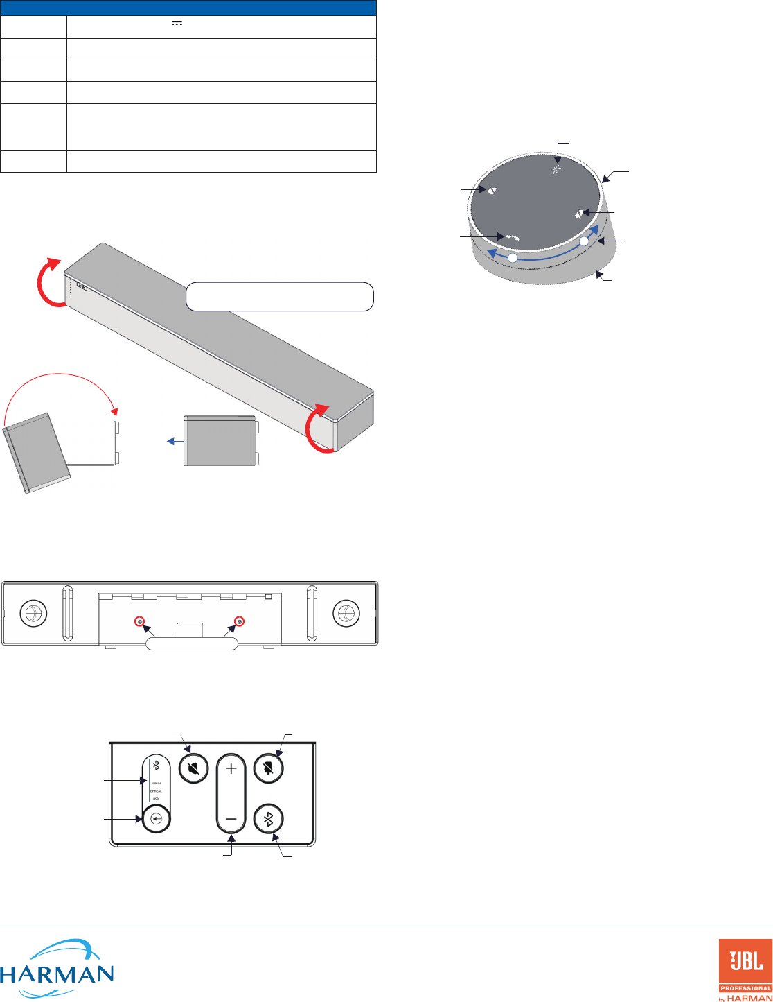
Rotating the ACV-2100 Into the Seated Position
After connecting all cables, close the Bracket to return the ACV-2100 to its seated
position. The Bracket is secured via internal magnets (FIG. 6):
Rotate the ACV-2100 into seated position
(Bracket is secured with magnets)
desolcnepo
front
FIG. 6 ROTATING THE ACV-2100 INTO ITS SEATED POSITION
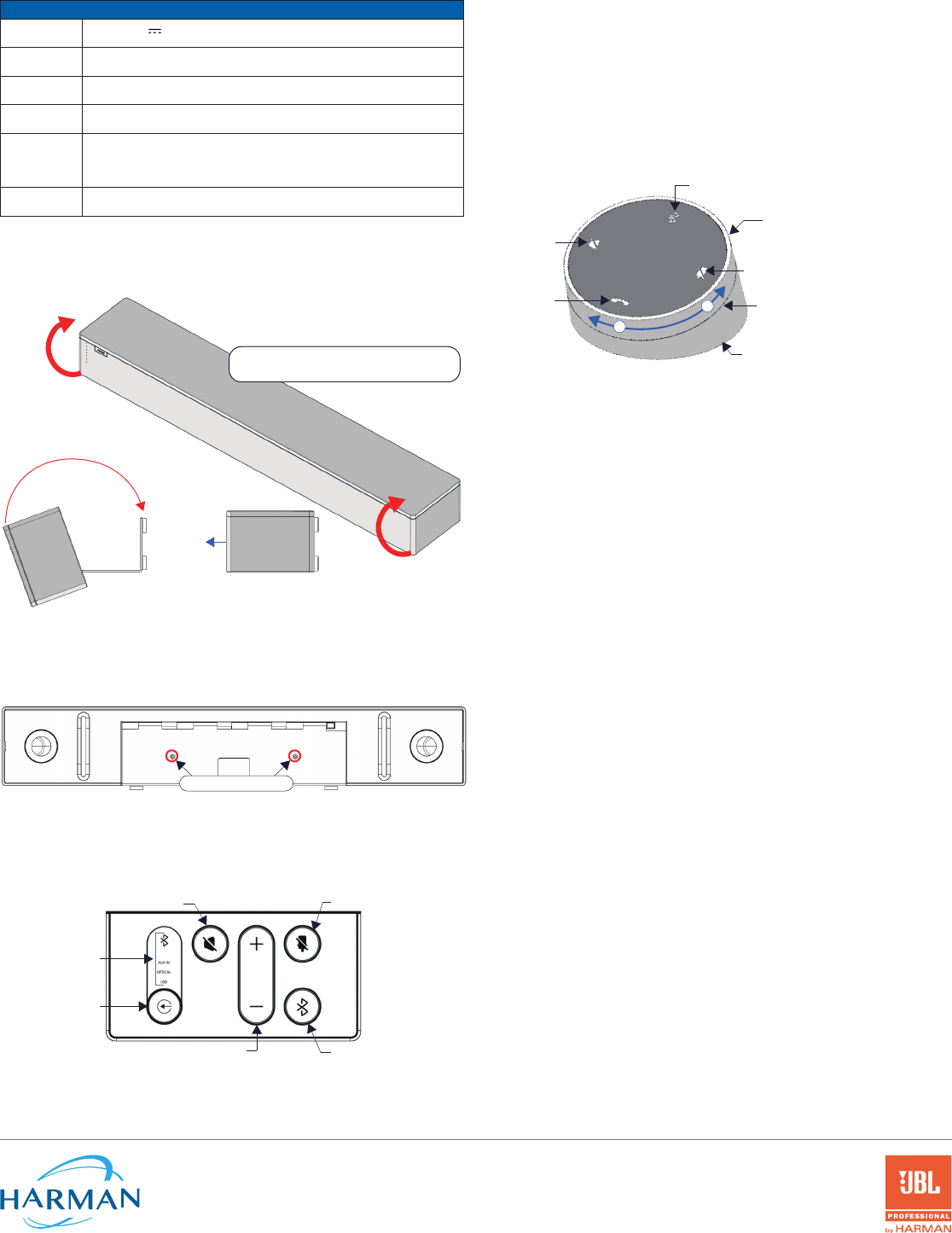
Installing Lock-Down Screws
TheACV-2100comeswithtwo(at-head)Lock-DownScrewsthatcanbeaddedafter
the ACV-2100 has been installed and connected. The Lock-Down Screws prevent
the Bracket from being opened accidentally. With the Bracket/Connector Bay Door
closed, install the Lock-Down Screws in the bottom panel (FIG. 7):
Lock-Down Screws
FIG. 7 ACV-2100 BOTTOM VIEW - LOCK DOWN SCREW LOCATIONS
Note: The Lock Down screws are not to be used to mount the ACV-2100 unit to the wall.
Side Panel Keypad
All controls and LEDs are on the left side panel of the ACV-2100 (FIG. 8):
Active Audio Source
Audio Source Select
(press to cycle through
the source options)
Mute Speaker Mute Microphone
Volume Up/Down Bluetooth Pairing
(indicates the
current selection
FIG. 8 ACV-2100 LEFT SIDE PANEL KEYPAD
Volume and Mute Controls
TheACV-2100featuresSoundbyJBL,includinga10W/channelstereoamplier,
speakers, microphones, and DSP algorithms with AEC.
Use the • Volume Up/Down buttons on either the ACV-2100 side panel or on the
remote control to adjust speaker volume.
Use the • Mute Speaker and Mute Microphone buttons to enable/disable the
speakers and microphone. Note that these buttons are lit on the ACV-2100 (and
ashontheremotecontrol)toindicatethatthesoundfunctionsaremuted.
Remote Control
The ACV-2100 includes a wireless remote control(FIG. 9):
Mute Microphone
Mute Speaker
End Call
Source Select button
(on back side)
Volume Up/Down
+
-(rotate ring to adjust)
Battery Compartment (bottom panel)
unlock & twist to open
Bluetooth Pairing
(press to pair remote to user device)
FIG. 9 ACENDO VIBE REMOTE CONTROL
Pairing the Remote Control to the Acendo Vibe
Press and hold both the 1. Source Select and Bluetooth Pairing buttons on the
remote control for 5 seconds (see FIG. 9). All LEDS on the remote control should
start blinking or remain blinking about once per second.
Press and hold both the 2. Source Select and Bluetooth Pairing buttons on the
ACV-2100 (see FIG. 8). After 3-5 seconds the LEDS on the remote control should
stopashingtoindicatetheremotecontrolhaspaired.
Note: If the remote control remains in pairing mode (all LEDS blinking) for longer than
60 seconds the remote control will go to sleep. Press any button on the remote control
to wake it up and continue with step 2.
Pairing the Acendo Vibe with a Bluetooth Source Device
Press the 1. Bluetooth Pairing button on the ACV-2100 or the remote control to
initiatepairing(seeFIG.8).TheBluetoothbuttonwillashonboththeACV-2100
and the remote control.
Note: To exit pairing mode without pairing a device, press either Bluetooth button
again for 5 seconds.
On the source device, verify that Bluetooth pairing is enabled, and look for 2.
"Acendo Vibe" (or custom discoverable name) as a found device. Select the
Acendo Vibe device for pairing.
The Bluetooth LED on the ACV-2100 side panel lights solid to indicate that the
Bluetooth device is paired.
If automatic switching is disabled, use the Source Select button on the ACV-2100
to select Bluetooth as the audio source (if necessary). At this point, the Bluetooth
LED is lit solid, Bluetooth audio is sent to the ACV-2100 speakers, and microphone
audio is sent to the paired Bluetooth device.
Note: Once the ACV-2100 has paired to a device, it must either be "removed" or
"forgotten" from your device's Bluetooth pairing list before it can be paired again.
Acendo Vibe Configuration Tool
TheACV-2100isconguredviatheAcendoVibeCongurationToolsoftware
(available to download from AMX). In most cases the default settings should not
require adjustment. For details, see the Acendo Vibe Instruction Manual, available to
view or download from www.amx.com.
Setup Mode
InorderfortheAcendoVibeCongurationTooltocommunicatewiththeACV-2100,
the unit must be in Setup Mode. To place the ACV-2100 in Setup Mode, press the Audio
Source Select and Mic Mute keys on the ACV-2100 (see FIG. 8) simultaneously for 3
seconds. All of the LEDs blink to indicate that the unit is in Setup Mode.
Note: Press and hold the Audio Source Select and Mic Mute buttons for 3 seconds to
exit Setup mode.
Additional Documentation
ForinstructionsonconguringtheAcendoVibeviatheAcendoVibeConguration
Tool,aswellasletransfer,rmwareupdates,programmingandtroubleshootinginfo,
see the Acendo Vibe Instruction Manual, available to view or download from
www.amx.com.
Refer to AMX University for online videos that demonstrate many of the installation
steps described in this Quick Start Guide.
© 2018 Harman. All rights reserved. Modero, AMX, AV FOR AN IT WORLD, HARMAN, and their respective logos are registered trademarks of
HARMAN. Oracle, Java and any other company or brand name referenced may be trademarks/registered trademarks of their respective companies.
AMX does not assume responsibility for errors or omissions. AMX also reserves the right to alter specifications without prior notice at any time.
The AMX Warranty and Return Policy and related documents can be viewed/downloaded at www.amx.com.
3000 RESEARCH DRIVE, RICHARDSON, TX 75082 AMX.com | 800.222.0193 | 469.624.8000 | +1.469.624.7400 | fax 469.624.7153
AMX (UK) LTD, AMX by HARMAN - Unit C, Auster Road, Clifton Moor, York, YO30 4GD United Kingdom • +44 1904-343-100 • www.amx.com/eu/ REV: A
Last Revised: 1/18/2018
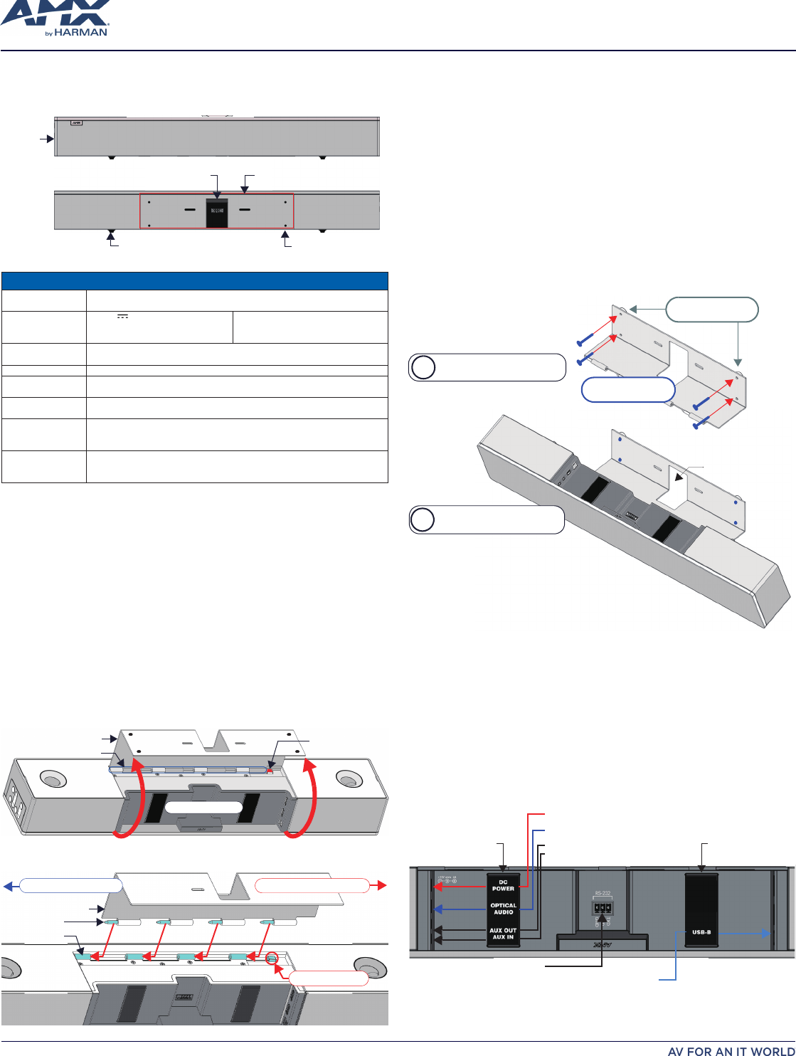
ACV-2100 (아센도 바이브™ 컨퍼런싱 사운드바)
퀵스타트 가이드
개요
ACV-2100은 경첩형 벽면 설치 브라켓 기능을 제공하는 커넥터 베이 개폐문을 적용하여, 제품을
분해하지 않고도 커넥터 베이에 접근할 수 있을 뿐만 아니라, 간편하게 설치할 수 있습니다. 벽면
설치 브라켓은 케이블 연결을 위한 커터 및 케이블 관리를 위한 케이블 스트랩을 제공합니다.
앞면
뒷면
설치 구멍(4개)
벽 설치 브라켓
고무 받침(탈부착 가능, 2개)
케이블 통과
측면 패널
키패드
그림 1 ACV-2100 (앞면/뒷면)
제품 사양
사용 가능 모델 ACV-2100GR, 그레이(FG4121-00GR)•
ACV-2100BL, 블랙(FG4121-00BL)•
포함된 액세서리 15V • / 4A. 전원공급기
리모컨•
6' USB 2.0 케이블•
5mm 벽 설치 스페이서 (4)•
고정 나사 (2)•
치수(HWD) 3" x 23 1/2" x 3 15/16" (76 mm x 590 mm x 100 mm)•
벽 설치 스페이서(옵션) 포함 깊이: 4 1/8" (105 mm)•
중량 6.3 lbs (2.86 kg)
유효 전력 요구조건 ~100-240V, 최대 1.3A•
제공된 전원공급기만 사용하십시오.•
규제 적합성 FCC 47 CFR 파트 15, 서브파트 C / 서브파트 A (방출)
EN 55024, EN 60950-1, IEC/EN/UL 60065:2014
환경 온도(작동): 32• ° F ~ 113° F (0° C ~ 45° C)
온도(보관): -4• ° F ~ 158° F (-20° C ~ 70° C)
습도 (작동): 5% ~ 85% RH 비응축•
옵션 액세서리 CBL-USB-FL2-16, USB 2.0 16ft 연장 케이블 (FG10-2220-16)•
CBL-USB-FL2-33, USB 2.0 33ft 연장 케이블 (FG10-2220-33)•
ACR-5100, 미팅 콜라보레이션 시스템 (FG4051-00)•
이 기기는 업무용(A급) 전자파적합기기로서 판매자 또는 사용자는 이 점을 주의하시기 바라며,
가정외 지역에서 사용하는 것을 목적으로 합니다.
캐비닛 설치
참고: 최고의 음질을 보장하려면 표면 설치를 위한 설치 바닥 패널에 있는 고무 받침을 그대로
유지해야 합니다.
ACV-2100은 캐비닛, 테이블 위 또는 책상과 같은 단단하고 평평한 표면에 위치시킬 수 있습니다.
표면 위치를 선택할 때 작업 공간이나 설치된 다른 장치를 방해하지 않는 공간을 고려해야
합니다. 필요한 경우 케이블을 연결하고 자세한 사항은
"연결"
을 참조하십시오.
벽 설치
벽 설치 시 바닥 패널에서 고무 받침을 제거하면 외관상 보기에 좋습니다. 바닥 표면에서 각각의
받침을 주의해서 제거하십시오.
벽 설치 브라켓 제거
벽 설치 브라켓을 엽니다(내부 자석을 통해 닫힌 상태로 고정)1.
"해제" 버튼2. 을 몇 초간 눌러 브라켓을 밀어 빼 내어(버튼 위로) 제품에 있는 경첩에서
브라켓의 핀을 분리합니다(그림 2).
벽 설치 브라켓
경첩 /핀
해제 버튼
커넥터 베이
그림 2 ACV-2100 바닥부 - 벽 설치 브라켓 개방
벽 설치 브라켓을 들어 올려 힌지에서 분리합니다(그림 3):3.
벽 설치 브라켓
핀 (4개)
경첩 (4개)
핀을 안으로 밀어 설치합니다.핀을 바깥으로 밀어 제거합니다.
해제버튼
그림 3 ACV-2100 바닥부 - 브라켓 제거
벽 설치 브라켓 설치 및 ACV-2100 부착
벽 설치 브라켓을 템플릿으로 사용해 4개의 설치 나사(미포함)를 위한 위치를 표시합니다. 1.
설치 나사와 사용 중인 표면에 적절한 하드웨어를 이용해 브라켓을 벽에 고정합니다.
추가적으로, 석고보드 뒤에서 나사가 가려지지 않는 경우 브라켓과 벽 사이에 제공된 4
개의 벽 설치 스페이서를 위치시켜 플랫 케이블 연결을 위한 5mm 간격을 만듭니다(그림
6 참조).
브라켓 위에서 메인 장치 후면에 있는 경첩 안으로 핀을 밀어 내어 ACV-2100을 브라켓에 2.
부착합니다(그림 3 참조):
바닥 패널이 벽을 향한 상태로 ACV-2100을 위치시키고 메인 장치의 경첩을 a.
브라켓의 핀과 정렬합니다.
브라켓이 딸깍 소리가 날 때까지 핀을 경첩 안으로 천천히 밀어 냅니다.b.
참고: 마지막 핀이 해제 버튼을 눌러 핀이 경첩 안으로 들어갈 수 있도록 브라켓을
누릅니다(그림 3 참조).
ACV-2100을 브라켓에 부착한 상태에서 제품을 안착된 위치까지 회전합니다. c.
브라켓에서 딸깍 소리가 나면 내부 자석을 통해 닫힌 상태로 유지됩니다.
참고:
케이블이 제품을 완전히 닫을 수 있도록 하는 것을 방해하는지
확인하십시오.
b
a
케이블 통과
4개의 설치 나사를 이용해
브라켓을 벽에 설치
ACV-2100을 경첩 및 핀을
이용해 브라켓에 부착
설치 스페이서
(4개, 옵션)
설치 나사
(x4, 미포함)
참고: M4 또는 #8 설치
나사를 사용하십시오.
그림 4 ACV-2100 벽면 설치
필요한 경우 케이블을 연결합니다(커넥터 베이 내부 - 그림 2 참조).3.
ACV-2100을 안착된 위치로 회전합니다. 브라켓은 자석으로 고정됩니다(그림 6).4.
제품 연결
모든 커넥터는 커넥터 베이 안에 있습니다(뒷면)
표면 설치인 경우 제품을 아래로 한 상태에서 커넥터 베이 도어를 열어 케이블/커넥터를 •
관리합니다.
벽면 설치의 경우 ACV-2100을 아래로 돌려 벽에서 멀리하면 커넥터 베이에 접근할 수 •
있습니다.
커넥터 베이의 내부 측면 패널에는 커넥터 2세트가 있습니다. 각각의 커넥터는 탄성 케이블
스트랩으로 라벨이 부착됩니다.
아날로그 오디오 입력
아날로그 오디오 출력
광케이블 오디오 입력 연결
전원 어댑터 연결
USB( 타입 B)
RS-232 (3핀 전용선)
케이블 고정 스트랩 케이블 고정 스트랩
그림. 5 ACV-2100 커넥터 베이
각각의 케이블은 브라켓/도어와 케이블 스트랩 아래에 있는 케이블 통로를 통과합니다.
ACV-2100 제품 연결
DC 전원 제공된 15V 전원 공급기를 배럴 커넥터에 연결합니다. ACV-2100와 함께 제공된
전원공급기만 사용하십시오.
광 케이블 오디오 TOSLINK 커넥터를 사용해 오디오 소스 장치에서 광학 스테레오 입력을 수신합니다.
AUX OUT 1/8" 미니 스테레오 커넥터를 이용해 ACV-2100의 아날로그 스테레오 사운드를 보조
장치로 전송합니다.
AUX IN 1/8" 미니 스테레오 커넥터를 이용해 아날로그 오디오 소스 장치에서 아날로그 스테레오
사운드를 수신합니다.
USB USB 2.0 타입-B 포트를 이용해 PC/노트북을 ACV-2100에 소스 장치로 연결합니다.
아센도 바이브는 표준 UAC 드라이버를 이용해 PC/노트북과 플러그앤플레이로 연결할 수
있습니다.
USB 연결은 아센도 바이브를 통해 ACV-2100을 구성하는 데 사용되기도 합니다.
설정 및 펌웨어 업데이트를 위한 구성 도구.
RS-232 3핀 캡티브-와이어 커넥터는 아센도 바이브와의 직렬 통신을 제공합니다. 직렬 통신 정의에
대해서는 아센도 바이브 사용설명서를 참조하십시오.
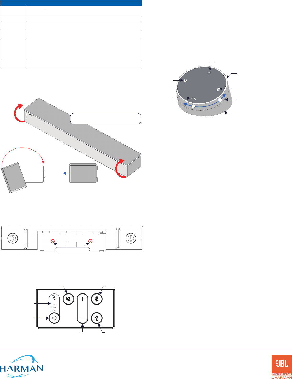
ACV-2100을 안착된 위치로 회전
모든 케이블을 연결한 후 브라켓을 닫아 ACV-2100을 안착된 위치로 되돌립니다. 브라켓은 내부
자석으로 고정됩니다(그림 6).
열림
앞면
닫힘
ACV-2100을 안착된 위치로 회전합니다
(브라켓은 자석으로 고정됩니다).
그림 6 ACV-2100을 안착된 위치로 회전
고정 나사 설치
ACV-2100에는 2개의 (평헤드) 고정 나사가 제공되며 ACV-2100을 설치 및 연결한 후에 추가될
수 있습니다. 고정 나사는 브라켓이 우발적으로 열리는 것을 방지합니다. 브라켓/커넥터 베이
도어가 닫힌 상태에서 고정 나사를 바닥 패널에 설치합니다(그림 8):
고정나사
그림 7 ACV-2100 바닥부 - 고정 나사 위치
참고: 고정 나사는 ACV-2100 장치를 벽에 설치하는 데 사용되지 않습니다.
측면 패널 키패드
모든 제어 및 LED는 ACV-2100의 좌측에 있습니다(그림 8):
스피커 음소거 마이크 음소거
볼륨 +/- 블루투스 페어링
유효 오디오 소스
(현재 선택을 표시)
오디오 소스 선택
(누르면 소스 옵션이
변경됩니다)
그림. 8 ACV-2100 좌측 패널 키패드
볼륨 및 음소거 제어
ACV-2100은 10W/채널 스테레오 앰프, 스피커, 마이크 및 AEC와의 DSP 알고리즘을 포함해
JBL 사운드를 제공합니다.
ACV-2100 측면 패널이나 리모컨에 있는 • "볼륨 +/-" 버튼을 이용해 스피커 볼륨을
조정합니다.
스피커 음소거• 및 마이크 음소거는 스피커와 마이크를 활성화/비활성화합니다. ACV-
2100에서 이 버튼이 켜져 있는 경우(리모컨에서 점멸) 사운드 기능이 음소거되었음을
나타냅니다.
리모컨
ACV-2100은 무선 리모컨을 제공합니다(그림 9):
마이크 음소거
스피커 음소거
통화 종료
소스 선택 버튼
(뒷면)
볼륨 +/-
(링을 돌려 조정)
+
-
배터리함(바닥 패널)
잠금 해제 및 비틀어 개방
블루투스 페어링
(누르면 리모컨을 사용자 장치에 연결합니다)
그림 9 아센도 바이브 리모컨
리모컨을 아센도 바이브에 페어링
리모컨에서 1. "소스 선택" 및 "블루투스 페어링" 버튼을 5초 간 누릅니다(그림 9 참조).
리모컨의 모든 LED가 점멸을 시작하거나 점멸 상태를 유지합니다(초 당 1회).
ACV-2100에서 2. "소스 선택" 및 "블루투스 페어링" 버튼을 몇 초간 누릅니다(그림 9 참조).
3-5초 후, 리모컨의 LED가 점멸을 멈추면 리모컨이 페어링되었음을 의미합니다.
참고: 60초 이상 리모컨이 페어링 모드 상태인 경우(모든 LED 점멸) 리모컨은 슬립 상태로
전환됩니다. 리모컨의 아무 버튼이나 누르면 활성화 상태로 전환되고 2단계부터 계속 합니다.
아센도 바이브를 블루투스 소스 장치와 페어링
아센도 바이브나 리모컨의 1. 블루투스 페어링 버튼을 누르면 페어링이 시작됩니다(그림 8
참조). 블루투스 버튼은 ACV-2100과 리모컨 모두에서 점멸합니다.
참고: 장치를 페어링하지 않고 페어링 모드를 종료하려면 블루투스 버튼을 5초간
누릅니다.
소스 장치에서 블루투스 페어링이 활성화 상태인지 확인한 후 발견된 장치 중 "아센도 2.
바이브" (또는 쉽게 구분할 수 있는 이름)를 찾습니다. 페어링을 위해 아센도 바이브를
선택합니다.
ACV-2100 측면 패널의 블루투스 LED가 계속 켜져 있는 경우 블루투스 장치가
페어링되었음을 의미합니다.
자동 전환이 비활성화 상태인 경우 ACV-2100의 "소스 선택" 버튼을 이용해 블루투스를
오디오 소스로 선택합니다(필요한 경우). 이 시점에서 블루투스 LED가 계속 켜지며
블루투스 오디오가 ACV-2100 스피커로 전송되고 마이크 오디오는 페어링된 블루투스
장치로 전송됩니다.
참고: ACV-2100이 장치에 페어링되면 장치의 블루투스 페어링에서 "제거" 된 후에 다시
페어링될 수 있습니다.
아센도 바이브 구성 도구
ACV-2100은 아센도 바이브 구성 도구 소프트웨어를 통해 구성됩니다(AMX에서 다운로드해
사용 가능). 대부분의 경우 기본값 설정은 조정이 필요하지 않습니다. 자세한 사항은 아센도
바이브 사용설명서를 참조하십시오. 사용설명서는 www.amx.com에서 확인 또는 다운로드할
수 있습니다.
설정 모드
아센도 바이브 구성 도구를 ACV-2100과 통신하려면 제품은 설정 모드 상태여야 합니다. ACV-
2100을 설정 모드로 전환하려면 리모컨에서 "오디오 소스 선택" 및 "마이크 음소거" 버튼을 동시에
3초간 누릅니다(그림 9 참조). 모든 LED가 점멸하면 설정 모드 상태임을 의미합니다.
참고: "오디오 소스 선택"과 "마이크 음소거" 버튼을 3초간 누르면 설정 모드가 종료됩니다.
추가 문서
아센도 바이브 구성, 파일 전송, 펌웨어 업데이트, 프로그래밍, 문제해결 정보에 대한 지침은
아센도 바이브 사용설명서를 참조하십시오. 사용설명서는 www.amx.com에서 확인 또는
다운받을 수 있습니다.
퀵스타트 가이드에서 기술된 여러 설치 단계를 시연한 온라인 비디오는 AMX 대학을
참조하십시오.
© 2018 하만. 모든 권한 보유. 보유. Modero, AMX, AV FOR AN IT WORLD, HARMAN 및 각각의 로고는 하만의 등록상표입니다. 참조된 오라클, 자바 및 기타
회사나 브랜드명은 각 회사의 상표/등록상표입니다.
AMX는 오류나 누락에 대한 책임을 지지 않습니다. 또한 사전 공지 없이 언제든지 사양을 변경할 수 있는 권한을 가지고 있습니다.
AMX 보증 및 반품 정책과 관련 문서는 www.amx.com에서 확인 및 다운받을 수 있습니다.
3000 RESEARCH DRIVE, RICHARDSON, TX 75082 AMX.com | 800.222.0193 | 469.624.8000 | +1.469.624.7400 | fax 469.624.7153
AMX (UK) LTD, AMX by HARMAN - Unit C, Auster Road, Clifton Moor, York, YO30 4GD United Kingdom • +44 1904-343-100 • www.amx.com/eu/ 버젼: A
최종 수정 : 2018년 1월 18일
ACV-2100 Acendo Vibe™ 条形会议音箱
快速入门指南
概述
ACV-2100 配有一个接口坞门,也可以作为一个铰接的壁挂支架,使得无需拆卸即可方便地进
入接口坞。壁挂支架设有一个切口,便于电缆布线和扎带管理。
正面
背面
安装孔(4 个)
壁挂支架
橡胶垫脚(2 个,可拆卸)
电缆出入口
侧面板
键盘
图 1 ACV-2100(正面/背面视图)
产品规格
提供的型号 ACV-2100GR,灰色 (FG4121-00GR)•
ACV-2100BL,黑色 (FG4121-00BL)•
随附配件 15V • / 4A 电源
遥控器•
6' USB 2.0 电缆•
5mm 壁挂式垫片(4 个)•
锁定螺丝(2 颗)•
尺寸(高宽厚) 3" x 23 1/2" x 3 15/16" (76 mm x 590 mm x 100 mm)•
加上可选壁挂式垫片后的厚度:4 1/8" (105 mm)•
重量 6.3 lbs (2.86 kg)
电源要求 约 100-240V,最大 1.3A•
仅可使用随附的电源•
监管合规 FCC 47 CFR 第 15 部分,子部分 C/子部分 A(排放)
EN 55024, EN 60950-1, IEC/EN/UL 60065:2014
环境要求 温度(工作):32• °F 至 113°F(0°C 至 45°C)
温度(存储):-4• °F 至 158°F(-20°C 至 70°C)
湿度(工作):5% 至 85% 相对湿度,非冷凝•
可选配件 CBL-USB-FL2-16,USB 2.0 16ft 延长线 (FG10-2220-16)•
CBL-USB-FL2-33,USB 2.0 33ft 延长线 (FG10-2220-33)•
ACR-5100,会议协作系统 (FG4051-00)•
安装在书柜上
注意:为确保尽可能高的音质,底部面板上的橡胶垫脚必须保持在适合表面安装的位置。
ACV-2100 可以放置在平坦的表面,如书柜、桌面或书桌。选择表面位置时,请确保不会干扰
工作空间或其他固定设备的空间。根据需要接线 - 有关详情,请参阅
连接
一节。
壁挂式安装
为确保壁挂式安装呈现最美的视觉效果,请从底部面板上取下橡胶垫脚:小心地将每只垫脚从
底面剥离。
卸下壁挂支架
打开壁挂支架(其由内部磁铁保持关闭状态)。1.
按住2. 释放按钮将壁挂支架滑出(在按钮上方),以将支架上的销钉从设备上的铰链上脱开
(图 2)。
支架/门
铰链/销钉
释放按钮
接口坞
图 2 ACV-2100 底部视图 - 打开壁挂支架
将壁挂支架从铰链上卸下(图 3):3.
支架/门
销钉(4 颗)
铰链(4 个)
将销钉滑入以进行安装 将销钉滑出即可移除
释放按钮
图 3 ACV-2100 底部视图 - 卸下壁挂支架
安装壁挂支架并接上 ACV-2100
使用壁挂支架作为模板来标记四颗安装螺丝(不赠送)的位置。使用适用于所用表面的安1.
装螺丝和工具将支架固定到墙上。
另外,如果不将它们隐藏在干式墙后面,则将 4 个壁挂式垫片放置在支架/门和墙壁之间
以形成用于引导扁平电缆的 5mm 间隙(见图 6)。
通过将支架/门上的销钉滑入主机后部的铰链(见图 3),将 ACV-2100 连接到支架上:2.
将 ACV-2100 的底部面板放在墙上,并将主机上的铰链与支架上的销钉对齐。a.
小心地将销钉滑入铰链,直到支架/门卡入到位。b.
注意:将门压入到位,使最后一个销钉压下释放按钮,使销钉滑入铰链中(见图 3)。
将 ACV-2100 连接到支架/门上,然后旋转至其坐姿。请注意,此时门将关闭并通c.
过内部磁铁保持关闭。
注意:确保电缆不会阻碍设备完全关闭。
b
a
电缆出入口
通过 4 颗安装螺丝将支架
安装到墙上
通过铰链和销钉将
ACV-2100 连接到支架上
安装垫片
(4 个,选购)
安装螺丝
(4 颗,不赠送)
注意:请使用 M4 或 8
号安装螺丝
图 4 壁挂式安装 ACV-2100
根据需要接线 - 打开壁挂支架以进入接口坞(见图 2)。3.
将 ACV-2100 旋转到坐姿。壁挂支架用磁铁固定(见图 6)。4.
连接
所有电缆接口均位于接口坞(后面板)内。
对于表面安装,请将设备面朝下放置并打开接口坞门以管理电缆/接口。•
对于壁挂式安装,只需向下旋转 ACV-2100 并远离墙壁即可进入接口坞。•
接口坞的内侧面板上有两组接口。弹性电缆扎带标注了每个接口的用途(图 5):
模拟音频输入
模拟音频输出
光学音频输入
直流电源输入
USB(B 型)
电缆扎带电缆扎带
RS-232(3 针自锁线)
图 5 ACV-2100 接口坞
将每根电缆穿过支架/门中的电缆出入口并放置在电缆扎带下方。
ACV-2100 连接
DC POWER
(直流电) 将随附的 15V 电源连接到该桶式接口。只能使用 ACV-2100 附带的电源。
OPTICAL AUDIO
(光学音频)
使用此 TOSLINK 接口从音频源设备接收光学立体声输入。
AUX OUT
(辅助输出)
使用这个 1/8" 小型立体声接口将 ACV-2100 的模拟立体声发送到辅助设备。
AUX IN
(辅助输入)
使用这个 1/8" 小型立体声接口从模拟音频源设备接收模拟立体声。
USB 使用 USB 2.0 Type-B 端口将 PC/笔记本电脑作为源设备连接到 ACV-2100。使用标准
UAC 驱动程序,Acendo Vibe 可以与 PC/笔记本电脑即插即用。
此外,USB 连接还可用于通过 Acendo Vibe 配置工具配置 ACV-2100 以进行设置和固件
更新。
RS-232 3 针自锁线接口提供与 Acendo Vibe 的串行通信。有关串行命令定义,请参阅 Acendo
Vibe 指引手册。
将 ACV-2100 旋转到坐姿
连接所有电缆后,关闭支架以将 ACV-2100 返回至其坐姿。支架用内部磁铁固定(图 6):
打开
正面
关闭
将 ACV-2100 旋转到坐姿
(支架用磁铁固定)
图 6 将 ACV-2100 旋转到其坐姿
安装锁定螺丝
ACV-2100 配有两颗(平头)锁定螺丝,可在 ACV-2100 安装并连接后添加。锁定螺丝用于防
止支架意外打开。在支架/接口坞门关闭的情况下,将锁定螺丝安装在底部面板中(图 7):
锁定螺丝
图 7 ACV-2100 底部视图 - 锁定螺丝位置
注意:切勿使用锁定螺丝将 ACV-2100 安装到墙上。
侧面板键盘
所有的控件和 LED 都布置在 ACV-2100 的左侧面板上(图 8):
静音扬声器 静音麦克风
音量增大/减小 蓝牙配对
有源音频源
(指示当前选择)
音频源选择
(按下可循环选择
信号源)
图 8 ACV-2100 左侧面板键盘
音量和静音控制
ACV-2100 具有传奇的 JBL 声音,包括一个 10W/通道的立体声放大器,扬声器,麦克风以及带
有 AEC 的 DSP 算法。
使用 ACV-2100 侧面板或遥控器上的• 音量增大/减小按钮可调节扬声器音量。
使用• 静音扬声器和静音麦克风按钮可启用/禁用扬声器和麦克风。请注意,这些按钮在
ACV-2100 上点亮(并在遥控器上闪烁)时表示声音功能已静音。
遥控器
ACV-2100 随附无线遥控器(图 9):
静音麦克风
静音扬声器
结束呼叫
源选择按钮
(背面)
音量增大/减小
(旋转环来调整)
+
-
电池舱(底部面板)
解锁并扭转即可打开
蓝牙配对
(按下将遥控器与用户设备配对)
图 9 ACENDO VIBE 遥控器
将遥控器与 Acendo Vibe 配对
按住遥控器上的1. 源选择按钮和蓝牙配对按钮 5 秒钟(见图 9)。遥控器上的所有 LED 此时
应该开始闪烁或保持(每秒一次)。
按住 ACV-2100 上的2. 源选择按钮和蓝牙配对按钮(见图 8)。3-5 秒后,遥控器上的指示
灯应该停止闪烁,表示遥控器已经配对。
注意:如果遥控器保持配对模式(所有 LED 灯闪烁)超过 60 秒,遥控器将进入休眠模式。按遥
控器上的任何按钮将其唤醒并继续执行第 2 步。
将 Acendo Vibe 与蓝牙源设备配对
按下 ACV-2100 或遥控器上的1. 蓝牙配对按钮以启动配对(见图 8)。ACV-2100 和遥控器
上的蓝牙按钮此时都会闪烁。
注意:要退出配对模式而不配对设备,请再按一下蓝牙按钮 5 秒钟。
在源设备上,确认已启用蓝牙配对,并查找 "Acendo Vibe"(或自定义可发现名称)作2.
为找到的设备。选择 Acendo Vibe 设备进行配对。
此时 ACV-2100 侧面板上的蓝牙 LED 指示灯亮起,表示蓝牙设备已经配对。
如果禁用自动切换,请使用 ACV-2100 上的源选择按钮选择蓝牙作为音频源(如有必
要)。此时,蓝牙 LED 亮起,蓝牙音频发送至 ACV-2100 扬声器,麦克风音频发送至配
对的蓝牙设备。
注意:ACV-2100 与设备配对后,它必须从设备的蓝牙配对列表中“删除”或“忘记”,然后
才能重新配对。
Acendo Vibe 配置工具
ACV-2100 支持使用 Acendo Vibe 配置工具软件进行配置(请访问 AMX 网站下载)。在大
多数情况下,默认设置不需要调整。有关详细信息,请访问 www.amx.com 以查看或下载
Acendo Vibe 指引手册。
设置模式
为了使 Acendo Vibe 配置工具能够与 ACV-2100 进行通信,设备必须处于设置模式。要将
ACV-2100 置于设置模式,同时按 ACV-2100 上的音频源选择和麦克风静音键(见图 8)3 秒
钟。所有 LED 闪烁表示设备处于设置模式。
注意:按住音频源选择和麦克风静音按钮 3 秒钟以退出设置模式。
其他文档
有关通过 Acendo Vibe 配置工具配置 Acendo Vibe 以及文件传输,固件更新,编程和故障排
除信息的说明,请访问 www.amx.com 以查看或下载 Acendo Vibe 指引手册。
如需观看本快速入门指南中介绍的许多安装步骤的在线视频,请询问 AMX University。
© 2018 Harman。保留所有权利。Metreau,AMX,AV IT FOR IT WORLD,哈曼及其各自徽标均为哈曼的注册商标。Oracle,Java 和任何其他公司
或品牌名称是其各自公司的商标/注册商标。
对于错误或遗漏,AMX 概不承担任何责任。此外,AMX 还保留随时更改规格的权利,恕不另行通知。
请访问 www.amx.com 以了解 AMX 保修和退货政策及下载相关文件。
3000 RESEARCH DRIVE, RICHARDSON, TX 75082 AMX.com | 800.222.0193 | 469.624.8000 | +1.469.624.7400 | 传真 469.624.7153
AMX (UK) LTD, AMX by HARMAN - Unit C, Auster Road, Clifton Moor, York, YO30 4GD United Kingdom • +44 1904-343-100 • www.amx.com/eu/ 版本 A
最后修订日期:1/18/2018