Harsper HP-500B PDP TV Monitor User Manual FCC CERTIFICATION B
Harsper Co., Ltd. PDP TV Monitor FCC CERTIFICATION B
Harsper >
Contents
- 1. Users Manual 1 of 2
- 2. Users Manual 2 of 2
Users Manual 1 of 2

REPORT NO : HCT-F04-1004 FCC ID : O5XHP-500B DATE : OCTOBER 18, 2004
HYUNDAI CALIBRATION & CERTIFICATION TECHNOLOGIES CO., LTD.
SAN 136-1, AMI-RI , BUBAL-EUP, ICHEON-SI,KYOUNKI-DO, 467-701,KOREA
TEL : +82 31 639 8518 FAX : +82 31 639 8525 www.hctec.co.kr
ATTACHMENT E-1.
- USER’S MANUAL(1)
U.S.A.
U.S.FEDERAL COMMUNICATIONS COMMISSION
RADIO FREQUENCY INTERFERENCE STATEMENT
INFORMATION TO THE USER
NOTE : This equipment has been tested and found to comply with the limits for a
Class B digital device pursuant to Part 15 of the FCC Rules.
These limits are designed to provide reasonable protection against harmful
Interference in a residential installation.
This equipment generates, uses, and can radiate radio frequency energy and, if
Not installed and used in accordance with the instructions, may cause harmful
Interference to radio communications.
However, there is no guarantee that interference will not occur in a particular
Installation.
If this equipment does cause harmful interference to radio or television reception,
Which can be determined by turning the equipment off and on, the user is
encouraged to try to correct the interference by one or more of the following
measures:
Reorient or relocate the receiving antenna.
Increase the separation between the equipment and receiver.
Connect the equipment into an outlet of a circuit different from that
to which the receiver is connected.
Consult the dealer or an experienced radio/TV technician for assistance.
Changes or modification not expressly approved by the party responsible for
Compliance could void the user’s authority to operate the equipment.
Connecting of peripherals requires the use of grounded shielded signal cables.

Contents
1
OWNER'S MANUAL
Important Safety Information ................................................................................................................ 2
Overview of Your New PDP .................................................................................................................... 8
OSD key Position .............................................................................................................................................. 8
OSD key function .............................................................................................................................................. 8
Back Panel and Ports ...................................................................................................................................... 9
Ports descriptions and RS-232C ...................................................................................................................... 10
Accessories ............................................................................................................................................ 11
Optional Extras ...................................................................................................................................... 12
Remote Control ...................................................................................................................................... 13
Key Description .................................................................................................................................................. 13
Loading The Batteries ........................................................................................................................................ 15
Reception Rage of Remote Control ................................................................................................................ 15
Monitor Installation ................................................................................................................................16
Wall Mount Installation (optional) .................................................................................................................... 16
Table Stand Installation (optional) .................................................................................................................... 20
Speaker Installation (optional) .......................................................................................................................... 23
Watching TV ............................................................................................................................................ 27
Watching VCR ........................................................................................................................................ 28
Watching DVD ........................................................................................................................................ 29
Watching Set Top Box .......................................................................................................................... 30
Connecting The PC (D-Sub and DVI) .................................................................................................. 31
Displayable Monitor Specification ........................................................................................................ 32
Basic Operation ...................................................................................................................................... 33
Turning PDP TV on / off .................................................................................................................................. 33
TV Channel Selection ........................................................................................................................................ 33
Volume Control .................................................................................................................................................. 33
OSD Menu Structure .............................................................................................................................. 34
CHANNEL (TV) ........................................................................................................................................ 35
PICTURE (TV) .......................................................................................................................................... 39
PICTURE (PC) ........................................................................................................................................ 46
SOUND .................................................................................................................................................... 48
SET UP .................................................................................................................................................... 51
V-Chip ................................................................................................................................................................ 58
TIME ........................................................................................................................................................ 61
Viewing the Picture-In-Picture .............................................................................................................. 64
Specification .......................................................................................................................................... 65
Trouble Shooting .................................................................................................................................... 68
Warranty Card ........................................................................................................................................ 69
Important Safety Information
2OWNER'S MANUAL
CAUTION
- TO PREVENT DAMAGE WHICH MAY RESULT IN FIRE OR SHOCK HAZARD.
- DO NOT EXPOSE THIS APPLIANCE TO RAIN OR MOISTURE.
- SHOCK HAZARD DO NOT OPEN.
CAUTION
These servicing instructions are for use by qualified service
personnel only. To reduce the risk of electric shock, do not
perform any servicing other than that contained in the operating
instructions unless you are qualified to do so.
CAUTION
The stand intended for use only with This PDP TV. Use with
other apparatus is capable of resulting in Instability causing
possible injury .
Always be careful when using your Monitor. To reduce the risk of fire, electrical shock,
and other injuries, keep these safety precautions in mind when installing, using, and
maintaining your machine.
- Apparatus shall not be exposed to dripping or splashing and no objects filled with liquids, such as vases, shall be
placed on the apparatus.
- This is Class B product. In a domestic environment this product may cause radio interference in which case the
user may be required to take adequate measures.
- To reduce the risk of fire and electric shock, do not expose this product to rain or moisture.
WARNING
This device has been tested and found to comply with the limits for a Class B device, pursuant to Part 15 of the FCC Rules.
These limits are designed to provide reasonable protection against harmful interference in home environment as well as in a
commercial, industrial or business environment. This equipment can generate, use and radiate radio frequency energy and,
if not installed and used in accordance with the instruction, may cause harmful interference to radio communications.
However, there is no guarantee that interference will not occur in a particular installation. If this equipment does cause
harmful interference to radio or television reception, which can be determined by turning the equipment off and on, the user
is encouraged to try to correct the interference by one or more of the following measures :
- Reorient or relocate the receiving antenna.
- Increase the separation between the equipment and receiver.
- Connect the equipment into an outlet on a circuit different from that to which the receiver is connected.
- Consult the dealer or an experienced radio/TV technician for help.
Changes or modification not expressly approved by the party responsible for compliance could void the user's authority to
operate the equipment.
Connecting of peripherals requires the use of grounded shielded signal cables.
FCC NOTICE
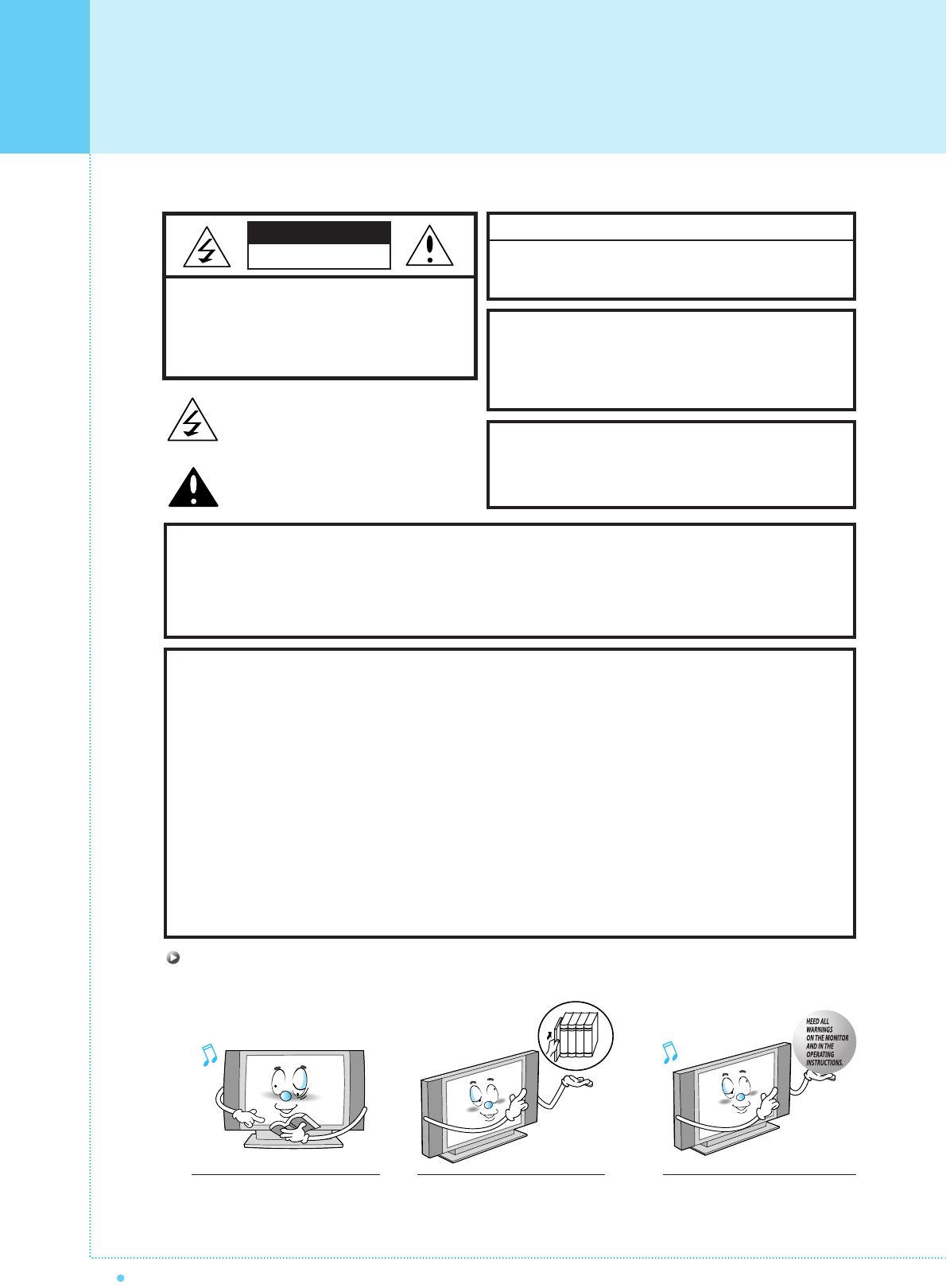
Read all safety and operating
instructions before operating
your Monitor.
Keep the safety and operating
instructions for future reference.
Heed all warnings on the Monitor
and in the operating instructions.
CAUTION : TO REDUCE THE RISK OF
ELECTRIC SHOCK, DO NOT
REMOVE COVER (OR BACK),
NO USER-SERVICEABLE PARTS
INSIDE. REFER SERVICING TO
QUALIFIED SERVICE PERSONNEL.
This symbol is intended to alert the user to the
presence of uninsulated "dangerous voltage"
within the product’s enclosure that may be of
sufficient magnitude to constitute a risk of
electric shock to persons.
This symbol is intended to alert the user to
the presence of important operating and
maintenance(servicing) instructions in the
literature accompanying the appliance.
CAUTION
RISK OF ELECTRIC SHOCK
DO NOT OPEN

Important Safety Information
3
OWNER'S MANUAL
Always be careful when using your PDP. To reduce the risk of fire, electrical shock, and other injuries,
keep these safety precautions in mind when installing, using, and maintaining your machine.
1. Read these instructions.
2. Keep these instructions.
3. Heed all warnings.
4. Follow all instructions.
5. Do not use this apparatus near water.
6. Clean only with a dry cloth.
7. Do not block any of the ventilation openings. Install in accordance with the manufacturer's instructions.
8. Do not install near any heat sources such as radiators, heat registers, stoves, or other apparatus
(including amplifiers) that produce heat.
9. Do not defeat the safety purpose of the polarized or grounding type plug. A polarized plug has two blades with
one wider than the other. A grounding type plug has two blades and a third grounding prong. The wide blade
or the third prong is provided for your safety. When the provided plug does not fit into your outlet, consult an
electrician for replacement of the obsolete outlet.
10. Protect the power cord from bong walked on or pinched particularly at plugs, convenience receptacles, and
the point where they exit from the apparatus.
11. Only use the attachments/accessories specified by the manufacturer.
12. Use only with a cart, stand, tripod, bracket, or table specified by the manufacturer, or sold with the apparatus.
When a cart is used, use caution when moving the cart/apparatus combination to avoid injury from tip-over.
13. Unplug this apparatus during lightning storms or when unused for long periods of time.
14. Refer all servicing to qualified service personnel. Servicing is required when the apparatus has been damaged in
any way, such as power supply cord or plug is damaged, liquid has been spilled or objects have fallen into the
apparatus, the apparatus has been exposed to rain or moisture, does not operate normally, or has been dropped.
4
Important Safety Information
OWNER'S MANUAL
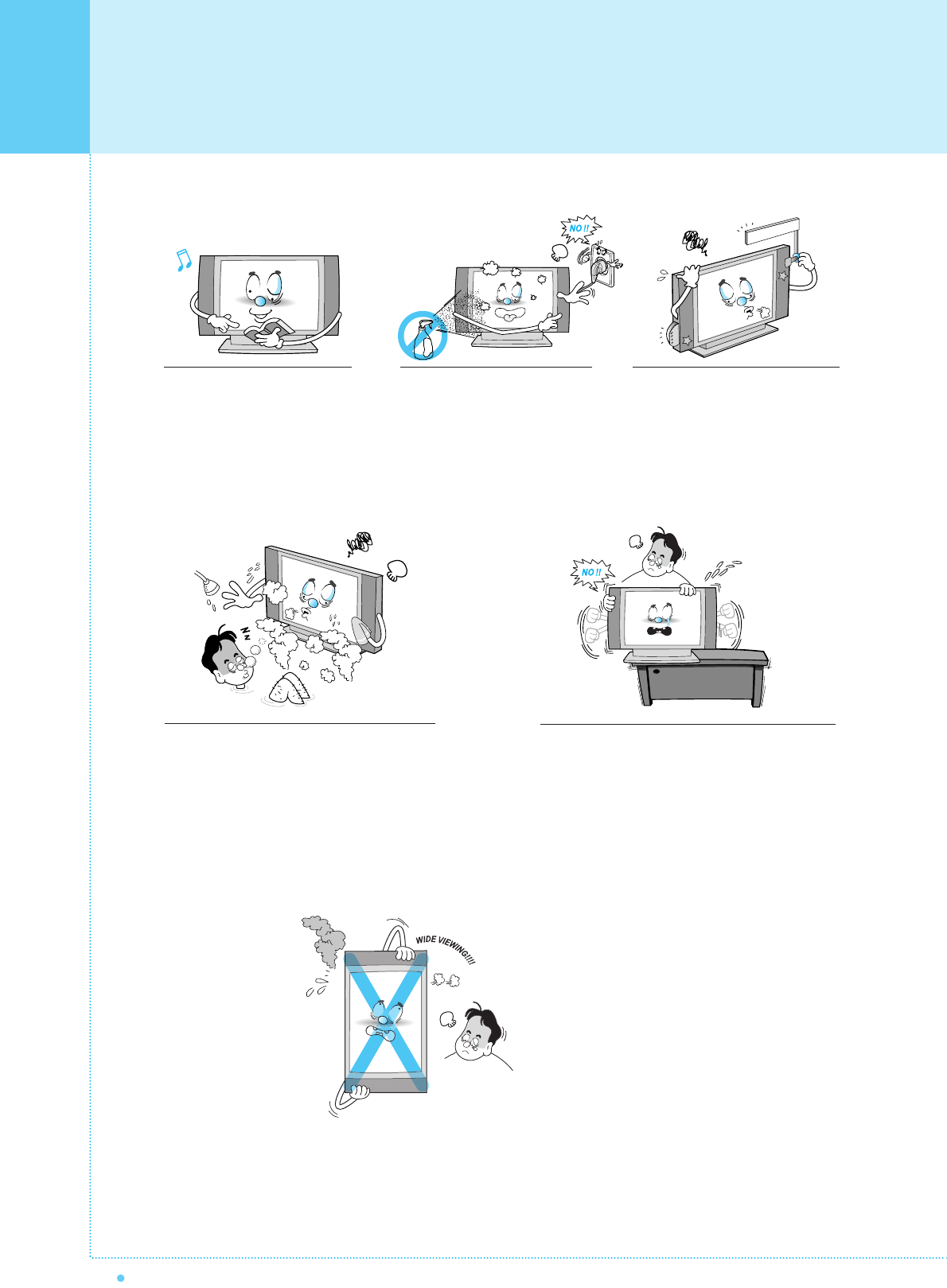
Follow all operating and use
instructions.
Do not use the Monitor where contact with or
immersion in water is a possibility, such as
near bath tubs, sinks, washing machines,
swimming pools, etc.
This plasma display
is designed to be
mounted horizontally
(wide viewing).
Any inquiry regarding
its vertical position
should be forwarded to
the manufacture
directly.
When installing the Monitor on a table, be careful
not to place the edge of its stand.
- This may cause the Monitor to fall, causing serious
injury to a child or adult, and serious damage to the
Monitor.
Unplug the Monitor from the
wall outlet before cleaning. Use
a damp cloth; do not use liquid
or aerosol cleaners.
Never add any attachments and/or
equipment without approval of the
manufacturer. Such additions can
increase the risk of fire, electric
shock, or other personal injury.
Important Safety Information
5
OWNER'S MANUAL
Provide ventilation for the Monitor. The unit is designed
with slots in the cabinet for ventilation to protect it from
overheating. Do not block these openings with any object,
and do not place the Monitor on a bed, sofa, rug or other
similar surface. Do not place it near a radiator or heat
register. If you place the Monitor on a rack or bookcase,
ensure that there is adequate ventilation and that you've
followed the manufacturer's instructions for mounting.
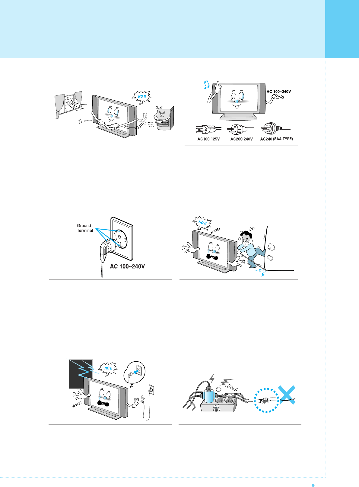
Use only the accessory cord designed for this product
to prevent shock. The power supply voltage rating of
this product is AC100-240V, the power cord attached
conforms to the following power supply voltage. Use
only the power cord designated by our dealer to ensure
Safety and EMC.
When it is used by other power supply voltage, power
cable must be changed. Consult your product dealer.
Use only a grounded or polarized outlet. For your safety,
this Monitor is equipped with a polarized alternating
current line plug having one blade wider than the other.
This plug will fit into the power outlet only one way. If you
are unable to insert the plug fully into the outlet, try
reversing the plug. If the plug still does not fit, contact
your electrician to replace your outlet.
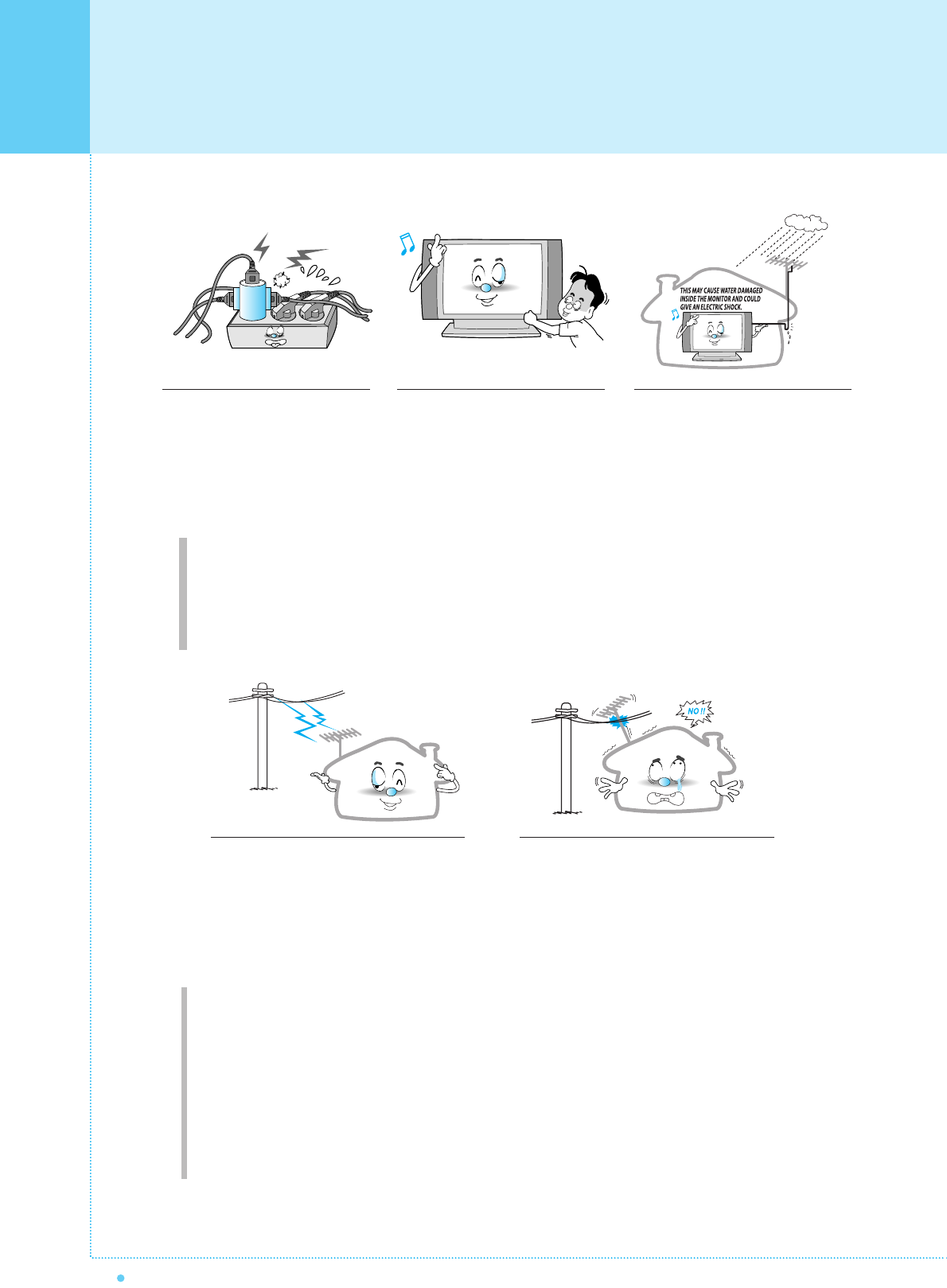
Avoid overhead power lines. An outside antenna
system should not be placed in the vicinity of
overhead power lines or other electric light or power
circuits or where it can fall into such power lines or
circuits. When installing an outside antenna system,
be extremely careful to keep from touching the
power lines or circuits. Contact with such lines can
be fatal.
Unplug the Monitor from the wall outlet and disconnect
the antenna or cable system during a lightning storm
or when left unattended and unused for long periods
of time. This will prevent damage to the unit due to
lightning and power-line surges.
Protect the power cord. Power supply cords should be
routed so that they won't be walked on or pinched by
objects placed on or against them. Pay particular attention
to cords at plugs, convenience receptacles, and the point
where they exit from the unit.
Important Safety Information
6OWNER'S MANUAL
Ground outdoor antennas. If an outside antenna or cable system is connected to the Monitor, be sure the
antenna or cable system is grounded so as to provide some protection against voltage surges and built-up
static charges. Section 810 of the National Electrical Code, ANSI/NFPA No.70-1984, provides information about
proper grounding of the mast and supporting structure, grounding of the lead-in wire to an antenna discharge
unit, size of grounding conductors, location of antenna discharge unit, connection to grounding electrodes, and
requirements for the grounding electrode.
Do not overload the wall outlet or
extension cords. Overloading can
result in fire or electric shock.
Do not insert anything through the
openings in the unit, where they
can touch dangerous voltage points
or damage parts. Never spill liquid
of any kind on the Monitor.
Bend antenna cable between inside
and outside building to prevent rain
from flowing in.
- This may cause water damaged inside
the Monitor and could give an electric
shock.
Do not place an outside antenna in the
vicinity of overhead power lines or other
electric light or power circuits.
- This may cause an electric shock.
There should be enough distance between
an outside antenna and power lines to keep
the former from touching the latter even
when the antenna falls.
- This may cause an electric shock.
Do not attempt to service the Monitor yourself. Refer all servicing to qualified service
personnel. Unplug the unit from the wall outlet and refer servicing to qualified service
personnel under the following conditions:
• when the power-supply cord or plug is damaged
• if liquid has been spilled on the unit or if objects have fallen into the unit
• if the Monitor has been exposed to rain or water
• if the Monitor does not operate normally by following the operating instructions
• if the Monitor has been dropped or the cabinet has been damaged
• when the Monitor exhibits a distinct change in performance

Important Safety Information
7
OWNER'S MANUAL
When replacement parts are
required, be sure the service
technician uses replacement parts
specified by the manufacturer or
those that have the same
characteristics as the original part.
Unauthorized substitutions may
result in additional damage to the
unit.
Upon completion of any service or
repairs to this Monitor, ask the
service technician to perform safety
checks to determine that the
Monitor is in a safe operating
condition.
If you make adjustments yourself,
adjust only those controls that are
covered by the operating instructions.
Adjusting other controls may result in
damage and will often require
extensive work by a qualified
technician to restore the Monitor to
normal.
Only use the specified batteries.
- This make cause damaged the
Monitor or could give an electric
shock.
Do not place anything containing
liquid on top of the Monitor.
- This may cause a fire or could give an
electric shock.
In case of smoke or strange smell
from the Monitor, switch it off, unplug
it from the wall outlet and contact
your dealer or service center.
- This may cause a fire or could give an
electric shock.
The distance between eyes and
the screen should be about 5~7
times as long as diagonal length
of the screen.
- If not, eyes will strain.
When moving the Monitor
assembled with speakers do not
carry holding the speakers.
- This may cause the Monitor to fall,
causing serious injury to a child or
adult, and serious damage to the
Monitor.
Avoid having a fixed image remain
on the screen for a long period of
time. Typically a frozen still picture
from a VCR, 4:3 picture format or
if a CH label is present; the fixed
image may remain visible on the
screen.
8OWNER'S MANUAL
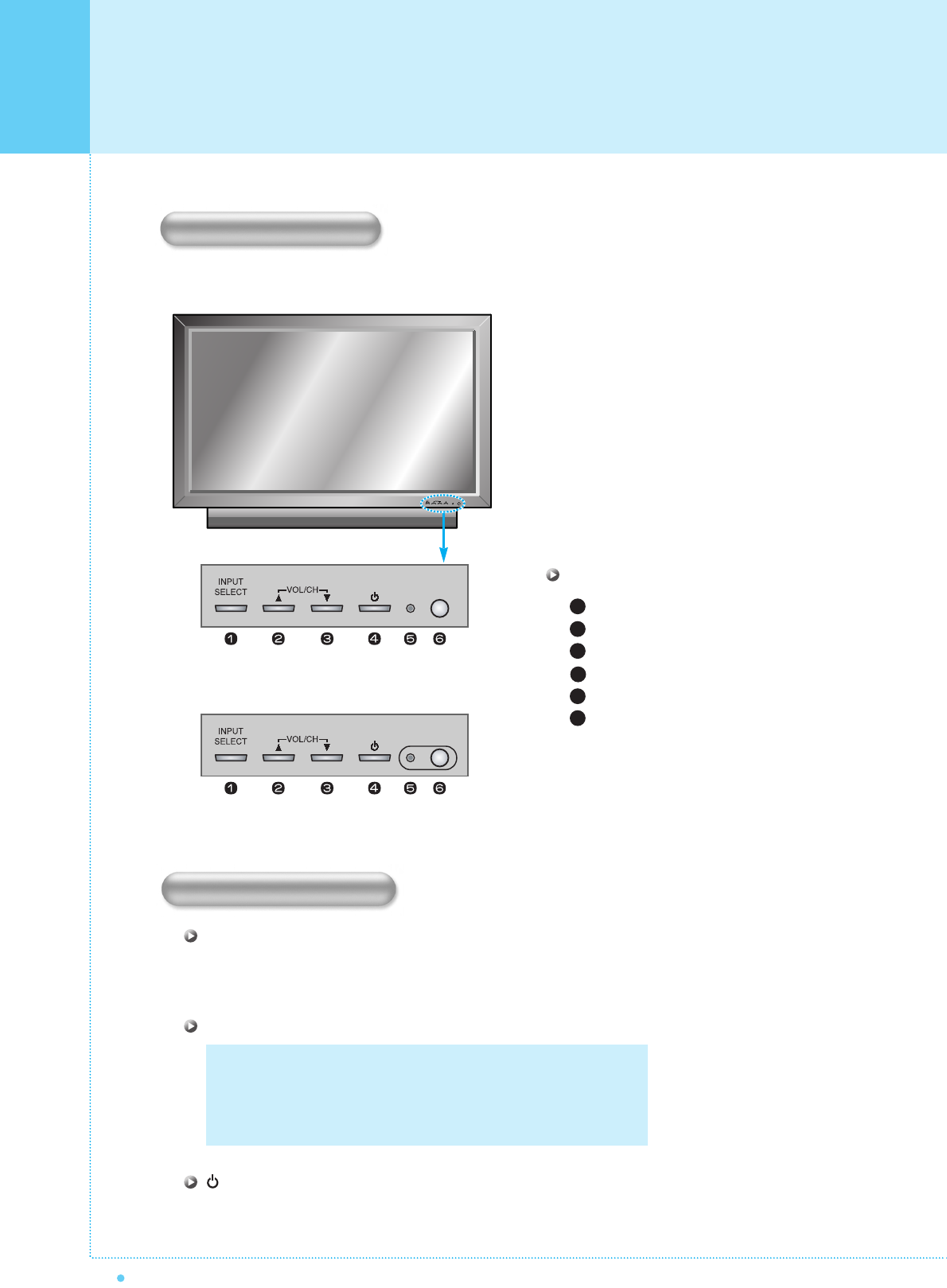
Select the signal source from multiple input sources such as TV, AV 1, AV 2, S-Video / AV, Component1,
Component2, PC and DVI.
To change the CHANNEL,
Press
button first and change the CHANNEL with
,
buttons.
To change the VOLUME,
Press
button first and change the VOLUME with
,
buttons.
Turn the PDP on and off.
Front Panel
< D Type >
< I Type >
Input Source Select
UP
DOWN (See the box below.)
Power (Stand By)
Status / Power Indicator LED
Remote Sensor
1
2
3
4
5
6
OSD Key Position
OSD key & Function
INPUT SELECT
VOL/CH
Power On /Off
OSD Key Function
Overview Of Your New PDP
9
OWNER'S MANUAL
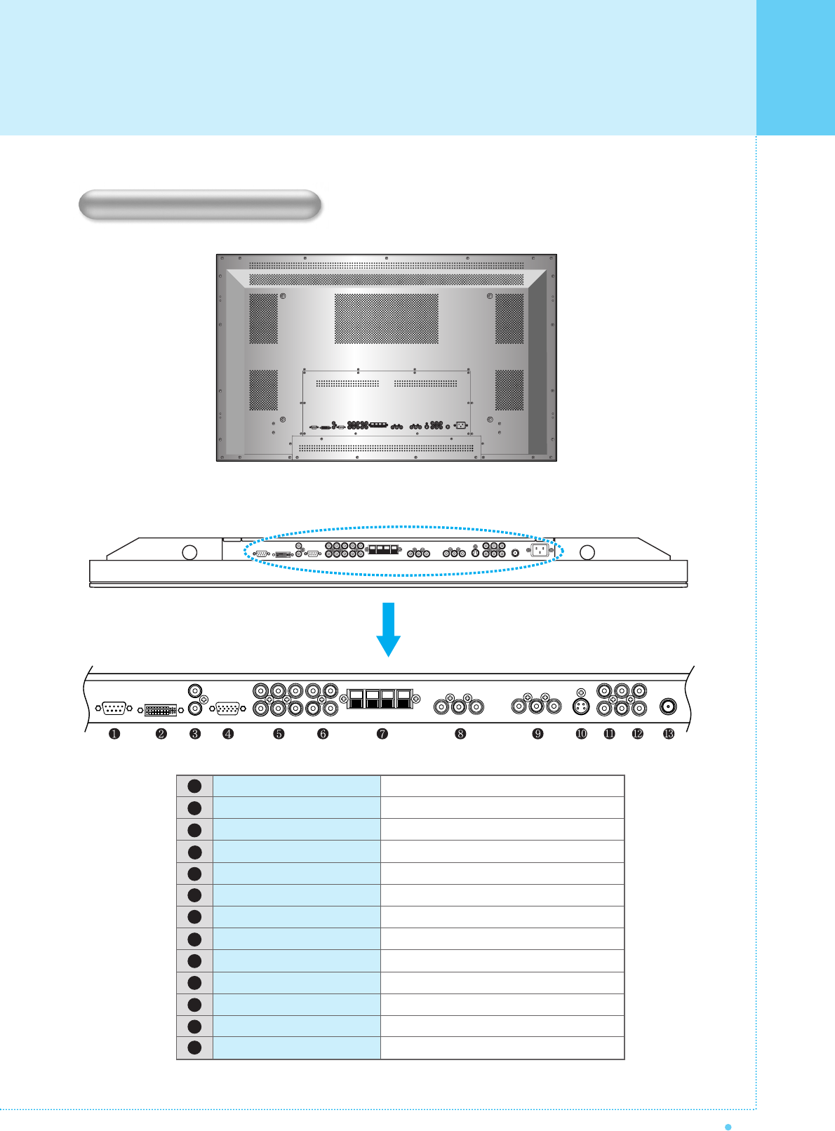
To control from PC.
For PC, Set top box.
PC/DVI Audio Input.
For PC, Set top box.
For DVD, Set top box.
For Component Audio Input.
To connect speakers (2CH, Stereo)
For VCR, DVD, Set top box.
For VCR, DVD, Set top box.
For DVD, Set top box, S-VHS.
To connect other TV or monitor.
For VCR, DVD, Set top box.
For TV antenna cable. (Air)
RS-232C
DVI
PC Sound
D-Sub (PC)
Component 1, 2
Component Sound
Speakers
AV 1
AV 2
S-Video
AV Output
AV 3
TV Antenna
< Back panel of the monitor >
1
2
3
4
5
6
7
8
9
10
11
12
13
Back Panel and Jacks
Overview Of Your New PDP
10 OWNER'S MANUAL
2
3
5
4
6
7
8
3
2
5
4
6
7
8
PC PDP
3-Wire (Non-standard)
AUDIO INPUT
COMPOSITE VIDEO INPUT
COMPOSITE VIDEO OUTPUT
S-VIDEO INPUT
COMPONENT VIDEO INPUT
ANALOG RGB INPUT
DIGITAL VIDEO INPUT
RCA Pin Jack
RCA Pin Jack
RCA Pin Jack
Mini Din 4 Pin
RCA Pin Jack
Mini D-Sub 15pin
DVI-D 24 pin
• Cables connecting the PC vary according to the
type of machine, so consult your product dealer.
(If the cable is different to the picture, inquire
your PC service center)
1
2
3
4
5
6
7
8 9
11
10
12
13
14
RS-232C Jack
Connects a control signal from a PC.
DVI Input Jack
Connects a digital video signal from a DVI output jack of PC or Set Top box.
PC Sound
Connects a sound signal from PC or DVI.
RGB PC Input Jack ( D-Sub )
Connects a video signal from a video output jack of PC.
Cables connecting the PC vary according to the type of machine, so contact your product dealer.
Component Input Jack 1, 2
Connects a three separate component video signal from a component output jack of a DVD player
or Set Top box.
Supports 480i/60Hz, 480p/60Hz, 576i/50Hz, 576p/50Hz, 720p/60Hz, 720p/50Hz, 1080i/50Hz,
1080i/60Hz signals. (i: interlace, p: progressive)
Component Sound
Connects a sound signal from component.
Speaker Jack
Connects external speakers by wires. Match red/red and black/black of speaker/TV.
Composite (RCA) input Jack 1, 2
Connects an AV composite video signal from a composite output terminal of a VCR or DVD player.
S-Video Input Jack
Connects a S-Video video signals from a S-Video output jack of a S-VHS, VCR or DVD player.
(Upper). Composite (RCA) output Jack
Output the signal of the current screen of the PDP. Connects to other TV or monitor.
(Lower). Composite (RCA) input Jack 3
Connects an AV composite video signal from a composite output terminal of a VCR or DVD player.
Unavailable when a S-Video cable is put into the S-Video input jack.
ANT. IN (TV Antenna Jack)
Connects to an TV antenna cable.
AC(POWER) Input Terminal
Firmly insert the accessory power cord as far as it will go into the power input terminal.
Firmly push the power cord plug as far as it will go into the power socket.
RS-232C Configurations
RXD
TXD
GND
DTR
DSR
RTS
CTS
TXD
RXD
GND
DTR
DSR
RTS
CTS
Overview Of Your New PDP
Connectors
11
OWNER'S MANUAL
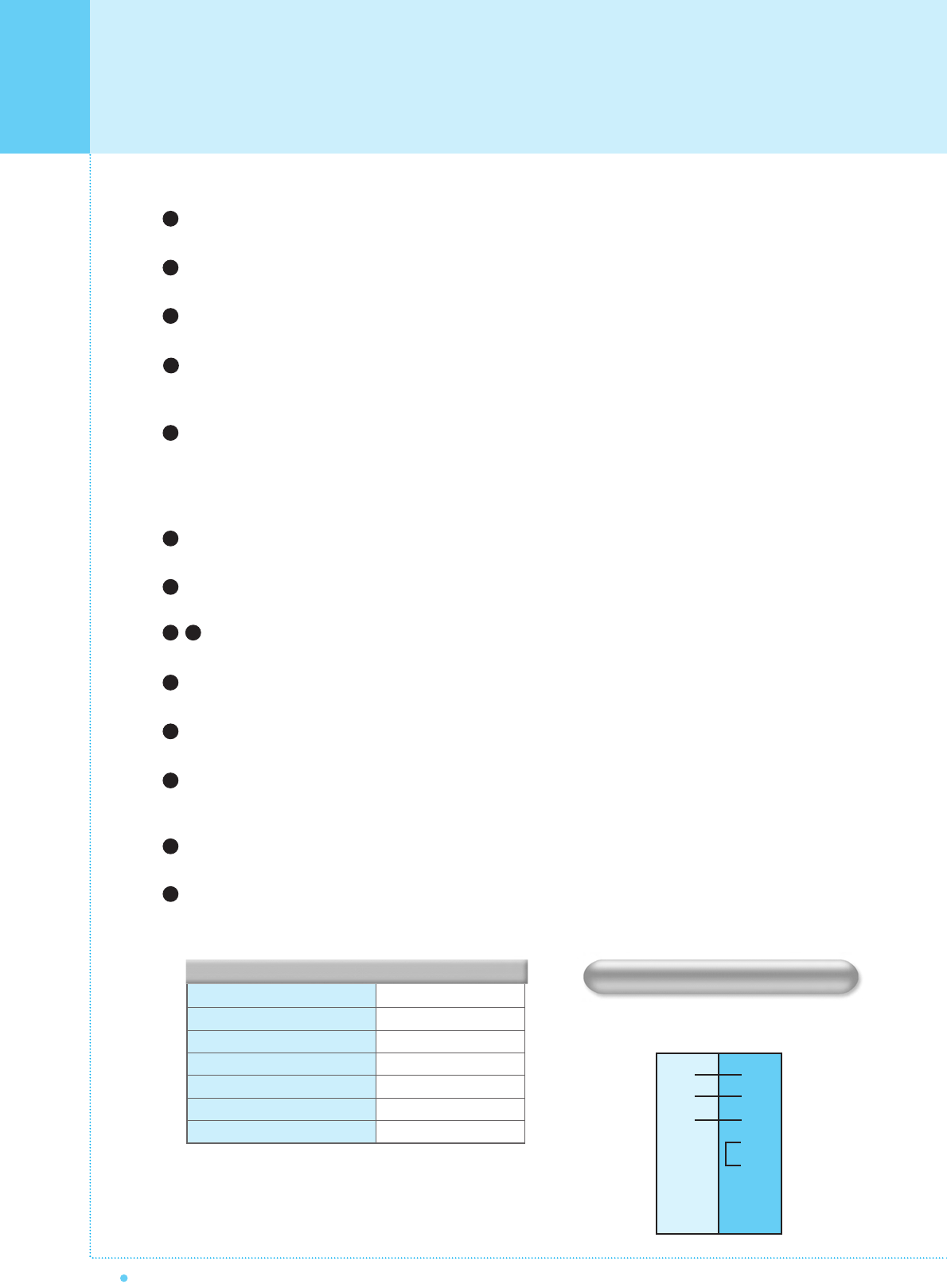
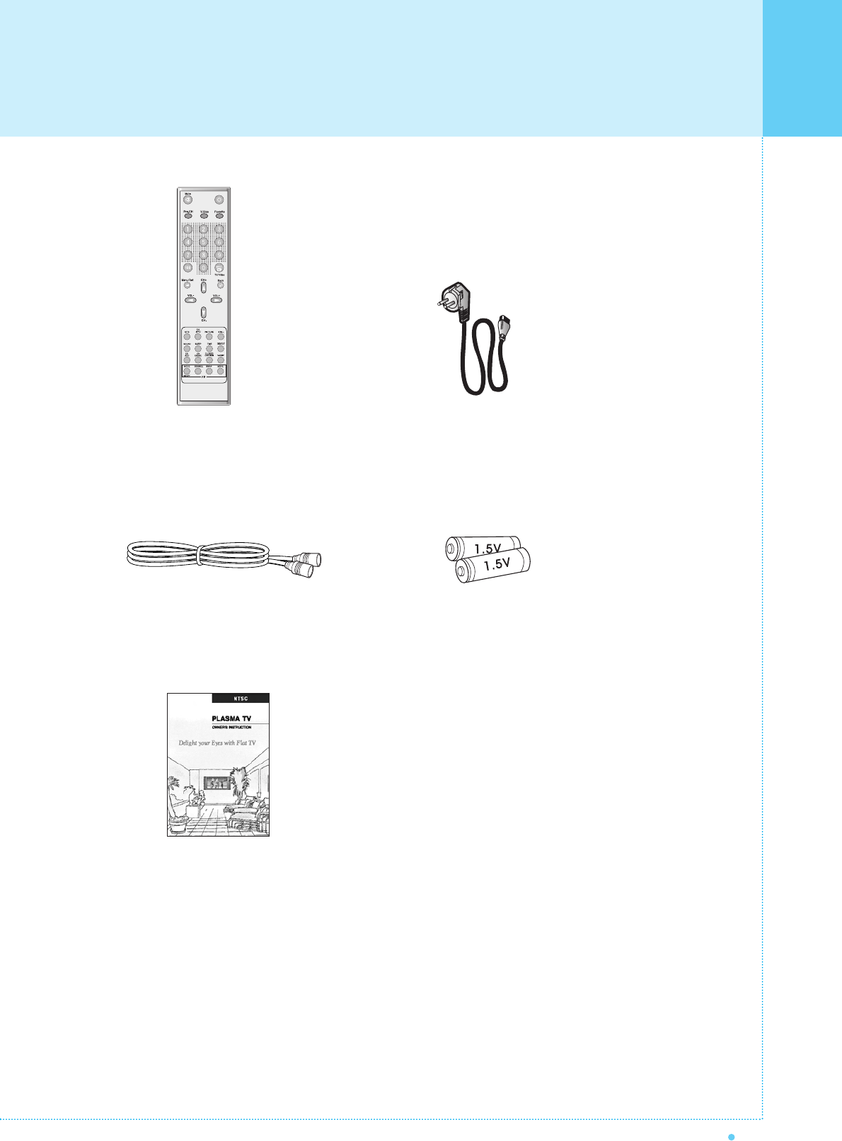
Remote Control Handset Power Cord
RF Cable
Owner's Manual
Alkaline Batteries
Accessories
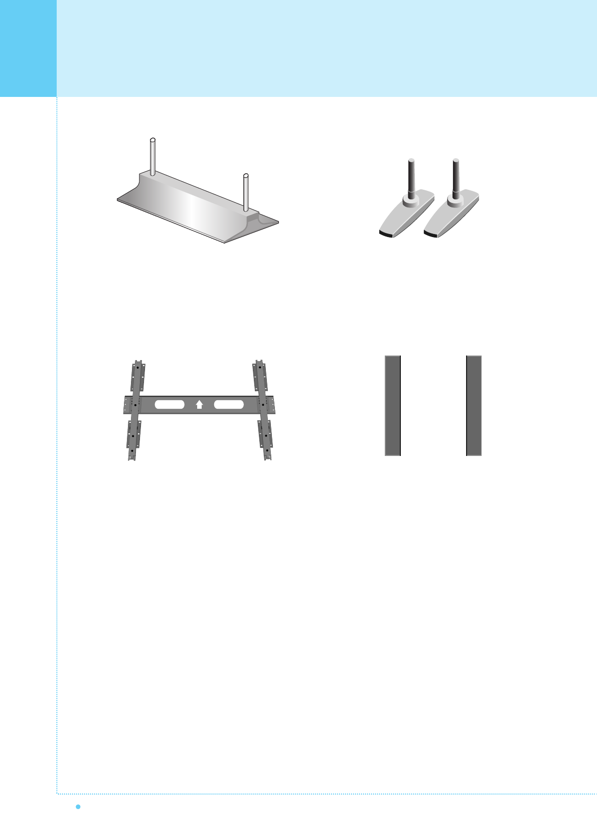
Optional Extras
12 OWNER'S MANUAL
Table Stand
(Type United)
Table Stand
(Type Separated)
Fixed Wall Mount Bracket Side Mount Speaker
13
OWNER'S MANUAL
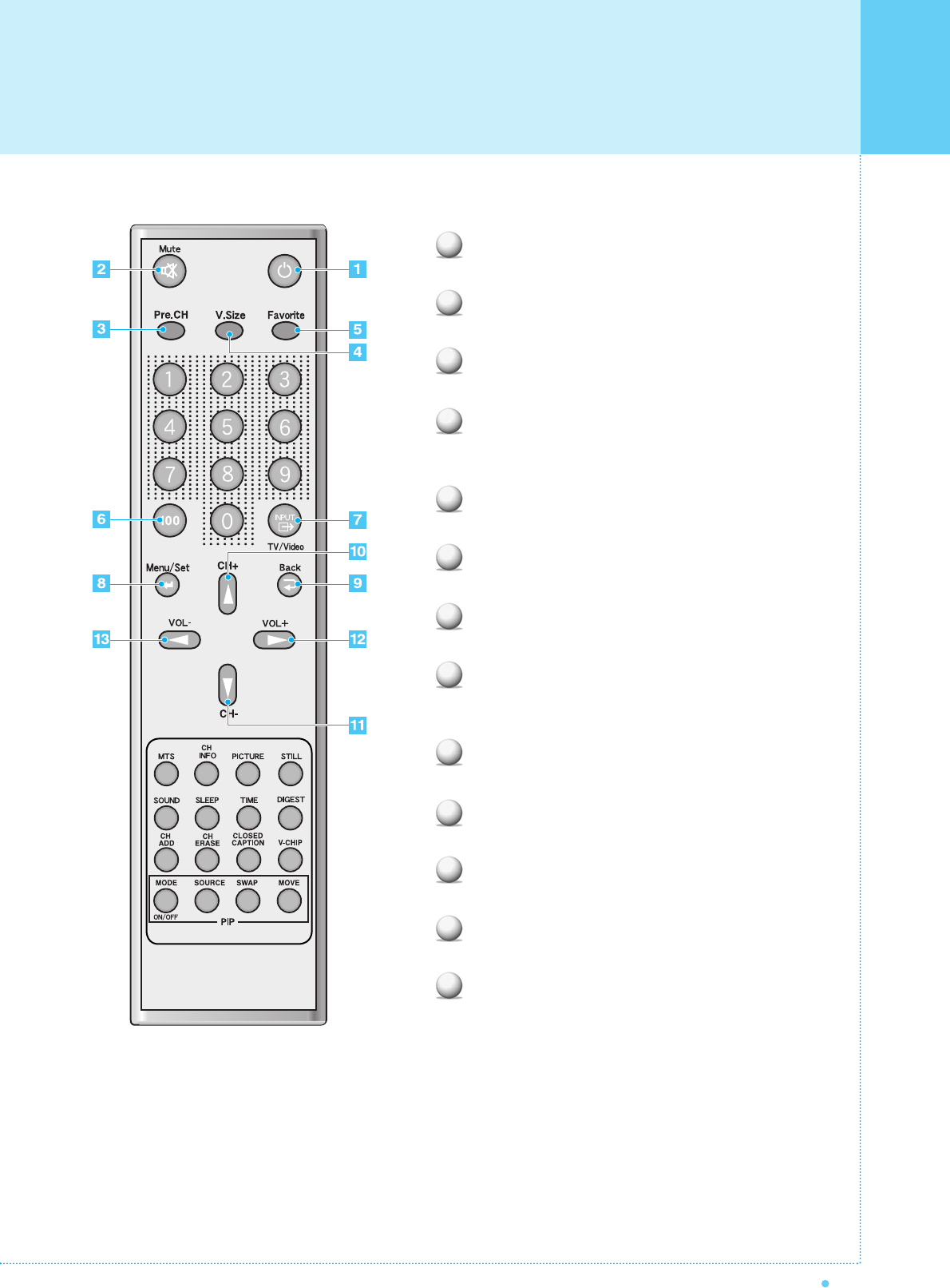
Power
Turn the PDP on and off.
Mute
Temporarily cut the sound and restore it.
Pre.CH
Turn to the previous channel or exit OSD.
V.Size
Choose the Screen Form.
16:9 ➔ Panorama ➔ Zoom1 ➔ Zoom2 ➔ 4:3
FAVORITE (FAVOURITE)
Tune to your next favorite channel.
100
Press to tune the channels over 100.
INPUT
Display the input source list.
Menu / Set
Display the main OSD menu.
Activate your choice in the OSD menu.
Back
Return to the previous OSD menu.
CH+
Move to the upper channel.
CH-
Move to the lower channel.
VOL+
Increase the volume level.
VOL-
Decrease the volume level.
1
2
3
4
5
6
7
8
9
10
11
12
13
Remote Control
Remote Control
14 OWNER'S MANUAL
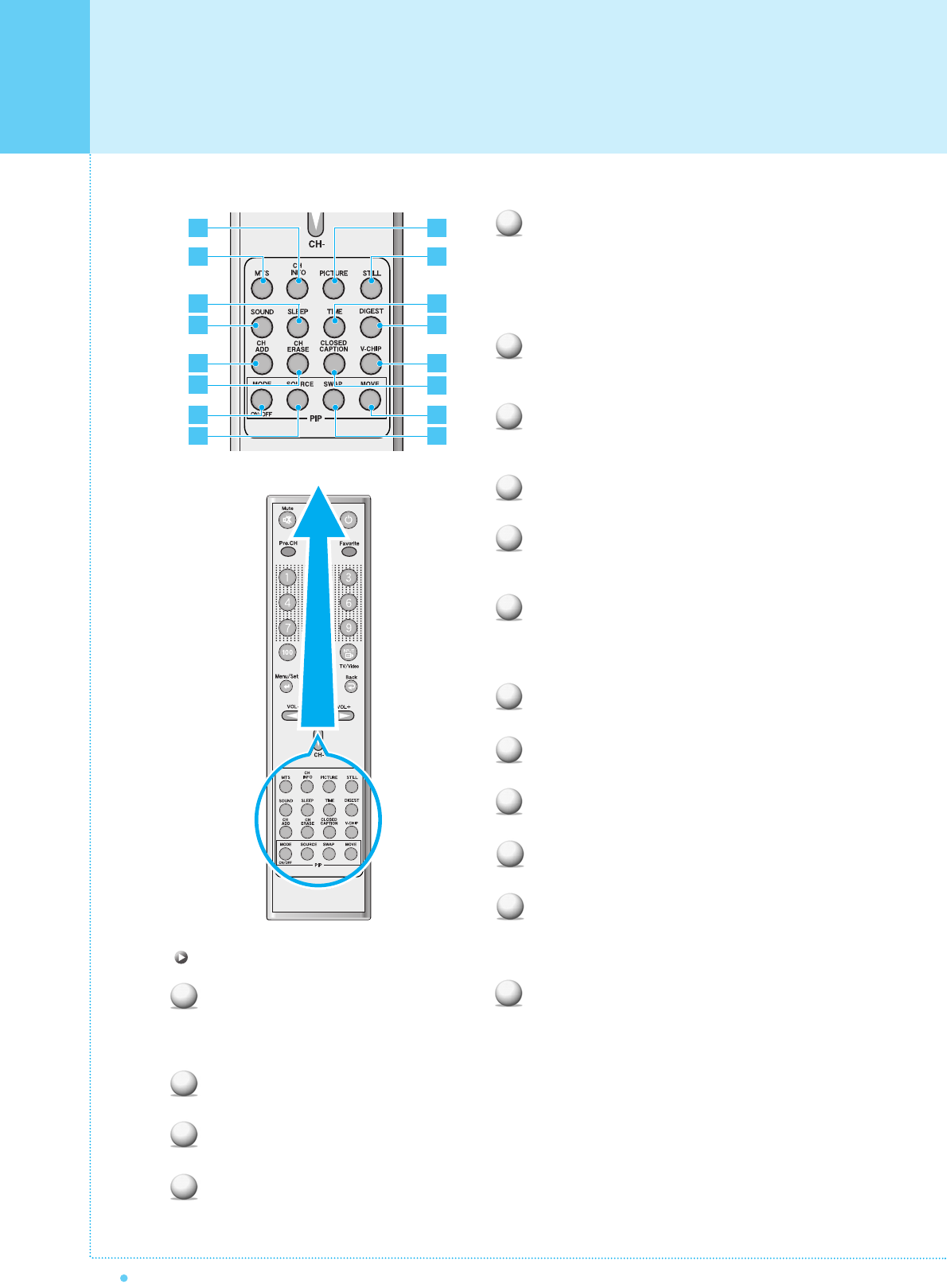
MTS
Choose the MTS (Stereo) mode. Each time it is
pressed, different mode is selected.
Mono ➔ Stereo ➔ SAP
• You can select only available modes depending on
the source.
CH INFO
Display the current information about time, screen
form, source and MTS mode.
PICTURE
There are 4 picture modes.
Standard ➔ Vivid ➔ Mild ➔ User
STILL
Temporarily freeze the screen and restore it.
SOUND
Choose the sound equalizer settings.
Standard ➔ Movie ➔ Music ➔ News ➔ User
SLEEP
Set the preset time interval for automatic turn-off.
OFF(Not Work) ➔ 10 ➔ 20 ➔ 30 ➔ 60 ➔ 90 ➔ 120
➔ 150 ➔ 180
TIME
Display the current time on the screen.
Digest
Display 9 TV programs at the same time.
CH ADD
Add the current channel to memory.
CH ERASE
Erase the current channel from memory.
CLOSE CAPTION
Set the close caption.
OFF ➔ Close Caption1 ➔ Close Caption2 ➔ Text1
➔ Text2
V-CHIP
Get into V-Chip menu.
1
2
3
4
5
6
7
8
9
12
11
10
PIP (Picture In Picture) Keys
MODE (On / Off)
Activate PIP function and change the PIP
window size and PIP mode.
Small ➔ Large ➔ Twin (Half) ➔ OFF
SOURCE
Change the PIP window source.
SWAP
Swap the main screen and the PIP window.
MOVE
Move the position of the PIP window.
2
6
10
4
3
7
1
5
9
8
12
11
16
15
13
14
13
14
15
16
15
OWNER'S MANUAL
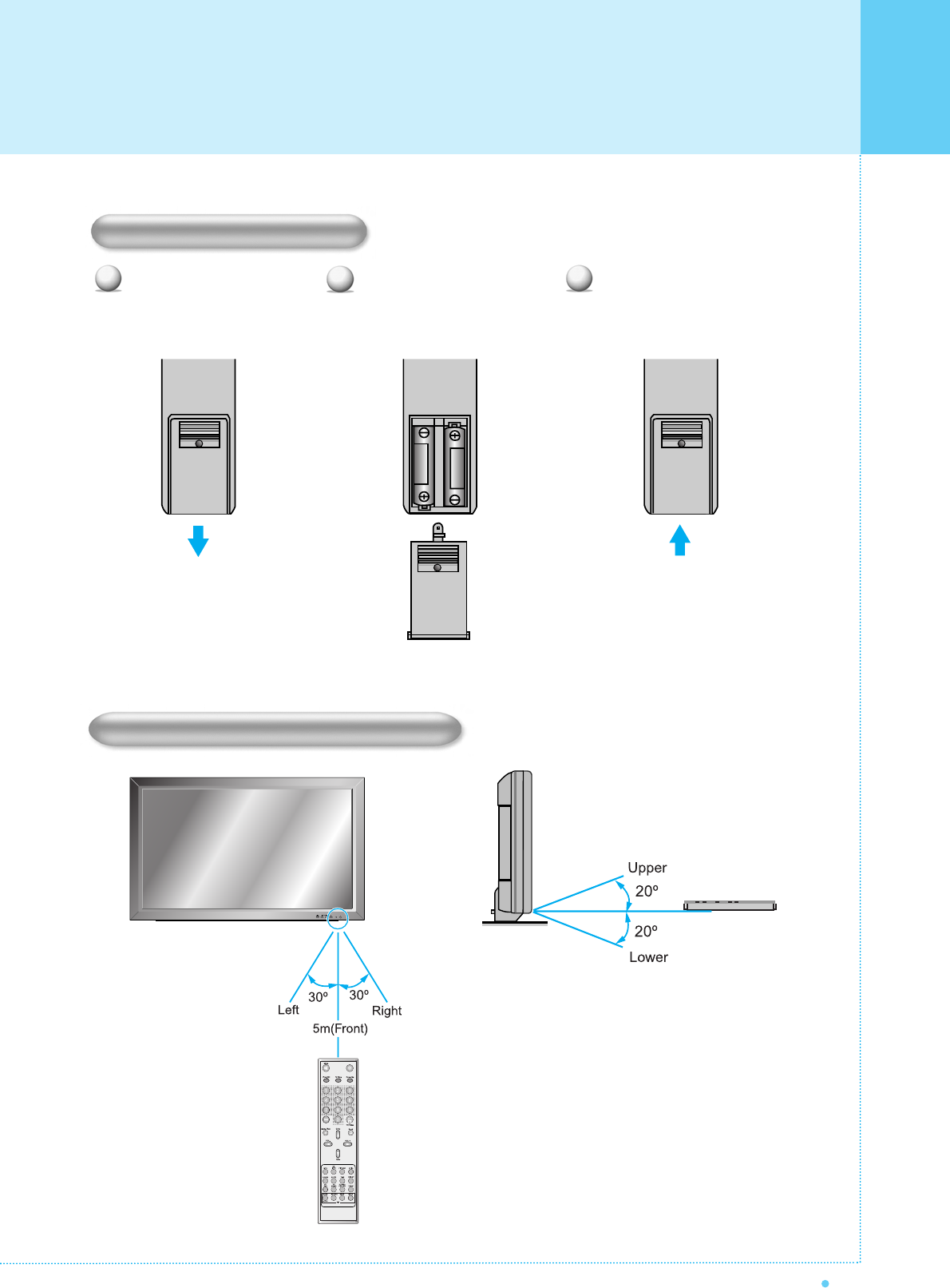
Close the cover until it clicks. Load two AAA batteries, taking
care that the + and - ends face
the correct direction.
Press on the cover and slide
in the direction of the arrow.
123
Loading The Batteries
Reception Range of Remote Control
Remote Control
Monitor Installation
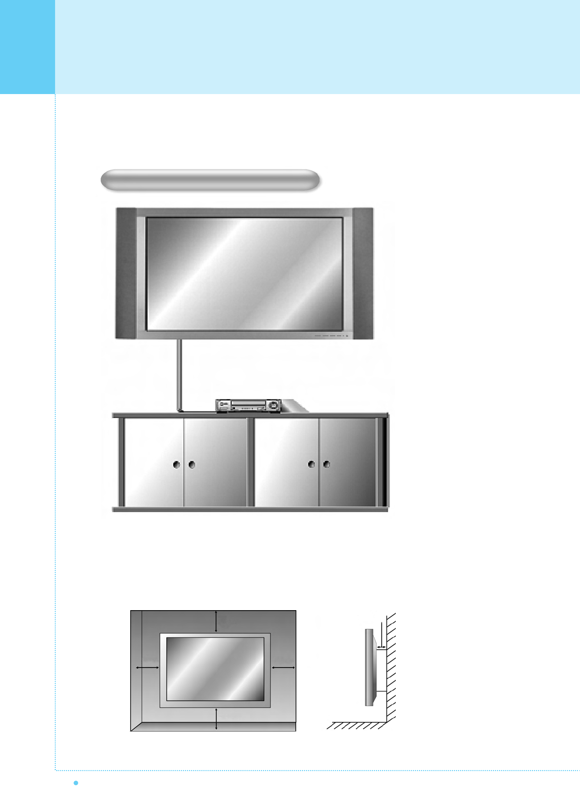
16 OWNER'S MANUAL
< The monitor can be installed on the wall as the picture above >
The Monitor can be installed in various ways such as Wall Mounting type, Table Stand type, etc..
• Install this monitor only in a location where adequate ventilation is available.
Wall Mount Installation (optional)
1.18inch
4inch
4inch
4inch4inch
Monitor Installation
17
OWNER'S MANUAL
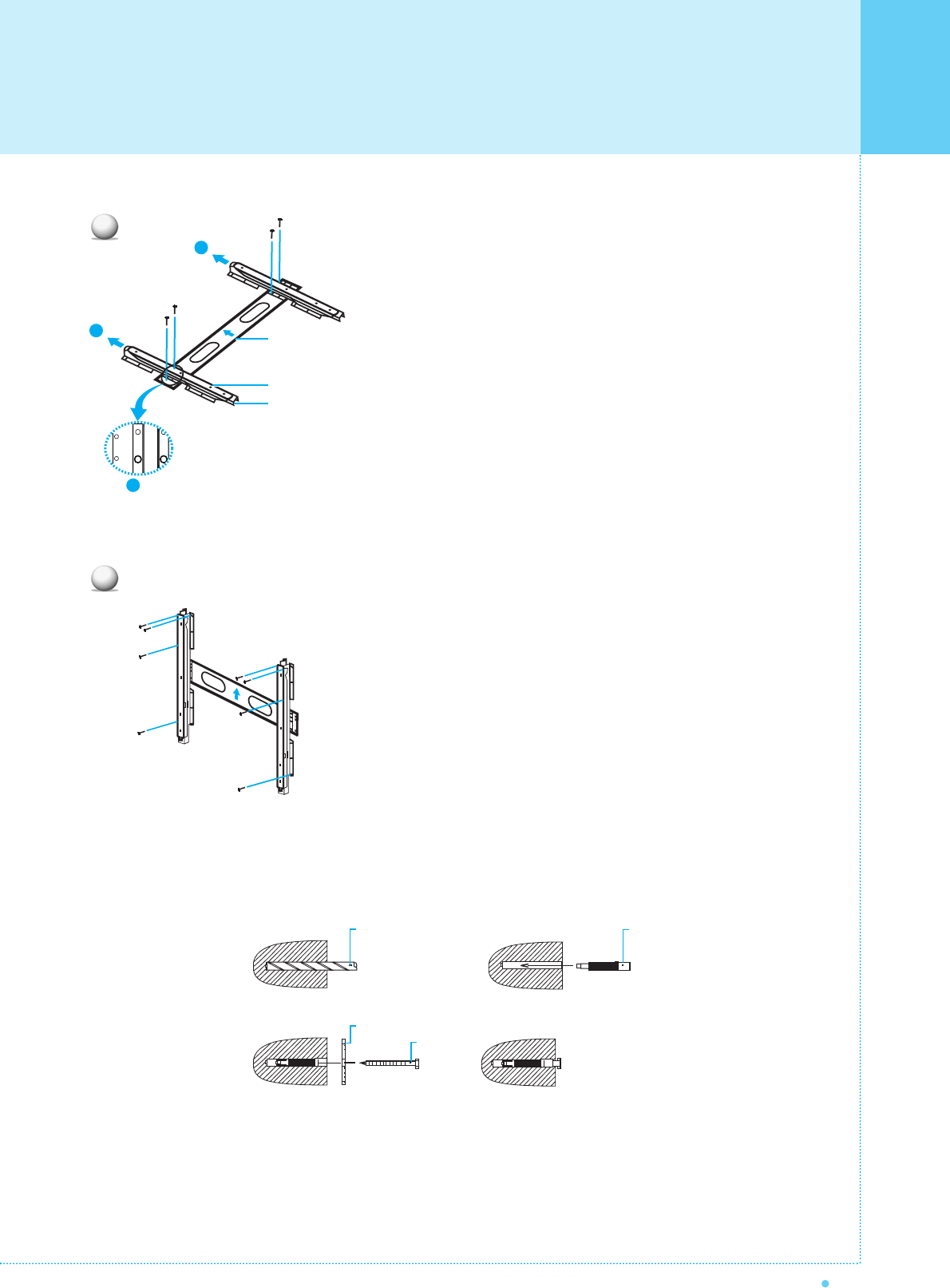
1. Before installation of monitor, Assemble to the same
inch of the PDP shown as left(2).
2. Lift the monitor brackets off the mounting frame shown
as arrow 1.
1. Drill the 8 hole positions shown as left. Using an 8mm
drill appropriate for the material on the wall, drill each
hole to a depth of exceed 80mm.
2. Clean each drill hole.
3. Insert an anchor supplied with the wall mounting bracket
into each hole.
4. Mount the wall mounting bracket on the wall using the 8
screws supplied.
GUIDE BRACKET
MONITOR BRACKET
WALL MOUNTING BRACKET
WALL DRILL(Ø 8mm)
SCREW
ANCHOR
WALL MOUNTING BRACKET
1
2
2
1
1