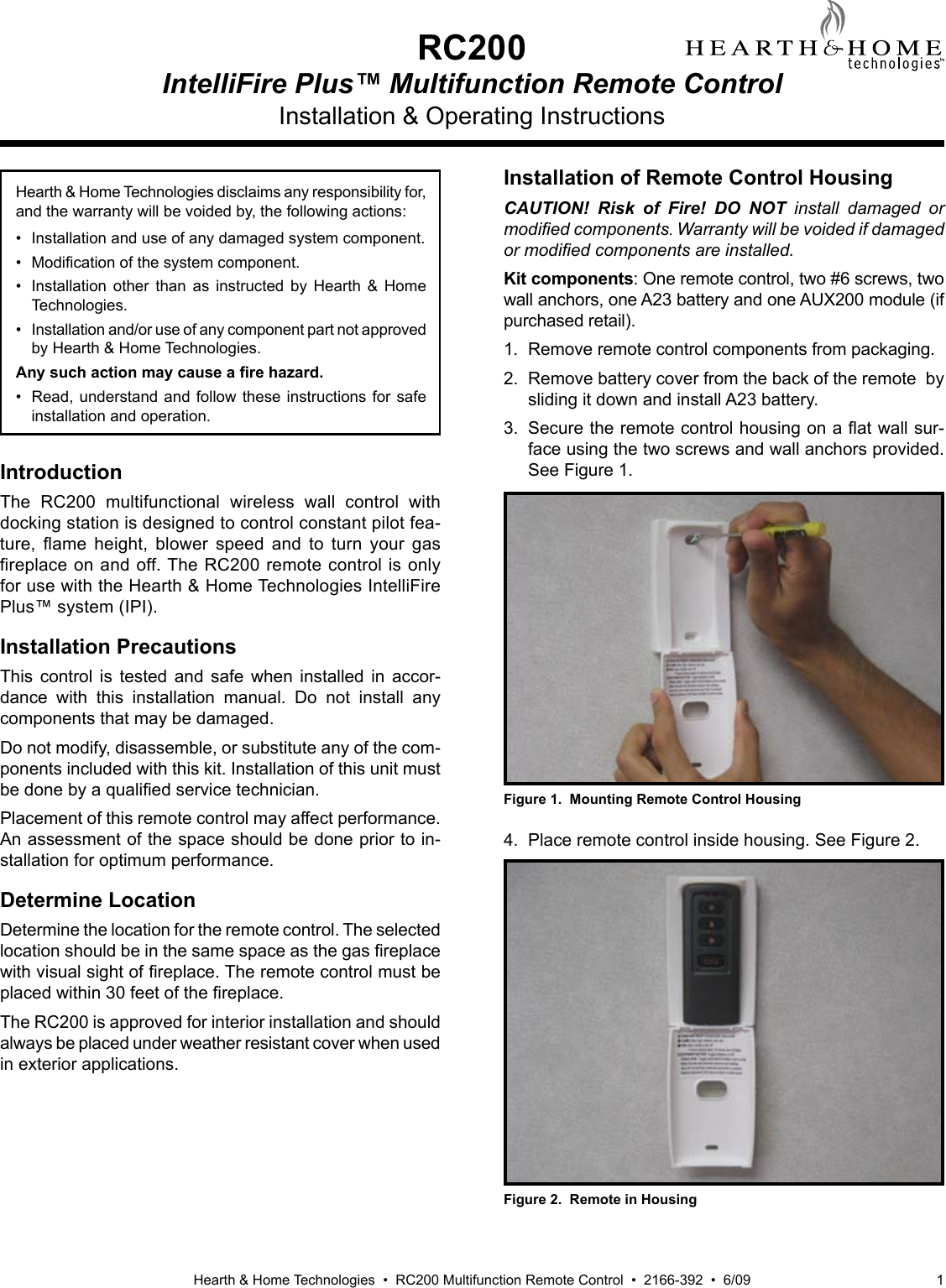
Hearth and Home Technologies RC200 Remote Control Transmitter User Manual

Hearth & Home Technologies Remote Control Transmitter

User manual

Hearth & Home Technologies  •  RC200 Multifunction Remote Control  •  2166-392  •  6/09 1Installation & Operating InstructionsRC200IntelliFire Plus™ Multifunction Remote Control Hearth & Home Technologies disclaims any responsibility for, and the warranty will be voided by, the following actions:•  Installation and use of any damaged system component.• Modicationofthesystemcomponent.•  Installation  other  than  as  instructed  by  Hearth  &  Home Technologies.•  Installation and/or use of any component part not approved by Hearth & Home Technologies.Any such action may cause a re hazard.•  Read, understand and follow these instructions for safe installation and operation.IntroductionThe  RC200  multifunctional  wireless  wall  control  with docking station is designed to control constant pilot fea-ture, ame height, blower speed and to turn your gasreplaceonandoff.TheRC200remotecontrolisonlyfor use with the Hearth & Home Technologies IntelliFire Plus™ system (IPI).Installation PrecautionsThis  control  is  tested  and  safe  when  installed  in  accor-dance  with  this  installation  manual.  Do  not  install  any components that may be damaged. Do not modify, disassemble, or substitute any of the com-ponents included with this kit. Installation of this unit must bedonebyaqualiedservicetechnician.Placement of this remote control may affect performance. An assessment of the space should be done prior to in-stallation for optimum performance.Determine LocationDetermine the location for the remote control. The selected locationshouldbeinthesamespaceasthegasreplacewithvisualsightofreplace.Theremotecontrolmustbeplacedwithin30feetofthereplace.The RC200 is approved for interior installation and should always be placed under weather resistant cover when used in exterior applications.Installation of Remote Control HousingCAUTION!  Risk  of  Fire!  DO  NOT  install  damaged  or modied components. Warranty will be voided if damaged or modied components are installed.Kit components: One remote control, two #6 screws, two wall anchors, one A23 battery and one AUX200 module (if purchased retail).1.  Remove remote control components from packaging.2.  Remove battery cover from the back of the remote  by sliding it down and install A23 battery.3.Securetheremotecontrolhousingonaatwallsur-face using the two screws and wall anchors provided. See Figure 1.Figure 1.  Mounting Remote Control Housing4.  Place remote control inside housing. See Figure 2.Figure 2.  Remote in Housing
Hearth & Home Technologies  •  RC200 Multifunction Remote Control  •  2166-392  •  6/092Figure 3.  Mounting Remote Control Housing5.  Close the housing door and press the power button. The red light illuminates if the batteries were properly installed.  See Figure 3.Figure 6.  Programming RC200REMOTE POSITIONFan Installation•  Insert the 3 prong plug from the fan into the receptacle located in the AUX200 module.  See Figure 5.•  Insert 3 prong plug from AUX200 module into REM/AUX receptacleofreplacejunctionbox.Figure 5.  Plug Fan into AUX200 ModuleFigure 4.  AUX 200 module installationProgramming the RC200 to the Control ModuleCAUTION! Risk of burns! DO NOT program the remote control to the control module when replace is hot.•  Verify the ON/OFF/REMOTE switch is in the REMOTE position. Control module will beep twice when ready. See Figure 6.•  Using a  small  item  (such  as  a  paper  clip)  press  and release  the  learn  button  located  near  the  ON/OFF/REMOTE switch.  See Figure 6.•  Control module will beep once and LED will blink green for 10 seconds. •  While  the  LED  is  blinking,  press  the  power  button  on the remote control.  A double beep will come out of the control module to indicate that it has been programmed successfully.NOTICE: Up to three remote controls can be programmed into the control module. Simply press a button on the other remote controls during the 10 second programming process to add another remote into the system.To clear memory in the control module, use a small item (such  as  a  paper  clip)  to  press  and  release  the  LEARN button. Control module will beep once and LED will blink green for 10 seconds  DO NOT press any buttons on the remote during the ten seconds that the green LED blinks. The memory will be cleared.RED LEDAUX200CABLEFAN CORDAUX200 Module Installation•  Control Module should be set in the OFF position before any components are installed.•  Insert the 4 hole harness from the AUX200 module into the 4 pin plug on the control module.  See Figure 4.
Hearth & Home Technologies  •  RC200 Multifunction Remote Control  •  2166-392  •  6/09 3TO JUNCTION BOX (120V)CONTROL MODULEISFLAMESENSEWHITEWHITEORANGEIGNITER3 PRONG 120VACRC200 12V DC(A23 X 1)TO JUNCTION BOX 120VACGROUNDORANGE(PILOT)GREEN(MAIN)BROWNBLACKREDBROWN/REDOPTIONAL ON/OFF SWITCHBATTERY PACK6V DC (AA X 4)FLAMEMODULATIONAUX200 MODULEFAN6V DC SUPPLYFigure 8.  RC200 Wiring DiagramPress the PILOT button to activate or deactivate the constant pilot. The control module will beep once  indicating constant pilot has been activat-ed.  A  double beep indicates  the  constant  pilot has been deactivated.Press the FLAME button to adjust the ameheight. Theameheightcan beadjustedto5different settings: MAX, HIGH, MEDIUM, LOW, MIN.Flameheightwillnotbeadjustableforrstten seconds when replace is turned on. Thesystemremembersthepreviousameheightsetting and will automatically adjust to previ-ous setting after 10 seconds.PresstheFANbuttontoadjustthefanspeed.The FAN speedcanbeadjustedto4 different settings: HIGH, MED, LOW and OFF. The fan has a timer built into the control module.  After thereplaceisturnedONthetimerwillwaitfor7 minutes before turning on the fan.  In addition, the fan will remain on for 12 minutes after the replacehasbeenturnedOFF.Wheneverthefan is turned ON, the FAN will  start up on the highsettingfor10secondsbeforeadjustingtothe previous user setting.MenuSelect VVMenuSelect VVMenuSelect VVFunction ButtonsMenuSelect VVPressthePOWERbuttontoturnthereplaceONandOFF.Thereplacewillrstignitethepi-lot.Oncethepilotameisestablishedthemainburner will be lit. Setting the Child Lock•  Remove battery cover from the back of the remote  by sliding it down. Slide the child lock switch to enable or disable the child lock feature.  See Figure 7.NOTICE: No functions will be usable until child lock feature is disabled.Figure 7.  Child Lock SwitchNOTICE:  Whenever the replace  is cycled from OFF to ON, the main burner will light on high for 10 seconds before returning to the previous user setting.
Hearth & Home Technologies  •  RC200 Multifunction Remote Control  •  2166-392  •  6/094Frequently Asked Questions/TroubleshootingPlease contact your Hearth & Home Technologies dealer with any questions or concerns. For the location of your nearest Hearth & Home Technologies dealer, pleasevisitwww.reside.com.Power Outage• IfreplacebatterybackupsystemISinstalledattimeofpoweroutage,replaceoperationwillnotbeinterrupted.• IfreplacebatterybackupsystemISNOTinstalledattimeofpoweroutage,replacewillshutoff.Toresumereplaceoperation,installbatterybackup.Symptom Possible Cause Corrective ActionRemote control will not transmitBatteries Verify battery is functional and installed correctly.Remote control is in Child Lock mode Disengage Child Lock mode.Control module will not take commands from remote controlControl module is in “REMOTE” mode Ensure module switch is set to REMOTE.Control module and remote control are not programmed to each otherThe  control  module  will  beep  when  it  successfully  re-ceives  a  command.    If  it  does  not  beep,  clear  module memory and reprogram wall switch.Control module is unplugged. In case of power outage, backup batteries are depleted or missingIf red LED light comes on when power button is pressed, verifythatthecontrolmoduleispluggedinthereplacejunctionboxlocatedinthecontrolsarea.Alsoverifythatthe batteries are installed in the battery pack.Fan does not turn on when replaceisstarted Built in time delay Thereplacemustrunforsevenminutesinorderforthefan to engage.Fan does not turn off when replaceturnedoff Built in time delay Thefanwillrunfortwelveminutesafterthereplaceisturned off.Fireplace shuts down after extended periods Built-in timer The replace will automatically shut down after ninehours of continuous operation in REMOTE mode.  Fireplace is on but will not shut off with the remote controlExternal wired wall switchThereplacecannotbeturnedoffbyremoteifanexter-nal wired wall switch is installed and in the ON position.  Turn external wall switch to OFF.Control module failureAt control module, turn off replace by sliding the ON/OFF/REMOTE  switch  to  OFF.  Warning!  Risk  of  Fire! Fireplace is hot. Use caution when accessing module.WARNING! Risk of burns! In the event of a wall switch malfunction,  DO  NOT  attempt  to  turn  off  the  replace manually using the control module. The decorative front will be hot and severe burns may occur. Call you dealer for assistance.Operation  is  subject  to  the  following  two  conditions:  (1)  this  device  may  not  cause  interference,  and   (2)  this  device  must  accept  any  interference,  including  interference  that       may  cause  undesired  operation  of  the  deviceYou  are  cautioned  that  changes  or  modifications  not  expressly  approved  by  the  party  responsible  for  compliance  could  void  your  authority  to  operate  the  equipment.

Navigation menu