Hearth and Home Technologies RC200 Remote Control Transmitter User Manual
Hearth & Home Technologies Remote Control Transmitter
User manual
Hearth & Home Technologies • RC200 Multifunction Remote Control • 2166-392 • 6/09 1
Installation & Operating Instructions
RC200
IntelliFire Plus™ Multifunction Remote Control
Hearth & Home Technologies disclaims any responsibility for,
and the warranty will be voided by, the following actions:
• Installation and use of any damaged system component.
• Modicationofthesystemcomponent.
• Installation other than as instructed by Hearth & Home
Technologies.
• Installation and/or use of any component part not approved
by Hearth & Home Technologies.
Any such action may cause a re hazard.
• Read, understand and follow these instructions for safe
installation and operation.
Introduction
The RC200 multifunctional wireless wall control with
docking station is designed to control constant pilot fea-
ture, ame height, blower speed and to turn your gas
replaceonandoff.TheRC200remotecontrolisonly
for use with the Hearth & Home Technologies IntelliFire
Plus™ system (IPI).
Installation Precautions
This control is tested and safe when installed in accor-
dance with this installation manual. Do not install any
components that may be damaged.
Do not modify, disassemble, or substitute any of the com-
ponents included with this kit. Installation of this unit must
bedonebyaqualiedservicetechnician.
Placement of this remote control may affect performance.
An assessment of the space should be done prior to in-
stallation for optimum performance.
Determine Location
Determine the location for the remote control. The selected
locationshouldbeinthesamespaceasthegasreplace
withvisualsightofreplace.Theremotecontrolmustbe
placedwithin30feetofthereplace.
The RC200 is approved for interior installation and should
always be placed under weather resistant cover when used
in exterior applications.
Installation of Remote Control Housing
CAUTION! Risk of Fire! DO NOT install damaged or
modied components. Warranty will be voided if damaged
or modied components are installed.
Kit components: One remote control, two #6 screws, two
wall anchors, one A23 battery and one AUX200 module (if
purchased retail).
1. Remove remote control components from packaging.
2. Remove battery cover from the back of the remote by
sliding it down and install A23 battery.
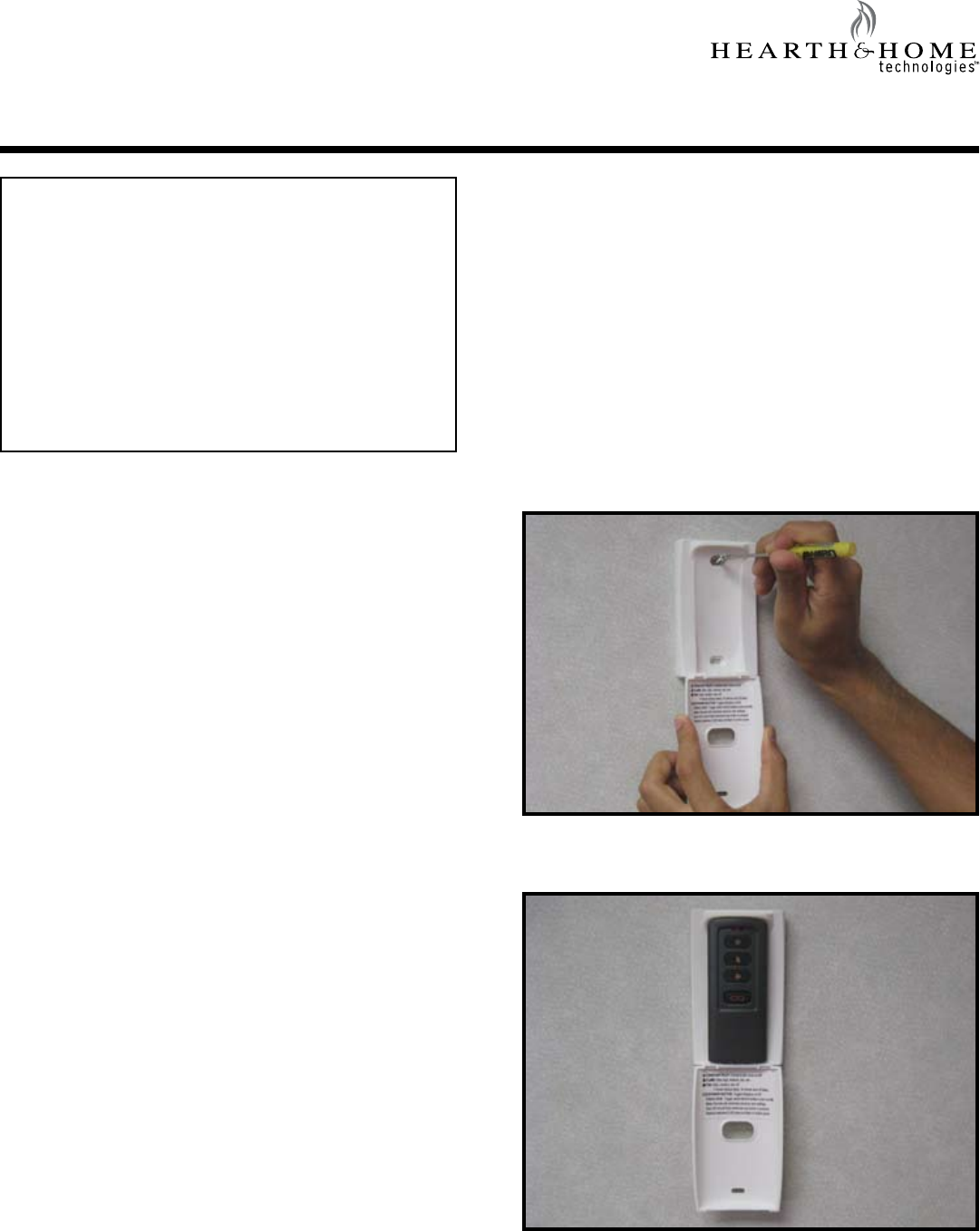
3.Securetheremotecontrolhousingonaatwallsur-
face using the two screws and wall anchors provided.
See Figure 1.
Figure 1. Mounting Remote Control Housing
4. Place remote control inside housing. See Figure 2.
Figure 2. Remote in Housing
Hearth & Home Technologies • RC200 Multifunction Remote Control • 2166-392 • 6/09
2
Figure 3. Mounting Remote Control Housing
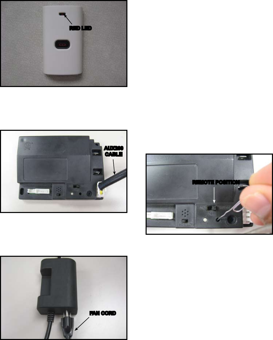
5. Close the housing door and press the power button.
The red light illuminates if the batteries were properly
installed. See Figure 3.
Figure 6. Programming RC200
REMOTE POSITION
Fan Installation
• Insert the 3 prong plug from the fan into the receptacle
located in the AUX200 module. See Figure 5.
• Insert 3 prong plug from AUX200 module into REM/AUX
receptacleofreplacejunctionbox.
Figure 5. Plug Fan into AUX200 Module
Figure 4. AUX 200 module installation
Programming the RC200 to the Control Module
CAUTION! Risk of burns! DO NOT program the remote
control to the control module when replace is hot.
• Verify the ON/OFF/REMOTE switch is in the REMOTE
position. Control module will beep twice when ready.
See Figure 6.
• Using a small item (such as a paper clip) press and
release the learn button located near the ON/OFF/
REMOTE switch. See Figure 6.
• Control module will beep once and LED will blink green
for 10 seconds.
• While the LED is blinking, press the power button on
the remote control. A double beep will come out of the
control module to indicate that it has been programmed
successfully.
NOTICE: Up to three remote controls can be programmed
into the control module. Simply press a button on the other
remote controls during the 10 second programming process
to add another remote into the system.
To clear memory in the control module, use a small item
(such as a paper clip) to press and release the LEARN
button. Control module will beep once and LED will blink
green for 10 seconds DO NOT press any buttons on the
remote during the ten seconds that the green LED blinks.
The memory will be cleared.
RED LED
AUX200
CABLE
FAN CORD
AUX200 Module Installation
• Control Module should be set in the OFF position before
any components are installed.
• Insert the 4 hole harness from the AUX200 module into
the 4 pin plug on the control module. See Figure 4.
Hearth & Home Technologies • RC200 Multifunction Remote Control • 2166-392 • 6/09 3
TO JUNCTION
BOX (120V)
CONTROL MODULE
I
S
FLAME
SENSE
WHITE
WHITE
ORANGE
IGNITER
3 PRONG 120VAC
RC200 12V DC
(A23 X 1)
TO JUNCTION
BOX 120VAC
GROUND
ORANGE
(PILOT)
GREEN
(MAIN)
BROWN
BLACK
RED
BROWN/RED
OPTIONAL ON/OFF
SWITCH
BATTERY PACK
6V DC (AA X 4)
FLAME
MODULATION
AUX200 MODULE
FAN
6V DC
SUPPLY
Figure 8. RC200 Wiring Diagram
Press the PILOT button to activate or deactivate
the constant pilot. The control module will beep
once indicating constant pilot has been activat-
ed. A double beep indicates the constant pilot
has been deactivated.
Press the FLAME button to adjust the ame
height. Theameheightcan beadjustedto5
different settings: MAX, HIGH, MEDIUM, LOW,
MIN.Flameheightwillnotbeadjustableforrst
ten seconds when replace is turned on. The
systemremembersthepreviousameheight
setting and will automatically adjust to previ-
ous setting after 10 seconds.
PresstheFANbuttontoadjustthefanspeed.
The FAN speedcanbeadjustedto4 different
settings: HIGH, MED, LOW and OFF. The fan
has a timer built into the control module. After
thereplaceisturnedONthetimerwillwaitfor
7 minutes before turning on the fan. In addition,
the fan will remain on for 12 minutes after the
replacehasbeenturnedOFF.Wheneverthe
fan is turned ON, the FAN will start up on the
highsettingfor10secondsbeforeadjustingto
the previous user setting.
Menu
Select V
V
Menu
Select V
V
Menu
Select V
V
Function Buttons
Menu
Select V
V
PressthePOWERbuttontoturnthereplace
ONandOFF.Thereplacewillrstignitethepi-
lot.Oncethepilotameisestablishedthemain
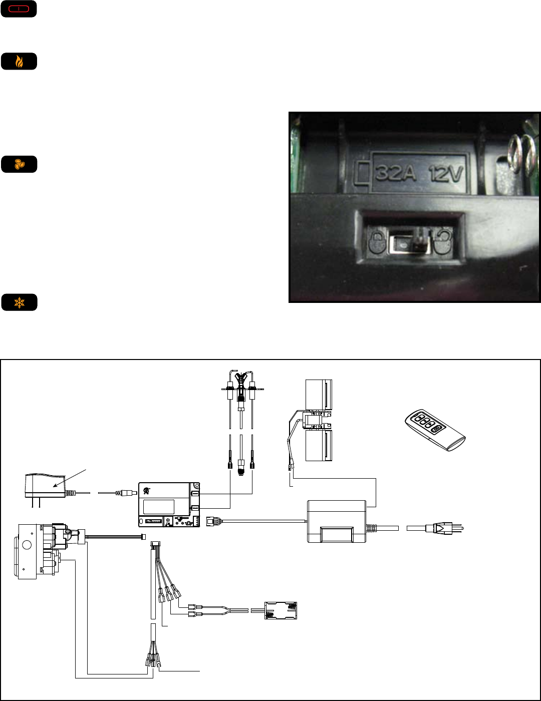
burner will be lit. Setting the Child Lock
• Remove battery cover from the back of the remote by
sliding it down. Slide the child lock switch to enable or
disable the child lock feature. See Figure 7.
NOTICE: No functions will be usable until child lock feature
is disabled.
Figure 7. Child Lock Switch
NOTICE: Whenever the replace is cycled from OFF to
ON, the main burner will light on high for 10 seconds before
returning to the previous user setting.

Hearth & Home Technologies • RC200 Multifunction Remote Control • 2166-392 • 6/09
4
Frequently Asked Questions/Troubleshooting
Please contact your Hearth & Home Technologies
dealer with any questions or concerns.
For the location of your nearest
Hearth & Home Technologies dealer,
pleasevisitwww.reside.com.
Power Outage
• IfreplacebatterybackupsystemISinstalledattimeof
poweroutage,replaceoperationwillnotbeinterrupted.
• IfreplacebatterybackupsystemISNOTinstalledat
timeofpoweroutage,replacewillshutoff.Toresume
replaceoperation,installbatterybackup.
Symptom Possible Cause Corrective Action
Remote control will not transmit
Batteries Verify battery is functional and installed correctly.
Remote control is in
Child Lock mode Disengage Child Lock mode.
Control module will not take
commands from remote control
Control module is in
“REMOTE” mode Ensure module switch is set to REMOTE.
Control module and
remote control are not
programmed to each
other
The control module will beep when it successfully re-
ceives a command. If it does not beep, clear module
memory and reprogram wall switch.
Control module is
unplugged. In case of
power outage, backup
batteries are depleted or
missing
If red LED light comes on when power button is pressed,
verifythatthecontrolmoduleispluggedinthereplace
junctionboxlocatedinthecontrolsarea.Alsoverifythat
the batteries are installed in the battery pack.
Fan does not turn on when
replaceisstarted Built in time delay Thereplacemustrunforsevenminutesinorderforthe
fan to engage.
Fan does not turn off when
replaceturnedoff Built in time delay Thefanwillrunfortwelveminutesafterthereplaceis
turned off.
Fireplace shuts down after
extended periods Built-in timer The replace will automatically shut down after nine
hours of continuous operation in REMOTE mode.
Fireplace is on but will not shut off
with the remote control
External wired wall
switch
Thereplacecannotbeturnedoffbyremoteifanexter-
nal wired wall switch is installed and in the ON position.
Turn external wall switch to OFF.
Control module failure
At control module, turn off replace by sliding the ON/
OFF/REMOTE switch to OFF. Warning! Risk of Fire!
Fireplace is hot. Use caution when accessing module.
WARNING! Risk of burns! In the event of a wall switch
malfunction, DO NOT attempt to turn off the replace
manually using the control module. The decorative front
will be hot and severe burns may occur. Call you dealer
for assistance.
Operation is subject to the following two conditions:
(1) this device may not cause interference, and
(2) this device must accept any interference, including interference that
may cause undesired operation of the device
You are cautioned that changes or modifications not expressly approved by
the party responsible for compliance could void your authority to operate the
equipment.