Hisense Broand Multimedia Technologies 001 Gigabit-Capable Passive Optical Network Single Family Unit User Manual
Hisense Broadband Multimedia Technologies Co.,Ltd Gigabit-Capable Passive Optical Network Single Family Unit User Manual
R66001_User manual_Rev1
Page 6
Page 5
7258G
7257G
WLAN
WIFI function is not active.
WIFI function is active.
ETH1-4
Management channel (OMCI) not active.
Management channel (OMCI) active.
POTS
MGMT
ON Ethernet link is operational.
Flashing Indicates data transmission / reception.
OFF No Ethernet link or port is not equipped.
ON Line is off hook (call active or in process).
Flashing Slow Indicates ringing line.
OFF Line is on hook (no call in process) or port is
not equipped.
Flashing Fast Software upgrade has failed.
OFF Optical signal is present and operating nor-
mally.
ON
OFF
ON
Flashing Indicates data transmission / reception.
OFF
Functions Select
Model List
Model
7259G 2POTS + 4GE + CATV + Return + WiFi
2POTS + 4GE + CATV +
Return
2POTS + 4GE + CATV + WiFi
7253G 2POTS + 4GE + CATV
7281G 2POTS + 4GE + WiFi
7251G 2POTS + 4GE
Indoor Type
This device complies with part 15 of the FCC Rules.
Operation is subject to the following two conditions:
(1) This device may not cause harmful interference,
and (2) this device must accept any interference
received, including interference that may cause
undesired operation.
This equipment has been tested and found to comply
with the limits for a Class B digital device, pursuant to
part 15 of the FCC Rules. These limits are designed to
provide reasonable protection against harmful inter-
ference in a residential installation. This equipment
generates, uses and can radiate radio frequency energy,
and if not installed and used in accordance with the
instructions, may cause harmful interference to radio
communications. However, there is no guarantee that
interference will not occur in a particular installation.
If this equipment does cause harmful interference to
radio or television reception, which can be determined
by turning the equipment OFF and ON, the user is
encouraged to try to correct the interference by one or
more of the following measures:
Reorient or relocate the receiving antenna.
Increase the separation between the equipment and
receiver.
Connect the equipment to an outlet on a circuit dif-
ferent from that to which the receiver is connected.
Consult the dealer or an experienced radio/TV
technician for help.
The manufacturer is not responsible for any radio or
TV interference caused by unauthorized modifications
to this equipment. Such modifications could void the
user’s authority to operate the equipment.
FCC RF Safety Caution Statement
To satisfy FCC RF exposure requirement for mobile
and base station transmission devices, a separation
distance of 20cm or more should be maintained
between the antenna of this device and persons during
operation. To ensure compliance, operation at closer
than this distance is not recommended. The antenna(s)
used for this transmitter must not be co-located or
operating in conjunction with any other antenna or
transmitter.
Environmental Requirements
Rated Voltage: DC 12V
Rated Current: 2A
Operating Temperature: +5°C to +40°C
Operating Relative Humidity: 5% to 85%
Storage Temperature: -40°C to +60°C
Storage Relative Humidity: 0% to 95%
FCC Notice -2
The 72xxG North America edition is limited using
channel 1-11. This limited operation can be only set by
software and was done before the product down from the
product line. All the products for North America
marketing were embedded this limited before shipping.
Customers have no way to choose the channel 12 & 13.
FCC Notice -1
The 72xx SFU residential ONT delivers high quality
Please adopt UL certificated UPSNOTICE:
which meets Limited Power Source standard.
Pins for the connector are Molex 46235-5002
OVERVIEW
VoIP voice service, Ethernet data service for high-
speed internet access and IPTV broadcast video plus
– 2 POTS ports - provide voice telephone service
– 4 LAN ports - provide Ethernet connectivity
– WIFI ports - provide WIFI connectivity
INSTALLATION
The 72xx SFU ONT can be mounted vertically or hor-
izontally on any flat surface.
Unpack
Unpack the unit and verify that it is free from shipping
damage.:
Desk Mount
1.) Set the unit on a flat surface considering the follo-
wing:
– within reach of the power source
– no thermal obstructions
–
not in direct sunlight
–
user ability to monitor/operate the unit
Wall Mount
1.) Use wall anchors or wood screws (if mounting to
plywood mounted on a wall), spaced 5.125” apart
center to center.
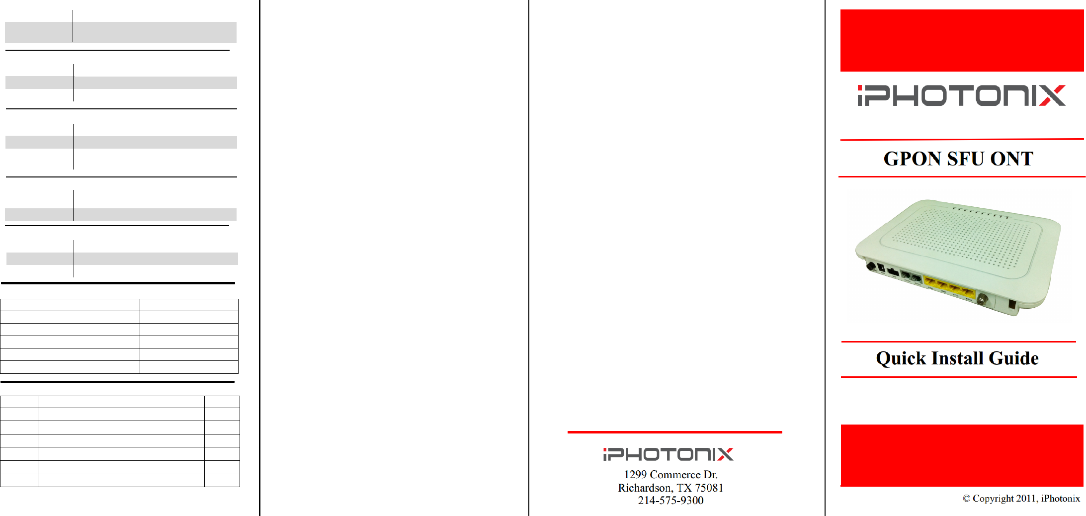
Fiber Connection
1.) On the back left side of the unit is a fiber cover.
Slide the fiber cover off as shown.
Page 1
2.) With the fiber connector exposed, remove the
dust plug, clean the fiber ends and terminate the
SC equipped fiber.
Danger! . Exposure to invisible LASER
radiation may cause serious retinal dam-
age or even blindness. Verify the optical
source is disabled through the use of an optical
power meter before handling optical fibers
.
3.) Insert the fiber into the cover slot and slide the
cover back onto the 72xx unit.
Power
1.) Connect the 2.5mm DC power plug to the
port labeled PWR.
UPS
1.) The UPS alarms are con-
nected via a MOLEX
43025-0800 connector. The
pin orientation as viewed from
the back as shown below.
Page 2
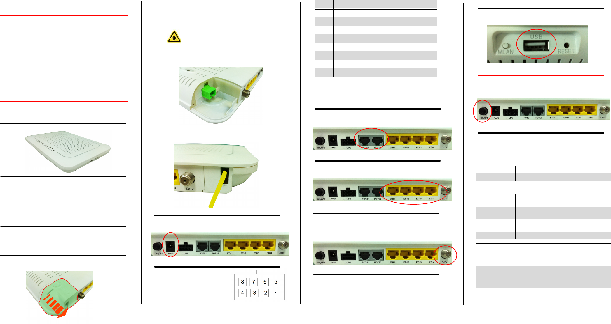
POTS Connections
1.) Connect up to 2 phones to the ports labeled
POTS1 and POTS2 identified below.
LAN Connections
1.) Connect the computers/routers to the ports
labeled ETH1 thru ETH4.
CATV Connections
1.) Connect the television to the port labeled
WIFI Connections
1.) Connect the Notebook computers/WIFI
terminals to the SSID named “iphotonix-
ONT” which can be changed manually.
Page 3
PIN NAME ALM
1 Power Input (+12 VDC) –
2UPS Status: On Battery 1
3 UPS Status: Battery Missing 2
4Signal Return –
5 Power 12V Return –
6UPS Status: Replace Bettery 3
7 UPS Status: Low Battery 4
8No Connection (N/A) –
video on demand services. They provide the follow-
ing user features:(see Model List for exact features)
CATV ports - provide CATV and Return service –
– USB ports - provide data backups service
– UPS ports - provide UPS service
CATV. This port also supports Return se-
rvice in some models.
USB Connections
1.) Connect the flash-disk/portable hard disk to the
port labeled USB on the left side of the units.
USER CONTROLS
The 72xx SFU ONT is equipped with an ON/OFF
button. User functionality should be limited to this
button
LED Descriptions
The 72xx SFU ONT has visual LED indicators to help
the user determine the operational state of the unit. The
LEDs are defined as follows:
Page 4
Power
Battery
FAIL
ON Unit is powered on
OFF Unit is powered off
ON Battery is charged and unit is operating nor-
mally on external power.
Flashing Slow Unit is running off of battery power only.
Check power supply to unit.
Flashing Fast Battery is low and unit may turn off if exter-
nal power is not restored.
OFF Battery is missing or defective.
ON Indicates Loss Of Signal (LOS). No optical
signal is present.
Flashing Slow Margnal signal indicates a weak optical sig-
nal from carrier. Clean fiber connection per
local procatice and check power with an opti-
cal meter.