Hitron TECHNOLOGIES CGN21A 8x4 D3 WIRELESS ROUTER User Manual 0440010108N0 2A
Hitron TECHNOLOGIES 8x4 D3 WIRELESS ROUTER 0440010108N0 2A
Users Manual
RevNo Revision note SignatureDate
1
Checked
65432
654321
A
B
C
D
A
B
C
D
Project: Part Name: Part Number Description:
Version Dwg No: Material: Coating:
Date: Designed by Checked by Approve by-date
2A
2011/10/24
CVE-30360,EN,Hitron,NCC/TWN
100P ዂആિ
297 mm
420 mm
Yvonne Liu
Poster 0440010108N0
CVE-30360
ԫშ๊࣐Щᕼϊ/፝Մშ८ዀұАω
ԹՔຏጤ࣐ጤ
2/᠓ࡤԚАω;259)X*y216)I*nn
3/ᄨ᠓Рԓ፝Մშ2/3/4
შ2
შ3 შ4
4/؆፵;211Qዂആિ
5/Ӡږ;༄Ҫᚗ८Ӡږ/ӠږᚠՔ፝Մᄃርኻࠣ-Ӡږϲৡ፝ྲߤӈ
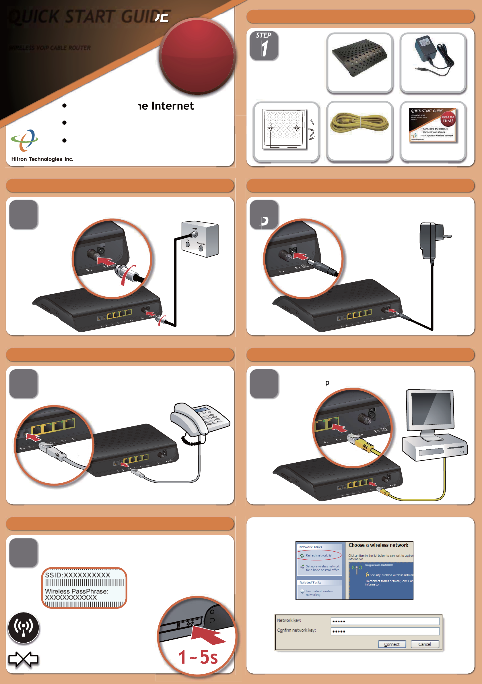
QUICK START GUIDE
HITRON
WIRELESS VOIP CABLE ROUTER
Connect to the Internet
Connect your phones
Set up your wireless network
Read me
first!
1
STEP
Check the package contents
1 Router
1 ETHERNET CABLE QUICK START GUIDE
1 POWER ADAPTOR
2
STEP
Connect the cable port
Connect your cable outlet to the device’s CABLE connector.
3
STEP
Connect the power
Connect the power adaptor to the POWER port.
4
STEP
Connect your phones/fax machines (CVE Series only)
Use the cables to connect your phones and fax machines to the
LINE ports.
Do this only if you ordered phone/fax service.
5
STEP
Connect wired computers (optional)
You can use the included Ethernet cable to connect a computer to
one of the LAN orts.
6
STEP
Connect wireless computers (optional)
You can connect devices to the wireless network. Look at the
sticker on the bottom of the device, and make a note of the SSID
and Wireless PassPhrase.
Next, look at the LEDs (lights) on the
front of the device. Is the Wireless
LED on, or blinking?
If so, the wireless network is on.
If not, turn the wireless network on by
pressing the WIFI button on the side
of the device for at least 3 seconds.
1~5s
On your computer, open your wireless network utility (this example uses
Windows XP). Refresh the network list and locate your device’s SSID.
Click Connect. The next screen shows that you are securely connected.
Select the network. In the next screen, enter the Wireless PassPhrase.
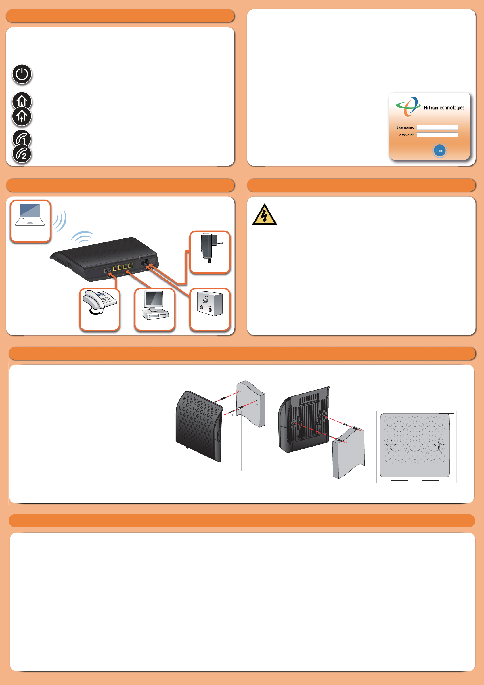
157mm (6.18inch)
103 mm (4inch)
Mounting Kits
Setup Complete
LED Display
Congratulations! You have successfully set up your router. If you have
any problems, see the sections below for help identifying the problem.
* Up to ten minutes on first connection, two minutes thereafter.
POWER: this LED turns on when power is connected and the
router is turned on. If it does not, your router is not receiving
power.
UPSTREAM/DOWNSTREAM: these LEDs blink while the router is
searching for a connection over the Internet, and shine steadily once
a connection is established. If they continue to blink for longer than
expected*, the router cannot make a connection.
LINE 1/LINE 2: (CVE Series only) these LEDs turn on if you have phone/
fax services.If you ordered one phone line LINE 1 turns on, and if you
ordered two lines, both LEDs turn on.
IP addresses
If your router is successfully connected to the network (see LED display)
but you cannot access the Internet from a connected computer, your
computer’s IP Address may be set up wrongly. In your computer’s control
panel either ensure that the computer is configured to receive an IP address
automatically (recommended) or ensure that it has a static IP address in the
range 192.168.0.2~192.168.0.254. For more information, consult your
Operating System’s document.
Configration interface
Your router has a configuration interface
allowing complete control over the
device’s behavior. In a Web browser, enter
192.168.0.1 in the address bar. In the screen
that displays, enter admin as the username
and password as the password.
Connection options
POWER
CABLECOMPUTERS
PHONES/
FAXES
WIRELESS
DEVICES
STEP
Safety Warnings
WARNING
DISCLAIMER
COPYRIGHT © 2011 HITRON TECHNOLOGIES, INC.
Notes
Wall-mounting lnstallation
The mounting holes seperated by 157mm/ 6.18inch on the
bottom of device. You may drive two nails or screws with the
head size in a diameter of 7.00mm/ 0.28inch and a thickness
of 2.7mm/ 0.11inch into the wall to make sure of the nails or
screws are capable of withstanding 2.5k load.You also can
use the little pack with tapping screws and plastic anchors in
box to mount this device on the wall. The steps of wall-mounted
installation are
(1) Drill two holes with diameters of 6.5mm/ 0.25inch, in distance
of 157mm/ 6.18inch on the wall.
(2) Nail the plastic anchors into the holes and make sure the
whole anchors were inserted in the wall.
(3) Screw the tapping screws in the anchors and expose the
appropriate length at the screw head to hang the device.
There are limitations if plastic anchors are used. The wall
surface must be:
1. Fir and pine with a thickness of over 32mm/ 1.25inch;timber
or plywood that is capable of withstanding 2.5k load.
2. Brick wall with a thickness of over 32mm/ 1.25inch.
3. Concrete wall with a thickness of over 32mm/ 1.25inch
4. Metal wall with a thickness of over 15mm/ 0.6inch
157mm (6.18inch)
103 mm (4inch)
Wall
Hole Drilling
Diameter 6.50mm/ 0.25inch
Tapping screw
Plasticanchor
Wall
The drilling orientation of the actual size is
included in the box.Before drilling holes
on the wall, you can place this orientation
diagram on the wall first and drill holes
P/N:0440010108N0(2A)
NCC Warning Statement
Article 12
Without permission, any company, firm or user shall not alter the frequency, increase the
power, or change the characteristics and functions of the original design of the certified
lower power frequency electric machinery.
Article 14
The application of low power frequency electric machineries shall not affect the naviga-
tion safety nor interfere a legal communication, if an interference is found, the service
will be suspended until improvement is made and the interference no longer exists.
The manufacturer assumes no liabilities with respect to the contents of this document.
The manufacturer also reserves the right to revise this document or update the content
thereof without any obligation to notify any person of such revisions or amendments.
Specifications subject to change without notice.
Risk of electrical shock. Do not expose the device to water or moisture. The device is a
high-performance communications device designed for home and office environments.
Do not use the device outdoors. Keep the device in an environment between 0°C ~ 40°C
(32°F ~104°F). To avoid overheating, do NOT place any object on top of the device. Do
not restrict the flow of air around the cable modem. The manufacturer assumes no
liabilities for damage caused by any improper use of the device.
FCC statement in User’s Manual (for class B)
“Federal Communications Commission (FCC) Statement
This Equipment has been tested and found to comply with the limits for a class
B digital device, pursuant to Part 15 of the FCC rules. These limits are
designed to provide reasonable protection against harmful interference in a
residential installation. This equipment generates, uses and can radiate radio
frequency energy and, if not installed and used in accordance with the
instructions, may cause harmful interference to radio communications.
However, there is no guarantee that interference will not occur in a particular
installation. If this equipment does cause harmful interference to radio or
television reception, which can be determined by turning the equipment off and
on, the user is encouraged to try to correct the interference by one or more of
the following measures:
- Reorient or relocate the receiving antenna.
- Increase the separation between the equipment and receiver.
- Connect the equipment into an outlet on a circuit different from that to which
the receiver is connected.
- Consult the dealer or an experienced radio/TV technician for help.
FCC Caution:
1. This device complies with Part 15 of the FCC rules. Operation is subject to
the following two conditions:
(1) This device may not cause harmful interference, and
(2) This device must accept any interference received, including interference
that may cause undesired operation.
2. This device and its antenna(s) must not be co-located or operating in
conjunction with any other antenna or transmitter.
3. Changes or modifications to this unit not expressly approved by the party
responsible for compliance could void the user authority to operate the
equipment.