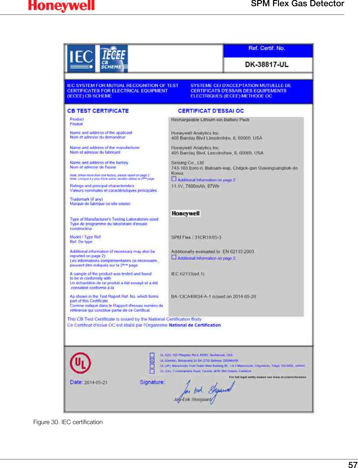
Honeywell Analytics SPMFLEX RFID Chemcassette Recognition User Manual Manual 2
Honeywell Analytics Inc RFID Chemcassette Recognition Manual 2
UserManual.wiki
>
Honeywell Analytics
>
SPMFLEX User Manual
>
Manual 2
Contents
1.
Manual 1
2.
Manual 2
Manual 2
Navigation menu
Upload a User Manual
Namespaces
Wiki Guide
HTML
PDF
Info
Views
User Manual
Discussion / Help
Navigation
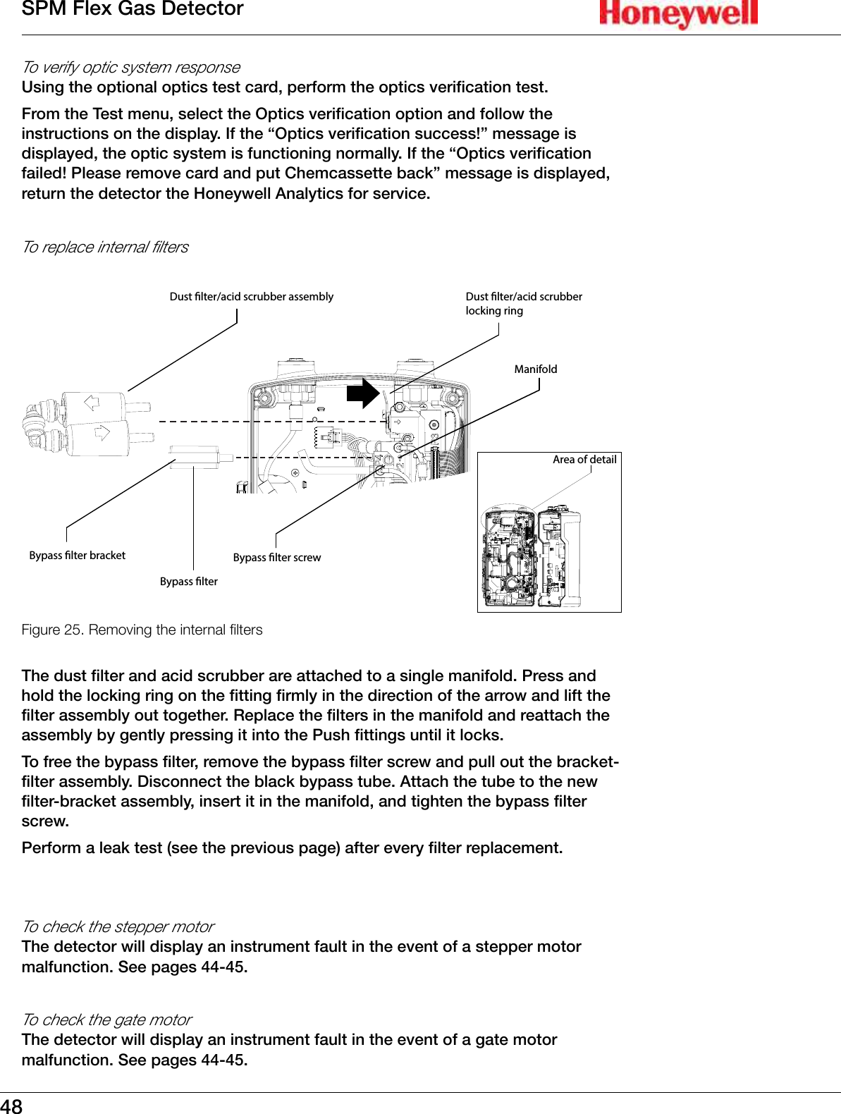
![34SPM Flex Gas DetectorThe display can be configured for different backlight and dimming options� By default the backlight will dim after a few minutes of no activity� The display can be configured to turn off the backlight entirely after a set period of time�InhibitWhen the detector is in inhibit mode, it will show a bell icon with a red slash through it� 1� Use the [Up] or [Down] buttons to select the “Inhibit” on the Maintenance menu�2� Press the [Accept] button�3� The Inhibit Type menu or the Time Out menu can then be selected� Possible inhibit types are none, alarms only, faults only, alarms and faults, and all, as shown in the following table)� The Time Out options (the time until the detector exits inhibit mode and returns to active monitoring) are from 1 to 60 minutes� 4� To take the unit out of inhibit, select “None” from the Inhibit Type menu and press the [Accept] button twice to return to the Maintenance menu� If the inhibit times out before the inhibit state is returned to “none,” maintenance fault code M17 will be displayed� NOTE](https://usermanual.wiki/Honeywell-Analytics/SPMFLEX.Manual-2/User-Guide-2373719-Page-6.png)