Honeywell orporated DR4220 Proximity Reader User Manual Frontmtr
Honeywell International Incorporated Proximity Reader Frontmtr
Contents
- 1. Manual
- 2. Users Manual
Manual

Models Supported:
DR4200K
DR4201
DR4203
DR4205 (K, E, GM)
DR4208S
DR4220
DigiReader
™
Series
P/N 6600025 Rev. D
PHONE (510) 360-7800
FAX (510) 360-7820
an ISO 9001 certified company
INSTALLATION
and
OPERATION
47102 Mission Falls Court
Fremont, CA 94539-7818

ii P/N 6600025, Rev. D
DigiReader Series
© Copyright 2000 WSE
All rights reserved. Printed in the United States of America.
NexSentry™, QuadraKey™, NexKey™, KeyMate™, 2Smart™, and DigiReader™ are trademarks of
WSE.
ProProx™, ISOProx™, DuoProx™, and Corporate 1000™ are trademarks of HID Corporation.
Teflon™ is a trademark of the DuPont Corporation.
Printed in the U. S. A.

P/N 6600025, Rev. D iii
DigiReader Series WSE
LIMITED WARRANTY
WSE warrants to the original user the equipment manufactured by WSE as described herein to be free
from defects in material and workmanship for a period of one year from the date of purchase by such user
or fifteen (15) months from the date of shipment from the factory, whichever is sooner (command key/
magnetic stripe card warranties differ, see below*), provided:
I WSE has been notified within such period by return of any alleged defective equipment, free and
clear of any liens and encumbrances to WSE or its authorized dealer at the address specified,
transportation prepaid;
II the equipment has not been abused, misused or improperly maintained and/or repaired during
such period;
III such defect has not been caused by ordinary wear and tear;
IV such defect is not a result of voltage surges/brownouts, lightning, water damage/flooding, fire,
explosion, earthquakes, tornadoes, acts of aggression/war, or similar phenomena;
V accessories used as integral to WSE systems have been approved by WSE (e.g., coaxial
cables, batteries, etc.);
VI the equipment has been installed, the installation supervised or installation tested by an
authorized WSE dealer.
WSE shall, at its option, either repair or replace, free of charge, the equipment found, upon WSE’s
inspection to be so defective, or if agreed upon, to refund the purchase price, less a reasonable allowance
for depreciation, in exchange for the equipment.
WSE MAKES NO OTHER WARRANTY, AND ALL IMPLIED WARRANTIES INCLUDING ANY WARRANTY
OF MERCHANTABILITY OR FITNESS FOR A PARTICULAR PURPOSE ARE LIMITED TO THE
DURATION OF THE EXPRESSED WARRANTY AS SET FORTH ABOVE.
WSE’S MAXIMUM LIABILITY HEREUNDER IS LIMITED TO THE PURCHASE PRICE OF THE EQUIPMENT.
IN NO EVENT SHALL WSE BE LIABLE FOR ANY CONSEQUENTIAL, INDIRECT, INCIDENTAL OR
SPECIAL DAMAGES OF ANY NATURE ARISING FROM THE SALE OR USE OF THE EQUIPMENT.
Some states do not allow limitations on incidental or consequential damages or on how long an implied
warranty lasts, so the above limitations may not apply. This warranty gives specific legal rights; however,
other rights which vary from state to state, may pertain.
Digital command key and magnetic stripe card warranties vary, according to the particular card used. See
the product literature.
The information in this manual is believed to be accurate and reliable. However, WSE assumes no
responsibility for any errors that may appear. Possession of this manual does not imply the granting of
licenses to make or sell equipment or software constructed according to descriptions provided.

iv P/N 6600025, Rev. D
DigiReader Series
FEDERAL COMMUNICATIONS COMMISSION RADIO
FREQUENCY INTERFERENCE STATEMENT
This device complies with part 15, sub-part C of the FCC Rules. Operation is subject to the following
two conditions:
1. This device may not cause harmful interference; and
2. This device must accept any interference received, including interference that may cause
undesired operation.
NOTE:
Regulatory labels are not attached at the factory. They are included in the ship-kit with
the PC-board and must be applied visibly to the enclosure (if purchased), or (if not)
to the back of the PC-board.

P/N 6600025, Rev. D v
DigiReader Series WSE
Table of Contents
COPYRIGHT AND TRADEMARK INFORMATION .............................................................................................. ii
LIMITED WARRANTY ........................................................................................................................... iii
FEDERAL COMMUNICATIONS COMMISSION RADIO FREQUENCY INTERFERENCE STATEMENT ................................. iv
INTRODUCTION ....................................................................................................................................1
GENERAL SPECIFICATIONS ....................................................................................................................2
DR 4205 SERIES SPECIFICATIONS .........................................................................................................3
BASIC OPERATION ...............................................................................................................................4
LED (AND BEEPER) OPERATION ..................................................................................................4
LED (AND BEEPER) (S-NET OPERATION) ...........................................................................................4
LED (WIEGAND OPERATION) ...........................................................................................................6
120-OHM TERMINATION JUMPER (INTERNAL/EXTERNAL) ..............................................................................7
INTERNAL INTERFACE CABLE FOR DR4200K, DR4201, DR4203, DR4205 (ALL MODELS), DR4208S
AND DR4220 ...............................................................................................................................7
RECOMMENDED S-NET CABLE ...............................................................................................................8
DIGIREADER ADDRESS SWITCHES ..........................................................................................................8
ROTARY ADDRESS SWITCHES FOR DR4200K, DR4203, AND DR4205 (ALL MODELS) ..............................8
DIP ADDRESS SWITCH FOR DR4201, DR4208S, AND DR4220 ........................................................9
SPECIAL FEATURES OF THE DR4201 AND DR4208S DIGIREADERS ........................................................... 11
READER OPERATION (S-NET MODE) ................................................................................................ 11
READER OPERATION (26-BIT AND 34-BIT WIEGAND MODE) .................................................................12
DR4205K SPECIAL OPERATING FEATURE ..............................................................................................13
NORMAL MODE ...........................................................................................................................13
KP-CREDENTIAL MODE ................................................................................................................14
TAMPER SIGNAL (S-NET ONLY) ............................................................................................................15
S-NET CONNECTIONS ........................................................................................................................15
WIEGAND CONNECTIONS ....................................................................................................................16
MOUNTING LOCATION .........................................................................................................................17
SPECIAL MOUNTING LOCATION: DR4201 READER .............................................................................18
TESTING THE DIGIREADER LOCATION ....................................................................................................20
GENERAL INSTALLATION ......................................................................................................................21
CABLE PREPARATION ....................................................................................................................21
DR4200K, DR4203, DR4205 SERIES, DR4208S AND DR4220 INSTALLATION ..................................21
WALL MOUNTING WITH SCREWS .........................................................................................................23
DR4203, DR4205 SERIES, DR4208S, AND DR4220.....................................................................23
WINDOW MOUNTING THE GLASS-MOUNTED UNITS .................................................................................. 24
TROUBLESHOOTING ...........................................................................................................................26
TUNE COMMAND (FOR THE NEXSENTRY STAR AND 4100-SERIES CONTROLLERS) ...................................26
CONTACTING WSE TECHNICAL SERVICE ...............................................................................................27
POSTAGE-PAID CUSTOMER COMMENT .............................................................................................. 29, 30

vi P/N 6600025, Rev. D
DigiReader Series
Tables
1DIGITAL READER SPECIFICATIONS ..............................................................................................2
1A DR4205 SERIES SPECIFICATION ..............................................................................................3
2 DR4205K/DR4200K SYSTEM LED/BEEPER BEHAVIOR, (BOTH DIGITAL READER AND
KEYPAD CAPABILITY ENABLED) .............................................................................................5
2A DIGIREADER SYSTEM LED/BEEPER BEHAVIOR, (ONLY READER CAPABILITY ENABLED) .........................6
2B DR4205K/DR4200K DYSTEM LED/BEEPER BEHAVIOR, WITH ONLY DIGITAL KEYPAD
ENABLED ........................................................................................................................6
3TERMINATION JUMPERS ...........................................................................................................7
4INTERNAL INTERFACE CABLE FOR DR4200K, DR4201, DR4203, ALL MODELS OF DR4205,
DR4208S, AND DR4220 .................................................................................................7
5RECOMMENDED S-NET CABLE ..................................................................................................8
6VALID SWITCH SETTINGS FOR SWITCHES 1 AND 2.......................................................................9
7 DR4201, DR4208S, AND DR4220 ADDRESS DIP-SWITCH SELECTIONS ....................................10
8 DR4205K NORMAL MODE SWITCH SETTINGS, SWITCHES SW1 AND SW2 ..................................13
9 DR4205K KP-CREDENTIAL MODE SWITCH SETTINGS, SWITCHES SW1 AND SW2 .......................14
10 TAMPER SWITCH(ES) ............................................................................................................15
11 RECOMMENDED WIEGAND CABLE GAUGE .................................................................................16
Figures
1THE DIFFERENT DIGIREADER MODELS (NOT TO SCALE) ...............................................................1
2 LED LOCATIONS FOR THE DIFFERENT DIGIREADER MODELS .........................................................5
3ADDRESS SWITCHES FOR DR4200K, DR4203, AND DR4205 (ALL MODELS) .................................8
4ADDRESS (DIP) SWITCH FOR DR4201/4208S/4220 SHOWING READER ADDRESS 1 SELECTED .......9
5 S-NET WIRING ...................................................................................................................15
6TYPICAL WIEGAND CONNECTION .............................................................................................17
7MOUNTING (DR4205 AND DR4208S) FOR OPTIMUM READ RANGE WITH METAL IN THE VICINITY ....18
8EUROPEAN AND US GANG BOX MOUNTING HOLES INDICATED ......................................................18
9 DR4201 MOUNTING HOLES INDICATED ...................................................................................19
10 DR4201 MOUNTING TEMPLATE (TO SCALE .PDF FILE ONLY)........................................................19
11 CABLE ROUTING CONFIGURATIONS ..........................................................................................22
12 SECURING THE DR4203, DR4205 SERIES, DR4208S AND DR4220 COVERS ............................23
13 DR4205GM: PLACEMENT OF DECAL AND READER ONTO GLASS ..................................................24
14 DR4205GM: ROUTING THE CABLE AND ATTACHING THE FACIA ....................................................25
DigiReader Series
P/N 6600025, REV. D 1
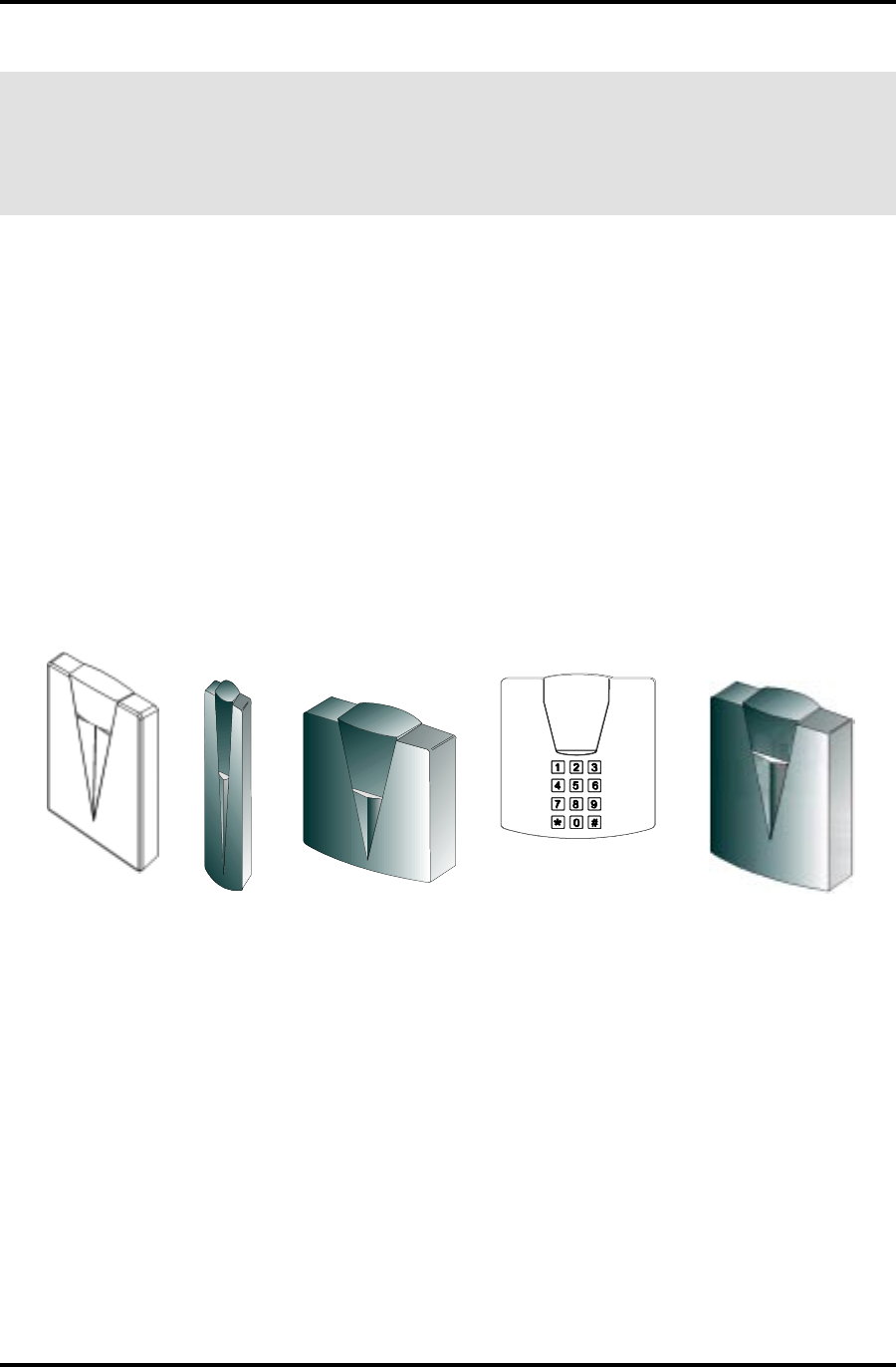
INTRODUCTION
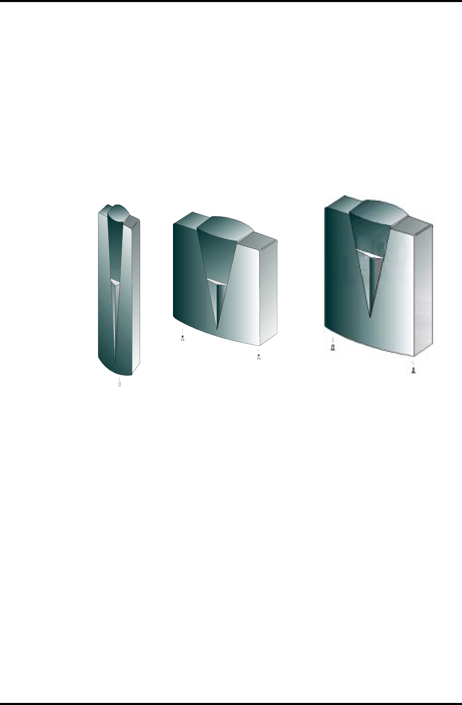
The DigiReader Series is a family of Digital Proximity Readers (DigiReaders). (Graphic represen-
tations of the DigiReader Series —not to scale— are shown in figure 1, below, and figure 2, on page
5.) DigiReaders are bi-directional security devices that read digital credentials, (from either side of
the sensor), at ranges from 1 to 20 inches (2½ to 51 cm), depending upon the model and the
environmental conditions. DigiReaders are used with the NexSentry 4100, 4102, 4104, Star I and
Star II (4100 Series), SE818SC and SE422 Access Control Units (ACUs), with the ACUs either
operating as stand-alone devices or operating in conjunction with a StarGaze, a NexSentry Manager
(NSM), a NexSentry Command Center (NSCC), (an SE6000), or an SE5850, WSE Access Control
Host System. Connection between a DigiReader and an ACU is over the WSE proprietary S-Net
interface or over a Wiegand interface to a Wiegand ACU. (The Wiegand data can be either 26- or
34-bit Wiegand standard.) (Also included in the DigiReader Series is a keypad-only reader, the
DR4200K, which is the only family member available with the analog 818SX ACU.)
CAUTION 1. Read this manual carefully before attempting to wire in place a DigiReader.
The warranty is void if damage occurs to the unit as a result of incorrect
wiring.
CAUTION 2. The information in this manual is not intended to conflict with the building codes,
electrical codes, fire codes, or safety codes required for any given installation.
In all cases, the prevailing building codes must take precedence.
DR4201 DR4203 DR4205/DR4208S
DR4205K/DR4200K
DR4220
Figure 1: The Different DigiReader Models (Not to Scale)
DigiReader Series
2 P/N 6600025, REV. D
GENERAL SPECIFICATIONS
Table 1: Digital Reader Specifications
*See Table 1A for details on DR4205 Readers
K0024RD 1024RD 3024RD 5024RD *seireS S8024RD 0224RD
noitpircseD K5024RD ,ekilA-kooL ylnOdraobyeK
/tsoctsewoL redaertsellams 'hctiwsthgil'rof sgnitnuomepyt
latigiD ytimixorp roodrofredaer snoillum
tnereffiD dnasngised sgnitnuom seiresnihtiw *
ytimixorplatigiD htiwredaer daerdesaercni egnar
ytimixorplatigiD htiwredaer daermumixam egnar
).hcnI(snoisnemiD3.1x0.5x0.57.0x8.4x3.32.1x5.7x8.1* 72.1x47.5x3.50.1x4.21x3.41
).mC(snoisnemiD2.3x7.21x7.218.1x2.21x4.80.3x0.91x5.4* 2.3x6.41x5.315.2x5.13x3.63
ycneuqerFtimsnarTANnoitarepoxelpudlluf,zHk231
ycneuqerFrevieceRANzHk66
revieceR noitaludomeD ANlangis)KSP(yeKtfihS-esahP
elcyCdaeRdraCANcesm001
:ecruoSrewoP teN-S Am08nahtssel,CDV82+ot61+ 82+ot21+ Am051<,CDV ,CDV82+ot31+ lanimonpmA6.0
:ecruoSrewoP dnageiW Am08nahtssel,CDV82+ot61+ 82+ot21+ Am051<,CDV
liatgiPdnageiW rotcennoC seY*
seY-S8024RD )oN-8024RD( seY-0224RD
UCAotecafretnI )ytilibapaceriw9( ,RO,dnageiWeriw-5tib-43/62+)mmocteN-S,584-SRrofdleihs+GWA22(riapdetsiwtlaud=liatgiperiw-9 tinUF/IdnageiWSNhtiw,seireS0014SNrof-dnageiWeriw-5etarapes+584-SReriw-4,)noitangisedW(
UCAotecafretnI )ytilibapaceriw4( /CS818/XX14( )sUCA224/XS818 -S,584-SRrofdedleihs,GWA22(riapdetsiwtlauD 224ESroCS818otlAroXX14SNrof-)mmocteN
noitapissiDrewoPsttaw2nahtsseL w71nahtsseL
srellortnoC .XS818-ylnoK0024RD:ETON.224ES,CS818otlA,seireS0014dnaIratSyrtneSxeN
srotacidnIelbammargorp,)der-wolley-neerg(roloc-irtelgniS
noitcetorPrepmaTseY
ytidimuH %09ot%01 gnisnednoc-non %09ot%01 gnisnednoc-non %09ot%01 gnisnednoc-non *%09ot%5 gnisnednoc-non %09ot%01 gnisnednoc-non
(erutarepmeT)F°051ot13-*051ot13-
(erutarepmeT)C°66ot53-*66ot53-
tnemnorivnEroodtuO/roodnIroodtuO/roodnIroodtuO/roodnI* esuroodtuOdnaroodnI
).sbL(thgieW57.03.01<* 57.3<
)smargK(thgieW43.211.054.0<*86.3.2<
tnailpmocADA :edulcnisseccadelbasidgnisaerofserutaeflaicepS;seY sutatssseccaetacidniotsrotacidnilausivdnaelbidua,sseccaeerf-sdnah
egnaRdaeR.xaM K0024RD 1024RD 3024RD 5024RD S8024RD 0224RD
)stinU(-).nI().mC().nI().mC().nI().mC().nI().mC().nI().mC(
yeKardauQAN5.1ot8.3ot3ot6.7ot4ot01ot6ot51ot61ot04ot
tramS2AN5.1ot8.3ot3ot6.7ot4ot01ot6ot51ot61ot04ot
yeKxeNAN5.1ot8.3ot3ot6.7ot4ot01ot6ot51ot61ot04ot
etaMyeKAN1ot5.2ot1ot5.2ot2ot5ot3ot8ot41ot53ot
.noitallatsnifotnemnorivnelacisyhpnognidnepedyravyamegnardaermumixaM

DigiReader Series
P/N 6600025, REV. D 3
DR 4205 SERIES SPECIFICATIONS
Table 1A: DR4205 Series Specifications
5024RD E5024RD MG5024RD K5024RD
noitpircseDredaerytimixorplatigiD redaerytimixorplatigiD rofdetaocyllamrofnoc esulanretxe
redaerytimixorplatigiD gniebfoytilibapachtiw detnuomssalg
redaerytimixorplatigiD detargetnihtiw rofdapyekfoorpretaw esuroodtuodnaroodni
ytilibapaCdnageiW :Wahtiwdetangisedsiroliatgiperiw-9sahledomfI MGW5024RDEW5024RDW5024RD
rellortnocotecafretnI )ytilibapaceriw9(
dna)noitacinummocteN-S,584-SRrofdedleihs,GWA22(riapdetsiwtlaudgniniatnocliatgiperiw-9 dnageiWeriw-5etarapes+584-SReriw-4,)noitangisedW(,RO,dnageiWeriw-5tib-43ro-62 tinUecafretnIdnageiWyrtneSxeNhtiw,seireS0014yrtneSxeNrof-
rellortnocotecafretnI )ytilibapaceriw4( )noitacinummocteN-S,584-SRrofdedleihs,GWA22(riapdetsiwtlauD 224ESroCS818otlAro,seireS0014yrtneSxeNrof-
snoisnemiD )mc2.3x6.41x5.31("72.1x"47.5x"3.5
ycneuqerFtimsnarTnoitarepoxelpudlluf,zhK041
ycneuqerFrevieceRzHk07
noitaludomeDrevieceRlangis)KSP(yeKtfihS-esahP
elcyCdaeRdraCcesm001
teN-S:ecruoSrewoP Am08nahtssel,CDV82+ot61+
dnageiW:ecruoSrewoP
noitapissiDrewoPsttaw2nahtsseL
srotacidnIelbammargorp,roloc-irtelgniS
noitcetorPrepmaTseY
ytidimuH %09ot%01 gnisnednoc %001ot%5 gnisnednoc %09ot%01 gnisnednoc %001ot%5 gnisnednoc
(erutarepmeT)F°021ot23051ot13-021ot23051ot13-
erutarepmeT)C°(94ot066ot53-94ot066ot53-
tnemnorivnEylnoesuroodnI dnadezirehtaeW roffoorp-hsalps esuroodtuo ylnoesuroodnI dnadezirehtaeW roffoorp-hsalps esuroodtuo
)secnuO(thgieW51429151
)smarG(thgieW024276235024
tnailpmocADA :edulcnisseccadelbasidgnisaerofserutaeflaicepS;seY sutatssseccaetacidniotsrotacidnilausivdnaelbidua,sseccaeerf-sdnah
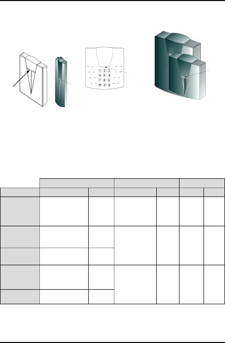
egnaRdaeRmumixaM sledoM5024RDllA
)stinU()sehcnI()sretemitneC(
yeKardauQ4otpu01otpu
tramS24otpu01otpu
yeKxeN4otpu01otpu
etaMyeK2otpu5otpu

DigiReader Series
4 P/N 6600025, REV. D
BASIC OPERATION
DigiReaders emit a low-level 140-kHz field. When a digital credential (card, KeyMate™, DuraTag™,
etc.) is placed in this field, a digital chip embedded in the credential uses the field’s energy for
activation. Once activated, the credential responds by broadcasting a 70-kHz signal, modulated
with a credential-specific code sequence, back to the reader. The reader receives this signal and
converts it to a digital code which is then sent to the ACU, (the Controller). The Controller identifies
the digital credential according to its code and makes either an access granted or an access denied
decision, based on credential information stored in the Controller's database or the host system's
database.
The DR4205K has a keypad on the face of the DigiReader. The keypad is used to enter the user’s
Personal Identification Number (PIN). The DR4205K keypad version can be configured for credential-
only use, or keypad-only use, or both, from the ACU DOOR Command. If the S-Net Reader Type
entry is set to DKR, the credential use will be activated for that door; set to NONE, the credential
use for that door will be de-activated; (– this is true for all DigiReaders except the DR4200K). For
the same door/reader combination, if the VIP Enable is set to Yes or No, the keypad portion will be
activated or de-activated, respectively.
The DR4200K is a keypad-only reader look-alike of the DR4205K, activated from the ACU DOOR
Command by setting VIP Enable (for that door) to Yes.
LED (AND BEEPER) OPERATION
LED (AND BEEPER) (S-NET OPERATION)
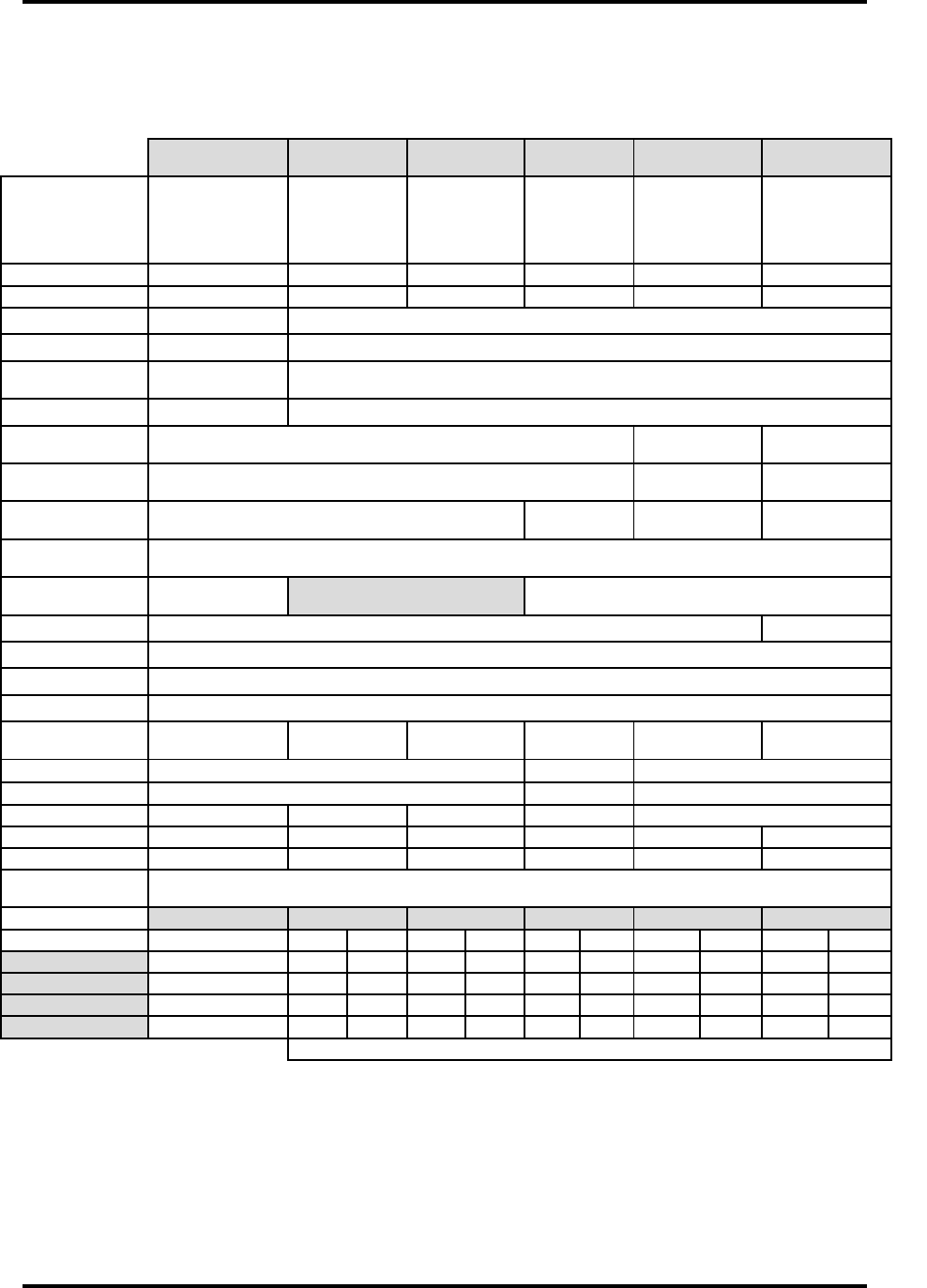
All DigiReaders have a single three-color (red-amber-green) LED controlled by the Access Control
Unit (ACU) to which the DigiReader is attached. Figure 2 shows the location of the LED on each
of the DigiReader models.
With the DigiReader on line to an ACU and with power applied, (the ready state), the DigiReader's
LED will be a constant red. When a DigiReader is configured to read digital credentials only (with
no keypad part of the DR4205K or VIP2 or DR4200K activated for the same door), a valid credential
will produce a momentary amber LED, followed by a green LED for the door unlock time or until the
door is closed following the credential-holder's access; (the LED will then return to the constant red).
With a keypad also activated, the amber LED will continue until either both the valid digital credential
and valid PIN, in either order, have been read/entered, producing the green unlock time LED, or until
the PIN grace period has been exceeded, producing the red LED. With only the keypad activated,
a valid PIN will produce the momentary amber, the unlock green and the return to the constant red.
DigiReader Series
P/N 6600025, REV. D 5
Figure 2: LED Locations for the Different DigiReader Models
NOTE: In each WSE security management system, the TUNE command (or its equivalent) is used
to specify LED and beeper behavior when a valid key is presented.
eniL-nO eniL-ffO omeD
sutatS DEL repeeB DEL repeeB DEL repeeB
laitnederCoN ottneSataD K0024oN,UCA yeKK5024ro desserP
derydaetSffO
derhsalF:elcyC ydaets,.ces4rof ,.ces4rofrebma .ces25rofffo
ffO ydaetS der ffO
laitnederCdilaV daeR
litnu,rebmaydaetS ecargroyrtneNIP dnedoirep
elgniS peeb rebmahsalF ylsuounitnoc sdnoces2.0~ dracelihw tneserp
peeB -nitnoc ylsuou ces8.0~ elihw drac tneserp
ydaetS &rebma 01~rof retfaces gnivomer drac
peeB yreve ces2~ elihw drac tneserp
dilavnI laitnederC rofffoydaetS emitelbasidredaer elgniS peeb
NIPdilaV deretnE
NIPlitnuderydaetS ydaets,deretne daerdraclitnurebma dnedoirepecargro
rofpeeB NIPhcae tigid deretne
derhsalF:elcyC ydaets,.ces4rof ,.ces4rofrebma .ces25rofffo morfdegnahcnu( rodesserpyekon )detneserpdrac
peeB rofecno yreve yek desserp
litnudeR syek6 ,desserp neht rofrebma 01~ sdnoces
peeB rofecno yreve yek desserp otpu( )6
NIPdilavnI litnurebmaydaetS dnedoirepecarg peeB tigidhcae
-yekdnaredaerlatigidhtob(,roivaheBrepeeB/DELmetsySK0024RD/K5024RD )roodemasnooslaredaeRigiDhtiw,K0024RDfi.....()delbaneytilibapacdap
)gnimmargorpUCAybdenimreted,lortnocUCArednuroivahebDEL(
Table 2:
The complete operational characteristics (LED and beeper behavior) for a DigiReader with or without
keypad, or with the keypad only used, are shown, (respectively), in Tables 2, 2A and 2B, below.
DR4201
LED
DR4203
LED
LED
DR4205K/DR4200K
DR4205/4208S/4220
LED

DigiReader Series
6 P/N 6600025, REV. D
eniL-nO eniL-ffO omeD
sutatS DEL repeeB DEL repeeB DEL repeeB
roK0024oN yeKK5024 desserP
derydaetSffO
derhsalF:elcyC ydaets,.ces4rof ,.ces4rofrebma .ces25rofffo
ffO ydaetS der ffO
NIPdilaV deretnE
NIPlitnuderydaetS yratnemom,deretne neergydaets,rebma /elbasidredaerrof emitneporood
rofpeeB NIPhcae tigid deretne
derhsalF:elcyC ydaets,.ces4rof ,.ces4rofrebma .ces25rofffo morfdegnahcnu( rodesserpyekon )detneserpdrac
peeB hcaerof tigidNIP deretne
litnudeR syek6 ,desserp neht rofrebma 01~ sdnoces
peeB rofecno yekyreve desserp )6otpu(
NIPdilavnI rebmaydaetS hcaepeeB tigid
delbanedapyeklatigidylnohtiw,roivaheBrepeeB/DELmetsySK0024RD/K5024RD
)gnimmargorpUCAybdenimreted,lortnocUCArednuroivahebDEL(
eniL-nO eniL-ffO omeD
sutatS DEL -peeB re DEL repeeB DEL repeeB
laitnederCoN ottneSataD UCA derydaetSffO
derhsalF:elcyC ydaets,.ces4rof ,.ces4rofrebma .ces25rofffo
ffO ydaetS der ffO
dilaV laitnederC daeR
neergydaetS skcolnuroodsa
peeB 5~ ces
rebmahsalF ylsuounitnoc sdnoces2.0~ dracelihw tneserp
peeB ylsuounitnoc ces8.0~ dracelihw tneserp
ydaetS &rebma 01~rof retfaces gnivomer drac
peeB yreve ces2~ elihw drac tneserp
dilavnI laitnederC rofffoydaetS emitelbasidredaer peeB ecno
)delbaneytilibapacredaerylno(,roivaheBrepeeB/DELmetsySredaeRigiD
)gnimmargorpUCAybdenimreted,lortnocUCArednuroivahebDEL(
Table 2A:
Table 2B:
LED (WIEGAND OPERATION)
The LED is controlled to be red or green by the level of the Wiegand LED control input. This is a
function of the particular Wiegand unit.
DigiReader Series
P/N 6600025, REV. D 7
120-OHM TERMINATION JUMPER (INTERNAL/EXTERNAL)
The jumper places 120 ohms of resistance between Data A and Data B for proper end-of-line
termination. Install the jumper only if the DR4200 Series DigiReader is the last device on the cable.
Table 3: Termination Jumpers
INTERNAL INTERFACE CABLE (FOR DR4200K, DR4201,
DR4203, DR4205--ALL MODELS, DR4208S * & DR4220)
An attached pigtail cable assembly provides the connection from the printed-circuit assembly and
keypad to the access control unit wiring on all of the following DigiReader models: DR4200K,
DR4201, DR4203, DR4205, DR4205E, GM, K and W, DR4208S ( - note the wider voltage range)
and DR4220. The cable is color coded as follows:
Table 4: Internal Interface Cable for DR4200K, DR4201, DR4203,
all models of DR4205, DR4208S, and DR4220
redaeR repmuJnoitanimreT redaeR repmuJnoitanimreT
*lanretnI noitacoL *lanretnI noitacoL
K0024RDseY1W**5024RDseY1W
1024RDseY1WS8024RDseY1W
3024RDseY3W0224RDseY1W
*sledom)TMS(ygolonhcettnuomecafrusnoelbaliavaylnorepmuJ W5024RDdnaK5024RD,MG5024RD,E5024RD,5024RD:sledomllA**
ROLOC NOITCNUF )esUteN-S( )esUdnageiW(
deR CDV82+ot61+ lanimoNteN-SlanimoNdnageiW
*CDV82+ot21+
neerGAteN-S ESWhtiwesuroF sseccateN-S slenaplortnoc AN
etihWBteN-S
kcalBnruteRCDnruteRCDteN-SnruteRCDdnageiW
dleihSdleihSlangiSdleihSteN-SnruteRCDdnageiWotdeiT:dleihSdnageiW
eulB)0tuO(0ataD
AN
slenaplortnocsseccadnageiWhtiwesuroF
egnarO)1tuO(1ataD
wolleY0DEL)deR( dellortnocUCAerasDELhtoB hgih/FFOrowol/NOeradna
nworB1DEL)neerG(
DigiReader Series
8 P/N 6600025, REV. D
RECOMMENDED S-NET CABLE
The type of cable used for the S-Net will depend on the total length and the number of devices
connected. Table 5 lists WSE-recommended cables:
Table 5: Recommended S-Net Cable
DIGIREADER ADDRESS SWITCHES
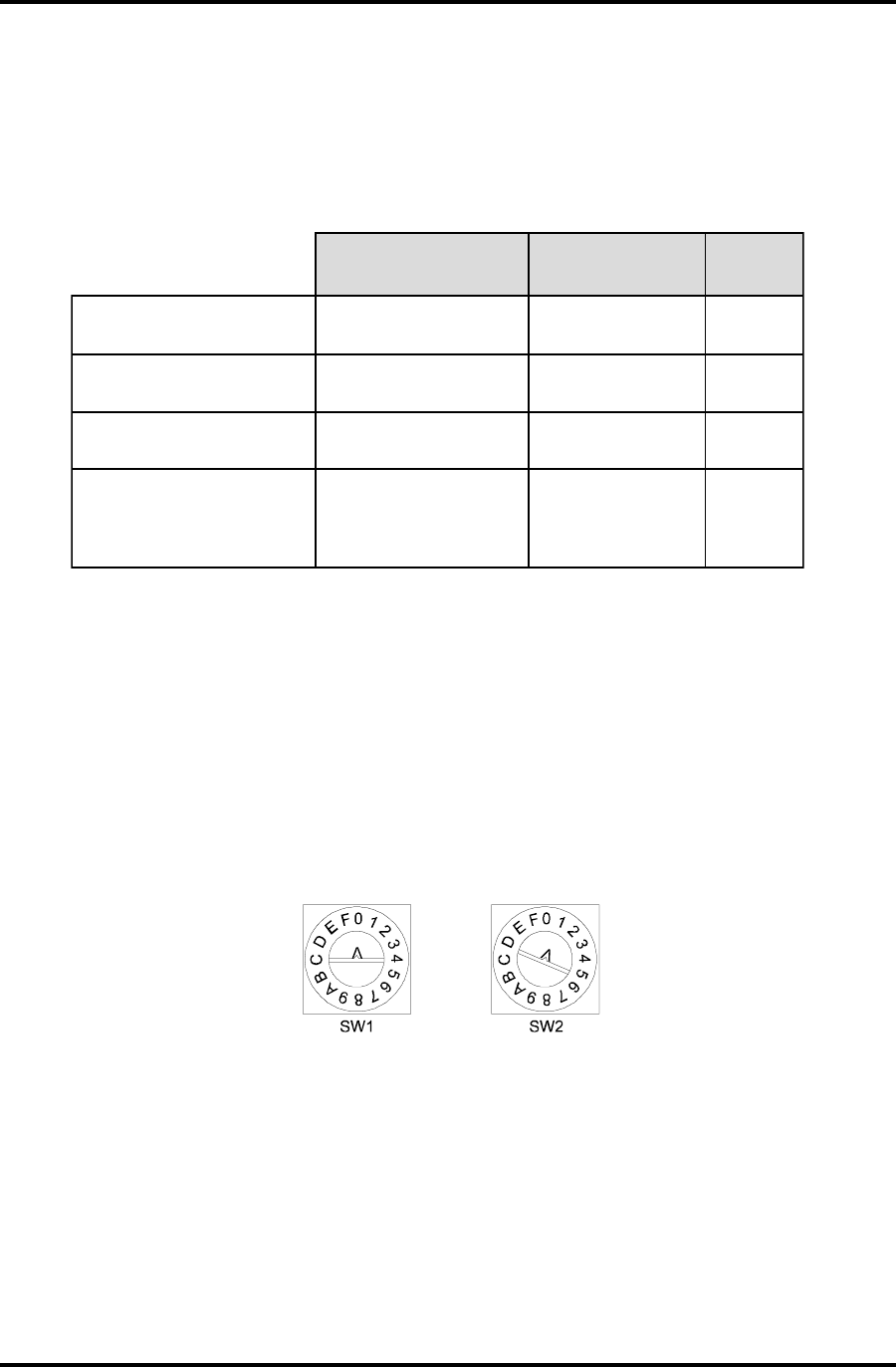
Rotary Address Switches for DR4200K, DR4203, and DR4205 (all models)
Each DigiReader must have a unique address. The DR4200K, DR4203, and DR4205 (all models)
DigiReaders use two address switches S1 and S2, (as shown in Figure 3):
Figure 3: Address Switches for DR4200K, DR4203, and DR4205 (all models)
• Switch SW1 is used to select the special reader modes of operation, (as shown in Table 6).
SW1 is set to 0 (factory default setting) for S-Net operation and F for Wiegand operation.
• Switch SW2 is used to set the Reader/Door address, and, with SW1 set to F, for additional
options, including (SW2 = A or B) the Wiegand number of bits. SW2 has a factory default
setting of 1, but it may be set to any address from 1 to F (15). A 16th DigiReader address is
provided by setting switch SW2 to 0 and switch SW1 to 8 (for Normal Mode), or C, D or E (for
DR4205K PIN/Credential Mode - see below).
ERUTCAFUNAM LACISYHP NOITPIRCSED EGUAG
.tF0004<rewoPdnaataD elbaC&eriWtsewhtuoS yarG/971WS ataD:rotcudnoC2 rewoP:rotcudnoC2 GWA22 GWA61
.tF005<rewoPdnaataD 2559nedleB 9601nedleB dedleihSriaP-2 GWA81 GWA61
.tF005>ylnOataD1489nedleBdedleihSriaP-1GWA42
.tF005>ylnOrewoP 1439nedleB 2431nedleB 3439nedleB rotcudnoC2 GWA81 GWA61 GWA41
DigiReader Series
P/N 6600025, REV. D 9
Valid addresses may be limited by the controller; (see the appropriate controller manual).
When used with an SE422, addresses 01 and 02 should be assigned to nodes 13 (VIP2/DR4200K)
and 15 (DKR), and 14 (VIP2/DR4200K) and 16 (DKR), respectively, see section 6 of the SE422
Installation Manual (p/n 66108328001), under Entry (Door) programming, questions 14 and 15.
Table 6: Valid Switch Settings for Switches 1 and 2
(* See DR4205K SPECIAL OPERATING FEATURE, page 11)
(** See NORMAL MODE, page 11 or PIN/CREDENTIAL MODE, page 12,
respectively, for S-Net address 16, Normal or PIN/Credential explanations)
(*** See TESTING THE DIGIREADER LOCATION, page 18)
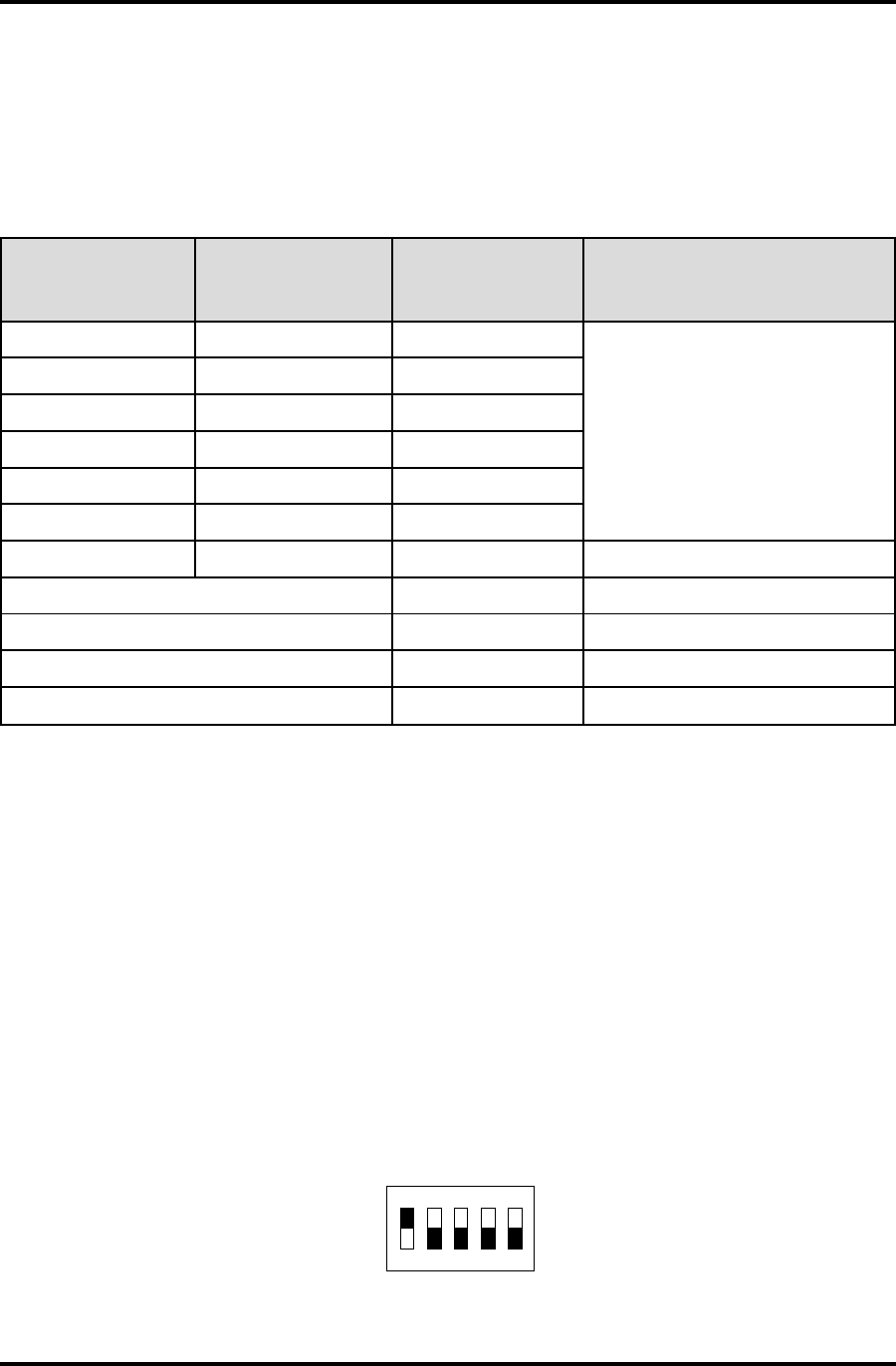
DIP Address Switch for DR4201, DR4208S, and DR4220
The DR4201, the DR4208S, and the DR4220 readers each have a 5-position DIP-switch S1, (as
shown in Figure 4, with S-Net address 1 selected), which combines the functions of the rotary
address switches S1 and S2 used by the other DR4200 Series DigiReaders.
Figure 4: Address (DIP) Switch for DR4201/4208S/4220 Showing Reader Address 1 Selected
*1WS )edoMlamroN(
*1WS
(NIP/ laitnederC edoM) 2WS NOITCNUF
06ro5,41
sesserddarooD/redaeR lamicedaxehF-1 )lamiced51-1(
06ro5,42
...
...
06ro5,4E
06ro5,4F
**8**EroD,C**0lamiced61sserddarooD/redaeR
FA tib-62dnageiW
FB tib-43dnageiW
FE edoMomeD
FF ***edoMtseTFR
NO
12345
FFO

DigiReader Series
10 P/N 6600025, REV. D
Table 7, below, shows the possible selections for S-Net address selection and Wiegand, DEMO mode
and TEST mode selections.
Table 7: DR4201, DR4208S, and DR4220 Address DIP-Switch Selections
)sgnitteS(1ShctiwS noitcnuF/sserddArooD/redaeR
1 2 3 4 5
ffOffOffOffOffO0enil-ffO
nO ffOffOffOffO1
ffO nO ffOffOffO2
nO nO ffOffOffO3
ffOffO nO ffOffO4
nO ffO nO ffOffO5
ffO nO nO ffOffO6
nO nO nO ffOffO7
ffOffOffO nO ffO8
nO ffOffO nO ffO9
ffO nO ffO nO ffO01
nO nO ffO nO ffO11
ffOffO nO nO ffO21
nO ffO nO nO ffO31
ffO nO nO nO ffO41
nO nO nO nO ffO51
ffOffOffOffO nO 61
ffO nO ffO nO nO )tib-62(ecafretnIdnageiW
nO nO ffO nO nO )tib-43(ecafretnIdnageiW
ffO nO nO nO nO edoMOMED
nO nO nO nO nO edoMTSET

DigiReader Series
P/N 6600025, REV. D 11
SPECIAL FEATURES OF THE DR4201 AND DR4208S
DIGIREADERS:
READER OPERATION (SNET MODE)
•The reader responds as both a DKR-type and an MSR-type device. The assigned address
message determines the reporting method for this reader.
•The RF field is powered at all times.
•The microcontroller uses a synchronous technique to sample the incoming data bits and shift
them into a 48-byte data buffer. The data collection and reporting techniques are key-type
dependent. The reader alternates between the two key types as follows:
•Key type 1 (WSE QuadraKey™, NexKey™, 2Smart™, and KeyMate™):
For 50 msec the key message data is serially shifted into a buffer while searching for an
88-bit PSK key message signal in WSE format. The received key data is validated if it
contains:
•the proper 8-bit preamble,
•a 32-bit reserved field,
•a 32-bit keycode field,
•a valid mode character,
•a valid parity character,
•a valid checksum byte, and
•the receive buffer contains two identical 88-bit key messages.
Reporting as an SNET DKR-type, only the key ID is reported to the ACU.
Reporting as an SNET MSR-type, the WSE key is reported to the ACU in an SNET MSR-
type log response with:
•key data in message characters 2-10,
•site code (always 9999) in message characters 11-14, and
•company code (always 9999) in message characters 19-22.

DigiReader Series
12 P/N 6600025, REV. D
•Key type 2 (HID ProxPro™, ISOProx™, DuoProx™, and Corporate 1000™):
For 120 msec the key message data is serially shifted into a buffer while searching for a
48-bit FSK-modulated Manchester-encoded signal. The received key data is valid if it
contains:
•a start character with 2 Manchester code violations,
•no other Manchester coding violations, and
•the receive buffer contains two identical 48-bit key messages.
Reporting as an SNET DKR-type, only the key ID is reported to the ACU.
Reporting as an SNET MSR-type, this key is reported to the ACU in an SNET MSR-type
log response. The MSR data sent depends on the key type recognized:
•26-bit key:
•key data in message characters 7-10,
•site code in message characters 11-14,
•company code (always 9999) in message characters 19-22.
•35-bit key:
•key data in message characters 6-10,
•site code in message characters 11-14,
•company code (always 9999) in message characters 19-22.
•37-bit key:
•key data in message characters 6-10,
•site code in message characters 11-14,
•company code (always 9999) in message characters 19-22.
•Only one keycode is received and reported at a time. A 1-second timer is started
when a key is read to prevent the same key from being repeated too quickly.
READER OPERATION (26-BIT AND 34-BIT WIEGAND MODE)
•The RF field is powered at all times.
•A digital key is received in the same fashion as for the SNET operation. (See above).
•If the key is in 88-bit WSE format, then either the 32-bit (or 26-bit) keycode is immediately
transmitted via the data 0 and data 1 lines, most-significant-bit first.
•If the key is a 48-bit type then the key content is checked to determine if 26-bit, 35-bit or
37-bit data is to be sent. If the content cannot be determined then no message is sent.
•Only one keycode is received and reported at a time. A 1-second timer is started when a
key is read to prevent the same key from being repeated too quickly.
DigiReader Series
P/N 6600025, REV. D 13
DR4205K SPECIAL OPERATING FEATURE
For the NexSentry 4100 Series ACUs, the DR4205K reader has two modes of operation, the Normal
Mode and the KeyPad-Credential (or KP-Credential Mode). Address switch SW1, ( the upper byte
of the address), determines mode selection. If SW1 is set to 0 or 8, the Normal Mode is selected.
If SW1 is set to 4, 5 or 6, (or C, D or E), the KP-Credential Mode is selected.
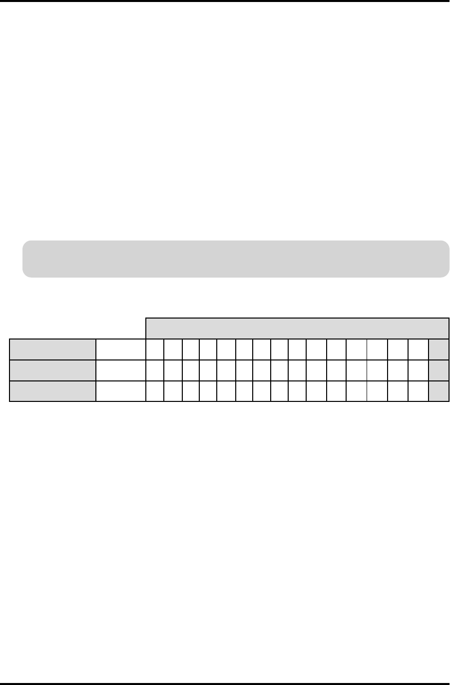
NORMAL MODE
With address switch SW1 set to 0, the DR4205K operates in its normal mode. Address switch SW2
is then set to the physical Reader/Door address of the DR4205K: 1 through 9 and A through F, (for
DigiReader addresses 1 through 15).
Since there are 16 possible reader addresses, a special provision is made to address the 16th
reader in the normal mode. For the 16th address, set switch SW1 to 8 and switch SW2 to 0.
(With both address switches SW1 and SW2 set to 0, a DigiReader is off-line.)
Table 8: DR4205K Normal Mode Switch Settings, Switches SW1 and SW2
Operation in Normal Mode:
DKR portion only enabled: the credential is sent as a credential, and no PIN is expected.
VIP portion only enabled: the PIN is sent as a PIN, with the number of PIN digits to be
entered set in the SYSTEM command. No credential is expected.
Both DKR and VIP portions enabled: the credential is sent as a credential, the PIN is
sent as a PIN. Both the credential and the PIN are expected (in either order). The number
of PIN digits to be entered is set in the PIN DIGITS entry of the SYSTEM command.
NOTE: Deselecting either the DKR or VIP portion requires powering off and on (or issuing
a RESET command in the terminal mode) to establish the deselected state.
edoMlamroN
sserddAredaeR )eniL-ffO( 123456789 01112131415161
1WS 0 0000000000000008
2WS 0 123456789A BC D E F 0
DigiReader Series
14 P/N 6600025, REV. D
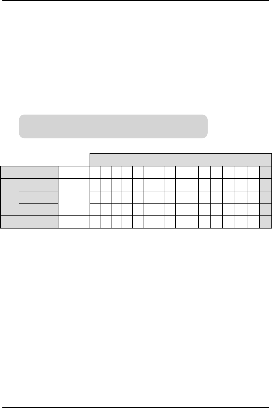
KP-CREDENTIAL MODE
With address switch SW1 set to 4, 5 or 6, the DR4205K operates in its 'KP-Credential' mode. In
the KP-Credential Mode the DigiReader operates in a special manner if only the DKR portion or the
VIP portion of the DigiReader is enabled: see Operation in KP-Credential Mode, below. The number
of digits in the KP-Credential is determined by the 4, 5 or 6 of address switch SW1. Address switch
SW2 determines the physical Reader/Door address of the DR4205K for nodes 1 to 15.
For the physical S-Net addresses 1 through 9, set switch SW1 to the S-Net values and switch SW2
to the number of KP-Credential digits, 4, 5 or 6. For Reader/Door addresses 10 through 15, set
switch SW1 to A through F and switch SW2 to the number of KP-Credential digits 4, 5 or 6.
For the 16th address, for a number of KP-Credential digits equal to 4, 5
or 6, set switch SW1 to C, D or E, respectively, and switch SW2 to 0.
(With both address switches SW1 and SW2 set to 0, a DigiReader is off-line.)
Table 9: DR4205K KP-Credential Mode Switch Settings, Switches SW1 and SW2
Operation in KP-Credential Mode:
NOTE: Enabling only either the DKR or VIP portion, as described below, i.e.deselecting
either the VIP or DKR portion, requires powering off and on (or issuing a RESET
command in the terminal mode) to establish the DKR-only or VIP-only state.
SW1 set to 4, 5, or 6 (or C, D or E): determines the number of KP-Credential digits, 4, 5
or 6, (which must match the number of digits set in the PIN DIGITS entry of the SYSTEM
command).
DKR portion only enabled: a credential presented (or a KP-Credential entered) is sent
as a credential.
VIP portion only enabled: a KP-Credential entered (or a credential presented) is sent as
a PIN.
Both DKR and VIP portions enabled: the operation is the same as for the normal mode.
edoMlaitnederC-PK
sserddAredaeR )eniL-ffO( 123456789 01112131415161
1WS
stigiDNIP4
0
444444444444444C
stigiDNIP5 555555555555555D
stigiDNIP6 666666666666666E
2WS 0 123456789A BC D E F 0
DigiReader Series
P/N 6600025, REV. D 15
TAMPER SIGNAL (S-NET ONLY)
DR4200 Series DigiReaders send a tamper signal to an S-Net-based Controller each time an
address switch (SW1 or SW2, described above) is changed. (The DR4201, DR4208S, and DR4220
have separate physical tamper switches.)
Table 10: Tamper Switch(es)
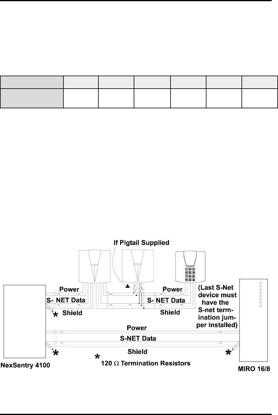
S-NET CONNECTIONS
The S-Net is an RS485 serial network for communication between the Controller and node devices.
Typically, the cable used is two twisted pairs with an overall shield; one pair is for data, the other
pair is for DC power. Terminate the last S-Net device with a 120-ohm, ¼ watt resistor or termination
jumper as shown in Figure 5. The maximum S-Net length is 4000 feet (1200 meters).
Figure 5: S-Net Wiring
:ledoMredaeRigiD K0024RD 1024RD 3024RD *5024RD S8024RD 0224RD
:)se(hctiwSrepmaT 1WSaiv 2WSro repmaTaiv 1WSro 1WSaiv 2WSro 1WSaiv 2WSro repmaTaiv hctiwS repmaTaiv hctiwS
MGW5024RDdnaMG5024RD,EW5024RD,W5024RD,K5024RD,5024RD:sledom5024lla*

DigiReader Series
16 P/N 6600025, REV. D
S-Net cable should only be installed in a daisy-chained fashion. WSE strongly recommends
replacing all crimp lug/soldered splices by daisy-chained connections in and out of each device.
(Note that up to two AD4305 NexStar RS485 Multiplexers may be used to simplify wiring and extend
a network.)
Where a pigtail cable is provided with the reader, a splice is required and the installer should, if
possible, keep the splice within 3 feet of the reader, to allow splice inspection at the reader location.
The type of cable used for the S-Net should be separate twisted-pair (data and power). See Table
5, above, for WSE recommended S-Net cables.
WIEGAND CONNECTIONS
Refer to Table 11 for the proper wire size for a particular cable length to use in a DigiReader Wiegand
application. Figure 6, below, illustrates a typical Wiegand connection.
Table 11: Recommended Wiegand Cable Gauge
DLEIHSHTIWELBACDNAGEIWROTCUDNOC-6
eziSeriWmuminiMhtgneLmumixaM
GWA22teeF002
GWA02teeF003
GWA81teeF005

DigiReader Series
P/N 6600025, REV. D 17
Figure 6: Typical Wiegand Connection
MOUNTING LOCATION
Use care when choosing the installation site. To avoid possible external sources of RF interference,
do not locate the unit near motors, pumps, generators, DC-AC converters, AC switching relays, light
dimmers, or any other devices that emit an electronic radar frequency. Do not locate the unit within
10 feet (3 m) of a computer terminal.
For the mounting of the DR4201 reader, see SPECIAL MOUNTING LOCATION: DR4201 READER,
on page 16.
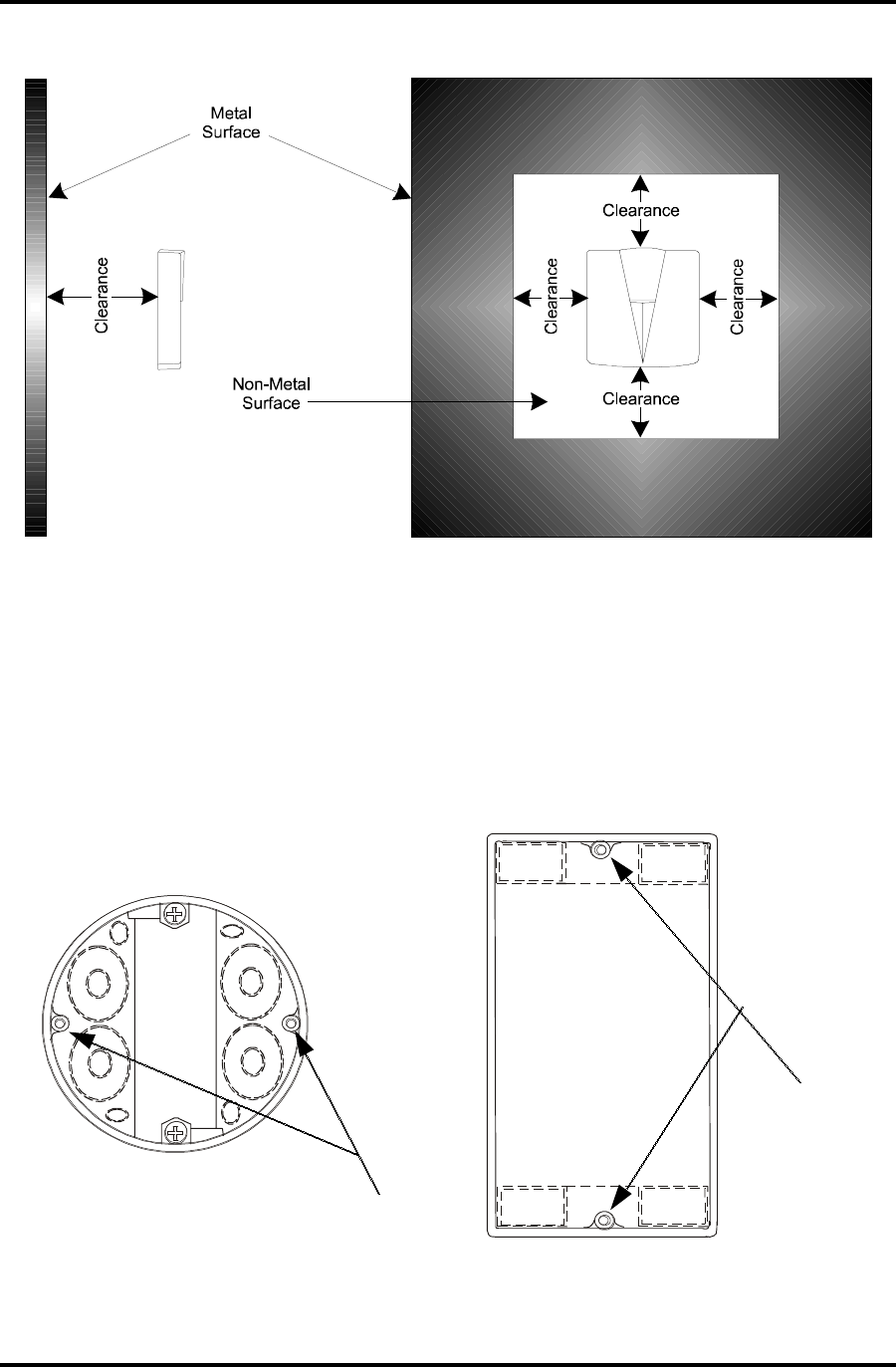
The DR4203, which is designed to be mounted on a metal door mullion, is the only reader that is
specifically designed to be mounted on metal. Metal in the vicinity of any of the other devices can
reduce the read range. In general, as the amount of metal in close proximity to the device increases,
the reliable maximum read range decreases. For optimum operation, ensure that a DigiReader has
a minimum of 6 inches (15 cm) clearance at the rear and surrounding sides, as shown in Figure
7. Never cover the front of the DigiReader with any type of metal.
Use the method appropriate to the mounting surface material; if required, use sealing compound to
maintain water-resistance.
+16 to +28 VDC
Common
Data A (+)
Data B (-)
Shield
NexSentry
Star I, Star II,
4100
Shield
+VDC
DC Return
Data 0
Data 1
LED 0
LED 1
Universal
Wiegand
Interface
Unit
(UWIU)
DR4205K
or
Third Party
Wiegand
Device
DC
Return
tied to ground
(Shield)
DigiReader Series
18 P/N 6600025, REV. D
Figure 7: Mounting (DR4205 and DR4208S) For Optimum Read Range With Metal In The Vicinity
SPECIAL MOUNTING LOCATION: DR4201 READER
The DR 4201 reader is designed to be mounted in a single-gang wiring box, (European or US), as
shown in figures 8 and 9, below, although it can be otherwise mounted. (Especially when mounted
outdoors, we recommend using a caulking compound around the edges of the unit after mounting.)
Figure 8: European and US Gang Box Mounting Holes Indicated
European
Mounting Holes
US Mounting
Holes
DigiReader Series
P/N 6600025, REV. D 19
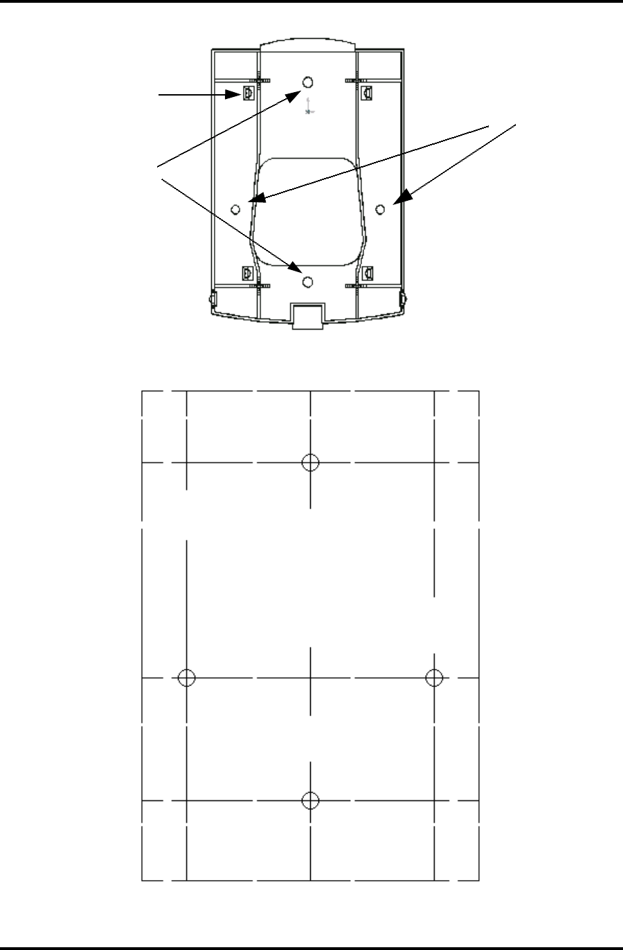
Figure 9: DR4201 Mounting Holes Indicated
Figure 10: DR4201 Mounting Template
(To Scale: .pdf file only)
Mounting Holes for
US Gang Boxes
Mounting Holes for
European Gang Boxes
Snap Fasteners x 4
CAUTIONARY NOTE:
Since the .pdf format slightly
shrinks all images, the original
.p65 image has been expanded so
that this .pdf image IS to scale.
(The distances between hole centers
are provided as an added safeguard.)
Hole A
Hole B
Hole C Hole D
A to B = 3.25 in. = 8.25 cm.
C to D = 2.36 in. = 6.00 cm.

DigiReader Series
20 P/N 6600025, REV. D
TESTING THE DIGIREADER LOCATION
If you suspect the presence of RF interference at a location where you plan to install a DigiReader,
you should check the site prior to mounting the DigiReader unit. The presence of RF interference
may affect a DigiReader in two different ways:
• If RF interference is present, the DigiReader unit may exhibit false reads (or 'ghost' reads),
i.e., the unit may beep and the LED illuminate, with no access credential present.
• Alternatively, with RF interference present, the DigiReader unit may read an access
credential inaccurately, slowly, or even may be prevented from reading the credential.
The following procedures will make it easier for you to identify a suitable location and to position the
DigiReader to minimize any RF interference:
1. The DigiReader models DR4200, DR4203, and DR4205 (all models) have two address switches,
SW1 and SW2. Set the switches on the DR4203 and DR4205 to FF for the test mode. The
DigiReader models DR4201, DR4208S, and DR4220 have a five-position dip-switch for the
address. Set all five dip-switch positions to ON for the test mode. Then perform the following
steps:
• Connect only the S-Net wires which provide power, (DC positive power and the DC return,
and the grounding shield), between the DigiReader and the controller.
• Hold the DigiReader against the installation surface.
• Verify that there are no cards or other credentials in the area capable of being detected
by the reader. (A credential in your pocket, or somewhere-else where it can be detected,
could be the source of any beeping, so you must be sure this is not the case.)
• If you are sure no credentials are present and the reader beeps, then there is RF
interference present, causing the beeping. (The number of beeps is an indication of the
degree of noisiness: more beeping indicates a more noisy environment than less beeping.)
• Keep testing locations until you find one where no false or 'ghost' reads occur.
2. With no false or 'ghost' reads occurring, and with the reader still in test mode, present a
credential to the reader . The reader should now beep, indicating that the card has been read.
(If the reader does not beep when the card is presented, there may be a source of RF present
blocking the reading of the card. In this case also, keep trying new locations,)
• With the credential reading correctly, verify the read time and the maximum read distance.
Using the charts on pages 2 and 3 (Tables 1 and 1A), you can determine the reader’s
capability with your chosen credential type(s). This same performance is what you would
expect once the system is completely installed.
3. When a suitably quiet location has been identified, (relatively free from RF noise), connect the
DATA A and DATA B wires between the DigiReader and the Access Control Unit.
• Set switches SW1 and SW2, for the DR4203 and DR4205 models (or, for the DR4201, the
DR4208S,or the DR4220, the 5-position dip-switch) to the correct address. With the

DigiReader Series
P/N 6600025, REV. D 21
GENERAL INSTALLATION
See the procedures for the reader model and installation type below for additional instructions.
CABLE PREPARATION:
1. Route the data and power cable to the DigiReader location and prepare the cable for attachment
to the DigiReader.
2. Remove two inches of the plastic jacket and the shielding foil from the cable.
3. Strip each wire back 1/4" for connecting to the DigiReader.
DR4200K, DR4203, DR4205 SERIES, DR4208S, AND DR4220 INSTALLATION:
1. The S-Net cable on the DigiReader may be routed from the back, bottom or the side of the
DigiReader. The reader is pre-configured for cable installation through the back mounting plate.
Note: S-Net cable is routed directly through the back on the DR4203, DR4208S, and DR4220,
and, from the back, on the side on the DR4205GM DigiReader only. (See Figures 11 and 16,
below), and on the back, through the gap made by removing the plastic notch on the DR4200K,
DR4205, DR4205E, and DR4205K DigiReaders.
2. For the DR4200K, DR4205, DR4205E, and DR4205K DigiReaders, remove the plastic notch
from the bottom of the cover. A rattail file may be used to enlarge the opening (Figure 11).
3. The DR4208S DigiReader cable is designed to be routed in two ways. The unit comes from
the factory with the cable, secured by a 'SW-NE' strap, routed through the hole in the middle
of the upper left quadrant (looking at the back of the unit). Alternately you can re-route the cable
through the bottom notch, (removed as in paragraph 2, above) by opening the case, carefully
removing the PCB (four screws), snipping the 'SW-NE' strap, securing the cable with a 'W-E'
strap, (via the holes provided for this purpose in the PCB), and re-assembling the unit.
controller now physically connected to the S-Net, and the address switch(es) set, set up
the controller to read credentials.
• Present a valid credential to the unit.
• Verify that the credential can be read from the expected distance.
4The read-range on the DigiReader should now be optimal, but,
• If trouble persists, verify the S-Net wiring and grounding, and / or
• Repeat steps 1, 2, 3, as necessary, to assure the best (most optimal) installed location.

DigiReader Series
22 P/N 6600025, REV. D
• Connect the DigiReader interface cable to the controller wiring run according to Table 4. If the
DigiReader is the last S-Net device on the S-Net cable run, install the termination jumper as
directed on page 7, 120 OHM TERMINATION JUMPER (INTERNAL/EXTERNAL), (Table 3).
• Set the address switch, as required.
and as an alternative for the DR4208S,
open the notch for routing the cable
through the bottom of the DigiReader
The DR4203
cable is routed
through the
back only
For the DR4200K
W-E
strap
Strapping holes
on DR4208S
SW-NE strap
and the DR4205 and
DR4220 DigiReaders,
Drill a 1/4" diameter
hole in the appropri-
ate side of the facia
for the DR4205GM
only (See Figure 15,
for the location)
Figure 11: Cable Routing Configurations
DigiReader Series
P/N 6600025, REV. D 23
DR4203
DR4205 Series and DR4208S
Figure 12: Securing The DR4203, DR4205 Series, DR4208S, and DR4220 Covers
WALL MOUNTING WITH SCREWS
DR4203, DR4205 SERIES, DR4208S, AND DR4220
• Mount the reader base to the wall. Use the WSE-supplied, 1 1/4" Flathead, #6-32 thread or
other means appropriate to the wall composition.
• Put the DigiReader cover in place and secure the cover with the supplied screw(s) from the
bottom.
DR4220
DigiReader Series
24 P/N 6600025, REV. D
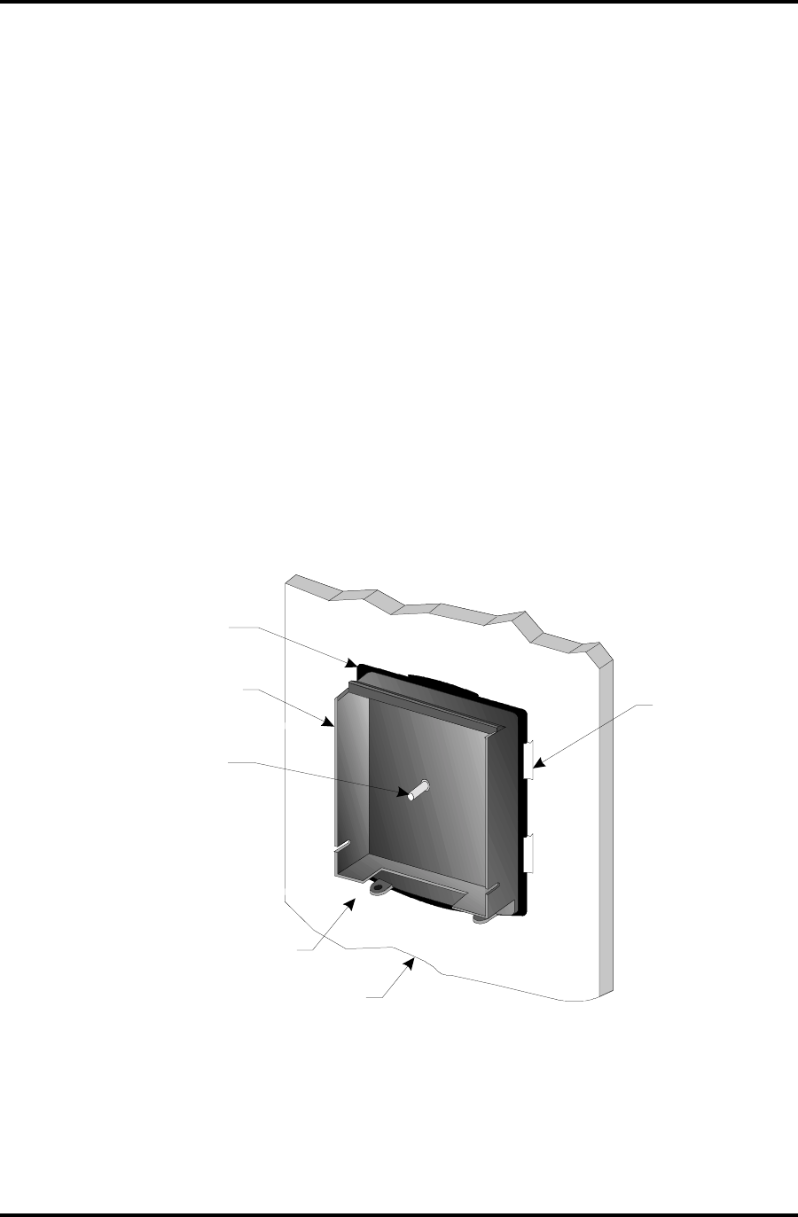
WINDOW MOUNTING THE GLASS-MOUNTED UNITS
This type of mounting is necessary for DR4205GM units.
1. Clean the window with glass cleaner or isopropyl alcohol and dry thoroughly.
2. Spray or wipe the window with slightly soapy water.
3. While the window is still wet, peel off the paper backing of the decal and press against the wet
section of the window and move around to release any air bubbles to assure maximum contact
with the window. Wipe dry any extra water coming out from the sides. See Figure 15.
4. Once the reader and decal are in place, it may be necessary to temporarily tape the reader to
the window while the adhesive sets. It should take approximately 10 minutes.
Figure 13: DR4205GM: Placement of Decal and Reader onto Glass
Decal (facing out)
Back Panel of DR4205GM
Reader
Light Pipe
(Aligns with the
LED in the Facia)
Wet Surface
Window Pane
Tape
Temporarily
DigiReader Series
P/N 6600025, REV. D 25
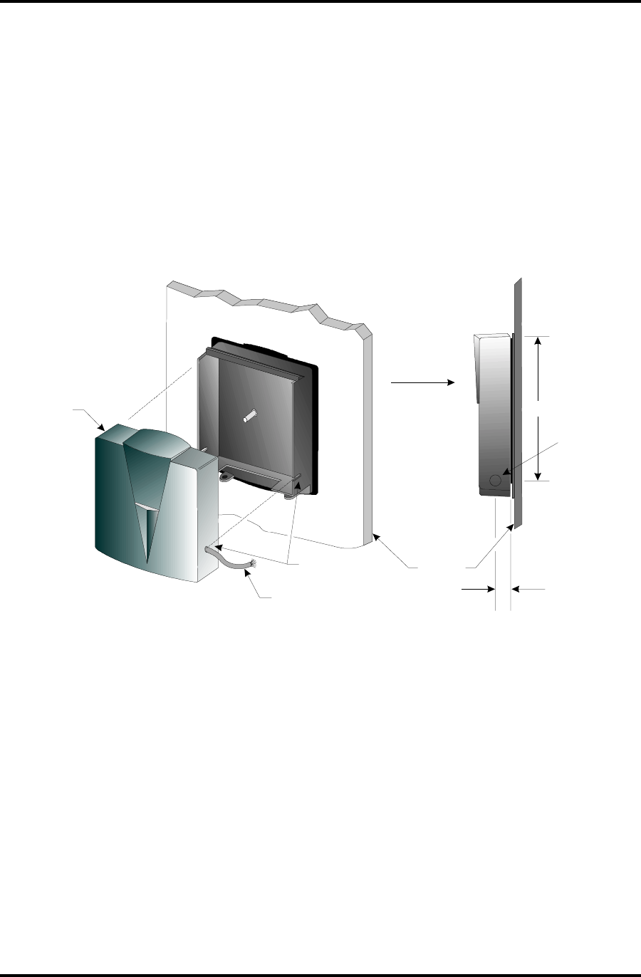
5. While the adhesive is setting, follow the general installation instructions on routing the cable
through the side channel and addressing the unit. After determining on which side the cable will
be routed through, drill a hole in that side of the front facia to match the pre-drilled slots in the
back panel of the reader.
Note: Reference page 20 for cabling instructions. Also see Figure 16 below.
6. Secure the cover as shown in Figure 13.
Figure 14: DR4205GM: Routing the Cable and Attaching the Facia
7. After the reader is securely set to the window, remove any masking tape used and clean the
window surrounding the reader.
DR4205GM
Reader Facia
S-Net Cable
Drill Hole to
Match Slot
Window
Pane
4.72" (12 cm.)
0.40" (1 cm.)
0.25" (0.63 cm.)
diameter

DigiReader Series
26 P/N 6600025, REV. D
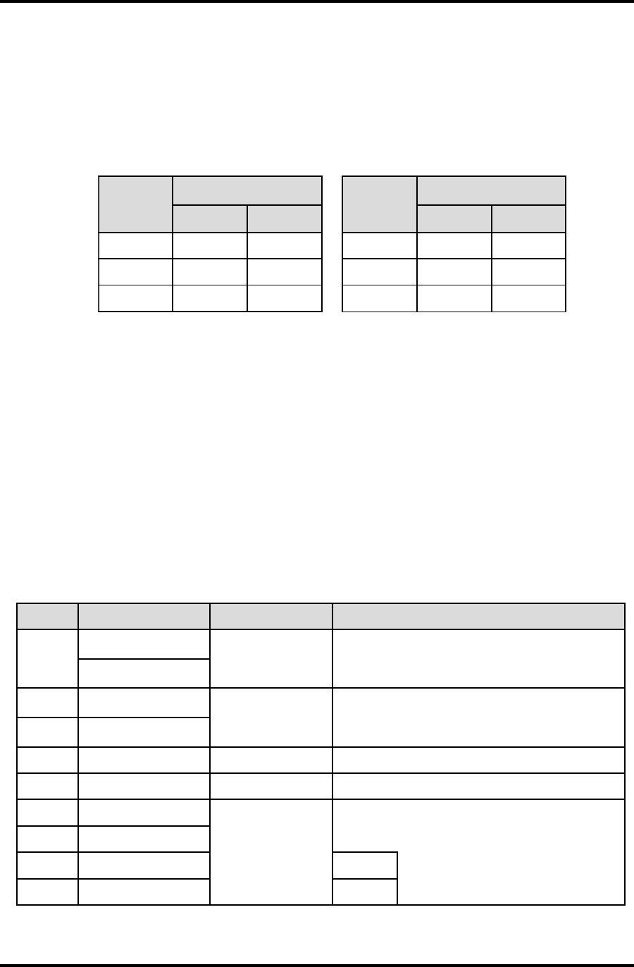
gnitoohselbuorT
noitacinummocdna,srorrenoitacinummoc,rewop:seirogetaceerhtotnillafsdohtemgnitoohselbuortdleiF snoitcadetseggussedivorpdnasnoitidnocesehtfosmotpmysnommoctsomehtstsilwolebelbatehT.seruliaf .melborpehtydemerdnayfitnediot
motpmySnoitcAgnitoohselbuorT
nitiltonDEL edomydaer rewopkcehC
ylppusrewopkcehC
rotcennocxineohPkcehC
sesufkcehC
sCIdetekcoskcehC
eruliaFmmoC
edomydaernitilDELkcehCevobaees,tonfI
teN-SkcehC snoitcennocelbackcehC
gnidnuorgylppusrewopkcehC
daeRoN daeRwolS egnaRdaeRtrohS )srorrEmmoC(
sMORPEkcehC
teN-SkcehC
noitanimrettcerrocyfireV
?ratSxeNdeen-htgnelkrowteN
sgnidnuorgnommocyfireV
snoitcennocdleihskcehC
*dnammocENUTmrofreP
)sdaertsohG(sdaer-siMT:evobanoitcesehteeS ESTING THE DIGIREADER LOCATION
:woleb,dnammocENUTfonoissucsideeS*
TUNE Command (for the NexSentry Star and 4100-Series controllers)
YOUR COMMAND? TUNE
DOOR (1-16) ? 1 (door with a DKR reader)
1. DIGITAL KEY READER RANGE (0-255): 253 ? (power control)
2. SEND TO ACU ONCE (Y/N): Y ? (no. of times the DKR sends key to ACU)
3. NUMBER OF VERIFICATION KEY READS (0-255): 0 ?(no, of retries, for high RF environment)
4. VERIFICATION TIME WINDOWS (0000-FFFF): 20 ? (hex 20 = decimal 32)
5. BEEPER BEHAVIOR WITH A VALID KEY
ON DURATION (0000-FFFF): A ? (hex A = decimal 10)
OFF DURATION (0000-FFFF): A ?
ON-OFF TOOTAL DURATION (0000-FFFF): 14 ? (hex 14 = decimal 20)
NOTE: DR4201, DR4208S, and DR4220 readers use only question 5, for the beeper.

DigiReader Series
P/N 6600025, REV. D 27
CONTACTING WSE TECHNICAL SERVICE
Telephone:
United States:
1-800-227-1667 (voice: toll free)
or
1-510-360-7996 (voice)
6:00am —to— 6:00pm
(Pacific Time Zone = GMT - 8 hours)
Monday through Friday
1-510-360-7823 (fax)
Europe (Germany):
+49 (0) 70 31 637 782 (voice)
8:30am —to— 12:00noon & 1:00pm —to— 4:15pm
(Central European Time Zone = GMT + 1 hour)
Monday through Friday
+49 (0) 70 31 637 769 (fax)
NOTE: The German telephone numbers should be used for
technical service for the whole of Europe.
The United States telephone numbers should be used for
technical service for the rest of the world.
E-mail:
wsehelp@wse.com
Web Site:
http://www.wse.com

DigiReader Series
28 P/N 6600025, REV. D
This Page Intentionally Left Blank

DigiReader Series
P/N 6600025, REV. D 29
Name of Manual: DigiReader Series: Installation and Operation Manual
Part Number: P/N 6600025 Revision: D
Organization: ________________________________________________________________
________________________________________________________________
Address: ________________________________________________________________
________________________________________________________________
________________________________________________________________
________________________________________________________________
OtherEquipment Ordered
With Your
DigiReader(s):
Evaluation of Manual:
POOR FAIR ADEQUATE GOOD EXCELLENT
Organization: 12345NA
Content: 12345NA
Style: 12345NA
Thoroughness: 12345NA
Clarity (Words): 12345NA
Clarity (Figures): 12345NA
Clarity (Tables): 12345NA
Were you able / was your integrator able to set
up your DigiReader(s) by using this manual? Y N NA
and/or Did you have to call Customer Service for help on one
or more issues? Y N NA
What additional aid(s) did you use to bring up your equipment?
________________________________________________________________
________________________________________________________________
Other Comments
(Positive): ________________________________________________________________
________________________________________________________________
________________________________________________________________
________________________________________________________________
Other Comments
(Negative): ________________________________________________________________
________________________________________________________________
________________________________________________________________
________________________________________________________________
Please tear off this sheet, fill it out, and return it within 3 months of system installation.

DigiReader Series
30 P/N 6600025, REV. D