Honeywell orporated DR4220 Proximity Reader User Manual 7600033D 4220 4 5 02
Honeywell International Incorporated Proximity Reader 7600033D 4220 4 5 02
Contents
- 1. Manual
- 2. Users Manual
Users Manual
August 2, 2006 Document 7600033
© 2006 Honeywell International. All rights reserved. Revision F
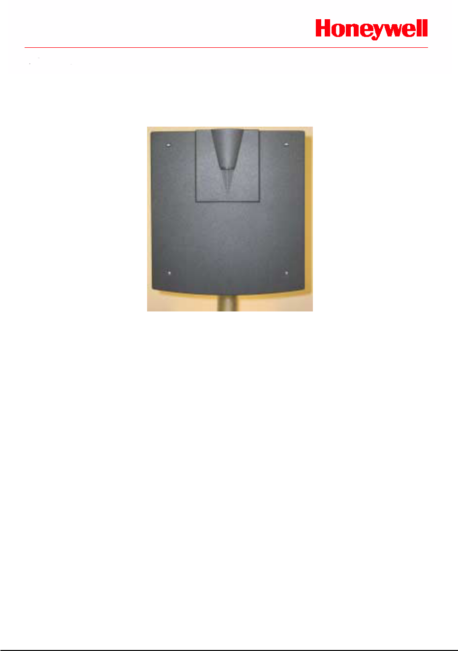
Installation Notes
DigiReader ® DR4220
IC: 573G-DR4220
FCC ID: C4PDR4220
(The term "IC:" before the radio certification number only signifies that Industry Canada technical specifications were met.)
Operation is subject to the following two conditions: (1) this device may not cause interference, and (2) this
device must accept any interference, including interference that may cause undesired operation of the device.
Changes or modifications not expressly approved by the party responsible for compliance could void the
user's authority to operate the equipment.
Note: This equipment has been tested and found to comply with the limits for a Class B digital device,
pursuant to part 15 of the FCC Rules. These limits are designed to provide reasonable protection against
harmful interference in a residential installation. This equipment generates, uses and can radiate radio
frequency energy and, if not installed and used in accordance with the instructions, may cause harmful
interference to radio communications. However, there is no guarantee that interference will not occur in a
particular installation.
If this equipment does cause harmful interference to radio or television reception, which can be determined
by turning the equipment off and on, the user is encouraged to try to correct the interference by one or more
of the following measures:
• Reorient or relocate the receiving antenna.
• Increase the separation between the equipment and receiver.
• Connect the equipment into an outlet on a circuit different from that to which the receiver is
connected.
• Consult the dealer or an experienced radio/TV technician for help.
DigiReader DR4220 Installation Notes
DIGIREADER DR4220 INSTALLATION NOTES
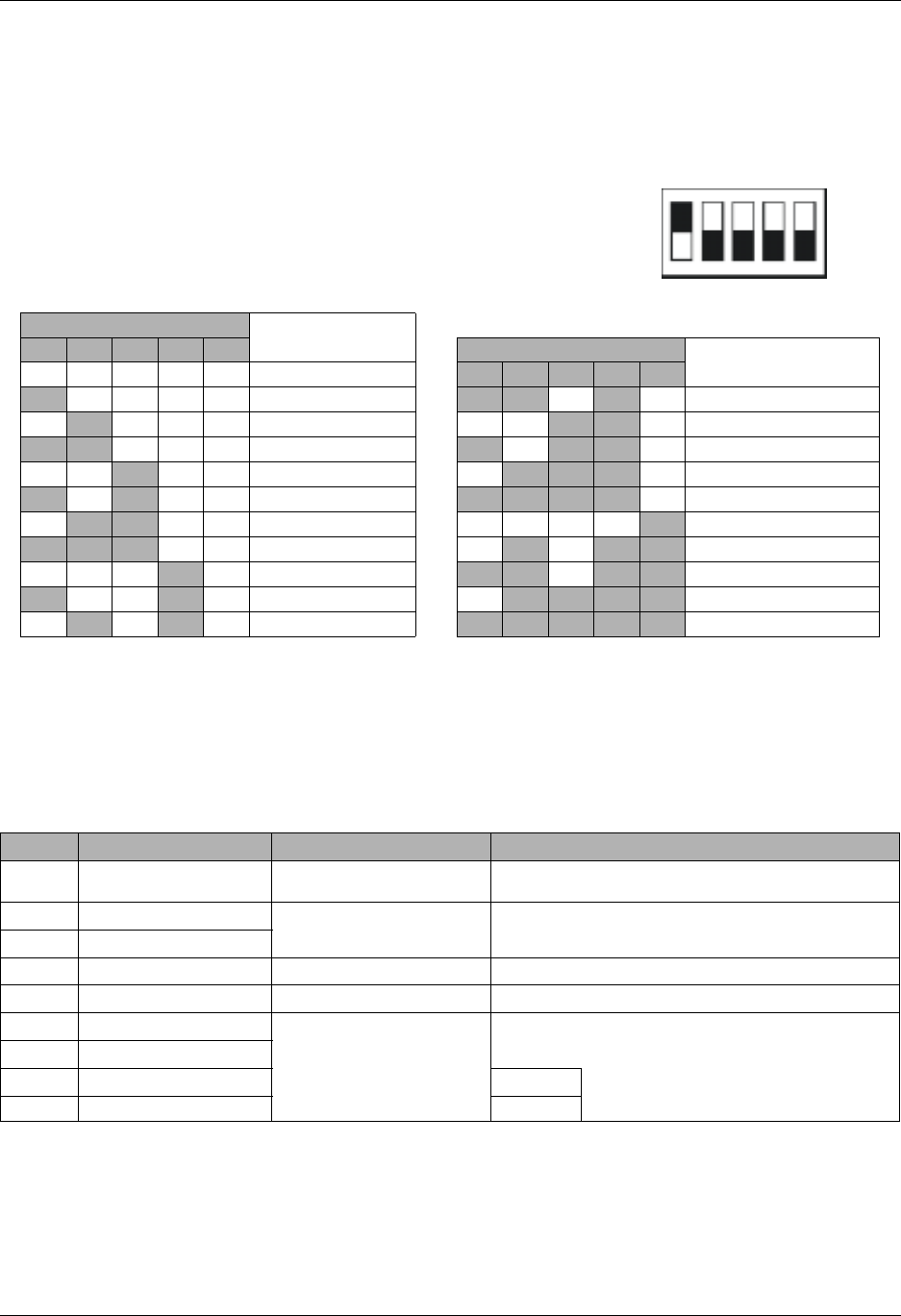
DIP ADDRESS SWITCH
TheDR4220readerhasa5-positionDIP-switchS1,(as
shown to the right, with S-NET address 1 selected).
INTERNAL INTERFACE CABLE
An attached pigtail cable assembly provides the connection from the printed circuit
assembly to the access control unit wiring on a DigiReader DR4220. The cable is color-
coded as follows:
TAMPER
The DR4220 sends a tamper signal to an S-NET-based ACU when a tamper occurs.
Switch S1 Settings S-NET Address
or Function
12345 Switch S1 Settings S-NET Address
or Function
Off Off Off Off Off Off-line 0 12345
On Off Off Off Off 1 On On Off On Off 11
Off On Off Off Off 2 Off Off On On Off 12
On On Off Off Off 3 On Off On On Off 13
Off Off On Off Off 4 Off On On On Off 14
On Off On Off Off 5 On On On On Off 15
Off On On Off Off 6 Off Off Off Off On 16
On On On Off Off 7 Off On Off On On Wiegand I/F (26-bit)
Off Off Off On Off 8 On On Off On On Wiegand I/F (34-bit)
On Off Off On Off 9 Off On On On On DEMO Mode
Off On Off On Off 10 On On On On On TEST Mode
COLOR FUNCTION (S-NET Use) (Wiegand Use)
Red +12.5 to +24VDC
(max. draw 500mA)
S-NET Nominal Wiegand Nominal
Green S-NET A For use with NexWatch
access control panels NA
White S-NET B
Black GND S-NET DC Return Wiegand DC Return
Shield Earth S-NET Shield Wiegand Shield: Tied to Wiegand DC Return
Blue Data 0 (Out 0)
NA
For use with Wiegand
access control panels
Orange Data 1 (Out 1)
Yellow LED 0 (Green) Both LEDs are ACU-controlled
and are ON/low or OFF/high
Brown LED 1 (Red)
12 34 5
ON
OFF
P/N 7-600033 Rev. F1 ©Honeywell International. All Rights Reserved.
DigiReader DR4220 Installation Notes
MOUNTING INSTRUCTIONS:
Carefully choose the installation site to avoid possible external sources of RF interfer-
ence. Interference may cause reduced performance, so DO NOT locate the unit near
motors, pumps, generators, DC-AC converters, AC switching relays, light dimmers, etc.,
or within 10 feet (3 m) of a computer terminal.
WARNING: DO NOT mount the unit on or near any type
of metal, including nonferrous metals such as aluminum. (Metal may
cause reduced performance or possible damage to the unit.) The unit
may NOT operate properly if it is in near to, or mounted directly on
metal, reinforced steel in concrete, screens, or reinforcing bars. In addi-
tion, the unit must not be framed with or surrounded by metal of any kind. If the unit must
be mounted near metal structures, ensure that it has a minimum of 10 inches (25.4 cm)
clearance at the rear and surrounding sides. Never cover the front of the DigiReader with
any type of metal. Metal anywhere near the device can reduce the read range. In gen-
eral, as the amount of metal close to the device increases, the reliable maximum read
range decreases.
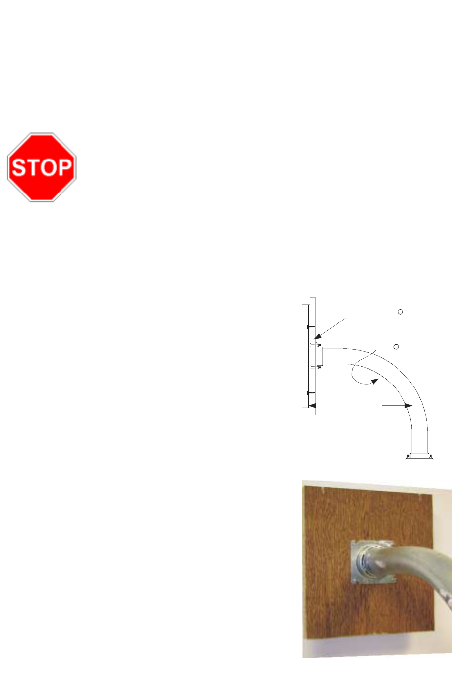
PEDESTAL-MOUNTING
INSTRUCTIONS:
There must be no conducting metal closer
than 10 inches to the DR4220 reader, ex-
cept for a unit mounted with a goose-neck
pedestal mounting tube, as shown in figure 1.
The recommended mounting methods follow:
1. Remove the case front (cover).
2. Use the NexWatch-supplied drilling tem-
plate to pre-drill 4 holes on the plywood
or LEXAN®sheet (recommended ¾" thick).
A channel must be cut into the plywood
or LEXAN®for the cable between the exit
point of the reader and the goose-neck.
3. Mount the plywood or LEXAN®sheet to a
goose-neck pedestal mounting tube. (A
minimum of 10" clearance is recommended
between the back of the reader and the
vertical metal tubing). Center the mounting
tube. (See figures 1 and 2.)
Figure 2
3/4" Plywood or Lexan Sheet
10” Minimum
Clearance Between
Back of Reader and
Vertical Metal Tubing
Goose-Neck Assembly Mounted to
Lexan /Plywood
in Middle of
Transmit
Coil
Figure 1
R
R
P/N 7-600033 Rev. F2 ©Honeywell International. All Rights Reserved.
DigiReader DR4220 Installation Notes
4. See the INTERNAL INTERFACE CABLE
sectiononpage1toinstallthecolor-
coded pigtail cable.
5. Route the cable through a channel on the
plywood or LEXAN®sheet. (See page 4:
RECOMMENDED STAND-OFF PLATE.)
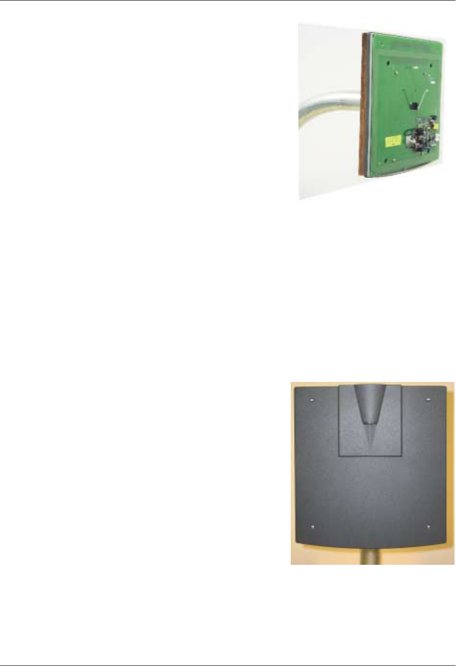
6. Mount the DR4220 board and case back
(back plate) to the plywood or LEXAN®
sheet which is securely attached to the
goose-neck as shown in figure 3.
7. Set the address switch, as required.
8. Install the case front (cover) and be sure
that the LED is not damaged as it enters
the lens assembly.
9. Secure the case front four holes with the
supplied screws. (See figure 4.)
WALL-MOUNTING INSTRUCTIONS:
There must be no conducting metal closer than 10 inches to the DR4220 reader.
The recommended mounting methods follow:
1. Remove the case front (cover).
2. Use the NexWatch-supplied drilling temp-
late (included with reader) to drill four
holes in the wall.
3. Follow the INTERNAL INTERFACE CABLE
instructions to install the pigtail cable.
(See page 1.)
4. Mount the DR4220 board and case back
(back plate) using 2¼" Panhead #6-32
thread screws (or other means approp-
riate to the wall composition).
5. Set the address switch, as required.
6. Install the case front (cover) and be sure
that the LED is not damaged as it enters
the lens assembly.
7. Secure the case front four holes with the
supplied screws. (See figure 4.)
Figure 4
Figure 3
P/N 7-600033 Rev. F3 ©Honeywell International. All Rights Reserved.
DigiReader DR4220 Installation Notes
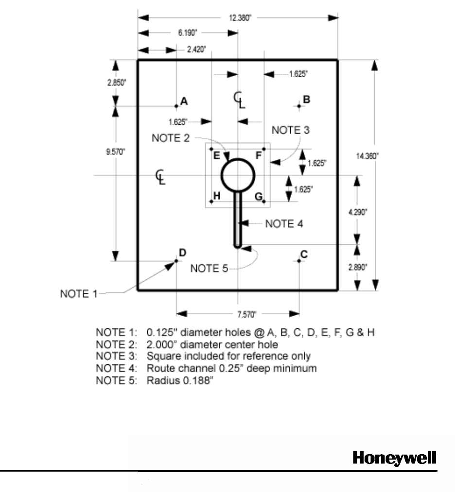
RECOMMENDED STAND-OFF PLATE
Material is 3/4” LEXAN®, plywood or equivalent.
LEXAN® is a Registered Trademark of General Electric Corporation.
Specifications subject to change without notice.
© Honeywell International. All rights reserved.
Document 7-600033, Revision F
Honeywell
135 West Forest Hill Avenue
Oak Creek, WI 53154
(414) 766-1700 Ph
(414) 766-1798 Fax
www.honeywell.com
Honeywell – Europe
Boeblingerstrasse 17
71101 Schonaich
Germany