Honeywell 1981A Barcode Scanner User Manual 14C0587R 1981i 1 2015 02 10
Honeywell International Inc Barcode Scanner 14C0587R 1981i 1 2015 02 10
Contents
- 1. 14C0587R-1981i-User Manual-1-2015-02-10
- 2. 14C0587R-1981i-User Manual-2-2015-02-10
- 3. 14C0587R-1981i-User Manual-3-2015-02-10
14C0587R-1981i-User Manual-1-2015-02-10
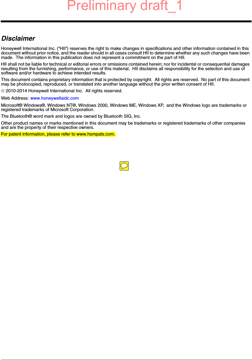
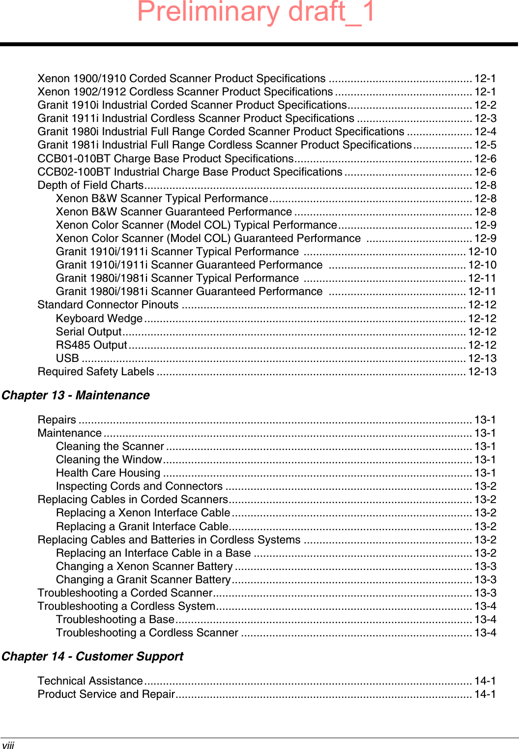

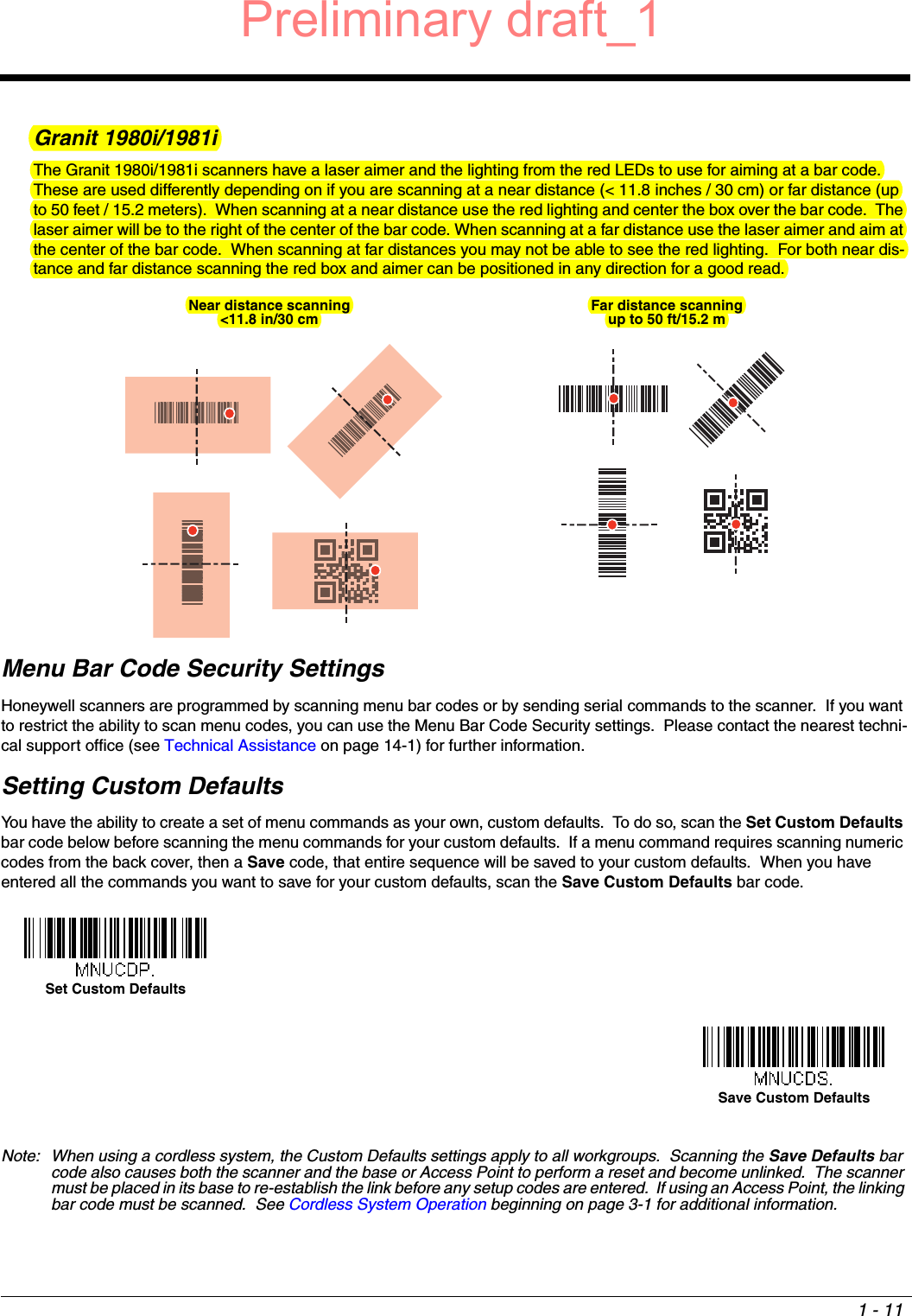
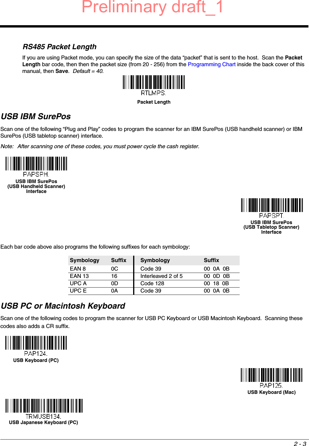
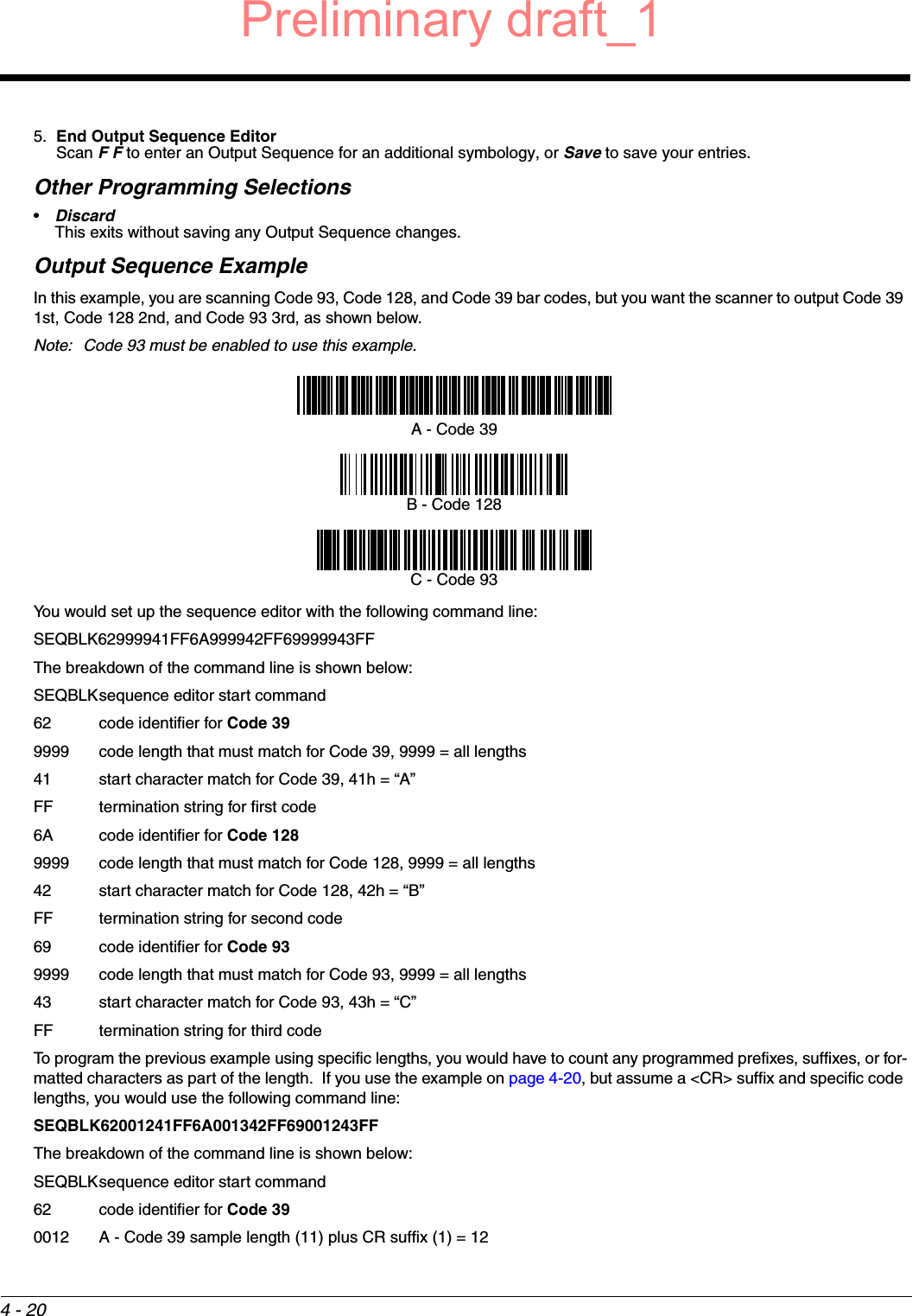
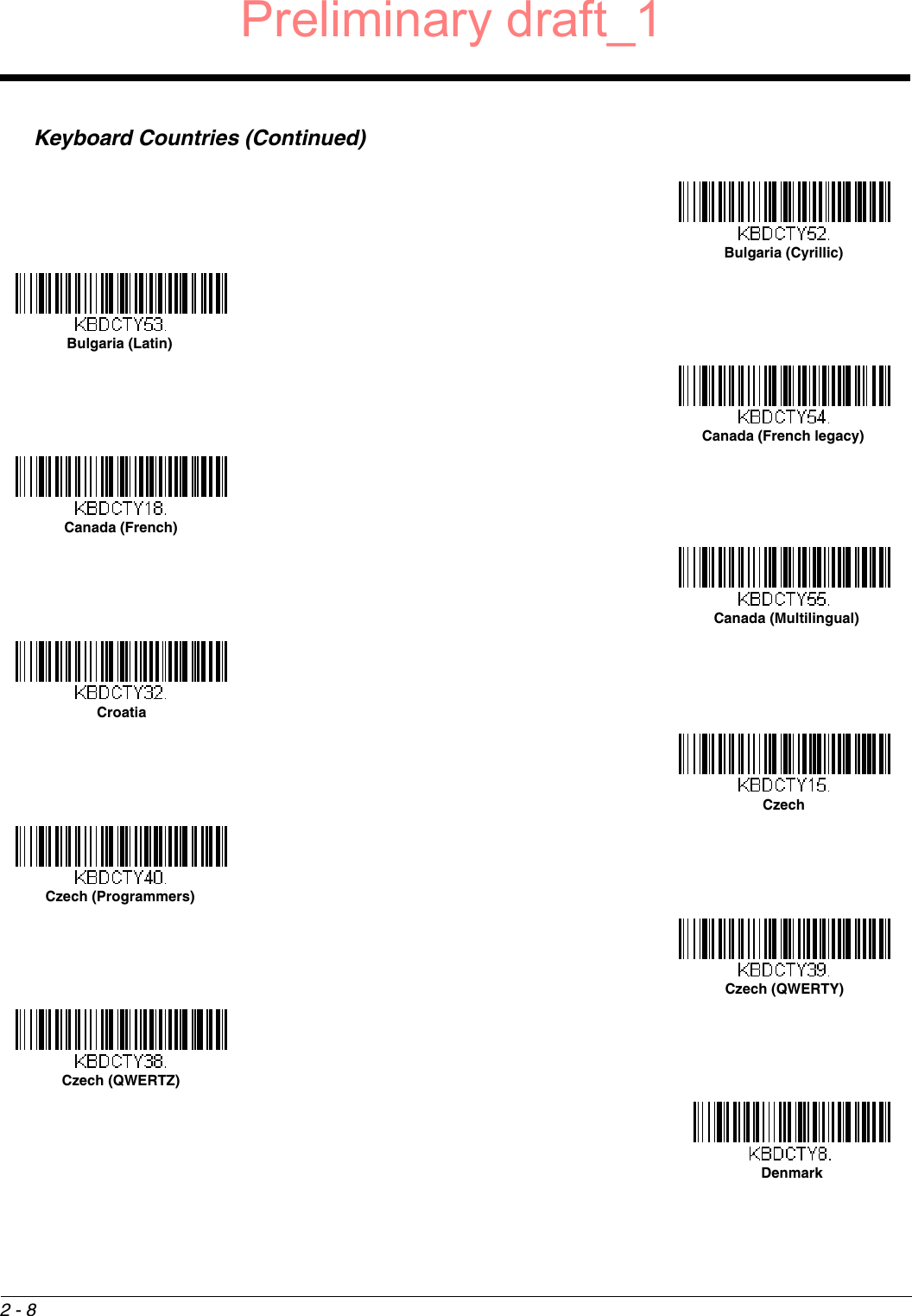
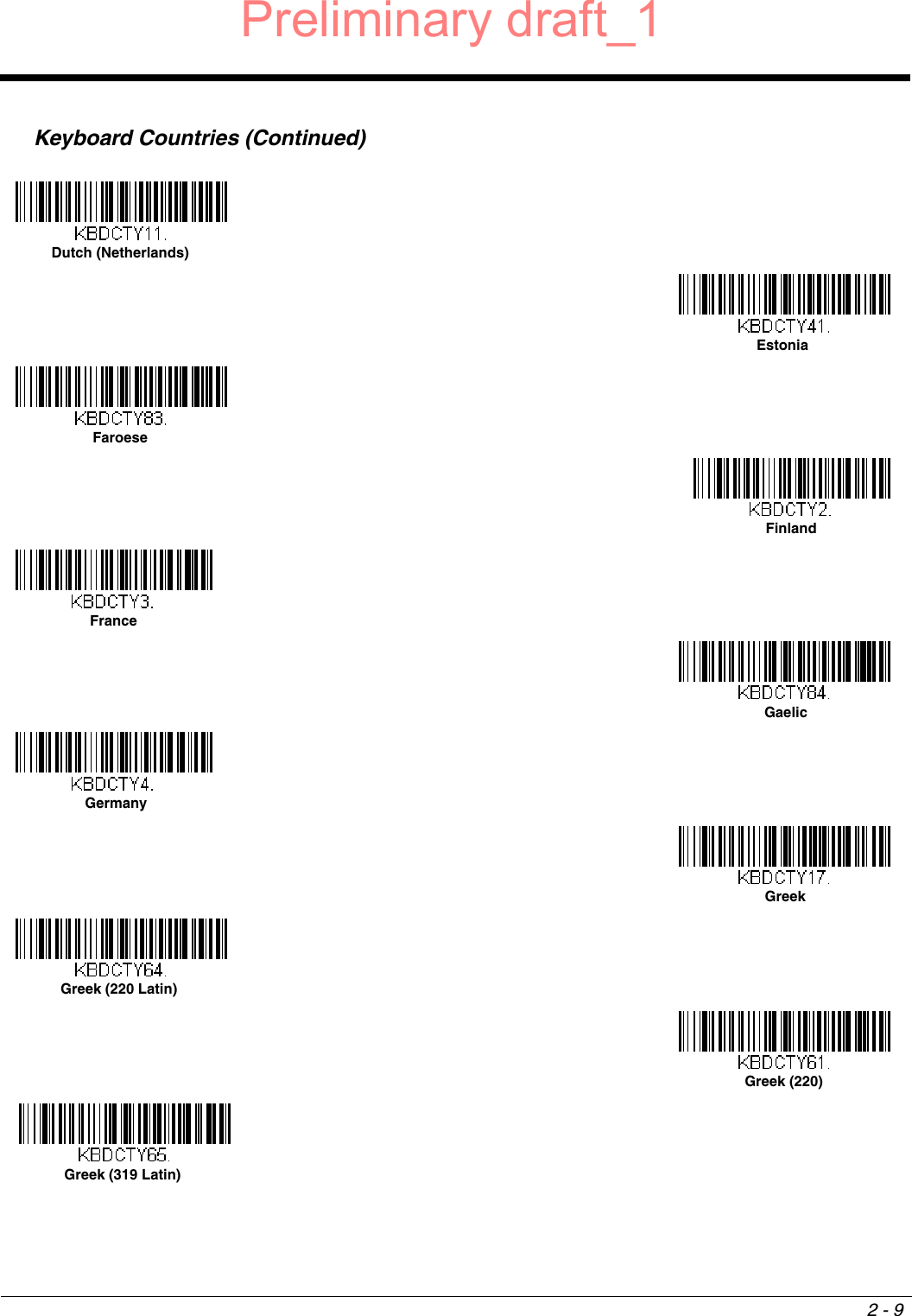
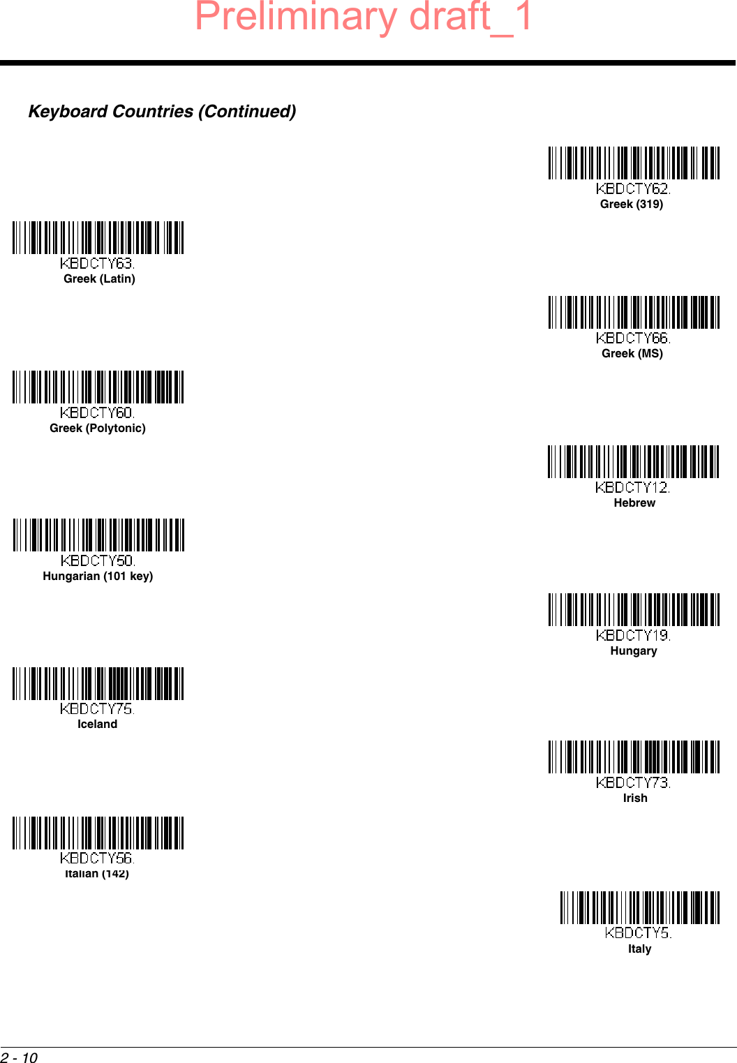
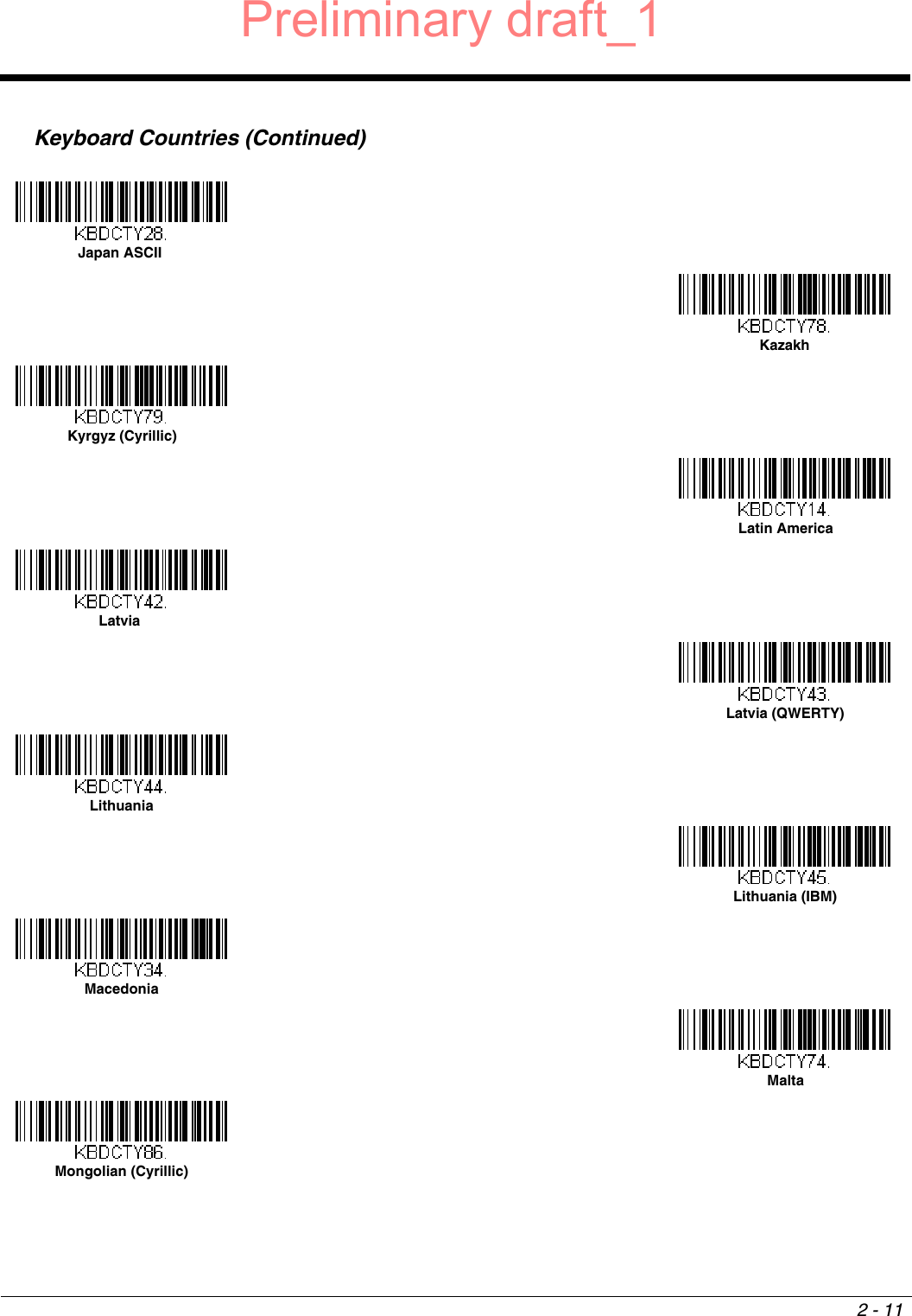
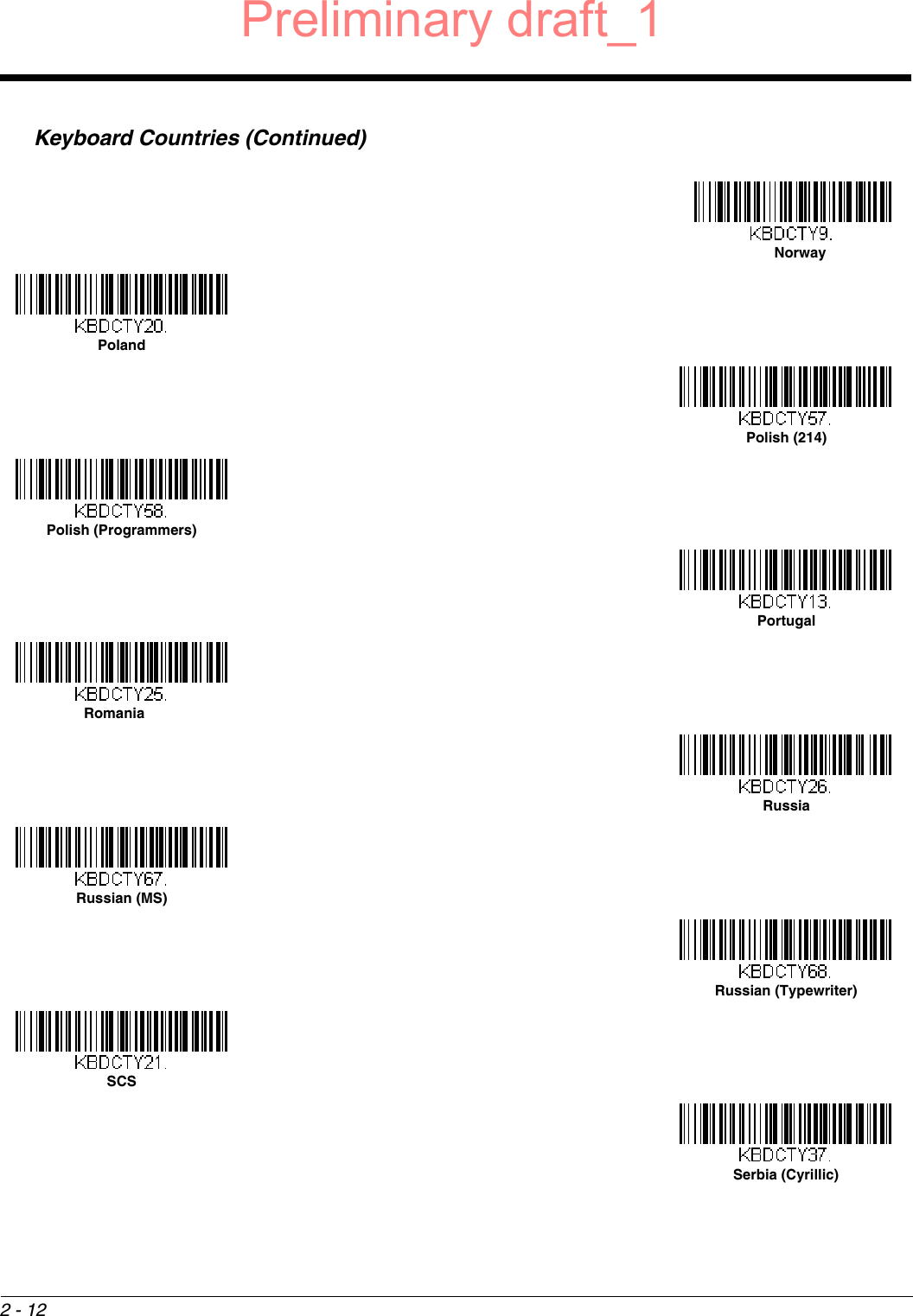
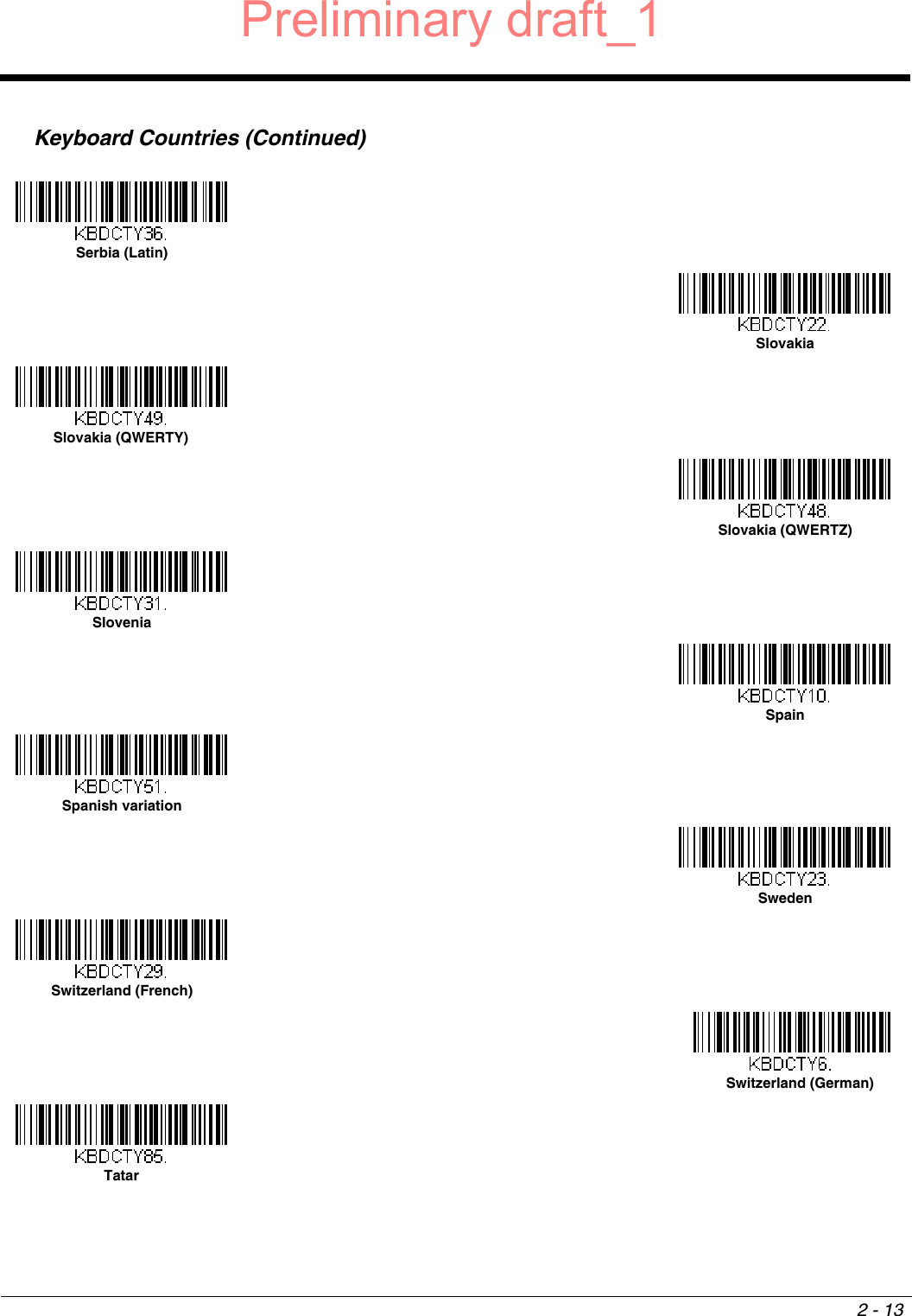
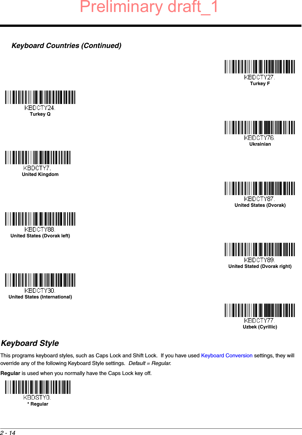
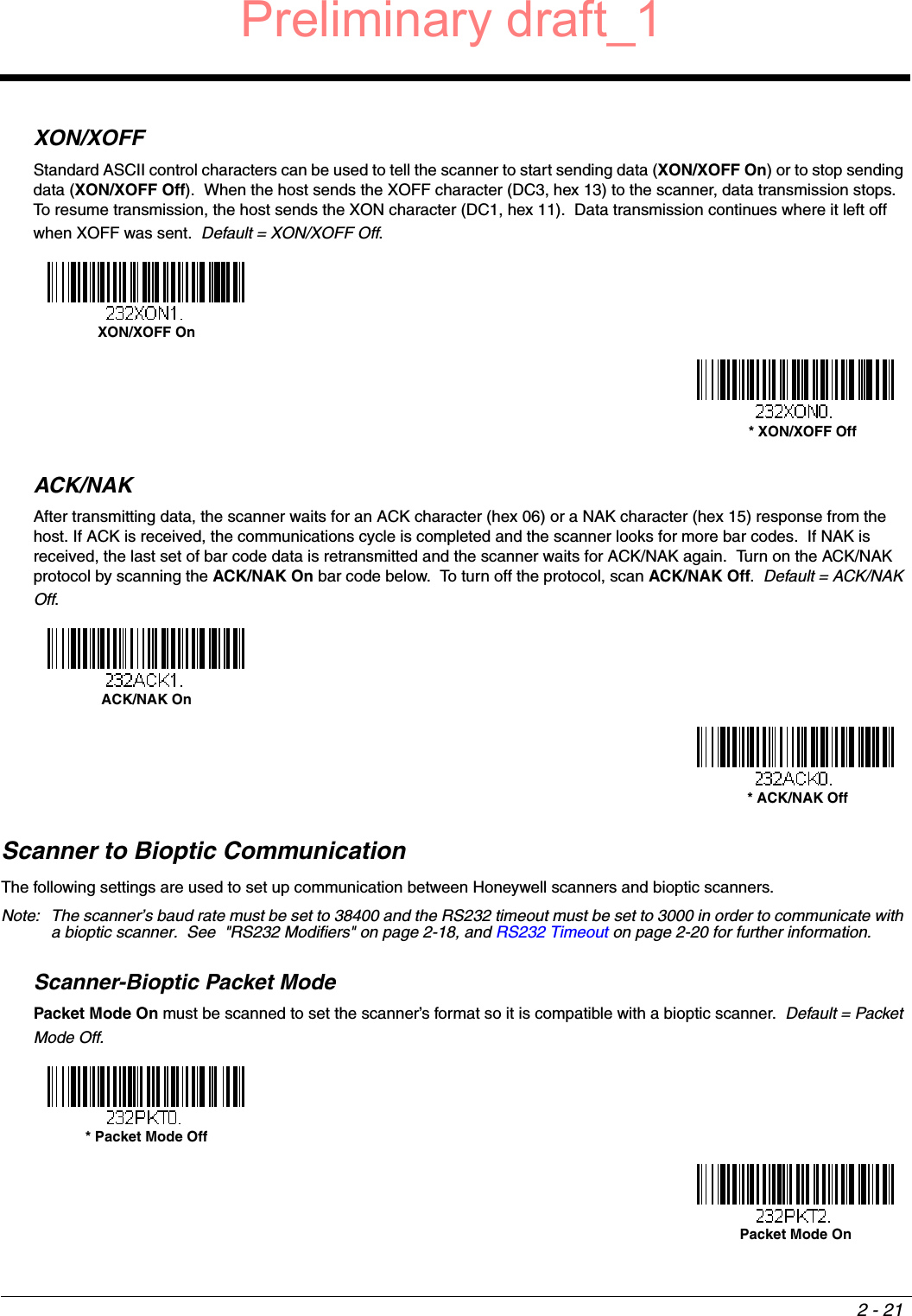
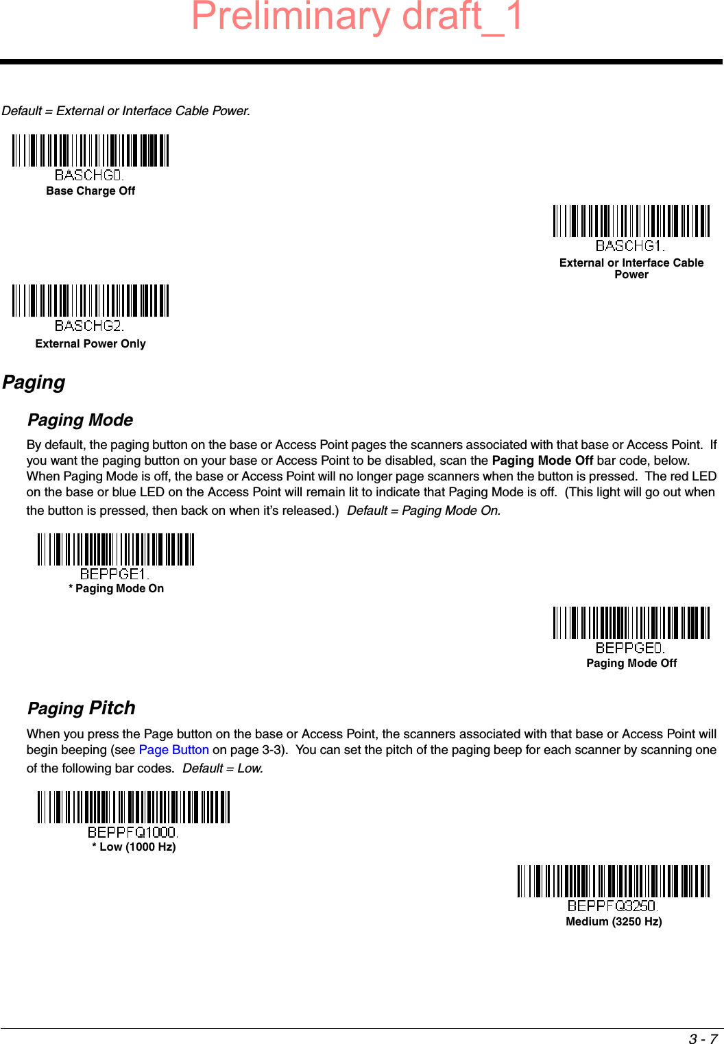
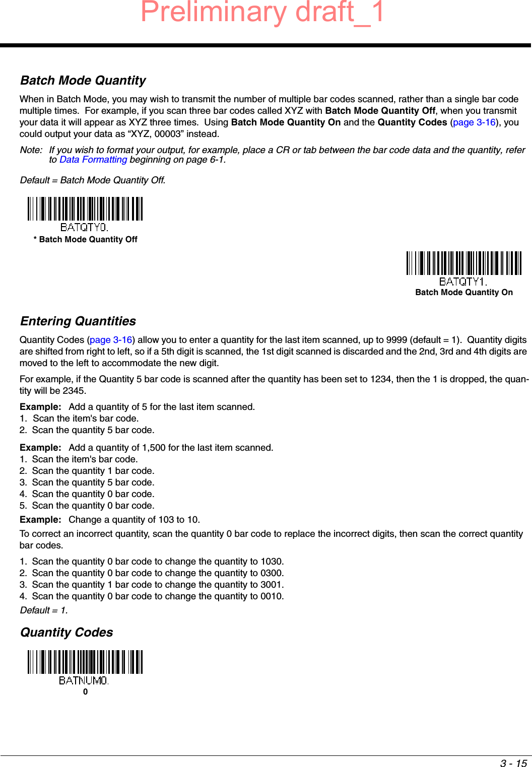
![2 - 7Keyboard Country LayoutScan the appropriate country code below to program the keyboard layout for your country or language. As a general rule, the following characters are supported, but need special care for countries other than the United States:@ | $ # { } [ ] = / ‘ \ < > ~ Keyboard CountriesWincor Nixdorf Beetle Settings* United States AlbaniaAzeri (Cyrillic)Azeri (Latin)BelarusBelgiumBosniaBrazilBrazil (MS)Preliminary draft_1](https://usermanual.wiki/Honeywell/1981A.14C0587R-1981i-User-Manual-1-2015-02-10/User-Guide-2529867-Page-31.png)
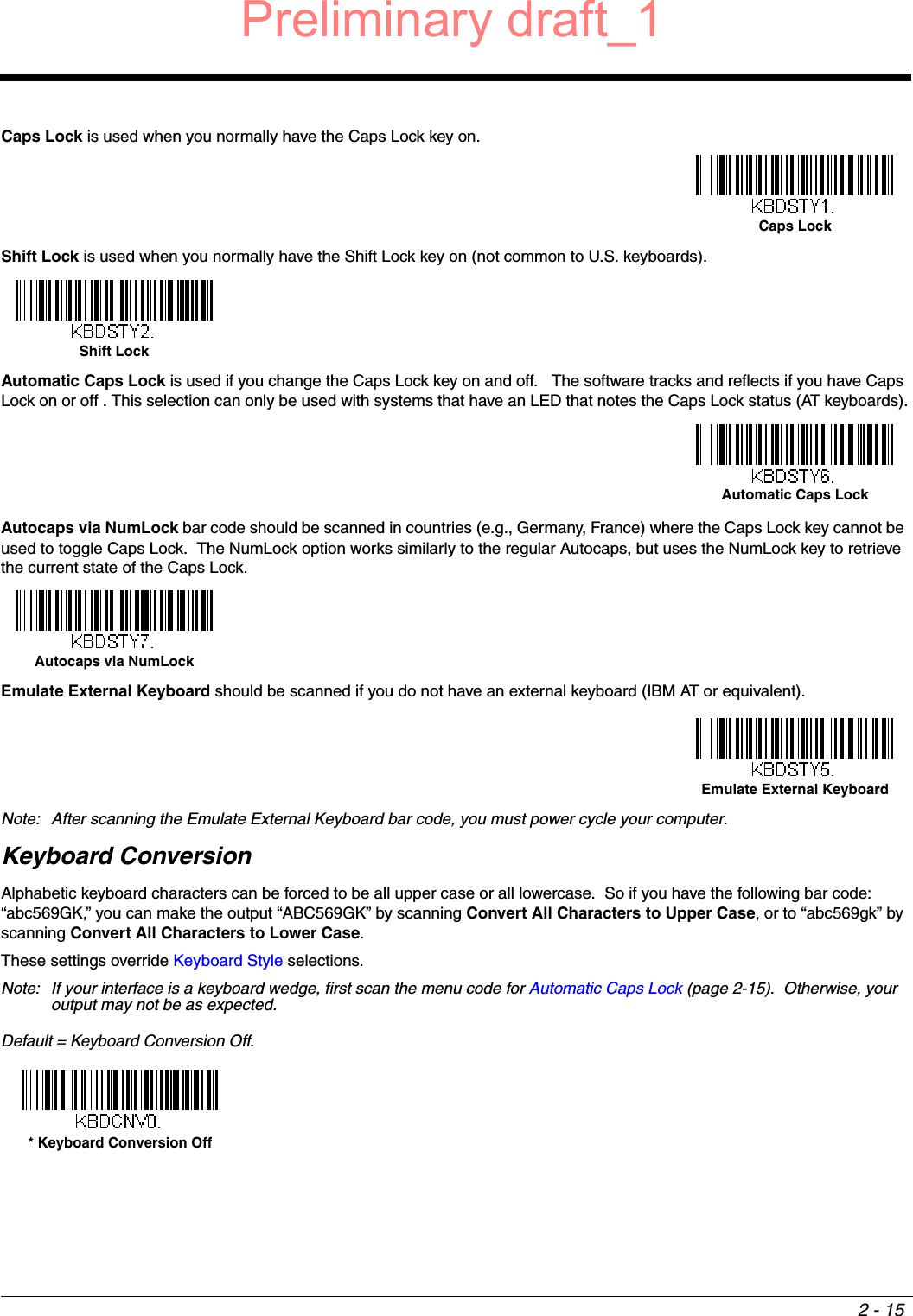
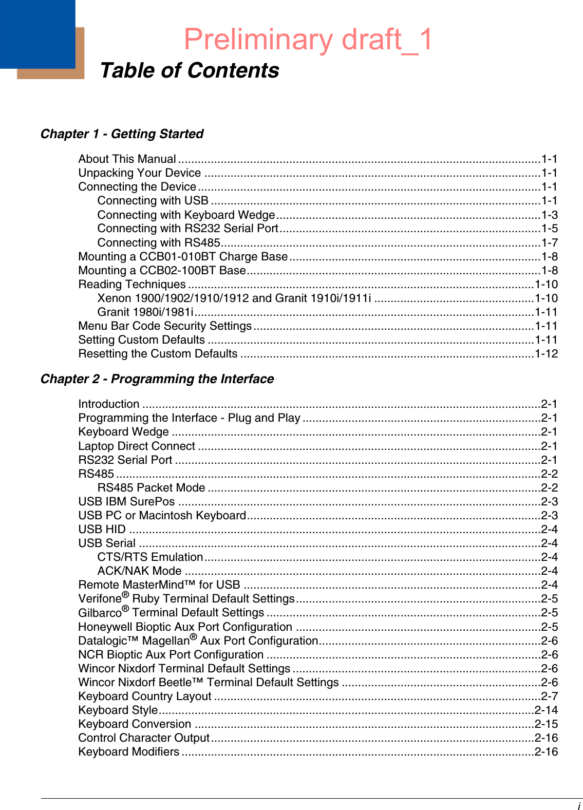
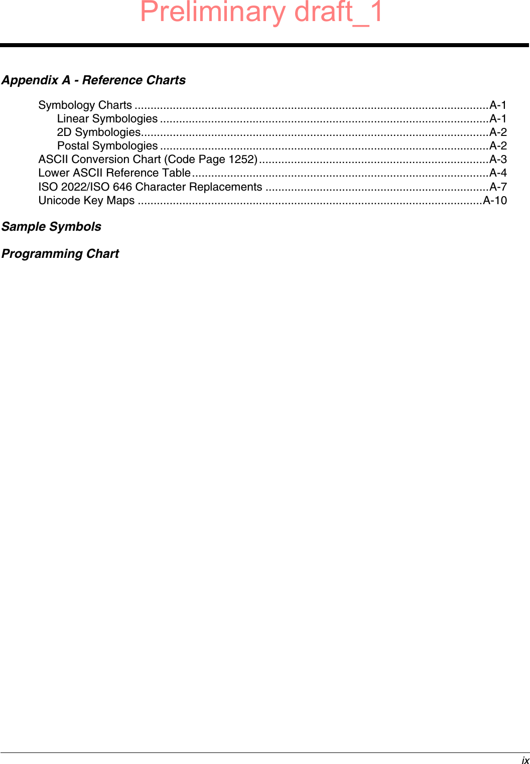
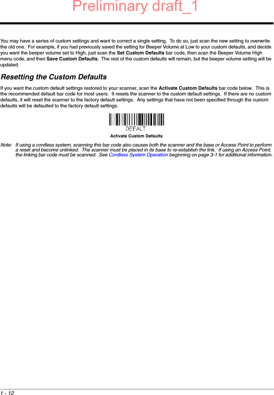
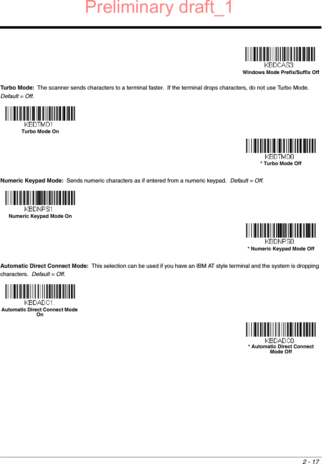
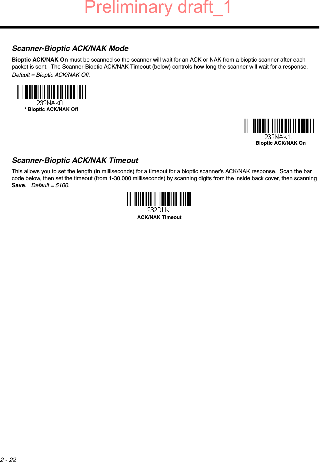
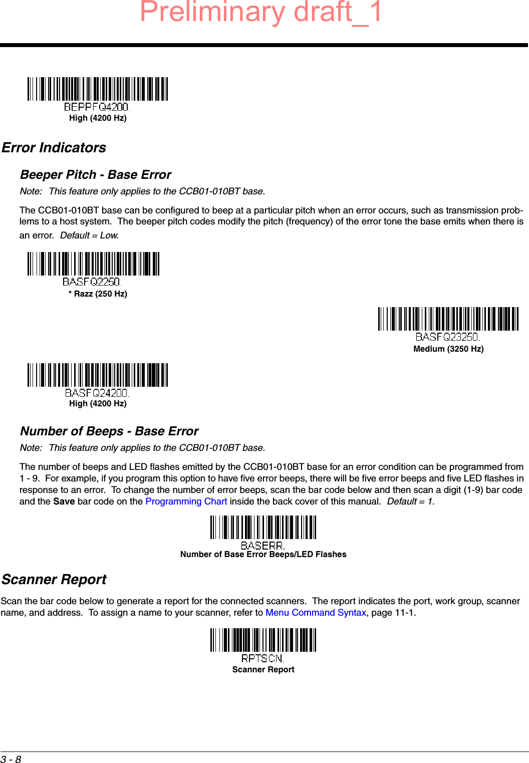
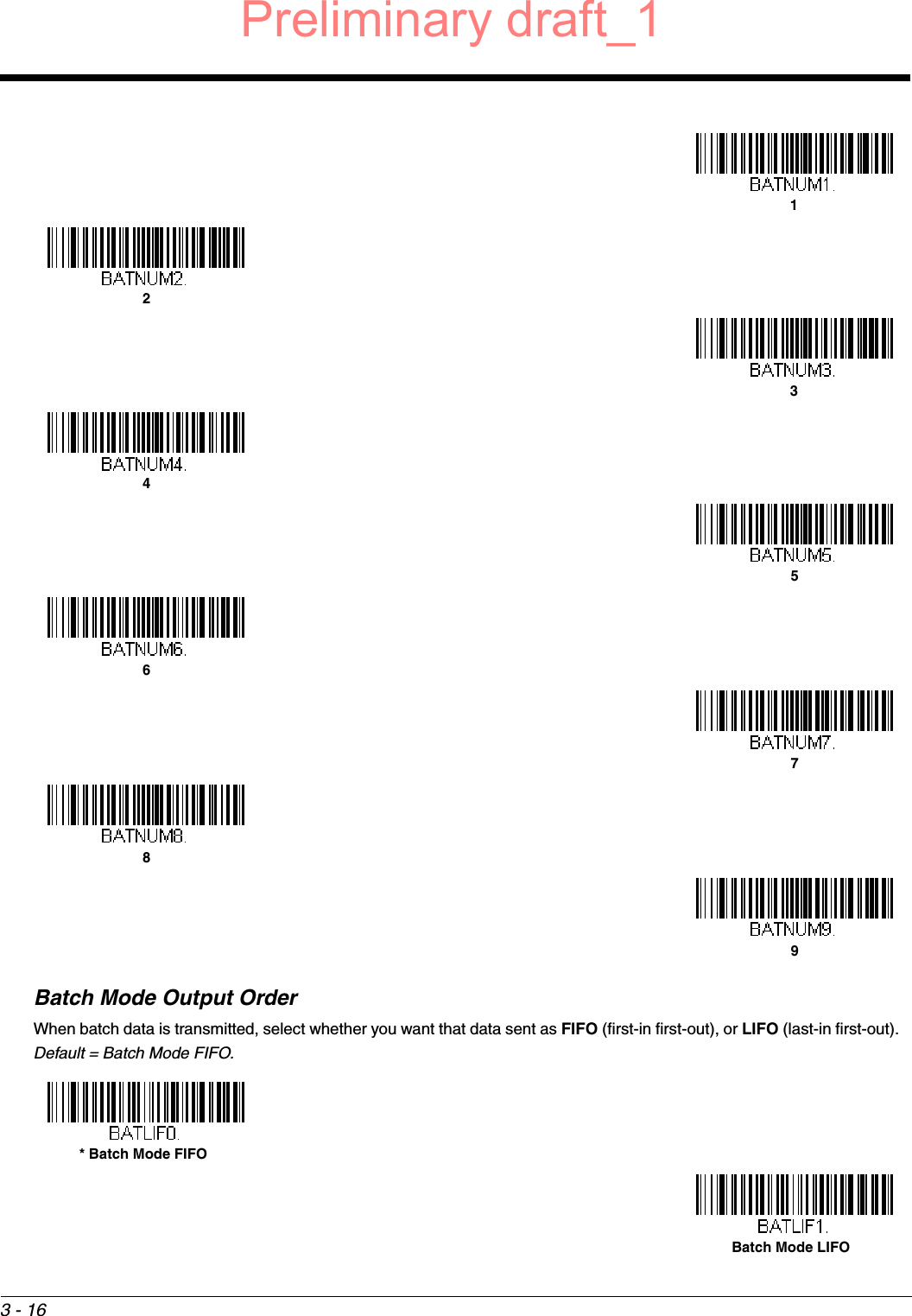
![2 - 16Control Character OutputThis selection sends a text string instead of a control character. For example, when the control character for a carriage return is expected, the output would display [CR] instead of the ASCII code of 0D. Refer to ASCII Conversion Chart (Code Page 1252) on page A-3. Only codes 00 through 1F are converted (the first column of the chart). Default = Off.Note: Control + X (Control + ASCII) Mode overrides this mode. Keyboard ModifiersThis modifies special keyboard features, such as CTRL+ ASCII codes and Turbo Mode.Control + X (Control + ASCII) Mode On: The scanner sends key combinations for ASCII control characters for values 00-1F. Windows is the preferred mode. All keyboard country codes are supported. DOS mode is a legacy mode, and it does not sup-port all keyboard country codes. New users should use the Windows mode. Refer to Keyboard Function Relationships, page 9-1 for CTRL+ X Values. Windows Mode Prefix/Suffix Off: The scanner sends key combinations for ASCII control characters for values 00-1F, but it does not translate prefix or suffix information. Default = Control + X Mode Off.Convert All Characters to Upper CaseConvert All Characters to Lower CaseControl Character Output On* Control Character Output OffWindows Mode Control + X Mode On * Control + X Mode Off DOS Mode Control + X Mode On Preliminary draft_1](https://usermanual.wiki/Honeywell/1981A.14C0587R-1981i-User-Manual-1-2015-02-10/User-Guide-2529867-Page-40.png)
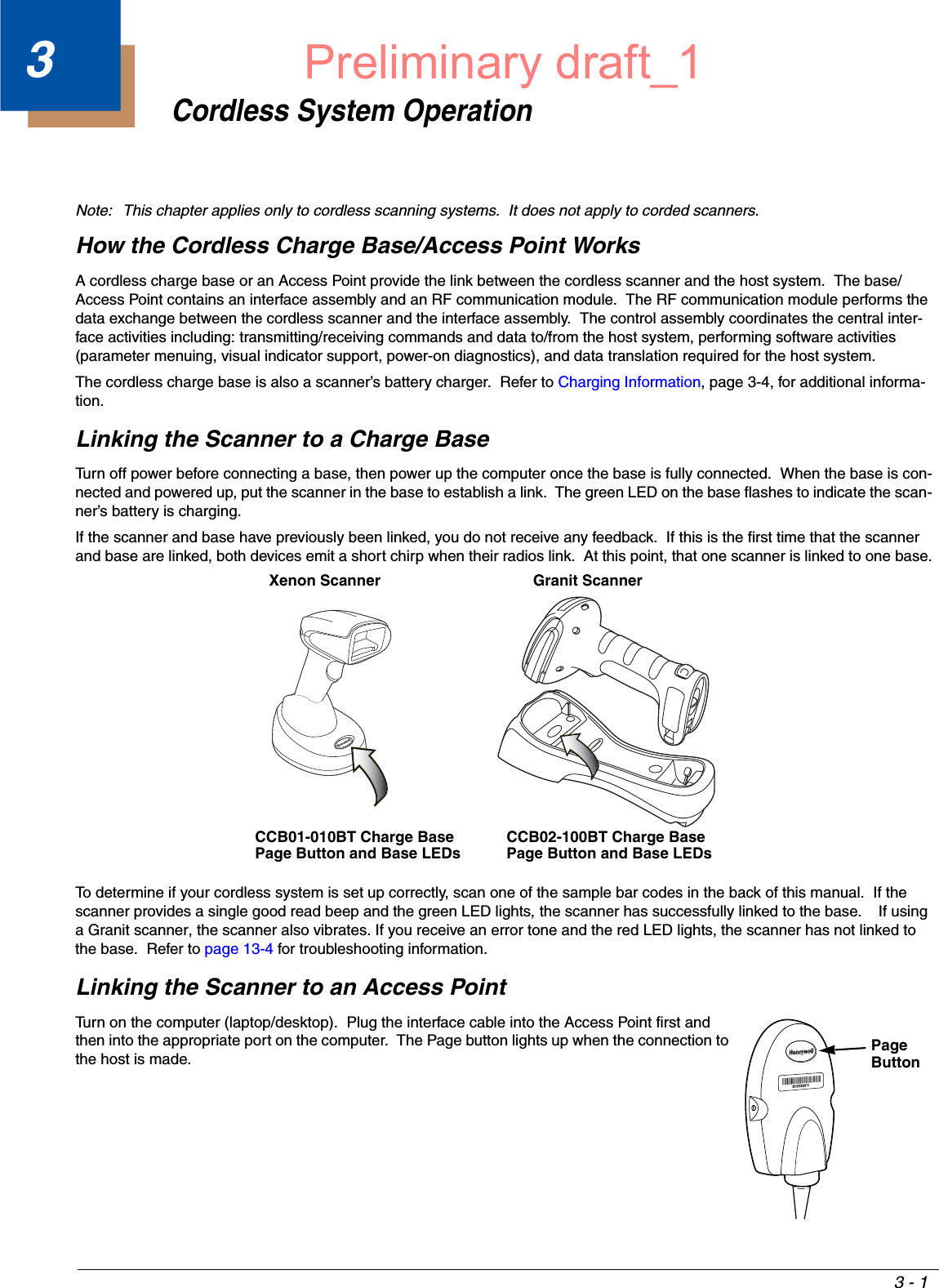
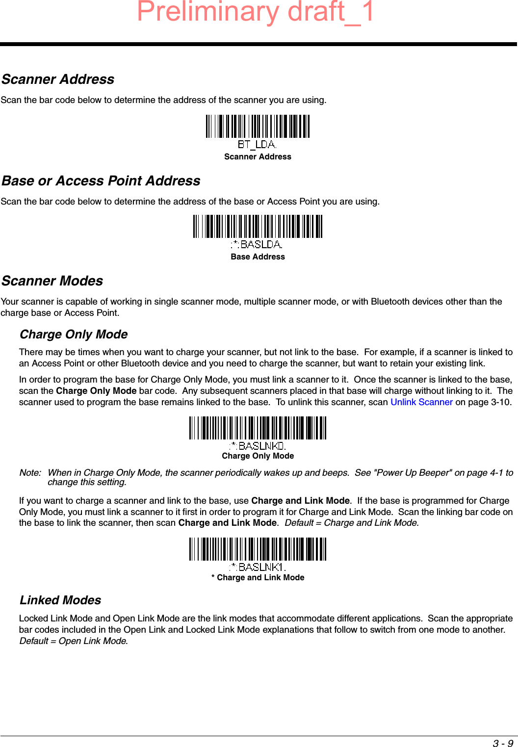
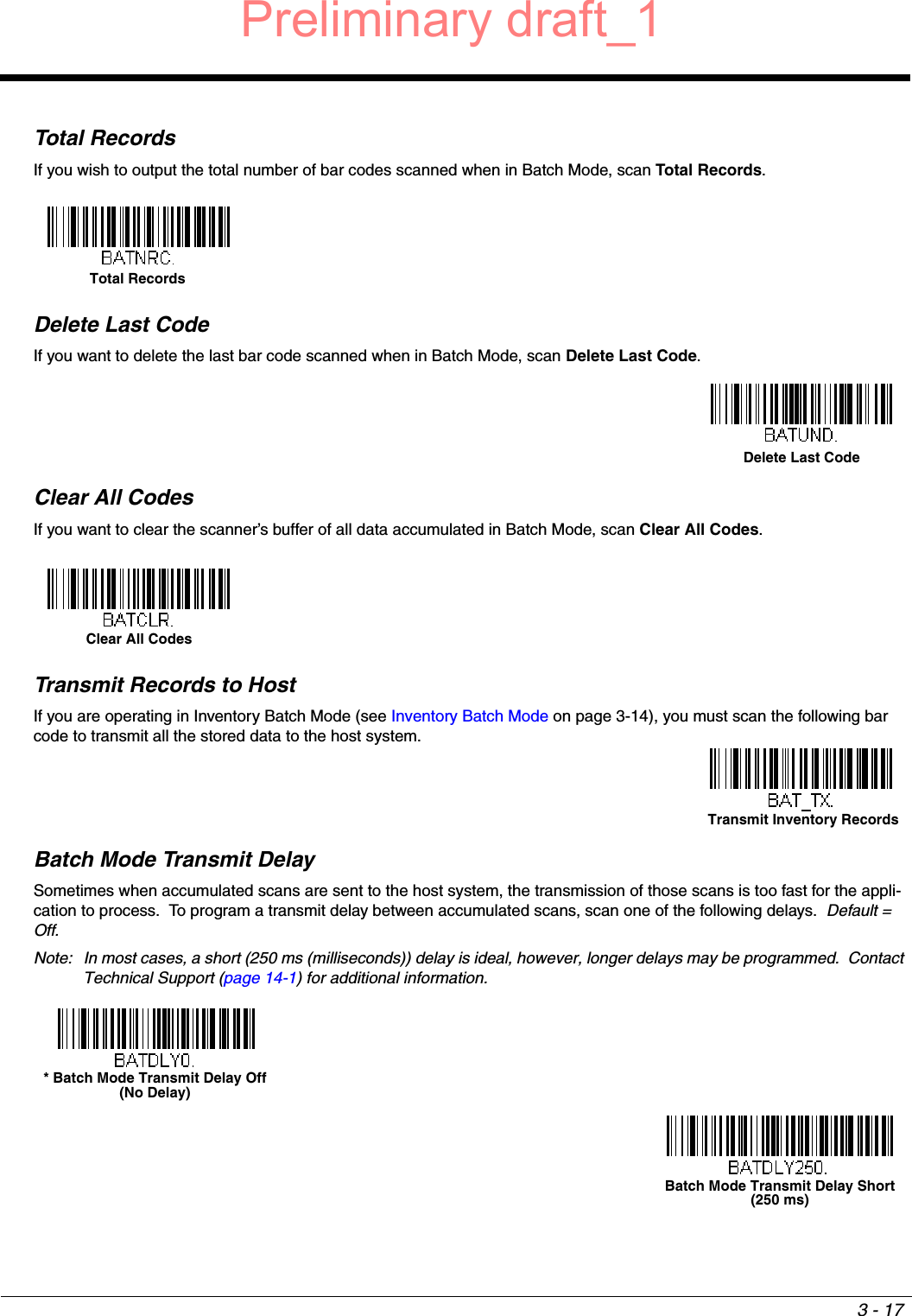
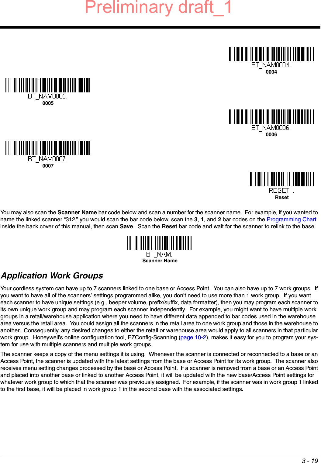
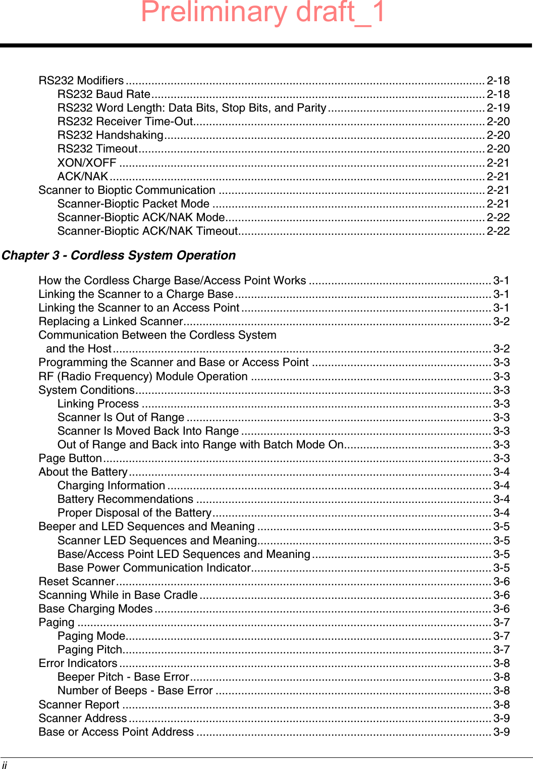
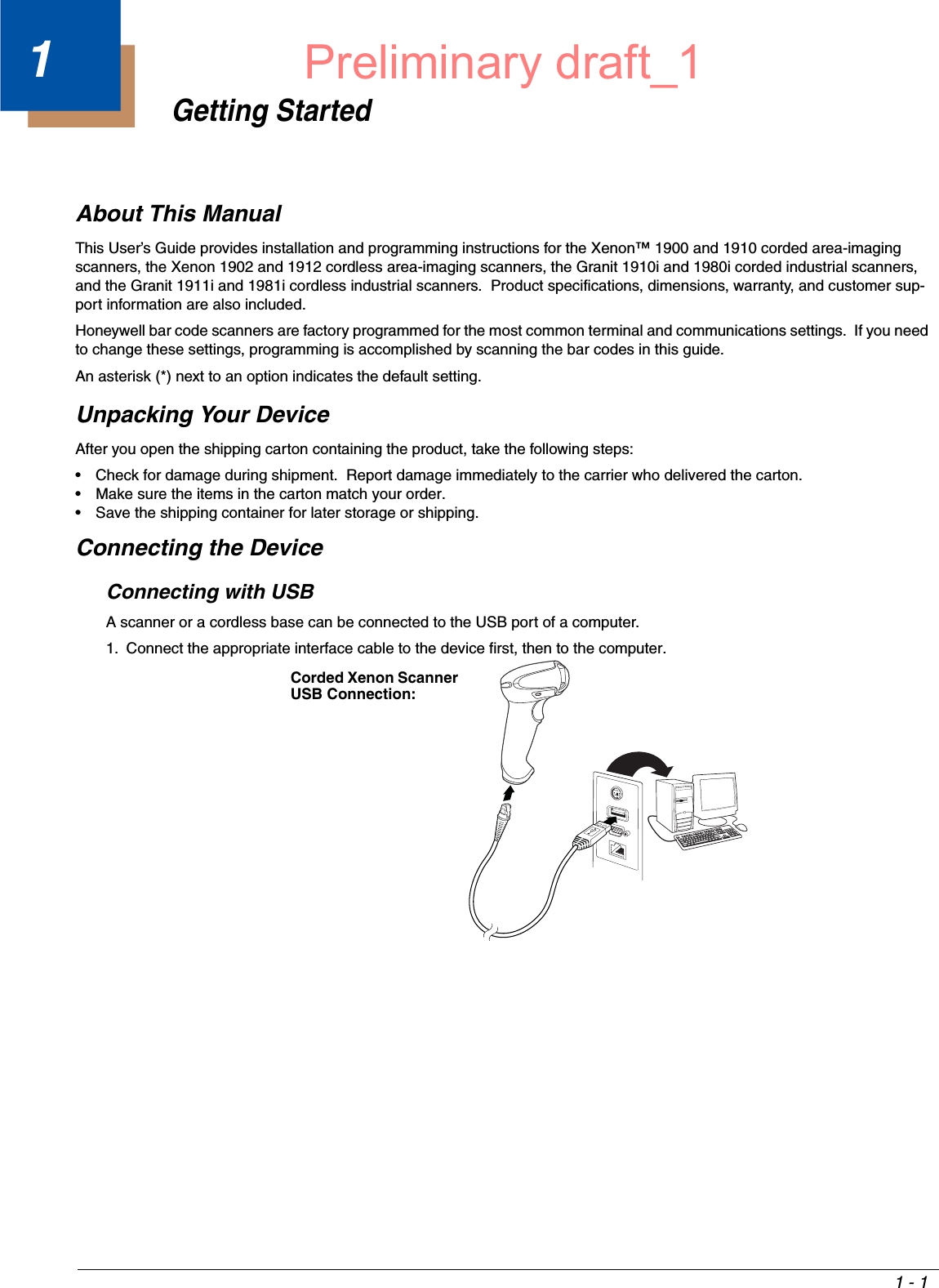
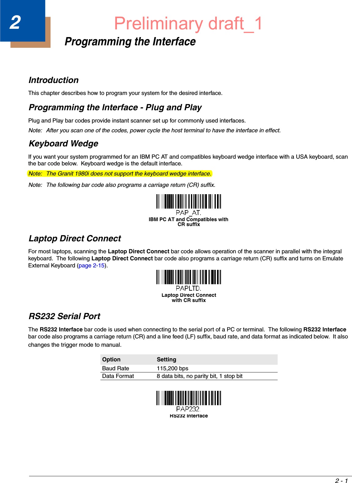
![3 - 26Host AcknowledgmentSome applications require that the host terminal (or server) validate incoming bar code data (database look-up) and provide acknowledgement to the scanner whether or not to proceed. In Host ACK Mode, the scanner waits for this acknowledgement after each scan. Visual and audible acknowledgements provide valuable feedback to the scan operator. The Host ACK func-tionality is controlled via a number of pre-defined escape commands that are sent to the scanner to make it behave in different ways.Note: System performance degrades when using Host ACK at rates lower than 9600 baud.The following criteria must be met for the Host ACK to work correctly:• The cordless system must be configured for Host Port RS232 (terminal ID = 000) or USB COM Emulation (terminal ID = 130).• RTS/CTS is defaulted off. You must enable it if the host system requires it.• Host ACK must be set to On (page 3-27). • A comma must be used as a terminator.• The host terminal software must be capable of interpreting the bar code data, make decisions based on the data content, and send out appropriate escape commands to the scanner.Escape commands are addressed to the scanner via “Application Work Groups.” Once a command is sent, all scanners in a group respond to that command. Because of this, it is recommended that each scanner is assigned to its own group in Host ACK mode.The commands to which the scanner responds are listed on page 3-27. The [ESC] is a 1B in hex. A typical command string is y [ESC] x, where “y” is the application work group number, “[ESC] x” is the escape command, and the comma is the terminator, which is required. (When “y” is not specified, the command is sent to the default Application Work Group 0.)Example: Commands may be strung together to create custom response sequences. An example of a command string is listed below.0[ESC]4,[ESC]5,[ESC]6,The above example will make a scanner that is in application work group zero beep low, then medium, then high.Example: A good read beep is required for any item on file, but a razz or error tone is required if the item is not on file. In this case,[ESC]7, is sent to the host for an on-file product[ESC]8,[ESC]8, is sent to the host for a not-on-file productWhen a bar code is scanned, the scanner enters a timeout period until either the host ACK sequence is received, or the timeout expires (in 10 seconds, by default).Once Host ACK is enabled, the system works as follows when a bar code is scanned:• The scanner reads the code and sends data to the base or Access Point to transmit to the host system. No audible or visual indication is emitted until the scanner receives an escape command. The scanner read illumination goes out when there’s a successful read.• Scanner operation is suspended until 1) a valid escape string is received from the host system or 2) the scanner times out.• Once condition 1 or 2 above has been met, the scanner is ready to scan again, and the process repeats.A time-out occurs if the scanner does not receive a valid escape command within 10 seconds. A time-out is indicated by an error tone. If a time-out occurs, the operator should check the host system to understand why a response to the scanner was not received.Preliminary draft_1](https://usermanual.wiki/Honeywell/1981A.14C0587R-1981i-User-Manual-1-2015-02-10/User-Guide-2529867-Page-72.png)
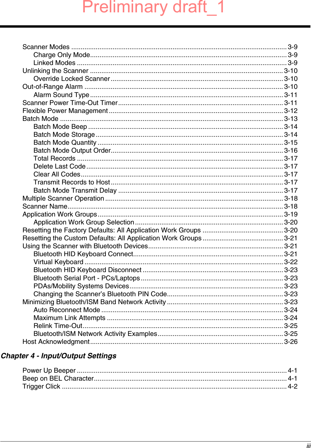
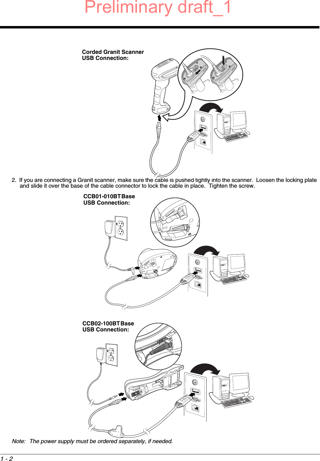
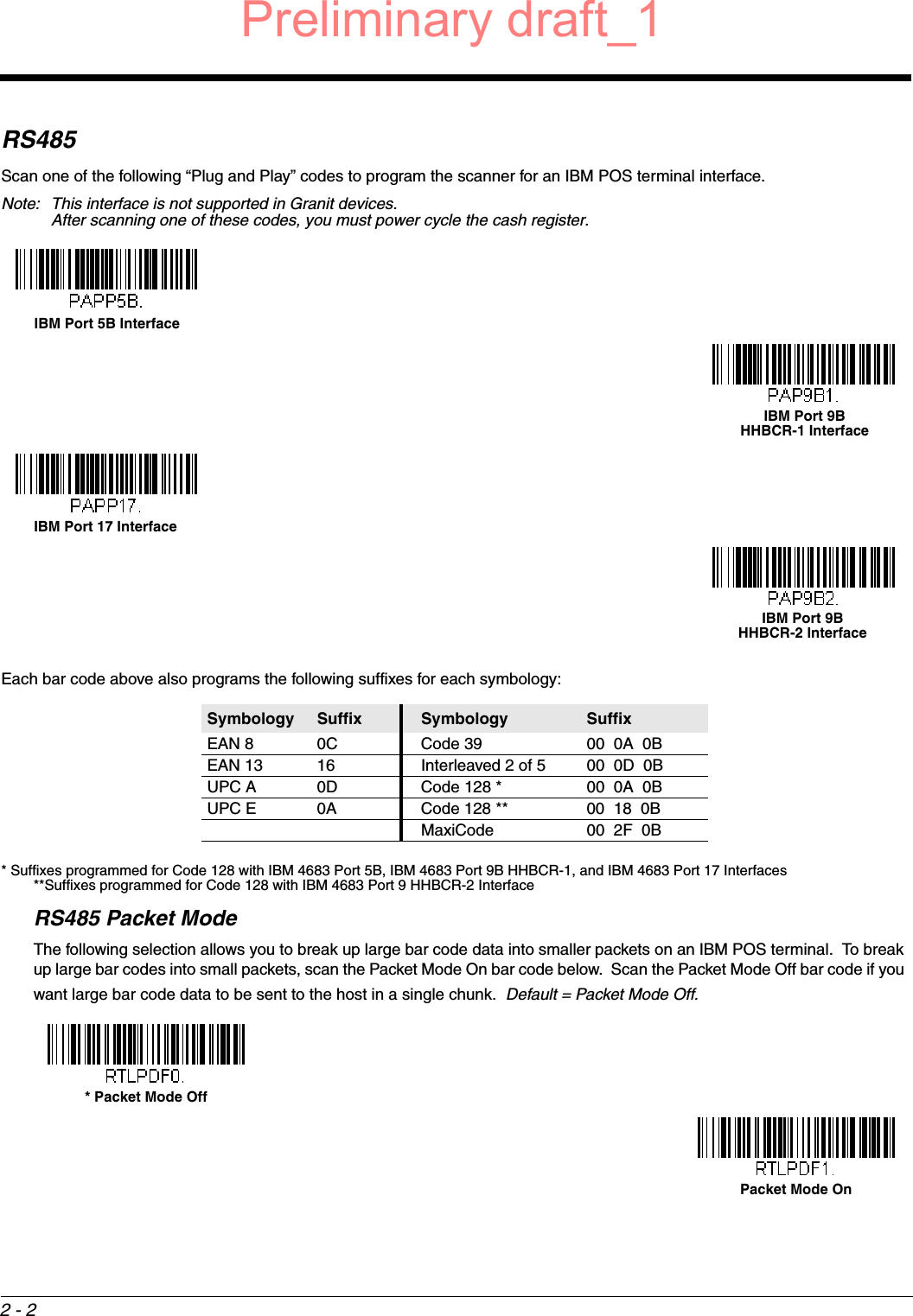
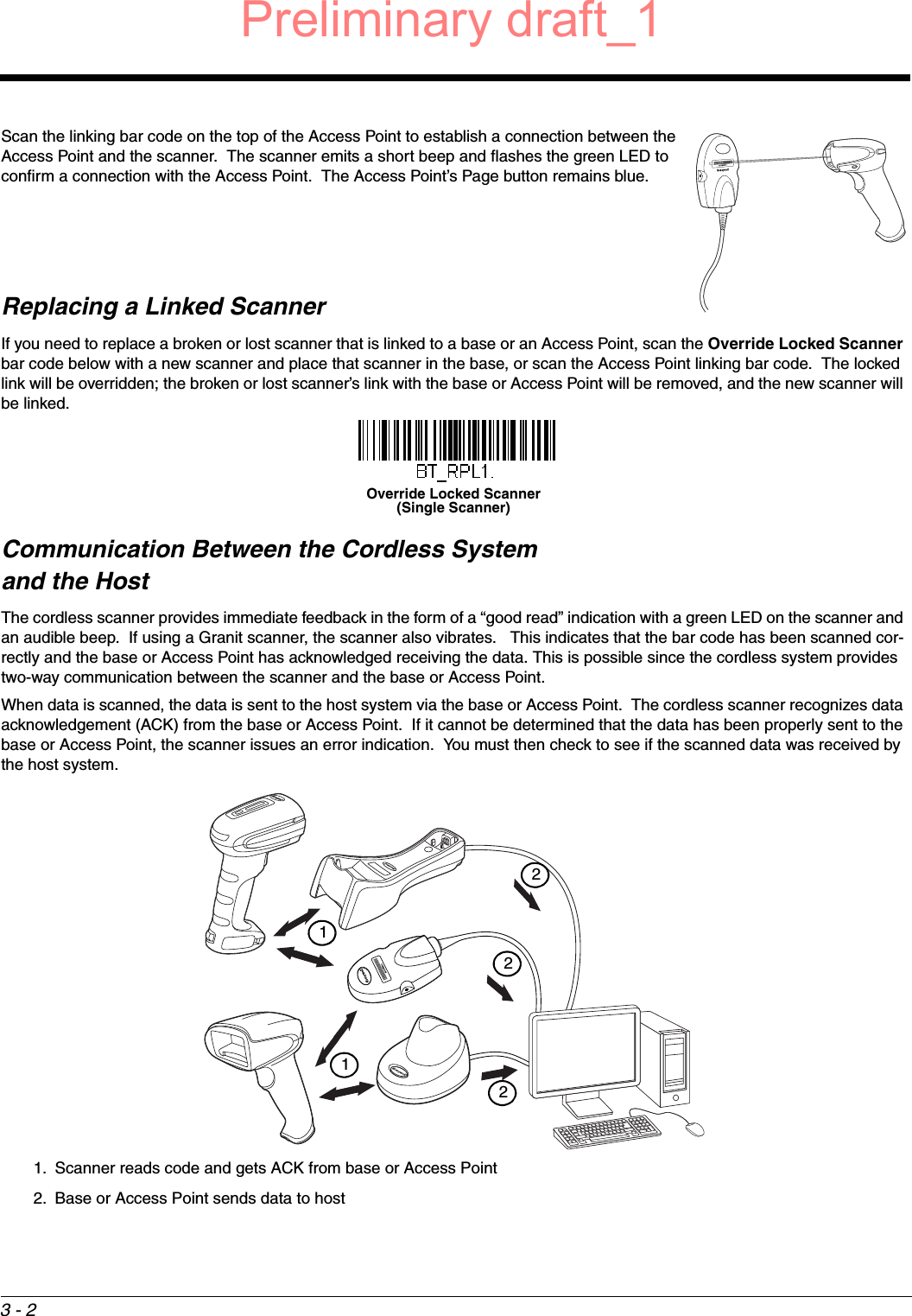
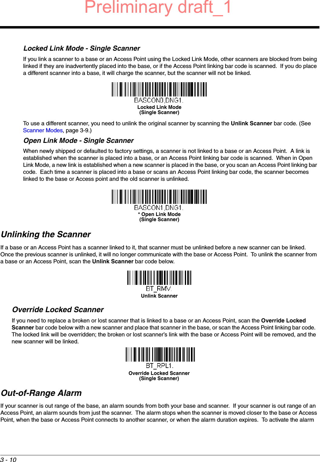
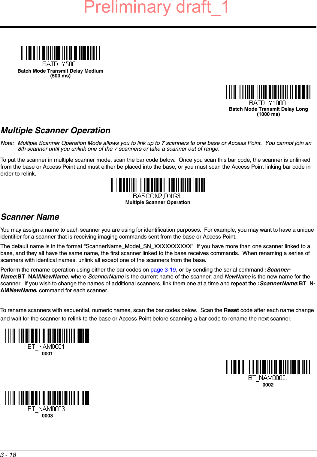
![3 - 27Host ACK On/OffHost ACK ResponsesCommand Action[ESC] a, Double beeps to indicate a successful menu change was made.[ESC] b, Razz or error tone to indicate a menu change was unsuccessful.[ESC] 1, The green LED illuminates for 135 milliseconds followed by a pause.[ESC] 2, The green LED illuminates for 2 seconds followed by a pause.[ESC] 3, The green LED illuminates for 5 seconds followed by a pause.[ESC] 4, Emits a beep at a low pitch.[ESC] 5, Emits a beep at a medium pitch.[ESC] 6, Emits a beep at a high pitch.[ESC] 7, Beeps to indicate a successful decode and communication to host. [ESC] 8,[ESC] 8, Razz or error tone to indicate a decode/communication to host was unsuccessful.Host ACK On* Host ACK OffPreliminary draft_1](https://usermanual.wiki/Honeywell/1981A.14C0587R-1981i-User-Manual-1-2015-02-10/User-Guide-2529867-Page-73.png)

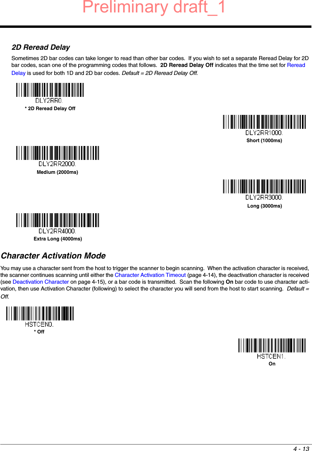
![4 - 14Activation CharacterThis sets the character used to trigger scanning when using Character Activation Mode. On the ASCII Conversion Chart (Code Page 1252), page A-3, find the hex value that represents the character you want to use to trigger scanning. Scan the following bar code, then use the Programming Chart to read the alphanumeric combination that represents that ASCII character. Scan Save to finish. Default = 12 [DC2].End Character Activation After Good ReadAfter a bar code is successfully detected and read from the scanner, the illumination can be programmed either to remain on and scanning, or to turn off. When End Character Activation After Good Read is enabled, the illumination turns off and stops scanning after a good read. If you scan Do Not End Character Activation After Good Read, the illumination remains on after a good read. Default = Do Not End Character Activation After Good Read.Character Activation TimeoutYou can set a timeout for the length of time the illumination remains on and attempting to decode bar codes when using Character Activation Mode. Set the length (in milliseconds) for a timeout by scanning the following bar code, then setting the timeout (from 1-300,000 milliseconds) by scanning digits from the Programming Chart inside the back cover of this manual, then scanning Save. Default = 30,000 ms.Character Deactivation ModeIf you have sent a character from the host to trigger the scanner to begin scanning, you can also send a deactivation character to stop scanning. Scan the following On bar code to use character deactivation, then use Deactivation Character (following) to select the character you will send from the host to terminate scanning. Default = Off.Activation Character* Do Not End Character Activation After Good ReadEnd Character Activation After Good ReadCharacter Activation Timeout* OffPreliminary draft_1](https://usermanual.wiki/Honeywell/1981A.14C0587R-1981i-User-Manual-1-2015-02-10/User-Guide-2529867-Page-88.png)
![4 - 15Deactivation CharacterThis sets the character used to terminate scanning when using Character Deactivation Mode. On the ASCII Conversion Chart (Code Page 1252), page A-3, find the hex value that represents the character you want to use to terminate scanning. Scan the following bar code, then use the Programming Chart inside the back cover of this manual to read the alphanu-meric combination that represents that ASCII character. Scan Save to finish. Default = 14 [DC4].Illumination LightsIf you want the illumination lights on while reading a bar code, scan the Lights On bar code, below. However, if you want to turn just the lights off, scan the Lights Off bar code. Default = Lights On.Note: This setting does not affect the aimer light. The aiming light can be set using Aimer Mode (page 4-16). Aimer DelayThe aimer delay allows a delay time for the operator to aim the scanner before the picture is taken. Use these codes to set the time between when the trigger is pulled and when the picture is taken. During the delay time, the aiming light will appear, but the LEDs won’t turn on until the delay time is over. Default = Off.OnDeactivation Character* Lights OnLights Off200 milliseconds400 milliseconds* Off (no delay)Preliminary draft_1](https://usermanual.wiki/Honeywell/1981A.14C0587R-1981i-User-Manual-1-2015-02-10/User-Guide-2529867-Page-89.png)