Honeywell 1981A Barcode Scanner User Manual 14C0587R 1981i 2 2015 02 10
Honeywell International Inc Barcode Scanner 14C0587R 1981i 2 2015 02 10
Contents
- 1. 14C0587R-1981i-User Manual-1-2015-02-10
- 2. 14C0587R-1981i-User Manual-2-2015-02-10
- 3. 14C0587R-1981i-User Manual-3-2015-02-10
14C0587R-1981i-User Manual-2-2015-02-10
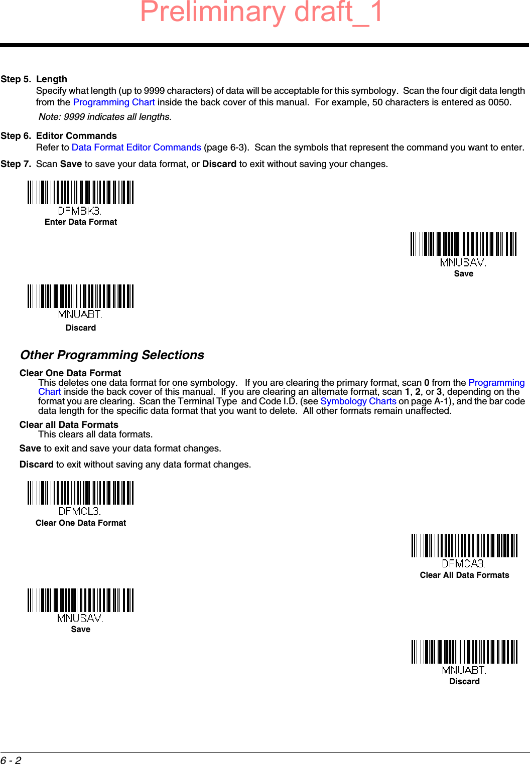
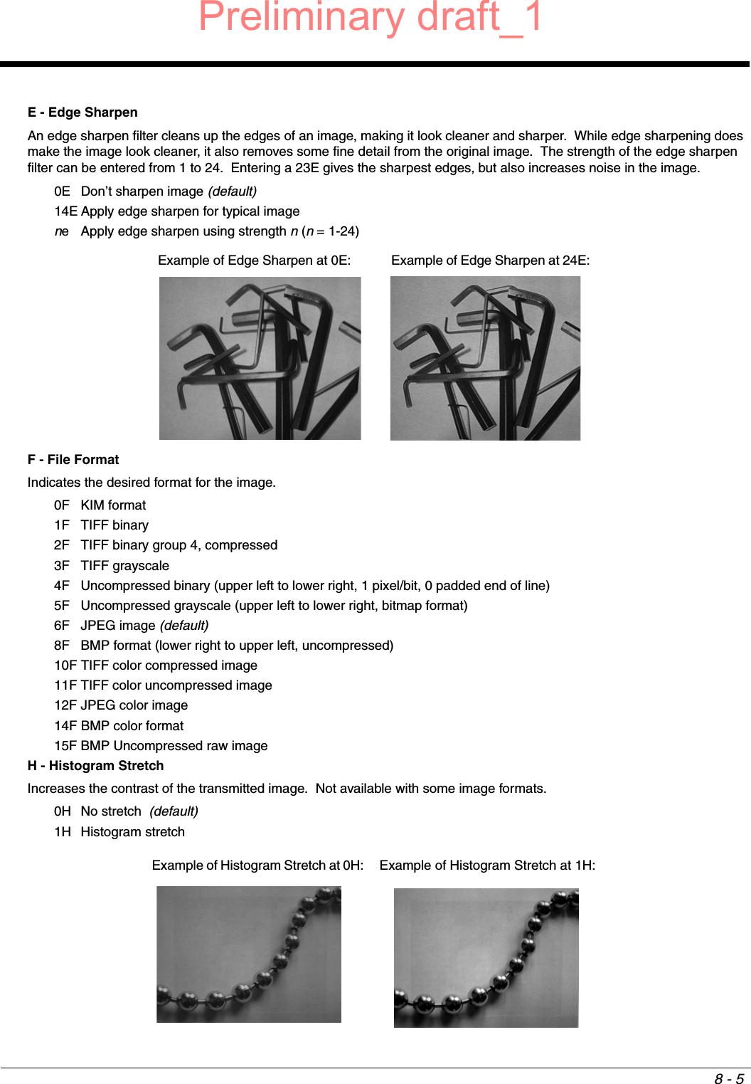
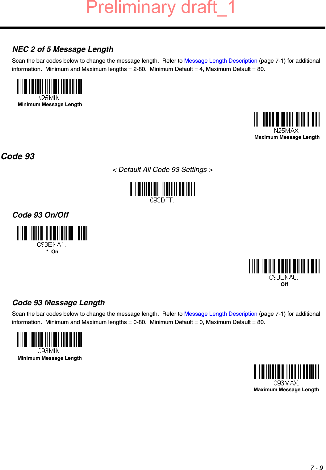
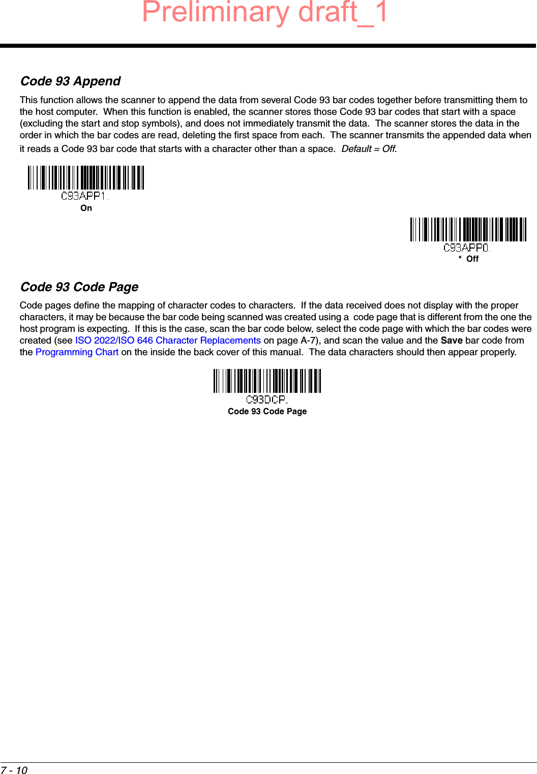
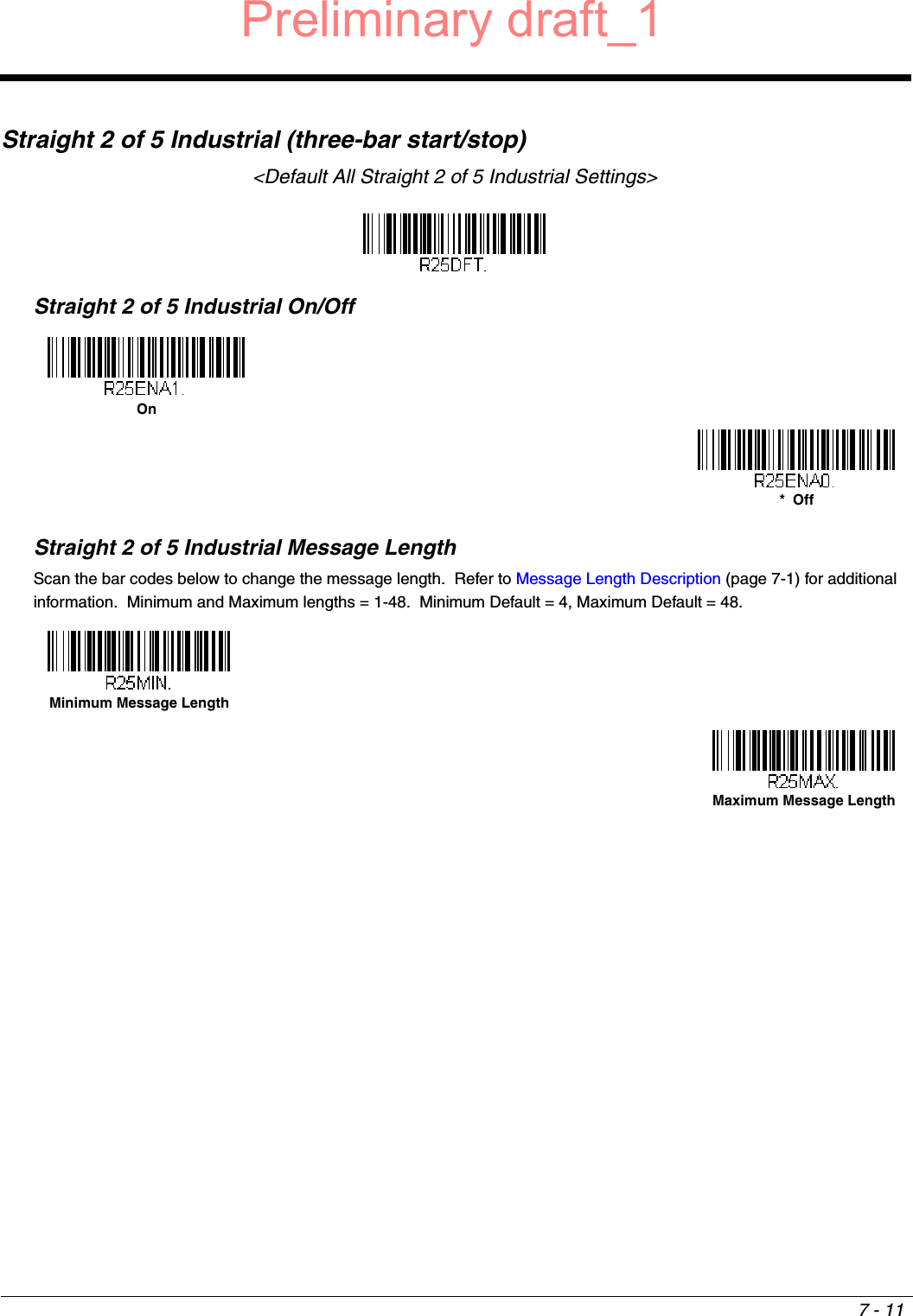
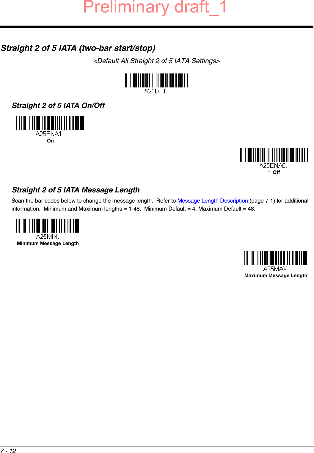
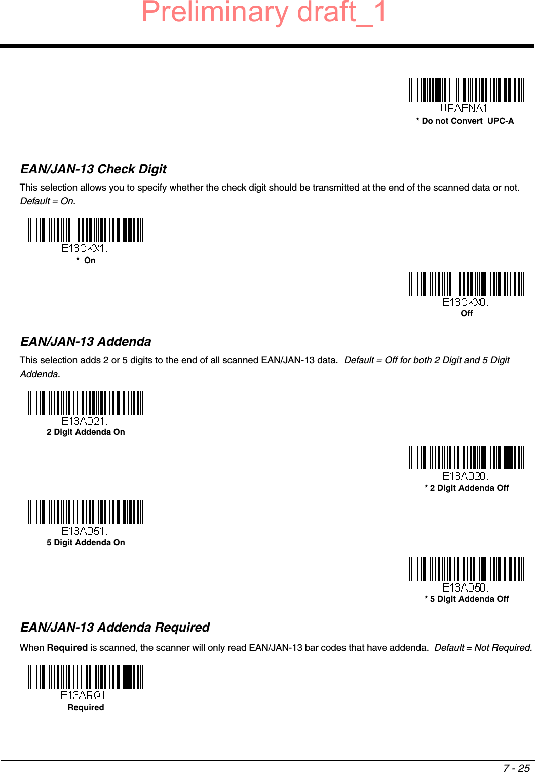
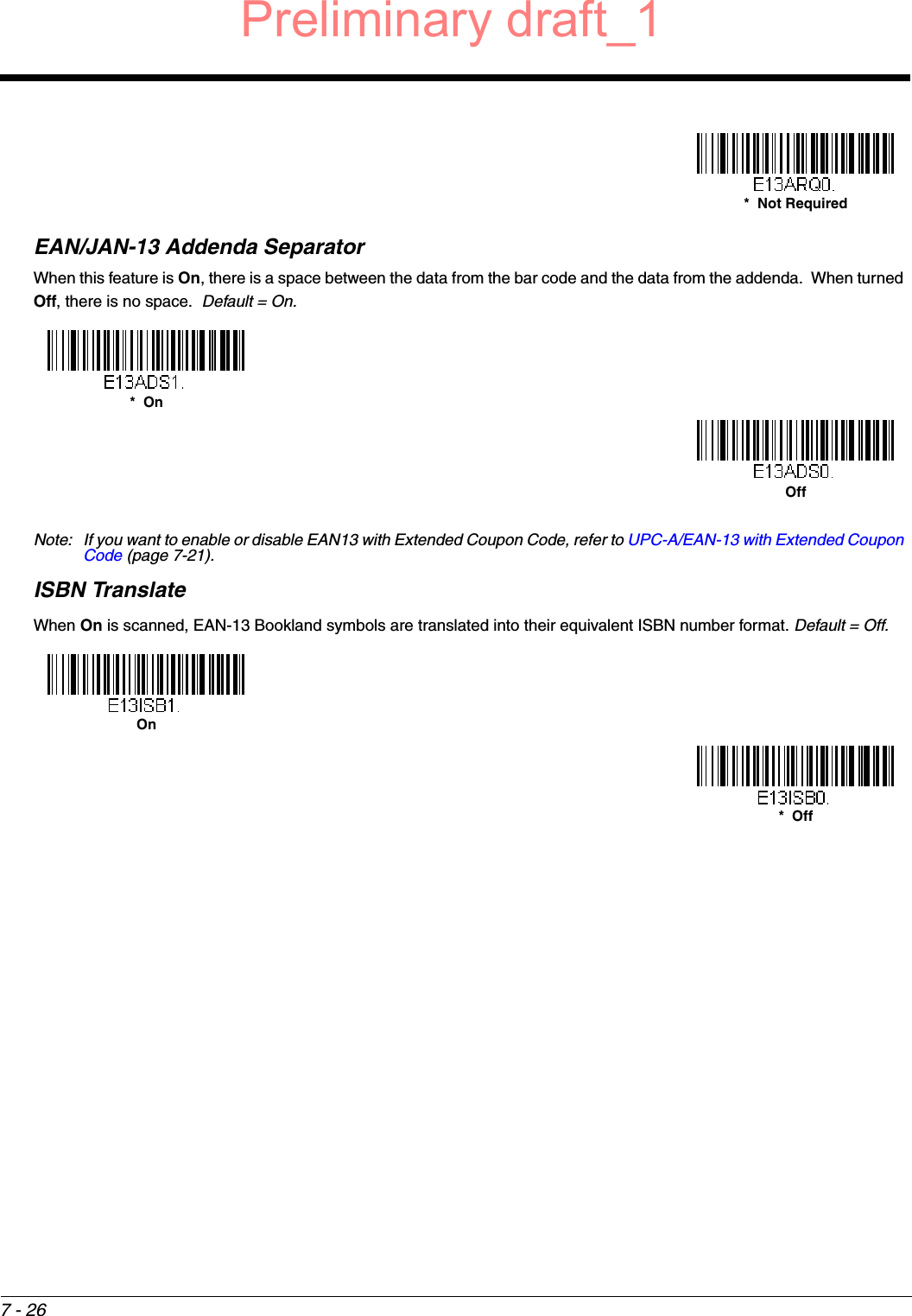
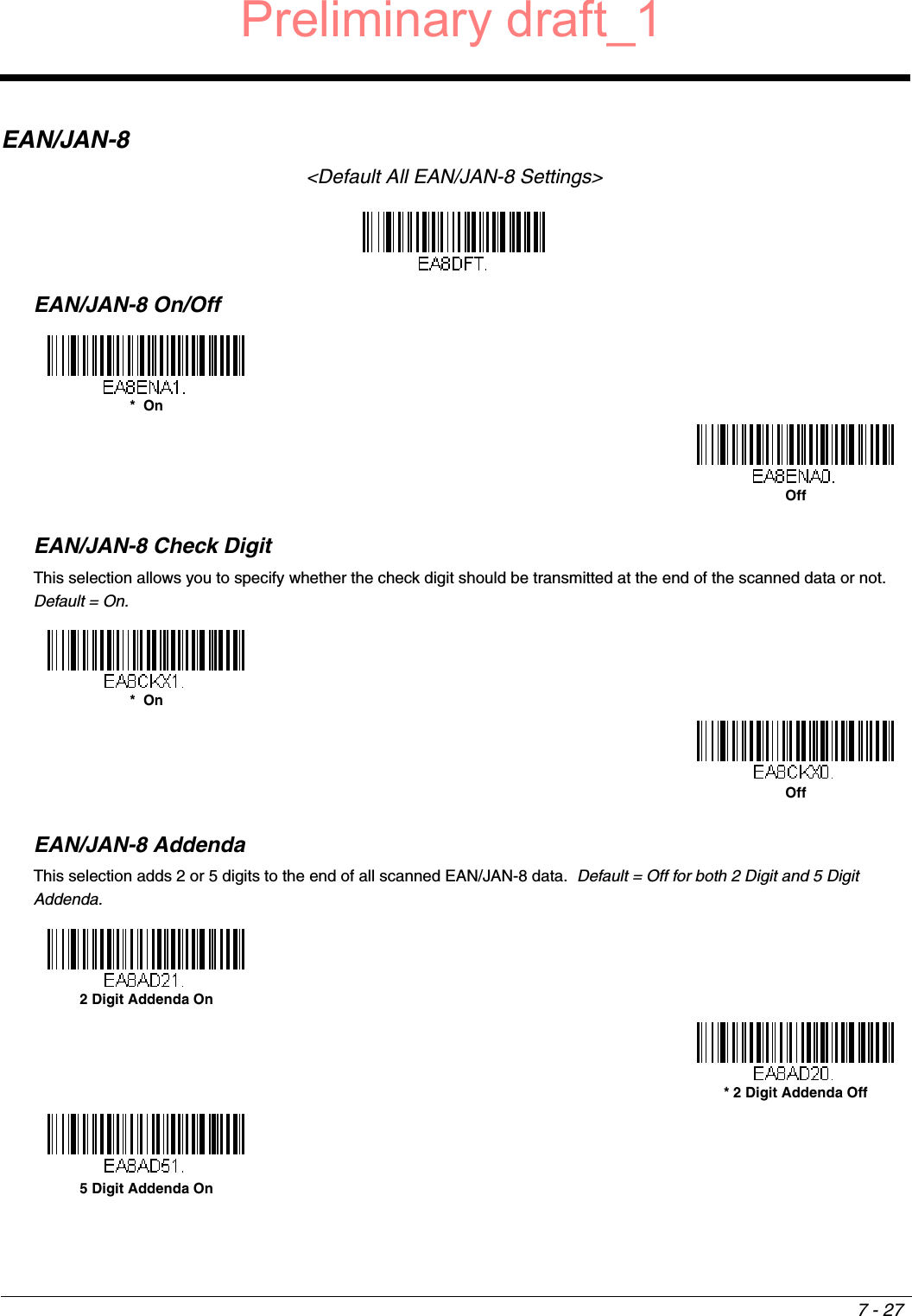
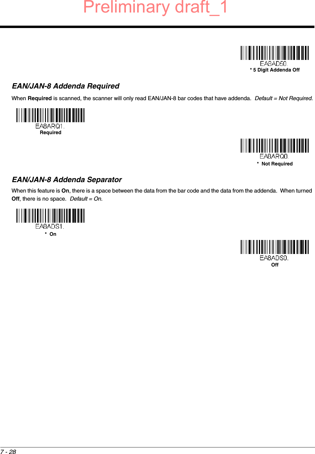
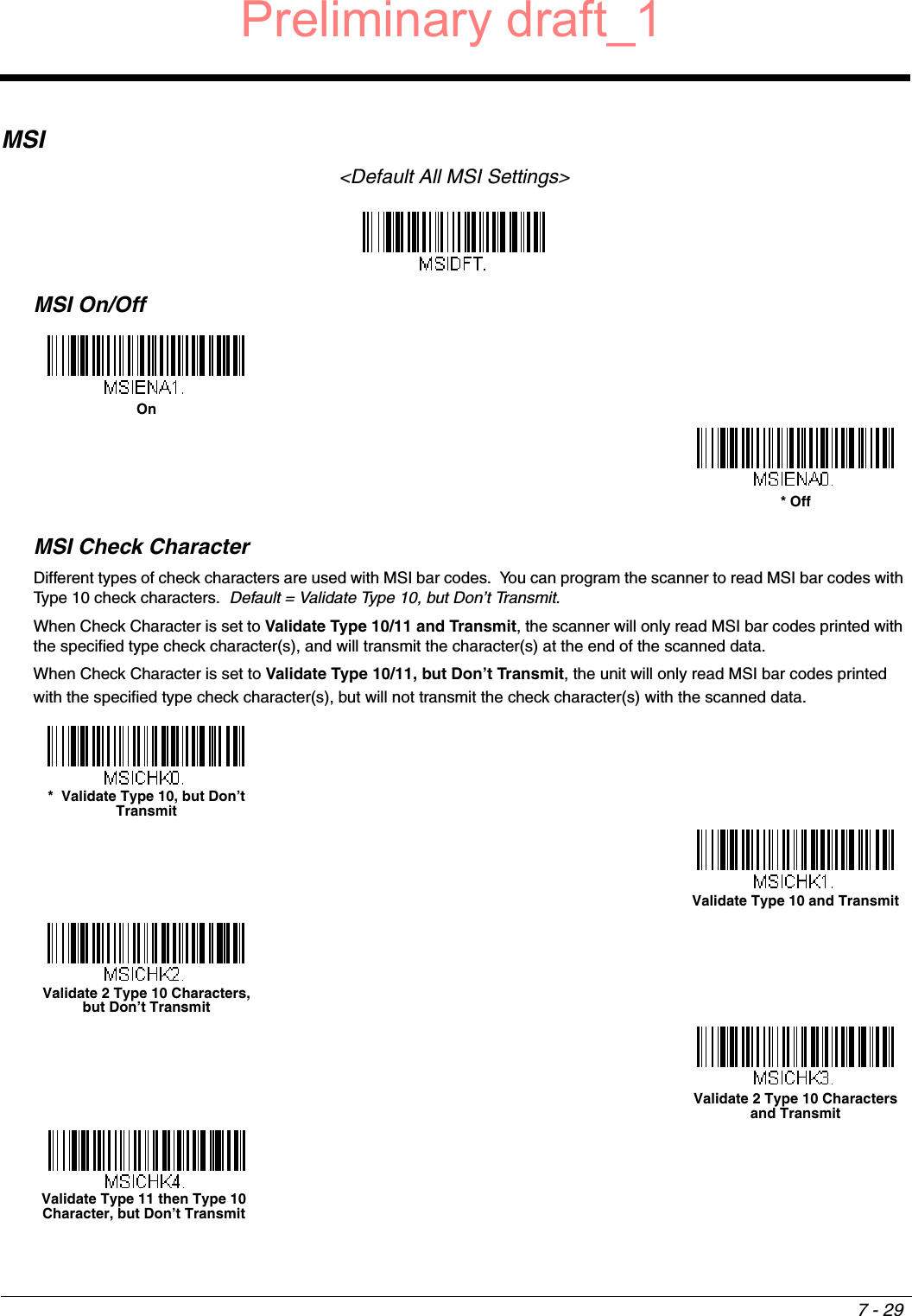
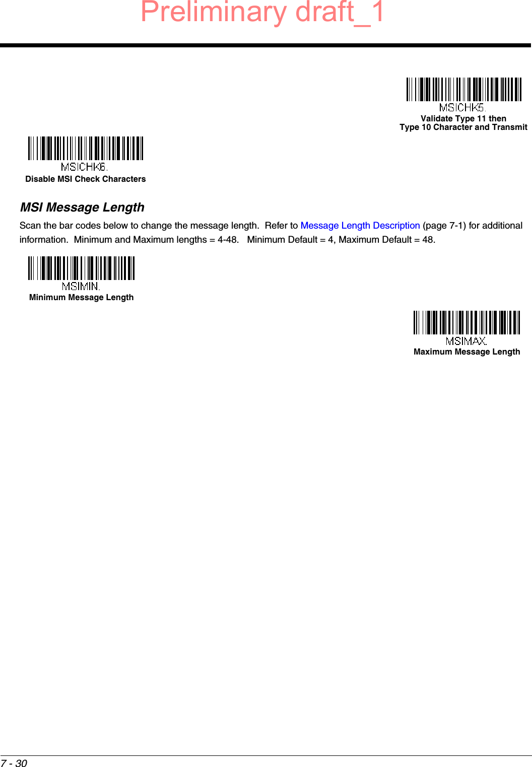
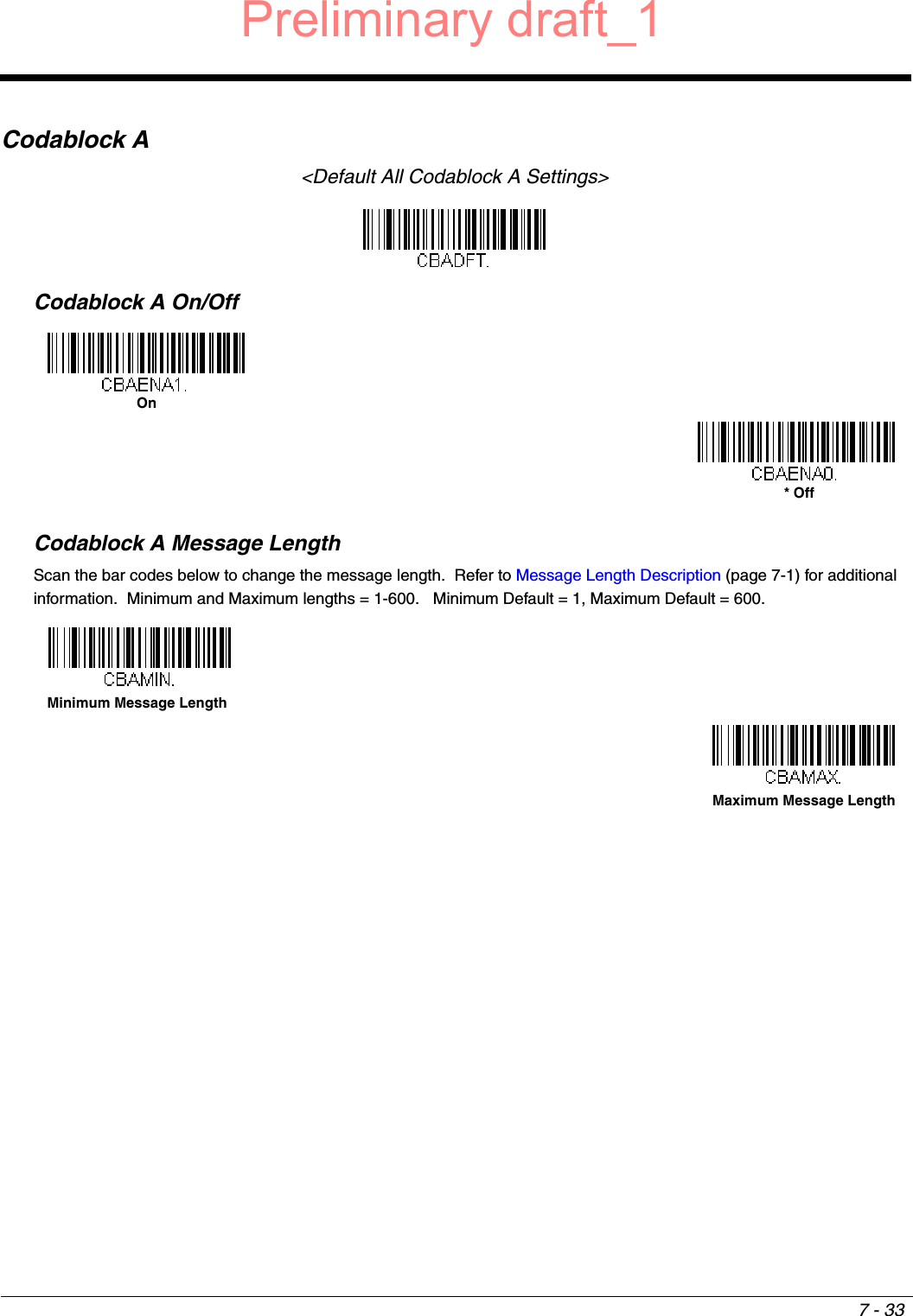
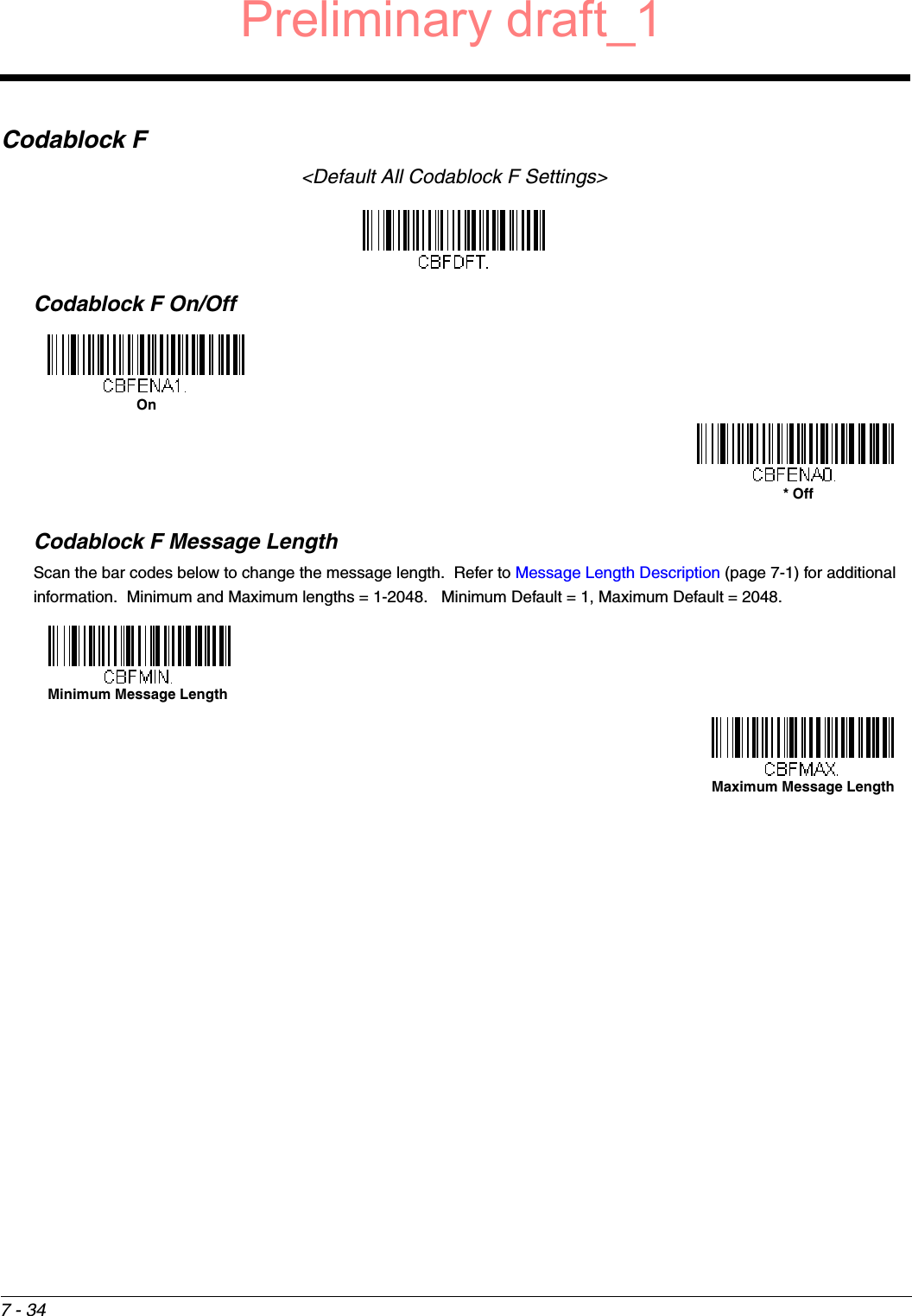
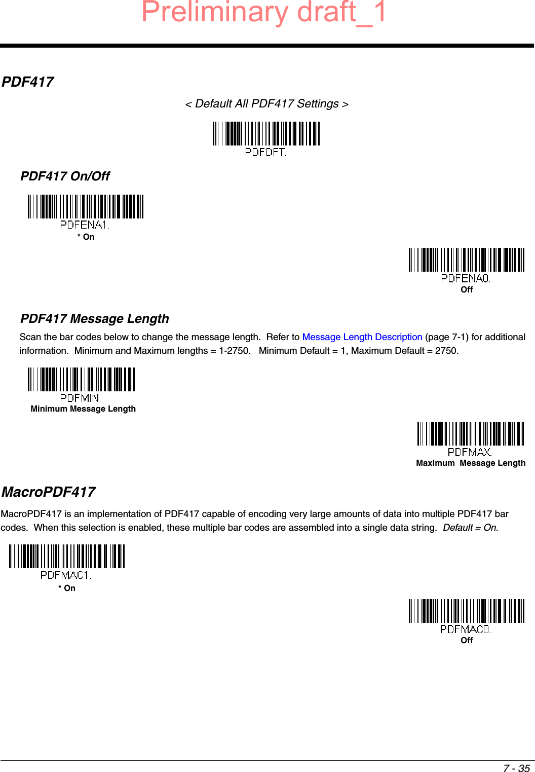
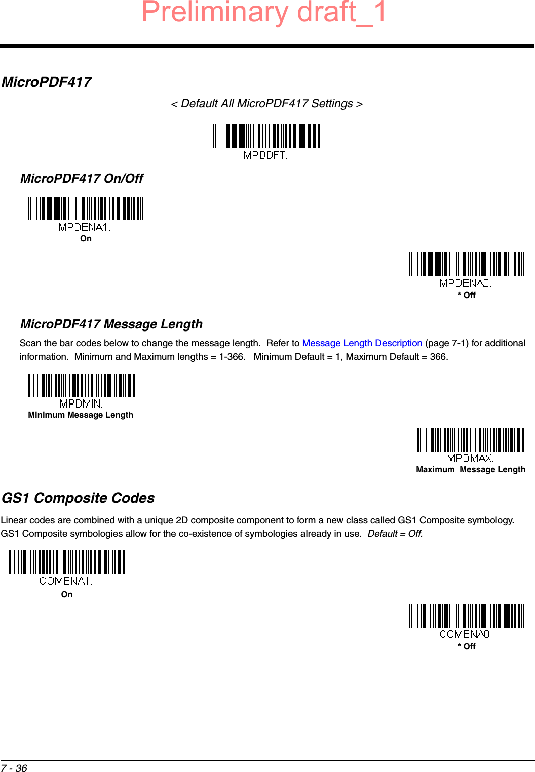
![7 - 6Full ASCIIIf Full ASCII Code 39 decoding is enabled, certain character pairs within the bar code symbol will be interpreted as a single character. For example: $V will be decoded as the ASCII character SYN, and /C will be decoded as the ASCII character #. Default = Off.Character pairs /M and /N decode as a minus sign and period respectively.Character pairs /P through /Y decode as 0 through 9.Code 39 Code PageCode pages define the mapping of character codes to characters. If the data received does not display with the proper characters, it may be because the bar code being scanned was created using a code page that is different from the one the host program is expecting. If this is the case, scan the bar code below, select the code page with which the bar codes were created (see ISO 2022/ISO 646 Character Replacements on page A-7), and scan the value and the Save bar code from the Programming Chart on the inside the back cover of this manual. The data characters should then appear properly.NUL %U DLE $PSP SPACE00@%VPP‘%Wp+PSOH $A DC1 $Q !/A 11AAQQa+Aq+QSTX $B DC2 $R “/B 22BBRRb+Br+RETX $C DC3 $S #/C 33CCSSc+Cs+SEOT $D DC4 $T $/D 44DDTTd+Dt+TENQ $E NAK $U %/E 55EEUUe+Eu+UACK $F SYN $V &/F 66FFVVf+Fv+VBEL $G ETB $W ‘/G77GGWWg+Gw+WBS $H CAN $X (/H 88HHXXh+Hx+XHT $I EM $Y )/I 99IIYYi+Iy+YLF $J SUB $Z */J :/ZJJZZj+Jz+ZVT $K ESC %A +/K ;%FKK[%Kk+K{%PFF $L FS %B ,/L <%GLL\%Ll+L|%QCR $M GS %C -- =%HMM]%Mm+M}%RSO $N RS %D .. >%INN^%Nn+N~%SSI $O US %E //O ?%JOO_%Oo+ODEL %TFull ASCII On* Full ASCII OffCode 39 Code PagePreliminary draft_1](https://usermanual.wiki/Honeywell/1981A.14C0587R-1981i-User-Manual-2-2015-02-10/User-Guide-2529878-Page-22.png)
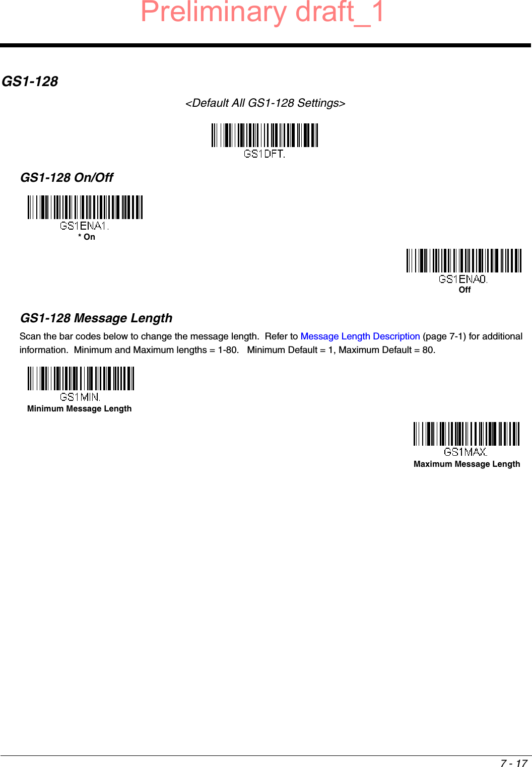
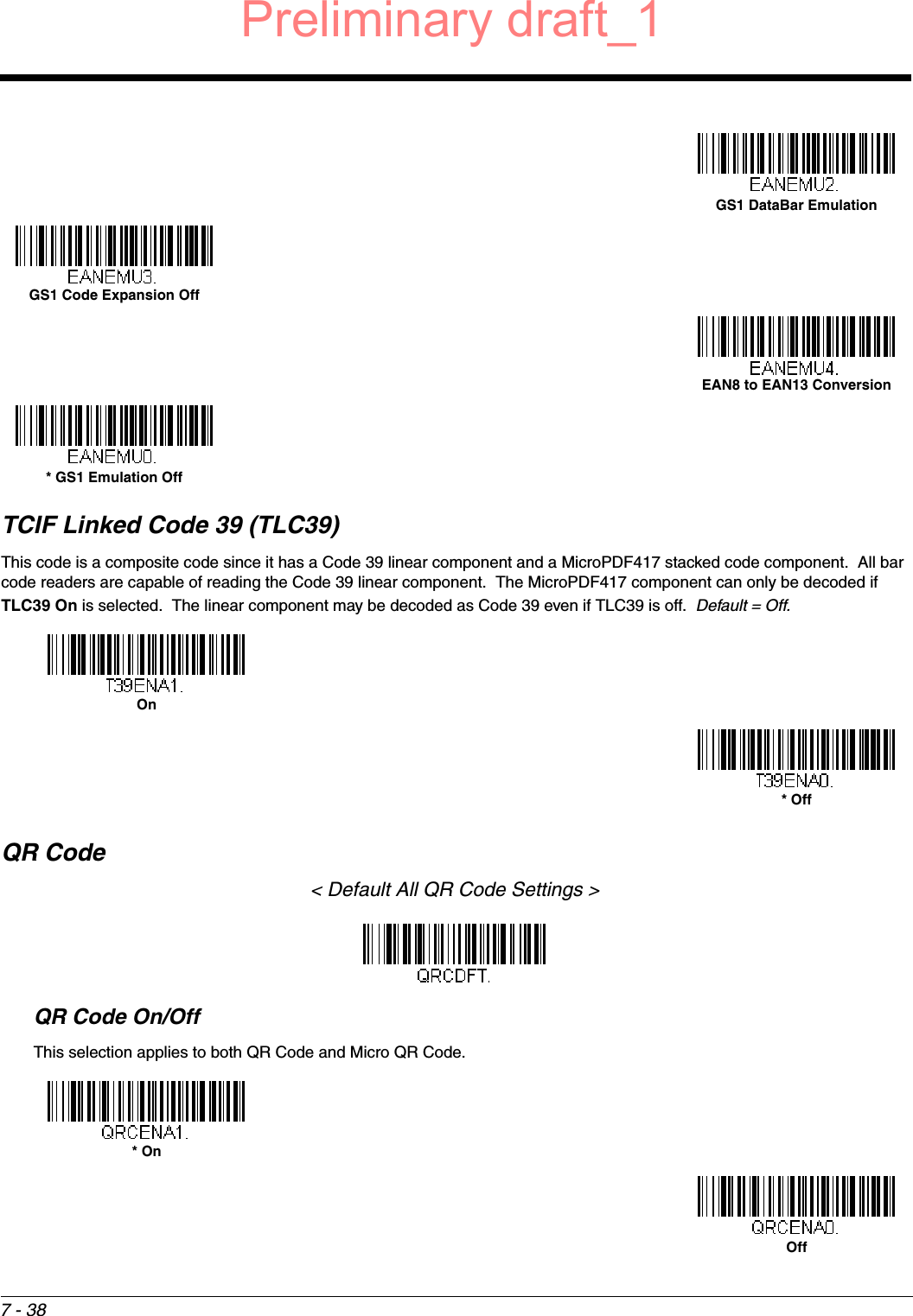
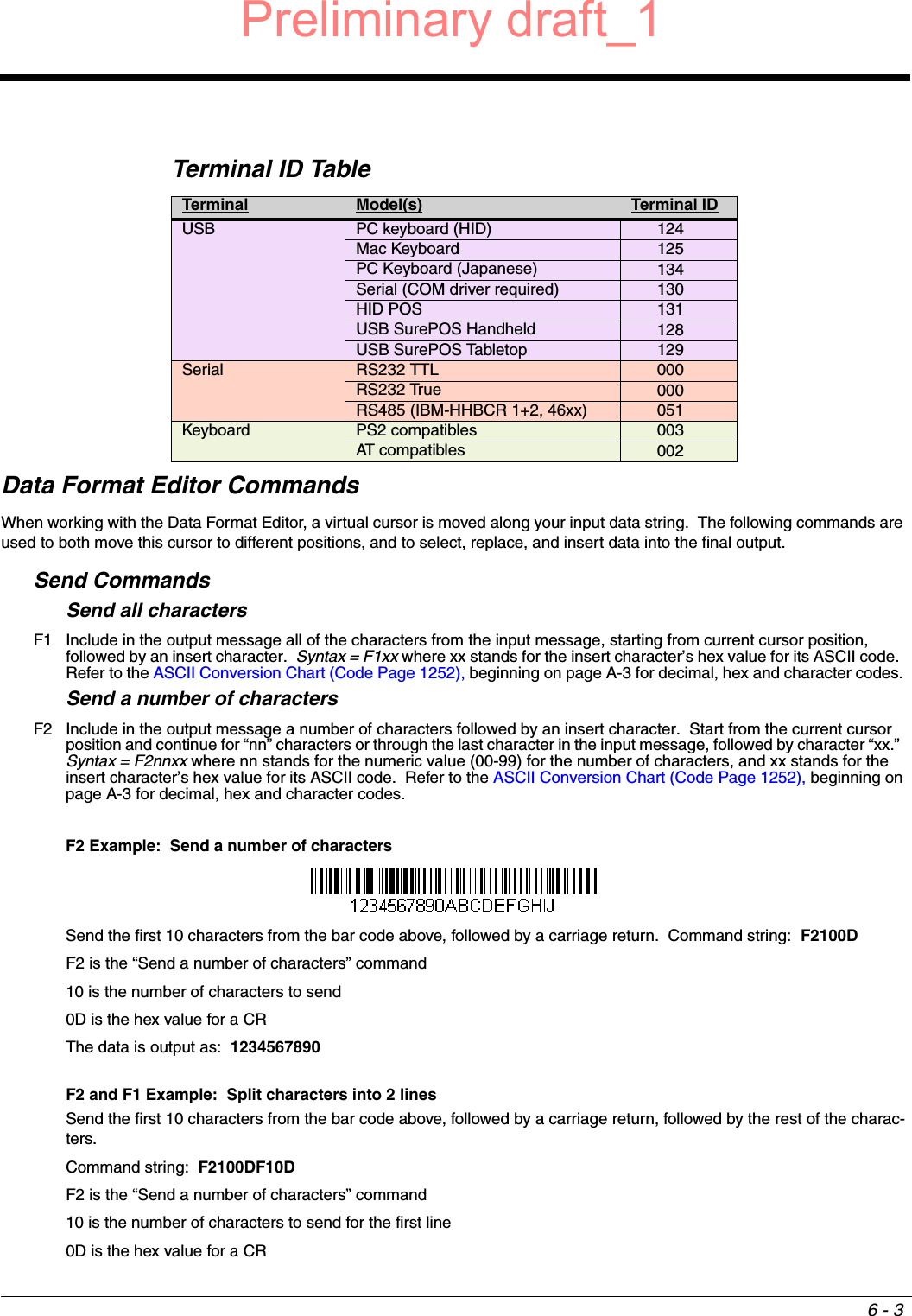
![7 - 37UPC/EAN VersionScan the UPC/EAN Version On bar code to decode GS1 Composite symbols that have a U.P.C. or an EAN linear compo-nent. (This does not affect GS1 Composite symbols with a GS1-128 or GS1 linear component.) Default = UPC/EAN Ver-sion Off.Note: If you scan coupons that have both UPC and GS1 DataBar codes, you may wish to scan and output only the data from the GS1 DataBar code. See Coupon GS1 DataBar Output (page 7-21) for further information.GS1 Composite Code Message LengthScan the bar codes below to change the message length. Refer to Message Length Description (page 7-1) for additional information. Minimum and Maximum lengths = 1-2435. Minimum Default = 1, Maximum Default = 2435.GS1 EmulationThe scanner can automatically format the output from any GS1 data carrier to emulate what would be encoded in an equivalent GS1-128 or GS1 DataBar symbol. GS1 data carriers include UPC-A and UPC-E, EAN-13 and EAN-8, ITF-14, GS1-128, and GS1-128 DataBar and GS1 Composites. (Any application that accepts GS1 data can be simplified since it only needs to recog-nize one data carrier type.)If GS1-128 Emulation is scanned, all retail codes (U.P.C., UPC-E, EAN8, EAN13) are expanded out to 16 digits. If the AIM ID is enabled, the value will be the GS1-128 AIM ID, ]C1 (see Symbology Charts on page A-1).If GS1 DataBar Emulation is scanned, all retail codes (U.P.C., UPC-E, EAN8, EAN13) are expanded out to 16 digits. If the AIM ID is enabled, the value will be the GS1-DataBar AIM ID, ]em (see Symbology Charts on page A-1).If GS1 Code Expansion Off is scanned, retail code expansion is disabled, and UPC-E expansion is controlled by the UPC-E0 Expand (page 7-22) setting. If the AIM ID is enabled, the value will be the GS1-128 AIM ID, ]C1 (see Symbology Charts on page A-1).If EAN8 to EAN13 Conversion is scanned, all EAN8 bar codes are converted to EAN13 format. Default = GS1 Emulation Off.UPC/EAN Version On* UPC/EAN Version OffMinimum Message LengthMaximum Message LengthGS1-128 EmulationPreliminary draft_1](https://usermanual.wiki/Honeywell/1981A.14C0587R-1981i-User-Manual-2-2015-02-10/User-Guide-2529878-Page-53.png)