Honeywell 1981A Barcode Scanner User Manual 14C0587R 1981i 2 2015 02 10
Honeywell International Inc Barcode Scanner 14C0587R 1981i 2 2015 02 10
Contents
- 1. 14C0587R-1981i-User Manual-1-2015-02-10
- 2. 14C0587R-1981i-User Manual-2-2015-02-10
- 3. 14C0587R-1981i-User Manual-3-2015-02-10
14C0587R-1981i-User Manual-2-2015-02-10
5 - 3
Function Code Transmit
When this selection is enabled and function codes are contained within the scanned data, the scanner transmits the function
code to the terminal. Charts of these function codes are provided in Supported Interface Keys starting on page 9-3. When the
scanner is in keyboard wedge mode, the scan code is converted to a key code before it is transmitted. Default = Enable.
Intercharacter, Interfunction, and Intermessage Delays
Some terminals drop information (characters) if data comes through too quickly. Intercharacter, interfunction, and intermessage
delays slow the transmission of data, increasing data integrity.
Intercharacter Delay
An intercharacter delay of up to 5000 milliseconds (in 5ms increments) may be placed between the transmission of each
character of scanned data. Scan the Intercharacter Delay bar code below, then scan the number of 5ms delays, and the
Save bar code using the Programming Chart inside the back cover of this manual.
To remove this delay, scan the Intercharacter Delay bar code, then set the number of delays to 0. Scan the Save bar code
using the Programming Chart inside the back cover of this manual.
Note: Intercharacter delays are not supported in USB serial emulation.
User Specified Intercharacter Delay
An intercharacter delay of up to 5000 milliseconds (in 5ms increments) may be placed after the transmission of a particular
character of scanned data. Scan the Delay Length bar code below, then scan the number of 5ms delays, and the Save
bar code using the Programming Chart inside the back cover of this manual.
Clear One Suffix
Clear All Suffixes
* Enable
Disable
12345
Intercharacter Delay
Prefix Scanned Data Suffix
Intercharacter Delay
Preliminary draft_1
5 - 4
Next, scan the Character to Trigger Delay bar code, then the 2-digit hex value for the ASCII character that will trigger the
delay ASCII Conversion Chart (Code Page 1252), beginning on page A-3.
To remove this delay, scan the Delay Length bar code, and set the number of delays to 0. Scan the Save bar code using
the Programming Chart inside the back cover of this manual.
Interfunction Delay
An interfunction delay of up to 5000 milliseconds (in 5ms increments) may be placed between the transmission of each
control character in the message string. Scan the Interfunction Delay bar code below, then scan the number of 5ms
delays, and the Save bar code using the Programming Chart inside the back cover of this manual.
To remove this delay, scan the Interfunction Delay bar code, then set the number of delays to 0. Scan the Save bar code
using the Programming Chart inside the back cover of this manual.
Intermessage Delay
An intermessage delay of up to 5000 milliseconds (in 5ms increments) may be placed between each scan transmission.
Scan the Intermessage Delay bar code below, then scan the number of 5ms delays, and the Save bar code using the
Programming Chart inside the back cover of this manual.
To remove this delay, scan the Intermessage Delay bar code, then set the number of delays to 0. Scan the Save bar code
using the Programming Chart inside the back cover of this manual.
Delay Length
Character to Trigger Delay
Interfunction Delays
Prefix Scanned Data Suffix
12345STX HT CR LF
Interfunction Delay
2nd Scan Transmission1st Scan Transmission
Intermessage Delay
Intermessage Delay
Preliminary draft_1

6 - 1
6
Data Formatting
Data Format Editor Introduction
You may use the Data Format Editor to change the scanner’s output. For example, you can use the Data Format Editor to insert
characters at certain points in bar code data as it is scanned. The selections in the following pages are used only if you wish to
alter the output. Default Data Format setting = None.
Normally, when you scan a bar code, it is output automatically. However, when you create a format, you must use a “send” com-
mand (see Send Commands on page 6-3) within the format program to output data.
Multiple formats may be programmed into the scanner. They are stacked in the order in which they are entered. However, the
following list presents the order in which formats are applied:
1. Specific Terminal ID, Actual Code ID, Actual Length
2. Specific Terminal ID, Actual Code ID, Universal Length
3. Specific Terminal ID, Universal Code ID, Actual Length
4. Specific Terminal ID, Universal Code ID, Universal Length
5. Universal Terminal ID, Actual Code ID, Actual Length
6. Universal Terminal ID, Actual Code ID, Universal Length
7. Universal Terminal ID, Universal Code ID, Actual Length
8. Universal Terminal ID, Universal Code ID, Universal Length
The maximum size of a data format configuration is 2000 bytes, which includes header information.
If a bar code is read that fails the first data format, the next data format, if there is one, will be used on the bar code data. If there
is no other data format, the raw data is output.
If you have changed data format settings, and wish to clear all formats and return to the factory defaults, scan the Default Data
Format code below.
Add a Data Format
Step 1. Scan the Enter Data Format symbol (page 6-2).
Step 2. Select Primary/Alternate Format
Determine if this will be your primary data format, or one of 3 alternate formats. This allows you to save a total of 4
different data formats. To program your primary format, scan 0 using the Programming Chart inside the back cover of
this manual. If you are programming an alternate format, scan 1, 2, or 3, depending on which alternate format you are
programming. (See "Primary/Alternate Data Formats" on page 6-13 for further information.)
Step 3. Terminal Type
Refer to Terminal ID Table (page 6-3) and locate the Terminal ID number for your PC. Scan three numeric bar codes
on the inside back cover to program the scanner for your terminal ID (you must enter 3 digits). For example, scan 0 0
3 for an AT wedge.
Note: 099 indicates all terminal types.
Step 4. Code I.D.
In the Symbology Charts, beginning on page A-1, find the symbology to which you want to apply the data format. Locate
the Hex value for that symbology and scan the 2 digit hex value from the Programming Chart inside the back cover of
this manual.
If you wish to create a data format for all symbologies, with the exception of some specific symbologies, refer to B8
(page 6-11).
If you are creating a data format for Batch Mode Quantity, use 35 for the Code I.D.
Note: 99 indicates all symbologies.
* Default Data Format
Preliminary draft_1
6 - 2
Step 5. Length
Specify what length (up to 9999 characters) of data will be acceptable for this symbology. Scan the four digit data length
from the Programming Chart inside the back cover of this manual. For example, 50 characters is entered as 0050.
Note: 9999 indicates all lengths.
Step 6. Editor Commands
Refer to Data Format Editor Commands (page 6-3). Scan the symbols that represent the command you want to enter.
Step 7. Scan Save to save your data format, or Discard to exit without saving your changes.
Other Programming Selections
Clear One Data Format
This deletes one data format for one symbology. If you are clearing the primary format, scan 0 from the Programming
Chart inside the back cover of this manual. If you are clearing an alternate format, scan 1, 2, or 3, depending on the
format you are clearing. Scan the Terminal Type and Code I.D. (see Symbology Charts on page A-1), and the bar code
data length for the specific data format that you want to delete. All other formats remain unaffected.
Clear all Data Formats
This clears all data formats.
Save to exit and save your data format changes.
Discard to exit without saving any data format changes.
Enter Data Format
Save
Discard
Clear One Data Format
Clear All Data Formats
Save
Discard
Preliminary draft_1
6 - 3
Data Format Editor Commands
When working with the Data Format Editor, a virtual cursor is moved along your input data string. The following commands are
used to both move this cursor to different positions, and to select, replace, and insert data into the final output.
Send Commands
Send all characters
F1 Include in the output message all of the characters from the input message, starting from current cursor position,
followed by an insert character. Syntax = F1xx where xx stands for the insert character’s hex value for its ASCII code.
Refer to the ASCII Conversion Chart (Code Page 1252), beginning on page A-3 for decimal, hex and character codes.
Send a number of characters
F2 Include in the output message a number of characters followed by an insert character. Start from the current cursor
position and continue for “nn” characters or through the last character in the input message, followed by character “xx.”
Syntax = F2nnxx where nn stands for the numeric value (00-99) for the number of characters, and xx stands for the
insert character’s hex value for its ASCII code. Refer to the ASCII Conversion Chart (Code Page 1252), beginning on
page A-3 for decimal, hex and character codes.
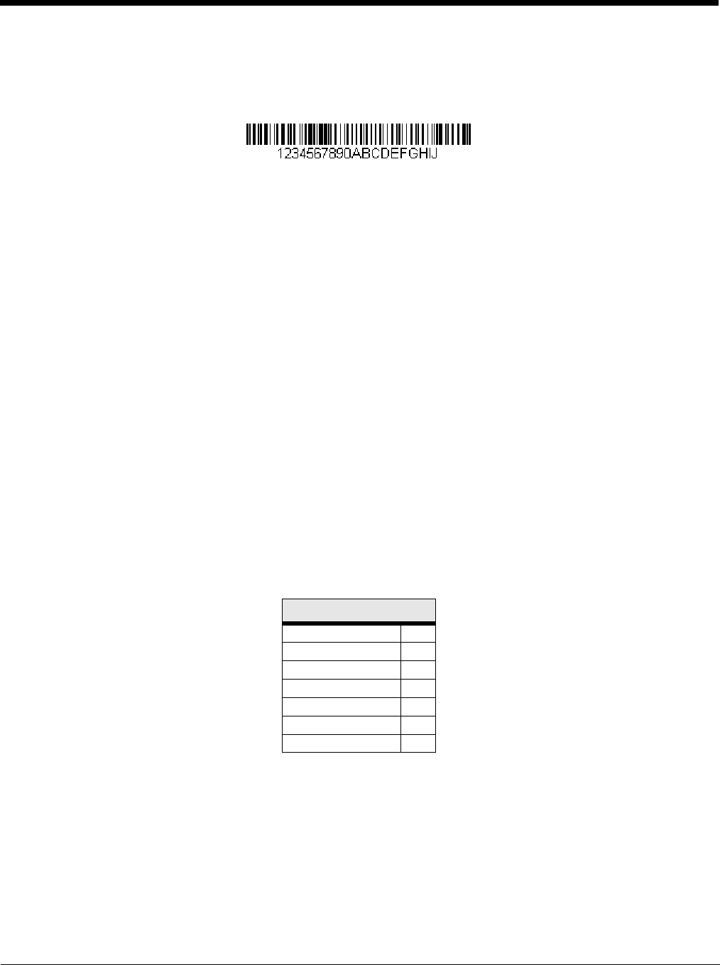
F2 Example: Send a number of characters
Send the first 10 characters from the bar code above, followed by a carriage return. Command string: F2100D
F2 is the “Send a number of characters” command
10 is the number of characters to send
0D is the hex value for a CR
The data is output as: 1234567890
F2 and F1 Example: Split characters into 2 lines
Send the first 10 characters from the bar code above, followed by a carriage return, followed by the rest of the charac-
ters.
Command string: F2100DF10D
F2 is the “Send a number of characters” command
10 is the number of characters to send for the first line
0D is the hex value for a CR
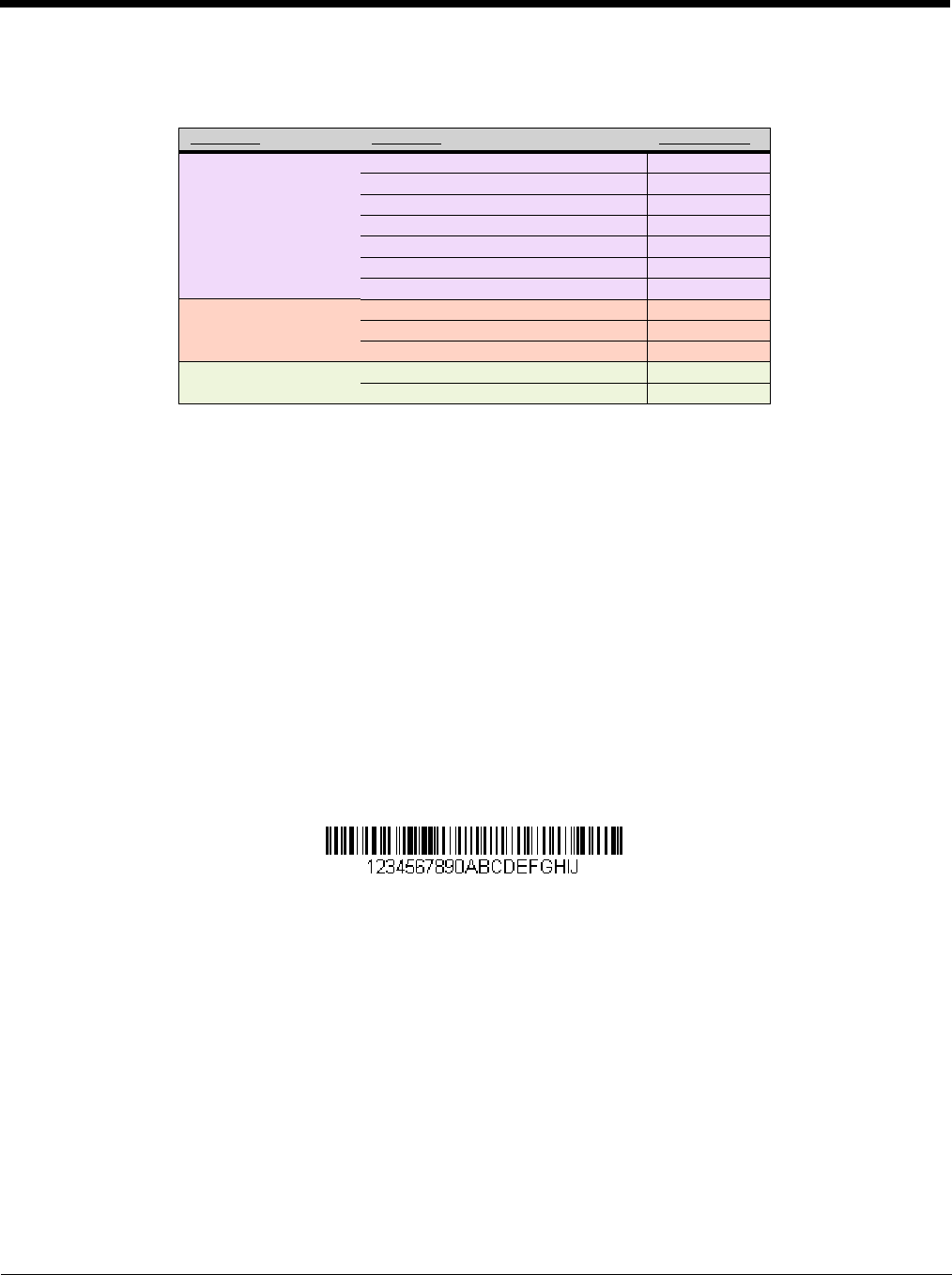
Terminal ID Table
Terminal Model(s) Terminal ID
USB PC keyboard (HID) 124
Mac Keyboard 125
PC Keyboard (Japanese) 134
Serial (COM driver required) 130
HID POS 131
USB SurePOS Handheld 128
USB SurePOS Tabletop 129
Serial RS232 TTL 000
RS232 True 000
RS485 (IBM-HHBCR 1+2, 46xx) 051
Keyboard PS2 compatibles 003
AT compatibles 002
Preliminary draft_1

6 - 4
F1 is the “Send all characters” command
0D is the hex value for a CR
The data is output as:
1234567890
ABCDEFGHIJ
<CR>
Send all characters up to a particular character
F3 Include in the output message all characters from the input message, starting with the character at the current cursor
position and continuing to, but not including, the search character “ss,” followed by an insert character. The cursor is
moved forward to the “ss” character. Syntax = F3ssxx where ss stands for the search character’s hex value for its ASCII
code, and xx stands for the insert character’s hex value for its ASCII code.
Refer to the ASCII Conversion Chart (Code Page 1252), beginning on page A-3 for decimal, hex and character codes.
F3 Example: Send all characters up to a particular character
Using the bar code above, send all characters up to but not including “D,” followed by a carriage return.
Command string: F3440D
F3 is the “Send all characters up to a particular character” command
44 is the hex value for a 'D”
0D is the hex value for a CR
The data is output as:
1234567890ABC
<CR>
Send all characters up to a string
B9 Include in the output message all characters from the input message, starting with the character at the current cursor
position and continuing to, but not including, the search string “s...s.” The cursor is moved forward to the beginning of
the “s...s” string. Syntax = B9nnnns...s where nnnn stands for the length of the string, and s...s stands for the string to
be matched. The string is made up of hex values for the characters in the string. Refer to the ASCII Conversion Chart
(Code Page 1252), beginning on page A-3 for decimal, hex and character codes.
B9 Example: Send all characters up to a defined string
Using the bar code above, send all characters up to but not including “AB.”
Command string: B900024142
B9 is the “Send all characters up to a string” command
0002 is the length of the string (2 characters)
41 is the hex value for A
42 is the hex value for B
The data is output as: 1234567890
Send all but the last characters
E9 Include in the output message all but the last “nn” characters, starting from the current cursor position. The cursor is
moved forward to one position past the last input message character included. Syntax = E9nn where nn stands for the
numeric value (00-99) for the number of characters that will not be sent at the end of the message.
Preliminary draft_1

6 - 5
Insert a character multiple times
F4 Send “xx” character “nn” times in the output message, leaving the cursor in the current position. Syntax = F4xxnn where
xx stands for the insert character’s hex value for its ASCII code, and nn is the numeric value (00-99) for the number of
times it should be sent. Refer to the ASCII Conversion Chart (Code Page 1252), beginning on page A-3 for decimal,
hex and character codes.
E9 and F4 Example: Send all but the last characters, followed by 2 tabs
Send all characters except for the last 8 from the bar code above, followed by 2 tabs.
Command string: E908F40902
E9 is the “Send all but the last characters” command
08 is the number of characters at the end to ignore
F4 is the “Insert a character multiple times” command
09 is the hex value for a horizontal tab
02 is the number of times the tab character is sent
The data is output as: 1234567890AB <tab><tab>
Insert a string
BA Send “ss” string of “nn” length in the output message, leaving the cursor in the current position. Syntax = BAnnnns...s
where nnnn stands for the length of the string, and s...s stands for the string. The string is made up of hex values for
the characters in the string. Refer to the ASCII Conversion Chart (Code Page 1252), beginning on page A-3 for decimal,
hex and character codes.
B9 and BA Example: Look for the string “AB” and insert 2 asterisks (**)
Using the bar code above, send all characters up to but not including “AB.” Insert 2 asterisks at that point, and send
the rest of the data with a carriage return after.
Command string: B900024142BA00022A2AF10D
B9 is the “Send all characters up to a string” command
0002 is the length of the string (2 characters)
41 is the hex value for A
42 is the hex value for B
BA is the “Insert a string” command
0002 is the length of the string to be added (2 characters)
2A is the hex value for an asterisk (*)
2A is the hex value for an asterisk (*)
F1 is the “Send all characters” command
0D is the hex value for a CR
The data is output as:
1234567890**ABCDEFGHIJ
<CR>
Insert symbology name
B3 Insert the name of the bar code’s symbology in the output message, without moving the cursor. Only symbologies with
a Honeywell ID are included (see Symbology Charts on page A-1). Refer to the ASCII Conversion Chart (Code Page
1252), beginning on page A-3 for decimal, hex and character codes.
Preliminary draft_1
6 - 6
Insert bar code length
B4 Insert the bar code’s length in the output message, without moving the cursor. The length is expressed as a numeric
string and does not include leading zeroes.
B3 and B4 Example: Insert the symbology name and length
Send the symbology name and length before the bar code data from the bar code above. Break up these insertions
with spaces. End with a carriage return.
Command string: B3F42001B4F42001F10D
B3 is the “Insert symbology name” command
F4 is the “Insert a character multiple times” command
20 is the hex value for a space
01 is the number of times the space character is sent
B4 is the “Insert bar code length” command
F4 is the “Insert a character multiple times” command
20 is the hex value for a space
01 is the number of times the space character is sent
F1 is the “Send all characters” command
0D is the hex value for a CR
The data is output as:
Code128 20 1234567890ABCDEFGHIJ
<CR>
Insert key strokes
B5 Insert a key stroke or combination of key strokes. Key strokes are dependent on your keyboard (see Unicode Key Maps
on page A-10). Any key can be inserted, including arrows and functions. Syntax = B5xxssnn where xx is the number
of keys pressed (without key modifiers), ss is the key modifier from the table below, and nn is the key number from the
Unicode Key Maps, page A-10.
For example, B501021F inserts an “A” on a 104 key, U.S. style keyboard. B5 = the command, 01 = number of keys
pressed (without the key modifier), 02 is the key modifier for Shift Right, and 1F is the “a” key. If a lower case “a” were
to be inserted, B501001F would be entered.
If there are three keystrokes, the syntax would change from B5xxssnn for one keystroke to B5xxssnnssnnssnn. An
example that would insert "abc" is as follows: B503001F00320030F833.
Note: Key modifiers can be added together when needed. Example: Control Left+Shift Left = 11.
Move Commands
Move the cursor forward a number of characters
F5 Move the cursor ahead “nn” characters from current cursor position.
Syntax = F5nn where nn is the numeric value (00-99) for the number of characters the cursor should be moved ahead.
Key Modifiers
No Key Modifier 00
Shift Left 01
Shift Right 02
Alt Left 04
Alt Right 08
Control Left 10
Control Right 20
Preliminary draft_1

6 - 7
F5 Example: Move the cursor forward and send the data
Move the cursor forward 3 characters, then send the rest of the bar code data from the bar code above. End with a
carriage return.
Command string: F503F10D
F5 is the “Move the cursor forward a number of characters” command
03 is the number of characters to move the cursor
F1 is the “Send all characters” command
0D is the hex value for a CR
The data is output as:
4567890ABCDEFGHIJ
<CR>
Move the cursor backward a number of characters
F6 Move the cursor back “nn” characters from current cursor position.
Syntax = F6nn where nn is the numeric value (00-99) for the number of characters the cursor should be moved back.
Move the cursor to the beginning
F7 Move the cursor to the first character in the input message. Syntax = F7.
FE and F7 Example: Manipulate bar codes that begin with a 1
Search for bar codes that begin with a 1. If a bar code matches, move the cursor back to the beginning of the data and
send 6 characters followed by a carriage return. Using the bar code above:
Command string: FE31F7F2060D
FE is the “Compare characters” command
31 is the hex value for 1
F7 is the “Move the cursor to the beginning” command
F2 is the “Send a number of characters” command
06 is the number of characters to send
0D is the hex value for a CR
The data is output as:
123456
<CR>
Move the cursor to the end
EA Move the cursor to the last character in the input message. Syntax = EA.
Search Commands
Search forward for a character
F8 Search the input message forward for “xx” character from the current cursor position, leaving the cursor pointing to the
“xx” character. Syntax = F8xx where xx stands for the search character’s hex value for its ASCII code.
Refer to the ASCII Conversion Chart (Code Page 1252), beginning on page A-3 for decimal, hex and character codes.
Preliminary draft_1

6 - 8
F8 Example: Send bar code data that starts after a particular character
Search for the letter “D” in bar codes and send all the data that follows, including the “D.” Using the bar code above:
Command string: F844F10D
F8 is the “Search forward for a character” command
44 is the hex value for “D”
F1 is the “Send all characters” command
0D is the hex value for a CR
The data is output as:
DEFGHIJ
<CR>
Search backward for a character
F9 Search the input message backward for “xx” character from the current cursor position, leaving the cursor pointing to
the “xx” character. Syntax = F9xx where xx stands for the search character’s hex value for its ASCII code.
Refer to the ASCII Conversion Chart (Code Page 1252), beginning on page A-3 for decimal, hex and character codes.
Search forward for a string
B0 Search forward for “s” string from the current cursor position, leaving cursor pointing to “s” string. Syntax = B0nnnnS
where nnnn is the string length (up to 9999), and S consists of the ASCII hex value of each character in the match string.
For example, B0000454657374 will search forward for the first occurrence of the 4 character string “Test.”
Refer to the ASCII Conversion Chart (Code Page 1252), beginning on page A-3 for decimal, hex and character codes.
B0 Example: Send bar code data that starts after a string of characters
Search for the letters “FGH” in bar codes and send all the data that follows, including “FGH.” Using the bar code
above:
Command string: B00003464748F10D
B0 is the “Search forward for a string” command
0003 is the string length (3 characters)
46 is the hex value for “F”
47 is the hex value for “G”
48 is the hex value for “H”
F1 is the “Send all characters” command
0D is the hex value for a CR
The data is output as:
FGHIJ
<CR>
Search backward for a string
B1 Search backward for “s” string from the current cursor position, leaving cursor pointing to “s” string. Syntax = B1nnnnS
where nnnn is the string length (up to 9999), and S consists of the ASCII hex value of each character in the match string.
For example, B1000454657374 will search backward for the first occurrence of the 4 character string “Test.”
Refer to the ASCII Conversion Chart (Code Page 1252), beginning on page A-3 for decimal, hex and character codes.
Preliminary draft_1

6 - 9
Search forward for a non-matching character
E6 Search the input message forward for the first non-“xx” character from the current cursor position, leaving the cursor
pointing to the non-“xx” character. Syntax = E6xx where xx stands for the search character’s hex value for its ASCII
code. Refer to the ASCII Conversion Chart (Code Page 1252), beginning on page A-3 for decimal, hex and character
codes.
E6 Example: Remove zeroes at the beginning of bar code data
This example shows a bar code that has been zero filled. You may want to ignore the zeroes and send all the data that
follows. E6 searches forward for the first character that is not zero, then sends all the data after, followed by a carriage
return. Using the bar code above:
Command string: E630F10D
E6 is the “Search forward for a non-matching character” command
30 is the hex value for 0
F1 is the “Send all characters” command
0D is the hex value for a CR
The data is output as:
37692
<CR>
Search backward for a non-matching character
E7 Search the input message backward for the first non-“xx” character from the current cursor position, leaving the cursor
pointing to the non-“xx” character. Syntax = E7xx where xx stands for the search character’s hex value for its ASCII
code. Refer to the ASCII Conversion Chart (Code Page 1252), beginning on page A-3 for decimal, hex and character
codes.
Miscellaneous Commands
Suppress characters
FB Suppress all occurrences of up to 15 different characters, starting at the current cursor position, as the cursor is
advanced by other commands. When the FC command is encountered, the suppress function is terminated. The
cursor is not moved by the FB command.
Syntax = FBnnxxyy . .zz where nn is a count of the number of suppressed characters in the list, and xxyy .. zz is the list
of characters to be suppressed.
FB Example: Remove spaces in bar code data
This example shows a bar code that has spaces in the data. You may want to remove the spaces before sending the
data. Using the bar code above:
Command string: FB0120F10D
FB is the “Suppress characters” command
01 is the number of character types to be suppressed
20 is the hex value for a space
F1 is the “Send all characters” command
0D is the hex value for a CR
The data is output as:
34567890
<CR>
Preliminary draft_1

6 - 10
Stop suppressing characters
FC Disables suppress filter and clear all suppressed characters. Syntax = FC.
Replace characters
E4 Replaces up to 15 characters in the output message, without moving the cursor. Replacement continues until the E5
command is encountered. Syntax = E4nnxx1xx2yy1yy2...zz1zz2 where nn is the total count of the number of characters
in the list (characters to be replaced plus replacement characters); xx1 defines characters to be replaced and xx2 defines
replacement characters, continuing through zz1 and zz2.
E4 Example: Replace zeroes with CRs in bar code data
If the bar code has characters that the host application does not want included, you can use the E4 command to
replace those characters with something else. In this example, you will replace the zeroes in the bar code above with
carriage returns.
Command string: E402300DF10D
E4 is the “Replace characters” command
02 is the total count of characters to be replaced, plus the replacement characters (0 is replaced by CR, so total char-
acters = 2)
30 is the hex value for 0
0D is the hex value for a CR (the character that will replace the 0)
F1 is the “Send all characters” command
0D is the hex value for a CR
The data is output as:
1234
5678
ABC
<CR>
Stop replacing characters
E5 Terminates character replacement. Syntax = E5.
Compare characters
FE Compare the character in the current cursor position to the character “xx.” If characters are equal, move the cursor
forward one position. Syntax = FExx where xx stands for the comparison character’s hex value for its ASCII code.
Refer to the ASCII Conversion Chart (Code Page 1252), beginning on page A-3 for decimal, hex and character codes.
Compare string
B2 Compare the string in the input message to the string “s.” If the strings are equal, move the cursor forward past the end
of the string. Syntax = B2nnnnS where nnnn is the string length (up to 9999), and S consists of the ASCII hex value
of each character in the match string. For example, B2000454657374 will compare the string at the current cursor
position with the 4 character string “Test.”
Refer to the ASCII Conversion Chart (Code Page 1252), beginning on page A-3 for decimal, hex and character codes.
Check for a number
EC Check to make sure there is an ASCII number at the current cursor position. The format is aborted if the character is
not numeric.
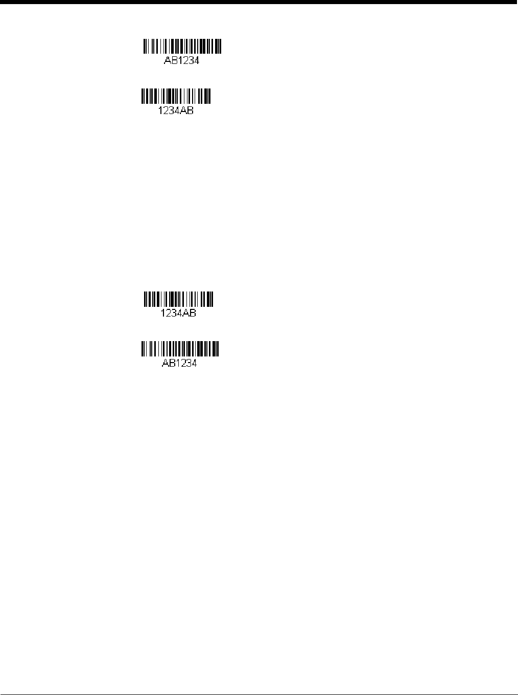
EC Example: Only output the data if the bar code begins with a number
If you want only data from bar codes that begin with a number, you can use EC to check for the number.
Command string: ECF10D
EC is the “Check for a number” command
F1 is the “Send all characters” command
0D is the hex value for a CR
Preliminary draft_1
6 - 11
If this bar code is read, the next data format, if there is one, will be used on the data. If there
is no other format, the format fails and the raw data is output as AB1234.
If this bar code is read: the data is output as:
1234AB
<CR>
Check for non-numeric character
ED Check to make sure there is a non-numeric ASCII character at the current cursor position. The format is aborted if the
character is numeric.
ED Example: Only output the data if the bar code begins with a letter
If you want only data from bar codes that begin with a letter, you can use ED to check for the letter.
Command string: EDF10D
ED is the “Check for a non-numeric character” command
F1 is the “Send all characters” command
0D is the hex value for a CR
If this bar code is read, the next data format, if there is one, will be used on this data. If there
is no other format, the format fails and the raw data is output as 1234AB.
If this bar code is read: the data is output as:
AB1234
<CR>
Insert a delay
EF Inserts a delay of up to 49,995 milliseconds (in multiples of 5), starting from the current cursor position. Syntax = EFnnnn
where nnnn stands for the delay in 5ms increments, up to 9999. This command can only be used with keyboard
emulation.a
Discard Data
B8 Discards types of data. For example, you may want to discard Code 128 bar codes that begin with the letter A. In step
4 (page 6-1), select 6A (for Code 128), and in step 5, select 9999 (for all lengths). Enter FE41B8 to compare and discard
Code 128 bar codes that begin with the letter A. Syntax = B8.
Note: The B8 command must be entered after all other commands.
The Data Format must be Required (see page 6-12) in order for the B8 command to work.
If Data Format is On, but Not Required (page 6-12), bar code data that meets the B8 format is scanned and output
as usual.
Because the data format needs to be On and Required (page 6-12) for the B8 command, you must input data formats
for all bar codes you wish to discard as well as all bar codes you wish to output.
Other data format settings impact the B8 command. If Data Format Non-Match Error Tone is On (page 6-13), the
scanner emits an error tone. If Data format Non-Match Error Tone is Off, the code is disabled for reading and no
tone is sounded.
Preliminary draft_1
6 - 12
Data Formatter
When Data Formatter is turned Off, the bar code data is output to the host as read, including prefixes and suffixes.
You may wish to require the data to conform to a data format you have created and saved. The following settings can be applied
to your data format:
Data Formatter On, Not Required, Keep Prefix/Suffix
Scanned data is modified according to your data format, and prefixes and suffixes are transmitted.
Data Formatter On, Not Required, Drop Prefix/Suffix
Scanned data is modified according to your data format. If a data format is found for a particular symbol, those prefixes and
suffixes are not transmitted. If a data format is not found for that symbol, the prefixes and suffixes are transmitted.
Data Format Required, Keep Prefix/Suffix
Scanned data is modified according to your data format, and prefixes and suffixes are transmitted. Any data that does not
match your data format requirements generates an error tone and the data in that bar code is not transmitted. If you wish
to process this type of bar code without generating an error tone, see Data Format Non-Match Error Tone.
Data Format Required, Drop Prefix/Suffix
Scanned data is modified according to your data format. If a data format is found for a particular symbol, those prefixes and
suffixes are not transmitted. Any data that does not match your data format requirements generates an error tone. If you
wish to process this type of bar code without generating an error tone, see Data Format Non-Match Error Tone.
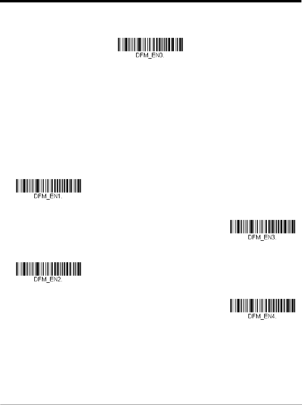
Choose one of the following options. Default = Data Formatter On, Not Required, Keep Prefix/Suffix.
Data Formatter Off
* Data Formatter On,
Not Required,
Keep Prefix/Suffix
Data Formatter On,
Not Required,
Drop Prefix/Suffix
Data Format Required,
Keep Prefix/Suffix
Data Format Required,
Drop Prefix/Suffix
Preliminary draft_1
6 - 13
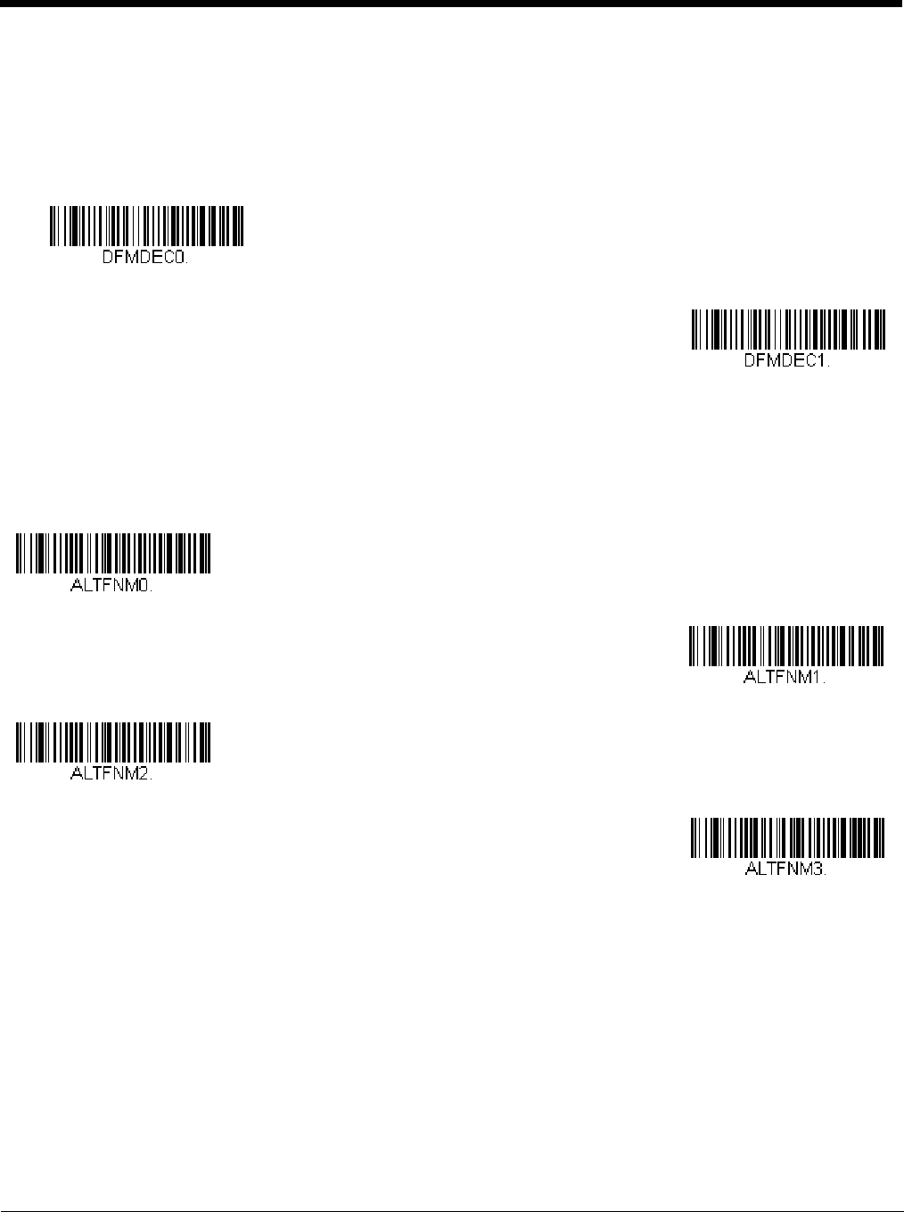
Data Format Non-Match Error Tone
When a bar code is encountered that doesn’t match your required data format, the scanner normally generates an error
tone. However, you may want to continue scanning bar codes without hearing the error tone. If you scan the Data Format
Non-Match Error Tone Off bar code, data that doesn’t conform to your data format is not transmitted, and no error tone will
sound. If you wish to hear the error tone when a non-matching bar code is found, scan the Data Format Non-Match Error
Tone On bar code. Default = Data Format Non-Match Error Tone On.
Primary/Alternate Data Formats
You can save up to four data formats, and switch between these formats. Your primary data format is saved under 0. Your other
three formats are saved under 1, 2, and 3. To set your device to use one of these formats, scan one of the bar codes below.
Single Scan Data Format Change
You can also switch between data formats for a single scan. The next bar code is scanned using an alternate data format,
then reverts to the format you have selected above (either Primary, 1, 2, or 3).
* Data Format Non-Match Error
Tone On
Data Format Non-Match
Error Tone Off
Primary Data Format
Data Format 1
Data Format 2
Data Format 3
Preliminary draft_1
6 - 14
For example, you may have set your device to the data format you saved as Data Format 3. You can switch to Data Format
1 for a single trigger pull by scanning the Single Scan-Data Format 1 bar code below. The next bar code that is scanned
uses Data Format 1, then reverts back to Data Format 3.
Single Scan-Primary
Data Format
Single Scan-Data Format 1
Single Scan-Data Format 2
Single Scan-Data Format 3
Preliminary draft_1

7 - 1
7
Symbologies
This programming section contains the following menu selections. Refer to Chapter 11 for settings and defaults.
All Symbologies
If you want to decode all the symbologies allowable for your scanner, scan the All Symbologies On code. If on the other hand,
you want to decode only a particular symbology, scan All Symbologies Off followed by the On symbol for that particular sym-
bology.
Note: When All Symbologies On is scanned, 2D Postal Codes are not enabled. 2D Postal Codes must be enabled separately.
Message Length Description
You are able to set the valid reading length of some of the bar code symbologies. If the data length of the scanned bar code
doesn’t match the valid reading length, the scanner will issue an error tone. You may wish to set the same value for minimum
and maximum length to force the scanner to read fixed length bar code data. This helps reduce the chances of a misread.
EXAMPLE: Decode only those bar codes with a count of 9-20 characters.
Min. length = 09Max. length = 20
• All Symbologies • Interleaved 2 of 5
• Aztec Code • Korea Post
• China Post (Hong Kong 2 of 5) • Matrix 2 of 5
• Chinese Sensible (Han Xin) Code • MaxiCode
• Codabar • MicroPDF417
• Codablock A • MSI
• Codablock F • NEC 2 of 5
• Code 11 • Postal Codes - 2D
• Code 128 • Postal Codes - Linear
• Code 32 Pharmaceutical (PARAF) • PDF417
• Code 39 • GS1 DataBar Omnidirectional
• Code 93 • QR Code
• Data Matrix • Straight 2 of 5 IATA (two-bar start/stop)
• EAN/JAN-13 • Straight 2 of 5 Industrial (three-bar start/stop)
• EAN/JAN-8 • TCIF Linked Code 39 (TLC39)
• GS1 Composite Codes • Telepen
• GS1 DataBar Expanded • Trioptic Code
• GS1 DataBar Limited • UPC-A
• GS1 DataBar Omnidirectional • UPC-A/EAN-13 with Extended Coupon Code
• GS1 Emulation • UPC-E0
•GS1-128 •UPC-E1
All Symbologies On
All Symbologies Off
Preliminary draft_1
7 - 2
EXAMPLE: Decode only those bar codes with a count of 15 characters.
Min. length = 15Max. length = 15
For a value other than the minimum and maximum message length defaults, scan the bar codes included in the explanation of
the symbology, then scan the digit value of the message length and Save bar codes on the Programming Chart inside the back
cover of this manual. The minimum and maximum lengths and the defaults are included with the respective symbologies.
Codabar
<Default All Codabar Settings>
Codabar On/Off
Codabar Start/Stop Characters
Start/Stop characters identify the leading and trailing ends of the bar code. You may either transmit, or not transmit Start/
Stop characters. Default = Don’t Transmit.
Codabar Check Character
Codabar check characters are created using different “modulos.” You can program the scanner to read only Codabar bar
codes with Modulo 16 check characters. Default = No Check Character.
No Check Character indicates that the scanner reads and transmits bar code data with or without a check character.
When Check Character is set to Validate and Transmit, the scanner will only read Codabar bar codes printed with a check
character, and will transmit this character at the end of the scanned data.
When Check Character is set to Validate, but Don’t Transmit, the unit will only read Codabar bar codes printed with a
check character, but will not transmit the check character with the scanned data.
* On
Off
Transmit
* Don’t Transmit
* No Check Character
Preliminary draft_1
7 - 3
Codabar Concatenation
Codabar supports symbol concatenation. When you enable concatenation, the scanner looks for a Codabar symbol having
a “D” start character, adjacent to a symbol having a “D” stop character. In this case the two messages are concatenated
into one with the “D” characters omitted.
Select Require to prevent the scanner from decoding a single “D” Codabar symbol without its companion. This selection
has no effect on Codabar symbols without Stop/Start D characters.
Codabar Message Length
Scan the bar codes below to change the message length. Refer to Message Length Description (page 7-1) for additional
information. Minimum and Maximum lengths = 2-60. Minimum Default = 4, Maximum Default = 60.
Validate Modulo 16, but
Don’t Transmit
Validate Modulo 16
and Transmit
A123 4D
D5 6 7 8 A
On
* Off
Require
Minimum Message Length
Maximum Message Length
Preliminary draft_1
7 - 4
Code 39
< Default All Code 39 Settings >
Code 39 On/Off
Code 39 Start/Stop Characters
Start/Stop characters identify the leading and trailing ends of the bar code. You may either transmit, or not transmit Start/
Stop characters. Default = Don’t Transmit.
Code 39 Check Character
No Check Character indicates that the scanner reads and transmits bar code data with or without a check character.
When Check Character is set to Validate, but Don’t Transmit, the unit only reads Code 39 bar codes printed with a check
character, but will not transmit the check character with the scanned data.
When Check Character is set to Validate and Transmit, the scanner only reads Code 39 bar codes printed with a check
character, and will transmit this character at the end of the scanned data. Default = No Check Character.
* On
Off
Transmit
* Don’t Transmit
* No Check Character
Validate, but Don’t Transmit
Validate and Transmit
Preliminary draft_1
7 - 5
Code 39 Message Length
Scan the bar codes below to change the message length. Refer to Message Length Description (page 7-1) for additional
information. Minimum and Maximum lengths = 0-48. Minimum Default = 0, Maximum Default = 48.
Code 39 Append
This function allows the scanner to append the data from several Code 39 bar codes together before transmitting them to
the host computer. When the scanner encounters a Code 39 bar code with the append trigger character(s), it buffers Code
39 bar codes until it reads a Code 39 bar code that does not have the append trigger. The data is then transmitted in the
order in which the bar codes were read (FIFO). Default = Off.
Code 32 Pharmaceutical (PARAF)
Code 32 Pharmaceutical is a form of the Code 39 symbology used by Italian pharmacies. This symbology is also known as
PAR AF.
Note: Trioptic Code (page 7-32) must be turned off while scanning Code 32 Pharmaceutical codes.
Minimum Message Length
Maximum Message Length
On
* Off
On
* Off
Preliminary draft_1
7 - 6
Full ASCII
If Full ASCII Code 39 decoding is enabled, certain character pairs within the bar code symbol will be interpreted as a single
character. For example: $V will be decoded as the ASCII character SYN, and /C will be decoded as the ASCII character #.
Default = Off.
Character pairs /M and /N decode as a minus sign and period respectively.
Character pairs /P through /Y decode as 0 through 9.
Code 39 Code Page
Code pages define the mapping of character codes to characters. If the data received does not display with the proper
characters, it may be because the bar code being scanned was created using a code page that is different from the one the
host program is expecting. If this is the case, scan the bar code below, select the code page with which the bar codes were
created (see ISO 2022/ISO 646 Character Replacements on page A-7), and scan the value and the Save bar code from
the Programming Chart on the inside the back cover of this manual. The data characters should then appear properly.
NUL %U DLE $P
SP SPACE
00@%VPP‘%Wp+P
SOH $A DC1 $Q !/A 11AAQQa+Aq+Q
STX $B DC2 $R “/B 22BBRRb+Br+R
ETX $C DC3 $S #/C 33CCSSc+Cs+S
EOT $D DC4 $T $/D 44DDTTd+Dt+T
ENQ $E NAK $U %/E 55EEUUe+Eu+U
ACK $F SYN $V &/F 66FFVVf+Fv+V
BEL $G ETB $W ‘/G77GGWWg+Gw+W
BS $H CAN $X (/H 88HHXXh+Hx+X
HT $I EM $Y )/I 99IIYYi+Iy+Y
LF $J SUB $Z */J :/ZJJZZj+Jz+Z
VT $K ESC %A +/K ;%FKK[%Kk+K{%P
FF $L FS %B ,/L <%GLL\%Ll+L|%Q
CR $M GS %C -- =%HMM]%Mm+M}%R
SO $N RS %D .. >%INN^%Nn+N~%S
SI $O US %E //O ?%JOO_%Oo+ODEL %T
Full ASCII On
* Full ASCII Off
Code 39 Code Page
Preliminary draft_1
7 - 7
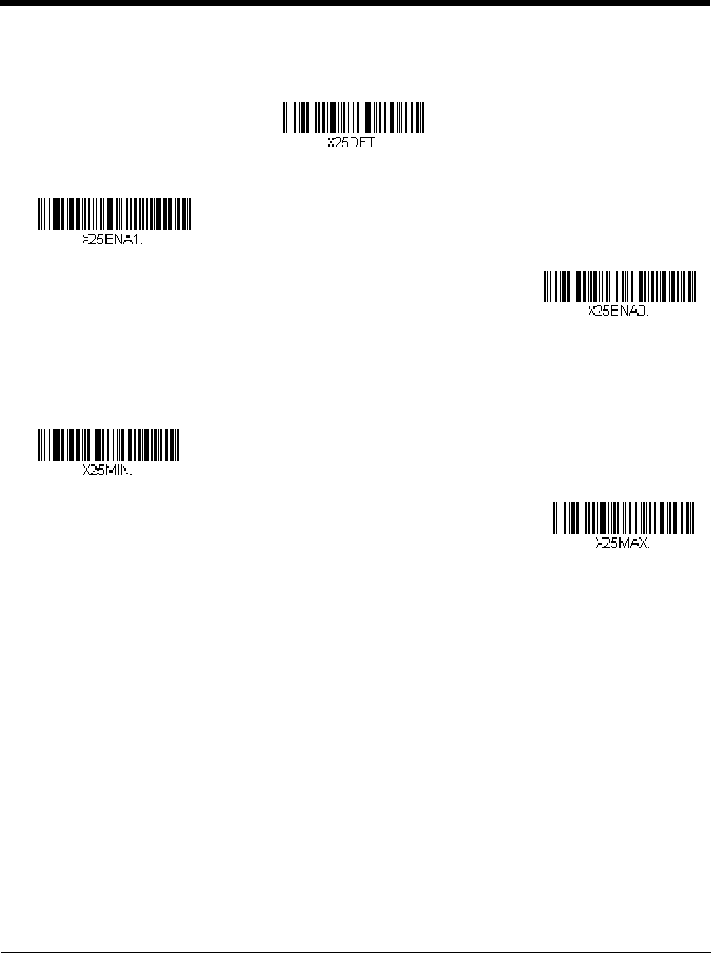
Interleaved 2 of 5
< Default All Interleaved 2 of 5 Settings >
Interleaved 2 of 5 On/Off
Check Digit
No Check Digit indicates that the scanner reads and transmits bar code data with or without a check digit.
When Check Digit is set to Validate, but Don’t Transmit, the unit only reads Interleaved 2 of 5 bar codes printed with a
check digit, but will not transmit the check digit with the scanned data.
When Check Digit is set to Validate and Transmit, the scanner only reads Interleaved 2 of 5 bar codes printed with a
check digit, and will transmit this digit at the end of the scanned data. Default = No Check Digit.
Interleaved 2 of 5 Message Length
Scan the bar codes below to change the message length. Refer to Message Length Description (page 7-1) for additional
information. Minimum and Maximum lengths = 2-80. Minimum Default = 4, Maximum Default = 80.
* On
Off
* No Check Digit
Validate, but Don’t Transmit
Validate and Transmit
Minimum Message Length
Preliminary draft_1
7 - 8
NEC 2 of 5
< Default All NEC 2 of 5 Settings >
NEC 2 of 5 On/Off
Check Digit
No Check Digit indicates that the scanner reads and transmits bar code data with or without a check digit.
When Check Digit is set to Validate, but Don’t Transmit, the unit only reads NEC 2 of 5 bar codes printed with a check
digit, but will not transmit the check digit with the scanned data.
When Check Digit is set to Validate and Transmit, the scanner only reads NEC 2 of 5 bar codes printed with a check digit,
and will transmit this digit at the end of the scanned data. Default = No Check Digit.
Maximum Message Length
* On
Off
* No Check Digit
Validate, but Don’t Transmit
Validate and Transmit
Preliminary draft_1
7 - 9
NEC 2 of 5 Message Length
Scan the bar codes below to change the message length. Refer to Message Length Description (page 7-1) for additional
information. Minimum and Maximum lengths = 2-80. Minimum Default = 4, Maximum Default = 80.
Code 93
< Default All Code 93 Settings >
Code 93 On/Off
Code 93 Message Length
Scan the bar codes below to change the message length. Refer to Message Length Description (page 7-1) for additional
information. Minimum and Maximum lengths = 0-80. Minimum Default = 0, Maximum Default = 80.
Minimum Message Length
Maximum Message Length
* On
Off
Minimum Message Length
Maximum Message Length
Preliminary draft_1
7 - 10
Code 93 Append
This function allows the scanner to append the data from several Code 93 bar codes together before transmitting them to
the host computer. When this function is enabled, the scanner stores those Code 93 bar codes that start with a space
(excluding the start and stop symbols), and does not immediately transmit the data. The scanner stores the data in the
order in which the bar codes are read, deleting the first space from each. The scanner transmits the appended data when
it reads a Code 93 bar code that starts with a character other than a space. Default = Off.
Code 93 Code Page
Code pages define the mapping of character codes to characters. If the data received does not display with the proper
characters, it may be because the bar code being scanned was created using a code page that is different from the one the
host program is expecting. If this is the case, scan the bar code below, select the code page with which the bar codes were
created (see ISO 2022/ISO 646 Character Replacements on page A-7), and scan the value and the Save bar code from
the Programming Chart on the inside the back cover of this manual. The data characters should then appear properly.
On
* Off
Code 93 Code Page
Preliminary draft_1
7 - 11
Straight 2 of 5 Industrial (three-bar start/stop)
<Default All Straight 2 of 5 Industrial Settings>
Straight 2 of 5 Industrial On/Off
Straight 2 of 5 Industrial Message Length
Scan the bar codes below to change the message length. Refer to Message Length Description (page 7-1) for additional
information. Minimum and Maximum lengths = 1-48. Minimum Default = 4, Maximum Default = 48.
On
* Off
Minimum Message Length
Maximum Message Length
Preliminary draft_1
7 - 12
Straight 2 of 5 IATA (two-bar start/stop)
<Default All Straight 2 of 5 IATA Settings>
Straight 2 of 5 IATA On/Off
Straight 2 of 5 IATA Message Length
Scan the bar codes below to change the message length. Refer to Message Length Description (page 7-1) for additional
information. Minimum and Maximum lengths = 1-48. Minimum Default = 4, Maximum Default = 48.
On
* Off
Minimum Message Length
Maximum Message Length
Preliminary draft_1
7 - 13
Matrix 2 of 5
<Default All Matrix 2 of 5 Settings>
Matrix 2 of 5 On/Off
Matrix 2 of 5 Message Length
Scan the bar codes below to change the message length. Refer to Message Length Description (page 7-1) for additional
information. Minimum and Maximum lengths = 1-80. Minimum Default = 4, Maximum Default = 80.
On
* Off
Minimum Message Length
Maximum Message Length
Preliminary draft_1
7 - 14
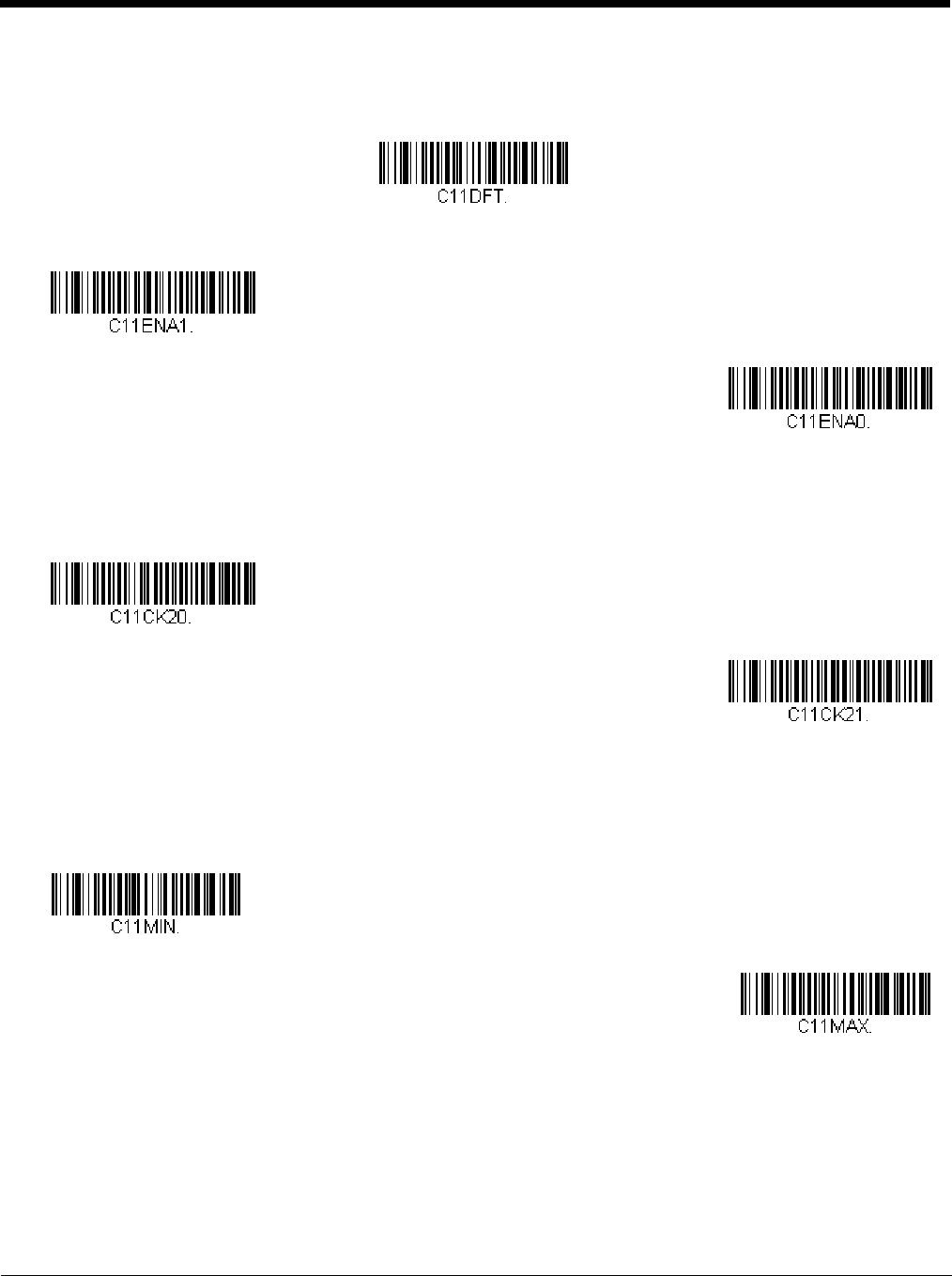
Code 11
<Default All Code 11 Settings>
Code 11 On/Off
Check Digits Required
This option sets whether 1 or 2 check digits are required with Code 11 bar codes. Default = Two Check Digits.
Code 11 Message Length
Scan the bar codes below to change the message length. Refer to Message Length Description (page 7-1) for additional
information. Minimum and Maximum lengths = 1-80. Minimum Default = 4, Maximum Default = 80.
On
* Off
One Check Digit
* Two Check Digits
Minimum Message Length
Maximum Message Length
Preliminary draft_1
7 - 15
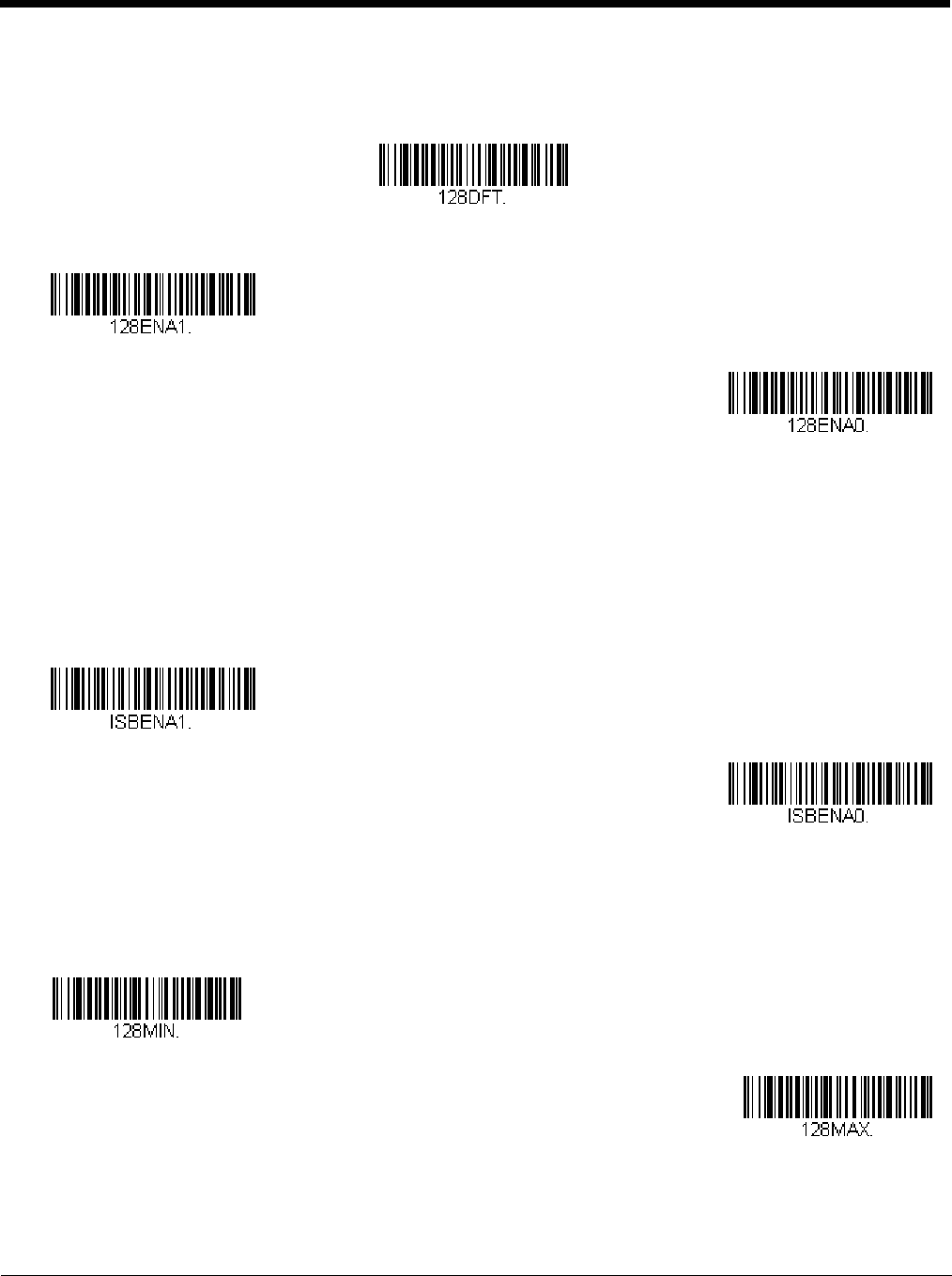
Code 128
<Default All Code 128 Settings>
Code 128 On/Off
ISBT 128 Concatenation
In 1994 the International Society of Blood Transfusion (ISBT) ratified a standard for communicating critical blood informa-
tion in a uniform manner. The use of ISBT formats requires a paid license. The ISBT 128 Application Specification
describes 1) the critical data elements for labeling blood products, 2) the current recommendation to use Code 128 due to
its high degree of security and its space-efficient design, 3) a variation of Code 128 that supports concatenation of neigh-
boring symbols, and 4) the standard layout for bar codes on a blood product label. Use the bar codes below to turn concat-
enation on or off. Default =Off.
Code 128 Message Length
Scan the bar codes below to change the message length. Refer to Message Length Description (page 7-1) for additional
information. Minimum and Maximum lengths = 0-80. Minimum Default = 0, Maximum Default = 80.
* On
Off
On
* Off
Minimum Message Length
Maximum Message Length
Preliminary draft_1
7 - 16
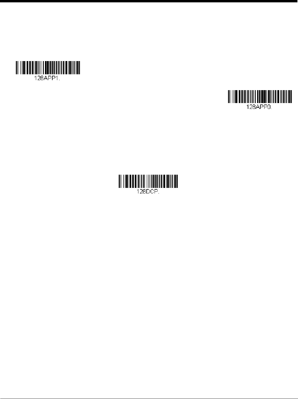
Code 128 Append
This function allows the scanner to append the data from several Code 128 bar codes together before transmitting them to
the host computer. When the scanner encounters a Code 128 bar code with the append trigger character(s), it buffers
Code 128 bar codes until it reads a Code 128 bar code that does not have the append trigger. The data is then transmitted
in the order in which the bar codes were read (FIFO). Default = On.
Code 128 Code Page
Code pages define the mapping of character codes to characters. If the data received does not display with the proper
characters, it may be because the bar code being scanned was created using a code page that is different from the one the
host program is expecting. If this is the case, scan the bar code below, select the code page with which the bar codes were
created (see ISO 2022/ISO 646 Character Replacements on page A-7), and scan the value and the Save bar code from
the Programming Chart on the inside the back cover of this manual. The data characters should then appear properly.
* On
Off
Code 128 Code Page
Preliminary draft_1
7 - 17
GS1-128
<Default All GS1-128 Settings>
GS1-128 On/Off
GS1-128 Message Length
Scan the bar codes below to change the message length. Refer to Message Length Description (page 7-1) for additional
information. Minimum and Maximum lengths = 1-80. Minimum Default = 1, Maximum Default = 80.
* On
Off
Minimum Message Length
Maximum Message Length
Preliminary draft_1
7 - 18
Telepen
<Default All Telepen Settings>
Telepen On/Off
Telepen Output
Using AIM Telepen Output, the scanner reads symbols with start/stop pattern 1 and decodes them as standard full ASCII
(start/stop pattern 1). When Original Telepen Output is selected, the scanner reads symbols with start/stop pattern 1 and
decodes them as compressed numeric with optional full ASCII (start/stop pattern 2). Default = AIM Telepen Output.
Telepen Message Length
Scan the bar codes below to change the message length. Refer to Message Length Description (page 7-1) for additional
information. Minimum and Maximum lengths = 1-60. Minimum Default = 1, Maximum Default = 60.
On
* Off
* AIM Telepen Output
Original Telepen Output
Minimum Message Length
Maximum Message Length
Preliminary draft_1
7 - 19
UPC-A
<Default All UPC-A Settings>
UPC-A On/Off
Note: To convert UPC-A bar codes to EAN-13, see Convert UPC-A to EAN-13 on page 7-24.
UPC-A Check Digit
This selection allows you to specify whether the check digit should be transmitted at the end of the scanned data or not.
Default = On.
UPC-A Number System
The numeric system digit of a U.P.C. symbol is normally transmitted at the beginning of the scanned data, but the unit can
be programmed so it will not transmit it. Default = On.
* On
Off
* On
Off
* On
Off
Preliminary draft_1
7 - 20
UPC-A Addenda
This selection adds 2 or 5 digits to the end of all scanned UPC-A data.
Default = Off for both 2 Digit and 5 Digit Addenda.
UPC-A Addenda Required
When Required is scanned, the scanner will only read UPC-A bar codes that have addenda. You must then turn on a 2 or
5 digit addenda listed on page 7-20. Default = Not Required.
UPC-A Addenda Separator
When this feature is on, there is a space between the data from the bar code and the data from the addenda. When turned
off, there is no space. Default = On.
2 Digit Addenda On
* 2 Digit Addenda Off
5 Digit Addenda On
* 5 Digit Addenda Off
Required
* Not Required
* On
Off
Preliminary draft_1
7 - 21
UPC-A/EAN-13 with Extended Coupon Code
Use the following codes to enable or disable UPC-A and EAN-13 with Extended Coupon Code. When left on the default setting
(Off), the scanner treats Coupon Codes and Extended Coupon Codes as single bar codes.
If you scan the Allow Concatenation code, when the scanner sees the coupon code and the extended coupon code in a single
scan, it transmits both as separate symbologies. Otherwise, it transmits the first coupon code it reads.
If you scan the Require Concatenation code, the scanner must see and read the coupon code and extended coupon code in a
single read to transmit the data. No data is output unless both codes are read. Default = Off.
Coupon GS1 DataBar Output
If you scan coupons that have both UPC and GS1 DataBar codes, you may wish to scan and output only the data from the GS1
DataBar code. Scan the GS1 Output On code below to scan and output only the GS1 DataBar code data. Default = GS1 Out-
put Off.
* Off
Allow Concatenation
Require Concatenation
* GS1 Output Off
GS1 Output On
Preliminary draft_1
7 - 22
UPC-E0
<Default All UPC-E Settings>
UPC-E0 On/Off
Most U.P.C. bar codes lead with the 0 number system. To read these codes, use the UPC-E0 On selection. If you need to
read codes that lead with the 1 number system, use UPC-E1 (page 7-24). Default = On.
UPC-E0 Expand
UPC-E Expand expands the UPC-E code to the 12 digit, UPC-A format. Default = Off.
UPC-E0 Addenda Required
When Required is scanned, the scanner will only read UPC-E bar codes that have addenda. Default = Not Required.
* UPC-E0 On
UPC-E0 Off
On
* Off
Required
* Not Required
Preliminary draft_1
7 - 23
UPC-E0 Addenda Separator
When this feature is On, there is a space between the data from the bar code and the data from the addenda. When turned
Off, there is no space. Default = On.
UPC-E0 Check Digit
Check Digit specifies whether the check digit should be transmitted at the end of the scanned data or not. Default = On.
UPC-E0 Leading Zero
This feature allows the transmission of a leading zero (0) at the beginning of scanned data. To prevent transmission, scan
Off. Default = On.
UPC-E0 Addenda
This selection adds 2 or 5 digits to the end of all scanned UPC-E data. Default = Off for both 2 Digit and 5 Digit Addenda.
* On
Off
* On
Off
* On
Off
2 Digit Addenda On
* 2 Digit Addenda Off
Preliminary draft_1
7 - 24
UPC-E1
Most U.P.C. bar codes lead with the 0 number system. For these codes, use UPC-E0 (page 7-22). If you need to read codes
that lead with the 1 number system, use the UPC-E1 On selection. Default = Off.
EAN/JAN-13
<Default All EAN/JAN Settings>
EAN/JAN-13 On/Off
Convert UPC-A to EAN-13
When UPC-A Converted to EAN-13 is selected, UPC-A bar codes are converted to 13 digit EAN-13 codes by adding a
zero to the front. When Do not Convert UPC-A is selected, UPC-A codes are read as UPC-A.
5 Digit Addenda On
* 5 Digit Addenda Off
UPC-E1 On
* UPC-E1 Off
* On
Off
UPC-A Converted to EAN-13
Preliminary draft_1
7 - 25
EAN/JAN-13 Check Digit
This selection allows you to specify whether the check digit should be transmitted at the end of the scanned data or not.
Default = On.
EAN/JAN-13 Addenda
This selection adds 2 or 5 digits to the end of all scanned EAN/JAN-13 data. Default = Off for both 2 Digit and 5 Digit
Addenda.
EAN/JAN-13 Addenda Required
When Required is scanned, the scanner will only read EAN/JAN-13 bar codes that have addenda. Default = Not Required.
* Do not Convert UPC-A
* On
Off
2 Digit Addenda On
* 2 Digit Addenda Off
5 Digit Addenda On
* 5 Digit Addenda Off
Required
Preliminary draft_1
7 - 26
EAN/JAN-13 Addenda Separator
When this feature is On, there is a space between the data from the bar code and the data from the addenda. When turned
Off, there is no space. Default = On.
Note: If you want to enable or disable EAN13 with Extended Coupon Code, refer to UPC-A/EAN-13 with Extended Coupon
Code (page 7-21).
ISBN Translate
When On is scanned, EAN-13 Bookland symbols are translated into their equivalent ISBN number format. Default = Off.
* Not Required
* On
Off
On
* Off
Preliminary draft_1
7 - 27
EAN/JAN-8
<Default All EAN/JAN-8 Settings>
EAN/JAN-8 On/Off
EAN/JAN-8 Check Digit
This selection allows you to specify whether the check digit should be transmitted at the end of the scanned data or not.
Default = On.
EAN/JAN-8 Addenda
This selection adds 2 or 5 digits to the end of all scanned EAN/JAN-8 data. Default = Off for both 2 Digit and 5 Digit
Addenda.
* On
Off
* On
Off
2 Digit Addenda On
* 2 Digit Addenda Off
5 Digit Addenda On
Preliminary draft_1
7 - 28
EAN/JAN-8 Addenda Required
When Required is scanned, the scanner will only read EAN/JAN-8 bar codes that have addenda. Default = Not Required.
EAN/JAN-8 Addenda Separator
When this feature is On, there is a space between the data from the bar code and the data from the addenda. When turned
Off, there is no space. Default = On.
* 5 Digit Addenda Off
Required
* Not Required
* On
Off
Preliminary draft_1
7 - 29
MSI
<Default All MSI Settings>
MSI On/Off
MSI Check Character
Different types of check characters are used with MSI bar codes. You can program the scanner to read MSI bar codes with
Type 10 check characters. Default = Validate Type 10, but Don’t Transmit.
When Check Character is set to Validate Type 10/11 and Transmit, the scanner will only read MSI bar codes printed with
the specified type check character(s), and will transmit the character(s) at the end of the scanned data.
When Check Character is set to Validate Type 10/11, but Don’t Transmit, the unit will only read MSI bar codes printed
with the specified type check character(s), but will not transmit the check character(s) with the scanned data.
On
* Off
* Validate Type 10, but Don’t
Transmit
Validate Type 10 and Transmit
Validate 2 Type 10 Characters,
but Don’t Transmit
Validate 2 Type 10 Characters
and Transmit
Validate Type 11 then Type 10
Character, but Don’t Transmit
Preliminary draft_1
7 - 30
MSI Message Length
Scan the bar codes below to change the message length. Refer to Message Length Description (page 7-1) for additional
information. Minimum and Maximum lengths = 4-48. Minimum Default = 4, Maximum Default = 48.
Validate Type 11 then
Type 10 Character and Transmit
Disable MSI Check Characters
Minimum Message Length
Maximum Message Length
Preliminary draft_1
7 - 31
GS1 DataBar Omnidirectional
< Default All GS1 DataBar Omnidirectional Settings >
GS1 DataBar Omnidirectional On/Off
GS1 DataBar Limited
< Default All GS1 DataBar Limited Settings >
GS1 DataBar Limited On/Off
* On
Off
* On
Off
Preliminary draft_1
7 - 32
GS1 DataBar Expanded
< Default All GS1 DataBar Expanded Settings >
GS1 DataBar Expanded On/Off
GS1 DataBar Expanded Message Length
Scan the bar codes below to change the message length. Refer to Message Length Description (page 7-1) for additional
information. Minimum and Maximum lengths = 4-74. Minimum Default = 4, Maximum Default = 74.
Trioptic Code
Note: If you are going to scan Code 32 Pharmaceutical codes (page 7-5), Trioptic Code must be off.
Trioptic Code is used for labeling magnetic storage media.
* On
Off
Minimum Message Length
Maximum Message Length
On
* Off
Preliminary draft_1
7 - 33
Codablock A
<Default All Codablock A Settings>
Codablock A On/Off
Codablock A Message Length
Scan the bar codes below to change the message length. Refer to Message Length Description (page 7-1) for additional
information. Minimum and Maximum lengths = 1-600. Minimum Default = 1, Maximum Default = 600.
On
* Off
Minimum Message Length
Maximum Message Length
Preliminary draft_1
7 - 34
Codablock F
<Default All Codablock F Settings>
Codablock F On/Off
Codablock F Message Length
Scan the bar codes below to change the message length. Refer to Message Length Description (page 7-1) for additional
information. Minimum and Maximum lengths = 1-2048. Minimum Default = 1, Maximum Default = 2048.
On
* Off
Minimum Message Length
Maximum Message Length
Preliminary draft_1
7 - 35
PDF417
< Default All PDF417 Settings >
PDF417 On/Off
PDF417 Message Length
Scan the bar codes below to change the message length. Refer to Message Length Description (page 7-1) for additional
information. Minimum and Maximum lengths = 1-2750. Minimum Default = 1, Maximum Default = 2750.
MacroPDF417
MacroPDF417 is an implementation of PDF417 capable of encoding very large amounts of data into multiple PDF417 bar
codes. When this selection is enabled, these multiple bar codes are assembled into a single data string. Default = On.
* On
Off
Minimum Message Length
Maximum Message Length
* On
Off
Preliminary draft_1
7 - 36
MicroPDF417
< Default All MicroPDF417 Settings >
MicroPDF417 On/Off
MicroPDF417 Message Length
Scan the bar codes below to change the message length. Refer to Message Length Description (page 7-1) for additional
information. Minimum and Maximum lengths = 1-366. Minimum Default = 1, Maximum Default = 366.
GS1 Composite Codes
Linear codes are combined with a unique 2D composite component to form a new class called GS1 Composite symbology.
GS1 Composite symbologies allow for the co-existence of symbologies already in use. Default = Off.
On
* Off
Minimum Message Length
Maximum Message Length
On
* Off
Preliminary draft_1
7 - 37
UPC/EAN Version
Scan the UPC/EAN Version On bar code to decode GS1 Composite symbols that have a U.P.C. or an EAN linear compo-
nent. (This does not affect GS1 Composite symbols with a GS1-128 or GS1 linear component.) Default = UPC/EAN Ver-
sion Off.
Note: If you scan coupons that have both UPC and GS1 DataBar codes, you may wish to scan and output only the data from
the GS1 DataBar code. See Coupon GS1 DataBar Output (page 7-21) for further information.
GS1 Composite Code Message Length
Scan the bar codes below to change the message length. Refer to Message Length Description (page 7-1) for additional
information. Minimum and Maximum lengths = 1-2435. Minimum Default = 1, Maximum Default = 2435.
GS1 Emulation
The scanner can automatically format the output from any GS1 data carrier to emulate what would be encoded in an equivalent
GS1-128 or GS1 DataBar symbol. GS1 data carriers include UPC-A and UPC-E, EAN-13 and EAN-8, ITF-14, GS1-128, and
GS1-128 DataBar and GS1 Composites. (Any application that accepts GS1 data can be simplified since it only needs to recog-
nize one data carrier type.)
If GS1-128 Emulation is scanned, all retail codes (U.P.C., UPC-E, EAN8, EAN13) are expanded out to 16 digits. If the AIM ID
is enabled, the value will be the GS1-128 AIM ID, ]C1 (see Symbology Charts on page A-1).
If GS1 DataBar Emulation is scanned, all retail codes (U.P.C., UPC-E, EAN8, EAN13) are expanded out to 16 digits. If the AIM
ID is enabled, the value will be the GS1-DataBar AIM ID, ]em (see Symbology Charts on page A-1).
If GS1 Code Expansion Off is scanned, retail code expansion is disabled, and UPC-E expansion is controlled by the UPC-E0
Expand (page 7-22) setting. If the AIM ID is enabled, the value will be the GS1-128 AIM ID, ]C1 (see Symbology Charts on
page A-1).
If EAN8 to EAN13 Conversion is scanned, all EAN8 bar codes are converted to EAN13 format.
Default = GS1 Emulation Off.
UPC/EAN Version On
* UPC/EAN Version Off
Minimum Message Length
Maximum Message Length
GS1-128 Emulation
Preliminary draft_1
7 - 38
TCIF Linked Code 39 (TLC39)
This code is a composite code since it has a Code 39 linear component and a MicroPDF417 stacked code component. All bar
code readers are capable of reading the Code 39 linear component. The MicroPDF417 component can only be decoded if
TLC39 On is selected. The linear component may be decoded as Code 39 even if TLC39 is off. Default = Off.
QR Code
< Default All QR Code Settings >
QR Code On/Off
This selection applies to both QR Code and Micro QR Code.
GS1 DataBar Emulation
GS1 Code Expansion Off
EAN8 to EAN13 Conversion
* GS1 Emulation Off
On
* Off
* On
Off
Preliminary draft_1
7 - 39
QR Code Message Length
Scan the bar codes below to change the message length. Refer to Message Length Description (page 7-1) for additional
information. Minimum and Maximum lengths = 1-7089. Minimum Default = 1, Maximum Default = 7089.
QR Code Append
This function allows the scanner to append the data from several QR Code bar codes together before transmitting them to
the host computer. When the scanner encounters an QR Code bar code with the append trigger character(s), it buffers the
number of QR Code bar codes determined by information encoded in those bar codes. Once the proper number of codes
is reached, the data is output in the order specified in the bar codes. Default = On.
QR Code Page
QR Code pages define the mapping of character codes to characters. If the data received does not display with the proper
characters, it may be because the bar code being scanned was created using a code page that is different from the one the
host program is expecting. If this is the case, scan the bar code below, select the code page with which the bar codes were
created (see ISO 2022/ISO 646 Character Replacements on page A-7), and scan the value and the Save bar code from
the Programming Chart on the inside the back cover of this manual. The data characters should then appear properly.
Minimum Message Length
Maximum Message Length
* On
Off
QR Code Page
Preliminary draft_1
7 - 40
Data Matrix
< Default All Data Matrix Settings >
Data Matrix On/Off
Data Matrix Message Length
Scan the bar codes below to change the message length. Refer to Message Length Description (page 7-1) for additional
information. Minimum and Maximum lengths = 1-3116. Minimum Default = 1, Maximum Default = 3116.
Data Matrix Append
This function allows the scanner to append the data from several Data Matrix bar codes together before transmitting them
to the host computer. When the scanner encounters an Data Matrix bar code with the append trigger character(s), it buf-
fers the number of Data Matrix bar codes determined by information encoded in those bar codes. Once the proper number
of codes is reached, the data is output in the order specified in the bar codes. Default = On.
Data Matrix Code Page
Data Matrix Code pages define the mapping of character codes to characters. If the data received does not display with the
proper characters, it may be because the bar code being scanned was created using a code page that is different from the
one the host program is expecting. If this is the case, scan the bar code below, select the code page with which the bar
* On
Off
Minimum Message Length
Maximum Message Length
* On
Off
Preliminary draft_1
7 - 41
codes were created (see ISO 2022/ISO 646 Character Replacements on page A-7), and scan the value and the Save bar
code from the Programming Chart on the inside the back cover of this manual. The data characters should then appear
properly.
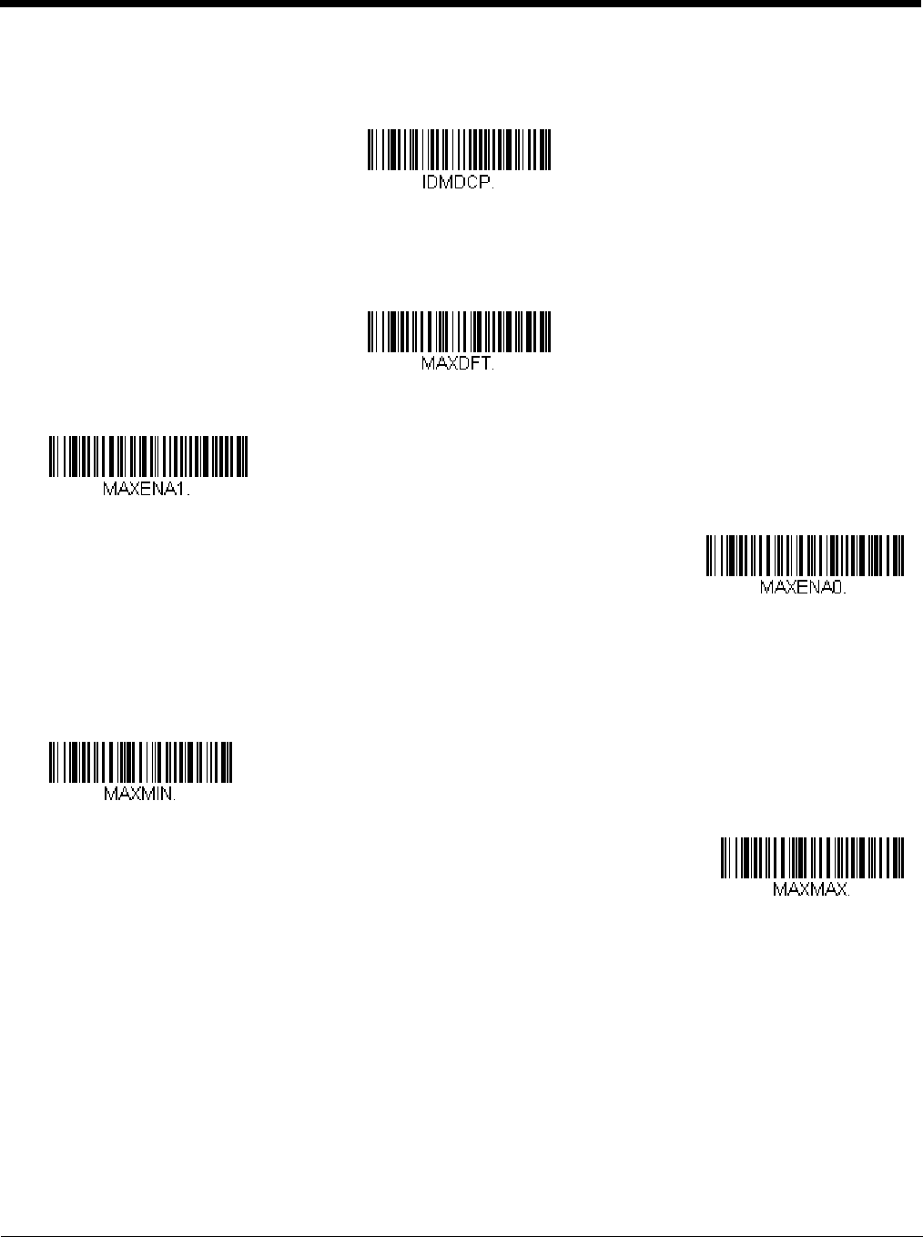
MaxiCode
< Default All MaxiCode Settings >
MaxiCode On/Off
MaxiCode Message Length
Scan the bar codes below to change the message length. Refer to Message Length Description (page 7-1) for additional
information. Minimum and Maximum lengths = 1-150. Minimum Default = 1, Maximum Default = 150.
Data Matrix Code Page
On
* Off
Minimum Message Length
Maximum Message Length
Preliminary draft_1
7 - 42
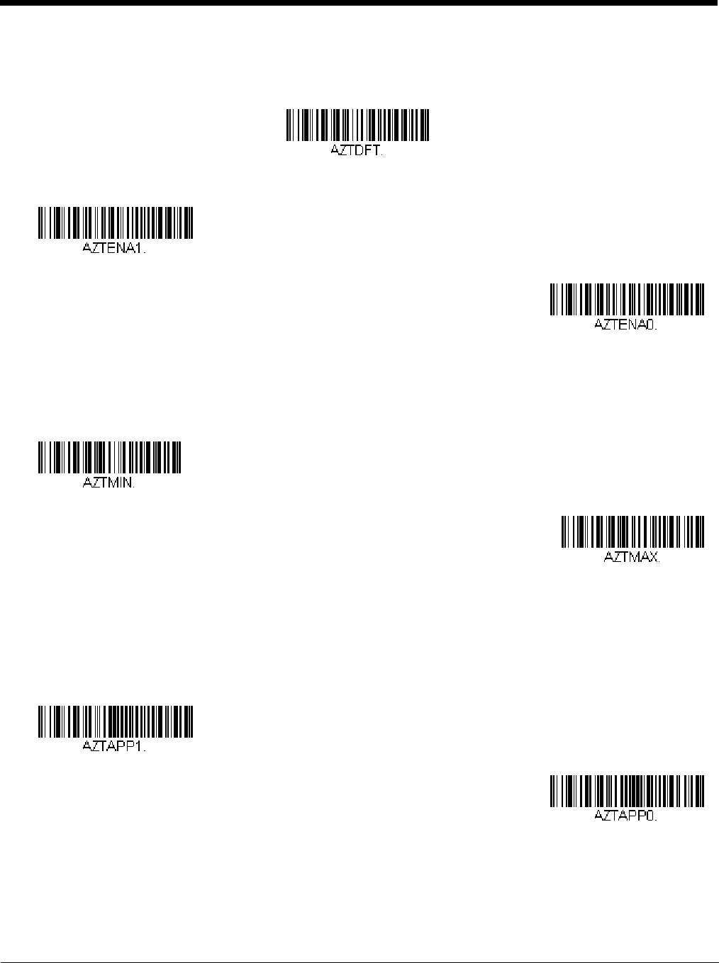
Aztec Code
< Default All Aztec Code Settings >
Aztec Code On/Off
Aztec Code Message Length
Scan the bar codes below to change the message length. Refer to Message Length Description (page 7-1) for additional
information. Minimum and Maximum lengths = 1-3832. Minimum Default = 1, Maximum Default = 3832.
Aztec Append
This function allows the scanner to append the data from several Aztec bar codes together before transmitting them to the
host computer. When the scanner encounters an Aztec bar code with the append trigger character(s), it buffers the number
of Aztec bar codes determined by information encoded in those bar codes. Once the proper number of codes is reached,
the data is output in the order specified in the bar codes. Default = On.
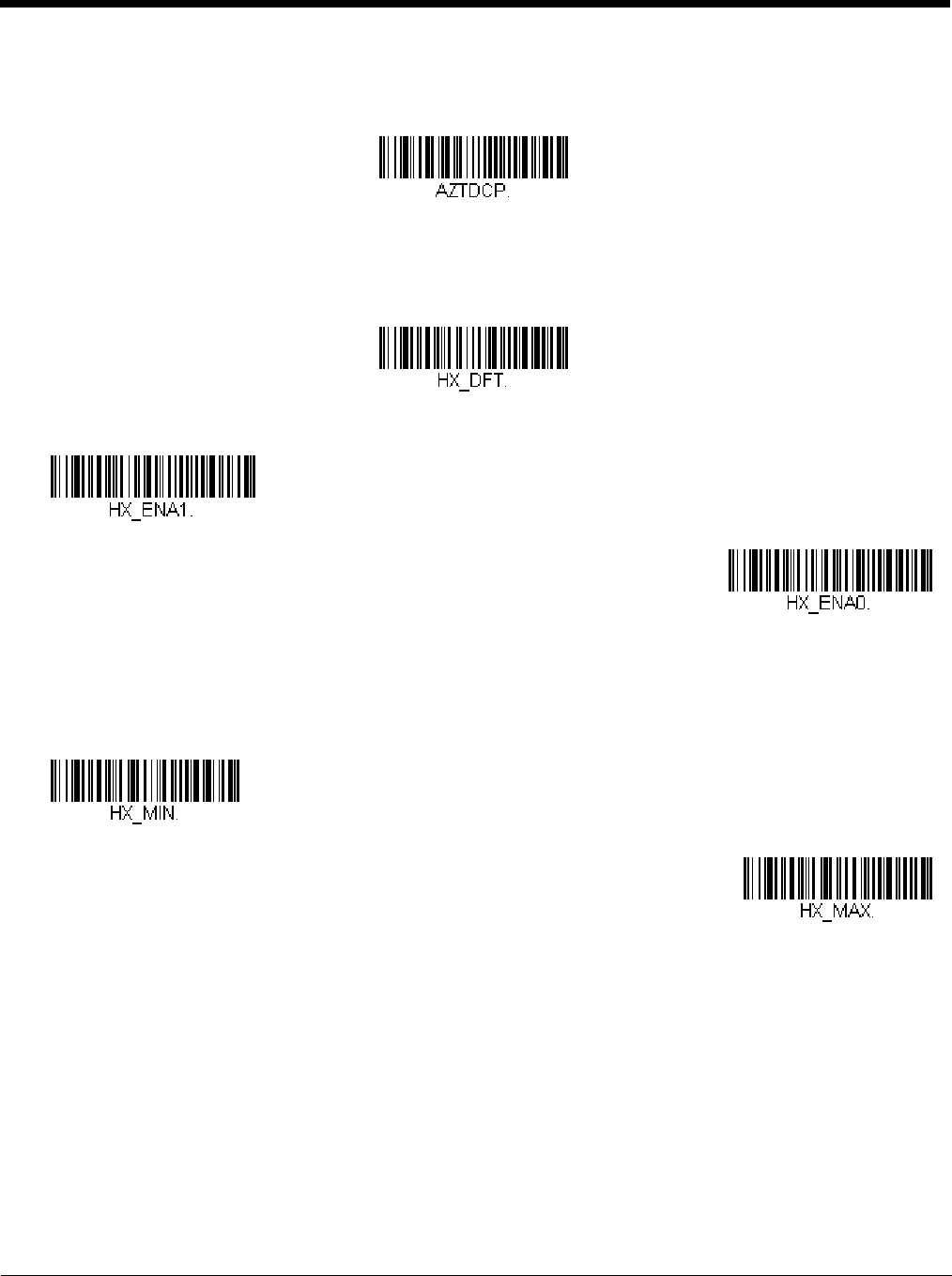
Aztec Code Page
Aztec Code pages define the mapping of character codes to characters. If the data received does not display with the
proper characters, it may be because the bar code being scanned was created using a code page that is different from the
one the host program is expecting. If this is the case, scan the bar code below, select the code page with which the bar
* On
Off
Minimum Message Length
Maximum Message Length
* On
Off
Preliminary draft_1
7 - 43
codes were created (see ISO 2022/ISO 646 Character Replacements on page A-7), and scan the value and the Save bar
code from the Programming Chart on the inside the back cover of this manual. The data characters should then appear
properly.
Chinese Sensible (Han Xin) Code
< Default All Han Xin Settings >
Han Xin Code On/Off
Han Xin Code Message Length
Scan the bar codes below to change the message length. Refer to Message Length Description (page 7-1) for additional
information. Minimum and Maximum lengths = 1-7833. Minimum Default = 1, Maximum Default = 7833.
Aztec Code Page
On
* Off
Minimum Message Length
Maximum Message Length
Preliminary draft_1
7 - 44
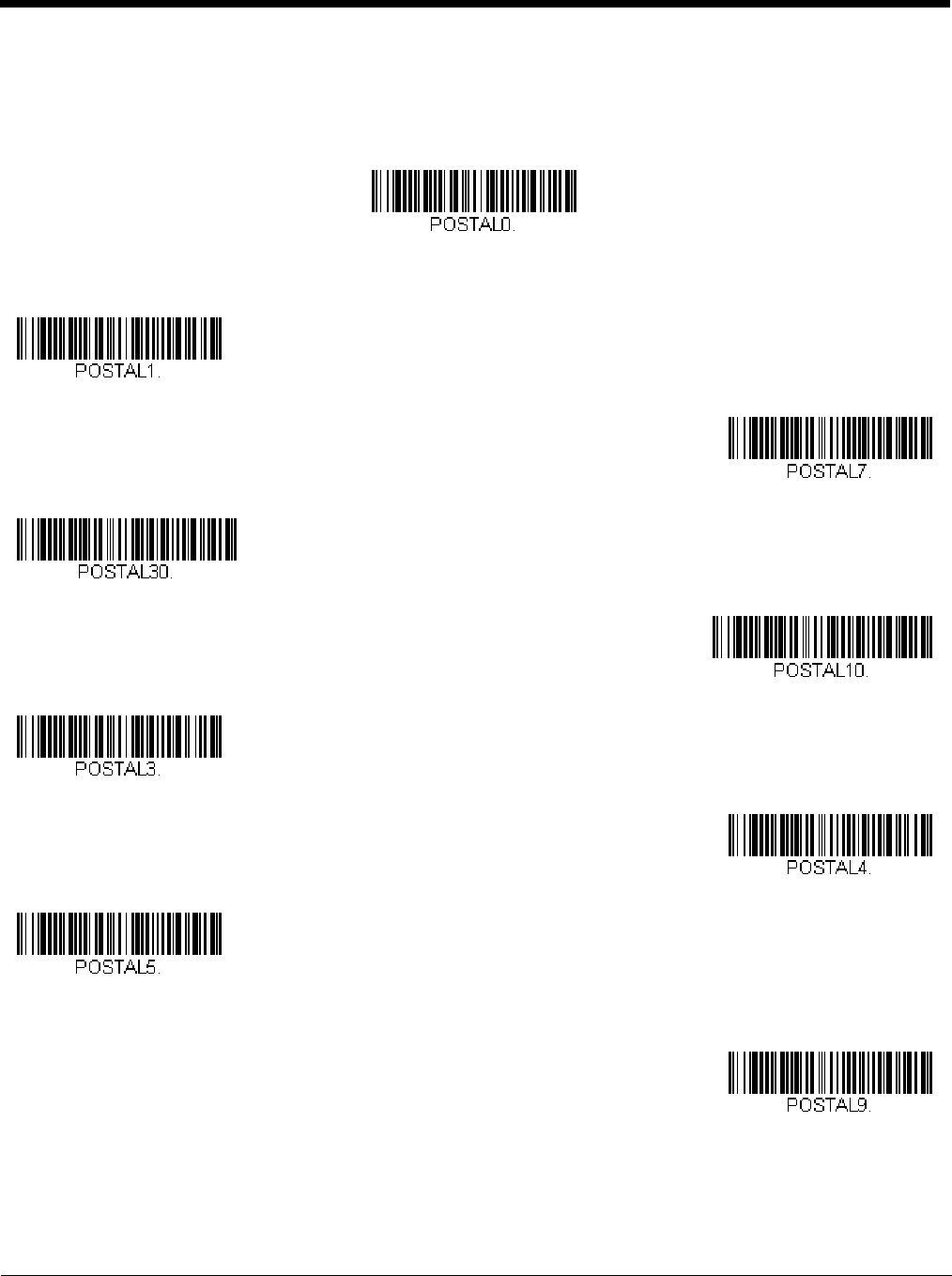
Postal Codes - 2D
The following lists the possible 2D postal codes, and 2D postal code combinations that are allowed. Only one 2D postal code
selection can be active at a time. If you scan a second 2D postal code selection, the first selection is overwritten. Default = 2D
Postal Codes Off.
Single 2D Postal Codes:
* 2D Postal Codes Off
Australian Post On
British Post On
Canadian Post On
Intelligent Mail Bar Code On
Japanese Post On
KIX Post On
Planet Code On
Also see Planet Code
Check Digit, page 7-47.
Postal-4i On
Preliminary draft_1
7 - 45
Combination 2D Postal Codes:
Postnet On
Also see Postnet Check
Digit, page 7-47.
Postnet with B and B’ Fields On
InfoMail On
InfoMail and British
Post On
Intelligent Mail Bar Code and
Postnet with B and B’ Fields On
Postnet and
Postal-4i On
Postnet and
Intelligent Mail Bar Code On
Postal-4i and
Intelligent Mail Bar Code On
Postal-4i and
Postnet with B and B’ Fields On
Planet Code and
Postnet On
Preliminary draft_1
7 - 46
Planet Code and
Postnet with B and B’ Fields On
Planet Code and
Postal-4i On
Planet Code and
Intelligent Mail Bar Code On
Planet Code,
Postnet, and
Postal-4i On
Planet Code,
Postnet, and
Intelligent Mail Bar Code On
Planet Code,
Postal-4i, and
Intelligent Mail Bar Code On
Postnet,
Postal-4i, and
Intelligent Mail Bar Code On
Planet Code,
Postal-4i, and
Postnet with B and B’ Fields On
Planet Code,
Intelligent Mail Bar Code, and
Postnet with B and B’ Fields On
Postal-4i,
Intelligent Mail Bar Code, and
Postnet with B and B’ Fields On
Preliminary draft_1
7 - 47
Planet Code Check Digit
This selection allows you to specify whether the check digit should be transmitted at the end of Planet Code data. Default
= Don’t Transmit.
Postnet Check Digit
This selection allows you to specify whether the check digit should be transmitted at the end of Postnet data. Default =
Don’t Transmit.
Australian Post Interpretation
This option controls what interpretation is applied to customer fields in Australian 4-State symbols.
Bar Output lists the bar patterns in “0123” format.
Numeric N Table causes that field to be interpreted as numeric data using the N Table.
Alphanumeric C Table causes the field to be interpreted as alphanumeric data using the C Table. Refer to the Australian
Post Specification Tables.
Planet Code,
Postal-4i,
Intelligent Mail Bar Code, and
Postnet On
Planet Code,
Postal-4i,
Intelligent Mail Bar Code, and
Postnet with B and B’ Fields On
Transmit Check Digit
* Don’t Transmit Check Digit
Transmit Check Digit
* Don’t Transmit Check Digit
Preliminary draft_1
7 - 48
Combination C and N Tables causes the field to be interpreted using either the C or N Tables.
Postal Codes - Linear
The following lists linear postal codes. Any combination of linear postal code selections can be active at a time.
China Post (Hong Kong 2 of 5)
<Default All China Post (Hong Kong 2 of 5) Settings>
China Post (Hong Kong 2 of 5) On/Off
China Post (Hong Kong 2 of 5) Message Length
Scan the bar codes below to change the message length. Refer to Message Length Description (page 7-1) for addi-
tional information. Minimum and Maximum lengths = 2-80. Minimum Default = 4, Maximum Default = 80.
* Bar Output
Numeric N Table
Alphanumeric C Table
Combination C and N Tables
On
* Off
Minimum Message Length
Preliminary draft_1
7 - 49
Korea Post
<Default All Korea Post Settings>
Korea Post
Korea Post Message Length
Scan the bar codes below to change the message length. Refer to Message Length Description (page 7-1) for addi-
tional information. Minimum and Maximum lengths = 2-80. Minimum Default = 4, Maximum Default = 48.
Korea Post Check Digit
This selection allows you to specify whether the check digit should be transmitted at the end of the scanned data.
Default = Don’t Transmit.
Maximum Message Length
On
* Off
Minimum Message Length
Maximum Message Length
Transmit Check Digit
* Don’t Transmit Check Digit
Preliminary draft_1

7 - 50
Preliminary draft_1

8 - 1
8
Imaging Commands
The scanner is like a digital camera in the way it captures, manipulates, and transfers images. The following commands allow
you to alter the way the scanner performs these functions.
Note: If you are using the scanner in a stand, you must set the In-Stand Sensor Mode to Off in order to take images (see In-
Stand Sensor Mode on page 4-10).
Single-Use Basis
Imaging Commands with their modifiers send instructions to the scanner on a single-use basis, and take effect for a single
image capture. Once that capture is complete, the scanner reverts to its imaging default settings. If you want to permanently
change a setting, you must use the serial default commands (see Chapter 11). When the serial default command is used, that
selection becomes the new, permanent setting for the scanner.
Command Syntax
Multiple modifiers and commands can be issued within one sequence. If additional modifiers are to be applied to the same
command, just add the modifiers to that command. For example, to add 2 modifiers to the Image Snap command, such as set-
ting the Imaging Style to 1P and the Wait for Trigger to 1T, you would enter IMGSNP1P1T.
Note: After processing an image capture command (IMGSNP or IMGBOX), you must follow it with an IMGSHP command if you
want to see it on your terminal.
To add a command to a sequence, each new command is separated with a semicolon. For example, to add the Image Ship
command to the above sequence, you would enter IMGSNP1P1T;IMGSHP.
The imaging commands are:
Image Snap - IMGSNP (page 8-1)
Image Ship - IMGSHP (page 8-3)
Intelligent Signature Capture - IMGBOX (page 8-10)
The modifiers for each of these commands follow the command description.
Note: The images included with each command description are examples only. The results you achieve may be different from
those included in this manual. The quality of the output you receive will vary depending on lighting, quality of the initial
image/object being captured, and distance of the scanner from the image/object. To achieve a high quality image, it is
recommended that you position your scanner 4-6" (10.2-15.2 cm) away from the image/object you are capturing.
Step 1 - Take a Picture Using IMGSNP
Image Snap - IMGSNP
An image is taken whenever the hardware button is pressed, or when the Image Snap (IMGSNP) command is processed.
The image snap command has many different modifiers that can be used to change the look of the image in memory. Any num-
ber of modifiers may be appended to the IMGSNP command. For example, you can use the following command to snap an
image, increase the gain, and have the beeper sound once the snap is complete: IMGSNP2G1B
IMGSNP Modifiers
P - Imaging Style
This sets the Image Snap style.
0P Decoding Style. This processing allows a few frames to be taken until the exposure parameters are met. The last
frame is then available for further use.
1P Photo Style (default). This mimics a simple digital camera, and results in a visually optimized image.
2P Manual Style. This is an advanced style that should only be used by an experienced user. It allows you the most
freedom to set up the scanner, and has no auto-exposure.
B - Beeper
Causes a beep to sound after an image is snapped.
Preliminary draft_1
8 - 2
0B No beep (default)
1B Sounds a beep when the image is captured.
T - Wait for Trigger
Waits for a hardware button push before taking the image. This is only available when using Photo Style (1P).
0T Takes image immediately (default)
1T Waits for a button push, then takes the image
L - LED State
Determines if the LEDs should be on or off, and when. Ambient illumination (0L) is preferred for taking pictures of color
documents, such as ID cards, especially when the scanner is in a stand. LED illumination (1L) is preferred when the scan-
ner is handheld. LED State is not available when using Decoding Style (0P).
0L LEDs off (default)
1L LEDs on
E - Exposure
Exposure is used in Manual Style only (2P), and allows you to set the exposure time. This is similar to setting a shutter
speed on a camera. The exposure time determines how long the scanner takes to record an image. On a bright day, expo-
sure times can be very short because plenty of light is available to help record an image. At nighttime, exposure time can
increase dramatically due to the near absence of light. Units are 127 microseconds. (Default = 7874)
nE Range: 1 - 7874
G - Gain
Gain is used in Manual Style only (2P). Like a volume control, the gain modifier boosts the signal and multiplies the pixel
value. As you increase the gain, the noise in an image is also amplified.
1G No gain (default)
2G Medium gain
4G Heavy gain
8G Maximum gain
Example of Exposure at 7874E with
fluorescent lighting: Example of Exposure at 100E with
fluorescent lighting:
Example of Gain at
1G: Example of Gain at
4G: Example of Gain at
8G:
Preliminary draft_1
8 - 3
W - Target White Value
Sets the target for the median grayscale value in the captured image. For capturing close-up images of high contrast doc-
uments, a lower setting, such as 75, is recommended. Higher settings result in longer exposure times and brighter images,
but if the setting is too high, the image may be overexposed. Target White Value is only available when using Photo Style
(1P). (Default = 125)
nW Range: 0 - 255
D - Delta for Acceptance
This sets the allowable range for the white value setting (see W - Target White Value). Delta is only available when using
Photo Style (1P). (Default = 25)
nD Range: 0 - 255
U - Update Tries
This sets the maximum number of frames the scanner should take to reach the D - Delta for Acceptance. Update Tries is
only available when using Photo Style (1P). (Default = 6)
nU Range: 0 - 10
% - Target Set Point Percentage
Sets the target point for the light and dark values in the captured image. A setting of 75% means 75% of the pixels are at or
below the target white value, and 25% of the pixels are above the target white value. Altering this setting from the default is
not recommended under normal circumstances. To alter grayscale values, W - Target White Value should be used.
(Default = 50)
n% Range: 1 - 99
Step 2 - Ship a Picture Using IMGSHP
Image Ship - IMGSHP
An image is taken whenever the button is pressed, or when the Image Snap (IMGSNP) command is processed. The last image
is always stored in memory. You can “ship” the image by using the IMGSHP command.
The image ship commands have many different modifiers that can be used to change the look of the image output. Modifiers
affect the image that is transmitted, but do not affect the image in memory. Any number of modifiers may be appended to the
IMGSHP command. For example, you can use the following command to snap and ship a bitmap image with gamma correction
and document image filtering: IMGSNP;IMGSHP8F75K26U
Example of White
Value at 75W: Example of White
Value at 125W: Example of White
Value at 200W:
Example of Target
Set Point
Percentage at 97%:
Example of Target
Set Point
Percentage at 40%:
Example of Target
Set Point
Percentage at 50%:
Preliminary draft_1
8 - 4
IMGSHP Modifiers
A - Infinity Filter
Enhances pictures taken from very long distances (greater than 10 feet or 3m). The Infinity Filter should not be used with
IMGSNP Modifiers (page 8-1).
0A Infinity filter off (default)
1A Infinity filter on
C - Compensation
Flattens the image to account for variations in illumination across the image.
0C Compensation disabled (default)
1C Compensation enabled
D - Pixel Depth
Indicates the number of bits per pixel in the transmitted image (KIM or BMP format only).
8D 8 bits per pixel, grayscale image (default)
1D 1 bit per pixel, black and white image
Example of Infinity Filter off (0A)
from approximately 12 feet
(3.66m) away:
Example of Infinity Filter on (1A)
from approximately 12 feet (3.66m)
away:
Example of Compensation at 0C: Example of Compensation at 1C:
Preliminary draft_1
8 - 5
E - Edge Sharpen
An edge sharpen filter cleans up the edges of an image, making it look cleaner and sharper. While edge sharpening does
make the image look cleaner, it also removes some fine detail from the original image. The strength of the edge sharpen
filter can be entered from 1 to 24. Entering a 23E gives the sharpest edges, but also increases noise in the image.
0E Don’t sharpen image (default)
14E Apply edge sharpen for typical image
ne Apply edge sharpen using strength n (n = 1-24)
F - File Format
Indicates the desired format for the image.
0F KIM format
1F TIFF binary
2F TIFF binary group 4, compressed
3F TIFF grayscale
4F Uncompressed binary (upper left to lower right, 1 pixel/bit, 0 padded end of line)
5F Uncompressed grayscale (upper left to lower right, bitmap format)
6F JPEG image (default)
8F BMP format (lower right to upper left, uncompressed)
10F TIFF color compressed image
11F TIFF color uncompressed image
12F JPEG color image
14F BMP color format
15F BMP Uncompressed raw image
H - Histogram Stretch
Increases the contrast of the transmitted image. Not available with some image formats.
0H No stretch (default)
1H Histogram stretch
Example of Edge Sharpen at 0E: Example of Edge Sharpen at 24E:
Example of Histogram Stretch at 0H: Example of Histogram Stretch at 1H:
Preliminary draft_1
8 - 6
I - Invert Image
Invert image is used to rotate the image around the X or Y axis.
1ix Invert around the X axis (flips picture upside down)
1iy Invert around the Y axis (flips picture left to right)
IF- Noise Reduction
Used to reduce the salt and pepper noise in an image.
0if No salt and pepper noise reduction (default)
1if Salt and pepper noise reduction
Example of image
with Invert Image set to
1ix:
Example of image not
inverted: Example of image
with Invert Image set
to 1iy:
Example of Noise Reduction On (1if):Example of Noise Reduction Off (0if):
Preliminary draft_1
8 - 7
IR - Image Rotate
0ir Image as snapped (rightside up) (default)
1ir Rotate image 90 degrees to the right
2ir Rotate image 180 degrees (upside down)
3ir Rotate image 90 degrees to the left
J - JPEG Image Quality
Sets the desired quality when the JPEG image format is selected. Higher numbers result in higher quality, but larger files.
Smaller numbers result in greater amounts of lossy compression, faster transmission times, lower quality, but smaller files.
(Default = 50)
nJ Image is compressed as much as possible while preserving quality factor of n (n = 0 - 100)
0J worst quality (smallest file)
100Jbest quality (largest file)
K - Gamma Correction
Gamma measures the brightness of midtone values produced by the image. You can brighten or darken an image using
gamma correction. A higher gamma correction yields an overall brighter image. The lower the setting, the darker the
image. The optimal setting for text images is 50K.
0K Gamma correction off (default)
50K Apply gamma correction for brightening typical document image
nK Apply gamma correction factor n (n = 0-1,000)
L, R, T, B, M - Image Cropping
Ships a window of the image by specifying the left, right, top, and bottom pixel coordinates. Device columns are numbered
0 through 1279, and device rows are numbered 0 through 959.
Example of Image Rotate set to 0ir: Example of Image Rotate set to 2ir:
Example of Image Rotate set to 1ir: Example of Image Rotate set to 3ir:
Example of Gamma
Correction set to 50K:
Example of Gamma
Correction set to 0K: Example of Gamma
Correction set to 255K:
Preliminary draft_1
8 - 8
nL The left edge of the shipped image corresponds to column n of the image in memory. Range: 000 - 843. (Default
= 0)
nR The right edge of the shipped image corresponds to column n - 1 of the image in memory. Range: 000 - 843.
(Default = all columns)
nT The top edge of the shipped image corresponds to row n of the image in memory. Range: 000 - 639. (Default = 0)
nB The bottom edge of the shipped image corresponds to row n - 1 of the image in memory. Range: 000 - 639.
(Default = all rows)
Alternately, specify the number of pixels to cut from the outside margin of the image; thus only the center pixels are trans-
mitted.
nM Margin: cut n columns from the left, n + 1 columns from the right, n rows from the top, and n + 1 rows from the
bottom of the image. Ship the remaining center pixels. Range: 0 - 238.
(Default = 0, or full image)
P - Protocol
Used for shipping an image. Protocol covers two features of the image data being sent to the host. It addresses the proto-
col used to send the data (Hmodem, which is an Xmodem 1K variant that has additional header information), and the for-
mat of the image data that is sent.
0P None (raw data)
2P None (default for USB)
3P Hmodem compressed (default for RS232)
4P Hmodem
S - Pixel Ship
Pixel Ship sizes an image in proportion to its original size. It decimates the image by shipping only certain, regularly
spaced pixels. For example, 4S would transmit every fourth pixel from every fourth line. The smaller number of pixels
shipped, the smaller the image, however, after a certain point the image becomes unusable.
1S ship every pixel (default)
2S ship every 2nd pixel, both horizontally and vertically
Example of Image
Crop set to 300L:
Example of Image Crop
set to 300R:
Uncropped Image:
Example of Image Crop set to 200T:Example of Image Crop set to 200B:
Example of Image Crop set to 238M:
Preliminary draft_1
8 - 9
3S ship every 3rd pixel, both horizontally and vertically
U - Document Image Filter
Allows you to input parameters to sharpen the edges and smooth the area between the edges of text in an image. This fil-
ter should be used with gamma correction (see page 8-7), with the scanner in a stand, and the image captured using the
command:
IMGSNP1P0L168W90%32D
This filter typically provides better JPEG compression than the standard E - Edge Sharpen command (see page 8-9). This
filter also works well when shipping pure black and white images (1 bit per pixel). The optimal setting is 26U.
0U Document image filter off (default)
26U Apply document image filter for typical document image
nU Apply document image filter using grayscale threshold n. Use lower numbers when the image contrast is lower.
1U will have a similar effect to setting E - Edge Sharpen (page 8-5) to 22e. Range: 0-255.
V - Blur Image
Smooths transitions by averaging the pixels next to the hard edges of defined lines and shaded areas in an image.
0V Don’t blur (default)
1V Blur
W - Histogram Ship
A histogram gives a quick picture of the tonal range of an image, or key type. A low-key image has detail concentrated in
the shadows; a high-key image has detail concentrated in the highlights; and an average-key image has detail concentrated
in the midtones. This modifier ships the histogram for an image.
0W Don’t ship histogram (default)
Example of Pixel Ship set to 1S: Example of Pixel
Ship set to 2S: Example of Pixel
Ship set to 3S:
Example of Document
Image Filter set to 0U: Example of Document
Image Filter set to 26U:
Example of Blur Image Off (0V): Example of Blur Image On (1V):
Preliminary draft_1
8 - 10
1W Ship histogram
Image Size Compatibility
If you have applications that expect an image ship to return exactly 640x480 pixels, scan the Force VGA Resolution bar
code. Default = Native Resolution.
Intelligent Signature Capture - IMGBOX
IMGBOX allows you to configure the size and location of a signature capture area relative to its proximity to a bar code. This
allows you to tailor a signature capture area to a specific form. In order to use IMGBOX, you need a set form where the signa-
ture box location is in a known location relative to a bar code. You can input the overall size of the signature area, as well as
specify how far the signature area is from the bar code, vertically and horizontally. You can also set the resolution and file format
for the final output of the signature capture image.
Note: IMGBOX commands can only be triggered by one of the following types of bar codes: PDF417, Code 39, Code 128, Aztec,
Codabar, and Interleaved 2 of 5. Once one of these symbologies has been read, the image is retained for a possible
IMGBOX command.
Signature Capture Optimize
If you will be using your scanner to capture signatures frequently, you should optimize it for this purpose. However, the
speed of scanning bar codes may be slowed when this mode is enabled. Default = Off.
Image used for histogram: Histogram of image at left:
Force VGA Resolution
* Native Resolution
Optimize On
* Optimize Off
Preliminary draft_1
8 - 11
Below is an example of a signature capture application. In this example, the aimer is centered over the signature capture area
and the trigger is pressed. A single beep is emitted, indicating that the scanner has read a Code 128 bar code and the data has
been transferred to the host. If using a Granit scanner, the scanner also vibrates. An IMGBOX command may now be sent
from the host to specify the coordinates of the signature capture area below that code, and indicating that only that area contain-
ing the signature should be transferred as an image to the host.
To see this example, align the aimer with the signature area (not with the bar code), then press the trigger.
Send the following IMGBOX command string after the button push:
Example: IMGBOX245w37h55y.
Note: Case is not important in the command string. It is used here only for clarity.
The following image is captured:
The IMGBOX commands have many different modifiers that can be used to change the size and appearance of the signature
image output by the scanner. Modifiers affect the image that is transmitted, but do not affect the image in memory. Any number
of modifiers may be appended to the IMGBOX command.
Note: The IMGBOX command will return a NAK unless a window size (width and height) are specified. See H - Height of
Signature Capture Area (page 8-12) and W - Width of Signature Capture Area (page 8-13).
IMGBOX Modifiers
A - Output Image Width
This option is used to size the image horizontally. If using this option, set the resolution (R) to zero.
Example of Image Width set to 200A:
Example of Image Width set to 600A:
Preliminary draft_1

8 - 12
B - Output Image Height
This option is used to size the image vertically. If using this option, set the resolution (R) to zero.
D - Pixel Depth
This indicates the number of bits per pixel in the transmitted image, which defines whether it will be grayscale or black and
white.
8D 8 bits per pixel, grayscale image (default)
1D 1 bit per pixel, black and white image
F - File Format
This option indicates the type of file format in which to save the image.
0F KIM format
1F TIFF binary
2F TIFF binary group 4, compressed
3F TIFF grayscale
4F Uncompressed Binary
5F Uncompressed grayscale
6F JPEG image (default)
7F Outlined image
8F BMP format
H - Height of Signature Capture Area
The height of the signature capture area must be measured in inches divided by .01. In the example, the height of the area
to be captured is 3/8 inch, resulting in a value of H = .375/0.01 = 37.5.
K - Gamma Correction
Gamma measures the brightness of midtone values produced by the image. You can brighten or darken an image using
gamma correction. A higher gamma correction yields an overall brighter image. The lower the setting, the darker the
image. The optimal setting for text images is 50K.
0K Gamma correction off (default)
50K Apply gamma correction for brightening typical document image
Example of Image Height set to 50B:
Example of Image Height set to 100B:
Example: IMGBOX245w37h55y.
Preliminary draft_1
8 - 13
nK Apply gamma correction factor n (n = 1-255)
R - Resolution of Signature Capture Area
The resolution is the number of pixels that the scanner outputs per each minimum bar width. The higher the value for R,
the higher the quality of the image, but also the larger the file size. Values begin at 1000. The scanner automatically
inserts a decimal point between the first and second digit. For example, use 2500 to specify a resolution of 2.5. Set to zero
when using the A and B modifiers (see A - Output Image Width and B - Output Image Height on page 8-12).
S - Bar Code Aspect Ratio
All dimensions used in IMGBOX are measured as multiples of the minimum element size of the bar code. The bar code
aspect ratio allows you to set the ratio of the bar code height to the narrow element width. In the example, the narrow ele-
ment width is .010 inches and the bar code height is 0.400 inches, resulting in a value of S = 0.4/0.01 = 40.
W - Width of Signature Capture Area
The width of the signature capture area must be measured in inches divided by .01. In the example, the width of the area
to be captured is 2.4 inches, resulting in a value of W = 2.4/0.01 = 240. (A value of 245 was used in the example to accom-
modate a slightly wider image area.)
Example of Gamma Correction
set to 50K:
Example of Gamma
Correction set to 0K:
Example of Gamma Correction
set to 255K:
Example of Resolution set to 1000R:
Example of Resolution set to 0R:
Example of Resolution set to 2000R:
Example: IMGBOX245w37h55y.
Preliminary draft_1
8 - 14
X - Horizontal Bar Code Offset
The horizontal bar code offset allows you to offset the horizontal center of the signature capture area. Positive values move
the horizontal center to the right and negative values to the left. Measurements are in multiples of the minimum bar width.
Y - Vertical Bar Code Offset
The vertical bar code offset allows you to offset the vertical center of the signature capture area. Negative numbers indi-
cate that the signature capture is above the bar code, and positive numbers indicate that the area is below the bar code.
Measurements are in multiples of the minimum bar width.
RF Default Imaging Device
The scanner supports imaging command processing (IMGSHP, IMGSNP, IMGBOX) so that EZConfig-Scanning (see page 10-
3) and other applications are able to perform imaging functions as if they were communicating directly with a scanner. To
accomplish this, the scanner uses a menu command called RF_DID (RF Default Imaging Device). RF_DID is the name of the
scanner (BT_NAM) that is to receive imaging commands. The default for RF_DID is “*”indicating that imaging commands are to
be sent to all associated scanners. Change this setting to RF_DIDscanner_name to ensure that they are sent to a particular
scanner. Refer to "Paging" on page 3-7 to generate a report containing the port, work group, scanner name, and address for
each scanner. Refer to "Scanner Name" on page 3-18 set a unique name for each scanner.
Example of Horizontal Offset set to -75X:
Example of Horizontal Offset set to 75X:
Example of Vertical Offset set to -7Y:
Example of Vertical Offset set to 65Y:
Preliminary draft_1