Honeywell 1981A Barcode Scanner User Manual 14C0587R 1981i 1 2015 02 10
Honeywell International Inc Barcode Scanner 14C0587R 1981i 1 2015 02 10
Contents
- 1. 14C0587R-1981i-User Manual-1-2015-02-10
- 2. 14C0587R-1981i-User Manual-2-2015-02-10
- 3. 14C0587R-1981i-User Manual-3-2015-02-10
14C0587R-1981i-User Manual-1-2015-02-10

Xenon™ 1900/1910
Xenon™ 1902/1912
Granit™ 1910i/1911i
Granit™ 1980i/1981i
Area-Imaging Scanner
User’s Guide
Preliminary draft_1

Disclaimer
Honeywell International Inc. (“HII”) reserves the right to make changes in specifications and other information contained in this
document without prior notice, and the reader should in all cases consult HII to determine whether any such changes have been
made. The information in this publication does not represent a commitment on the part of HII.
HII shall not be liable for technical or editorial errors or omissions contained herein; nor for incidental or consequential damages
resulting from the furnishing, performance, or use of this material. HII disclaims all responsibility for the selection and use of
software and/or hardware to achieve intended results.
This document contains proprietary information that is protected by copyright. All rights are reserved. No part of this document
may be photocopied, reproduced, or translated into another language without the prior written consent of HII.
2010-2014 Honeywell International Inc. All rights reserved.
Web Address: www.honeywellaidc.com
Microsoft® Windows®, Windows NT®, Windows 2000, Windows ME, Windows XP, and the Windows logo are trademarks or
registered trademarks of Microsoft Corporation.
The Bluetooth® word mark and logos are owned by Bluetooth SIG, Inc.
Other product names or marks mentioned in this document may be trademarks or registered trademarks of other companies
and are the property of their respective owners.
For patent information, please refer to www.hsmpats.com.
Preliminary draft_1

i
Chapter 1 - Getting Started
About This Manual ...............................................................................................................1-1
Unpacking Your Device .......................................................................................................1-1
Connecting the Device.........................................................................................................1-1
Connecting with USB .....................................................................................................1-1
Connecting with Keyboard Wedge.................................................................................1-3
Connecting with RS232 Serial Port................................................................................1-5
Connecting with RS485..................................................................................................1-7
Mounting a CCB01-010BT Charge Base.............................................................................1-8
Mounting a CCB02-100BT Base..........................................................................................1-8
Reading Techniques ..........................................................................................................1-10
Xenon 1900/1902/1910/1912 and Granit 1910i/1911i .................................................1-10
Granit 1980i/1981i........................................................................................................1-11
Menu Bar Code Security Settings......................................................................................1-11
Setting Custom Defaults ....................................................................................................1-11
Resetting the Custom Defaults ..........................................................................................1-12
Chapter 2 - Programming the Interface
Introduction ..........................................................................................................................2-1
Programming the Interface - Plug and Play .........................................................................2-1
Keyboard Wedge .................................................................................................................2-1
Laptop Direct Connect .........................................................................................................2-1
RS232 Serial Port ................................................................................................................2-1
RS485 ..................................................................................................................................2-2
RS485 Packet Mode ......................................................................................................2-2
USB IBM SurePos ...............................................................................................................2-3
USB PC or Macintosh Keyboard..........................................................................................2-3
USB HID ..............................................................................................................................2-4
USB Serial ...........................................................................................................................2-4
CTS/RTS Emulation.......................................................................................................2-4
ACK/NAK Mode .............................................................................................................2-4
Remote MasterMind™ for USB ...........................................................................................2-4
Verifone® Ruby Terminal Default Settings...........................................................................2-5
Gilbarco® Terminal Default Settings ....................................................................................2-5
Honeywell Bioptic Aux Port Configuration ...........................................................................2-5
Datalogic™ Magellan® Aux Port Configuration....................................................................2-6
NCR Bioptic Aux Port Configuration ....................................................................................2-6
Wincor Nixdorf Terminal Default Settings ............................................................................2-6
Wincor Nixdorf Beetle™ Terminal Default Settings .............................................................2-6
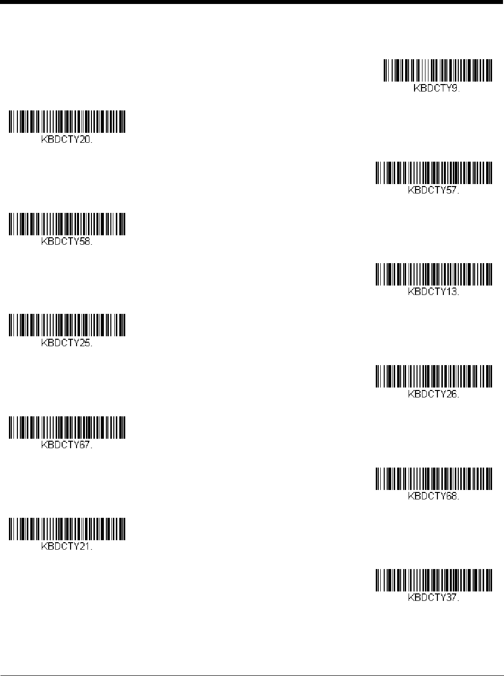
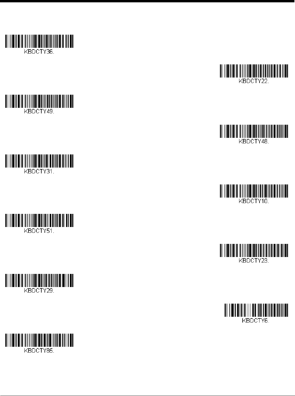
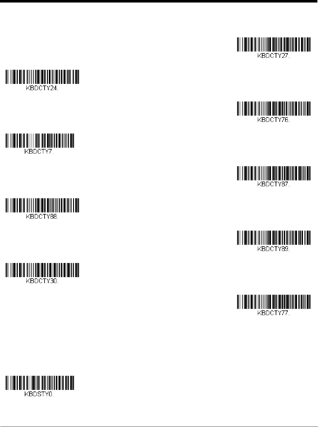
Keyboard Country Layout ....................................................................................................2-7
Keyboard Style...................................................................................................................2-14
Keyboard Conversion ........................................................................................................2-15
Control Character Output...................................................................................................2-16
Keyboard Modifiers ............................................................................................................2-16
Table of Contents
Preliminary draft_1

ii
RS232 Modifiers ................................................................................................................2-18
RS232 Baud Rate........................................................................................................2-18
RS232 Word Length: Data Bits, Stop Bits, and Parity................................................. 2-19
RS232 Receiver Time-Out...........................................................................................2-20
RS232 Handshaking.................................................................................................... 2-20
RS232 Timeout............................................................................................................2-20
XON/XOFF .................................................................................................................. 2-21
ACK/NAK..................................................................................................................... 2-21
Scanner to Bioptic Communication ................................................................................... 2-21
Scanner-Bioptic Packet Mode ..................................................................................... 2-21
Scanner-Bioptic ACK/NAK Mode................................................................................. 2-22
Scanner-Bioptic ACK/NAK Timeout............................................................................. 2-22
Chapter 3 - Cordless System Operation
How the Cordless Charge Base/Access Point Works .........................................................3-1
Linking the Scanner to a Charge Base................................................................................3-1
Linking the Scanner to an Access Point.............................................................................. 3-1
Replacing a Linked Scanner................................................................................................3-2
Communication Between the Cordless System
and the Host......................................................................................................................3-2
Programming the Scanner and Base or Access Point ........................................................ 3-3
RF (Radio Frequency) Module Operation ........................................................................... 3-3
System Conditions...............................................................................................................3-3
Linking Process ............................................................................................................. 3-3
Scanner Is Out of Range ............................................................................................... 3-3
Scanner Is Moved Back Into Range ..............................................................................3-3
Out of Range and Back into Range with Batch Mode On.............................................. 3-3
Page Button......................................................................................................................... 3-3
About the Battery................................................................................................................. 3-4
Charging Information ..................................................................................................... 3-4
Battery Recommendations ............................................................................................3-4
Proper Disposal of the Battery....................................................................................... 3-4
Beeper and LED Sequences and Meaning ......................................................................... 3-5
Scanner LED Sequences and Meaning.........................................................................3-5
Base/Access Point LED Sequences and Meaning........................................................3-5
Base Power Communication Indicator........................................................................... 3-5
Reset Scanner..................................................................................................................... 3-6
Scanning While in Base Cradle ...........................................................................................3-6
Base Charging Modes......................................................................................................... 3-6
Paging ................................................................................................................................. 3-7
Paging Mode..................................................................................................................3-7
Paging Pitch...................................................................................................................3-7
Error Indicators.................................................................................................................... 3-8
Beeper Pitch - Base Error.............................................................................................. 3-8
Number of Beeps - Base Error ...................................................................................... 3-8
Scanner Report ................................................................................................................... 3-8
Scanner Address.................................................................................................................3-9
Base or Access Point Address ............................................................................................ 3-9
Preliminary draft_1

iii
Scanner Modes ...................................................................................................................3-9
Charge Only Mode.........................................................................................................3-9
Linked Modes ................................................................................................................3-9
Unlinking the Scanner ....................................................................................................... 3-10
Override Locked Scanner............................................................................................3-10
Out-of-Range Alarm ..........................................................................................................3-10
Alarm Sound Type....................................................................................................... 3-11
Scanner Power Time-Out Timer........................................................................................ 3-11
Flexible Power Management............................................................................................. 3-12
Batch Mode ....................................................................................................................... 3-13
Batch Mode Beep ........................................................................................................ 3-14
Batch Mode Storage....................................................................................................3-14
Batch Mode Quantity ................................................................................................... 3-15
Batch Mode Output Order............................................................................................3-16
Total Records ..............................................................................................................3-17
Delete Last Code......................................................................................................... 3-17
Clear All Codes............................................................................................................3-17
Transmit Records to Host............................................................................................ 3-17
Batch Mode Transmit Delay ........................................................................................ 3-17
Multiple Scanner Operation ............................................................................................... 3-18
Scanner Name...................................................................................................................3-18
Application Work Groups................................................................................................... 3-19
Application Work Group Selection............................................................................... 3-20
Resetting the Factory Defaults: All Application Work Groups ........................................... 3-20
Resetting the Custom Defaults: All Application Work Groups ...........................................3-21
Using the Scanner with Bluetooth Devices........................................................................ 3-21
Bluetooth HID Keyboard Connect................................................................................3-21
Virtual Keyboard .......................................................................................................... 3-22
Bluetooth HID Keyboard Disconnect ...........................................................................3-23
Bluetooth Serial Port - PCs/Laptops............................................................................3-23
PDAs/Mobility Systems Devices.................................................................................. 3-23
Changing the Scanner’s Bluetooth PIN Code.............................................................. 3-23
Minimizing Bluetooth/ISM Band Network Activity.............................................................. 3-23
Auto Reconnect Mode ................................................................................................. 3-24
Maximum Link Attempts .............................................................................................. 3-24
Relink Time-Out........................................................................................................... 3-25
Bluetooth/ISM Network Activity Examples...................................................................3-25
Host Acknowledgment....................................................................................................... 3-26
Chapter 4 - Input/Output Settings
Power Up Beeper ................................................................................................................4-1
Beep on BEL Character....................................................................................................... 4-1
Trigger Click ........................................................................................................................ 4-2
Preliminary draft_1

iv
Good Read and Error Indicators.......................................................................................... 4-2
Beeper – Good Read..................................................................................................... 4-2
Beeper Volume – Good Read........................................................................................ 4-2
Beeper Pitch – Good Read............................................................................................ 4-3
Vibrate – Good Read..................................................................................................... 4-3
Beeper Pitch – Error ...................................................................................................... 4-4
Beeper Duration – Good Read ...................................................................................... 4-4
LED – Good Read ......................................................................................................... 4-4
Number of Beeps – Good Read .................................................................................... 4-5
Number of Beeps – Error............................................................................................... 4-5
Beeper Volume Max ...................................................................................................... 4-5
Good Read Delay .......................................................................................................... 4-5
User-Specified Good Read Delay..................................................................................4-6
Manual Trigger Modes.........................................................................................................4-6
LED Illumination - Manual Trigger ................................................................................. 4-6
Serial Trigger Mode.............................................................................................................4-7
Read Time-Out .............................................................................................................. 4-7
Presentation Mode .............................................................................................................. 4-7
LED Illumination - Presentation Mode ........................................................................... 4-8
Presentation LED Behavior after Decode......................................................................4-8
Presentation Sensitivity ................................................................................................. 4-8
Presentation Centering.................................................................................................. 4-8
In-Stand Sensor Mode.......................................................................................................4-10
CodeGate®........................................................................................................................ 4-10
Streaming Presentation™ Mode ....................................................................................... 4-11
Streaming Presentation In-Stand Programming..........................................................4-11
Mobile Phone Read Mode.................................................................................................4-11
Hands Free Time-Out........................................................................................................ 4-12
Reread Delay..................................................................................................................... 4-12
User-Specified Reread Delay ......................................................................................4-12
2D Reread Delay ......................................................................................................... 4-13
Character Activation Mode ................................................................................................ 4-13
Activation Character .................................................................................................... 4-14
End Character Activation After Good Read.................................................................4-14
Character Activation Timeout ......................................................................................4-14
Character Deactivation Mode ............................................................................................ 4-14
Deactivation Character ................................................................................................ 4-15
Illumination Lights.............................................................................................................. 4-15
Aimer Delay ....................................................................................................................... 4-15
User-Specified Aimer Delay......................................................................................... 4-16
Aimer Mode ....................................................................................................................... 4-16
Centering........................................................................................................................... 4-16
Preferred Symbology......................................................................................................... 4-18
High Priority Symbology .............................................................................................. 4-18
Low Priority Symbology ............................................................................................... 4-18
Preferred Symbology Time-out.................................................................................... 4-19
Preferred Symbology Default.......................................................................................4-19
Preliminary draft_1

v
Output Sequence Overview............................................................................................... 4-19
Output Sequence Editor ..............................................................................................4-19
To Add an Output Sequence ....................................................................................... 4-19
Other Programming Selections.................................................................................... 4-20
Output Sequence Editor ..............................................................................................4-21
Partial Sequence .........................................................................................................4-21
Require Output Sequence ........................................................................................... 4-21
Multiple Symbols ............................................................................................................... 4-22
No Read ............................................................................................................................ 4-22
Video Reverse ...................................................................................................................4-23
Working Orientation........................................................................................................... 4-23
Chapter 5 - Data Editing
Prefix/Suffix Overview ......................................................................................................... 5-1
To Add a Prefix or Suffix:............................................................................................... 5-1
To Clear One or All Prefixes or Suffixes........................................................................5-2
To Add a Carriage Return Suffix to All Symbologies.....................................................5-2
Prefix Selections.................................................................................................................. 5-2
Suffix Selections.................................................................................................................. 5-2
Function Code Transmit ......................................................................................................5-3
Intercharacter, Interfunction, and Intermessage Delays......................................................5-3
Intercharacter Delay ......................................................................................................5-3
User Specified Intercharacter Delay..............................................................................5-3
Interfunction Delay.........................................................................................................5-4
Intermessage Delay.......................................................................................................5-4
Chapter 6 - Data Formatting
Data Format Editor Introduction .......................................................................................... 6-1
Add a Data Format .............................................................................................................. 6-1
Other Programming Selections...................................................................................... 6-2
Terminal ID Table................................................................................................................ 6-3
Data Format Editor Commands........................................................................................... 6-3
Move Commands...........................................................................................................6-6
Search Commands........................................................................................................ 6-7
Miscellaneous Commands............................................................................................. 6-9
Data Formatter ..................................................................................................................6-12
Data Format Non-Match Error Tone............................................................................ 6-13
Primary/Alternate Data Formats........................................................................................6-13
Single Scan Data Format Change............................................................................... 6-13
Chapter 7 - Symbologies
All Symbologies................................................................................................................... 7-1
Message Length Description...............................................................................................7-1
Codabar............................................................................................................................... 7-2
Codabar Concatenation.................................................................................................7-3
Preliminary draft_1

vi
Code 39 ............................................................................................................................... 7-4
Code 32 Pharmaceutical (PARAF)................................................................................ 7-5
Full ASCII....................................................................................................................... 7-6
Code 39 Code Page ...................................................................................................... 7-6
Interleaved 2 of 5................................................................................................................. 7-7
NEC 2 of 5........................................................................................................................... 7-8
Code 93 ............................................................................................................................... 7-9
Code 93 Code Page .................................................................................................... 7-10
Straight 2 of 5 Industrial (three-bar start/stop)................................................................... 7-11
Straight 2 of 5 IATA (two-bar start/stop)............................................................................7-12
Matrix 2 of 5....................................................................................................................... 7-13
Code 11 ............................................................................................................................. 7-14
Code 128........................................................................................................................... 7-15
ISBT 128 Concatenation..............................................................................................7-15
Code 128 Code Page .................................................................................................. 7-16
GS1-128 ............................................................................................................................ 7-17
Telepen.............................................................................................................................. 7-18
UPC-A ............................................................................................................................... 7-19
UPC-A/EAN-13 with Extended Coupon Code...................................................................7-21
Coupon GS1 DataBar Output............................................................................................ 7-21
UPC-E0 ............................................................................................................................. 7-22
UPC-E1 ............................................................................................................................. 7-24
EAN/JAN-13 ......................................................................................................................7-24
Convert UPC-A to EAN-13 .......................................................................................... 7-24
ISBN Translate ............................................................................................................ 7-26
EAN/JAN-8 ........................................................................................................................ 7-27
MSI .................................................................................................................................... 7-29
GS1 DataBar Omnidirectional ........................................................................................... 7-31
GS1 DataBar Limited.........................................................................................................7-31
GS1 DataBar Expanded.................................................................................................... 7-32
Trioptic Code ..................................................................................................................... 7-32
Codablock A ...................................................................................................................... 7-33
Codablock F ...................................................................................................................... 7-34
PDF417 ............................................................................................................................. 7-35
MacroPDF417 ................................................................................................................... 7-35
MicroPDF417.....................................................................................................................7-36
GS1 Composite Codes...................................................................................................... 7-36
UPC/EAN Version........................................................................................................7-37
GS1 Emulation ..................................................................................................................7-37
TCIF Linked Code 39 (TLC39) .......................................................................................... 7-38
QR Code............................................................................................................................ 7-38
QR Code Page ............................................................................................................7-39
Data Matrix ........................................................................................................................ 7-40
Data Matrix Code Page ............................................................................................... 7-40
MaxiCode .......................................................................................................................... 7-41
Aztec Code ........................................................................................................................ 7-42
Aztec Code Page......................................................................................................... 7-42
Chinese Sensible (Han Xin) Code.....................................................................................7-43
Preliminary draft_1

vii
Postal Codes - 2D .............................................................................................................7-44
Single 2D Postal Codes:.............................................................................................. 7-44
Combination 2D Postal Codes:....................................................................................7-45
Postal Codes - Linear........................................................................................................7-48
China Post (Hong Kong 2 of 5).................................................................................... 7-48
Korea Post...................................................................................................................7-49
Chapter 8 - Imaging Commands
Single-Use Basis ................................................................................................................. 8-1
Command Syntax................................................................................................................ 8-1
Image Snap - IMGSNP........................................................................................................ 8-1
IMGSNP Modifiers......................................................................................................... 8-1
Image Ship - IMGSHP .........................................................................................................8-3
IMGSHP Modifiers......................................................................................................... 8-4
Intelligent Signature Capture - IMGBOX ...........................................................................8-10
Signature Capture Optimize ........................................................................................ 8-10
IMGBOX Modifiers....................................................................................................... 8-11
RF Default Imaging Device................................................................................................ 8-14
Chapter 9 - Interface Keys
Keyboard Function Relationships........................................................................................ 9-1
Supported Interface Keys ....................................................................................................9-3
Chapter 10 - Utilities
To Add a Test Code I.D. Prefix to All Symbologies........................................................... 10-1
Show Decoder Revision .................................................................................................... 10-1
Show Scan Driver Revision ...............................................................................................10-1
Show Software Revision.................................................................................................... 10-1
Show Data Format............................................................................................................. 10-1
Test Menu.......................................................................................................................... 10-2
TotalFreedom ....................................................................................................................10-2
Application Plug-Ins (Apps) ............................................................................................... 10-2
EZConfig-Scanning Introduction........................................................................................ 10-3
Installing EZConfig-Scanning from the Web................................................................ 10-3
Resetting the Factory Defaults .......................................................................................... 10-4
Chapter 11 - Serial Programming Commands
Conventions....................................................................................................................... 11-1
Menu Command Syntax.................................................................................................... 11-1
Query Commands ............................................................................................................. 11-1
Responses................................................................................................................... 11-2
Trigger Commands............................................................................................................11-3
Resetting the Custom Defaults.......................................................................................... 11-3
Menu Commands ..............................................................................................................11-4
Chapter 12 - Product Specifications
Preliminary draft_1

viii
Xenon 1900/1910 Corded Scanner Product Specifications .............................................. 12-1
Xenon 1902/1912 Cordless Scanner Product Specifications ............................................12-1
Granit 1910i Industrial Corded Scanner Product Specifications........................................ 12-2
Granit 1911i Industrial Cordless Scanner Product Specifications .....................................12-3
Granit 1980i Industrial Full Range Corded Scanner Product Specifications .....................12-4
Granit 1981i Industrial Full Range Cordless Scanner Product Specifications................... 12-5
CCB01-010BT Charge Base Product Specifications......................................................... 12-6
CCB02-100BT Industrial Charge Base Product Specifications ......................................... 12-6
Depth of Field Charts......................................................................................................... 12-8
Xenon B&W Scanner Typical Performance................................................................. 12-8
Xenon B&W Scanner Guaranteed Performance ......................................................... 12-8
Xenon Color Scanner (Model COL) Typical Performance........................................... 12-9
Xenon Color Scanner (Model COL) Guaranteed Performance .................................. 12-9
Granit 1910i/1911i Scanner Typical Performance .................................................... 12-10
Granit 1910i/1911i Scanner Guaranteed Performance ............................................ 12-10
Granit 1980i/1981i Scanner Typical Performance .................................................... 12-11
Granit 1980i/1981i Scanner Guaranteed Performance ............................................ 12-11
Standard Connector Pinouts ...........................................................................................12-12
Keyboard Wedge....................................................................................................... 12-12
Serial Output.............................................................................................................. 12-12
RS485 Output............................................................................................................ 12-12
USB ........................................................................................................................... 12-13
Required Safety Labels ...................................................................................................12-13
Chapter 13 - Maintenance
Repairs .............................................................................................................................. 13-1
Maintenance ...................................................................................................................... 13-1
Cleaning the Scanner .................................................................................................. 13-1
Cleaning the Window...................................................................................................13-1
Health Care Housing ................................................................................................... 13-1
Inspecting Cords and Connectors ............................................................................... 13-2
Replacing Cables in Corded Scanners.............................................................................. 13-2
Replacing a Xenon Interface Cable............................................................................. 13-2
Replacing a Granit Interface Cable.............................................................................. 13-2
Replacing Cables and Batteries in Cordless Systems ...................................................... 13-2
Replacing an Interface Cable in a Base ...................................................................... 13-2
Changing a Xenon Scanner Battery ............................................................................ 13-3
Changing a Granit Scanner Battery.............................................................................13-3
Troubleshooting a Corded Scanner................................................................................... 13-3
Troubleshooting a Cordless System.................................................................................. 13-4
Troubleshooting a Base...............................................................................................13-4
Troubleshooting a Cordless Scanner .......................................................................... 13-4
Chapter 14 - Customer Support
Technical Assistance.........................................................................................................14-1
Product Service and Repair............................................................................................... 14-1
Preliminary draft_1

ix
Appendix A - Reference Charts
Symbology Charts ...............................................................................................................A-1
Linear Symbologies .......................................................................................................A-1
2D Symbologies.............................................................................................................A-2
Postal Symbologies .......................................................................................................A-2
ASCII Conversion Chart (Code Page 1252)........................................................................A-3
Lower ASCII Reference Table.............................................................................................A-4
ISO 2022/ISO 646 Character Replacements ......................................................................A-7
Unicode Key Maps ............................................................................................................A-10
Sample Symbols
Programming Chart
Preliminary draft_1

x
Preliminary draft_1

1 - 1
1
Getting Started
About This Manual
This User’s Guide provides installation and programming instructions for the Xenon™ 1900 and 1910 corded area-imaging
scanners, the Xenon 1902 and 1912 cordless area-imaging scanners, the Granit 1910i and 1980i corded industrial scanners,
and the Granit 1911i and 1981i cordless industrial scanners. Product specifications, dimensions, warranty, and customer sup-
port information are also included.
Honeywell bar code scanners are factory programmed for the most common terminal and communications settings. If you need
to change these settings, programming is accomplished by scanning the bar codes in this guide.
An asterisk (*) next to an option indicates the default setting.
Unpacking Your Device
After you open the shipping carton containing the product, take the following steps:
• Check for damage during shipment. Report damage immediately to the carrier who delivered the carton.
• Make sure the items in the carton match your order.
• Save the shipping container for later storage or shipping.
Connecting the Device
Connecting with USB
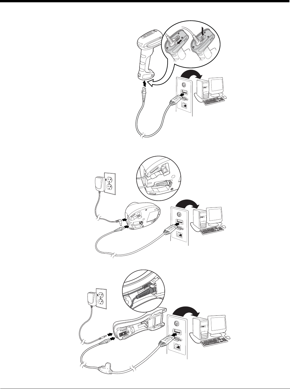
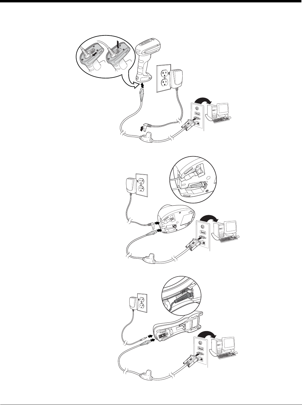
A scanner or a cordless base can be connected to the USB port of a computer.
1. Connect the appropriate interface cable to the device first, then to the computer.
Corded Xenon Scanner
USB Connection:
Preliminary draft_1
1 - 2
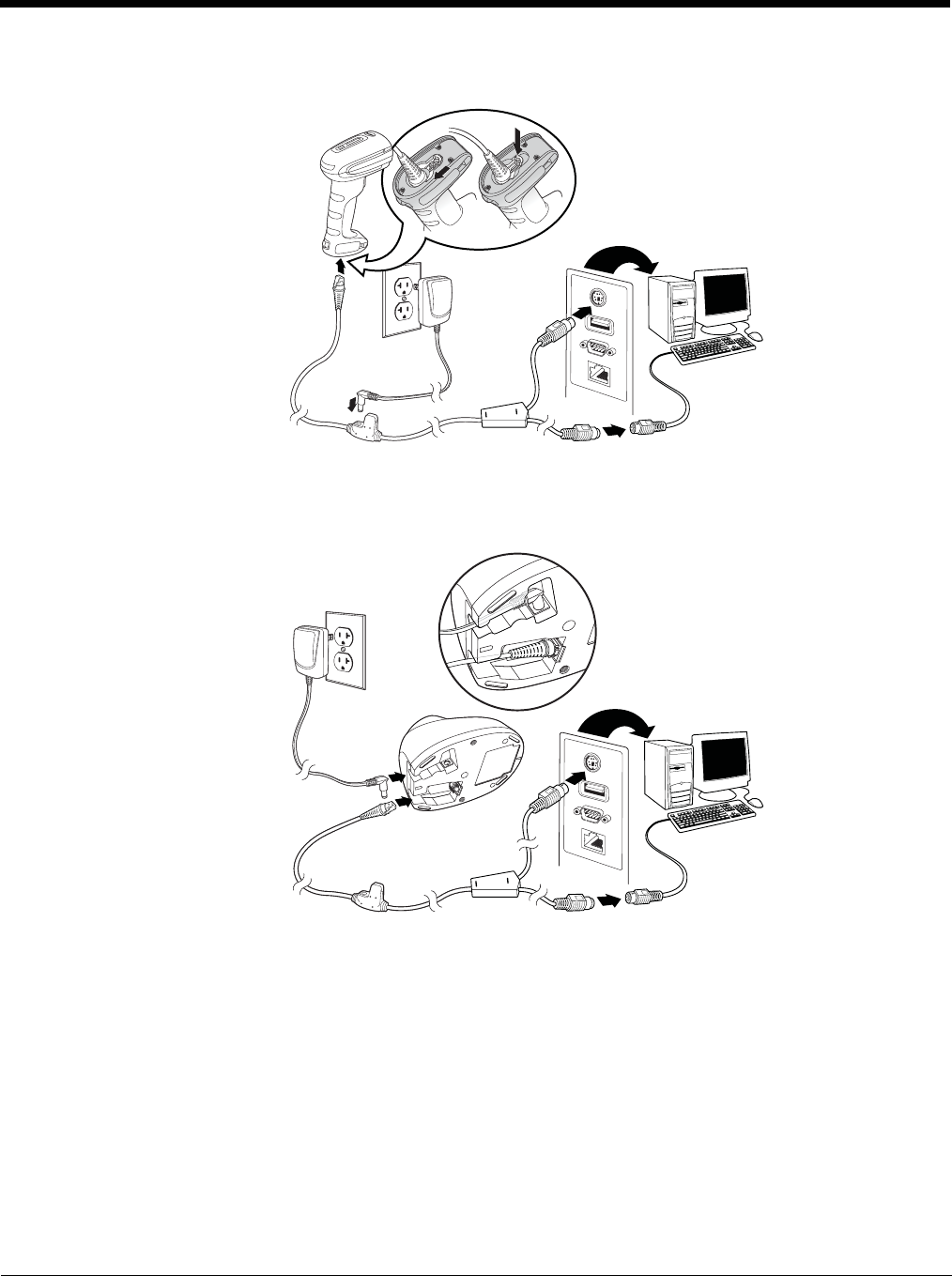
2. If you are connecting a Granit scanner, make sure the cable is pushed tightly into the scanner. Loosen the locking plate
and slide it over the base of the cable connector to lock the cable in place. Tighten the screw.
Note: The power supply must be ordered separately, if needed.
Corded Granit Scanner
USB Connection:
CCB01-010BT Base
USB Connection:
CCB02-100BT Base
USB Connection:
Preliminary draft_1
1 - 3
3. If you are connecting a CCB01-010BT Base, make sure the cables are secured in the wireways in the bottom of the
cordless base and the base sits flat on a horizontal surface. If you are connecting a CCB02-100BT Base, see Mounting
a CCB02-100BT Base on page 1-8.
4. The scanner beeps.
5. Verify the scanner or cordless base operation by scanning a bar code from the Sample Symbols in the back of this
manual.
The unit defaults to a USB PC Keyboard. Refer to page 2-3 for other USB terminal settings.
For additional USB programming and technical information, refer to “USB Application Note,” available at www.honey-
wellaidc.com.
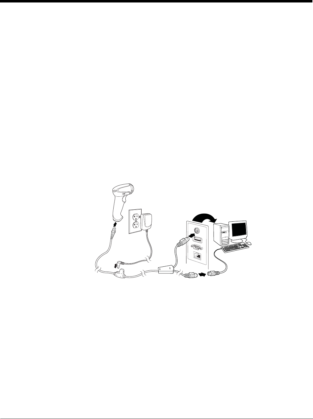
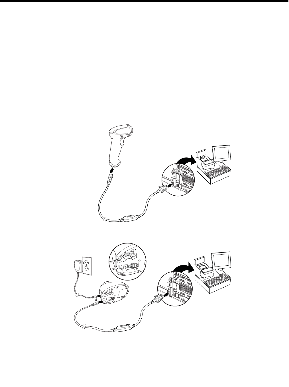
Connecting with Keyboard Wedge
A scanner or cordless base can be connected between the keyboard and PC as a “keyboard wedge,” where the scanner
provides data output that is similar to keyboard entries.
Note: The Granit 1980i does not support the keyboard wedge interface.
The following is an example of a keyboard wedge connection:
1. Turn off power and disconnect the keyboard cable from the back of the terminal/computer.
2. Connect the appropriate interface cable to the device and to the terminal/computer.
Corded Xenon Scanner
Keyboard Wedge
Connection:
Preliminary draft_1
1 - 4
3. If you are connecting a Granit scanner, make sure the cable is pushed tightly into the scanner. Loosen the locking plate
and slide it over the base of the cable connector to lock the cable in place. Tighten the screw.
Corded Granit Scanner
Keyboard Wedge
Connection:
CCB01-010BT Base Keyboard
Wedge Connection:
Preliminary draft_1
1 - 5
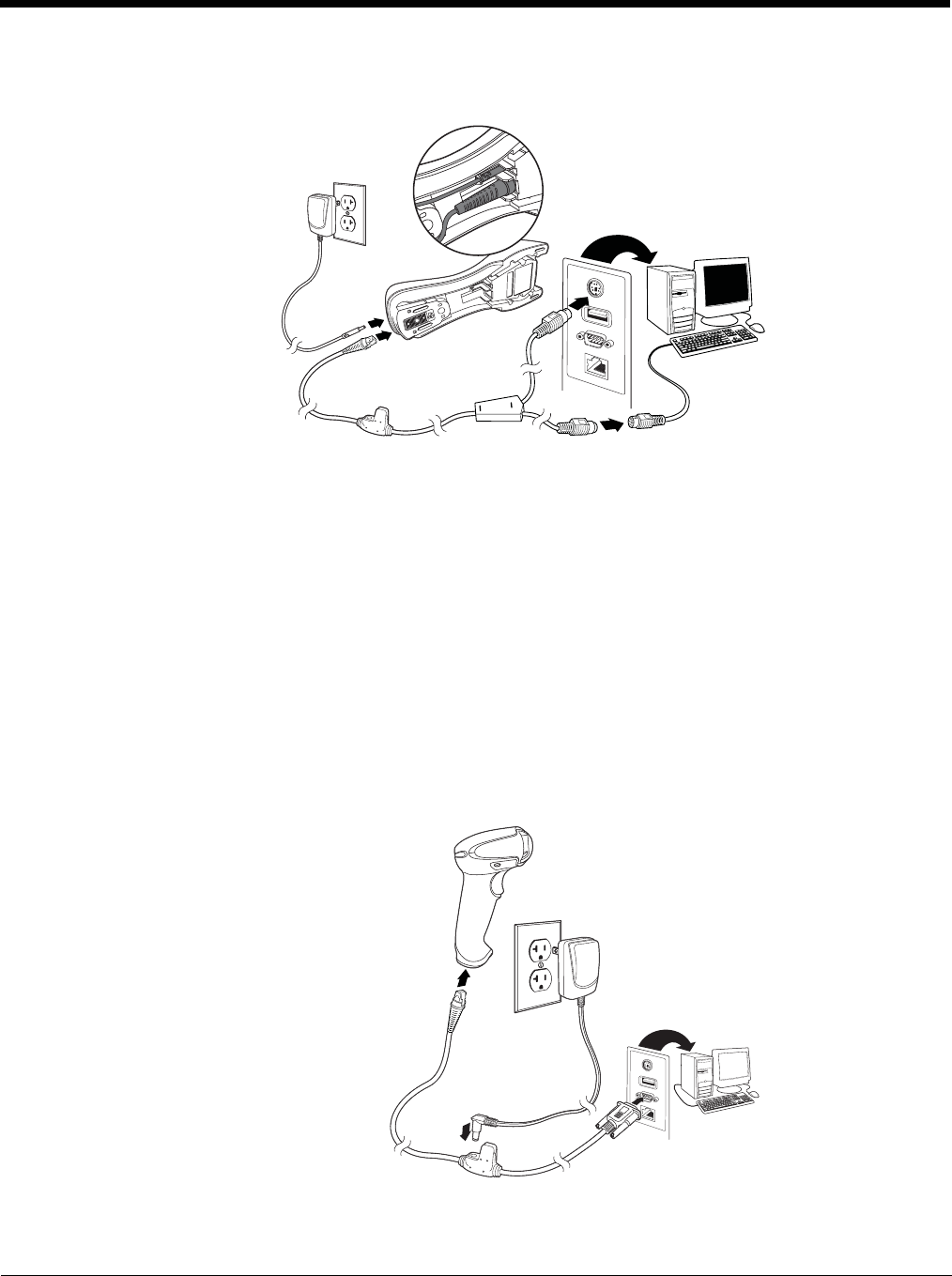
Note: The power supply must be ordered separately, if needed.
4. If you are connecting a CCB01-010BT Base, make sure the cables are secured in the wireways in the bottom of the
cordless base and the base sits flat on a horizontal surface. If you are connecting a CCB02-100BT Base, see Mounting
a CCB02-100BT Base on page 1-8.
5. Turn the terminal/computer power back on. The scanner beeps.
6. Verify the scanner or cordless base operation by scanning a bar code from the Sample Symbols in the back of this
manual. The scanner beeps once. If using a Granit scanner, it also vibrates.
The unit defaults to an IBM PC AT and compatibles keyboard wedge interface with a USA keyboard. A carriage return (CR)
suffix is added to bar code data.
Connecting with RS232 Serial Port
1. Turn off power to the terminal/computer.
2. Connect the appropriate interface cable to the scanner.
Note: For the scanner or cordless base to work properly, you must have the correct cable for your type of terminal/computer.
CCB02-100BT Base Keyboard
Wedge Connection:
Corded Xenon Scanner
RS232 Serial Port
Connection:
Preliminary draft_1
1 - 6
3. If you are connecting a Granit scanner, make sure the cable is pushed tightly into the scanner. Loosen the locking plate
and slide it over the base of the cable connector to lock the cable in place. Tighten the screw.
Note: The power supply must be ordered separately, if needed.
Corded Granit Scanner RS232 Serial
Port Connection:
CCB01-010BT Base
RS232 Serial Port Connection:
CCB02-100BT Base
RS232 Serial Port Connection:
Preliminary draft_1
1 - 7
4. If you are connecting a CCB01-010BT Base, make sure the cables are secured in the wireways in the bottom of the
cordless base and the base sits flat on a horizontal surface. If you are connecting a CCB02-100BT Base, see Mounting
a CCB02-100BT Base on page 1-8.
5. Plug the serial connector into the serial port on your computer. Tighten the two screws to secure the connector to the
port.
6. Once the scanner or cordless base has been fully connected, power up the computer.
This interface programs 115,200 baud, 8 data bits, no parity, and 1 stop bit.
Connecting with RS485
A Xenon scanner or cordless base can be connected for an IBM POS terminal interface. (This interface is not available in
the Granit devices.)
1. Connect the appropriate interface cable to the device, then to the computer.
Note: The power supply must be ordered separately, if needed.
2. Make sure the cables are secured in the wireways in the bottom of the cordless base and the base sits flat on a
horizontal surface.
3. Turn the terminal/computer power back on. The scanner beeps.
Corded Xenon Scanner
RS485 Connection:
CCB01-010BT Base
RS485 Connection:
Preliminary draft_1
1 - 8
4. Verify the scanner or cordless base operation by scanning a bar code from the Sample Symbols in the back of this
manual. The scanner beeps once. If using a Granit scanner, it also vibrates.
For further RS485 settings, refer to RS485, page 2-2.
Mounting a CCB01-010BT Charge Base
Mounting a CCB02-100BT Base
The CCB02-100BT Base can be mounted on either a horizontal or vertical surface. The cables can be routed through either the
top or the bottom of the base.
The cables can be routed down through the bottom of the base, securing the cables in the wireways.
The cables can also be routed up through the top of the base, crossing them over and securing the cables in the wireways.
When routing the cables up through the top of the base, be sure to cross the cables over before placing in the wireways. If not,
too much strain is placed on the cable connectors.
8x32 thread
x .39 in. (10mm) deep
2.36 in.
59.84mm
3.35 in.
85.09mm
2.8 in.
72.1mm
Preliminary draft_1
1 - 9
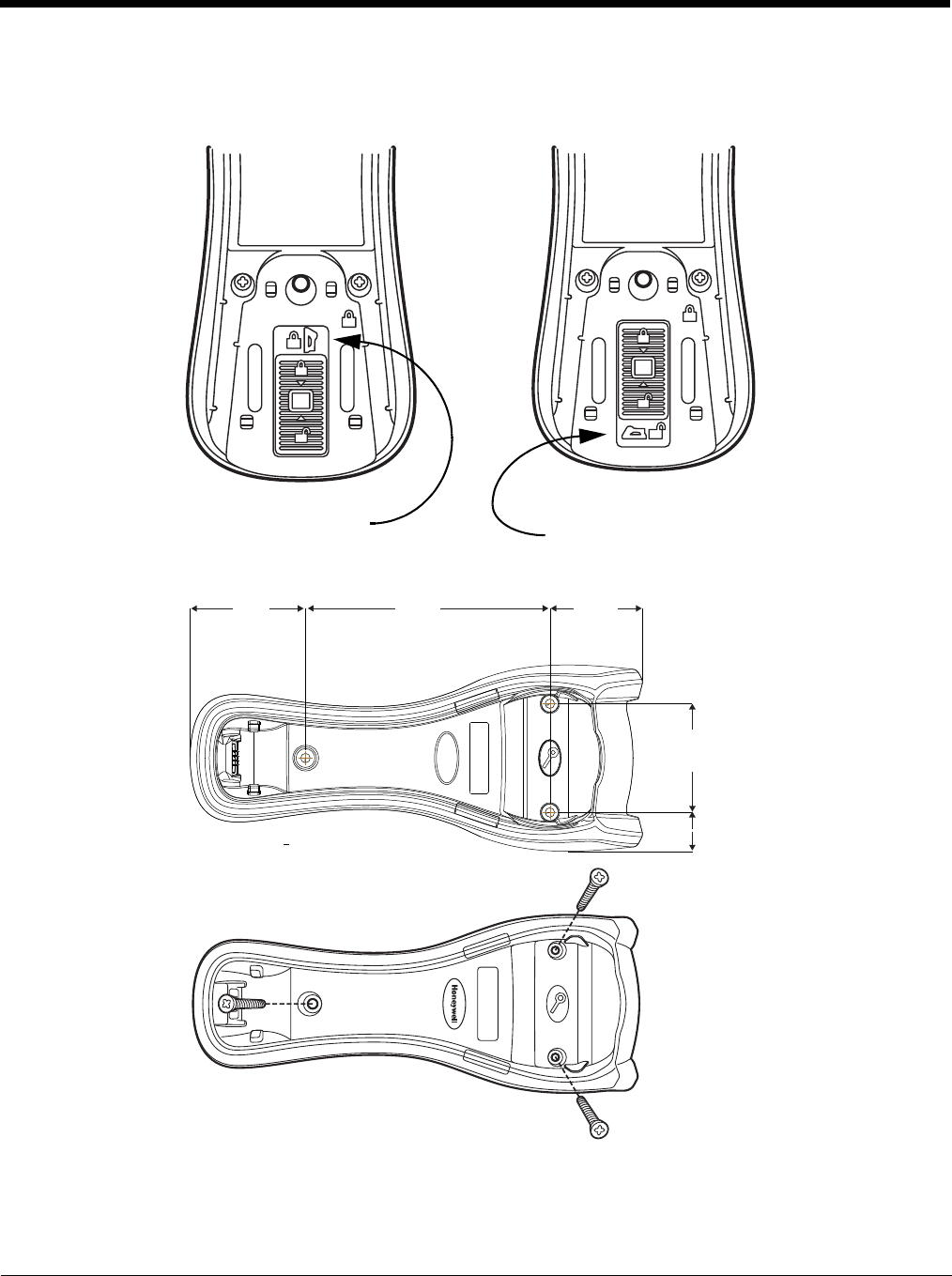
When mounted on a vertical surface, a locking system is used to secure the scanner when it is in the stand. When mounted on
a horizontal surface, the locking mechanism should be set to unlocked (pushed up). When mounted on a vertical surface, the
locking mechanism should be set to locked (pushed down).
Use 30mm screws, appropriate for the mounting surface material, to mount the base securely.
Locked position
for vertical mount
Unlocked position
for horizontal mount
2 in.
51.17mm
5.31 in.
134.92mm
2.51 in.
63.7mm
2.36 in.
60mm
.84 in.
21.42mm
Preliminary draft_1
1 - 10
Reading Techniques
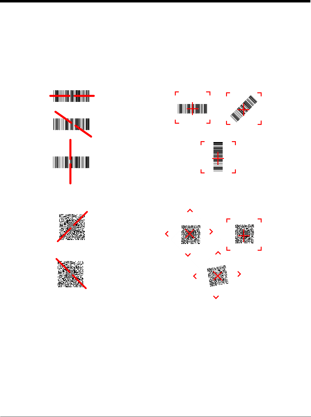
Xenon 1900/1902/1910/1912 and Granit 1910i/1911i
The Xenon 1900/1902 scanners have a view finder that projects a bright red aiming beam that corresponds to the scan-
ner’s horizontal field of view. The Xenon 1910/1912 and Granit 1910i/1911i scanners have an aiming pattern. The aiming
beam or pattern should be centered over the bar code, but it can be positioned in any direction for a good read.
The aiming beam or pattern is smaller when the scanner is closer to the code and larger when it is farther from the code.
Symbologies with smaller bars or elements (mil size) should be read closer to the unit. Symbologies with larger bars or ele-
ments (mil size) should be read farther from the unit. To read single or multiple symbols (on a page or on an object), hold
the scanner at an appropriate distance from the target, pull the trigger, and center the aiming beam or pattern on the sym-
bol. If the code being scanned is highly reflective (e.g., laminated), it may be necessary to tilt the code up 15° to 18° to pre-
vent unwanted reflection.
Linear bar codes
with aiming beam
2D Matrix symbol
with aiming beam
Linear bar codes
with aiming pattern
2D Matrix symbol
with aiming pattern
Preliminary draft_1
1 - 11
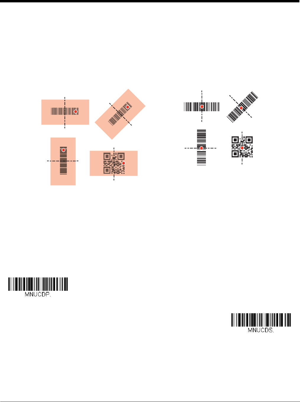
Granit 1980i/1981i
The Granit 1980i/1981i scanners have a laser aimer and the lighting from the red LEDs to use for aiming at a bar code.
These are used differently depending on if you are scanning at a near distance (< 11.8 inches / 30 cm) or far distance (up
to 50 feet / 15.2 meters). When scanning at a near distance use the red lighting and center the box over the bar code. The
laser aimer will be to the right of the center of the bar code. When scanning at a far distance use the laser aimer and aim at
the center of the bar code. When scanning at far distances you may not be able to see the red lighting. For both near dis-
tance and far distance scanning the red box and aimer can be positioned in any direction for a good read.
Menu Bar Code Security Settings
Honeywell scanners are programmed by scanning menu bar codes or by sending serial commands to the scanner. If you want
to restrict the ability to scan menu codes, you can use the Menu Bar Code Security settings. Please contact the nearest techni-
cal support office (see Technical Assistance on page 14-1) for further information.
Setting Custom Defaults
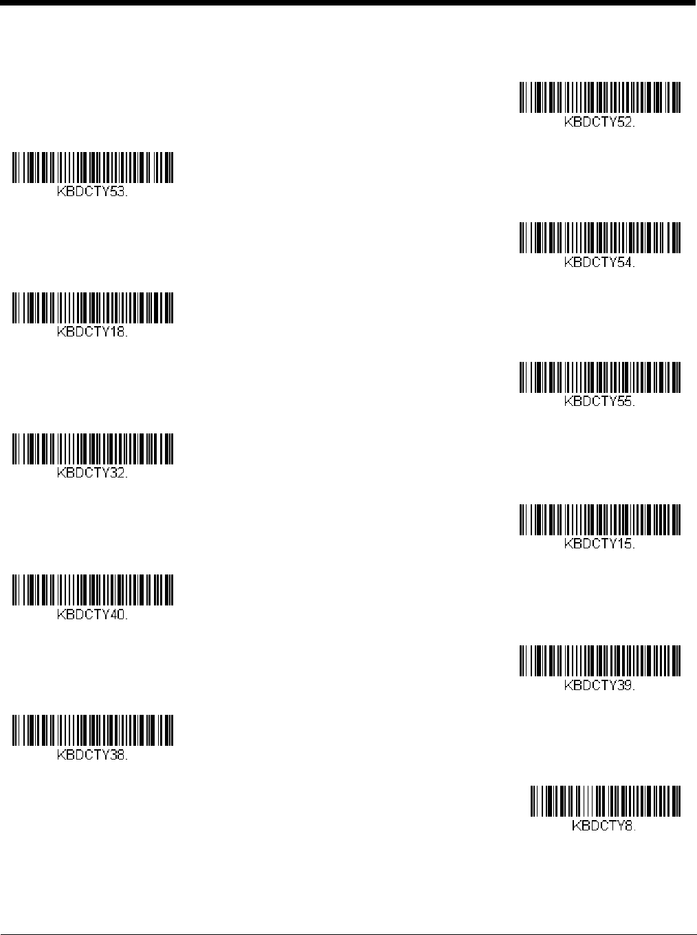
You have the ability to create a set of menu commands as your own, custom defaults. To do so, scan the Set Custom Defaults
bar code below before scanning the menu commands for your custom defaults. If a menu command requires scanning numeric
codes from the back cover, then a Save code, that entire sequence will be saved to your custom defaults. When you have
entered all the commands you want to save for your custom defaults, scan the Save Custom Defaults bar code.
Note: When using a cordless system, the Custom Defaults settings apply to all workgroups. Scanning the Save Defaults bar
code also causes both the scanner and the base or Access Point to perform a reset and become unlinked. The scanner
must be placed in its base to re-establish the link before any setup codes are entered. If using an Access Point, the linking
bar code must be scanned. See Cordless System Operation beginning on page 3-1 for additional information.
Near distance scanning
<11.8 in/30 cm Far distance scanning
up to 50 ft/15.2 m
Set Custom Defaults
Save Custom Defaults
Preliminary draft_1

1 - 12
You may have a series of custom settings and want to correct a single setting. To do so, just scan the new setting to overwrite
the old one. For example, if you had previously saved the setting for Beeper Volume at Low to your custom defaults, and decide
you want the beeper volume set to High, just scan the Set Custom Defaults bar code, then scan the Beeper Volume High
menu code, and then Save Custom Defaults. The rest of the custom defaults will remain, but the beeper volume setting will be
updated.
Resetting the Custom Defaults
If you want the custom default settings restored to your scanner, scan the Activate Custom Defaults bar code below. This is
the recommended default bar code for most users. It resets the scanner to the custom default settings. If there are no custom
defaults, it will reset the scanner to the factory default settings. Any settings that have not been specified through the custom
defaults will be defaulted to the factory default settings.
Note: If using a cordless system, scanning this bar code also causes both the scanner and the base or Access Point to perform
a reset and become unlinked. The scanner must be placed in its base to re-establish the link. If using an Access Point,
the linking bar code must be scanned. See Cordless System Operation beginning on page 3-1 for additional information.
Activate Custom Defaults
Preliminary draft_1

2 - 1
2
Programming the Interface
Introduction
This chapter describes how to program your system for the desired interface.
Programming the Interface - Plug and Play
Plug and Play bar codes provide instant scanner set up for commonly used interfaces.
Note: After you scan one of the codes, power cycle the host terminal to have the interface in effect.
Keyboard Wedge
If you want your system programmed for an IBM PC AT and compatibles keyboard wedge interface with a USA keyboard, scan
the bar code below. Keyboard wedge is the default interface.
Note: The Granit 1980i does not support the keyboard wedge interface.
Note: The following bar code also programs a carriage return (CR) suffix.
Laptop Direct Connect
For most laptops, scanning the Laptop Direct Connect bar code allows operation of the scanner in parallel with the integral
keyboard. The following Laptop Direct Connect bar code also programs a carriage return (CR) suffix and turns on Emulate
External Keyboard (page 2-15).
RS232 Serial Port
The RS232 Interface bar code is used when connecting to the serial port of a PC or terminal. The following RS232 Interface
bar code also programs a carriage return (CR) and a line feed (LF) suffix, baud rate, and data format as indicated below. It also
changes the trigger mode to manual.
Option Setting
Baud Rate 115,200 bps
Data Format 8 data bits, no parity bit, 1 stop bit
IBM PC AT and Compatibles with
CR suffix
Laptop Direct Connect
with CR suffix
RS232 Interface
Preliminary draft_1
2 - 2
RS485
Scan one of the following “Plug and Play” codes to program the scanner for an IBM POS terminal interface.
Note: This interface is not supported in Granit devices.
After scanning one of these codes, you must power cycle the cash register.
Each bar code above also programs the following suffixes for each symbology:
* Suffixes programmed for Code 128 with IBM 4683 Port 5B, IBM 4683 Port 9B HHBCR-1, and IBM 4683 Port 17 Interfaces
**Suffixes programmed for Code 128 with IBM 4683 Port 9 HHBCR-2 Interface
RS485 Packet Mode
The following selection allows you to break up large bar code data into smaller packets on an IBM POS terminal. To break
up large bar codes into small packets, scan the Packet Mode On bar code below. Scan the Packet Mode Off bar code if you
want large bar code data to be sent to the host in a single chunk. Default = Packet Mode Off.
Symbology Suffix Symbology Suffix
EAN 8 0C Code 39 00 0A 0B
EAN 13 16 Interleaved 2 of 5 00 0D 0B
UPC A 0D Code 128 * 00 0A 0B
UPC E 0A Code 128 ** 00 18 0B
MaxiCode 00 2F 0B
IBM Port 5B Interface
IBM Port 9B
HHBCR-1 Interface
IBM Port 17 Interface
IBM Port 9B
HHBCR-2 Interface
* Packet Mode Off
Packet Mode On
Preliminary draft_1
2 - 3
RS485 Packet Length
If you are using Packet mode, you can specify the size of the data “packet” that is sent to the host. Scan the Packet
Length bar code, then then the packet size (from 20 - 256) from the Programming Chart inside the back cover of this
manual, then Save. Default = 40.
USB IBM SurePos
Scan one of the following “Plug and Play” codes to program the scanner for an IBM SurePos (USB handheld scanner) or IBM
SurePos (USB tabletop scanner) interface.
Note: After scanning one of these codes, you must power cycle the cash register.
Each bar code above also programs the following suffixes for each symbology:
USB PC or Macintosh Keyboard
Scan one of the following codes to program the scanner for USB PC Keyboard or USB Macintosh Keyboard. Scanning these
codes also adds a CR suffix.
Symbology Suffix Symbology Suffix
EAN 8 0C Code 39 00 0A 0B
EAN 13 16 Interleaved 2 of 5 00 0D 0B
UPC A 0D Code 128 00 18 0B
UPC E 0A Code 39 00 0A 0B
Packet Length
USB IBM SurePos
(USB Handheld Scanner)
Interface
USB IBM SurePos
(USB Tabletop Scanner)
Interface
USB Keyboard (PC)
USB Keyboard (Mac)
USB Japanese Keyboard (PC)
Preliminary draft_1
2 - 4
USB HID
Scan the following code to program the scanner for USB HID bar code scanners.
USB Serial
Scan the following code to program the scanner to emulate a regular RS232-based COM Port. If you are using a Microsoft®
Windows® PC, you will need to download a driver from the Honeywell website (www.honeywellaidc.com). The driver will use
the next available COM Port number. Apple® Macintosh computers recognize the scanner as a USB CDC class device and
automatically use a class driver.
Note: No extra configuration (e.g., baud rate) is necessary.
CTS/RTS Emulation
ACK/NAK Mode
Remote MasterMind™ for USB
When using a USB interface, you may wish to configure your scanner to communicate with Remote MasterMind Scanner Man-
agement Software (ReM). Scan the ReM On bar code to communicate with ReM. To disable this capability, scan ReM Off.
USB HID Bar Code Scanner
USB Serial
CTS/RTS Emulation On
* CTS/RTS Emulation Off
ACK/NAK Mode On
* ACK/NAK Mode Off
ReM Off
Preliminary draft_1
2 - 5
Verifone® Ruby Terminal Default Settings
Scan the following Plug and Play code to program the scanner for a Verifone Ruby terminal. This bar code sets the baud rate to
1200 bps and the data format to 8 data bits, no parity bit, 1 stop bit. It also adds a line feed (LF) suffix and programs the follow-
ing prefixes for each symbology:
Gilbarco® Terminal Default Settings
Scan the following Plug and Play code to program the scanner for a Gilbarco terminal. This bar code sets the baud rate to 2400
bps and the data format to 7 data bits, even parity, 2 stop bits. It also adds a carriage return (CR) suffix and programs the follow-
ing prefixes for each symbology:
Honeywell Bioptic Aux Port Configuration
Scan the following Plug and Play code to program the scanner for a Honeywell bioptic scanner auxiliary port configuration. This
bar code sets the baud rate to 38400 bps and the data format to 8 data bits, no parity, 1 stop bit.
Symbology Prefix
UPC-A A
UPC-E A
EAN-8 FF
EAN-13 F
Symbology Prefix
UPC-A A
UPC-E E0
EAN-8 FF
EAN-13 F
ReM On
Verifone Ruby Settings
Gilbarco Settings
Honeywell Bioptic Settings
Preliminary draft_1
2 - 6
Datalogic™ Magellan® Aux Port Configuration
Scan the following Plug and Play code to program the scanner for a Datalogic Magellan auxiliary port configuration. This bar
code sets the baud rate to 9600 bps and the data format to 8 data bits, no parity, 1 stop bit.
NCR Bioptic Aux Port Configuration
Scan the following Plug and Play code to program the scanner for an NCR bioptic scanner auxiliary port configuration. The fol-
lowing prefixes are programmed for each symbology:
Wincor Nixdorf Terminal Default Settings
Scan the following Plug and Play code to program the scanner for a Wincor Nixdorf terminal. This bar code sets the baud rate
to 9600 bps and the data format to 8 data bits, no parity, 1 stop bit.
Wincor Nixdorf Beetle™ Terminal Default Settings
Scan the following Plug and Play code to program the scanner for a Wincor Nixdorf Beetle terminal. The following prefixes are
programmed for each symbology:
Symbology Prefix Symbology Prefix
UPC-A A Interleaved 2 of 5 b
UPC-E E0 Code 128 f
GS1 DataBar
Omnidirecitonal
r
EAN-8 FF GS1 DataBar
Expanded
r
EAN-13 F Codabar N
Code 39 a Code 32
Pharmaceutical
(PARAF)
a
Symbology Prefix Symbology Prefix
Code 128 K EAN-13 A
Code 93 L GS1-128 P
Codabar N Interleaved 2 of 5 I
UPC-A A0 Plessey O
UPC-E C Straight 2 of 5 IATA H
EAN-8 B All other bar codes M
Datalogic Magellan Settings
NCR Bioptic Settings
Wincor Nixdorf Terminal Settings
Preliminary draft_1
2 - 7
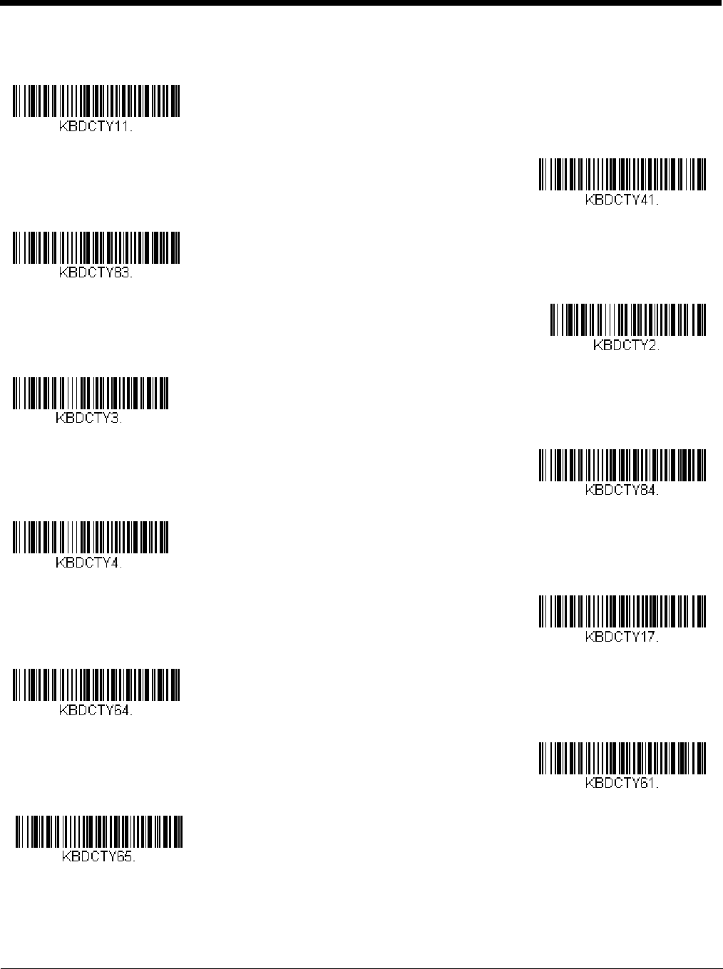
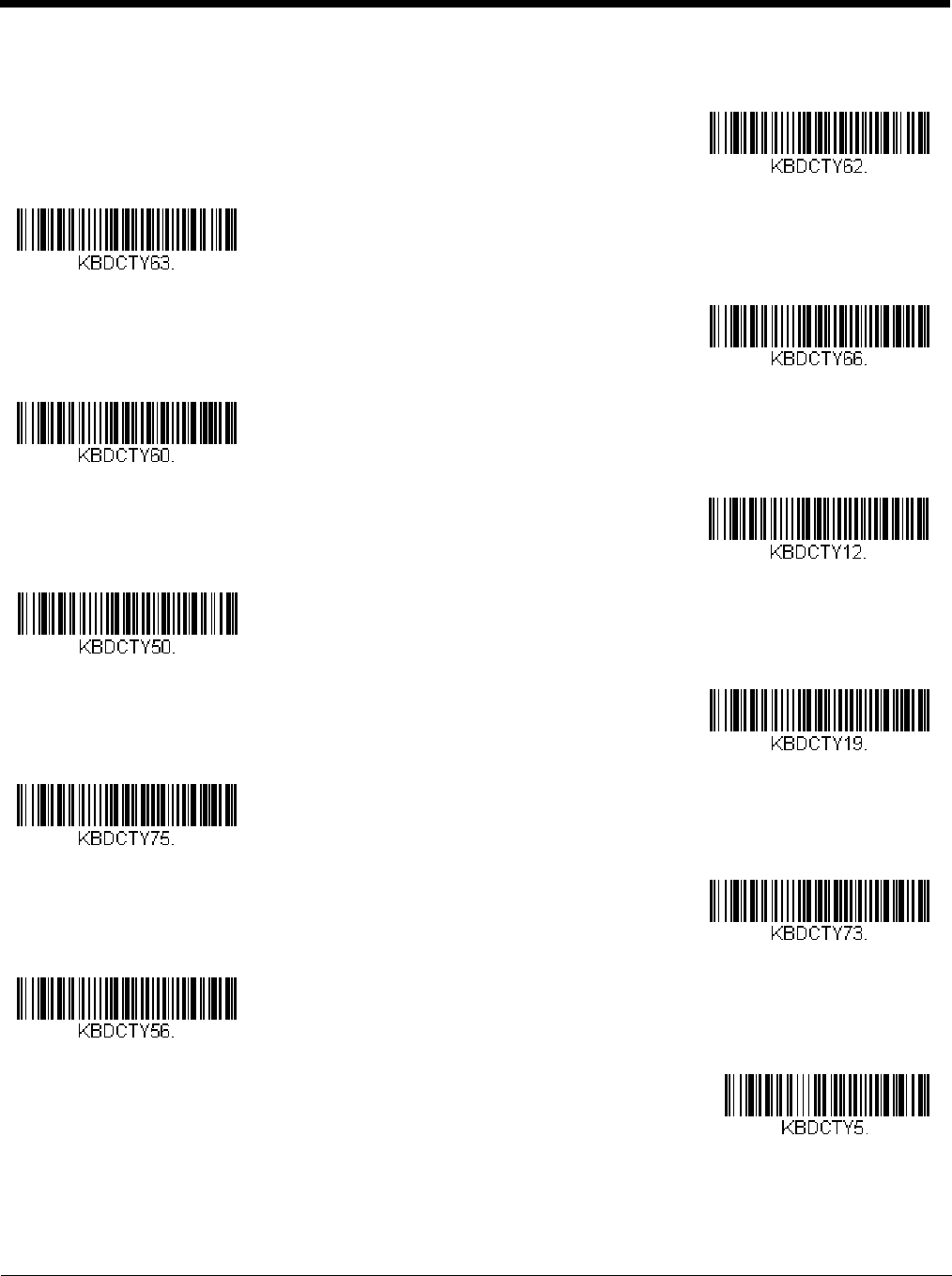
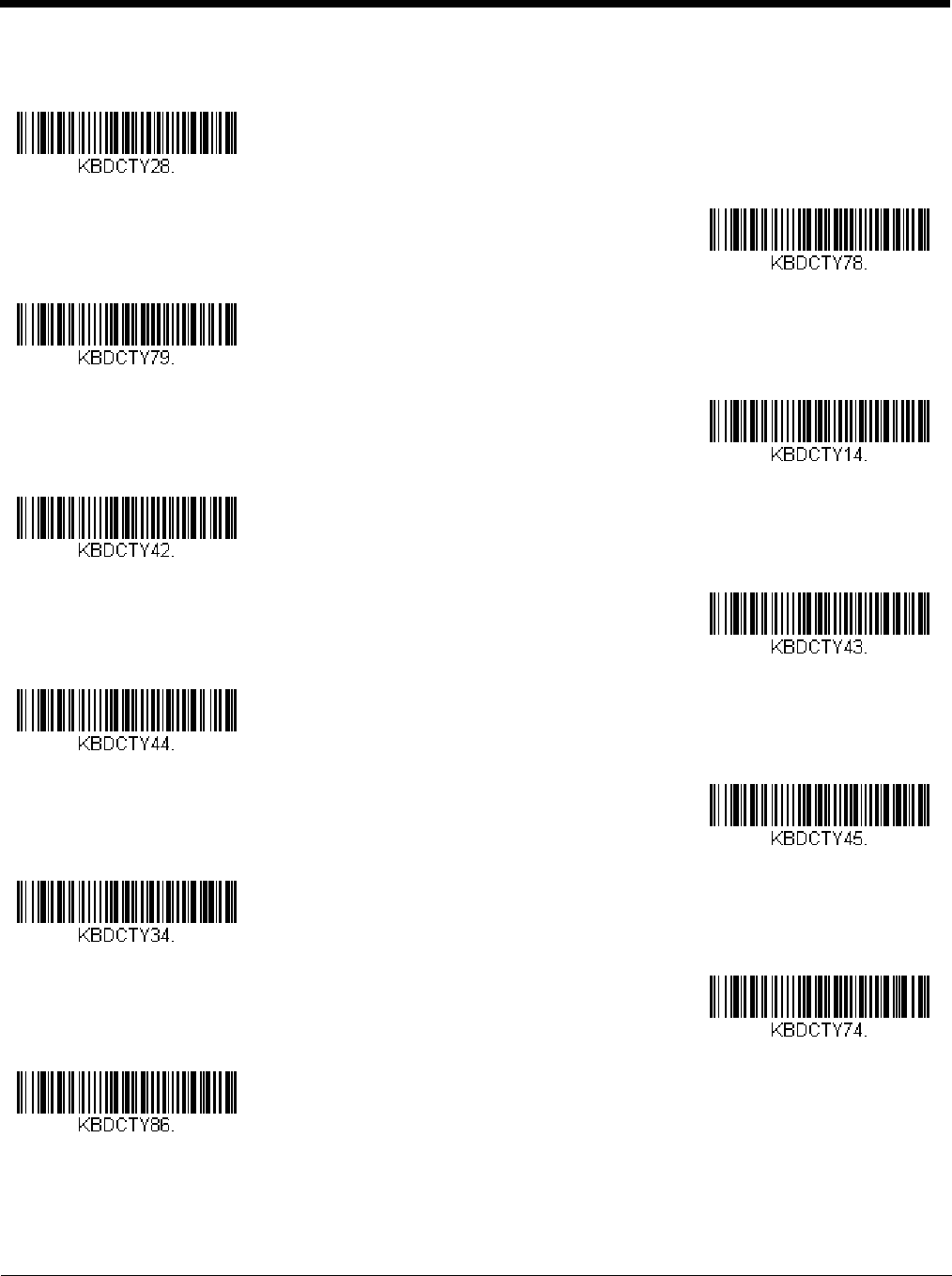
Keyboard Country Layout
Scan the appropriate country code below to program the keyboard layout for your country or language. As a general rule, the
following characters are supported, but need special care for countries other than the United States:
@ | $ # { } [ ] = / ‘ \ < > ~
Keyboard Countries
Wincor Nixdorf Beetle Settings
* United States
Albania
Azeri (Cyrillic)
Azeri (Latin)
Belarus
Belgium
Bosnia
Brazil
Brazil (MS)
Preliminary draft_1
2 - 8
Keyboard Countries (Continued)
Bulgaria (Cyrillic)
Bulgaria (Latin)
Canada (French legacy)
Canada (French)
Canada (Multilingual)
Croatia
Czech
Czech (Programmers)
Czech (QWERTY)
Czech (QWERTZ)
Denmark
Preliminary draft_1
2 - 9
Keyboard Countries (Continued)
Dutch (Netherlands)
Estonia
Faroese
Finland
France
Gaelic
Germany
Greek
Greek (220 Latin)
Greek (220)
Greek (319 Latin)
Preliminary draft_1
2 - 10
Keyboard Countries (Continued)
Greek (319)
Greek (Latin)
Greek (MS)
Greek (Polytonic)
Hebrew
Hungarian (101 key)
Hungary
Iceland
Irish
Italian (142)
Italy
Preliminary draft_1
2 - 11
Keyboard Countries (Continued)
Japan ASCII
Kazakh
Kyrgyz (Cyrillic)
Latin America
Latvia
Latvia (QWERTY)
Lithuania
Lithuania (IBM)
Macedonia
Malta
Mongolian (Cyrillic)
Preliminary draft_1
2 - 12
Keyboard Countries (Continued)
Norway
Poland
Polish (214)
Polish (Programmers)
Portugal
Romania
Russia
Russian (MS)
Russian (Typewriter)
SCS
Serbia (Cyrillic)
Preliminary draft_1
2 - 13
Keyboard Countries (Continued)
Serbia (Latin)
Slovakia
Slovakia (QWERTY)
Slovakia (QWERTZ)
Slovenia
Spain
Spanish variation
Sweden
Switzerland (French)
Switzerland (German)
Tatar
Preliminary draft_1
2 - 14
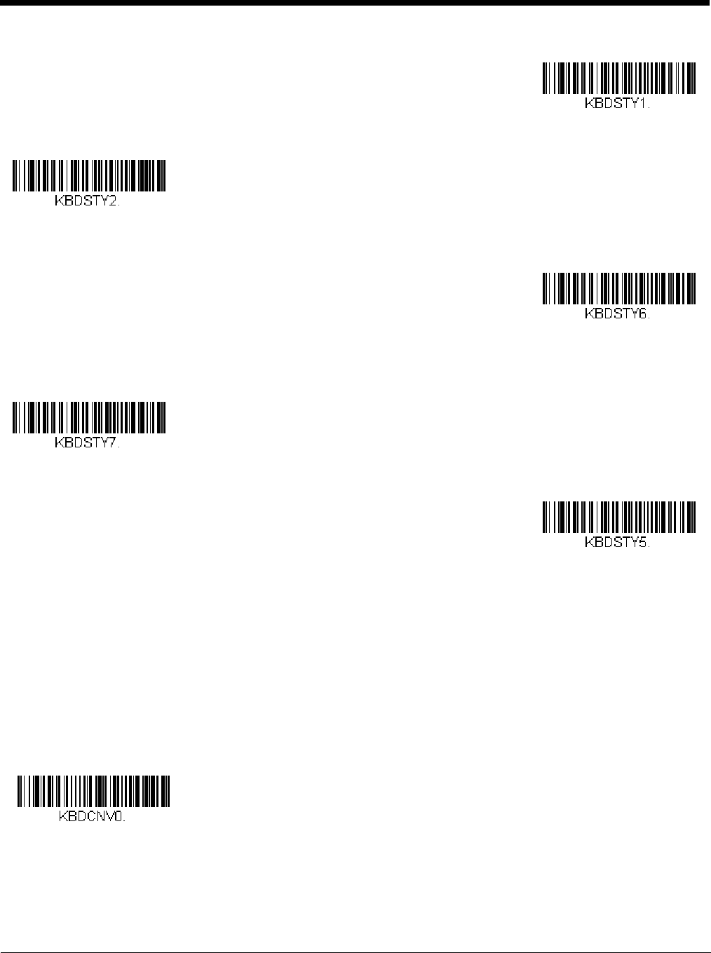
Keyboard Style
This programs keyboard styles, such as Caps Lock and Shift Lock. If you have used Keyboard Conversion settings, they will
override any of the following Keyboard Style settings. Default = Regular.
Regular is used when you normally have the Caps Lock key off.
Keyboard Countries (Continued)
Turkey F
Turkey Q
Ukrainian
United Kingdom
United States (Dvorak)
United States (Dvorak left)
United Stated (Dvorak right)
United States (International)
Uzbek (Cyrillic)
* Regular
Preliminary draft_1
2 - 15
Caps Lock is used when you normally have the Caps Lock key on.
Shift Lock is used when you normally have the Shift Lock key on (not common to U.S. keyboards).
Automatic Caps Lock is used if you change the Caps Lock key on and off. The software tracks and reflects if you have Caps
Lock on or off . This selection can only be used with systems that have an LED that notes the Caps Lock status (AT keyboards).
Autocaps via NumLock bar code should be scanned in countries (e.g., Germany, France) where the Caps Lock key cannot be
used to toggle Caps Lock. The NumLock option works similarly to the regular Autocaps, but uses the NumLock key to retrieve
the current state of the Caps Lock.
Emulate External Keyboard should be scanned if you do not have an external keyboard (IBM AT or equivalent).
Note: After scanning the Emulate External Keyboard bar code, you must power cycle your computer.
Keyboard Conversion
Alphabetic keyboard characters can be forced to be all upper case or all lowercase. So if you have the following bar code:
“abc569GK,” you can make the output “ABC569GK” by scanning Convert All Characters to Upper Case, or to “abc569gk” by
scanning Convert All Characters to Lower Case.
These settings override Keyboard Style selections.
Note: If your interface is a keyboard wedge, first scan the menu code for Automatic Caps Lock (page 2-15). Otherwise, your
output may not be as expected.
Default = Keyboard Conversion Off.
Caps Lock
Shift Lock
Automatic Caps Lock
Autocaps via NumLock
Emulate External Keyboard
* Keyboard Conversion Off
Preliminary draft_1

2 - 16
Control Character Output
This selection sends a text string instead of a control character. For example, when the control character for a carriage return is
expected, the output would display [CR] instead of the ASCII code of 0D. Refer to ASCII Conversion Chart (Code Page
1252) on page A-3. Only codes 00 through 1F are converted (the first column of the chart). Default = Off.
Note: Control + X (Control + ASCII) Mode overrides this mode.
Keyboard Modifiers
This modifies special keyboard features, such as CTRL+ ASCII codes and Turbo Mode.
Control + X (Control + ASCII) Mode On: The scanner sends key combinations for ASCII control characters for values 00-1F.
Windows is the preferred mode. All keyboard country codes are supported. DOS mode is a legacy mode, and it does not sup-
port all keyboard country codes. New users should use the Windows mode. Refer to Keyboard Function Relationships, page
9-1 for CTRL+ X Values.
Windows Mode Prefix/Suffix Off: The scanner sends key combinations for ASCII control characters for values 00-1F, but it
does not translate prefix or suffix information.
Default = Control + X Mode Off.
Convert All Characters
to Upper Case
Convert All Characters
to Lower Case
Control Character Output On
* Control Character Output Off
Windows Mode Control + X
Mode On
* Control + X Mode Off
DOS Mode Control + X Mode On
Preliminary draft_1

2 - 17
Turbo Mode: The scanner sends characters to a terminal faster. If the terminal drops characters, do not use Turbo Mode.
Default = Off.
Numeric Keypad Mode: Sends numeric characters as if entered from a numeric keypad. Default = Off.
Automatic Direct Connect Mode: This selection can be used if you have an IBM AT style terminal and the system is dropping
characters. Default = Off.
Windows Mode Prefix/Suffix Off
Turbo Mode On
* Turbo Mode Off
Numeric Keypad Mode On
* Numeric Keypad Mode Off
Automatic Direct Connect Mode
On
* Automatic Direct Connect
Mode Off
Preliminary draft_1

2 - 18
RS232 Modifiers
RS232 Baud Rate
Baud Rate sends the data from the scanner to the terminal at the specified rate. The host terminal must be set for the
same baud rate as the scanner. Default = 115,200.
300
600
1200
2400
4800
9600
19200
38400
57,600
* 115,200
Preliminary draft_1

2 - 19
RS232 Word Length: Data Bits, Stop Bits, and Parity
Data Bits sets the word length at 7 or 8 bits of data per character. If an application requires only ASCII Hex characters 0
through 7F decimal (text, digits, and punctuation), select 7 data bits. For applications that require use of the full ASCII set,
select 8 data bits per character. Default = 8.
Stop Bits sets the stop bits at 1 or 2. Default = 1.
Parity provides a means of checking character bit patterns for validity.
Default = None.
7 Data, 1 Stop, Parity Even
7 Data, 1 Stop, Parity None
7 Data, 1 Stop, Parity Odd
7 Data, 2 Stop, Parity Even
7 Data, 2 Stop Parity None
7 Data, 2 Stop, Parity Odd
8 Data, 1 Stop, Parity Even
* 8 Data, 1 Stop, Parity None
8 Data, 1 Stop, Parity Odd
8 Data, 1 Stop, Parity Mark
Preliminary draft_1
2 - 20
RS232 Receiver Time-Out
The unit stays awake to receive data until the RS232 Receiver Time-Out expires. A manual or serial trigger resets the time-
out. When an RS232 receiver is sleeping, a character may be sent to wake up the receiver and reset the time-out. A trans-
action on the CTS line will also wake up the receiver. The receiver takes 300 milliseconds to completely come up. Change
the RS232 receiver time-out by scanning the bar code below, then scanning digits from the inside back cover of this man-
ual, then scanning Save. The range is 0 to 300 seconds. Default = 0 seconds (no time-out - always on).
RS232 Handshaking
RS232 Handshaking allows control of data transmission from the scanner using software commands from the host device.
When RTS/CTS is turned Off, no data flow control is used.
Flow Control, No Timeout: The scanner asserts RTS when it has data to send, and will wait indefinitely for CTS to be
asserted by the host.
Two-Direction Flow Control: The scanner asserts RTS when it is OK for the host to transmit. The host asserts CTS
when it is OK for the device to transmit.
Flow Control with Timeout: The scanner asserts RTS when it has data to send and waits for a delay (see RS232
Timeout on page 2-20) for CTS to be asserted by the host. If the delay time expires and CTS is not asserted, the device
transmit buffer is cleared and scanning may resume. Default = RTS/CTS Off.
RS232 Timeout
When using Flow Control with Timeout, you must program the length of the delay you want to wait for CTS from the host.
Set the length (in milliseconds) for a timeout by scanning the bar code below, then setting the timeout (from 1-5100 millisec-
onds) by scanning digits from the inside back cover, then scanning Save.
RS232 Receiver Time-Out
Flow Control, No Timeout
Two-Direction Flow Control
Flow Control with Timeout
* RTS/CTS Off
RS232 Timeout
Preliminary draft_1

2 - 21
XON/XOFF
Standard ASCII control characters can be used to tell the scanner to start sending data (XON/XOFF On) or to stop sending
data (XON/XOFF Off). When the host sends the XOFF character (DC3, hex 13) to the scanner, data transmission stops.
To resume transmission, the host sends the XON character (DC1, hex 11). Data transmission continues where it left off
when XOFF was sent. Default = XON/XOFF Off.
ACK/NAK
After transmitting data, the scanner waits for an ACK character (hex 06) or a NAK character (hex 15) response from the
host. If ACK is received, the communications cycle is completed and the scanner looks for more bar codes. If NAK is
received, the last set of bar code data is retransmitted and the scanner waits for ACK/NAK again. Turn on the ACK/NAK
protocol by scanning the ACK/NAK On bar code below. To turn off the protocol, scan ACK/NAK Off. Default = ACK/NAK
Off.
Scanner to Bioptic Communication
The following settings are used to set up communication between Honeywell scanners and bioptic scanners.
Note: The scanner’s baud rate must be set to 38400 and the RS232 timeout must be set to 3000 in order to communicate with
a bioptic scanner. See "RS232 Modifiers" on page 2-18, and RS232 Timeout on page 2-20 for further information.
Scanner-Bioptic Packet Mode
Packet Mode On must be scanned to set the scanner’s format so it is compatible with a bioptic scanner. Default = Packet
Mode Off.
XON/XOFF On
* XON/XOFF Off
ACK/NAK On
* ACK/NAK Off
* Packet Mode Off
Packet Mode On
Preliminary draft_1

2 - 22
Scanner-Bioptic ACK/NAK Mode
Bioptic ACK/NAK On must be scanned so the scanner will wait for an ACK or NAK from a bioptic scanner after each
packet is sent. The Scanner-Bioptic ACK/NAK Timeout (below) controls how long the scanner will wait for a response.
Default = Bioptic ACK/NAK Off.
Scanner-Bioptic ACK/NAK Timeout
This allows you to set the length (in milliseconds) for a timeout for a bioptic scanner’s ACK/NAK response. Scan the bar
code below, then set the timeout (from 1-30,000 milliseconds) by scanning digits from the inside back cover, then scanning
Save. Default = 5100.
* Bioptic ACK/NAK Off
Bioptic ACK/NAK On
ACK/NAK Timeout
Preliminary draft_1
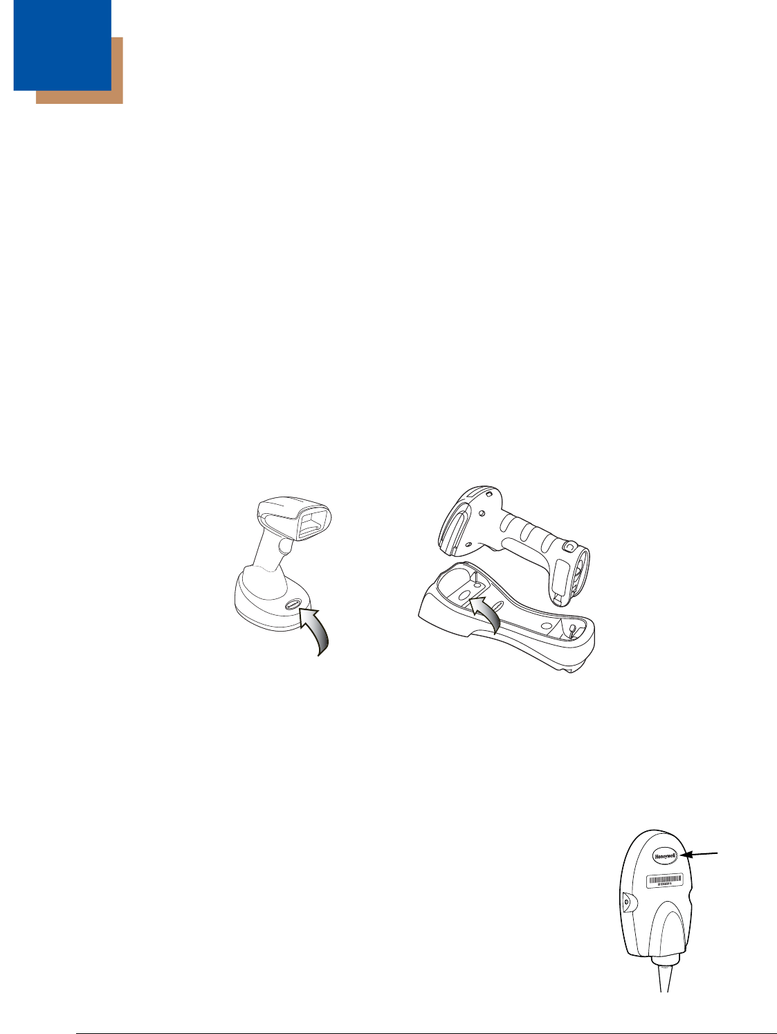
3 - 1
3
Cordless System Operation
Note: This chapter applies only to cordless scanning systems. It does not apply to corded scanners.
How the Cordless Charge Base/Access Point Works
A cordless charge base or an Access Point provide the link between the cordless scanner and the host system. The base/
Access Point contains an interface assembly and an RF communication module. The RF communication module performs the
data exchange between the cordless scanner and the interface assembly. The control assembly coordinates the central inter-
face activities including: transmitting/receiving commands and data to/from the host system, performing software activities
(parameter menuing, visual indicator support, power-on diagnostics), and data translation required for the host system.
The cordless charge base is also a scanner’s battery charger. Refer to Charging Information, page 3-4, for additional informa-
tion.
Linking the Scanner to a Charge Base
Turn off power before connecting a base, then power up the computer once the base is fully connected. When the base is con-
nected and powered up, put the scanner in the base to establish a link. The green LED on the base flashes to indicate the scan-
ner’s battery is charging.
If the scanner and base have previously been linked, you do not receive any feedback. If this is the first time that the scanner
and base are linked, both devices emit a short chirp when their radios link. At this point, that one scanner is linked to one base.
To determine if your cordless system is set up correctly, scan one of the sample bar codes in the back of this manual. If the
scanner provides a single good read beep and the green LED lights, the scanner has successfully linked to the base. If using
a Granit scanner, the scanner also vibrates. If you receive an error tone and the red LED lights, the scanner has not linked to
the base. Refer to page 13-4 for troubleshooting information.
Linking the Scanner to an Access Point
Turn on the computer (laptop/desktop). Plug the interface cable into the Access Point first and
then into the appropriate port on the computer. The Page button lights up when the connection to
the host is made.
Xenon Scanner
CCB01-010BT Charge Base
Page Button and Base LEDs
Granit Scanner
CCB02-100BT Charge Base
Page Button and Base LEDs
Page
Button
Preliminary draft_1
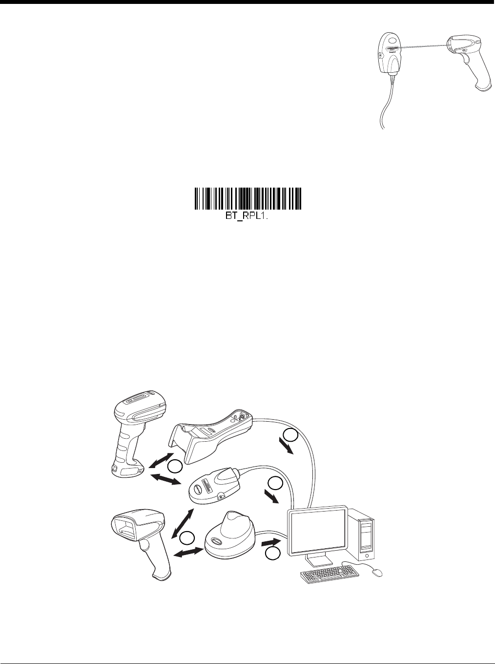
3 - 2
Scan the linking bar code on the top of the Access Point to establish a connection between the
Access Point and the scanner. The scanner emits a short beep and flashes the green LED to
confirm a connection with the Access Point. The Access Point’s Page button remains blue.
Replacing a Linked Scanner
If you need to replace a broken or lost scanner that is linked to a base or an Access Point, scan the Override Locked Scanner
bar code below with a new scanner and place that scanner in the base, or scan the Access Point linking bar code. The locked
link will be overridden; the broken or lost scanner’s link with the base or Access Point will be removed, and the new scanner will
be linked.
Communication Between the Cordless System
and the Host
The cordless scanner provides immediate feedback in the form of a “good read” indication with a green LED on the scanner and
an audible beep. If using a Granit scanner, the scanner also vibrates. This indicates that the bar code has been scanned cor-
rectly and the base or Access Point has acknowledged receiving the data. This is possible since the cordless system provides
two-way communication between the scanner and the base or Access Point.
When data is scanned, the data is sent to the host system via the base or Access Point. The cordless scanner recognizes data
acknowledgement (ACK) from the base or Access Point. If it cannot be determined that the data has been properly sent to the
base or Access Point, the scanner issues an error indication. You must then check to see if the scanned data was received by
the host system.
1. Scanner reads code and gets ACK from base or Access Point
2. Base or Access Point sends data to host
Override Locked Scanner
(Single Scanner)
2
1
1
2
2
Preliminary draft_1

3 - 3
Programming the Scanner and Base or Access Point
When using the scanner and charge base or Access Point together as a system, menu parameters and configuration settings
are stored in the charge base or Access Point. Therefore, when programming any menu configuration settings, the scanner
must be linked to the intended charge base or Access Point.
Note: This only applies when the scanner is linked to a charge base or Access Point. If the scanner is in a non-base mode,
configuration settings are stored in the scanner.
RF (Radio Frequency) Module Operation
The cordless system uses a two-way Bluetooth® radio to transmit and receive data between the scanner and the base or
Access Point. Designed for point-to-point and multipoint-to-single point applications, the radio operates using a license free ISM
band, which sends relatively small data packets at a fast data rate over a radio signal with randomly changing frequencies,
makes the cordless system highly responsive to a wide variety of data collection applications and resistant to noisy RF environ-
ments. The CCB01-010BT (Bluetooth Class 2) provides a communication range of 33 feet (10m) between the scanner and
base or Access Point, depending on the environment. The CCB02-100BT (Bluetooth Class 1) provides a communication range
of 330 feet (100m) between the scanner and base or Access Point, depending on the environment. See Flexible Power
Management, page 3-12, for information about controlling this range.
System Conditions
The components of the cordless system interact in specific ways as you associate a scanner to a base or Access Point, as you
move a scanner out of range, bring a scanner back in range, or swap scanners between two cordless systems. The following
information explains the cordless system operating conditions.
Linking Process
Once a scanner is placed into a cordless charge base, the scanner’s battery charge status is checked, and software auto-
matically detects the scanner and links it to the base depending on the selected link mode.
Refer to Linking the Scanner to an Access Point, page 3-1, for information about linking to an Access Point.
Scanner Is Out of Range
The cordless scanner is in communication with its base or Access Point, even when it is not transmitting bar code data.
Whenever the scanner can’t communicate with the base or Access Point for a few seconds, it is out of range. If the scanner
is out of range and you scan a bar code, the scanner issues an error tone indicating no communication with the base or
Access Point. A cordless charge base can also sound an alarm. Refer to Out-of-Range Alarm, page 3-10.
Scanner Is Moved Back Into Range
The scanner relinks if the scanner or the base or Access Point have been reset, or the scanner comes back into range. If
the scanner relinks, you will hear a single chirp when the relinking process (uploading of the parameter table) is complete.
Refer to Out-of-Range Alarm on page 3-10 for further information.
Out of Range and Back into Range with Batch Mode On
The scanner may store a number of symbols (approximately 500 U.P.C. symbols; others may vary) when it is out of range
and then send them to the base or Access Point when back in range (see Batch Mode on page 3-13).
You will not hear a communication error tone in this mode, but you will hear a short buzz when you pull the trigger if the
radio communication is not working. Once the radio connection is made, the scanner produces a series of beeps while the
data is being transferred to the base or Access Point.
Page Button
When you press the Page button on the base or Access Point, the scanners associated with that base or Access Point will
begin beeping (3 short and 1 long beep). If you pull the trigger on a scanner that is beeping in response, or press the Page
button on the base or Access Point a second time, all associated scanners will stop beeping. See Paging on page 3-7 for
further information about Page Button settings.
Preliminary draft_1

3 - 4
About the Battery
There is a danger of explosion if the batteries are incorrectly replaced. Replace the batteries with only the same or
equivalent type recommended by the manufacturer. Dispose of used batteries according to the recycle program for
batteries as directed by the governing agency for the country where the batteries are to be discarded.
Power is supplied to the cordless scanner by a rechargeable battery that is integrated in the scanner handle. Batteries are
shipped approximately 30% to 60% charged. The battery should be charged for a minimum of 4 hours before initial use to
ensure optimal performance.
Charging Information
The battery is designed to charge while the scanner is positioned in the cordless base unit. Refer to Base/Access Point
LED Sequences and Meaning, page 3-5, for an interpretation of the Charge Status indicators. Refer to Charge Only Mode
(page 3-9) if you need to charge a scanner without linking it to the base.
Place the scanner in the base that is connected to an appropriate power supply. Use only a Listed Limited Power Source
(LPS) or Class 2 type power supply with output rated 5 to 5.2Vdc, 1A.
Note: If you are powering the base through the interface cable (for example, a USB cable) and not using an external power
supply plugged into the aux port, the current available for charging is reduced and charge times are increased.
Battery Recommendations
• The battery is a lithium ion cell and can be used without a full charge, and can also be charged without fully discharging,
without impacting the battery life. There is no need to perform any charge/discharge conditioning on this type of battery.
• Keep the base connected to power when the host is not in use.
• Replace a defective battery immediately since it could damage the scanner.
• Although your battery can be recharged many times, it will eventually be depleted. Replace it after the battery is unable
to hold an adequate charge.
• If you are not sure if the battery or charger is working properly, send it to Honeywell International Inc. or an authorized
service center for inspection. Refer to Customer Support on page 14-1 for additional information.
Caution:
Use only Honeywell Li-ion battery packs, model number BAT-SCN01, rated 3.7 Vdc, 7.4Whr in this device. Use
of any non-Honeywell battery may result in damage not covered by the warranty.
Safety Precautions for Lithium Batteries
• Do not place batteries in fire or heat the batteries.
• Do not store batteries near fire or other high temperature locations.
• Do not store or carry batteries together with metal objects.
• Do not expose batteries to water or allow the batteries to get wet.
• Do not connect (short) the positive and negative terminals, of the batteries, to each other with any metal object.
• Do not pierce, strike or step on batteries or subject batteries to strong impacts or shocks.
• Do not disassemble or modify batteries.
Caution:
Danger of explosion if batteries are incorrectly replaced. Dispose of used batteries according to the recycle
program for batteries as directed by the governing agency for the country where the batteries are to be
discarded.
Proper Disposal of the Battery
When the battery has reached the end of its useful life, the battery should be disposed of by a qualified
recycler or hazardous materials handler. Do not incinerate the battery or dispose of the battery with gen-
eral waste materials. You may send the scanner’s battery to us. (postage paid). The shipper is respon-
sible for complying with all federal, state, and local laws and regulations related to the packing, labeling,
manifesting, and shipping of spent batteries. Contact the Product Service Department (page 14-1) for
recycling or disposal information. Since you may find that your cost of returning the batteries significant,
it may be more cost effective to locate a local recycle/disposal company.
!
!
!
Preliminary draft_1
3 - 5
Beeper and LED Sequences and Meaning
The scanner contains LEDs on the rear of the unit that indicate linking status, decoding state, and battery condition. The base
has LEDs on the top of the unit that indicate its power up, communication, and battery charge condition. The red LED = error;
green LED = success of any type. Scanners and the CCB01-010BT base have audible indicators as well: 1 razz or error tone =
error; 2 beeps = menu change; 1 beep = all other successes.
The table below lists the indication and cause of the LED indication, beeps, and vibrations for the scanner.
Scanner LED Sequences and Meaning
Base/Access Point LED Sequences and Meaning
The base contains a red LED and the Access Point has a blue LED that indicate the status of the unit and verifies its com-
munication with the host system. The base also has a green LED that indicates scanner battery charge condition.
Base Power Communication Indicator
To display the power indicator on a base or an Access Point, scan the Base Power Communication Indicator On bar
code. To turn off the power indicator, scan the Off bar code. Default = On.
LED Indication Beeper Indication Vibrate Indication Cause
Normal Operation
Red Flash None None Battery low
Green Flash 1 beep None Successful communication or linking
Red, blinking Razz or error tone None Failed communication
Menu Operation
Green Flash 2 beeps 2 vibrations Successful menu change
Red, blinking Razz or error tone 1 long vibration Unsuccessful menu change
Red or Blue LED - Host Communication
Red or Blue LED Communication Condition
Off USB suspend
On continuously Power on, system idle
Short blinks in multiple pulses. Occurs while transferring data to/
from the RF module or the Host port.
Receiving data
Green LED - Scanner Battery
(base only, does not apply to Access Point)
Green LED Charge Condition
Off Battery not detected or charge suspended
Slow flash, 1 second on, 1 second off Pre-charge and charging
On continuously Charge complete
Fast flash, 300 mSec on, 300 mSec off Charge Error
* Base Power Communication
Indicator On
Preliminary draft_1
3 - 6
Reset Scanner
Scanning this bar code reboots the scanner and causes it to relink with the base or Access Point.
Scanning While in Base Cradle
Note: This feature only applies to the CCB01-010BT base.
If you want to be able to scan bar codes while the scanner is in the base cradle, scan the Scanning in Cradle On bar code
below. If you want to only allow scanning when the scanner is out of the base cradle, scan Scanning in Cradle Off. If you want
the scanner to shut down when in the base cradle, scan Shut Down Scanner in Cradle. Default = Scanning in Cradle On (for
CCB01-010BT).
Base Charging Modes
When the base has both an external power supply (plugged into the auxiliary power port) and a host interface cable, it will draw
its power from the external power supply. When the base does not have an external power supply, it draws its power from the
interface cable. However, the scanner battery charges more slowly from a host interface cable than if auxiliary power were
available. Using the following selections, you can specify whether the scanner battery is charged from power supplied via the
host interface cable.
When Base Charge Off is selected, the scanner battery does not charge when the scanner is in the base cradle.
When External or Interface Cable Power is selected, the scanner battery charges from the base’s external power supply, if
there is one. If there is no external power supply to the base, the scanner battery charges from the interface cable.
When External Power Only is selected, the scanner battery only charges from the base’s external power supply. If there is no
external power supply, the scanner battery does not charge.
Note: If you are using a cordless charge base in Presentation Mode, External Power Only is the only setting available.
Base Power Communication
Indicator Off
Reset Scanner
Scanning in Cradle Off
* Scanning in Cradle On
Shut Down Scanner in Cradle
Preliminary draft_1
3 - 7
Default = External or Interface Cable Power.
Paging
Paging Mode
By default, the paging button on the base or Access Point pages the scanners associated with that base or Access Point. If
you want the paging button on your base or Access Point to be disabled, scan the Paging Mode Off bar code, below.
When Paging Mode is off, the base or Access Point will no longer page scanners when the button is pressed. The red LED
on the base or blue LED on the Access Point will remain lit to indicate that Paging Mode is off. (This light will go out when
the button is pressed, then back on when it’s released.) Default = Paging Mode On.
Paging Pitch
When you press the Page button on the base or Access Point, the scanners associated with that base or Access Point will
begin beeping (see Page Button on page 3-3). You can set the pitch of the paging beep for each scanner by scanning one
of the following bar codes. Default = Low.
Base Charge Off
External or Interface Cable
Power
External Power Only
* Paging Mode On
Paging Mode Off
* Low (1000 Hz)
Medium (3250 Hz)
Preliminary draft_1

3 - 8
Error Indicators
Beeper Pitch - Base Error
Note: This feature only applies to the CCB01-010BT base.
The CCB01-010BT base can be configured to beep at a particular pitch when an error occurs, such as transmission prob-
lems to a host system. The beeper pitch codes modify the pitch (frequency) of the error tone the base emits when there is
an error. Default = Low.
Number of Beeps - Base Error
Note: This feature only applies to the CCB01-010BT base.
The number of beeps and LED flashes emitted by the CCB01-010BT base for an error condition can be programmed from
1 - 9. For example, if you program this option to have five error beeps, there will be five error beeps and five LED flashes in
response to an error. To change the number of error beeps, scan the bar code below and then scan a digit (1-9) bar code
and the Save bar code on the Programming Chart inside the back cover of this manual. Default = 1.
Scanner Report
Scan the bar code below to generate a report for the connected scanners. The report indicates the port, work group, scanner
name, and address. To assign a name to your scanner, refer to Menu Command Syntax, page 11-1.
High (4200 Hz)
* Razz (250 Hz)
Medium (3250 Hz)
High (4200 Hz)
Number of Base Error Beeps/LED Flashes
Scanner Report
Preliminary draft_1
3 - 9
Scanner Address
Scan the bar code below to determine the address of the scanner you are using.
Base or Access Point Address
Scan the bar code below to determine the address of the base or Access Point you are using.
Scanner Modes
Your scanner is capable of working in single scanner mode, multiple scanner mode, or with Bluetooth devices other than the
charge base or Access Point.
Charge Only Mode
There may be times when you want to charge your scanner, but not link to the base. For example, if a scanner is linked to
an Access Point or other Bluetooth device and you need to charge the scanner, but want to retain your existing link.
In order to program the base for Charge Only Mode, you must link a scanner to it. Once the scanner is linked to the base,
scan the Charge Only Mode bar code. Any subsequent scanners placed in that base will charge without linking to it. The
scanner used to program the base remains linked to the base. To unlink this scanner, scan Unlink Scanner on page 3-10.
Note: When in Charge Only Mode, the scanner periodically wakes up and beeps. See "Power Up Beeper" on page 4-1 to
change this setting.
If you want to charge a scanner and link to the base, use Charge and Link Mode. If the base is programmed for Charge
Only Mode, you must link a scanner to it first in order to program it for Charge and Link Mode. Scan the linking bar code on
the base to link the scanner, then scan Charge and Link Mode. Default = Charge and Link Mode.
Linked Modes
Locked Link Mode and Open Link Mode are the link modes that accommodate different applications. Scan the appropriate
bar codes included in the Open Link and Locked Link Mode explanations that follow to switch from one mode to another.
Default = Open Link Mode.
Scanner Address
Base Address
Charge Only Mode
* Charge and Link Mode
Preliminary draft_1

3 - 10
Locked Link Mode - Single Scanner
If you link a scanner to a base or an Access Point using the Locked Link Mode, other scanners are blocked from being
linked if they are inadvertently placed into the base, or if the Access Point linking bar code is scanned. If you do place
a different scanner into a base, it will charge the scanner, but the scanner will not be linked.
To use a different scanner, you need to unlink the original scanner by scanning the Unlink Scanner bar code. (See
Scanner Modes, page 3-9.)
Open Link Mode - Single Scanner
When newly shipped or defaulted to factory settings, a scanner is not linked to a base or an Access Point. A link is
established when the scanner is placed into a base, or an Access Point linking bar code is scanned. When in Open
Link Mode, a new link is established when a new scanner is placed in the base, or you scan an Access Point linking bar
code. Each time a scanner is placed into a base or scans an Access Point linking bar code, the scanner becomes
linked to the base or Access point and the old scanner is unlinked.
Unlinking the Scanner
If a base or an Access Point has a scanner linked to it, that scanner must be unlinked before a new scanner can be linked.
Once the previous scanner is unlinked, it will no longer communicate with the base or Access Point. To unlink the scanner from
a base or an Access Point, scan the Unlink Scanner bar code below.
Override Locked Scanner
If you need to replace a broken or lost scanner that is linked to a base or an Access Point, scan the Override Locked
Scanner bar code below with a new scanner and place that scanner in the base, or scan the Access Point linking bar code.
The locked link will be overridden; the broken or lost scanner’s link with the base or Access Point will be removed, and the
new scanner will be linked.
Out-of-Range Alarm
If your scanner is out range of the base, an alarm sounds from both your base and scanner. If your scanner is out range of an
Access Point, an alarm sounds from just the scanner. The alarm stops when the scanner is moved closer to the base or Access
Point, when the base or Access Point connects to another scanner, or when the alarm duration expires. To activate the alarm
Locked Link Mode
(Single Scanner)
* Open Link Mode
(Single Scanner)
Unlink Scanner
Override Locked Scanner
(Single Scanner)
Preliminary draft_1
3 - 11
options for the scanner or the base and to set the alarm duration, scan the appropriate bar code below and then set the time-out
duration (from 0-3000 seconds) by scanning digits on the Programming Chart inside the back cover, then scanning Save.
Default = 0 sec (no alarm).
Note: If you are out of range when you scan a bar code, you will receive an error tone even if you do not have the alarm set.
You receive the error tone since the data could not be communicated to the base or Access Point or the host.
Alarm Sound Type
You may change the alarm type for the scanner or a CCB01-010BT base by scanning the appropriate bar code below and
then scanning a digit (0-7) bar code and the Save bar code on the Programming Chart inside the back cover of this manual.
Default = 0.
The sounds are as follows:
Scanner Power Time-Out Timer
Note: Scanner Power Time-out Timer only applies to cordless systems. It does not apply to corded scanners.
Note: The Access Point does not have a base alarm.
Setting Sound
0 3 long beeps, medium pitch
1 3 long beeps, high pitch
2 4 short beeps, medium pitch
3 4 short beeps, high pitch
4 single chirps, medium pitch
5 2 chirps, then 1 chirp, medium pitch
6 single chirps, high pitch
7 2 chirps, then 1 chirp, high pitch
Note: Only the CCB01-010BT base has an alarm.
Base Alarm Duration
Scanner Alarm Duration
Base Alarm Type
Scanner Alarm Type
Preliminary draft_1
3 - 12
When there is no activity within a specified time period, the scanner enters low power mode. Scan the appropriate scanner
power time-out bar code to change the time-out duration (in seconds).
Note: Scanning zero (0) is the equivalent of setting no time-out.
If there are no trigger pulls during the timer interval, the scanner goes into power down mode. Whenever the trigger is enabled,
the timer is reset. If the scanner is placed in the charge base cradle and the battery is in the process of being charged, the
scanner will not go into power down mode. Default = 3600 seconds.
Note: When the scanner is in power down mode, pull the trigger to power the unit back up. There will be a set of power up beeps
and a delay of up to a few seconds for the radio to join. The scanner will then be ready to use.
Flexible Power Management
If you are experiencing network performance issues, and suspect the scanner is interfering with other devices, you can turn
down the power output of the scanner. This reduces the range between the scanner and a base or an Access Point as shown
in the following illustration:
0 seconds
200 seconds
400 seconds
900 seconds
* 3600 seconds
7200 seconds
F
u
l
l
P
o
w
e
r
R
e
d
u
c
e
d
P
o
w
e
r
1902
Scanner
802.11
LAN
Preliminary draft_1
3 - 13
Scan one of the bar codes below to set the scanner’s power output to Full Power (100%), Medium Power (35%), Medium Low
Power (5%), or Low Power (1%). Default = Full Power.
Note: Setting a Granit scanner to anything lower than Full Power changes it to Class II Bluetooth.
Batch Mode
Batch mode is used to store bar code data when a scanner is out of range of its base or Access Point, or when performing
inventory. The data is transmitted to the base or Access Point once the scanner is back in range or when the records are man-
ually transmitted.
Note: Batch mode has limitations when using multiple scanners to one base or Access Point. If a cordless system is being used
in "multiple link mode," where up to 7 scanners are to be connected to one base or Access Point, some accumulated or
batched scans could be lost if scanners are constantly being moved in and out of range.
Automatic Batch Mode stores bar code data when the scanner is out of range of the base or Access Point. The data is auto-
matically transmitted to the base or Access Point once the scanner is back in range. When the scanner’s buffer space is full,
any bar codes scanned generate an error tone. In order to scan bar codes again, the scanner must be moved back into range
of the base or Access Point so data can be transmitted.
Inventory Batch Mode stores bar code data, whether or not you are in range of the base or Access Point. To transmit the
stored data to the base or Access Point, either place the scanner in the base, or scan Transmit Inventory Records (page 3-17).
When the scanner’s buffer space is full, any bar codes scanned generate an error tone. In order to scan bar codes again, the
data must be transmitted to the base or Access Point. Once the data is transmitted, it is cleared in the scanner.
Persistent Batch Mode is the same as Inventory Batch Mode, except that once the data is transmitted to the base or Access
Point, it is retained in the scanner. If you want to transmit more than once, you can do so using this mode. In order to clear the
scanner’s buffer, you must scan Clear All Codes (see page 3-17).
Default = Batch Mode Off.
* Full Power
Medium Power
Medium Low Power
Low Power
* Batch Mode Off
Automatic Batch Mode
Preliminary draft_1
3 - 14
Batch Mode Beep
When scanning in Inventory Batch Mode (page 3-14), the scanner beeps every time a bar code is scanned. If using a
Granit scanner, it also vibrates. When Batch Mode Beep is On, you will also hear a click when each bar code is sent to
the host. If you do not want to hear these clicks, scan Batch Mode Beep Off. Default = Batch Mode Beep On.
Batch Mode Storage
When a scanner is storing data during a Batch Mode process, you can select whether the data is stored in Flash memory
or in RAM.
Flash Storage: The scanner writes any untransmitted data to flash memory prior to powering down. The data will still be
there when the scanner powers back up. However, the scanner will power down, even with untransmitted data, if it reaches
a power down timeout or if the battery power is very low.
RAM Storage: The scanner will not power down while it contains data that has not been transmitted to the base or Access
Point, even if it reaches a power down timeout. However, if the scanner runs out of battery power, it will power down and
the data will be lost.
Default = Flash Storage.
Inventory Batch Mode
Persistent Batch Mode
Batch Mode Beep Off
* Batch Mode Beep On
* Flash Storage
RAM Storage
Preliminary draft_1

3 - 15
Batch Mode Quantity
When in Batch Mode, you may wish to transmit the number of multiple bar codes scanned, rather than a single bar code
multiple times. For example, if you scan three bar codes called XYZ with Batch Mode Quantity Off, when you transmit
your data it will appear as XYZ three times. Using Batch Mode Quantity On and the Quantity Codes (page 3-16), you
could output your data as “XYZ, 00003” instead.
Note: If you wish to format your output, for example, place a CR or tab between the bar code data and the quantity, refer
to Data Formatting beginning on page 6-1.
Default = Batch Mode Quantity Off.
Entering Quantities
Quantity Codes (page 3-16) allow you to enter a quantity for the last item scanned, up to 9999 (default = 1). Quantity digits
are shifted from right to left, so if a 5th digit is scanned, the 1st digit scanned is discarded and the 2nd, 3rd and 4th digits are
moved to the left to accommodate the new digit.
For example, if the Quantity 5 bar code is scanned after the quantity has been set to 1234, then the 1 is dropped, the quan-
tity will be 2345.
Example: Add a quantity of 5 for the last item scanned.
1. Scan the item's bar code.
2. Scan the quantity 5 bar code.
Example: Add a quantity of 1,500 for the last item scanned.
1. Scan the item's bar code.
2. Scan the quantity 1 bar code.
3. Scan the quantity 5 bar code.
4. Scan the quantity 0 bar code.
5. Scan the quantity 0 bar code.
Example: Change a quantity of 103 to 10.
To correct an incorrect quantity, scan the quantity 0 bar code to replace the incorrect digits, then scan the correct quantity
bar codes.
1. Scan the quantity 0 bar code to change the quantity to 1030.
2. Scan the quantity 0 bar code to change the quantity to 0300.
3. Scan the quantity 1 bar code to change the quantity to 3001.
4. Scan the quantity 0 bar code to change the quantity to 0010.
Default = 1.
Quantity Codes
* Batch Mode Quantity Off
Batch Mode Quantity On
0
Preliminary draft_1
3 - 16
Batch Mode Output Order
When batch data is transmitted, select whether you want that data sent as FIFO (first-in first-out), or LIFO (last-in first-out).
Default = Batch Mode FIFO.
1
2
3
4
5
6
7
8
9
* Batch Mode FIFO
Batch Mode LIFO
Preliminary draft_1
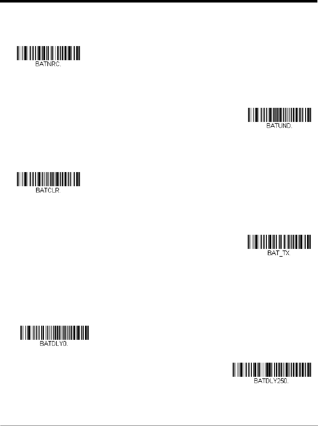
3 - 17
Total Records
If you wish to output the total number of bar codes scanned when in Batch Mode, scan Total Records.
Delete Last Code
If you want to delete the last bar code scanned when in Batch Mode, scan Delete Last Code.
Clear All Codes
If you want to clear the scanner’s buffer of all data accumulated in Batch Mode, scan Clear All Codes.
Transmit Records to Host
If you are operating in Inventory Batch Mode (see Inventory Batch Mode on page 3-14), you must scan the following bar
code to transmit all the stored data to the host system.
Batch Mode Transmit Delay
Sometimes when accumulated scans are sent to the host system, the transmission of those scans is too fast for the appli-
cation to process. To program a transmit delay between accumulated scans, scan one of the following delays. Default =
Off.
Note: In most cases, a short (250 ms (milliseconds)) delay is ideal, however, longer delays may be programmed. Contact
Technical Support (page 14-1) for additional information.
Total Records
Delete Last Code
Clear All Codes
Transmit Inventory Records
* Batch Mode Transmit Delay Off
(No Delay)
Batch Mode Transmit Delay Short
(250 ms)
Preliminary draft_1

3 - 18
Multiple Scanner Operation
Note: Multiple Scanner Operation Mode allows you to link up to 7 scanners to one base or Access Point. You cannot join an
8th scanner until you unlink one of the 7 scanners or take a scanner out of range.
To put the scanner in multiple scanner mode, scan the bar code below. Once you scan this bar code, the scanner is unlinked
from the base or Access Point and must either be placed into the base, or you must scan the Access Point linking bar code in
order to relink.
Scanner Name
You may assign a name to each scanner you are using for identification purposes. For example, you may want to have a unique
identifier for a scanner that is receiving imaging commands sent from the base or Access Point.
The default name is in the format “ScannerName_Model_SN_XXXXXXXXXX” If you have more than one scanner linked to a
base, and they all have the same name, the first scanner linked to the base receives commands. When renaming a series of
scanners with identical names, unlink all except one of the scanners from the base.
Perform the rename operation using either the bar codes on page 3-19, or by sending the serial command :Scanner-
Name:BT_NAMNewName. where ScannerName is the current name of the scanner, and NewName is the new name for the
scanner. If you wish to change the names of additional scanners, link them one at a time and repeat the :ScannerName:BT_N-
AMNewName. command for each scanner.
To rename scanners with sequential, numeric names, scan the bar codes below. Scan the Reset code after each name change
and wait for the scanner to relink to the base or Access Point before scanning a bar code to rename the next scanner.
Batch Mode Transmit Delay Medium
(500 ms)
Batch Mode Transmit Delay Long
(1000 ms)
Multiple Scanner Operation
0001
0002
0003
Preliminary draft_1
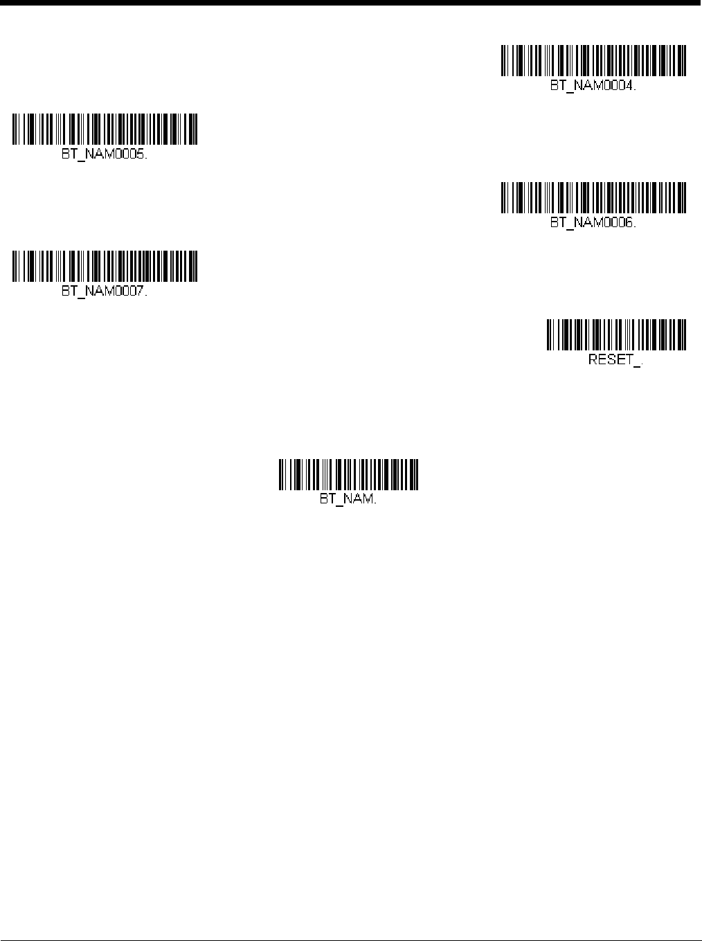
3 - 19
You may also scan the Scanner Name bar code below and scan a number for the scanner name. For example, if you wanted to
name the linked scanner “312,” you would scan the bar code below, scan the 3, 1, and 2 bar codes on the Programming Chart
inside the back cover of this manual, then scan Save. Scan the Reset bar code and wait for the scanner to relink to the base.
Application Work Groups
Your cordless system can have up to 7 scanners linked to one base or Access Point. You can also have up to 7 work groups. If
you want to have all of the scanners’ settings programmed alike, you don’t need to use more than 1 work group. If you want
each scanner to have unique settings (e.g., beeper volume, prefix/suffix, data formatter), then you may program each scanner to
its own unique work group and may program each scanner independently. For example, you might want to have multiple work
groups in a retail/warehouse application where you need to have different data appended to bar codes used in the warehouse
area versus the retail area. You could assign all the scanners in the retail area to one work group and those in the warehouse to
another. Consequently, any desired changes to either the retail or warehouse area would apply to all scanners in that particular
work group. Honeywell’s online configuration tool, EZConfig-Scanning (page 10-2), makes it easy for you to program your sys-
tem for use with multiple scanners and multiple work groups.
The scanner keeps a copy of the menu settings it is using. Whenever the scanner is connected or reconnected to a base or an
Access Point, the scanner is updated with the latest settings from the base or Access Point for its work group. The scanner also
receives menu setting changes processed by the base or Access Point. If a scanner is removed from a base or an Access Point
and placed into another base or linked to another Access Point, it will be updated with the new base/Access Point settings for
whatever work group to which that the scanner was previously assigned. For example, if the scanner was in work group 1 linked
to the first base, it will be placed in work group 1 in the second base with the associated settings.
0004
0005
0006
0007
Reset
Scanner Name
Preliminary draft_1
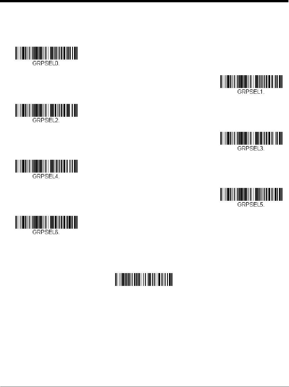
3 - 20
Application Work Group Selection
This programming selection allows you to assign a scanner to a work group by scanning the bar code below. You may then
program the settings (e.g., beeper volume, prefix/suffix, data formatter) that your application requires. Default = Group 0.
Resetting the Factory Defaults: All Application Work Groups
The following bar code defaults all of the work groups to the factory default settings.
To see what the factory default settings are, refer to the table of Menu Commands, beginning on page 11-4. The standard prod-
uct default settings for each of the commands are indicated by an asterisk (*).
Note: Scanning this bar code also causes both the scanner and the base or Access Point to perform a reset and become
unlinked. The scanner must be placed in the base, or the Access Point linking bar code must be scanned to re-establish
the link. Refer to Scanner Modes, page 3-9 for additional information.
If your scanner is in multiple scanner mode, you will hear up to 30 seconds of beeping while all scanners are relinked to
the base or Access Point and the settings are changed.
* Group 0
Group 1
Group 2
Group 3
Group 4
Group 5
Group 6
Factory Default Settings:
All Work Groups
PAPDFT&
Preliminary draft_1

3 - 21
Resetting the Custom Defaults: All Application Work Groups
If you want the custom default settings restored to all of the work groups, scan the Custom Product Default Settings bar code
below. (If there are no custom defaults, it will reset the work groups to the factory defaults.) See "Setting Custom Defaults" on
page 1-11 for further information about custom defaults.
Note: Scanning this bar code also causes both the scanner and the base or Access Point to perform a reset and become
unlinked. The scanner must be placed in its base, or the Access Point linking bar code must be scanned to re-establish
the link. Refer to Scanner Modes, page 3-9 for additional information.
If your scanner is in multiple scanner mode, you will hear up to 30 seconds of beeping while all scanners are relinked to
the base or Access Point and the settings are changed.
Using the Scanner with Bluetooth Devices
The scanner can be used either with the charge base, an Access Point, or with other Bluetooth devices. Those devices include
personal computers, laptops, PDAs, and Honeywell mobility systems devices.
Bluetooth HID Keyboard Connect
Your scanner can be paired with Bluetooth-capable devices, such as iPads, smart phones, and laptops, so that scanned
data appears on your device screen as though it was entered on the keyboard. In order to pair with the Bluetooth device:
1. Scan the Bluetooth HID Keyboard Connect bar code below.
2. Set the Bluetooth-capable host device so it searches for other Bluetooth devices. (Refer to your device’s User’s Guide
for pairing instructions.)
3. Once your host device has located the scanner, select the scanner name. The host generates and displays a random
PIN that must be scanned within 60 seconds. You must quickly scan Bluetooth PIN Code, then the numbers below,
then Save.
Custom Default Settings:
All Work Groups
Bluetooth HID Keyboard
Connect
Bluetooth PIN Code
0
1
Preliminary draft_1

3 - 22
Virtual Keyboard
Once your scanner has been connected directly to an iPad, smart phone, or laptop, you can toggle the virtual keyboard on
your device with a quick double pull of the scanner trigger.
Note: This feature is not supported in Granit devices.
2
3
4
5
6
7
8
9
Save
Preliminary draft_1

3 - 23
Bluetooth HID Keyboard Disconnect
If your scanner has been connected directly to an iPad, smart phone, or laptop using Bluetooth HID Keyboard Connect
(page 3-21), you must disconnect it in order to once again communicate with the base or Access Point. Scan the Blue-
tooth HID Keyboard Disconnect bar code to unlink the scanner from the currently linked host. Scan the linking bar code
on the base or Access Point to relink the scanner.
Bluetooth Serial Port - PCs/Laptops
Scanning the Non-Base BT Connection bar code below allows the scanner to be used with other Bluetooth devices (e.g.,
PC/laptop). When in this mode, the scanner behaves like an RS-232 serial device, and you will need to open a COM port
on the host to read scanned data.
After you scan the bar code below, follow the instructions supplied with your Bluetooth device to locate the scanner and
connect to it. If you go out of range with your scanner, the scanner will not reconnect to the Bluetooth device when it is back
in range. If you want to relink to the charge base or Access Point, refer to Override Locked Scanner, page 3-10.
Note: The multiple work groups option is not available when you are using the scanner with Bluetooth devices other than
the charge base or Access Point.
PDAs/Mobility Systems Devices
You may also use the scanner with a PDA or a Honeywell Mobility Systems device. Scan the bar code below and follow the
instructions supplied with your Bluetooth device to locate the scanner, and connect with it.
Changing the Scanner’s Bluetooth PIN Code
Some devices require a PIN code as part of the Bluetooth security features. Your scanner’s default PIN is 1234, which you
may need to enter the first time you connect to your PDA or PC. The PIN code must be between 1 and 16 characters. To
change the PIN, scan the bar code below and then scan the appropriate numeric bar codes from the Programming Chart
inside the back cover of this manual. Scan Save to save your selection.
Minimizing Bluetooth/ISM Band Network Activity
The settings described below can help you customize the relinking behavior of the cordless area-imaging system to obtain the
best compromise between convenience and low interference.
Note: ISM band refers to the 2.4 to 2.48 GHz frequency band used by wireless networks, cordless phones, and Bluetooth.
Bluetooth HID Keyboard Disconnect
Non-Base BT Connection
BT Connection - PDA/Mobility Systems Device
Bluetooth PIN
Preliminary draft_1

3 - 24
Auto Reconnect Mode
Auto Reconnect controls whether or not the scanner automatically begins the relink process when a loss of connection is
detected. When the Auto Reconnect On bar code is scanned, the scanner begins the relink process immediately, without
user intervention. Default = Auto Reconnect On.
Note: If you are connecting to a Bluetooth Interface Module, set Auto Reconnect to Off.
The table below shows the results of the Auto Reconnect On and Off settings:
Maximum Link Attempts
The Maximum Link Attempts setting controls the number of times the scanner tries to form a connection with a base or an
Access Point. During the connection setup process, the scanner transmits in order to search for and connect to a base or
an Access Point. In order to prevent continuous transmissions that could interfere with other users of the ISM band, the
number of attempts to connect is limited by this setting. After the maximum number of attempts is reached, the scanner will
not attempt to reconnect to a base or an Access Point. Pressing the trigger, scanning an Access Point linking bar code, or
placing the scanner in the cradle resets the attempt count and the scanner will again try to link.
Event Auto Reconnect On Auto Reconnect Off
Scanner out of range Relink occurs automatically. If maximum
number of link attempts is unsuccessful,
then the scanner must be relinked by
either pulling the trigger, placing the
scanner in the base, or scanning the
Access Point linking bar code. (See
"Maximum Link Attempts" on page 3-24.)
The scanner is relinked by pulling the
trigger, or scanning the Access Point
linking bar code.
Base or Access point reset
(firmware upgrade or power cycle)
Scanner behaves as if out of range. No attempt to relink made while base
or Access Point is powered off.
Trigger must be pulled to initiate
relinking.
Scanner power down due to
Power Time-Out Timer setting
(see page 4-7)
Trigger must be pulled, Access Point linking bar code must be scanned, or the
scanner must be placed in the base unit to relink.
(Note: scanner relinks on power up, but powers on due to one of the above
actions.)
Scanner reset due to firmware
upgrade
Relink occurs automatically.
Scanner reset due to battery
change
Relink occurs automatically.
Scanner placed in different base
unit
Relink to new base occurs automatically.
* Auto Reconnect On
Auto Reconnect Off
Preliminary draft_1

3 - 25
Scan the Maximum Link Attempts bar code, then scan the number of attempts for the setting (from 0-100) from the inside
back cover. Scan Save to save the setting. Default = 0.
Note: When Auto Reconnect Mode is On, setting Maximum Link Attempts to zero will cause the scanner to try to link until
the Power Time-Out Timer setting (see page 3-11) expires. When Auto Reconnect Mode is Off, setting Maximum
Link Attempts to zero will cause the scanner to only attempt linking one time after a trigger pull.
Relink Time-Out
Relink Time-Out controls the idle time between relink attempts. An attempt to link a scanner to a base or an Access Point
typically lasts up to 5 seconds. This is the time when the scanner is actually attempting a contact . Relink Time-Out con-
trols the amount of time, in seconds, that elapses between the end of one connection attempt and the start of the next.
Note: The length of time for an attempt depends on the number of scanners connected to a base unit or Access Point. An
extra 7 seconds may be required when a connection is successful.
Scan the Relink Time-Out bar code, then scan the number of seconds for the setting (from 1-100) from the inside back
cover. Scan Save to save the setting. Default = 3 seconds.
Bluetooth/ISM Network Activity Examples
Default values
When the scanner goes out of range, the scanner repeatedly attempts to connect to the base unit or Access Point. Each
attempt consists of approximately 5 seconds of active time followed by 3 seconds of idle time. After one hour, the scanner
powers off and batch mode data is lost.
Maximum Link Attempts set to 15
Other values at default setting
When the scanner goes out of range, 15 attempts are made to link to the base unit or Access Point. Each attempt consists
of approximately 5 seconds of active time followed by 3 seconds of idle time. After 15 cycles (8*15 =120), or about 2 min-
utes, the scanner stops trying to connect to the base or Access Point, but retains any bar codes that may have been saved
in batch mode. After one hour, the scanner powers off and batch mode data is lost.
Auto Reconnect Mode set to 0
Maximum Link Attempts set to 15
Other values at default setting
When the scanner goes out of range, no action is taken to relink. When the trigger is pulled, 15 attempts are made to link
to the base or Access Point. Each attempt consists of approximately 5 seconds of active time followed by 3 seconds of idle
time. After 15 cycles (8*15 =120), or about 2 minutes, the scanner stops trying to connect to the base or Access Point, but
retains any bar codes that may have been saved in batch mode. After one hour, the scanner powers off and batch mode
data is lost. Refer to Auto Reconnect Mode, page 3-24, to review other events that can start the relink process.
Auto Reconnect Mode set to 1
Maximum Link Attempts set to 0
Relink Time-Out set to 10
Scanner Power Time-Out Timer set to 1800
Note: See Scanner Power Time-Out Timer on page 3-11.
The scanner attempts to connect to the base or Access Point every 15 seconds, measured from one attempt start to the
next attempt start. After one half hour, the scanner powers off.
Maximum Link Attempts
Relink Time-Out
Preliminary draft_1

3 - 26
Host Acknowledgment
Some applications require that the host terminal (or server) validate incoming bar code data (database look-up) and provide
acknowledgement to the scanner whether or not to proceed. In Host ACK Mode, the scanner waits for this acknowledgement
after each scan. Visual and audible acknowledgements provide valuable feedback to the scan operator. The Host ACK func-
tionality is controlled via a number of pre-defined escape commands that are sent to the scanner to make it behave in different
ways.
Note: System performance degrades when using Host ACK at rates lower than 9600 baud.
The following criteria must be met for the Host ACK to work correctly:
• The cordless system must be configured for Host Port RS232 (terminal ID = 000) or USB COM Emulation (terminal ID = 130).
• RTS/CTS is defaulted off. You must enable it if the host system requires it.
• Host ACK must be set to On (page 3-27).
• A comma must be used as a terminator.
• The host terminal software must be capable of interpreting the bar code data, make decisions based on the data content, and
send out appropriate escape commands to the scanner.
Escape commands are addressed to the scanner via “Application Work Groups.” Once a command is sent, all scanners in a
group respond to that command. Because of this, it is recommended that each scanner is assigned to its own group in
Host ACK mode.
The commands to which the scanner responds are listed on page 3-27. The [ESC] is a 1B in hex. A typical command string is
y [ESC] x, where “y” is the application work group number, “[ESC] x” is the escape command, and the comma is the terminator,
which is required. (When “y” is not specified, the command is sent to the default Application Work Group 0.)
Example: Commands may be strung together to create custom response sequences. An example of a command string is listed
below.
0[ESC]4,[ESC]5,[ESC]6,
The above example will make a scanner that is in application work group zero beep low, then medium, then high.
Example: A good read beep is required for any item on file, but a razz or error tone is required if the item is not on file. In this
case,
[ESC]7, is sent to the host for an on-file product
[ESC]8,[ESC]8, is sent to the host for a not-on-file product
When a bar code is scanned, the scanner enters a timeout period until either the host ACK sequence is received, or the timeout
expires (in 10 seconds, by default).
Once Host ACK is enabled, the system works as follows when a bar code is scanned:
• The scanner reads the code and sends data to the base or Access Point to transmit to the host system. No audible or visual
indication is emitted until the scanner receives an escape command. The scanner read illumination goes out when there’s a
successful read.
• Scanner operation is suspended until 1) a valid escape string is received from the host system or 2) the scanner times out.
• Once condition 1 or 2 above has been met, the scanner is ready to scan again, and the process repeats.
A time-out occurs if the scanner does not receive a valid escape command within 10 seconds. A time-out is indicated by an
error tone. If a time-out occurs, the operator should check the host system to understand why a response to the scanner was
not received.
Preliminary draft_1

3 - 27
Host ACK On/Off
Host ACK Responses
Command Action
[ESC] a, Double beeps to indicate a successful menu change was made.
[ESC] b, Razz or error tone to indicate a menu change was unsuccessful.
[ESC] 1, The green LED illuminates for 135 milliseconds followed by a pause.
[ESC] 2, The green LED illuminates for 2 seconds followed by a pause.
[ESC] 3, The green LED illuminates for 5 seconds followed by a pause.
[ESC] 4, Emits a beep at a low pitch.
[ESC] 5, Emits a beep at a medium pitch.
[ESC] 6, Emits a beep at a high pitch.
[ESC] 7, Beeps to indicate a successful decode and communication to host.
[ESC] 8,[ESC] 8, Razz or error tone to indicate a decode/communication to host was unsuccessful.
Host ACK On
* Host ACK Off
Preliminary draft_1

3 - 28
Preliminary draft_1

4 - 1
4
Input/Output Settings
Power Up Beeper
Note: This feature does not apply to the CCB02-100BT base.
The scanner can be programmed to beep when it’s powered up. If you are using a cordless system, the base can also be pro-
grammed to beep when it is powered up. Scan the Off bar code(s) if you don’t want a power up beep. Default = Power Up
Beeper On - Scanner.
Beep on BEL Character
You may wish to force the scanner to beep upon a command sent from the host. If you scan the Beep on BEL On bar code
below, the scanner will beep every time a BEL character is received from the host. Default = Beep on BEL Off.
Power Up Beeper Off -
Scanner
* Power Up Beeper On -
Scanner
Power Up Beeper Off -
Cordless Base
Power Up Beeper On -
Cordless Base
*Beep on BEL Off
Beep on BEL On
Preliminary draft_1

4 - 2
Trigger Click
To hear an audible click every time the scanner trigger is pressed, scan the Trigger Click On bar code below. Scan the Trigger
Click Off code if you don’t wish to hear the click. (This feature has no effect on serial or automatic triggering.) Default = Trigger
Click Off.
Good Read and Error Indicators
Beeper – Good Read
The beeper may be programmed On or Off in response to a good read. Turning this option off only turns off the beeper
response to a good read indication. All error and menu beeps are still audible. Default = Beeper - Good Read On.
Beeper Volume – Good Read
The beeper volume codes modify the volume of the beep the scanner emits on a good read. Default = High.
*Trigger Click Off
Trigger Click On
Beeper - Good Read Off
* Beeper - Good Read On
Low
Medium
* High
Off
Preliminary draft_1
4 - 3
Beeper Pitch – Good Read
The beeper pitch codes modify the pitch (frequency) of the beep the scanner emits on a good read. The Medium pitch dif-
fers for the Xenon and Granit scanners. Default = Medium.
Vibrate – Good Read
Note: Vibration settings apply only to Granit Devices.
The scanner vibrates once when a bar code is successfully read, and twice when a programming bar code is successfully
read. When a programming bar code is unsuccessful, the scanner emits one long vibration (2 times the Vibrate Duration
length). Scan Vibrate - Good Read Off to keep the scanner from vibrating. Default = Vibrate - Good Read On.
Vibrate Duration
If you want to set the length for the good read vibration, scan the bar code below, then set the duration (from 100 -
2,000 milliseconds) by scanning digits from the inside back cover, then scanning Save. Default = 300 ms.
Low (1600 Hz)
* Medium - Xenon
(2700 Hz)
* Medium - Granit
(3200 Hz)
High (4200 Hz)
Vibrate- Good Read Off
* Vibrate- Good Read On
Vibrate Duration
Preliminary draft_1

4 - 4
Beeper Pitch – Error
The beeper pitch codes modify the pitch (frequency) of the sound the scanner emits when there is a bad read or error.
Default = Razz.
Beeper Duration – Good Read
The beeper duration codes modify the length of the beep the scanner emits on a good read. Default = Normal.
LED – Good Read
The LED indicator can be programmed On or Off in response to a good read. Default = On.
* Razz (250 Hz)
Medium (3250 Hz)
High (4200 Hz)
* Normal Beep
Short BeepShort Beep
* LED - Good Read On
LED - Good Read Off
Preliminary draft_1

4 - 5
Number of Beeps – Good Read
The number of beeps of a good read can be programmed from 1 - 9. The same number of beeps will be applied to the
beeper and LED in response to a good read. For example, if you program this option to have five beeps, there will be five
beeps and five LED flashes in response to a good read. The beeps and LED flashes are in sync with one another. To
change the number of beeps, scan the bar code below and then scan a digit (1-9) bar code and the Save bar code on the
Programming Chart inside the back cover of this manual. Default = 1.
Number of Beeps – Error
The number of beeps and LED flashes emitted by the scanner for a bad read or error can be programmed from 1 - 9. For
example, if you program this option to have five error beeps, there will be five error beeps and five LED flashes in response
to an error. To change the number of error beeps, scan the bar code below and then scan a digit (1-9) bar code and the
Save bar code on the Programming Chart inside the back cover of this manual. Default = 1.
Beeper Volume Max
Note: The Beeper Volume Max feature only applies to Granit products.
Scan the following bar code to set all error and good read beeps to the maximum volume. This feature also sets the
Beeper Pitch – Good Read to the highest level.
Good Read Delay
This sets the minimum amount of time before the scanner can read another bar code. Default = 0 ms (No Delay).
Number of Good Read Beeps/LED Flashes
Number of Error Beeps/LED Flashes
Beeper Volume Max
* No Delay
Short Delay (500 ms)
Medium Delay (1,000 ms)
Preliminary draft_1

4 - 6
User-Specified Good Read Delay
If you want to set your own length for the good read delay, scan the bar code below, then set the delay (from 0 - 30,000 mil-
liseconds) by scanning digits from the inside back cover, then scanning Save.
Manual Trigger Modes
When in manual trigger mode, the scanner scans until a bar code is read, or until the trigger is released. Two modes are avail-
able, Normal and Enhanced. Normal mode offers good scan speed and the longest working ranges (depth of field).
Enhanced mode will give you the highest possible scan speed but slightly less range than Normal mode. Enhanced mode is
best used when you require a very fast scan speed and don’t require a long working range. Default = Manual Trigger-Normal.
LED Illumination - Manual Trigger
If you wish to set the illumination LED brightness, scan one of the bar codes below. This sets the LED illumination for the
scanner when the trigger is pressed. Default = High.
Note: The Medium setting is not available on Granit devices.
The LEDs are like a flash on a camera. The lower the ambient light in the room, the brighter the LEDs need to be so
the scanner can “see” the bar codes.
Long Delay (1,500 ms)
User-Specified Good Read Delay
* Manual Trigger - Normal
Manual Trigger - Enhanced
Off
Low
Medium
Preliminary draft_1

4 - 7
Serial Trigger Mode
You can activate the scanner either by pressing the trigger, or using a serial trigger command (see Trigger Commands on page
11-3). When in serial mode, the scanner scans until a bar code has been read or until the deactivate command is sent. The
scanner can also be set to turn itself off after a specified time has elapsed (see Read Time-Out, which follows).
Read Time-Out
Use this selection to set a time-out (in milliseconds) of the scanner’s trigger when using serial commands to trigger the
scanner. Once the scanner has timed out, you can activate the scanner either by pressing the trigger or using a serial trig-
ger command. After scanning the Read Time-Out bar code, set the time-out duration (from 0-300,000 milliseconds) by
scanning digits on the Programming Chart inside the back cover, then scanning Save. Default = 30,000 ms.
Presentation Mode
Presentation Mode uses ambient light and scanner illumination to detect bar codes. When in Presentation Mode, the LEDs
remain dim until a bar code is presented to the scanner, then the aimer turns on and the LEDs turn up to read the code. If the
light level in the room is not high enough, Presentation Mode may not work properly
Note: If you are using a cordless charge base in Presentation Mode, the battery will not charge unless the power supply is
plugged into the base’s auxiliary power port.
Scan the following bar code to program your scanner for Presentation Mode.
* High
Read Time-Out
Presentation Mode
Preliminary draft_1

4 - 8
LED Illumination - Presentation Mode
If you wish to set the illumination LED brightness, scan one of the bar codes below. This sets the LED illumination for the
scanner when it is in Presentation Mode. (If the scanner is triggered manually, the LED illumination will switch to the setting
for a manual trigger. See "LED Illumination - Manual Trigger" on page 4-6.) Default = High.
Note: The LEDs are like a flash on a camera. The lower the ambient light in the room, the brighter the LEDs need to be so
the scanner can “see” the bar codes.
Note: LED Illumination - Presentation Mode does not apply to Streaming Presentation™ Mode or Mobile Phone Read
Mode.
Presentation LED Behavior after Decode
When a scanner is in presentation mode, the LEDs dim 30 seconds after a bar code is decoded. If you wish to dim the
LEDs immediately after a bar code is decoded, scan the LEDs Off bar code, below. Default = LEDs On.
Presentation Sensitivity
Presentation Sensitivity is a numeric range that increases or decreases the scanner's reaction time to bar code presenta-
tion. To set the sensitivity, scan the Sensitivity bar code, then scan the degree of sensitivity (from 0-20) from the inside
back cover, and Save. 0 is the most sensitive setting, and 20 is the least sensitive. Default = 1.
Presentation Centering
Use Presentation Centering to narrow the scanner’s field of view when it is in the stand to make sure the scanner reads
only those bar codes intended by the user. For instance, if multiple codes are placed closely together, Presentation Center-
ing will insure that only the desired codes are read.
Note: To adjust centering when the scanner is hand-held, see Centering (page 4-16).
Off
Low
* High
* LEDs On
LEDs Off
Sensitivity
Preliminary draft_1
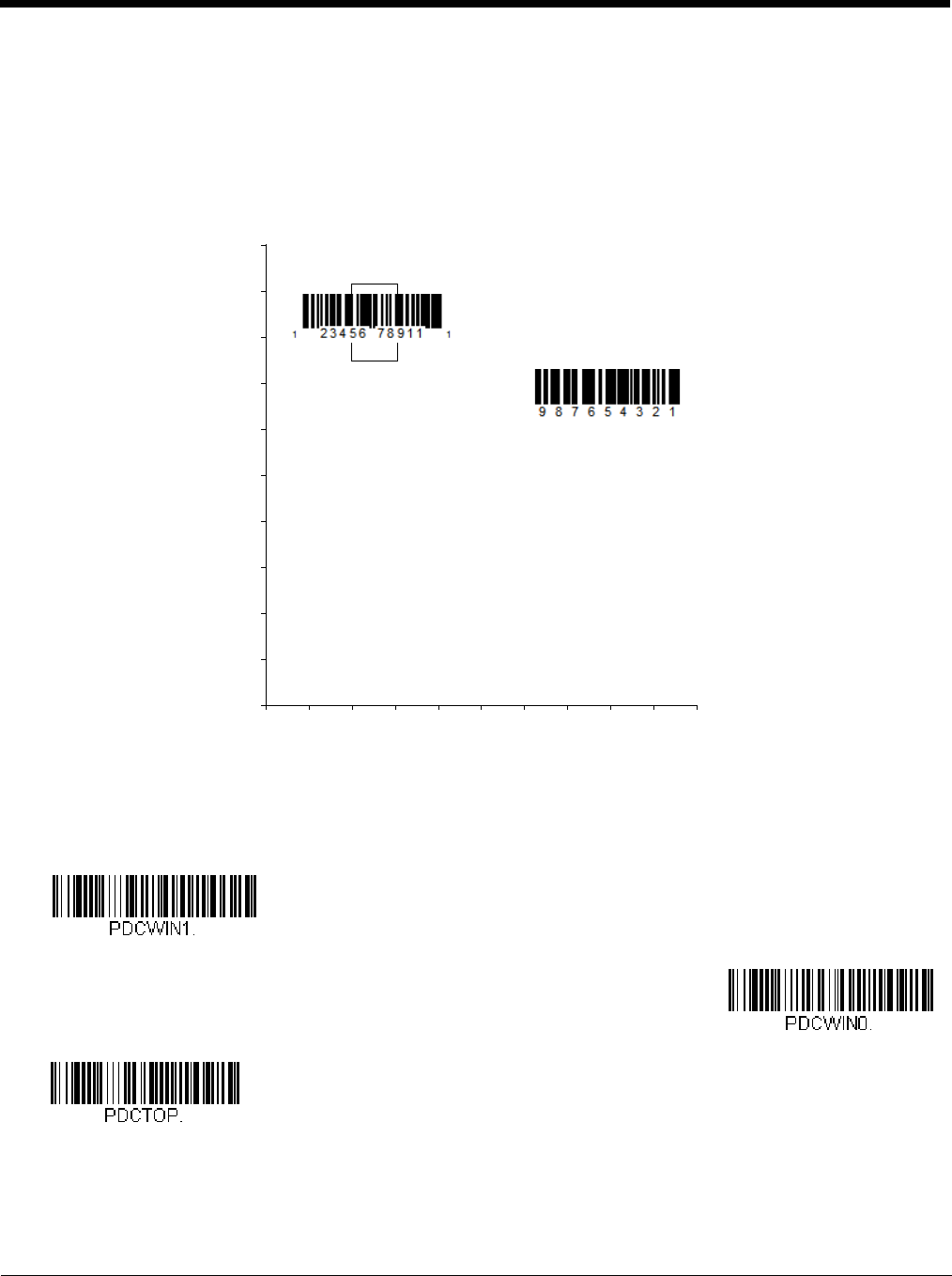
4 - 9
If a bar code is not touched by a predefined window, it will not be decoded or output by the scanner. If Presentation Center-
ing is turned on by scanning Presentation Centering On, the scanner only reads codes that pass through the centering
window you specify using the Top of Presentation Centering Window, Bottom of Presentation Centering Window,
Left, and Right of Presentation Centering Window bar codes.
In the example below, the white box is the centering window. The centering window has been set to 20% left, 30% right,
8% top, and 25% bottom. Since Bar Code 1 passes through the centering window, it will be read. Bar Code 2 does not
pass through the centering window, so it will not be read.
Note: A bar code needs only to be touched by the centering window in order to be read. It does not need to pass completely
through the centering window.
Scan Presentation Centering On, then scan one of the following bar codes to change the top, bottom, left, or right of the
centering window. Then scan the percent you want to shift the centering window using digits on the inside back cover of
this manual. Scan Save. Default Presentation Centering = 40% for Top and Left, 60% for Bottom and Right.
0
Bar Code 1
Bar Code 2
10 20 30 40 50 60 70 80 90 100%
100
90
80
70
60
50
40
30
20
10
0%
Presentation Centering On
* Presentation Centering Off
Top of Presentation Centering
Window
Preliminary draft_1

4 - 10
In-Stand Sensor Mode
Note: The In-Stand Sensor feature only applies to Xenon products.
This feature senses when the scanner is removed from the stand and tells it to begin manual triggering. When Sensor On is
enabled, the scanner defaults to Streaming Presentation Mode when it is in the stand, and to Manual Trigger Mode when it is
removed from the stand. Default = Sensor On.
Note: If you are taking images (see Imaging Commands beginning on page 8-1), you must set the In-Stand Sensor to Off.
You may program a Streaming Presentation Mode (Normal, Enhanced, or Mobile Phone) you wish to use for in-stand scanning,
and a Manual Trigger mode (Normal, Enhanced, or Mobile Phone) you wish to use for out-of-stand scanning. To do this, you
must first scan the preferred Streaming Presentation mode (see below), then scan the Manual Trigger mode (see page 4-6 and
page 4-11) you want to use.
CodeGate®
When CodeGate is On, the trigger is used to allow decoded data to be transmitted to the host system. The scanner remains on,
scanning and decoding bar codes, but the bar code data is not transmitted until the trigger is pressed. When CodeGate is Off,
bar code data is transmitted when it is decoded. Default = CodeGate Off Out-of-Stand.
Bottom of Presentation
Centering Window
Left of
Presentation Centering
Window
Right of Presentation Centering
Window
* Sensor On
Sensor Off
* CodeGate Off
Out-of-Stand
Preliminary draft_1

4 - 11
Streaming Presentation™ Mode
When in Streaming Presentation mode, the scanner’s aimer goes out after a short time, but the scan illumination remains on all
the time to continuously search for bar codes. Two modes are available, Normal and Enhanced. Normal mode offers good
scan speed and the longest working ranges (depth of field). Enhanced mode will give you the highest possible scan speed but
slightly less range than Normal mode. Enhanced mode is best used when you require a very fast scan speed and don’t require
a long working range.
When using Preferred Symbology (page 4-18), a lower priority symbol must be centered on the aiming pattern to be read in
Streaming Presentation Mode.
Note: If you are using a cordless charge base, it must have an external power supply plugged into the aux port for Streaming
Presentation to work properly.
Streaming Presentation In-Stand Programming
This option is available when using In-Stand Sensor Mode, page 4-10. You may program a specific Streaming Presenta-
tion Mode for in-stand scanning, and a Manual Trigger mode for out-of-stand scanning. To do this, you must first scan the
preferred Streaming Presentation mode (Normal, Enhanced, or Mobile Phone), then scan the Manual Trigger mode (Nor-
mal, Enhanced, or Mobile Phone) you want to use.
Mobile Phone Read Mode
When this mode is selected, your scanner is optimized to read bar codes from mobile phone or other LED displays. However,
the speed of scanning printed bar codes may be slightly lower when this mode is enabled. You can enable Mobile Phone Read-
ing for either a hand held device, or for a hands-free (presentation) application.
Note: To turn off Mobil Phone Read Mode, scan a Manual or Serial Trigger Mode bar code (see page 4-6).
CodeGate On
Out-of-Stand
Streaming Presentation Mode
- Normal
Streaming Presentation Mode
- Enhanced
Hand Held Scanning - Mobile
Phone
Streaming Presentation -
Mobile Phone
Preliminary draft_1

4 - 12
Hands Free Time-Out
The Scan Stand and Presentation Modes are referred to as “hands free” modes. If the scanner’s trigger is pulled when using a
hands free mode, the scanner changes to manual trigger mode. You can set the time the scanner should remain in manual trig-
ger mode by setting the Hands Free Time-Out. Once the time-out value is reached, (if there have been no further trigger pulls)
the scanner reverts to the original hands free mode.
Scan the Hands Free Time-Out bar code, then scan the time-out duration (from 0-300,000 milliseconds) from the inside back
cover, and Save. Default = 5,000 ms.
Reread Delay
This sets the time period before the scanner can read the same bar code a second time. Setting a reread delay protects against
accidental rereads of the same bar code. Longer delays are effective in minimizing accidental rereads. Use shorter delays in
applications where repetitive bar code scanning is required. Reread Delay only works when in a Presentation Mode (see page
4-7). Default = Medium.
User-Specified Reread Delay
If you want to set your own length for the reread delay, scan the bar code below, then set the delay (from 0-30,000 millisec-
onds) by scanning digits from the inside back cover, then scanning Save.
Hands Free Time-Out
Short (500 ms)
* Medium (750 ms)
Long (1000 ms)
Extra Long (2000 ms)
User-Specified Reread Delay
Preliminary draft_1
4 - 13
2D Reread Delay
Sometimes 2D bar codes can take longer to read than other bar codes. If you wish to set a separate Reread Delay for 2D
bar codes, scan one of the programming codes that follows. 2D Reread Delay Off indicates that the time set for Reread
Delay is used for both 1D and 2D bar codes. Default = 2D Reread Delay Off.
Character Activation Mode
You may use a character sent from the host to trigger the scanner to begin scanning. When the activation character is received,
the scanner continues scanning until either the Character Activation Timeout (page 4-14), the deactivation character is received
(see Deactivation Character on page 4-15), or a bar code is transmitted. Scan the following On bar code to use character acti-
vation, then use Activation Character (following) to select the character you will send from the host to start scanning. Default =
Off.
* 2D Reread Delay Off
Short (1000ms)
Medium (2000ms)
Long (3000ms)
Extra Long (4000ms)
* Off
On
Preliminary draft_1
4 - 14
Activation Character
This sets the character used to trigger scanning when using Character Activation Mode. On the ASCII Conversion Chart
(Code Page 1252), page A-3, find the hex value that represents the character you want to use to trigger scanning. Scan
the following bar code, then use the Programming Chart to read the alphanumeric combination that represents that ASCII
character. Scan Save to finish. Default = 12 [DC2].
End Character Activation After Good Read
After a bar code is successfully detected and read from the scanner, the illumination can be programmed either to remain
on and scanning, or to turn off. When End Character Activation After Good Read is enabled, the illumination turns off
and stops scanning after a good read. If you scan Do Not End Character Activation After Good Read, the illumination
remains on after a good read. Default = Do Not End Character Activation After Good Read.
Character Activation Timeout
You can set a timeout for the length of time the illumination remains on and attempting to decode bar codes when using
Character Activation Mode. Set the length (in milliseconds) for a timeout by scanning the following bar code, then setting
the timeout (from 1-300,000 milliseconds) by scanning digits from the Programming Chart inside the back cover of this
manual, then scanning Save. Default = 30,000 ms.
Character Deactivation Mode
If you have sent a character from the host to trigger the scanner to begin scanning, you can also send a deactivation character
to stop scanning. Scan the following On bar code to use character deactivation, then use Deactivation Character (following) to
select the character you will send from the host to terminate scanning. Default = Off.
Activation Character
* Do Not End Character
Activation After Good Read
End Character Activation After
Good Read
Character Activation Timeout
* Off
Preliminary draft_1

4 - 15
Deactivation Character
This sets the character used to terminate scanning when using Character Deactivation Mode. On the ASCII Conversion
Chart (Code Page 1252), page A-3, find the hex value that represents the character you want to use to terminate scanning.
Scan the following bar code, then use the Programming Chart inside the back cover of this manual to read the alphanu-
meric combination that represents that ASCII character. Scan Save to finish. Default = 14 [DC4].
Illumination Lights
If you want the illumination lights on while reading a bar code, scan the Lights On bar code, below. However, if you want to turn
just the lights off, scan the Lights Off bar code. Default = Lights On.
Note: This setting does not affect the aimer light. The aiming light can be set using Aimer Mode (page 4-16).
Aimer Delay
The aimer delay allows a delay time for the operator to aim the scanner before the picture is taken. Use these codes to set the
time between when the trigger is pulled and when the picture is taken. During the delay time, the aiming light will appear, but
the LEDs won’t turn on until the delay time is over. Default = Off.
On
Deactivation Character
* Lights On
Lights Off
200 milliseconds
400 milliseconds
* Off (no delay)
Preliminary draft_1

4 - 16
User-Specified Aimer Delay
If you want to set your own length for the duration of the delay, scan the bar code below, then set the time-out by scanning
digits (0 - 4,000 ms) from the Programming Chart inside the back cover of this manual, then scan Save.
Aimer Mode
This feature allows you to turn the aimer on and off. When the Interlaced bar code is scanned, the aimer is interlaced with the
illumination LEDs. Default = Interlaced.
Centering
Use Centering to narrow the scanner’s field of view to make sure that when the scanner is hand-held, it reads only those bar
codes intended by the user. For instance, if multiple codes are placed closely together, centering will insure that only the
desired codes are read. (Centering can be used in conjunction with Aimer Delay, page 4-15, for the most error-free operation
in applications where multiple codes are spaced closely together. Using the Aimer Delay and Centering features, the scanner
can emulate the operation of older systems, such as linear laser bar code scanners.)
Note: To adjust centering when the scanner is in the stand, see Presentation Centering (page 4-8).
If a bar code is not touched by a predefined window, it will not be decoded or output by the scanner. If centering is turned on by
scanning Centering On, the scanner only reads codes that pass through the centering window you specify using the Top of
Centering Window, Bottom of Centering Window, Left, and Right of Centering Window bar codes.
Delay Duration
Off
* Interlaced
Preliminary draft_1
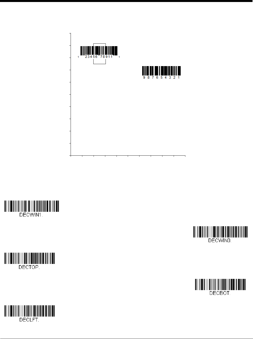
4 - 17
In the example below, the white box is the centering window. The centering window has been set to 20% left, 30% right, 8% top,
and 25% bottom. Since Bar Code 1 passes through the centering window, it will be read. Bar Code 2 does not pass through
the centering window, so it will not be read.
Note: A bar code needs only to be touched by the centering window in order to be read. It does not need to pass completely
through the centering window.
Scan Centering On, then scan one of the following bar codes to change the top, bottom, left, or right of the centering window.
Then scan the percent you want to shift the centering window using digits on the inside back cover of this manual. Scan Save.
Default Centering = 40% for Top and Left, 60% for Bottom and Right.
0
Bar Code 1
Bar Code 2
10 20 30 40 50 60 70 80 90 100%
100
90
80
70
60
50
40
30
20
10
0%
Centering On
* Centering Off
Top of Centering Window
Bottom of Centering Window
Left of Centering Window
Preliminary draft_1

4 - 18
Preferred Symbology
The scanner can be programmed to specify one symbology as a higher priority over other symbologies in situations where both
bar code symbologies appear on the same label, but the lower priority symbology cannot be disabled.
For example, you may be using the scanner in a retail setting to read U.P.C. symbols, but have occasional need to read a code
on a drivers license. Since some licenses have a Code 39 symbol as well as the PDF417 symbol, you can use Preferred Sym-
bology to specify that the PDF417 symbol be read instead of the Code 39.
Preferred Symbology classifies each symbology as high priority, low priority, or as an unspecified type. When a low priority
symbology is presented, the scanner ignores it for a set period of time (see Preferred Symbology Time-out on page 4-19) while
it searches for the high priority symbology. If a high priority symbology is located during this period, then that data is read imme-
diately.
If the time-out period expires before a high priority symbology is read, the scanner will read any bar code in its view (low priority
or unspecified). If there is no bar code in the scanner’s view after the time-out period expires, then no data is reported.
Note: A low priority symbol must be centered on the aiming pattern to be read.
Scan a bar code below to enable or disable Preferred Symbology. Default = Preferred Symbology Off.
High Priority Symbology
To specify the high priority symbology, scan the High Priority Symbology bar code below. On the Symbology Charts on
page A-1, find the symbology you want to set as high priority. Locate the Hex value for that symbology and scan the 2 digit
hex value from the Programming Chart (inside back cover). Scan Save to save your selection. Default = None
Low Priority Symbology
To specify the low priority symbology, scan the Low Priority Symbology bar code below. On the Symbology Charts on page
A-1, find the symbology you want to set as low priority. Locate the Hex value for that symbology and scan the 2 digit hex
value from the Programming Chart (inside back cover).
Right of Centering Window
Preferred Symbology On
* Preferred Symbology Off
High Priority Symbology
Preliminary draft_1

4 - 19
If you want to set additional low priority symbologies, scan FF, then scan the 2 digit hex value from the Programming Chart
for the next symbology. You can program up to 5 low priority symbologies. Scan Save to save your selection. Default =
None.
Preferred Symbology Time-out
Once you have enabled Preferred Symbology and entered the high and low priority symbologies, you must set the time-out
period. This is the period of time the scanner will search for a high priority bar code after a low priority bar code has been
encountered. Scan the bar code below, then set the delay (from 1-3,000 milliseconds) by scanning digits from the inside
back cover, then scanning Save. Default = 500 ms.
Preferred Symbology Default
Scan the bar code below to set all Preferred Symbology entries to their default values.
Output Sequence Overview
Output Sequence Editor
This programming selection allows you to program the scanner to output data (when scanning more than one symbol) in
whatever order your application requires, regardless of the order in which the bar codes are scanned. Reading the Default
Sequence symbol programs the scanner to the Universal values, shown below. These are the defaults. Be certain you
want to delete or clear all formats before you read the Default Sequence symbol.
Note: To make Output Sequence Editor selections, you’ll need to know the code I.D., code length, and character match(es)
your application requires. Use the Alphanumeric symbols (inside back cover) to read these options. You must hold
the trigger while reading each bar code in the sequence.
To Add an Output Sequence
1. Scan the Enter Sequence symbol (see Require Output Sequence, page 4-21).
2. Code I.D.
On the Symbology Charts on page A-1, find the symbology to which you want to apply the output sequence format.
Locate the Hex value for that symbology and scan the 2 digit hex value from the Programming Chart (inside back
cover).
3. Length
Specify what length (up to 9999 characters) of data output will be acceptable for this symbology. Scan the four digit
data length from the Programming Chart. (Note: 50 characters is entered as 0050. 9999 is a universal number,
indicating all lengths.) When calculating the length, you must count any programmed prefixes, suffixes, or formatted
characters as part of the length (unless using 9999).
4. Character Match Sequences
On the ASCII Conversion Chart (Code Page 1252), page A-3, find the Hex value that represents the character(s) you
want to match. Use the Programming Chart to read the alphanumeric combination that represents the ASCII
characters. (99 is the Universal number, indicating all characters.)
Low Priority Symbology
Preferred Symbology Time-out
Preferred Symbology Default
Preliminary draft_1

4 - 20
5. End Output Sequence Editor
Scan F F to enter an Output Sequence for an additional symbology, or Save to save your entries.
Other Programming Selections
•Discard
This exits without saving any Output Sequence changes.
Output Sequence Example
In this example, you are scanning Code 93, Code 128, and Code 39 bar codes, but you want the scanner to output Code 39
1st, Code 128 2nd, and Code 93 3rd, as shown below.
Note: Code 93 must be enabled to use this example.
You would set up the sequence editor with the following command line:
SEQBLK62999941FF6A999942FF69999943FF
The breakdown of the command line is shown below:
SEQBLKsequence editor start command
62 code identifier for Code 39
9999 code length that must match for Code 39, 9999 = all lengths
41 start character match for Code 39, 41h = “A”
FF termination string for first code
6A code identifier for Code 128
9999 code length that must match for Code 128, 9999 = all lengths
42 start character match for Code 128, 42h = “B”
FF termination string for second code
69 code identifier for Code 93
9999 code length that must match for Code 93, 9999 = all lengths
43 start character match for Code 93, 43h = “C”
FF termination string for third code
To program the previous example using specific lengths, you would have to count any programmed prefixes, suffixes, or for-
matted characters as part of the length. If you use the example on page 4-20, but assume a <CR> suffix and specific code
lengths, you would use the following command line:
SEQBLK62001241FF6A001342FF69001243FF
The breakdown of the command line is shown below:
SEQBLKsequence editor start command
62 code identifier for Code 39
0012 A - Code 39 sample length (11) plus CR suffix (1) = 12
A - Code 39
B - Code 128
C - Code 93
Preliminary draft_1

4 - 21
41 start character match for Code 39, 41h = “A”
FF termination string for first code
6A code identifier for Code 128
0013 B - Code 128 sample length (12) plus CR suffix (1) = 13
42 start character match for Code 128, 42h = “B”
FF termination string for second code
69 code identifier for Code 93
0012 C - Code 93 sample length (11) plus CR suffix (1) = 12
43 start character match for Code 93, 43h = “C”
FF termination string for third code
Output Sequence Editor
Partial Sequence
If an output sequence operation is terminated before all your output sequence criteria are met, the bar code data acquired
to that point is a “partial sequence.”
Scan Discard Partial Sequence to discard partial sequences when the output sequence operation is terminated before
completion. Scan Transmit Partial Sequence to transmit partial sequences. (Any fields in the sequence where no data
match occurred will be skipped in the output.)
Require Output Sequence
When an output sequence is Required, all output data must conform to an edited sequence or the scanner will not transmit
the output data to the host device. When it’s On/Not Required, the scanner will attempt to get the output data to conform
to an edited sequence but, if it cannot, the scanner transmits all output data to the host device as is.
Enter Sequence
Default Sequence
Transmit Partial Sequence
* Discard Partial Sequence
Preliminary draft_1

4 - 22
When the output sequence is Off, the bar code data is output to the host as the scanner decodes it. Default = Off.
Note: This selection is unavailable when the Multiple Symbols Selection is turned on.
Multiple Symbols
When this programming selection is turned On, it allows you to read multiple symbols with a single pull of the scanner’s trigger.
If you press and hold the trigger, aiming the scanner at a series of symbols, it reads unique symbols once, beeping (if turned on)
for each read. If using a Granit scanner, the scanner also vibrates. The scanner attempts to find and decode new symbols as
long as the trigger is pulled. When this programming selection is turned Off, the scanner will only read the symbol closest to the
aiming beam. Default = Off.
No Read
With No Read turned On, the scanner notifies you if a code cannot be read. If using an EZConfig-Scanning Tool Scan Data
Window (see page 10-3), an “NR” appears when a code cannot be read. If No Read is turned Off, the “NR” will not appear.
Default = Off.
If you want a different notation than “NR,” for example, “Error,” or “Bad Code,” you can edit the output message (see Data
Formatting beginning on page 6-1). The hex code for the No Read symbol is 9C.
Required
On/Not Required
*Off
On
* Off
On
* Off
Preliminary draft_1

4 - 23
Video Reverse
Video Reverse is used to allow the scanner to read bar codes that are inverted. The Video Reverse Off bar code below is an
example of this type of bar code. Scan Video Reverse Only to read only inverted bar codes. Scan Video Reverse and Stan-
dard Bar Codes to read both types of codes.
Note: After scanning Video Reverse Only, menu bar codes cannot be read. You must scan Video Reverse Off or Video
Reverse and Standard Bar Codes in order to read menu bar codes.
Note: Images downloaded from the unit are not reversed. This is a setting for decoding only.
Working Orientation
Some bar codes are direction-sensitive. For example, KIX codes and OCR can misread when scanned sideways or upside
down. Use the working orientation settings if your direction-sensitive codes will not usually be presented upright to the scanner.
Default = Upright.
Video Reverse Only
Video Reverse and Standard Bar
Codes
* Video Reverse Off
Upright:
Vertical, Top to Bottom:
(Rotate CW 90°)
Upside Down:
Vertical, Bottom to Top:
(Rotate CCW 90°)
Preliminary draft_1

4 - 24
* Upright
Vertical, Bottom to Top
Upside Down
Vertical, Top to Bottom
Preliminary draft_1

5 - 1
5
Data Editing
Prefix/Suffix Overview
When a bar code is scanned, additional information is sent to the host computer along with the bar code data. This group of bar
code data and additional, user-defined data is called a “message string.” The selections in this section are used to build the
user-defined data into the message string.
Prefix and Suffix characters are data characters that can be sent before and after scanned data. You can specify if they should
be sent with all symbologies, or only with specific symbologies. The following illustration shows the breakdown of a message
string:
Points to Keep In Mind
• It is not necessary to build a message string. The selections in this chapter are only used if you wish to alter the default
settings. Default prefix = None. Default suffix = None.
• A prefix or suffix may be added or cleared from one symbology or all symbologies.
• You can add any prefix or suffix from the ASCII Conversion Chart (Code Page 1252), beginning on page A-3, plus Code
I.D. and AIM I.D.
• You can string together several entries for several symbologies at one time.
• Enter prefixes and suffixes in the order in which you want them to appear on the output.
• When setting up for specific symbologies (as opposed to all symbologies), the specific symbology ID value counts as an
added prefix or suffix character.
• The maximum size of a prefix or suffix configuration is 200 characters, which includes header information.
To Add a Prefix or Suffix:
Step 1. Scan the Add Prefix or Add Suffix symbol (page 5-2).
Step 2. Determine the 2 digit Hex value from the Symbology Chart (included in the Symbology Charts, beginning on page
A-1) for the symbology to which you want to apply the prefix or suffix. For example, for Code 128, Code ID is “j” and
Hex ID is “6A”.
Step 3. Scan the 2 hex digits from the Programming Chart inside the back cover of this manual or scan 9, 9 for all
symbologies.
Step 4. Determine the hex value from the ASCII Conversion Chart (Code Page 1252), beginning on page A-3, for the prefix
or suffix you wish to enter.
Step 5. Scan the 2 digit hex value from the Programming Chart inside the back cover of this manual.
Step 6. Repeat Steps 4 and 5 for every prefix or suffix character.
Step 7. To add the Code I.D., scan 5, C, 8, 0.
To add AIM I.D., scan 5, C, 8, 1.
To add a backslash (\), scan 5, C, 5, C.
Note: To add a backslash (\) as in Step 7, you must scan 5C twice – once to create the leading backslash and then to create
the backslash itself.
Step 8. Scan Save to exit and save, or scan Discard to exit without saving.
Repeat Steps 1-6 to add a prefix or suffix for another symbology.
Prefix Scanned Data Suffix
1-11
alpha numeric &
control characters
variable length1-11
alpha numeric &
control characters
Preliminary draft_1

5 - 2
Example: Add a Tab Suffix to All Symbologies
Step 1. Scan Add Suffix.
Step 2. Scan 9, 9 from the Programming Chart inside the back cover of this manual to apply this suffix to all symbologies.
Step 3. Scan 0, 9 from the Programming Chart inside the back cover of this manual. This corresponds with the hex value
for a horizontal tab, shown in the ASCII Conversion Chart (Code Page 1252), beginning on page A-3.
Scan Save, or scan Discard to exit without saving.
To Clear One or All Prefixes or Suffixes
You can clear a single prefix or suffix, or clear all prefixes/suffixes for a symbology. If you have been entering prefixes and
suffixes for single symbologies, you can use Clear One Prefix (Suffix) to delete a specific character from a symbology.
When you Clear All Prefixes (Suffixes), all the prefixes or suffixes for a symbology are deleted.
Step 1. Scan the Clear One Prefix or Clear One Suffix symbol.
Step 2. Determine the 2 digit Hex value from the Symbology Chart (included in the Symbology Charts, beginning on page
A-1) for the symbology from which you want to clear the prefix or suffix.
Step 3. Scan the 2 digit hex value from the Programming Chart inside the back cover of this manual or scan 9, 9 for all
symbologies.
Your change is automatically saved.
To Add a Carriage Return Suffix to All Symbologies
Scan the following bar code if you wish to add a carriage return suffix to all symbologies at once. This action first clears all
current suffixes, then programs a carriage return suffix for all symbologies.
Prefix Selections
Suffix Selections
Add CR Suffix
All Symbologies
Add Prefix
Clear One Prefix
Clear All Prefixes
Add Suffix
Preliminary draft_1