Honeywell 51306343 51306343 User Manual Ext Temp Pro Install guide
Honeywell International Inc. 51306343 Ext Temp Pro Install guide
UserManual.wiki
>
Honeywell
>
51306343 User Manual
>
Ext Temp Pro Install guide
Contents
1.
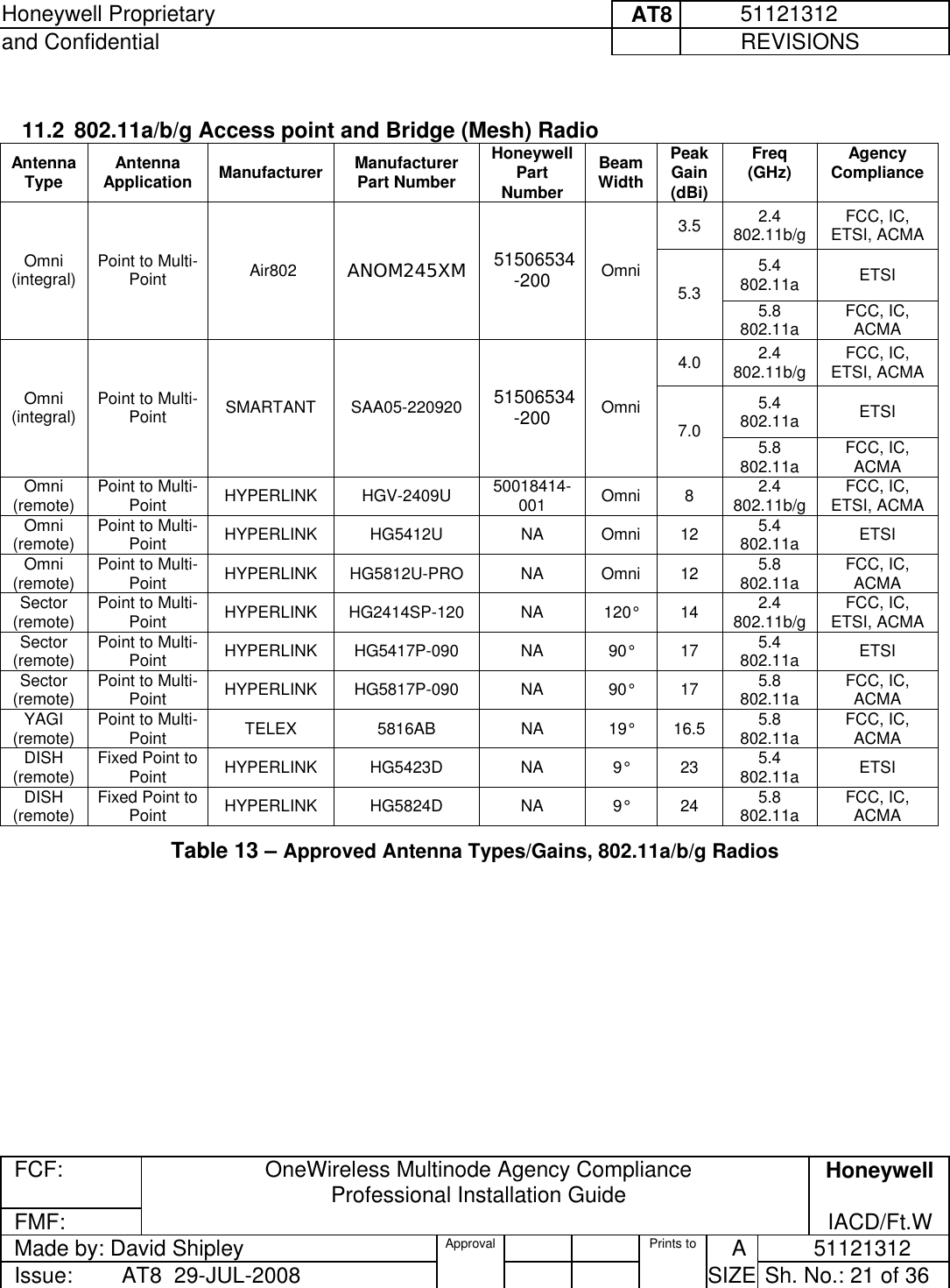
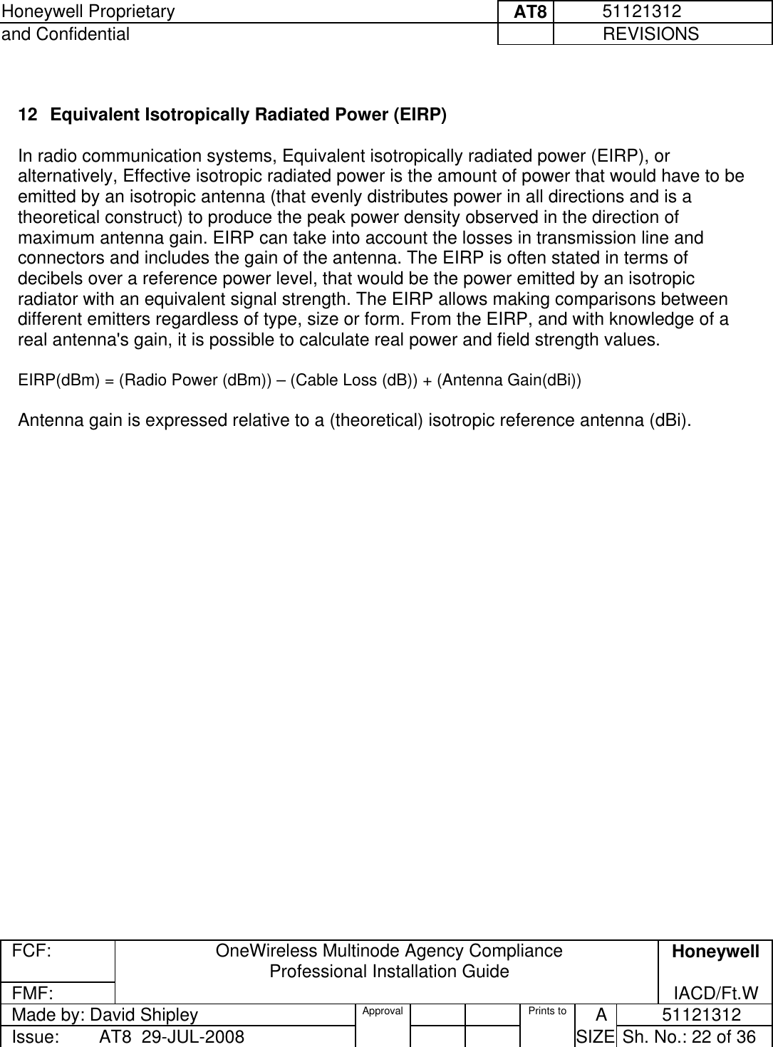
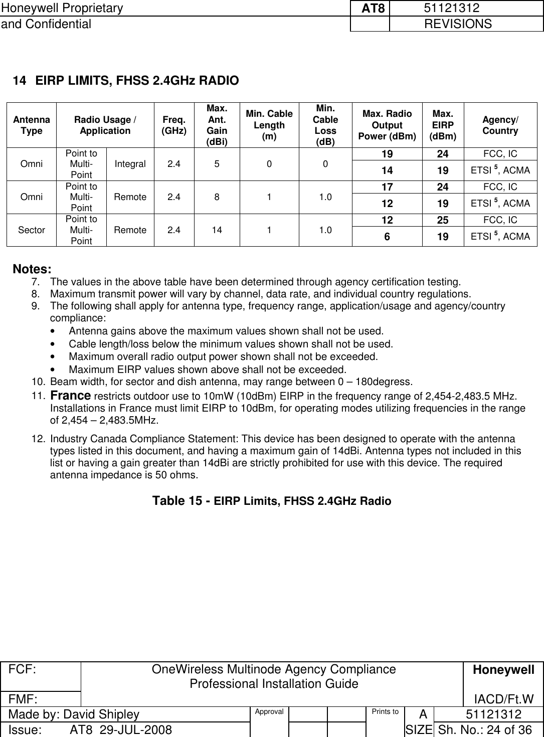
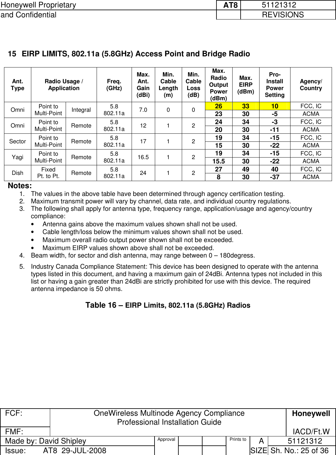
Ext Temp Pro Install guide
2.
Users Guide
3.
Standard Temp Pro Install Guide
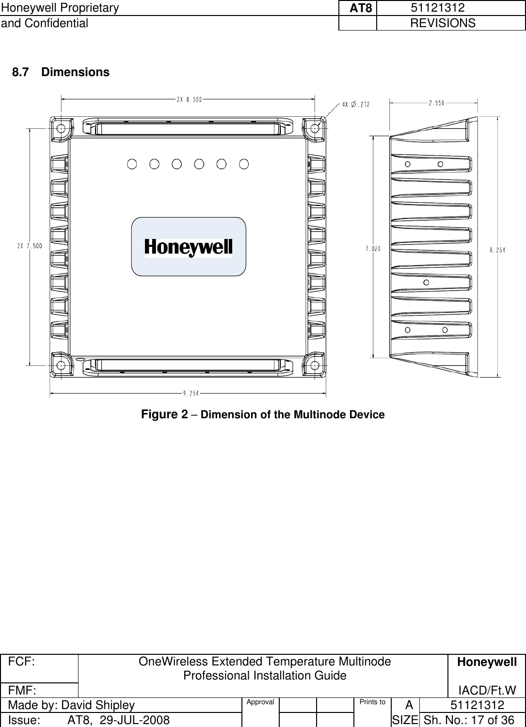
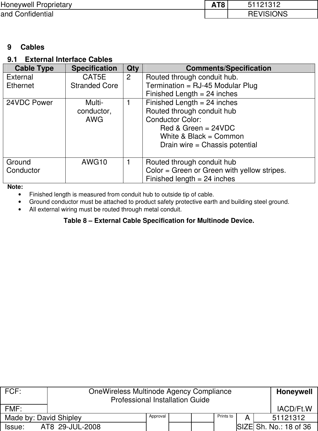
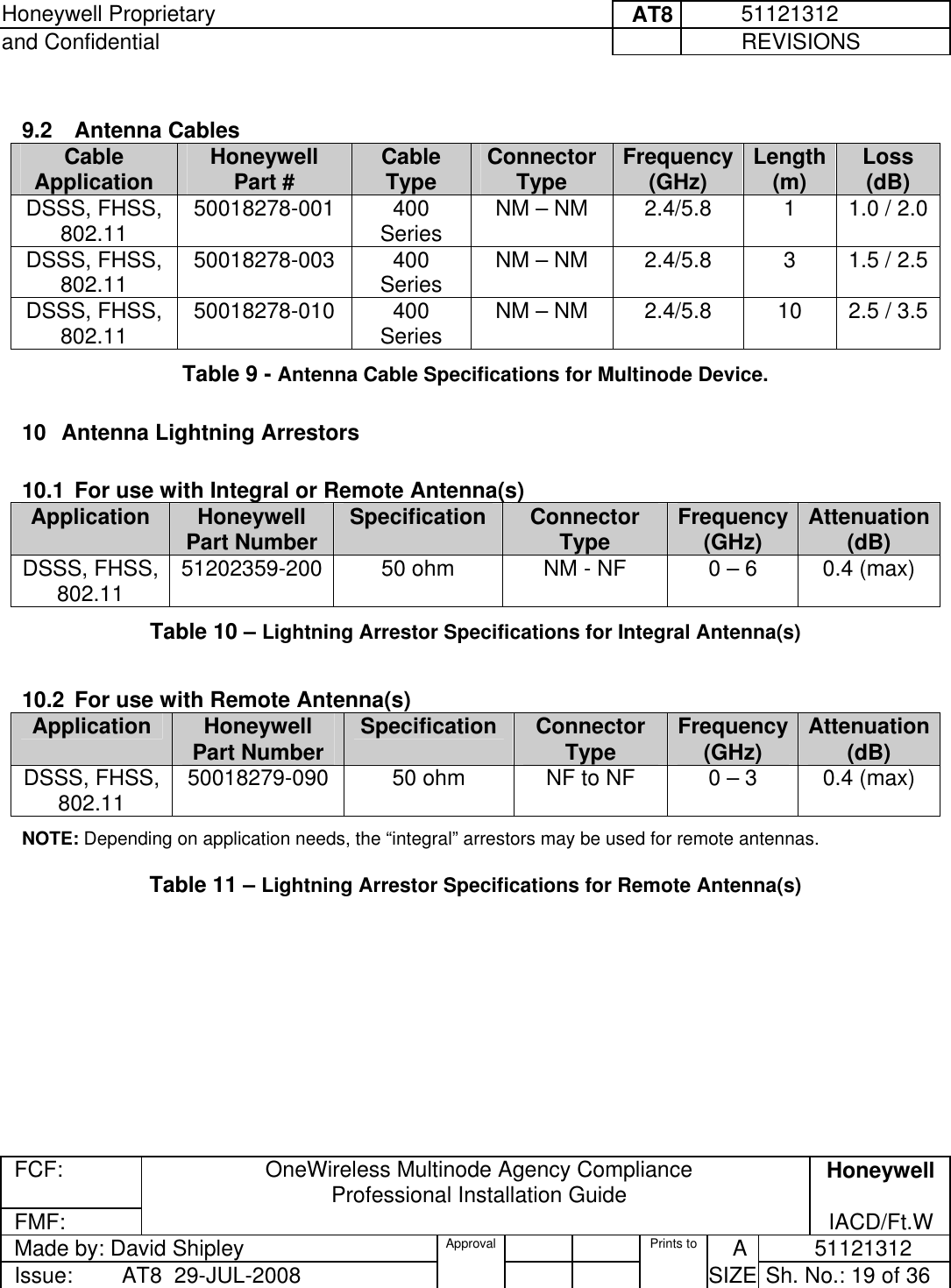
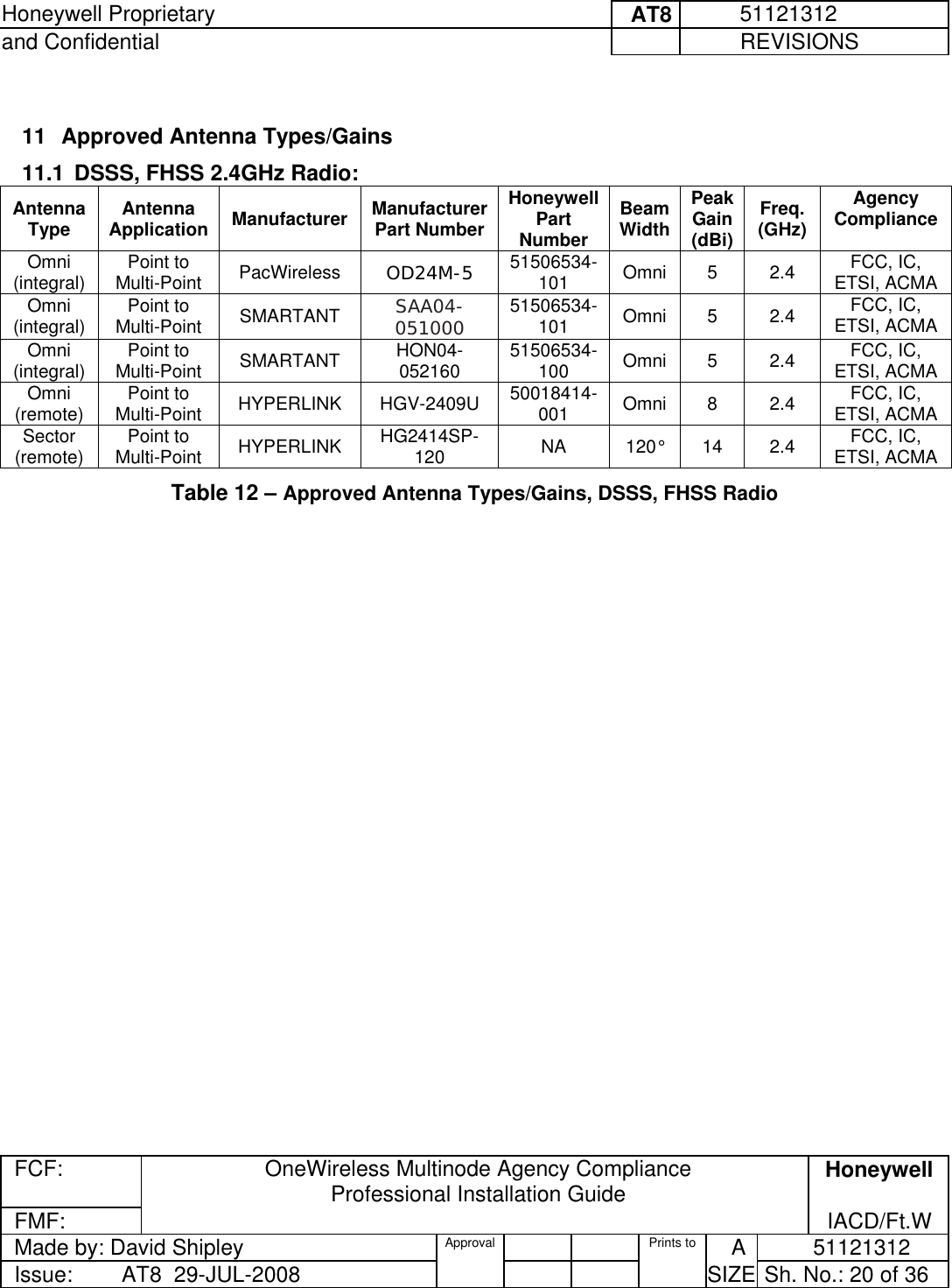
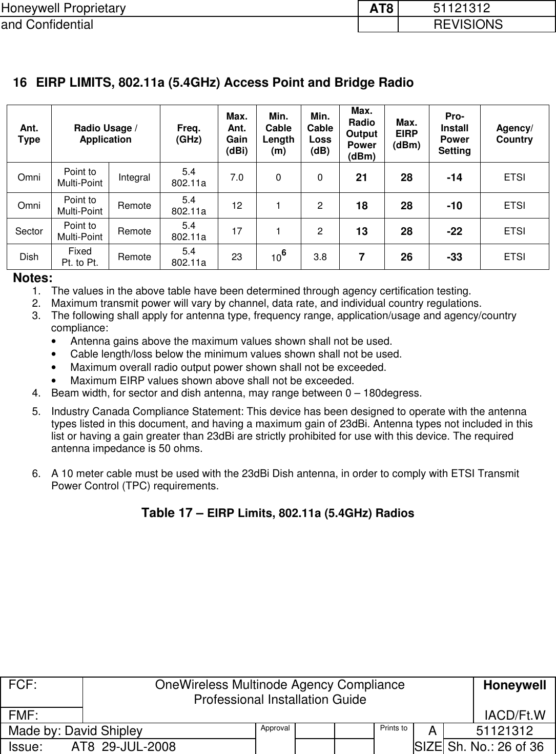
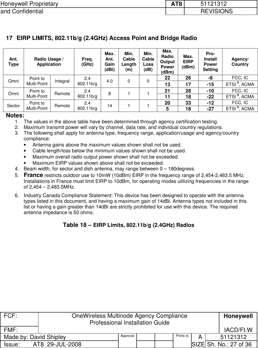
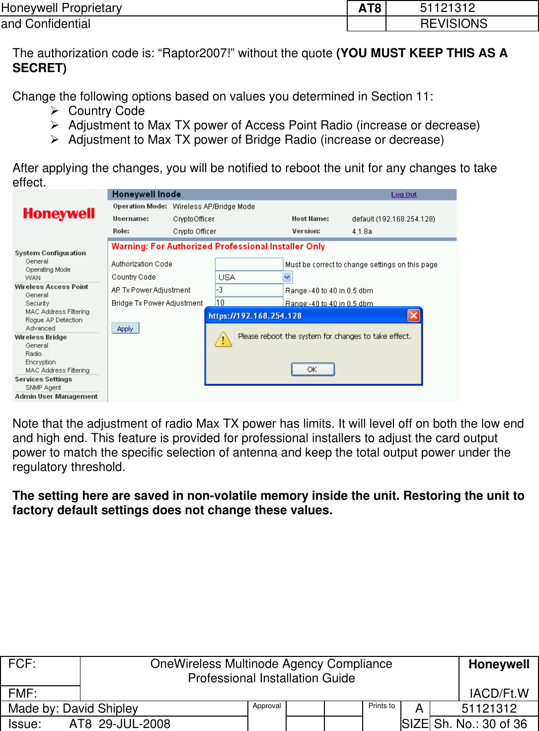
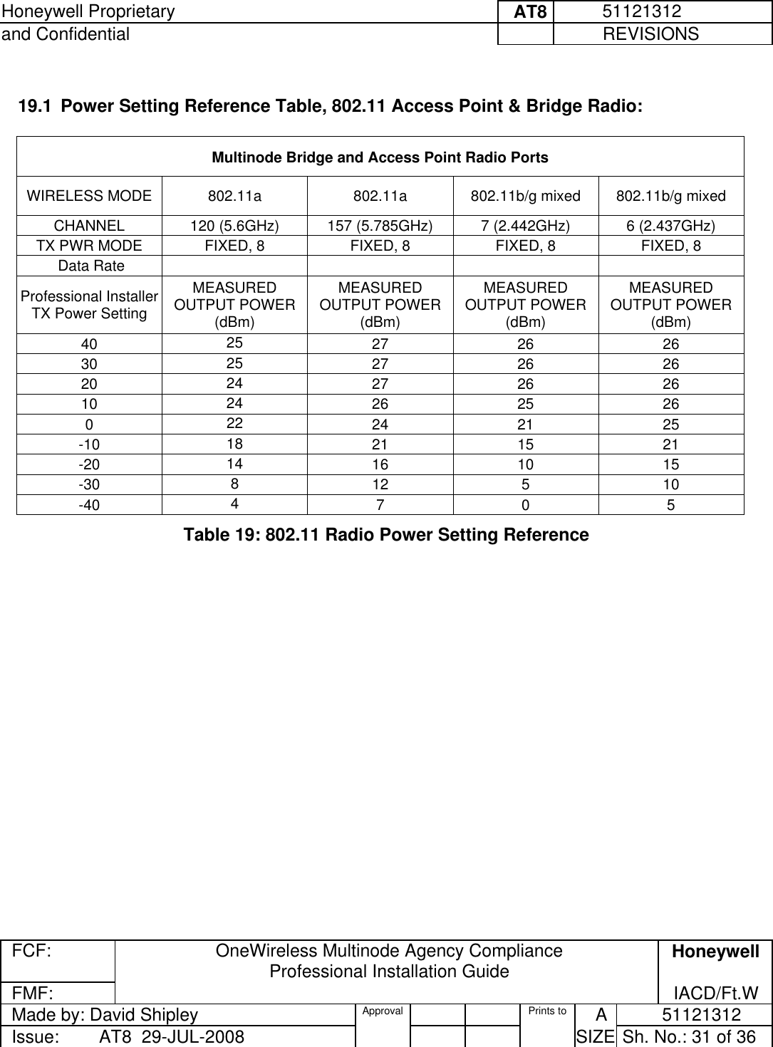
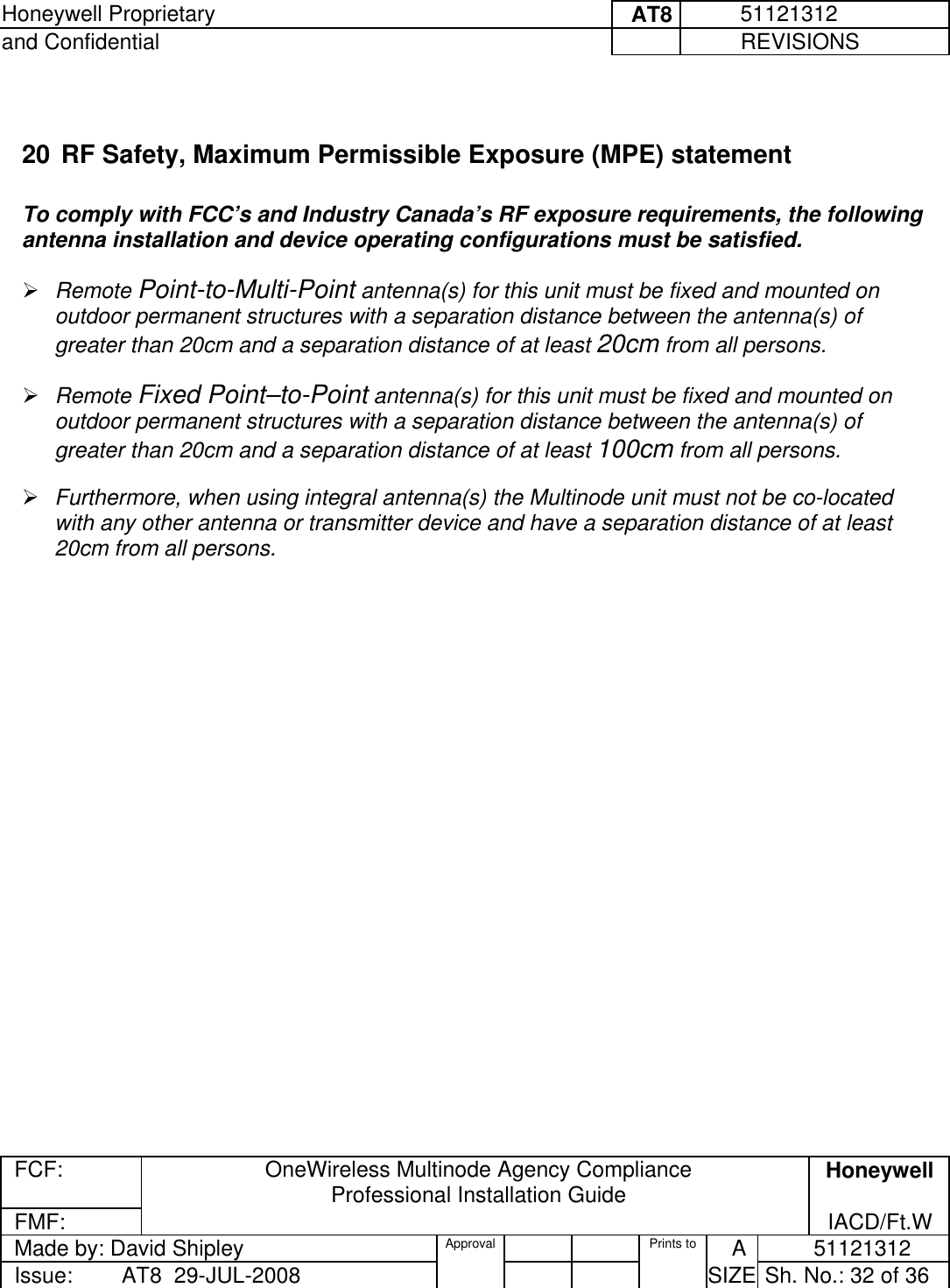
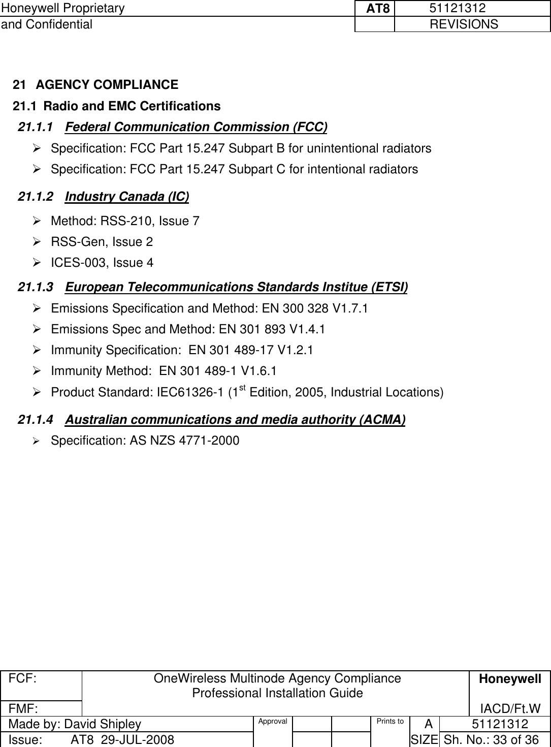
Ext Temp Pro Install guide
Navigation menu
Upload a User Manual
Namespaces
Wiki Guide
HTML
PDF
Info
Views
User Manual
Discussion / Help
Navigation