Honeywell 51306799 LOW COST ISA 100 RADIO MODULE(51306799-001) User Manual KEYBEE
Honeywell International Inc. LOW COST ISA 100 RADIO MODULE(51306799-001) KEYBEE
UserManual.wiki
>
Honeywell
>
51306799 User Manual
>
User Manual
Contents
1.
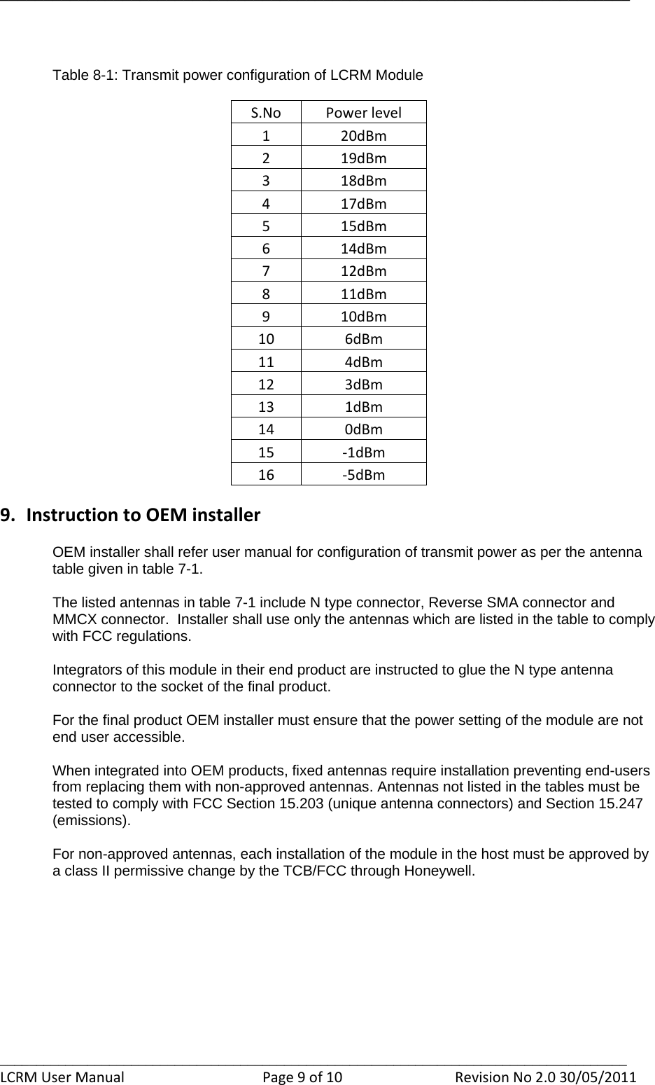
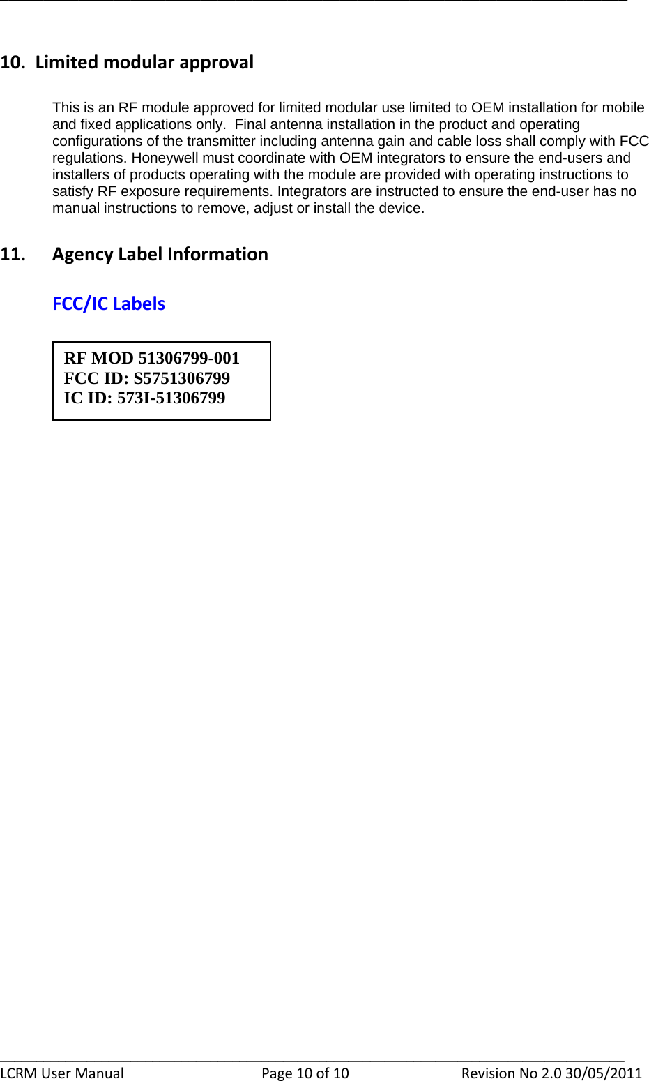
User Manual
2.
Manual
3.
User Guide
4.
Installation Guide
User Manual
Navigation menu
Upload a User Manual
Namespaces
Wiki Guide
HTML
PDF
Info
Views
User Manual
Discussion / Help
Navigation