Honeywell 51306799 Wireless Field Interface User Manual WFI IOM
Honeywell International Inc. Wireless Field Interface WFI IOM
UserManual.wiki
>
Honeywell
>
51306799 User Manual
>
Installation Guide
Contents
1.
User Manual
2.
Manual
3.
User Guide
4.
Installation Guide
Installation Guide
Navigation menu
Upload a User Manual
Namespaces
Wiki Guide
HTML
PDF
Info
Views
User Manual
Discussion / Help
Navigation
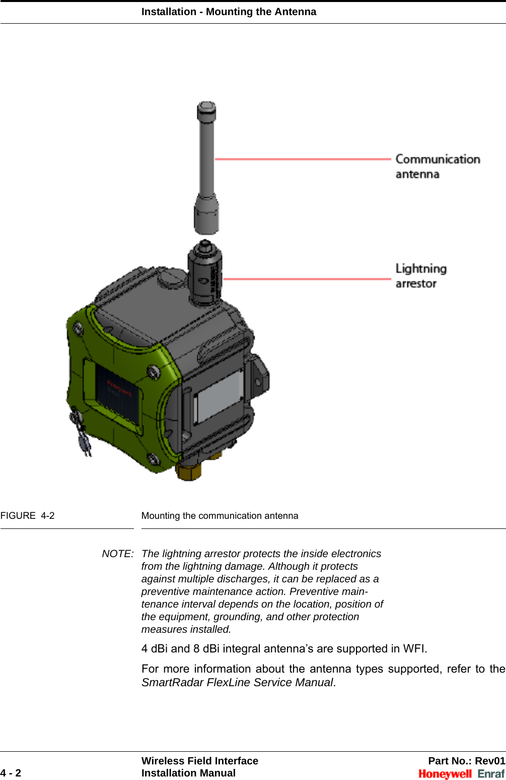
![Safety - Safety Instructions for the WFIWireless Field Interface Part No.: Rev012 - 6 Installation ManualImproper installation of cable glands, threaded adaptors, stopping plugs, and their interface invalidates the Ex approval of the WFI device.Accurate dimensions of the flameproof joints must be used. Contact Honeywell Enraf for information regarding the dimensions of the flameproof joints.2.2.3.2 Accordance to Regulations2.2.3.3 Explosion Safety2.2.3.4 Compliance to FCCThis device complies with Part 15 of the FCC Rules. The WFI device does not cause any harmful interference and accepts any interference received.2.2.3.5 Low-Voltage DirectiveThe device is suitable for 2006/95/EC.The applicable standard value is IEC 61010-1 (3rd Edition).2.2.3.6 Reference of Applicable StandardsApproval Certificate no. Type of protection identificationATEX Approval pending II 2 GEx d [ia] IIB T6 GbTa = -40 °C ... +65 °C(-40 °F ... +149 °F)IECEx Approval pending Zone 1FM Approval pending Class I, Division 1 group C, D T6CSA Approval pendingClass I, Division 1 group C, D T6Zone 1 Ex d [ia] IIB T6Standard DescriptionATEX 95 Applicable for manufacturers of equipment used in places where explosion danger may exist.IECEx The IECEx System is an International Conformity System where a Mark of Conformity is granted by approved IECEx certifiers (ExCBs) located in IECEx participating countries for equipment that is covered by an IECEx Certificate of Confor-mity and hence has been tested and manufactured under systems that are under ongoing surveillance by ExCBs.FM Factory Mutual Approvals DivisionThe Factory Mutual Approvals Division determines the safety and reliability of equipment, materials, or services utilized in hazardous locations in the United States and elsewhere.CSA Canadian Standards AssociationThe standards generated by CSA are the cornerstone for determining a product's eligibility for certification in hazardous locations in Canada.](https://usermanual.wiki/Honeywell/51306799.Installation-Guide/User-Guide-2226520-Page-10.png)