Honeywell 51306799 Wireless Field Interface User Manual WFI IOM
Honeywell International Inc. Wireless Field Interface WFI IOM
Contents
- 1. User Manual
- 2. Manual
- 3. User Guide
- 4. Installation Guide
Installation Guide

Table of Contents
Part No.: Rev01 Wireless Field Interface
Installation & Operation Manual i
CHAPTER 1 GENERAL. . . . . . . . . . . . . . . . . . . . . . . . . . . . . . . . . 1-1
1.1 Product Introduction. . . . . . . . . . . . . . . . . . . . . . . . . . . 1-1
1.2 Target Audience for this Manual . . . . . . . . . . . . . . . . . 1-2
CHAPTER 2 SAFETY . . . . . . . . . . . . . . . . . . . . . . . . . . . . . . . . . . 2-1
2.1 Safety Conventions. . . . . . . . . . . . . . . . . . . . . . . . . . . . 2-1
2.1.1 Warnings . . . . . . . . . . . . . . . . . . . . . . . . . . . . . . . . . . . . . . . . . .2-1
2.1.2 Cautions . . . . . . . . . . . . . . . . . . . . . . . . . . . . . . . . . . . . . . . . . .2-1
2.2 Safety Instructions for the WFI . . . . . . . . . . . . . . . . . . 2-2
2.2.1 General . . . . . . . . . . . . . . . . . . . . . . . . . . . . . . . . . . . . . . . . . . .2-2
2.2.1.1 EC declaration of conformity (for EU) . . . . . . . . . . . . . . . . . . . .2-3
2.2.1.2 Control Drawings for FM and CSA . . . . . . . . . . . . . . . . . . . . . .2-3
2.2.1.3 Users. . . . . . . . . . . . . . . . . . . . . . . . . . . . . . . . . . . . . . . . . . . . .2-3
2.2.1.4 Additional information . . . . . . . . . . . . . . . . . . . . . . . . . . . . . . . .2-4
2.2.1.5 Environmental Conditions . . . . . . . . . . . . . . . . . . . . . . . . . . . . .2-4
2.2.2 Personal Safety. . . . . . . . . . . . . . . . . . . . . . . . . . . . . . . . . . . . .2-4
2.2.2.1 General . . . . . . . . . . . . . . . . . . . . . . . . . . . . . . . . . . . . . . . . . . .2-4
2.2.2.1.1 Repairs and Maintenance. . . . . . . . . . . . . . . . . . . . . . . . . . . . . . . . . .2-4
2.2.2.1.2 Opening of the Device . . . . . . . . . . . . . . . . . . . . . . . . . . . . . . . . . . . .2-4
2.2.2.1.3 Tools . . . . . . . . . . . . . . . . . . . . . . . . . . . . . . . . . . . . . . . . . . . . . . . . . .2-5
2.2.2.1.4 Working Environment . . . . . . . . . . . . . . . . . . . . . . . . . . . . . . . . . . . . .2-5
2.2.2.1.5 Required Skills . . . . . . . . . . . . . . . . . . . . . . . . . . . . . . . . . . . . . . . . . .2-5
2.2.2.2 Commissioning . . . . . . . . . . . . . . . . . . . . . . . . . . . . . . . . . . . . .2-5
2.2.2.3 Maintenance and troubleshooting . . . . . . . . . . . . . . . . . . . . . . .2-5
2.2.2.4 Grounding . . . . . . . . . . . . . . . . . . . . . . . . . . . . . . . . . . . . . . . . .2-5
2.2.3 Electrical . . . . . . . . . . . . . . . . . . . . . . . . . . . . . . . . . . . . . . . . . .2-5
2.2.3.1 Safety Standards. . . . . . . . . . . . . . . . . . . . . . . . . . . . . . . . . . . .2-5
2.2.3.2 Accordance to Regulations . . . . . . . . . . . . . . . . . . . . . . . . . . . .2-6
2.2.3.3 Explosion Safety . . . . . . . . . . . . . . . . . . . . . . . . . . . . . . . . . . . .2-6
2.2.3.4 Compliance to FCC. . . . . . . . . . . . . . . . . . . . . . . . . . . . . . . . . .2-6
2.2.3.5 Low-Voltage Directive . . . . . . . . . . . . . . . . . . . . . . . . . . . . . . . .2-6
2.2.3.6 Reference of Applicable Standards. . . . . . . . . . . . . . . . . . . . . .2-6
2.2.3.7 WFI Labels . . . . . . . . . . . . . . . . . . . . . . . . . . . . . . . . . . . . . . . .2-7
2.3 Liability. . . . . . . . . . . . . . . . . . . . . . . . . . . . . . . . . . . . . . 2-8
CHAPTER 3 SYSTEM DESCRIPTION . . . . . . . . . . . . . . . . . . . . . 3-1
3.1 Introduction . . . . . . . . . . . . . . . . . . . . . . . . . . . . . . . . . . 3-1
3.2 System Architecture . . . . . . . . . . . . . . . . . . . . . . . . . . . 3-1

Table of Contents
Wireless Field Interface Part No.: Rev01
ii Installation Manual
3.3 FlexConn Modules. . . . . . . . . . . . . . . . . . . . . . . . . . . . . 3-1
3.3.1 General . . . . . . . . . . . . . . . . . . . . . . . . . . . . . . . . . . . . . . . . . . .3-1
3.3.2 Grounding Concept. . . . . . . . . . . . . . . . . . . . . . . . . . . . . . . . . .3-3
3.3.3 Enclosure Earth Details. . . . . . . . . . . . . . . . . . . . . . . . . . . . . . .3-4
3.3.4 Field Wiring . . . . . . . . . . . . . . . . . . . . . . . . . . . . . . . . . . . . . . . .3-5
3.3.5 PCB Details. . . . . . . . . . . . . . . . . . . . . . . . . . . . . . . . . . . . . . . .3-7
3.3.5.1 CAN-1WL Board . . . . . . . . . . . . . . . . . . . . . . . . . . . . . . . . . . . .3-7
3.3.5.2 CAN-BPM module. . . . . . . . . . . . . . . . . . . . . . . . . . . . . . . . . . .3-8
3.3.5.2.1 Functions . . . . . . . . . . . . . . . . . . . . . . . . . . . . . . . . . . . . . . . . . . . . . .3-8
3.3.5.2.2 Terminal Descriptions . . . . . . . . . . . . . . . . . . . . . . . . . . . . . . . . . . . . .3-9
3.3.5.3 FII-SMV (HMI-TSI) . . . . . . . . . . . . . . . . . . . . . . . . . . . . . . . . . .3-9
3.3.5.3.1 Functions . . . . . . . . . . . . . . . . . . . . . . . . . . . . . . . . . . . . . . . . . . . . . .3-9
3.3.5.3.2 Terminal Descriptions . . . . . . . . . . . . . . . . . . . . . . . . . . . . . . . . . . . .3-10
3.3.6 CAN-PSX module - Power Supply . . . . . . . . . . . . . . . . . . . . .3-12
3.3.6.1 Functions. . . . . . . . . . . . . . . . . . . . . . . . . . . . . . . . . . . . . . . . .3-12
3.3.6.1.1 Terminal Descriptions . . . . . . . . . . . . . . . . . . . . . . . . . . . . . . . . . . . .3-13
CHAPTER 4 INSTALLATION . . . . . . . . . . . . . . . . . . . . . . . . . . . . 4-1
4.1 Mounting the Antenna. . . . . . . . . . . . . . . . . . . . . . . . . . 4-1
4.2 Mounting Dimensions. . . . . . . . . . . . . . . . . . . . . . . . . . 4-3
General - Product Introduction
Part No.: Rev01 Wireless Field Interface
Installation Manual 1 - 1
CHAPTER 1 GENERAL
1.1 Product Introduction
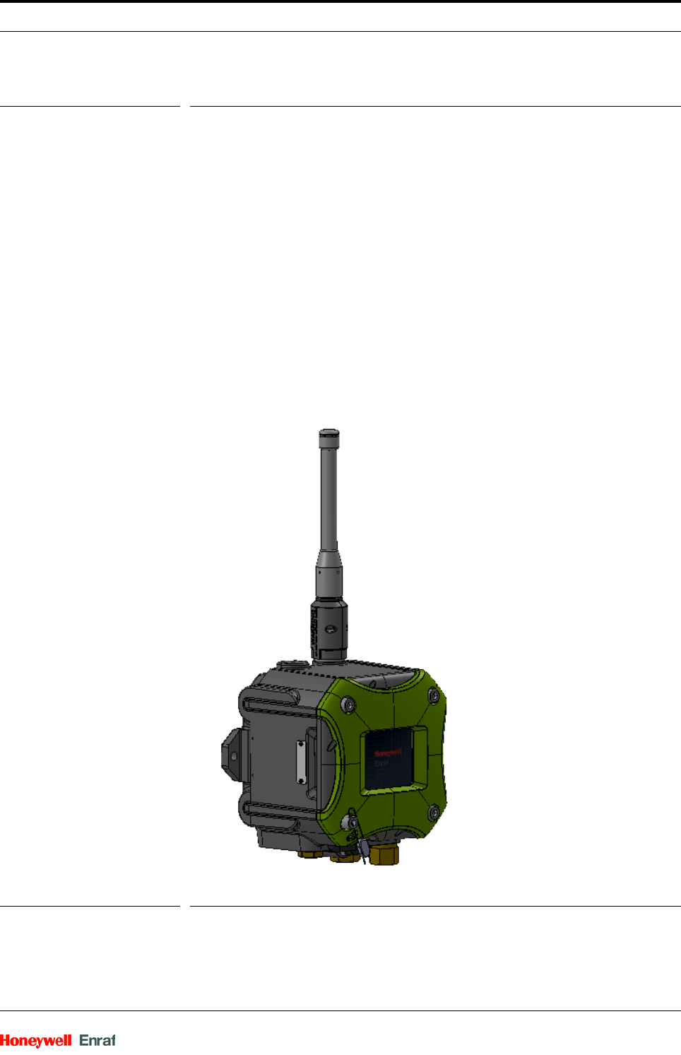
The Wireless Field Interface (WFI) adds a wireless capability to the
existing servo or the radar gauge by supporting the GPU protocol which
is compliant with the ISA100 standards. It consists of multiple electronic
boards, an antenna cable, and an antenna. The WFI communicates
with the servo or the radar gauge through the Honeywell Enraf field bus
Bi-Phase Mark, processes the data, and forwards the information
wirelessly to the Wireless Device Manager (WDM) which is compliant
with the ISA100 standards. The complete network including the WFI is
based on the ISA100 wireless field device network.
Also, there are different ways of communication which are as follows:
The protocol tunnel (Engauge and Entis)
Function blocks (Experion integration)
FIGURE 1-1 Wireless Field Interface (WFI)

General - Target Audience for this Manual
Wireless Field Interface Part No.: Rev01
1 - 2 Installation Manual
1.2 Target Audience for this Manual
This manual is intended for engineers and technicians, who are
assigned to install, commission, and service the WFI. Also, all
Honeywell Enraf customers who use wireless.
Safety - Safety Conventions
Part No.: Rev01 Wireless Field Interface
Installation Manual 2 - 1
CHAPTER 2 SAFETY
2.1 Safety Conventions
2.1.1 Warnings
The following warning mark is used within this document to urge
attention in order to prevent personal injuries or dangerous
situations, further described in this document.
2.1.2 Cautions
The following caution mark is used within this document to urge
attention in order to prevent damages to the equipment, further
described in this document.
Symbol Description Remark
General warning Will always be explained by text.
Symbol Description
General caution sign
Electrostatic Discharge (ESD) sensitive device
Safety - Safety Instructions for the WFI
Wireless Field Interface Part No.: Rev01
2 - 2 Installation Manual
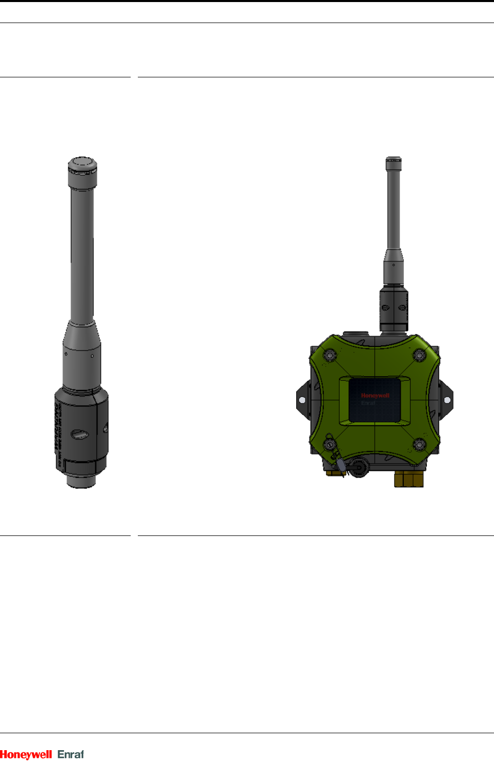
2.2 Safety Instructions for the WFI
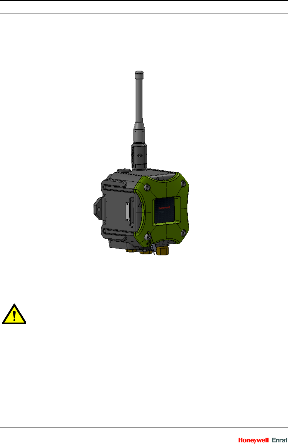
The WFI device is used for converting the wired communication of
various Honeywell Enraf equipment into a wireless transmission.
FIGURE 2-1 Wireless Field Interface (WFI)
2.2.1 General
WARNING! You must strictly follow the safety instructions
mentioned in this manual and the safety instructions
shipped with the WFI device for installation, commis-
sioning, operation, and maintenance, for the safe
operation of the WFI device.
Safety - Safety Instructions for the WFI
Part No.: Rev01 Wireless Field Interface
Installation Manual 2 - 3
The WFI may be located in explosion safety areas as follows:
2.2.1.1 EC declaration of conformity (for EU)
Refer to the EC declaration of conformity and the ATEX certificate(s),
shipped with the WFI device for EC declarations.
2.2.1.2 Control Drawings for FM and CSA
Refer to the control drawings shipped with the WFI for FM and CSA.
2.2.1.3 Users
The mechanical and electrical installation must be performed only by
trained people with the knowledge of the requirements for installation of
explosion proof equipment in hazardous areas.
The entire installation procedure for the WFI must be implemented in
accordance with national, local, and company regulations.
The entire electrical installation may be performed in accordance with
the national requirements for electrical equipment to be installed in
hazardous areas.
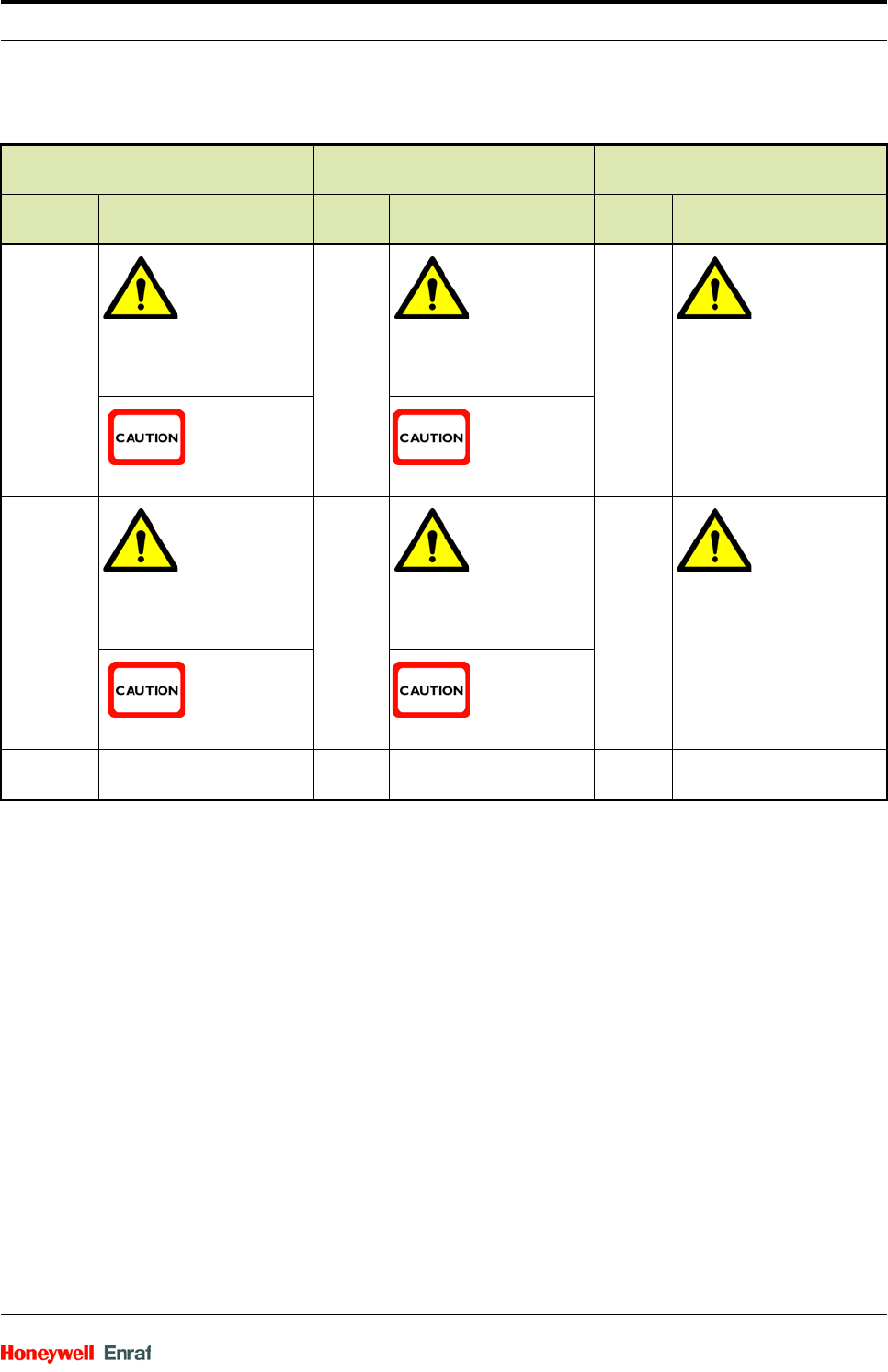
USA (FM) and Canada (CSA) Canada (CSA) Rest of the World
(ATEX / IECEx)
Safety
level Remarks Safety
level Remarks Safety
level Remarks
Class 1,
Division 1
WARNING!
Do NOT open
when an
explosive
atmosphere
may be
present.
Zone 1 WARNING!
Do NOT open
when an
explosive
atmosphere
may be
present.
Zone 1 WARNING!
Do NOT open
when an
explosive
atmosphere
may be
present.
CAUTION!
Seal conduit
within 18
inches.
CAUTION!
Seal conduit
within 18
inches.
Class 1,
Division 2
WARNING!
Do NOT open
when an
explosive
atmosphere
may be
present.
Zone 2 WARNING!
Do NOT open
when an
explosive
atmosphere
may be
present.
Zone 2 WARNING!
Do NOT open
when an
explosive
atmosphere
may be
present.
CAUTION!
Seal conduit
within 18
inches.
CAUTION!
Seal conduit
within 18
inches.
Safe Area - Safe
Zone
-Safe
Zone
-
Safety - Safety Instructions for the WFI
Wireless Field Interface Part No.: Rev01
2 - 4 Installation Manual
NOTE: See EN IEC 60079-14 document for more infor-
mation.
2.2.1.4 Additional information
For additional information about Honeywell Enraf solutions, see the
back cover of this manual to contact Honeywell Enraf or its
representative.
2.2.1.5 Environmental Conditions
The environmental conditions regarding the permissible operating
temperature for the WFI is -40 °C to +65 °C (-40 °F to +149 °F). The
relative humidity is RH 5 to 95%, non-condensing.
2.2.2 Personal Safety
WARNING! In hazardous areas, it is compulsory to use personal
protection and safety gear.
Safety can be achieved by using the following
equipment:
1. Safety helmet
2. Fire-resistive overall
3. Safety shoes
4. Safety glasses
5. Working gloves
6. LEL-meter
Pay attention to the kind of product involved. If there
is any danger to your health, wear a gas mask and
take all the necessary precautions.
WARNING! Take appropriate precautions when chemical or toxic
product vapors are present (compressed air,
chemical protection suit, detection equipment).
2.2.2.1 General
2.2.2.1.1 Repairs and Maintenance
WARNING! Any repairs or parts replacements must be
performed by the manufacturer or its appointed
repair agent.
2.2.2.1.2 Opening of the Device
WARNING! It is forbidden to open the WFI device within an
explosive hazardous environment in power, unless
otherwise stated on the safety label.
WARNING! Treat the flange surface of the cover and the housing
with care.
Keep the flange surface free of dirt.
The O-ring must be present and undamaged.

Safety - Safety Instructions for the WFI
Part No.: Rev01 Wireless Field Interface
Installation Manual 2 - 5
2.2.2.1.3 Tools
WARNING! Use non-sparking tools and explosion-proof testers.
Use suitable explosion-proof tools (for example,
testing devices).
2.2.2.1.4 Working Environment
WARNING! Avoid generation of static electricity. Make sure the
explosive gas mixtures are not available in the
working area.
2.2.2.1.5 Required Skills
WARNING! The technician must have technical skills to be able
to safely install the WFI device. The technician also
must be trained to work in accordance with the
national requirements for electrical equipment in
hazardous areas.
2.2.2.2 Commissioning
The commissioning of the device is conducted by qualified engineers
trained by Honeywell Enraf and with the knowledge of the (local and
national) requirements for electrical equipment in (potentially) explosive
atmospheres.
2.2.2.3 Maintenance and troubleshooting
If the WFI device does not function accurately, only a qualified service
engineer, trained by Honeywell Enraf and with the knowledge of safety
regulations for working in (potentially) explosive atmospheres are
allowed to repair the WFI device.
2.2.2.4 Grounding
Make sure the housing of the device is properly connected to ground
reference. See FIGURE 3-5.
Make sure the electrical resistance of the ground connections is below
the maximum prescribed by local requirements.
2.2.3 Electrical
2.2.3.1 Safety Standards
The entire electrical installation must be in accordance with the Inter-
national Standard EN IEC 60079-14 for electrical equipment in
hazardous areas.
The stopping plugs, cable glands, and reducers must be installed in
accordance with the appropriate IP requirements.
Use the bolts that are property class A2-70 or better captured types
and are not user replaceable. Contact Honeywell Enraf if you need to
replace the bolts.
Use suitable flameproof (Ex d) compound cable glands or conduit
seals.

Safety - Safety Instructions for the WFI
Wireless Field Interface Part No.: Rev01
2 - 6 Installation Manual
Improper installation of cable glands, threaded adaptors, stopping
plugs, and their interface invalidates the Ex approval of the WFI
device.
Accurate dimensions of the flameproof joints must be used. Contact
Honeywell Enraf for information regarding the dimensions of the
flameproof joints.
2.2.3.2 Accordance to Regulations
2.2.3.3 Explosion Safety
2.2.3.4 Compliance to FCC
This device complies with Part 15 of the FCC Rules. The WFI device
does not cause any harmful interference and accepts any interference
received.
2.2.3.5 Low-Voltage Directive
The device is suitable for 2006/95/EC.
The applicable standard value is IEC 61010-1 (3rd Edition).
2.2.3.6 Reference of Applicable Standards
Approval Certificate no. Type of protection identification
ATEX Approval pending II 2 G
Ex d [ia] IIB T6 Gb
Ta = -40 °C ... +65 °C
(-40 °F ... +149 °F)
IECEx Approval pending Zone 1
FM Approval pending Class I, Division 1 group C, D T6
CSA Approval pending
Class I, Division 1 group C, D T6
Zone 1 Ex d [ia] IIB T6
Standard Description
ATEX 95 Applicable for manufacturers of equipment used in places
where explosion danger may exist.
IECEx The IECEx System is an International Conformity System
where a Mark of Conformity is granted by approved IECEx
certifiers (ExCBs) located in IECEx participating countries for
equipment that is covered by an IECEx Certificate of Confor-
mity and hence has been tested and manufactured under
systems that are under ongoing surveillance by ExCBs.
FM Factory Mutual Approvals Division
The Factory Mutual Approvals Division determines the safety
and reliability of equipment, materials, or services utilized in
hazardous locations in the United States and elsewhere.
CSA Canadian Standards Association
The standards generated by CSA are the cornerstone for
determining a product's eligibility for certification in
hazardous locations in Canada.
Safety - Safety Instructions for the WFI
Part No.: Rev01 Wireless Field Interface
Installation Manual 2 - 7
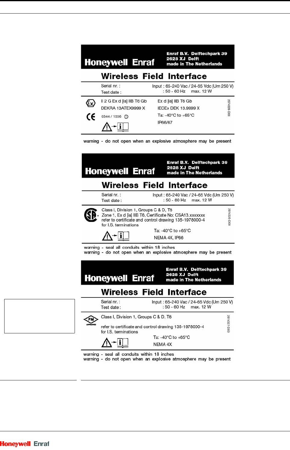
2.2.3.7 WFI Labels
FIGURE 2-2 Identification labels with Safety note on the WFI
NOTE to FM label:
Ta = -40 °F to +149 ºF
Safety - Liability
Wireless Field Interface Part No.: Rev01
2 - 8 Installation Manual
2.3 Liability
The information in this installation guide is the copyright property of
Honeywell International Inc. Honeywell International Inc. disclaims any
responsibility for personal injury or damage to equipment caused by:
Deviation from any of the prescribed procedures.
Execution of activities that are not prescribed.
Neglect of the safety regulations for handling tools and use of elec-
tricity.
The contents, descriptions, and specifications in this manual are subject
to change without notice. Honeywell International Inc. accepts no
responsibility for any errors that may appear in this manual.
WARNING! Only certified technicians are authorized to make
changes to the WFI configuration. All modifications
must be in accordance with the guidelines as set
forth by Honeywell International Inc. Modifications
not authorized by Honeywell International Inc. inval-
idates the approval certificates.
System Description - Introduction
Part No.: Rev01 Wireless Field Interface
Installation Manual 3 - 1
CHAPTER 3 SYSTEM DESCRIPTION
3.1 Introduction
3.2 System Architecture
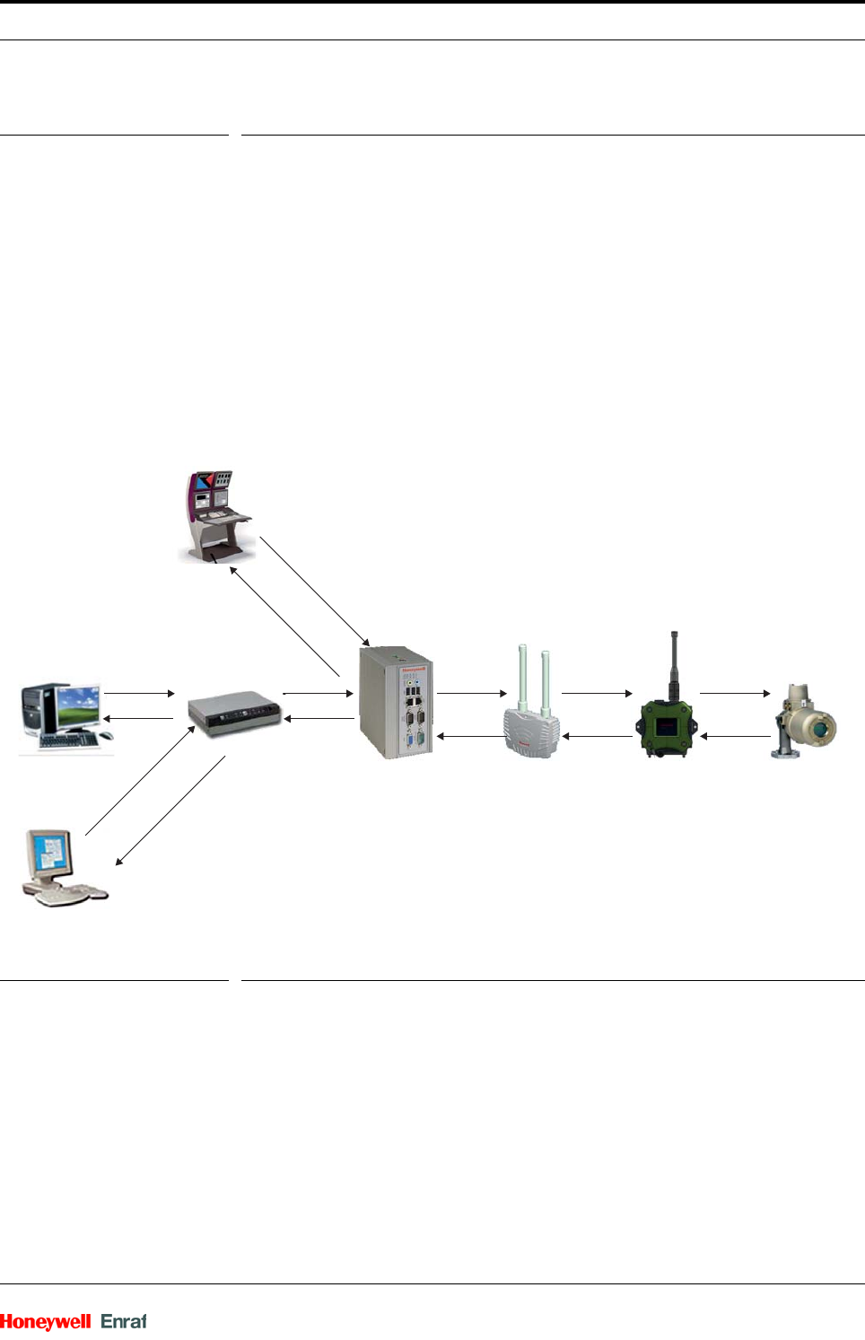
The WFI is a box that can be installed next to an installed Servo/Radar
gauge. The WFI retrieves the information from this gauge and sends the
information wirelessly to the supervisory level.
This is an ISA100 compliant solution that supports transducer blocks for
transferring basic process values to the supervisory level and supports
the GPU tunnel to connect to the Engauge (maintenance) and Entis
(inventory management package) systems. See FIGURE 3-1.
FIGURE 3-1 WFI architecture overview
3.3 FlexConn Modules
3.3.1 General
One of the main characteristics of the FlexConn architecture is the
placement flexibility of the FlexConn modules. The backbone of this
Entis CIU
WDM
Engauge service tool
FDAP
WFI
Servo Gauge
BPM Interface
ISA100 Wireless
Interface
Experion
System Description - FlexConn Modules
Wireless Field Interface Part No.: Rev01
3 - 2 Installation Manual
concept is the serial CAN1 bus to which each FlexConn module
connects.
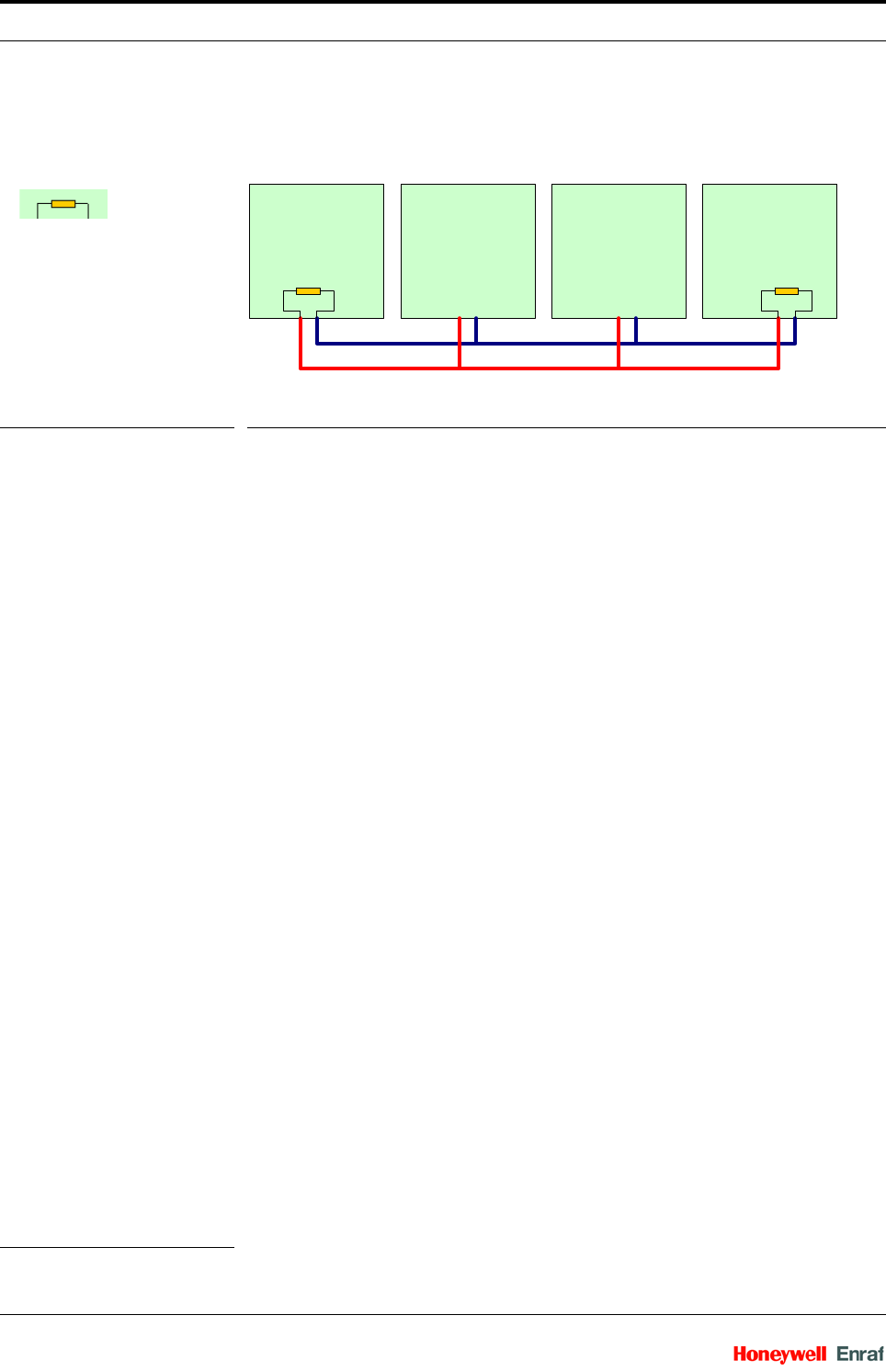
FIGURE 3-2 FlexConn CAN bus concept
Inside the enclosure, the following modules are available.
FII-SMV or Spare Module
HCW-1WL
FCW-BPM
The stack of modules are mounted on the DIN Rail and placed vertically
inside the enclosure as illustrated in FIGURE 3-3.
1. Controller Area Network.
FII-SMV/SPARE HCW-1WL FCW-BPM CAN-PSX
CAN-L
CAN-H
= terminating resistor
System Description - FlexConn Modules
Part No.: Rev01 Wireless Field Interface
Installation Manual 3 - 3
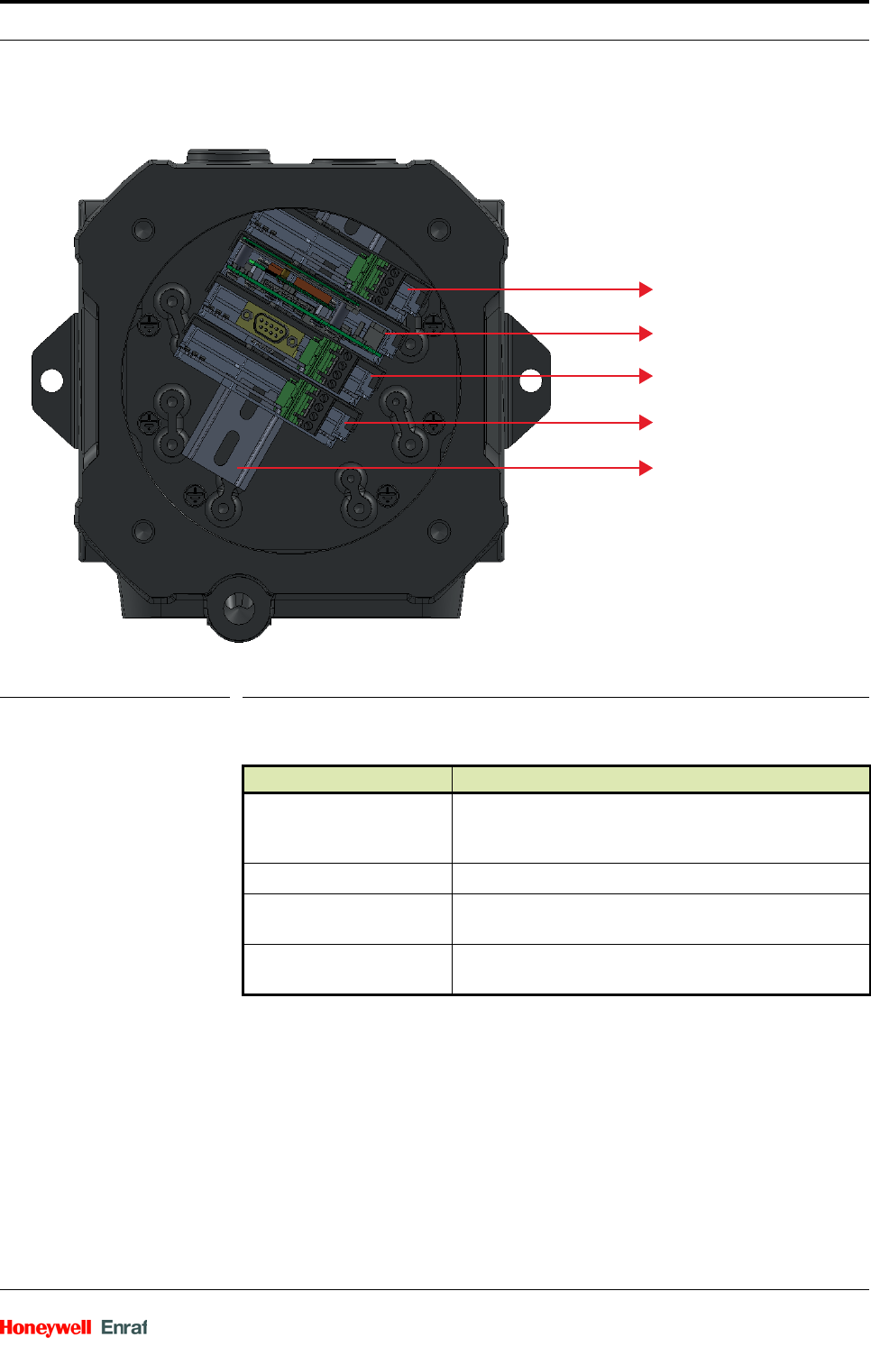
FIGURE 3-3 FlexConn board sequencing
3.3.2 Grounding Concept
Each printed circuit board has 2 grounding points. These grounding
points are used to electrically connect every board with the metal
housing. This is performed by means of metal spacers, which are
pressed into the boards. See FIGURE 3-4.
Module Description
Radio Board Includes the circuit of 1WL Main Board and Carrier
Boards. It is assembled with DFSS Radio or LCRB and
Barrier Boards.
CAN-PSX Generates the power of 15 V DC with auxiliary supply.
CAN-BPM Provides an interface to a BPM based Enraf field bus to
communicate with Servo/Radar Gauge.
FII-SMV Connects the display type SmartView with a standard
CAN bus.
FII-SMV/SPARE
Radio Board
FCW-BPM
CAN-PSX
DIN rail
System Description - FlexConn Modules
Wireless Field Interface Part No.: Rev01
3 - 4 Installation Manual
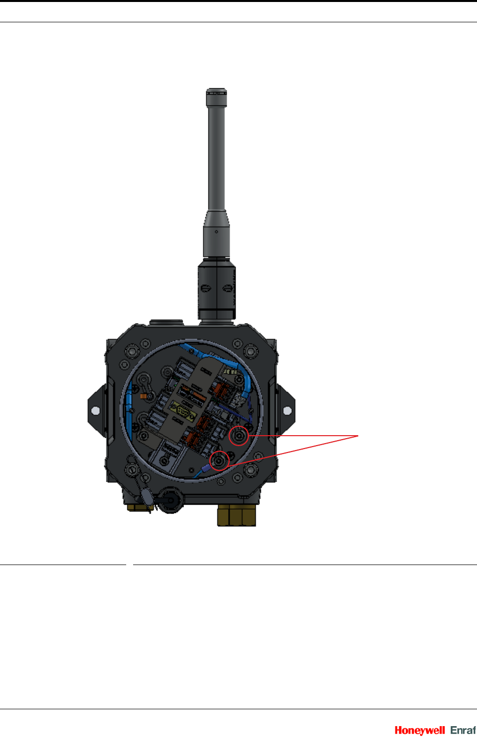
FIGURE 3-4 Grounding concept
3.3.3 Enclosure Earth Details
Inside the enclosure, 2 Protected Earthing (PE) or Mains input earth
points and 1 external point is available to connect to the field earth
point. See FIGURE 3-5.
Grounding points
System Description - FlexConn Modules
Part No.: Rev01 Wireless Field Interface
Installation Manual 3 - 5
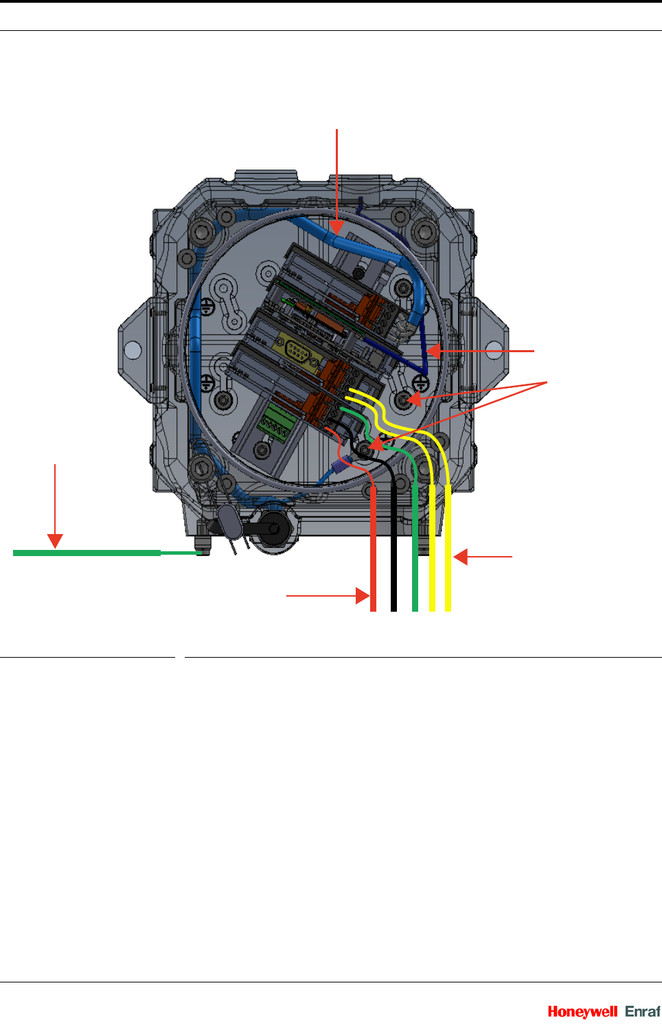
FIGURE 3-5 The grounding connections for the WFI
3.3.4 Field Wiring
The mains input and the CAN-BPM signal lines enter the enclosure
through different glands from one side of the enclosure.
The mains input (Line and Neutral) cable wires terminate on the PSX
module connector. The mains input earth wire terminates on one of the
PE points provided inside the enclosure. From the PE point inside the
enclosure, the PSX gets the PE connection through the wire terminated
on the PSX connector.
The CAN-BPM signals cable from the servo gauge enters the enclosure
with the gland and terminates on the CAN-BPM module connector. The
CAN-BPM module then gets the earth wire from the PE point inside the
enclosure. See FIGURE 3-6.
System Description - FlexConn Modules
Wireless Field Interface Part No.: Rev01
3 - 6 Installation Manual
FIGURE 3-6 Field wiring
FII-SMV cable
Field Earth
(External)
Mains Input
BPM Interface cable
Ground Points
Antenna Coaxial Cable
System Description - FlexConn Modules
Part No.: Rev01 Wireless Field Interface
Installation Manual 3 - 7
3.3.5 PCB Details
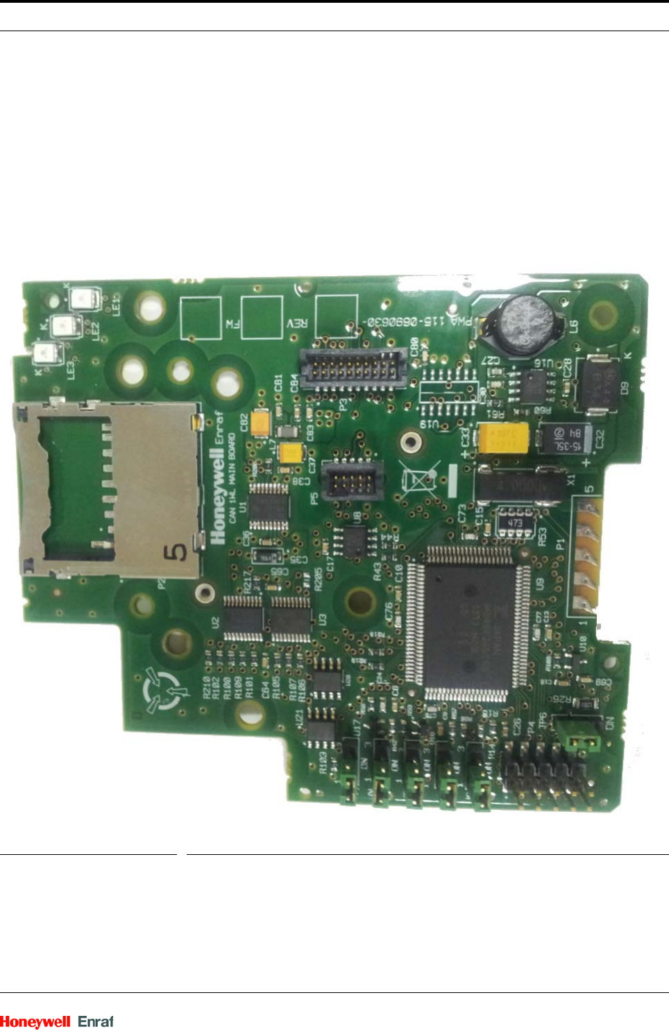
3.3.5.1 CAN-1WL Board
The CAN-1WL board is used to interface data between a FlexConn
system and the OneWireless network (including the antenna).
The 1WL main board occupies a single slot in the FlexConn rail and the
other three boards (1WL carrier board, 1WL radio board, and 1WL
barrier board) are mounted together to form the second FlexConn
board. See FIGURE 3-7.
FIGURE 3-7 CAN-1WL board layout
The functions of the CAN-1WL board are as follows:
1WL main board
• FlexConn electronics
System Description - FlexConn Modules
Wireless Field Interface Part No.: Rev01
3 - 8 Installation Manual
• 3V3 power supply
• SD card interface
• 5V / 3V3 level converter
1WL carrier board
• Filter the 3V3 power supply
1WL radio board
• OneWireless radio board
1WL barrier board
• Barrier board
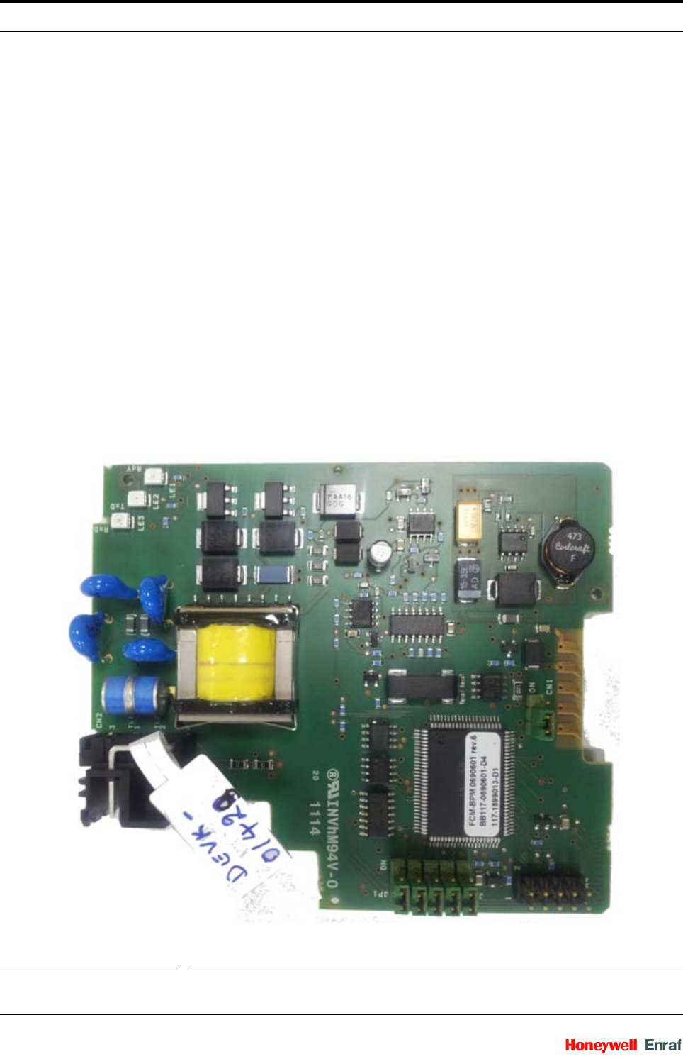
3.3.5.2 CAN-BPM module
3.3.5.2.1 Functions
The CAN-BPM module provides an interface to a BPM based Enraf field
bus. It is a communication print that is based on Flexconn and can be
installed in a SmartLink (new CIU) or in a new instrument such as a
Flexconn based radar or servo gauge. The CAN-BPM print in a
SmartLink is called FCM-BPM module. See FIGURE 3-8.
FIGURE 3-8 CAN-BPM board layout

System Description - FlexConn Modules
Part No.: Rev01 Wireless Field Interface
Installation Manual 3 - 9
3.3.5.2.2 Terminal Descriptions
CN2 - BPM
LEDs
3.3.5.3 FII-SMV (HMI-TSI)
3.3.5.3.1 Functions
The FII-SMV (HMI-TSI) module is intended to connect the display type
SmartView with a standard CAN bus. The display is an intrinsic safe
device. The interface module is located within an Ex d enclosure or in a
safe area and provides intrinsic safe circuits for the supply and
communication to the display module. See FIGURE 3-9.
The module implements the following functions.
Pin no. Name/Signal
1TL1
2TL2
3n.c/spare
4 PE (optional)
Items Description
LE1 Error indication
LE2 Follows TxD on BPM line (TXEFB1)
LE3 Follows RxD on BPM line (RXEFB)
Function Description
Supply 10 V Safe_+ = 10V for the SmartView display module, isolated (Ex certified)
RS485 RS485 for the SmartView display module, isolated (Ex certified)
Local service Software, processing messages from/to the SmartView display unit and
CAN-BUS
Display interface Software, processing messages from/to the SmartView display unit and
CAN-BUS
System Description - FlexConn Modules
Wireless Field Interface Part No.: Rev01
3 - 10 Installation Manual
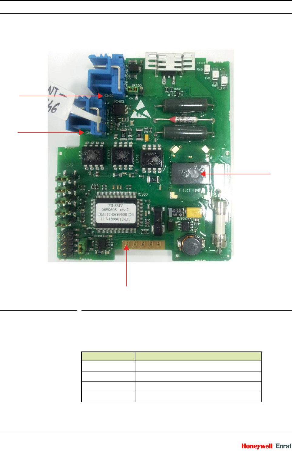
FIGURE 3-9 FII-SMV board layout
3.3.5.3.2 Terminal Descriptions
LE1 is connected to the Vdc output signal.
Connectors
Connectors Description
CN1 CAN-BUS
CN2 Display output
CN3 Display output
CN4 Program Header
CN2
CN3
CN1
TR1

System Description - FlexConn Modules
Part No.: Rev01 Wireless Field Interface
Installation Manual 3 - 11
CN1
CN2
CN4
LEDs
Jumpers
Pin no. Name/Signal
1W&M
2CAN_H
3CAN_L
4V
dc = + 15 V
5GND
Pin no. Name/Signal Description
1 SGND Isolated secondary ground
2 Vsafe_+ Isolated DC supply output
3 Safe_A Isolated RS485 A input/output
4 Safe_B Isolated RS485 B input/output
Pin no. Name/Signal
1P00
2P01
3MD0
4MD2
5RST
6SIN0
7SOT0
8SCK0
9V
cc
10 GND
Items Description
LE1 Error indication
LE2 Application specific
LE3 Application specific
Items Description
JP1 W&M entities protection
JP2 Password read protection
JP3 Write protection all entities

System Description - FlexConn Modules
Wireless Field Interface Part No.: Rev01
3 - 12 Installation Manual
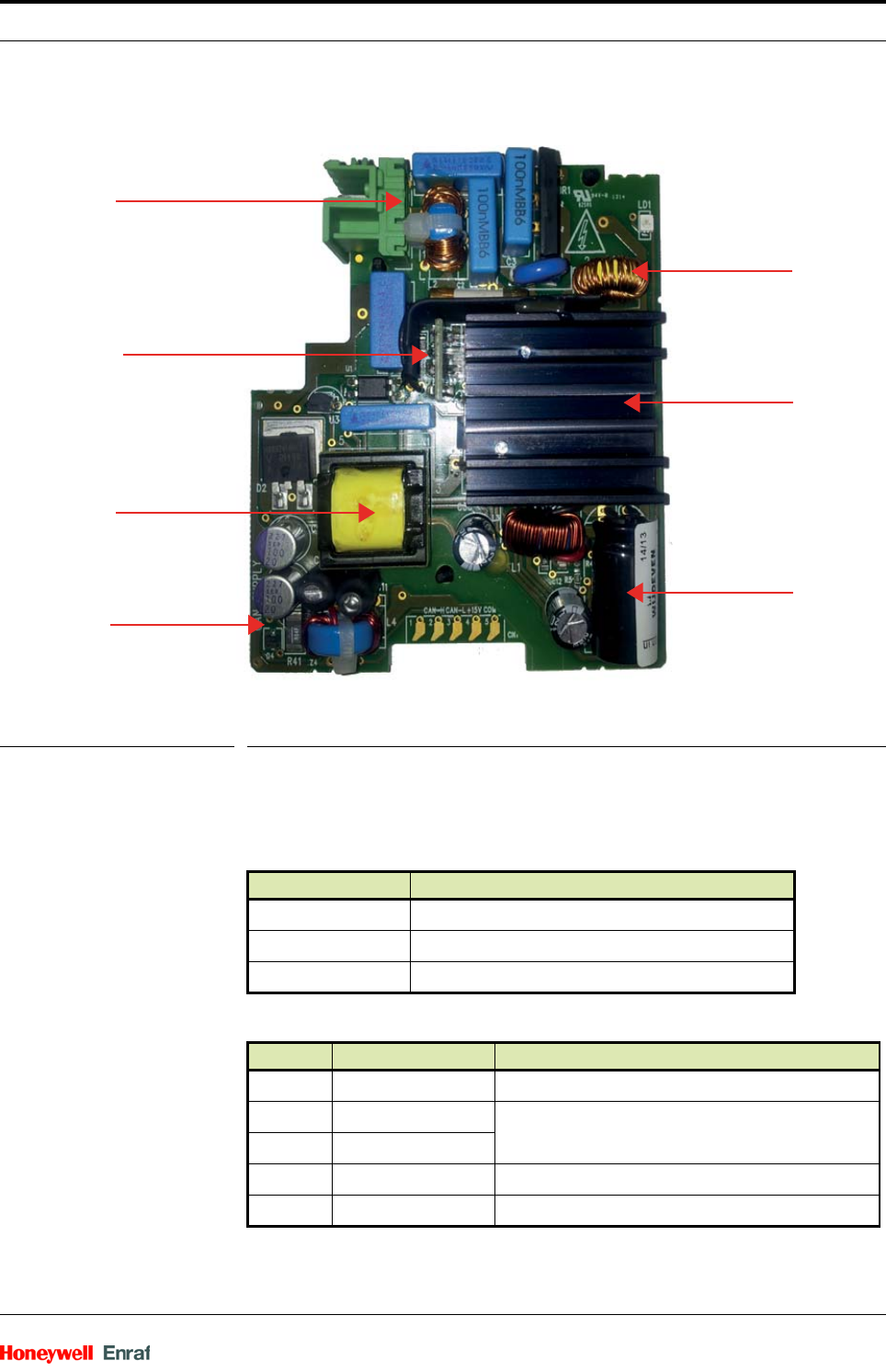
3.3.6 CAN-PSX module - Power Supply
3.3.6.1 Functions
The CAN Power supply (+15V DC) is intended to power up the
FlexConn modules. It can be used within the application and also within
an Ex-d enclosure. See FIGURE 3-10.
The module implements the following specifications.
JP4 Spare
JP5 Spare
JP6 Termination of CAN-bus
Item Specification
AC Input Voltage Range 65 V - 240 V AC (+10% to -15%)
Input Frequency 50 Hz to 60 Hz ±10%
Input Fuse Value 1.25 A
Isolation Voltage 4.3 KV
DC Input Voltage Range 24 V - 65 V DC (+10% to -15%)
Output Voltage 15 V DC ± 4%
Continuous current 1 A
Items Description
System Description - FlexConn Modules
Part No.: Rev01 Wireless Field Interface
Installation Manual 3 - 13
FIGURE 3-10 CAN-PSX board layout
3.3.6.1.1 Terminal Descriptions
LE1 is connected to the Vdc output signal.
Connectors
CN1
Connectors Description
CN1 CAN-BUS
CN2 Mains/DC input
CN3 Not placed
Pin no. Name/Signal Description
1n.c.
2 CAN_H Interconnected by 120Ω 1206
3CAN_L
4V
dc = + 15 V
5GND
aInternally connected to CN2, earth PE
CN2
Switch board
Main board
Storage
Heatsink
Boost coil
TX1

System Description - FlexConn Modules
Wireless Field Interface Part No.: Rev01
3 - 14 Installation Manual
CN2 (AC/DC input)
a. CN1 pin 5 may not be used as an
extension on the protective earth.
However, it may be used as a functional
earth pin.
Pin no. Name / signal Description
1V
in_a Mains or DC + / - input
2V
in_b Mains or DC + / - input
3 PE Earth = PE = GND
4n.c
Installation - Mounting the Antenna
Part No.: Rev01 Wireless Field Interface
Installation Manual 4 - 1
CHAPTER 4 INSTALLATION
4.1 Mounting the Antenna
The antenna is placed on top of the WFI enclosure as shown in the
following figure.
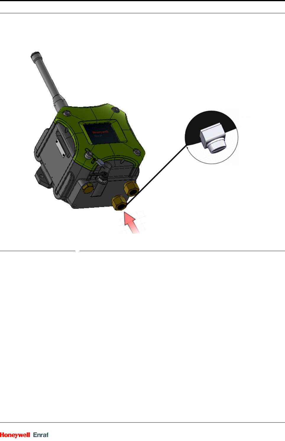
FIGURE 4-1 WFI antenna
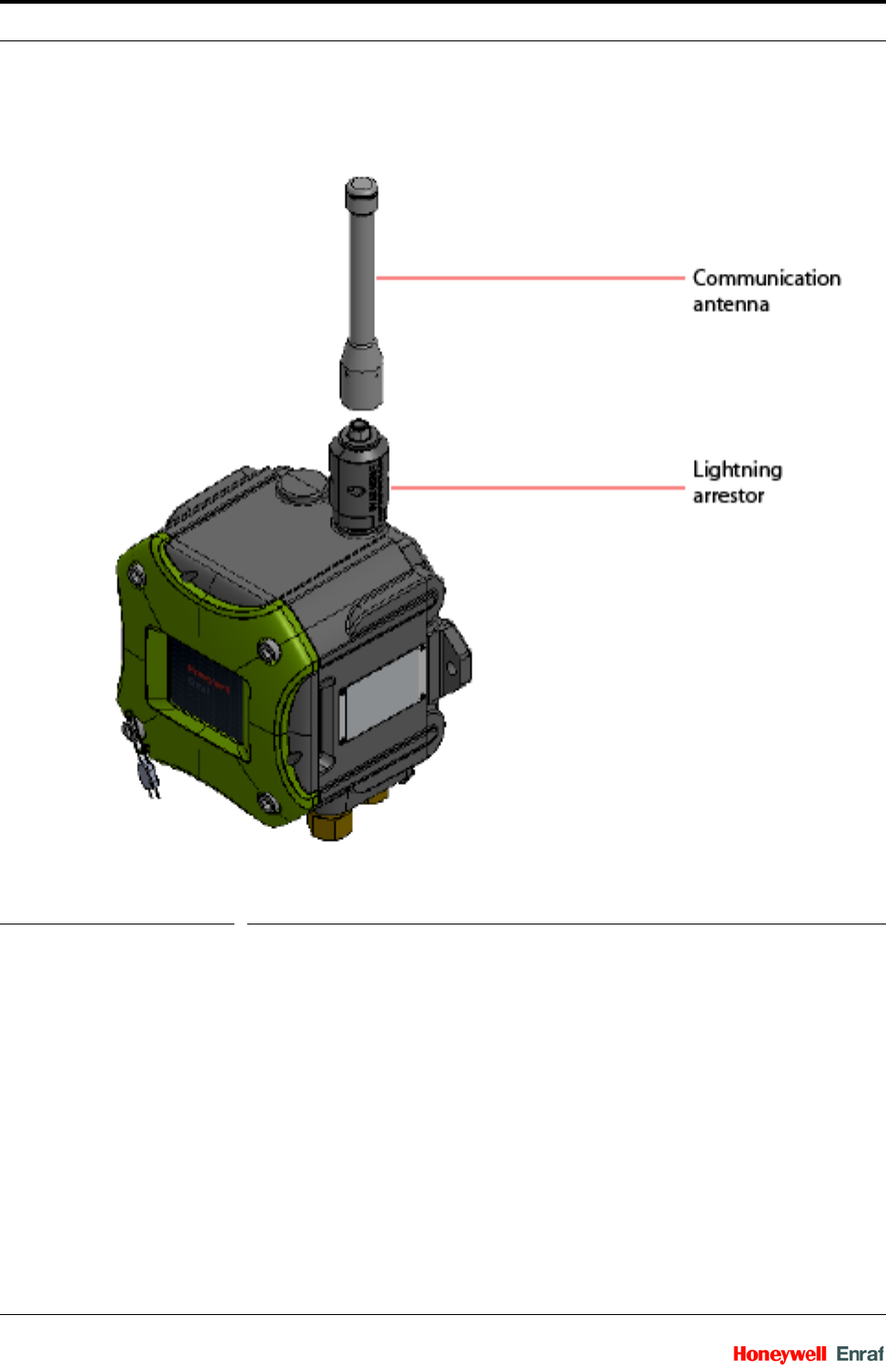
To mount the communication antenna on the WFI device, screw the
communication antenna clockwise on the lightning arrestor. See
FIGURE 4-2.
Installation - Mounting the Antenna
Wireless Field Interface Part No.: Rev01
4 - 2 Installation Manual
FIGURE 4-2 Mounting the communication antenna
NOTE: The lightning arrestor protects the inside electronics
from the lightning damage. Although it protects
against multiple discharges, it can be replaced as a
preventive maintenance action. Preventive main-
tenance interval depends on the location, position of
the equipment, grounding, and other protection
measures installed.
4 dBi and 8 dBi integral antenna’s are supported in WFI.
For more information about the antenna types supported, refer to the
SmartRadar FlexLine Service Manual.

Installation - Mounting Dimensions
Part No.: Rev01 Wireless Field Interface
Installation Manual 4 - 3
4.2 Mounting Dimensions
NOTE: This section will be updated when the mounting
dimensions for the WFI is finalized.

Installation - Mounting Dimensions
Wireless Field Interface Part No.: Rev01
4 - 4 Installation Manual