Honeywell 51306799 SmartRadar Flexline User Manual Manual
Honeywell International Inc. SmartRadar Flexline Manual
Contents
Manual
___________________________________________________________________________
__________________________________________________________________________________________
LCRMUserManualPage1of11RevisionNo3.0April28,2013
LowcostRFModule(LCRM)‐UserManual
ProductManual
ForRFModulepartnumbers,
RadioAssembly:51306799
Printedwiringboardno:51306798
2.4GHz,802.15.4Module
Copyright2013byHoneywellInternationalInc.
Revision3,April28,2013

___________________________________________________________________________
__________________________________________________________________________________________
LCRMUserManualPage2of11RevisionNo3.0April28,2013
DocumentRevisionHistory
DateAuthorDescription/ChangesRevision
Feb22,2011AbhijitInitial1.0
May30,2011BiswasModifiedafterReviewwithTUV2.0
April28,2013AntonyRe‐ReleasedforC2PC3.0
___________________________________________________________________________
__________________________________________________________________________________________
LCRMUserManualPage3of11RevisionNo3.0April28,2013
Contents
1.COMPLIANCESTATEMENTS:................................................................................................................4
1.1FCCCOMPLIANCESTATEMENTS.......................................................................................................................4
1.2ICCOMPLIANCESTATEMENTS..........................................................................................................................5
2.DESCRIPTION:.....................................................................................................................................6
3.FEATURES:..........................................................................................................................................6
4.ELECTRICALCHARACTERISTICS............................................................................................................6
5.PINOUTDETAILS.................................................................................................................................6
6.MECHANICALSPECIFICATION..............................................................................................................7
7.CONFIGURATIONSOFTWARE..............................................................................................................8
8.APPROVEDANTENNATYPES/GAINS...................................................................................................8
9.SETTINGTXPOWER.............................................................................................................................9
10.INSTRUCTIONTOOEMINSTALLER.....................................................................................................10
11.LIMITEDMODULARAPPROVAL.........................................................................................................11
12.AGENCYLABELINFORMATION..........................................................................................................11

___________________________________________________________________________
__________________________________________________________________________________________
LCRMUserManualPage4of11RevisionNo3.0April28,2013
1. Compliance Statements:
1.1 FCC Compliance Statements
This device complies with Part 15 of the FCC rules. Operation is subject to following
two conditions:
1. This device may not cause harmful interference and
2. This device must accept any interference received including interference that may cause
undesired operation of this device.
The changes or modifications not expressly approved by the party responsible for
compliance could void the user’s authority to operate the equipment.
To comply with the FCC RF exposure compliance requirements, this device and its antenna
must not be co-located or operating to conjunction with any other antenna or transmitter,
except if installed in compliance with FCC Multi Transmitter procedures.
To inherit the modular approval, the antennas for this transmitter must be installed to provide
a separation distance of 20cm from all persons and must not be co-located or operating in
conjunction with any other antenna or transmitter
To OEM Installer:
1. FCC ID on the final system must be labeled with “Contains FCC ID: S5751306799” Or
“Contains transmitter module FCC ID: S5751306799”.
2. In the user manual, final system integrator must ensure that there is no instruction
provided in the user manual to install or remove the transmitter module.
3. Transmitter module must be installed used in strict accordance with the manufacturer’s
instructions as described in the user documentation that comes with the product.
The user manual of the final host system must contain the following statements:
This device complies with Part 15 of the FCC rules. Operation is subject to following
two conditions: 1. This device may not cause harmful interference and 2. This device
must accept any interference received including interference that may cause undesired
operation of this device.
The changes or modifications not expressly approved by the party responsible for
compliance could void the user’s authority to operate the equipment.
To comply with the FCC RF exposure compliance requirements, this device and its antenna
must not be co-located or operating to conjunction with any other antenna or transmitter,
except if installed in compliance with FCC Multi Transmitter procedures.
To inherit the modular approval, the antennas for this transmitter must be installed to provide
a separation distance of at least 20cm from all persons and must not be co-located or
operating in conjunction with any other antenna or transmitter
Note:
The buyer of the module who will incorporate this module into his host must submit the final
product to the manufacturer of the module and the MANUFACTURER OF THE MODULE
WILL VERIFY that the product is incorporated in host equipment in a way that is represented
by the testing as shown in the test report.

___________________________________________________________________________
__________________________________________________________________________________________
LCRMUserManualPage5of11RevisionNo3.0April28,2013
1.2 IC Compliance Statements
Operation is subject to the following two conditions:
1. This device may not cause interference, and
2. This device must accept any interference, including interference that may cause undesired
operation of the device.
Under Industry Canada regulations, this radio transmitter may only operate using an antenna
of a type and maximum (or lesser) gain approved for the transmitter by Industry Canada.
To reduce potential radio interference to other users, the antenna type and its gain should be
so chosen that the equivalent isotropically radiated power (e.i.r.p.) is not more than that
necessary for successful communication.
Conformément à la réglementation d'Industrie Canada, le présent émetteur radio peut
fonctionner avec une antenne d'un type et d'un gain maximal (ou inférieur) approuvé pour
l'émetteur par Industrie Canada.
Dans le but de réduire les risques de brouillage radioélectrique à l'intention des autres
utilisateurs, il faut choisir le type d'antenne et son gain de sorte que la puissance isotrope
rayonnée équivalente (p.i.r.e.) ne dépasse pas l'intensité nécessaire à l'établissement d'une
communication satisfaisante.
This radio transmitter has been approved by Industry Canada to operate with the antenna
types listed below with the maximum permissible gain and required antenna impedance for
each antenna type indicated. Antenna types not included in this list, having a gain greater
than the maximum gain indicated for that type, are strictly prohibited for use with this device.
Le présent émetteur radio a été approuvé par Industrie Canada pour fonctionner avec les
types d'antenne énumérés ci-dessous et ayant un gain admissible maximal et l'impédance
requise pour chaque type d'antenne. Les types d'antenne non inclus dans cette liste, ou dont
le gain est supérieur au gain maximal indiqué, sont strictement interdits pour l'exploitation de
l'émetteur.
To inherit the modular approval, the antennas for this transmitter must be installed to provide
a separation distance of at least 20cm from all persons and must not be co-located or
operating in conjunction with any other antenna or transmitter
Note:
The buyer of the module who will incorporate this module into his host must submit the final
product to the manufacturer of the module and the MANUFACTURER OF THE MODULE
WILL VERIFY that the product is incorporated in host equipment in a way that is represented
by the testing as shown in the test report.

___________________________________________________________________________
__________________________________________________________________________________________
LCRMUserManualPage6of11RevisionNo3.0April28,2013
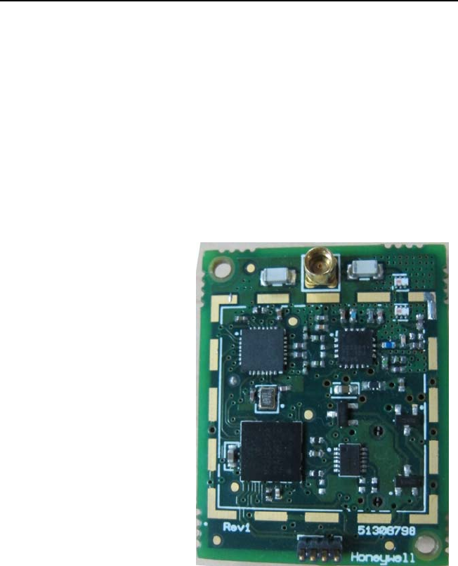
2. Description:
Low Cost ISA100 Radio Module is 2.4GHz band 802.15.4 Radio. This module includes 16 Bit
Microcontroller which is interfaced to a 802.15.4 compliant Radio Transceiver to provide
Wireless communication over 15Channels of 2.4GHz band. The module also includes RF
Power Amplifier and RF Low Noise Amplifier to enhance the range of Wireless
communications. The Module can communicate with the target boards through its connector
over SPI. It can send out or receive, data - sent by or sent to, the target board through this
SPI connection. Protocol specific Modulation/De-Modulation is done in radio transceiver and
the 802.15.4 packet is taken care by Radio Transceiver on the Module.
3. Features:
Operating frequency : 2.4 to 2.483GHz
No. of channel : 15
Channel spacing : 5MHz (2405,2410,…..2475)
Transmitted power : -7 to +20dBm (adjusted as per antenna)
Modulation : DSSS
Data rate : 250kbps
4. Electrical Characteristics
Operating Voltage : 2.7V to 3.6V
Operating Temperature : -40 deg C to +85 deg C.
Current Consumption:
Receive Mode (Rx) : 33mA
Transmit Mode(Tx) : 220mA
Sleep Mode : 13uA
Absolute Maximum Ratings
Volta
g
e Applied 3.6
Storage Temperature -50°C to +105°C
Operating Temperature -40°C to +85°C
5. Pin out Details
1 GND 2 GND
3 I/O 4 I/O
5 SPI_CLK 6 SPI_MISO
7 SPI_MOSI 8 SPI_CS
9 VCC 10 VCC
Table 1 Pin Out
___________________________________________________________________________
__________________________________________________________________________________________
LCRMUserManualPage7of11RevisionNo3.0April28,2013
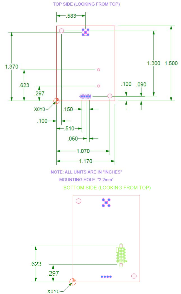
6. Mechanical Specification

___________________________________________________________________________
__________________________________________________________________________________________
LCRMUserManualPage8of11RevisionNo3.0April28,2013
7. Configuration Software
The radio platform can host multiple standard protocol stacks like ISA100, zigbee, 802.15.4 pt
to pt and any proprietary protocol stack which could use the same hardware platform running
on 802.15.4 physical layer. The configuration parameters for power level, frequencies are
adjusted as per the antenna table used during compliance tests. For compliance tests, test
software running hyper terminal is used to configure the power levels for the different antenna
as per the Table 2. The commands shall be available through host application to
communicate to the radio module for configuration of Tx power levels.
The power levels are configured in the registers of radio transceiver used on the module and
adjusted as per Table 2. The frequencies i.e 15 channels are pre-defined as per 802.15.4
arrangement in 2.4GHz band excluding the last channel i.e 16th channel, 2480MHz.
8. Approved Antenna Types/ Gains
Antenna
NumberMakeModelAntennaGain
(dBi)
PowerLevel
Setting(dBm)
Antenna1HyperlinkWHON511‐0001415
Antenna2AntennaFactorANT2.4OEMHSC002V12.215
Antenna3AntennaFactorANT2.4OEMHSC001V12.215
Antenna4AntennaFactorANT‐DB1‐VDP‐RPS3.015
Antenna5L‐COM/HyperlinkHG2405RD‐RSP5.511
Antenna6CenturionMAF94152‐2.020
Antenna7L‐COM/HyperlinkHG2409RD‐RSP9.011
Antenna8HyperlinkHGV‐2409U8.015
Antenna9L‐COM/HyperlinkHG2475U‐RNJ8.015
Antenna10HyperlinkHG2414P‐12014.011
Antenna11L‐ComHG2402RDR‐RSP2.215
Antenna12LairdTechRD2458‐5‐OTDR‐NM3.015
Antenna13LairdTechOD24M‐55.015
Table 2 Antenna Vs Transmit Power List
Antenna2,3,4,5,7&11arewithReverseSMAconnector.
Antenna1,8,9,10,12&13arewithNtypeconnector.
Antenna6iswithMMCXtypeconnector.
___________________________________________________________________________
__________________________________________________________________________________________
LCRMUserManualPage9of11RevisionNo3.0April28,2013
9. Setting Tx Power
Warning!The Low Cost ISA100 Radio Module must be Professionally Installed in
accordance with the requirements specified in this document. Only the specified power
Settings, antenna types and gains as outlined in this document are valid for Low Cost ISA100
Radio Module installation.
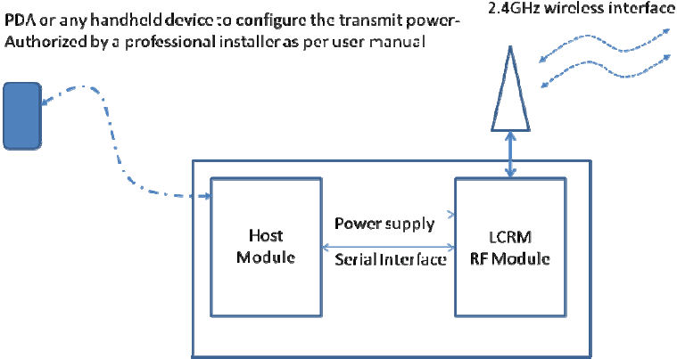
The Tx power settings for the radio module are to be configured using a host interface with
the module. The module has an SPI communication interface which can communicate to any
host carrier. The power settings are provided as configurable parameter through host
interface. The configurable parameter will be in terms of RF output power in dBm available at
the connector output of the radio board as given in the figures below,
Alternatively power levels can be preconfigured in LCRM RF module in factory as per the
antenna combination being shipped out with the product.
LCRM module can host different types of communication stack software like ISA100, Zigbee,
15.4 pt to pt etc..which can typically use 15.4 physical layer for the wireless communication.
Irrespective of the communication stack being ported on the LCRM module, the basic
configurations of channels and power levels as per the antenna shall remain same as given in
the user manual. As explained above, this can be either done through a professional
installation at the field or through a preconfigured power level with a particular antenna
combination shipped out from factory.
Professional installation has to be done by a person who has sufficient knowledge about
settings of radio parameters of the module. It will void OEM installers authority to operate and
sell the equipment if this is done incorrectly.

___________________________________________________________________________
__________________________________________________________________________________________
LCRMUserManualPage10of11RevisionNo3.0April28,2013
The power level configurable are given in Table 3
S.NoPowerlevel
120dBm
219dBm
318dBm
417dBm
515dBm
614dBm
712dBm
811dBm
910dBm
106dBm
114dBm
123dBm
131dBm
140dBm
15‐1dBm
16‐5dBm
Table 3 Power Level Supported by LCRM
10. Instruction to OEM installer
OEM installer shall refer user manual for configuration of transmit power for type of antenna
as given in Table 2.
The antennas listed in Table 2 includes N type connector, Reverse SMA connector and
MMCX connector. Installer shall use only the antennas which are listed in the table to comply
with FCC regulations.
Integrators of this module in their end product are instructed to glue the N type antenna
connector to the socket of the final product.
For the final product OEM installer must ensure that the power settings of the module are not
end user accessible.
When integrated into OEM products, fixed antennas require installation preventing end-users
from replacing them with non-approved antennas. Antennas not listed in the tables must be
tested to comply with FCC Section 15.203 (unique antenna connectors) and Section 15.247
(emissions).
For non-approved antennas, each installation of the module in the host must be approved by
a class II permissive change by the TCB/FCC through Honeywell.

___________________________________________________________________________
__________________________________________________________________________________________
LCRMUserManualPage11of11RevisionNo3.0April28,2013
11. Limited modular approval
This is an RF module approved for limited modular use limited to OEM installation for mobile
and fixed applications only. Final antenna installation in the product and operating
configurations of the transmitter including antenna gain and cable loss shall comply with FCC
regulations. Honeywell must coordinate with OEM integrators to ensure the end-users and
installers of products operating with the module are provided with operating instructions to
satisfy RF exposure requirements. Integrators are instructed to ensure the end-user has no
manual instructions to remove, adjust or install the device.
12. Agency Label Information
FCC/ICLabels
RF MOD 51306799-001
FCC ID: S5751306799
IC ID: 573I-51306799