Honeywell 99EXLW 99EX Mobile computer User Manual
Honeywell International Inc 99EX Mobile computer
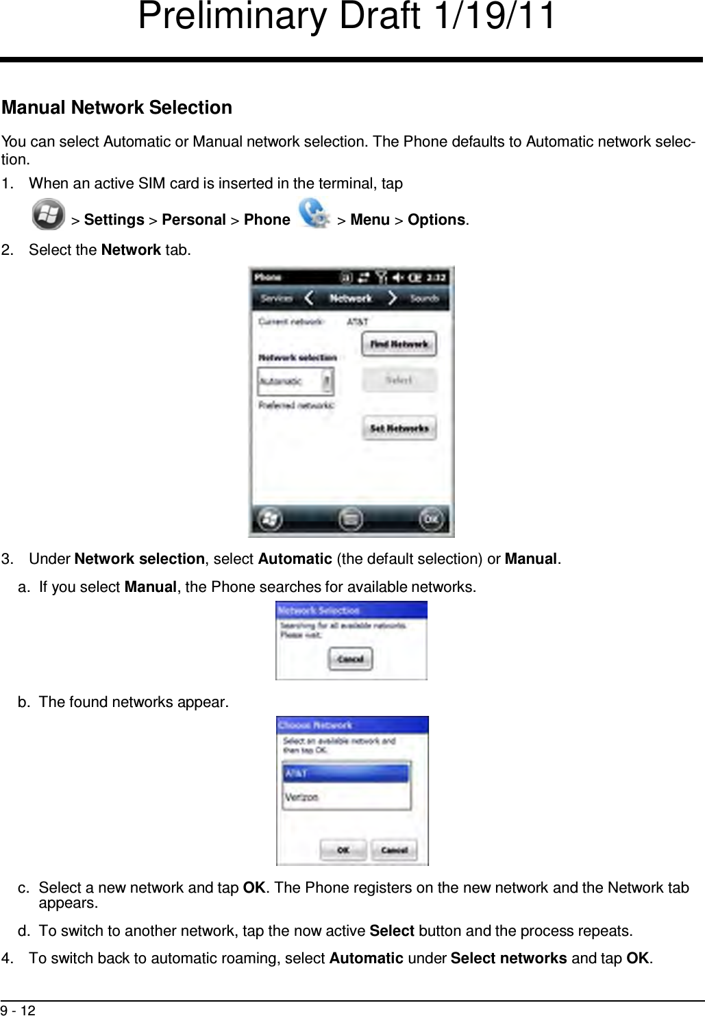
UserManual.wiki
>
Honeywell
>
99EXLW User Manual
>
User Manual
Contents
1.
User Manual 1 of 2
2.
user manual 2 of 2
3.
user manual 1 of 2
4.
User Manual
User Manual
Navigation menu
Upload a User Manual
Namespaces
Wiki Guide
HTML
PDF
Info
Views
User Manual
Discussion / Help
Navigation


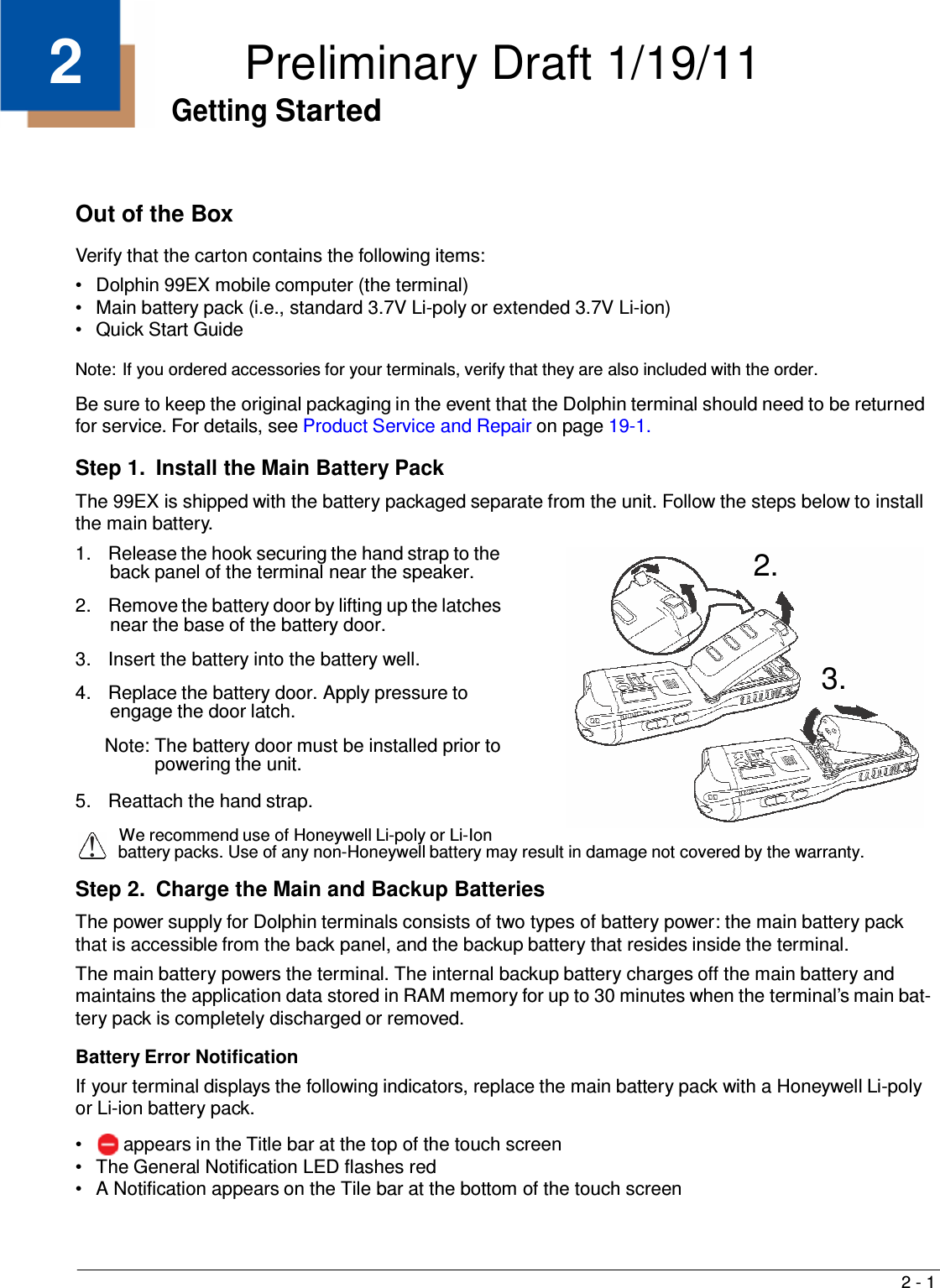
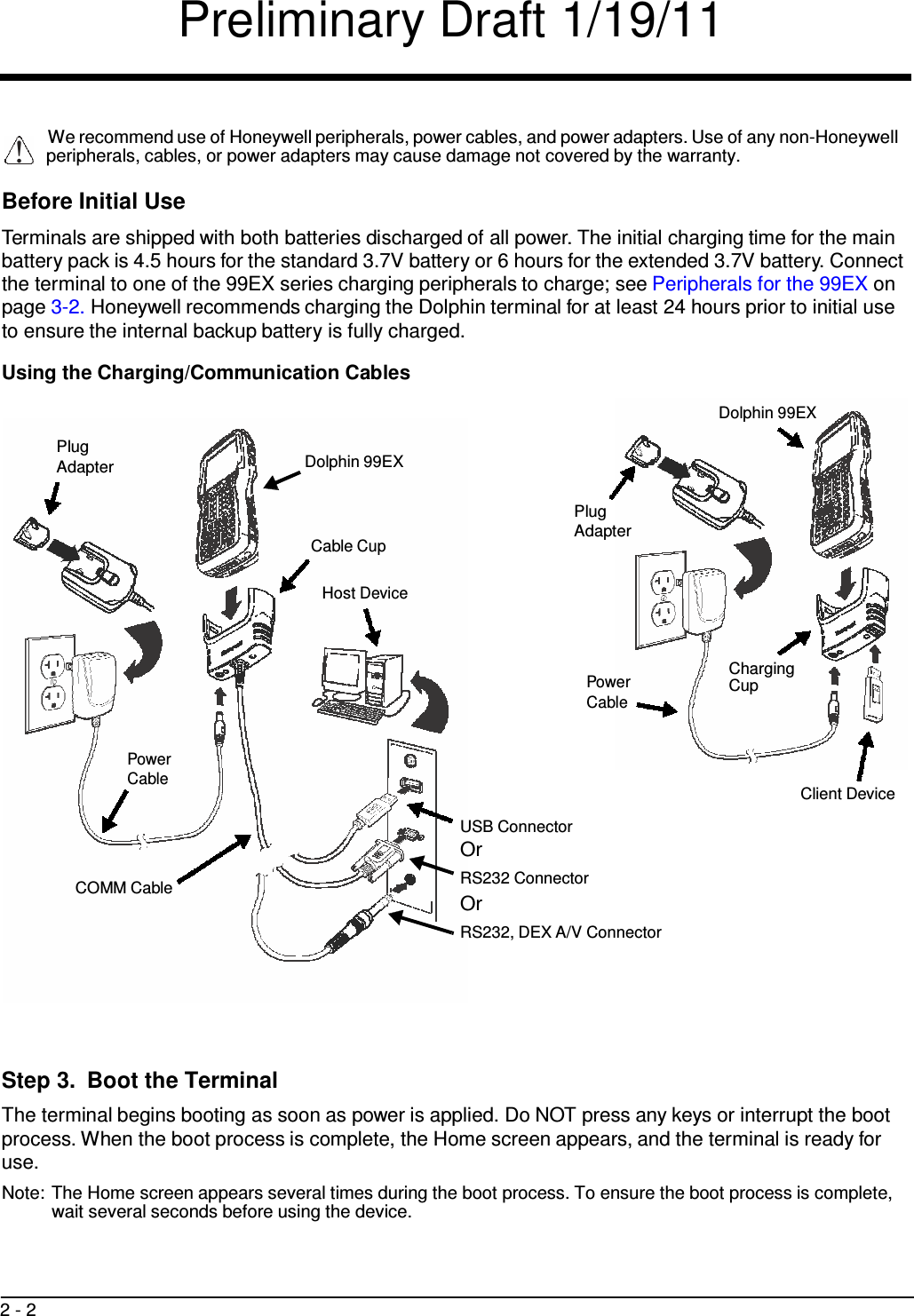

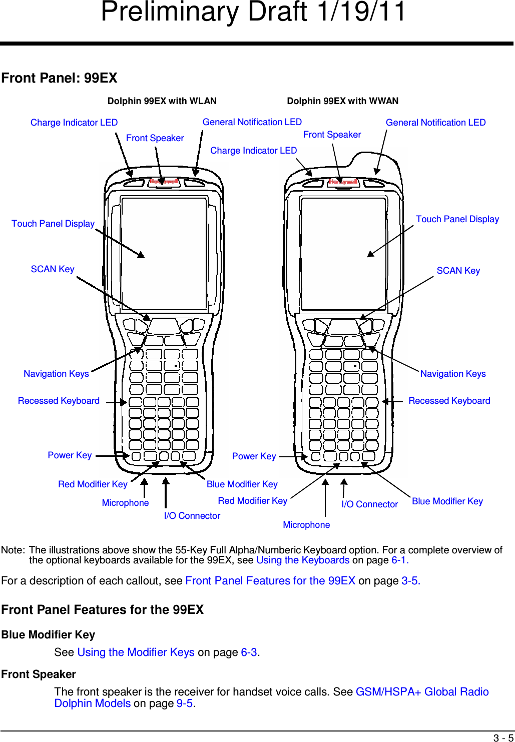
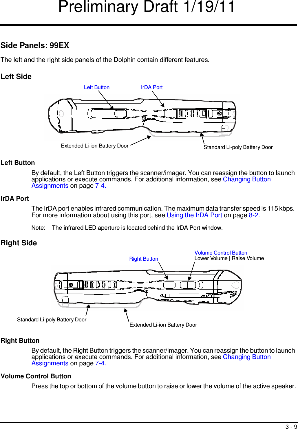
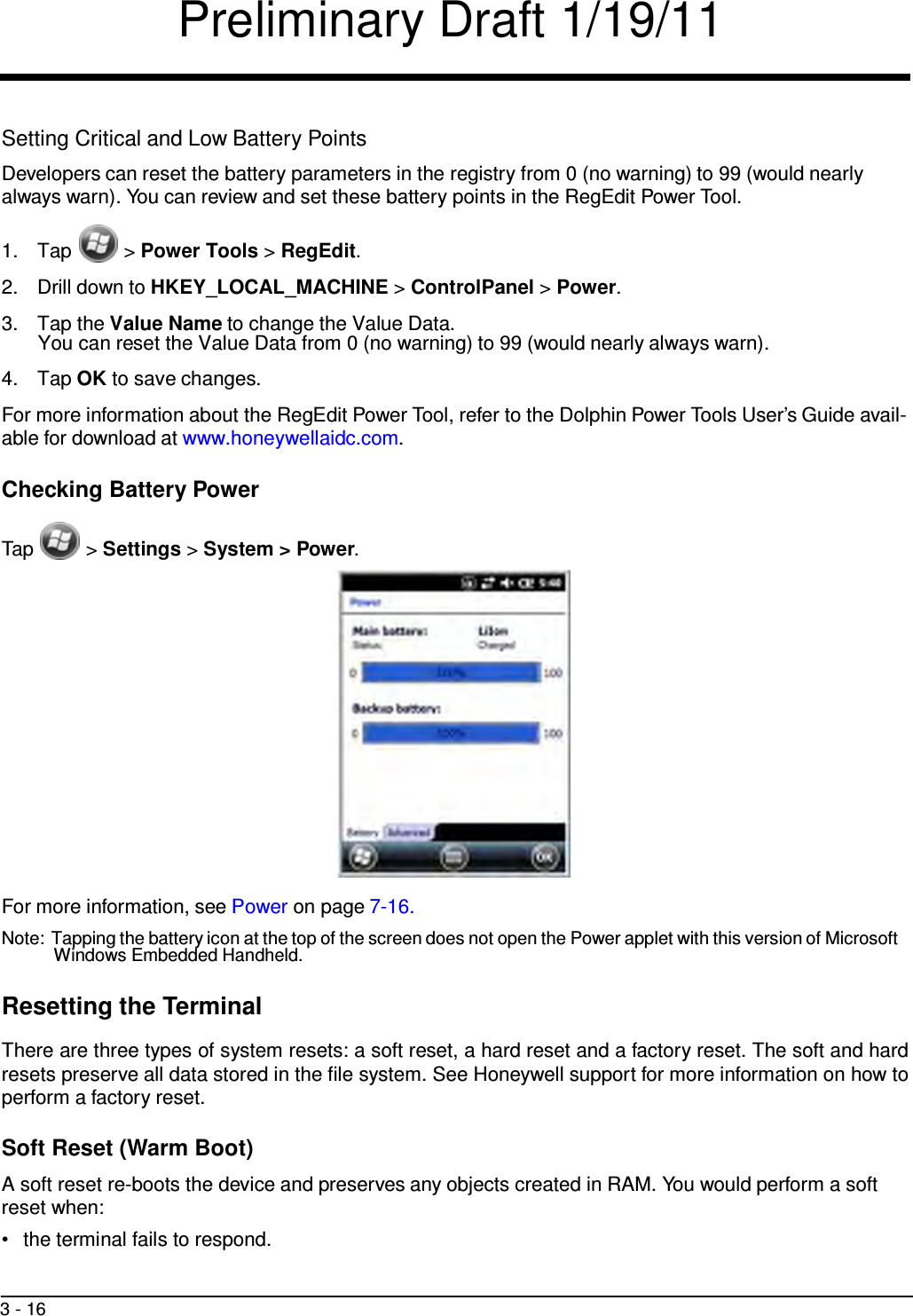
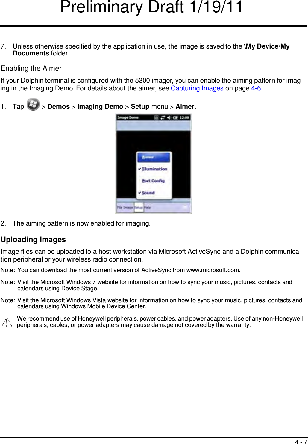
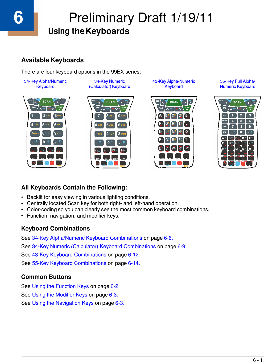
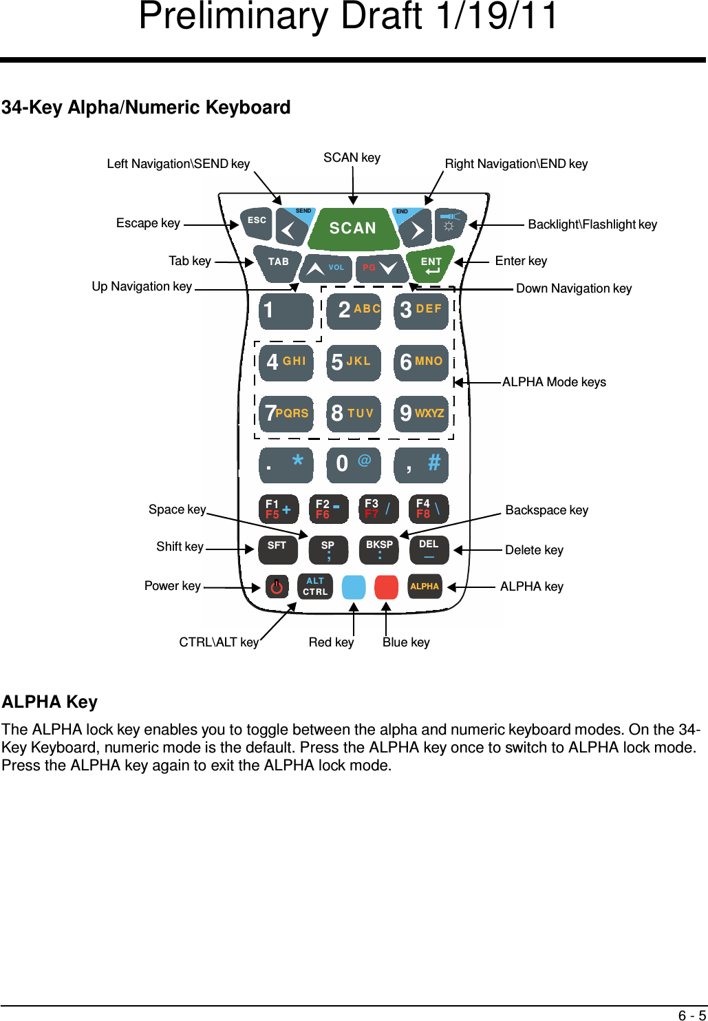
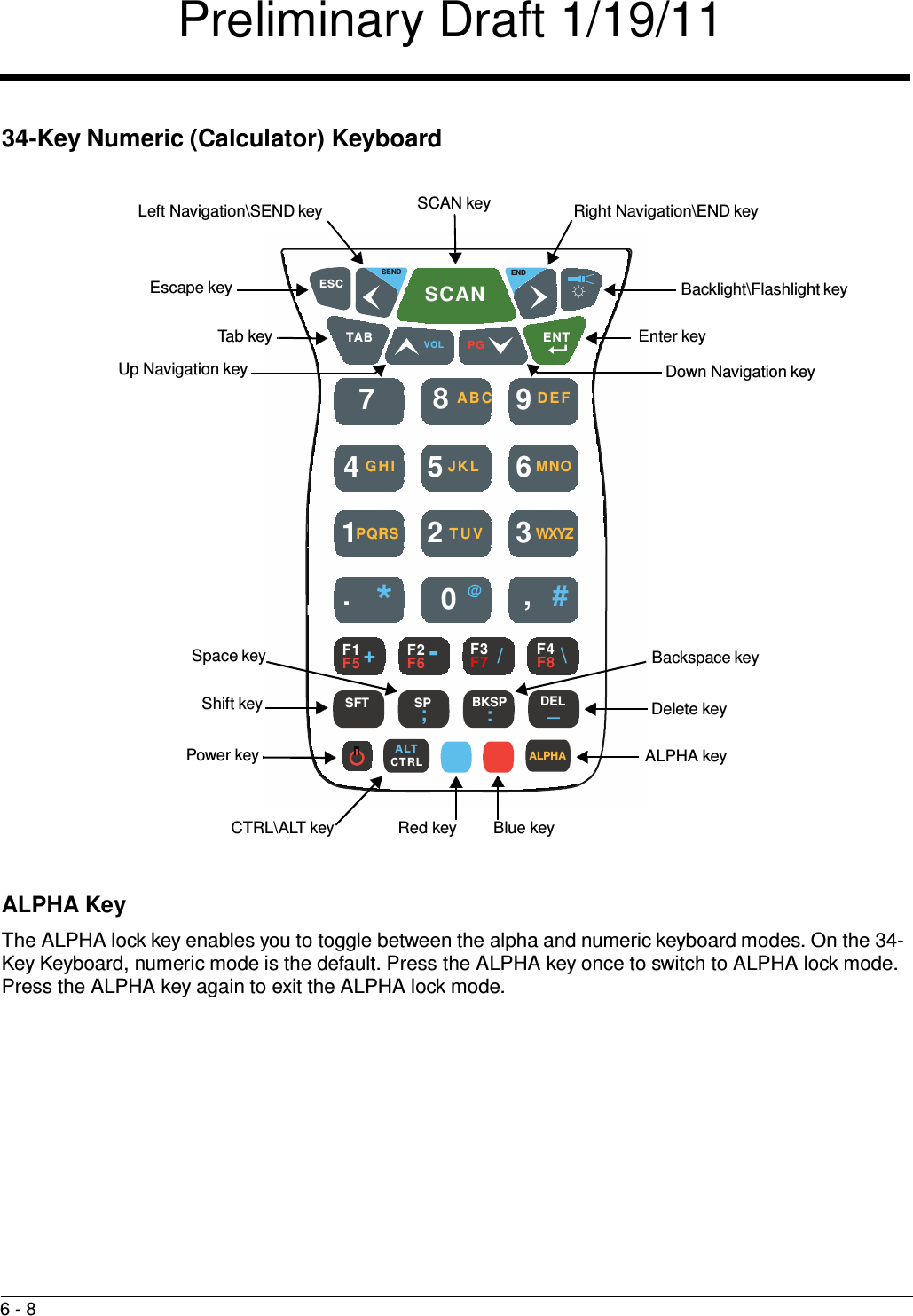
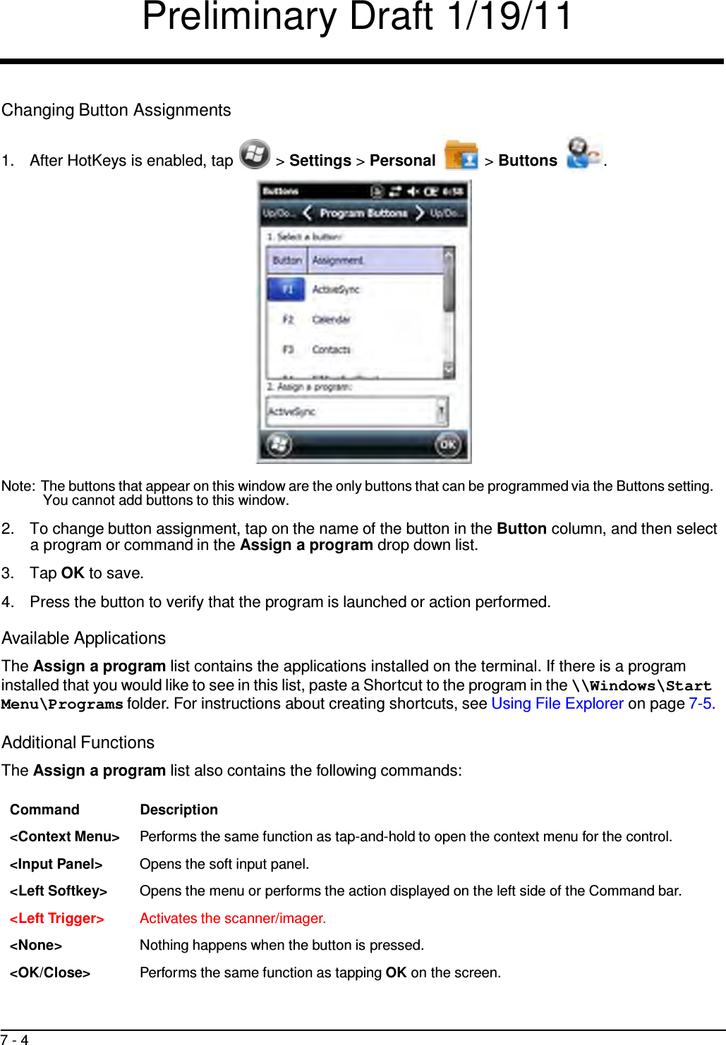
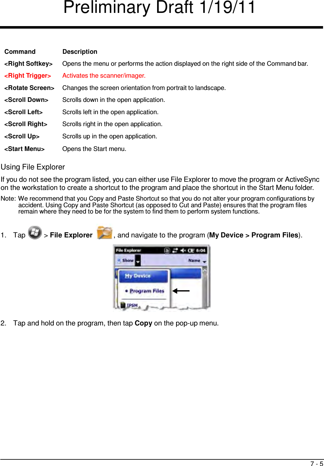
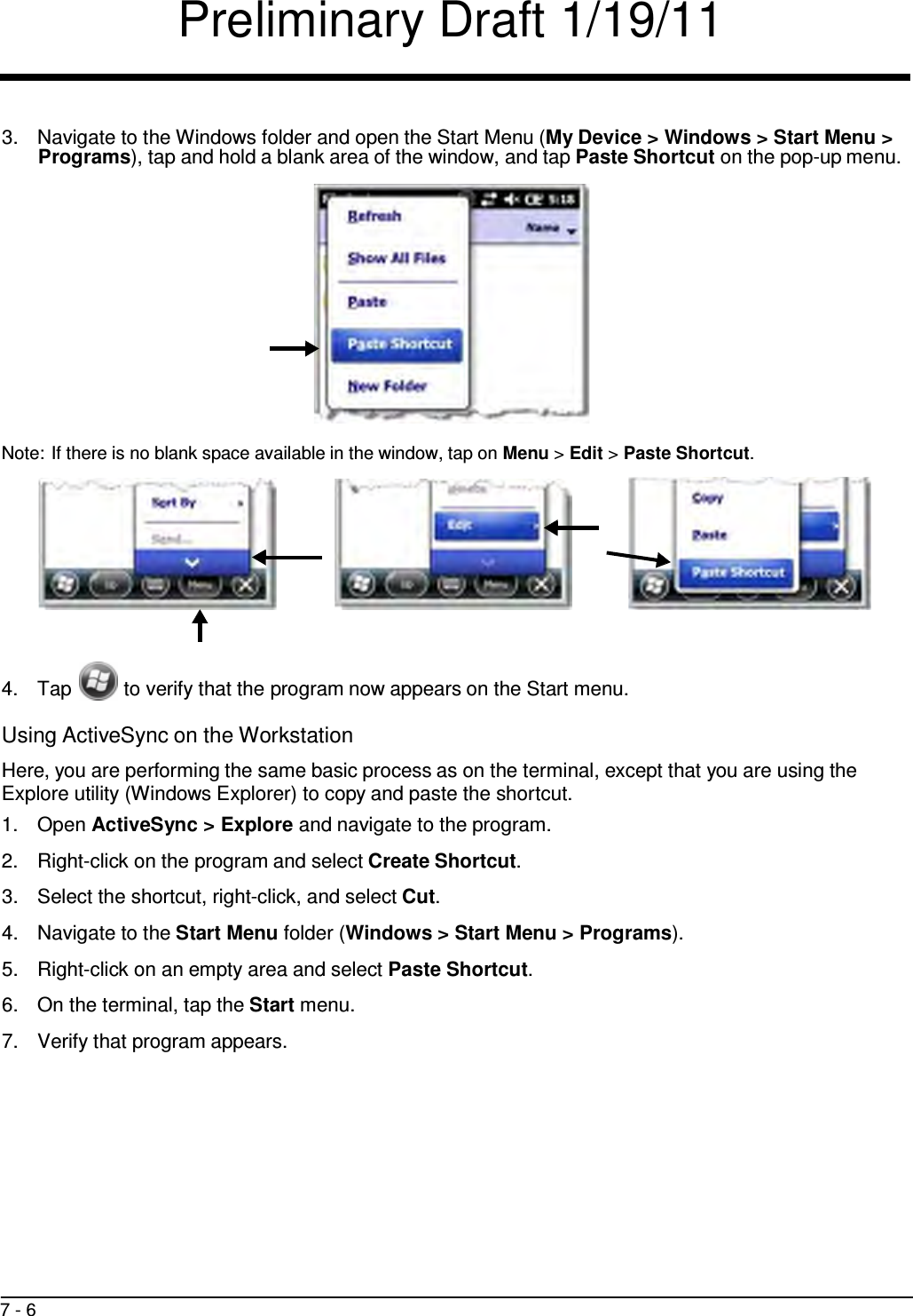
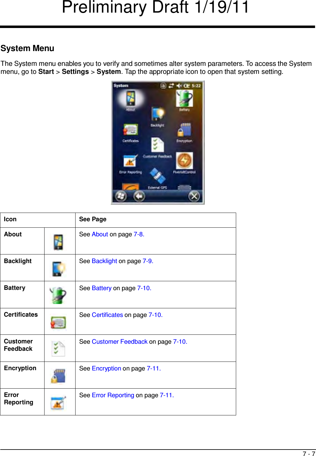
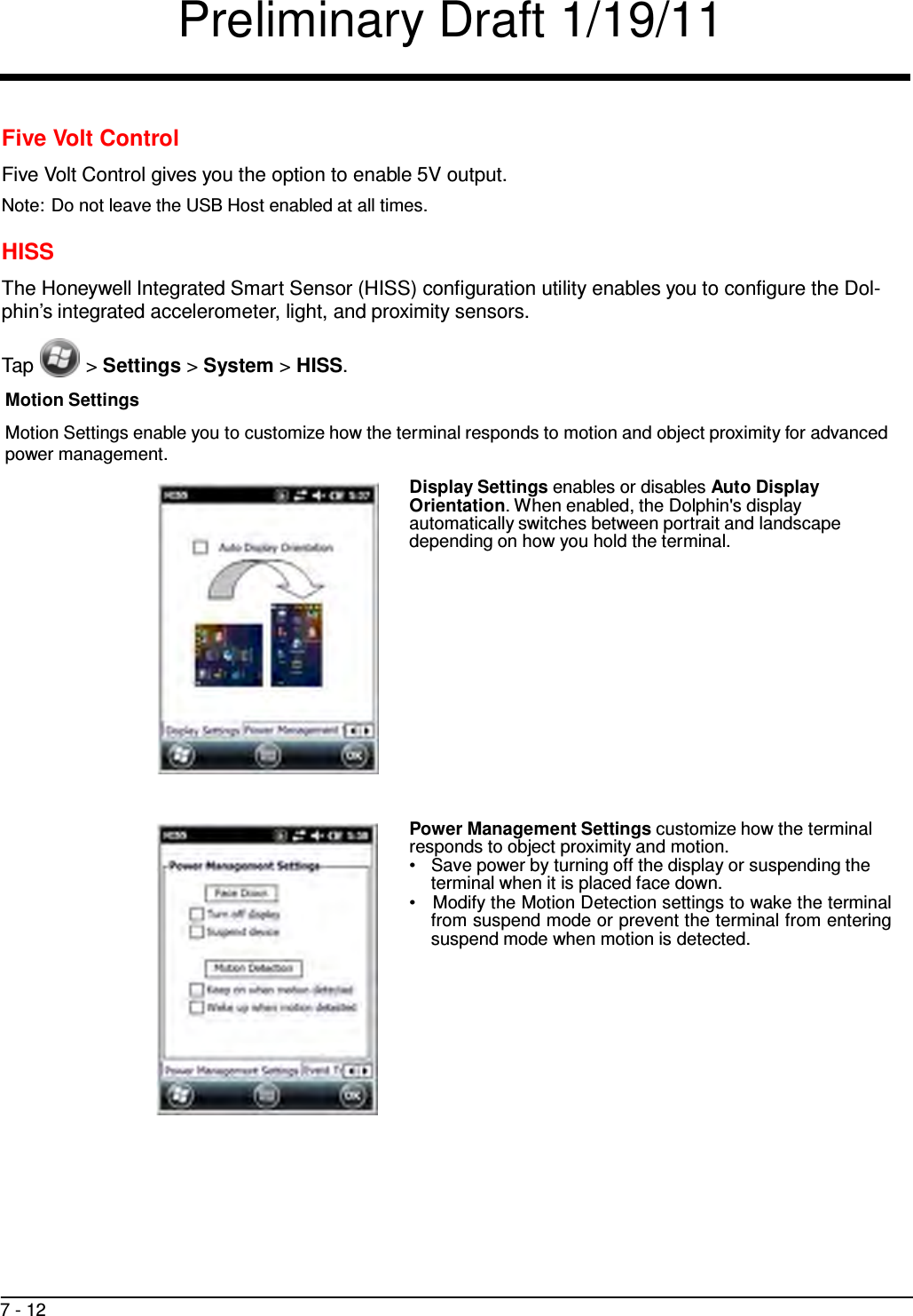
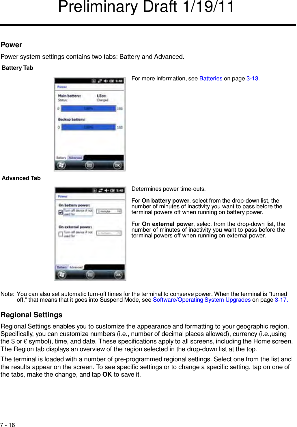
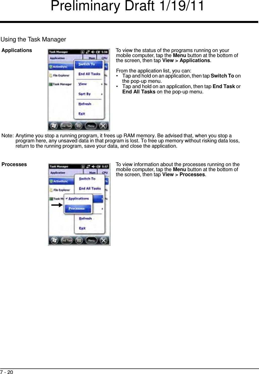
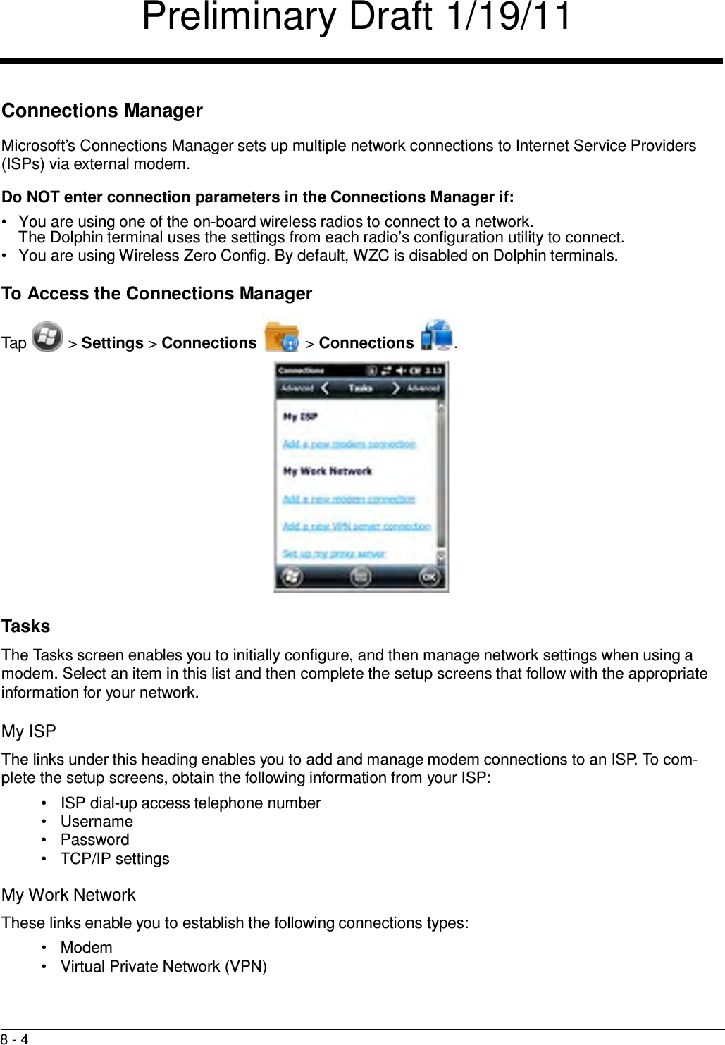
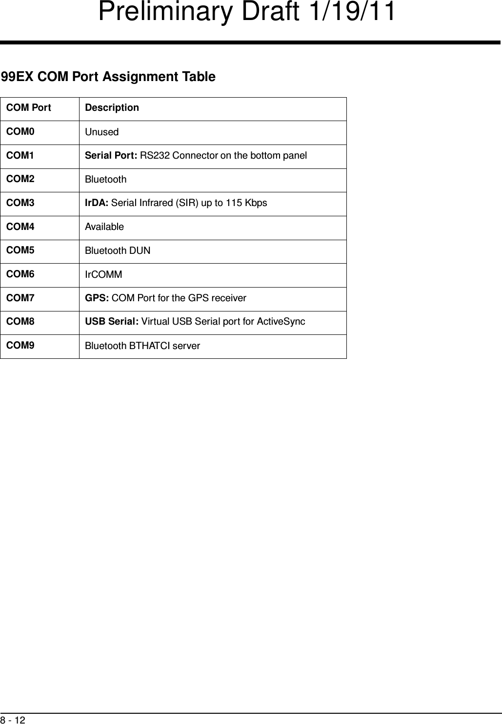
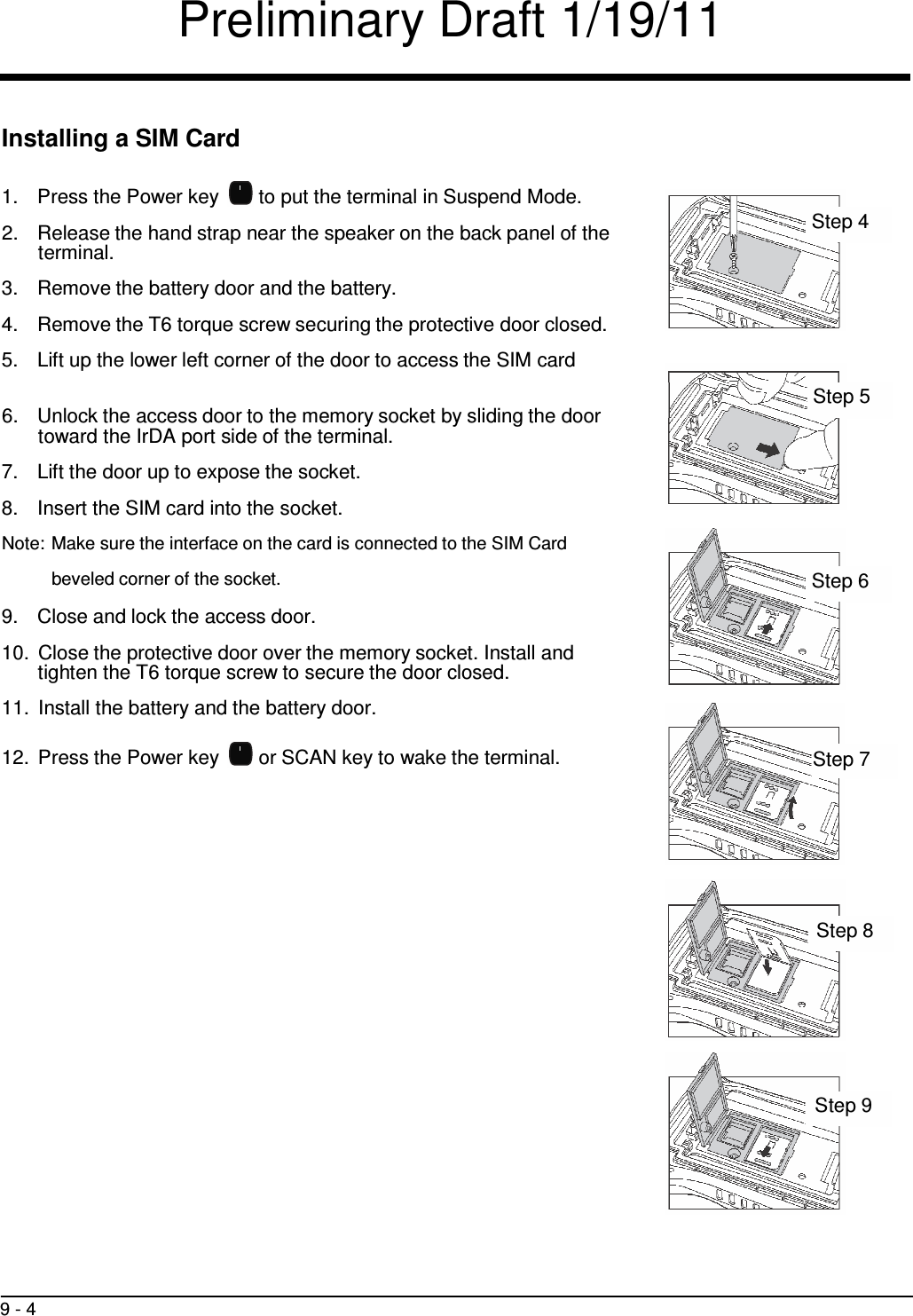
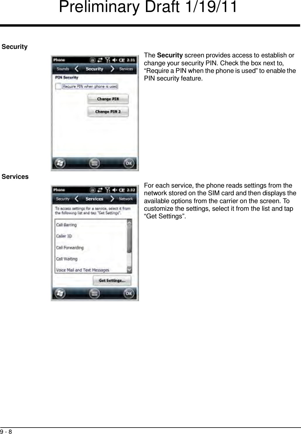
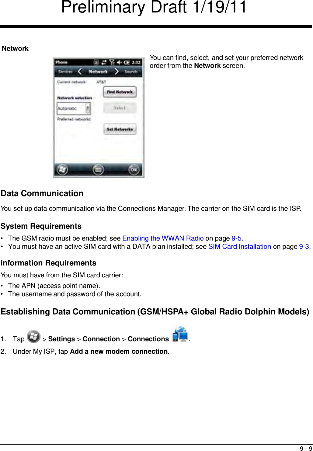
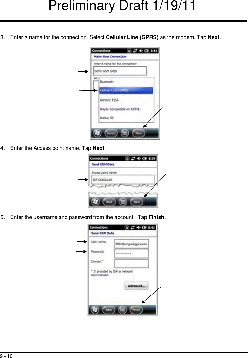
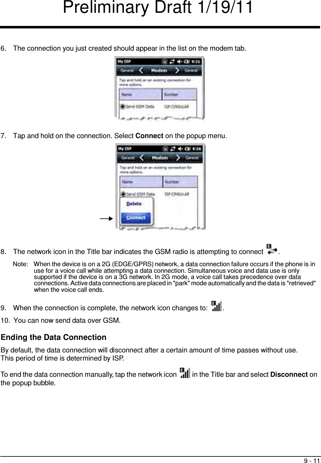
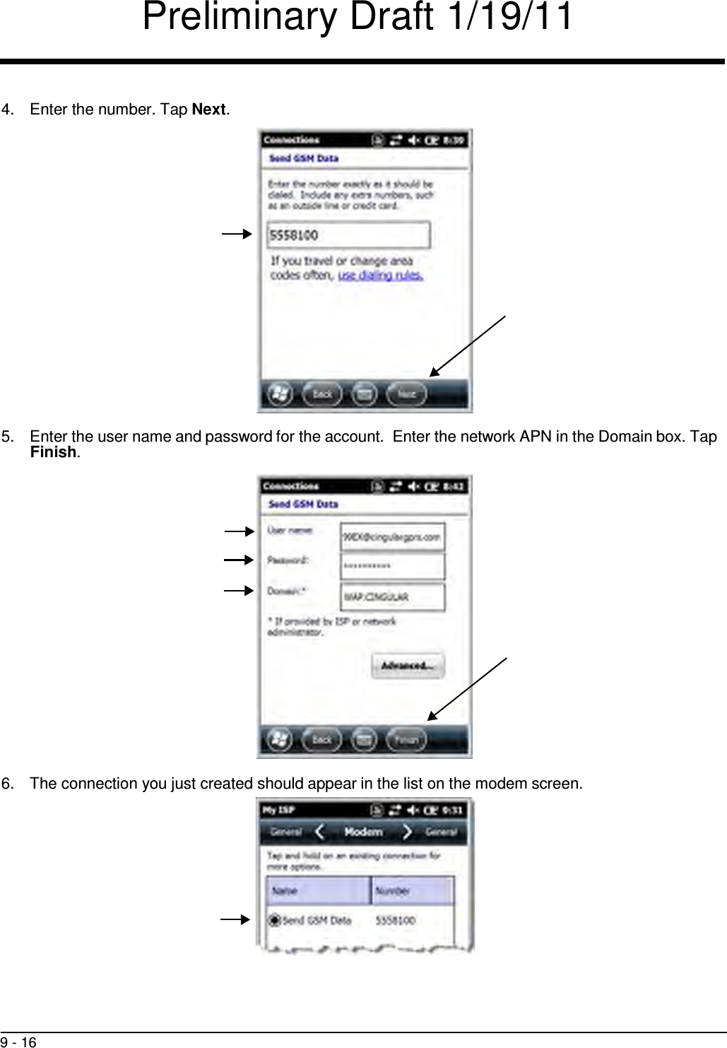
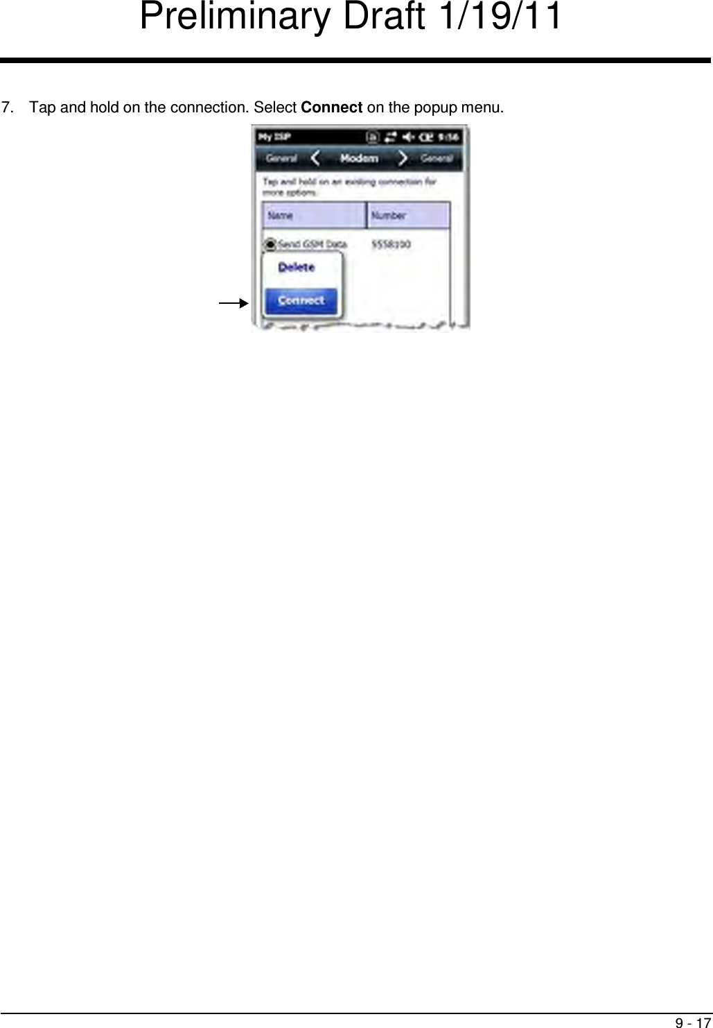
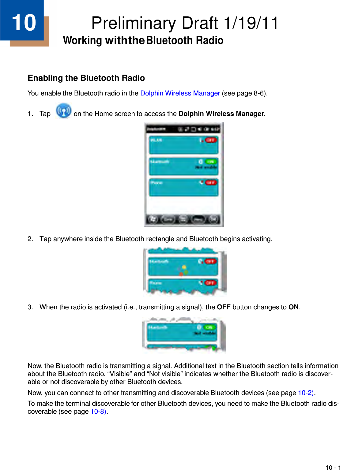
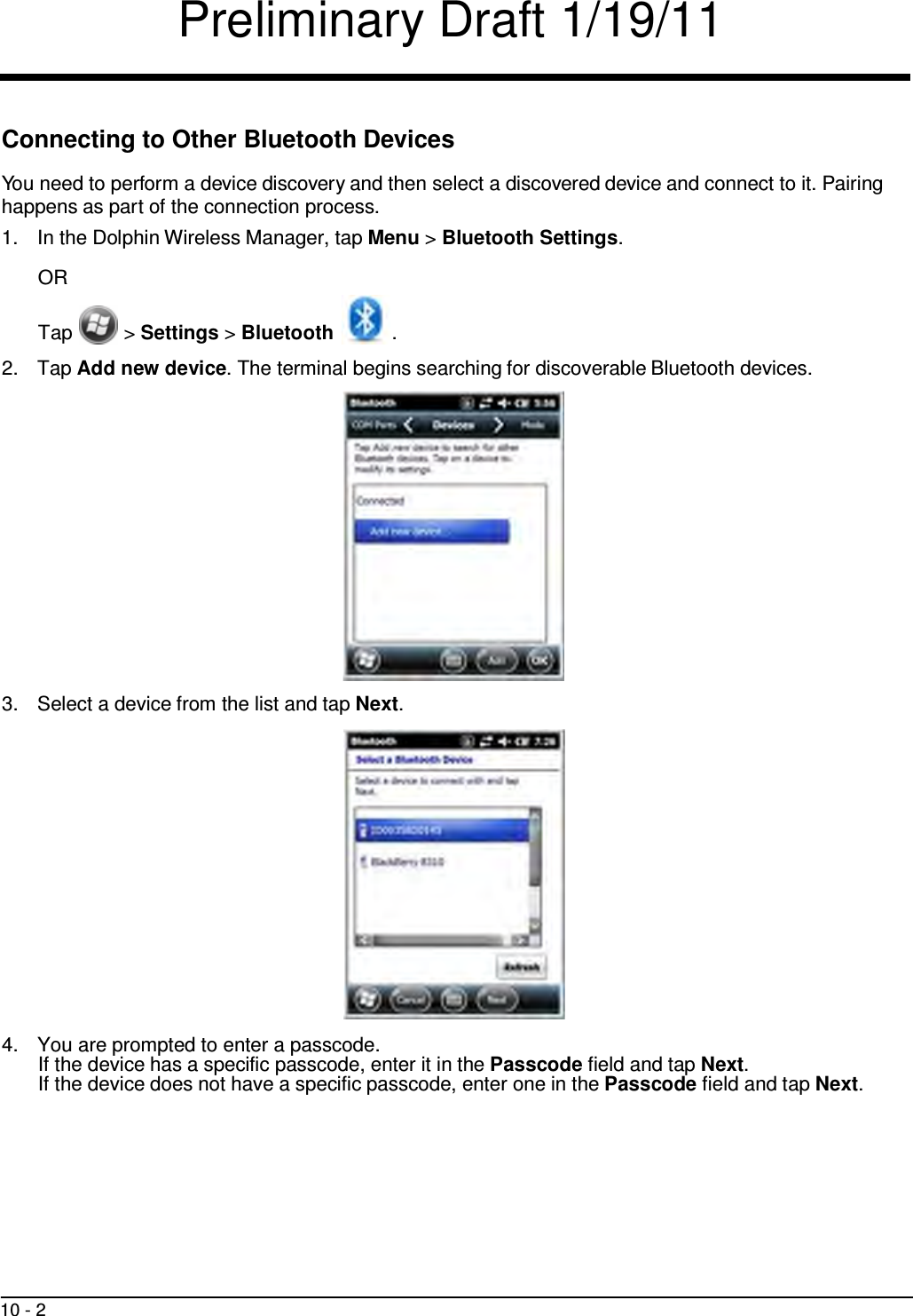
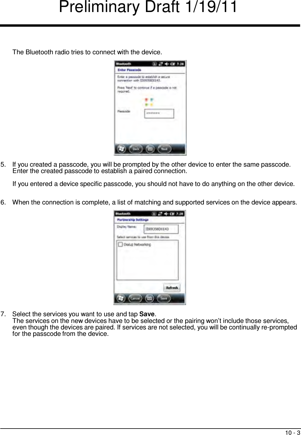
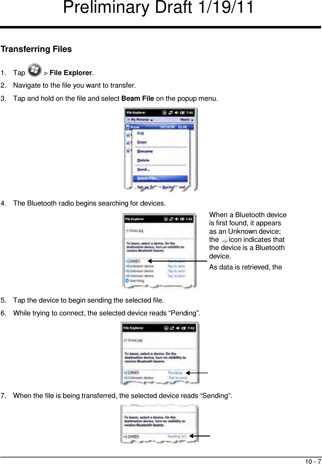
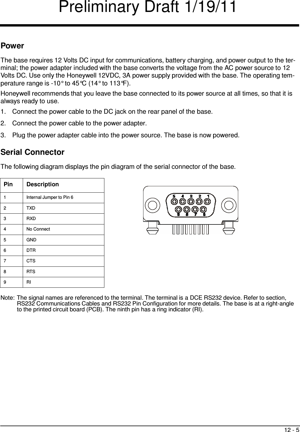
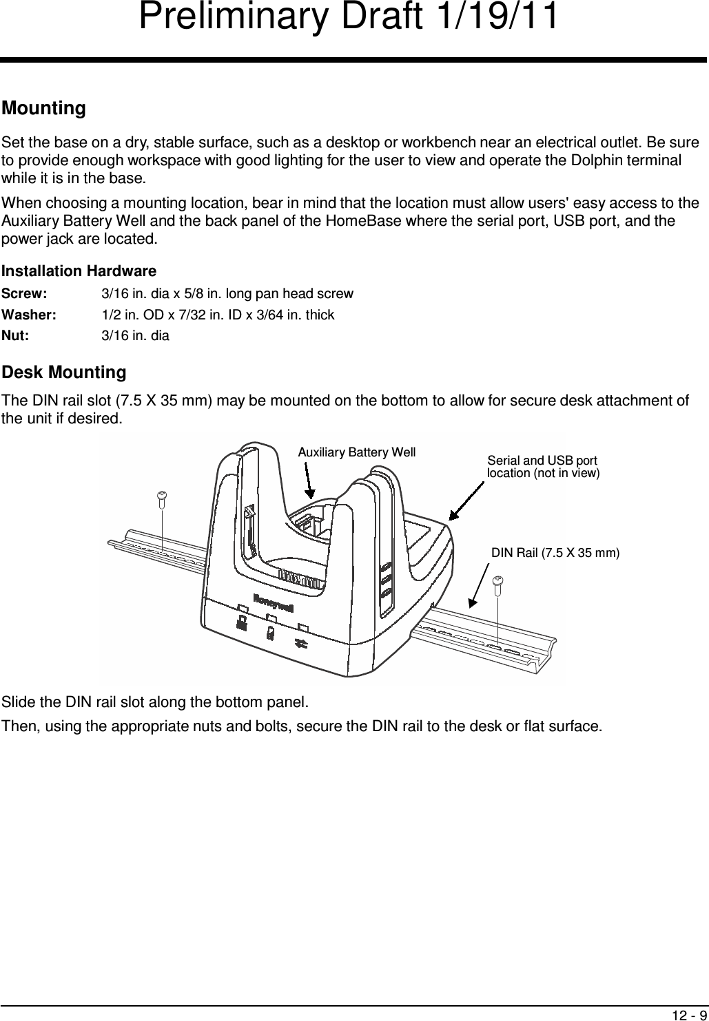
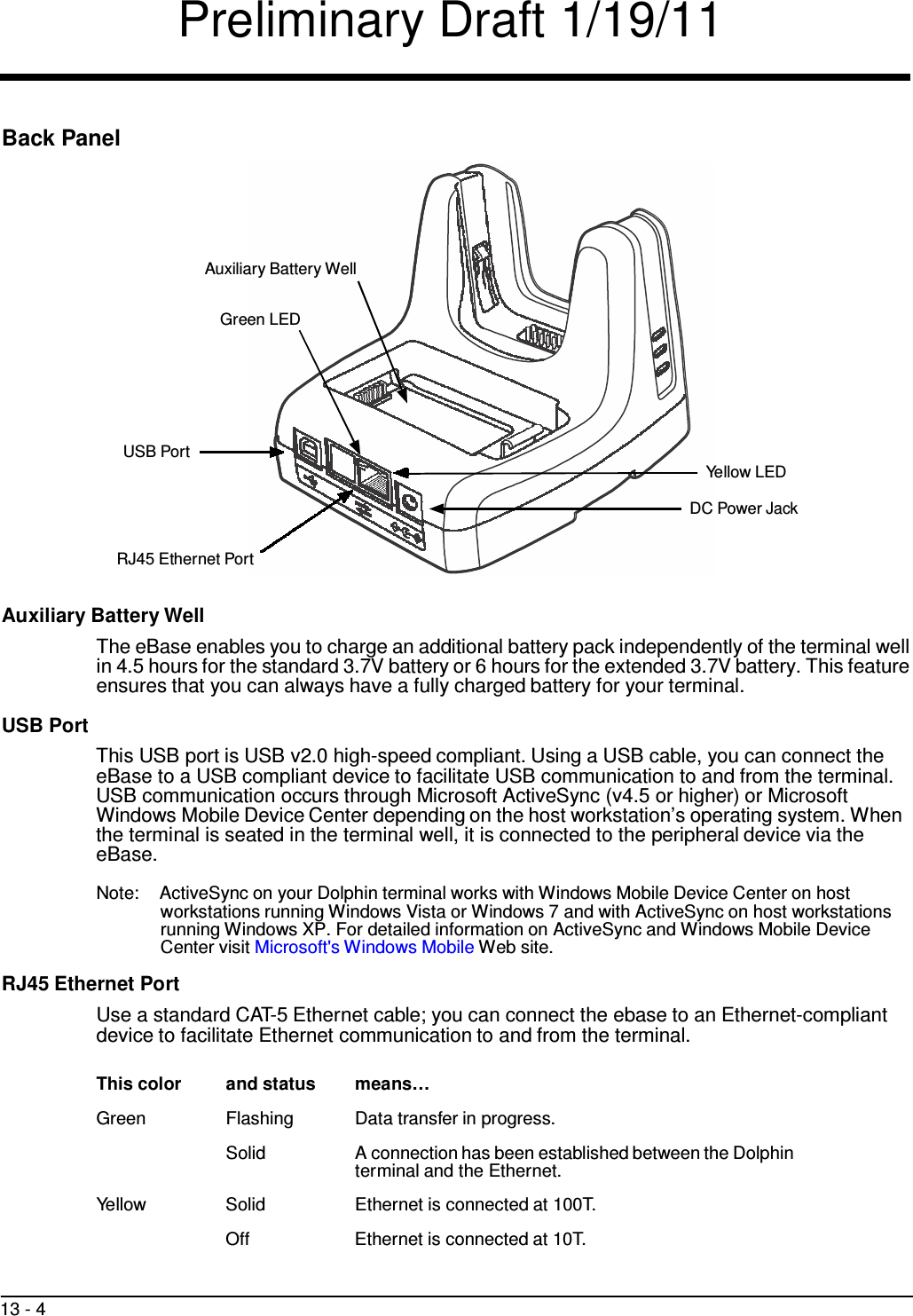
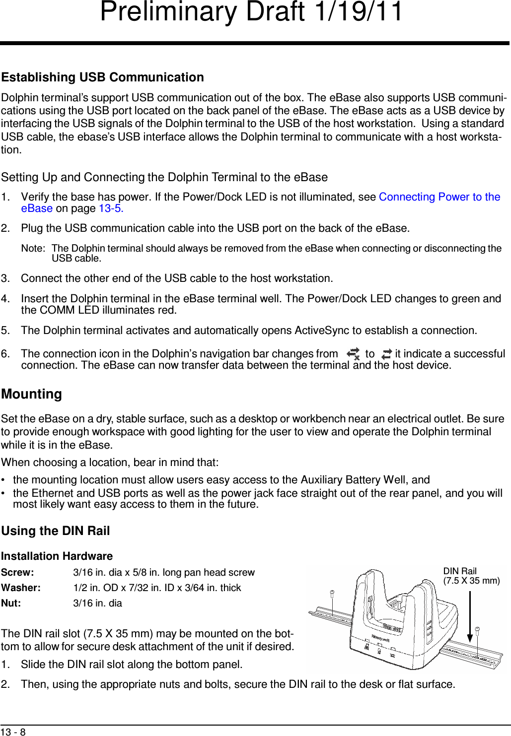
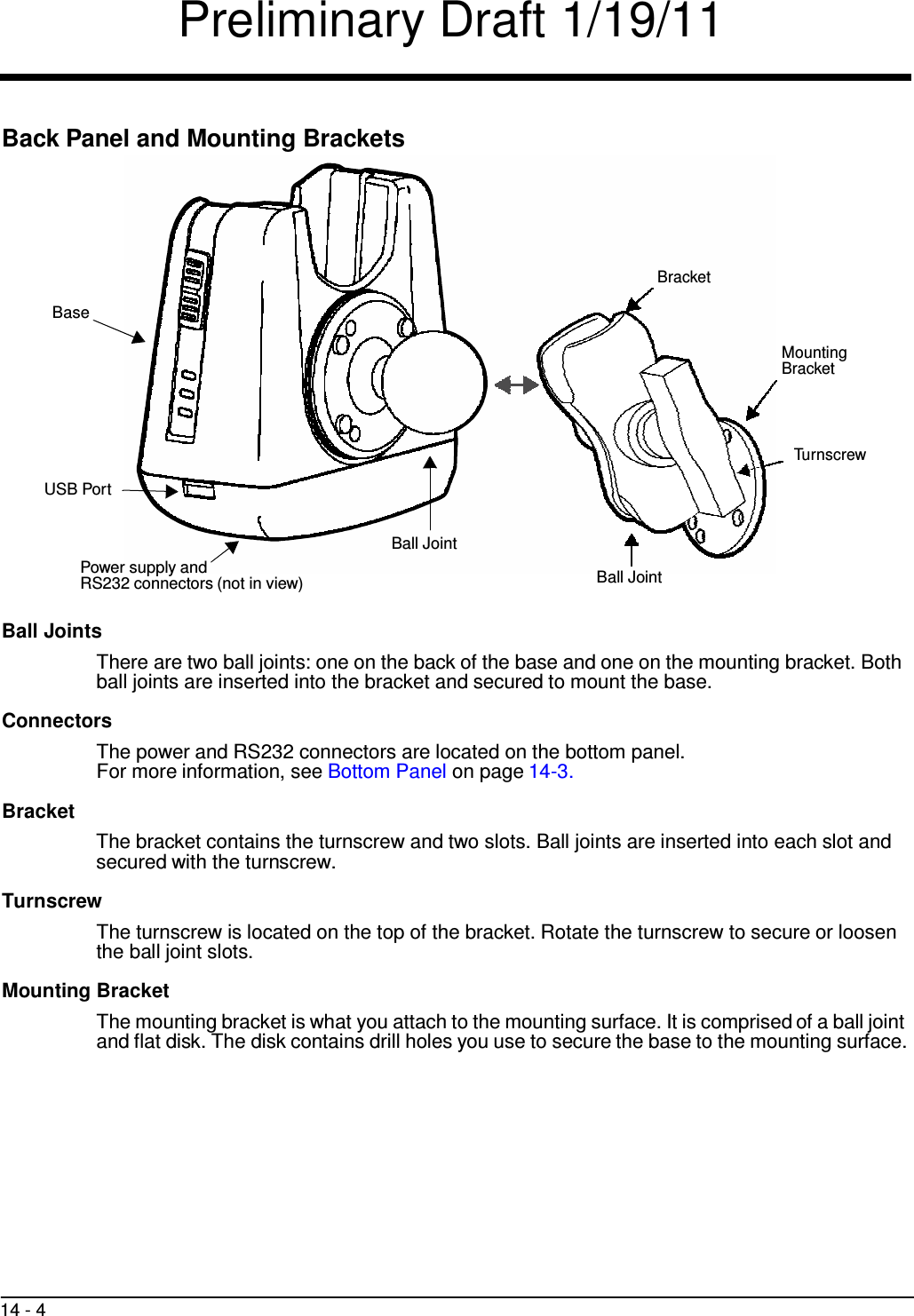
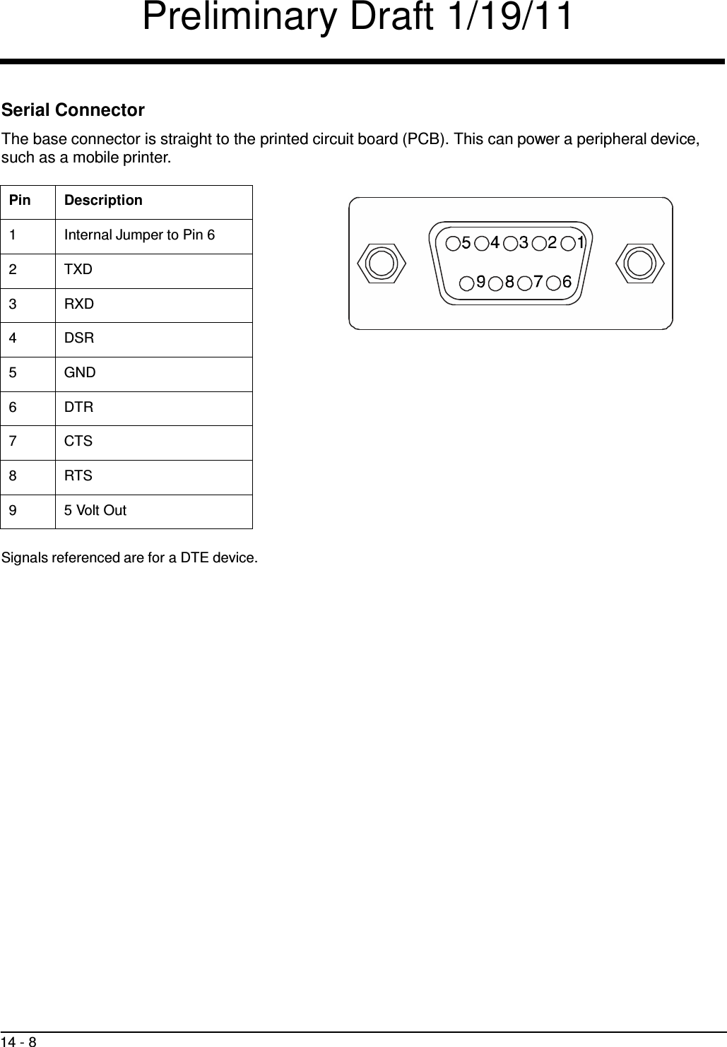
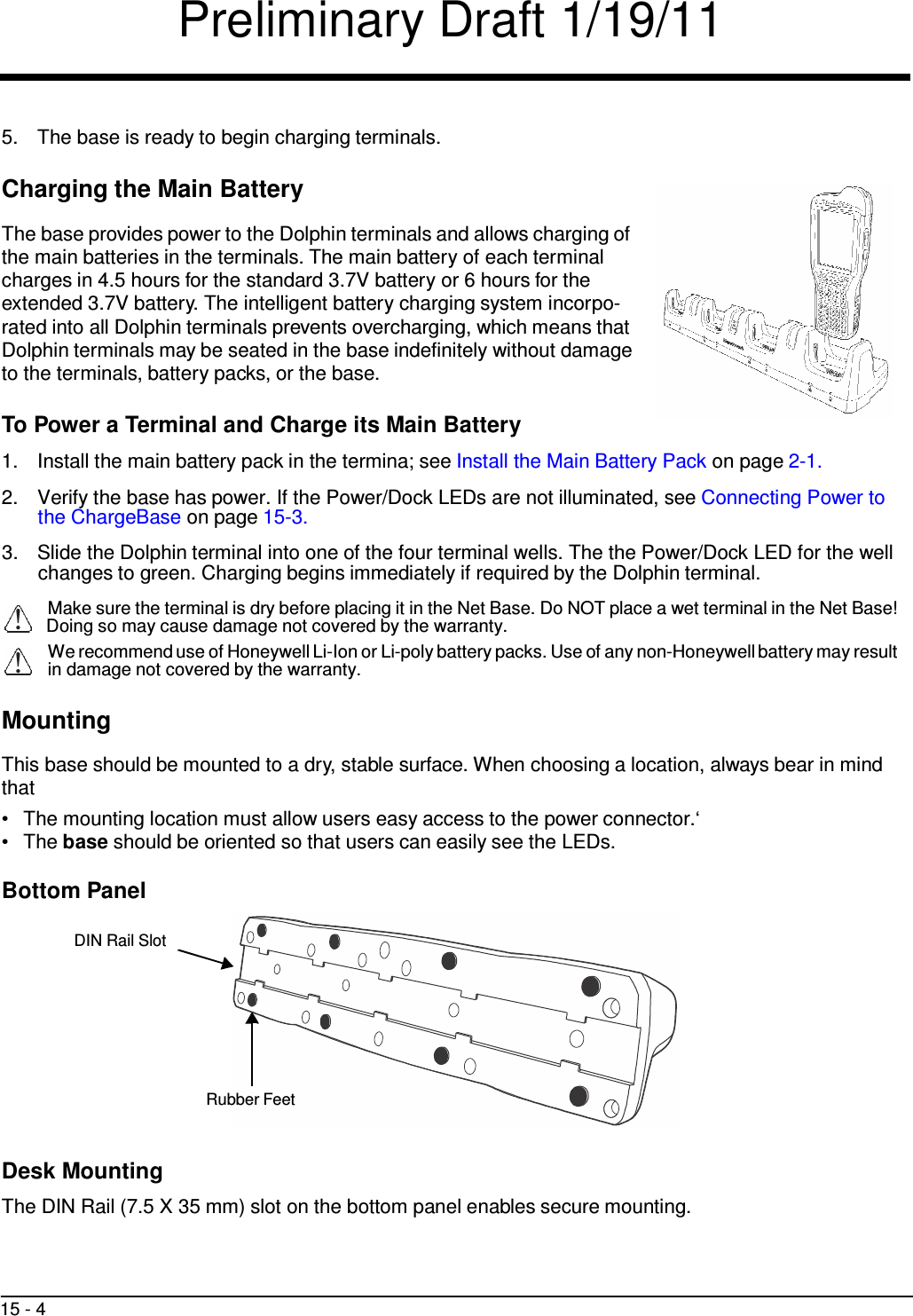
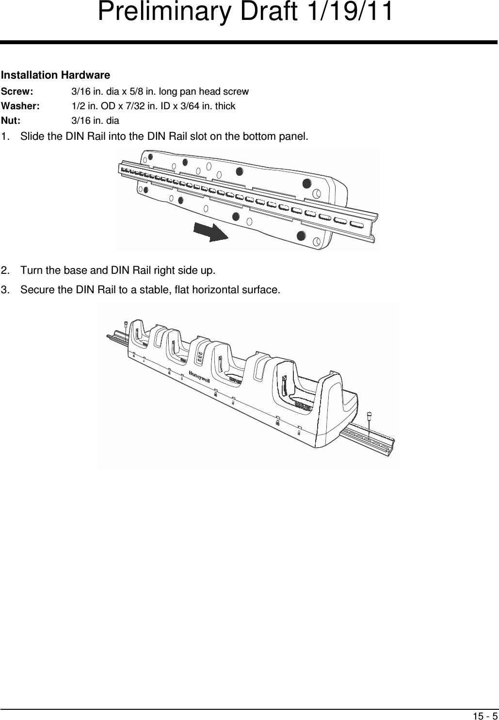
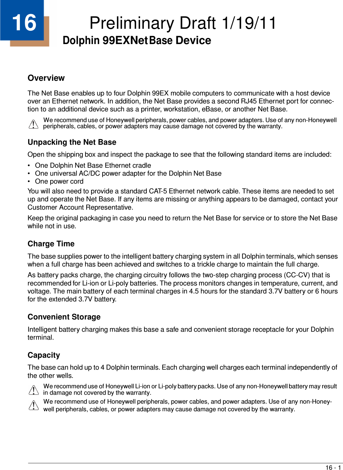
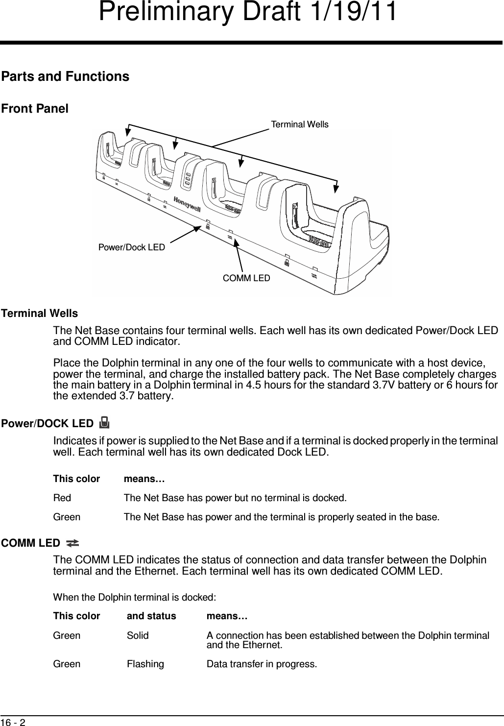
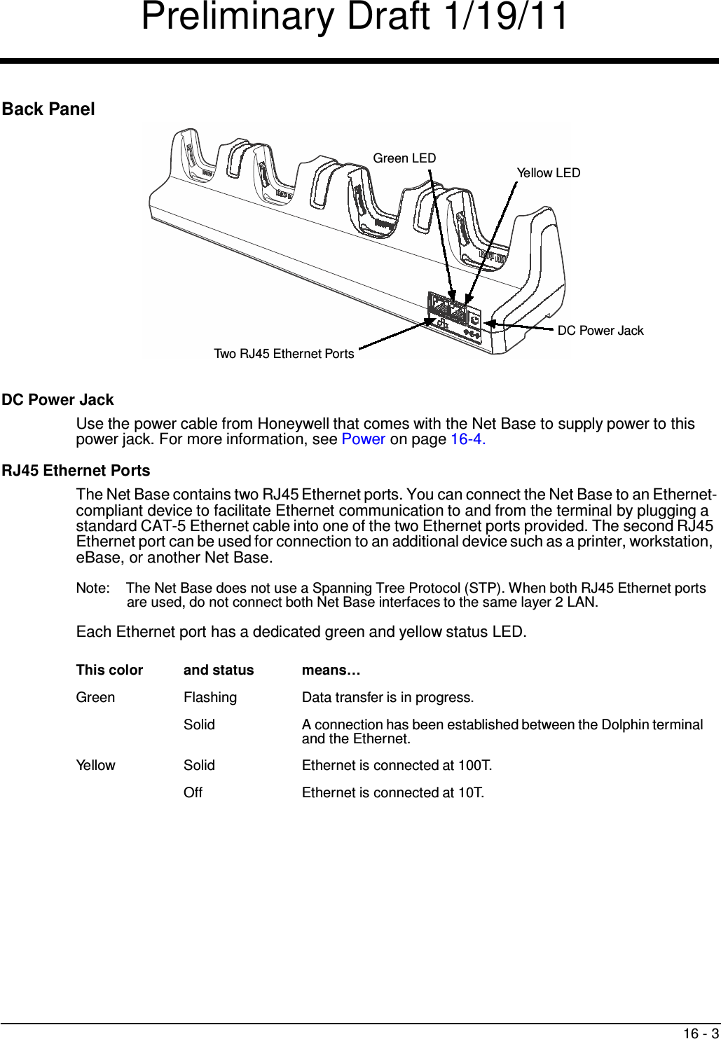
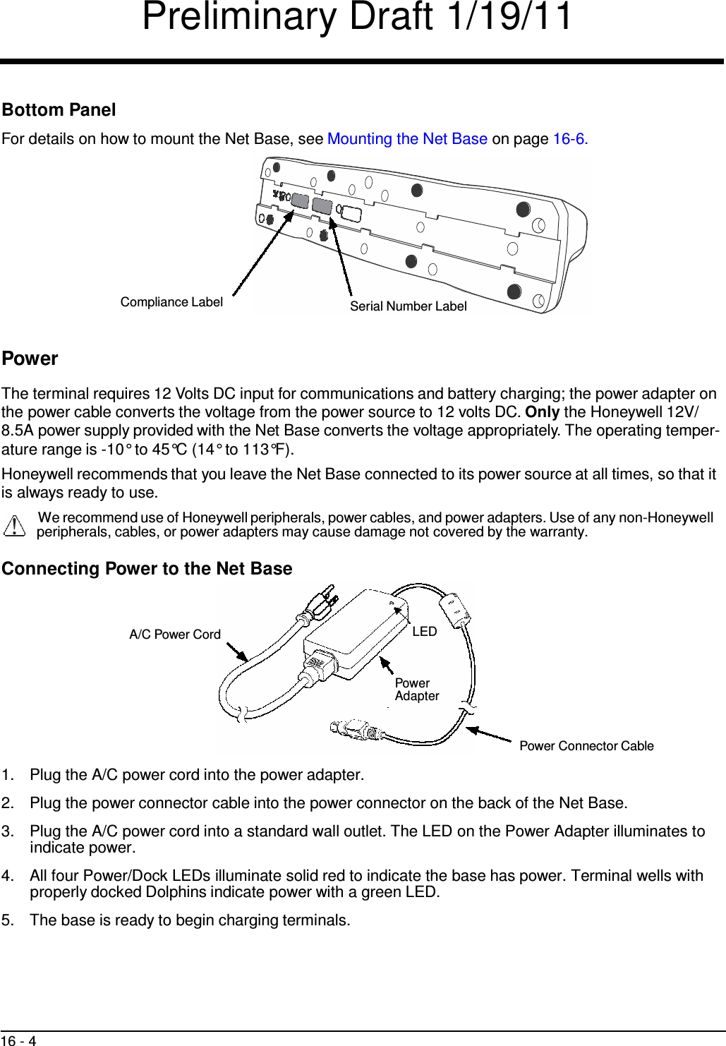
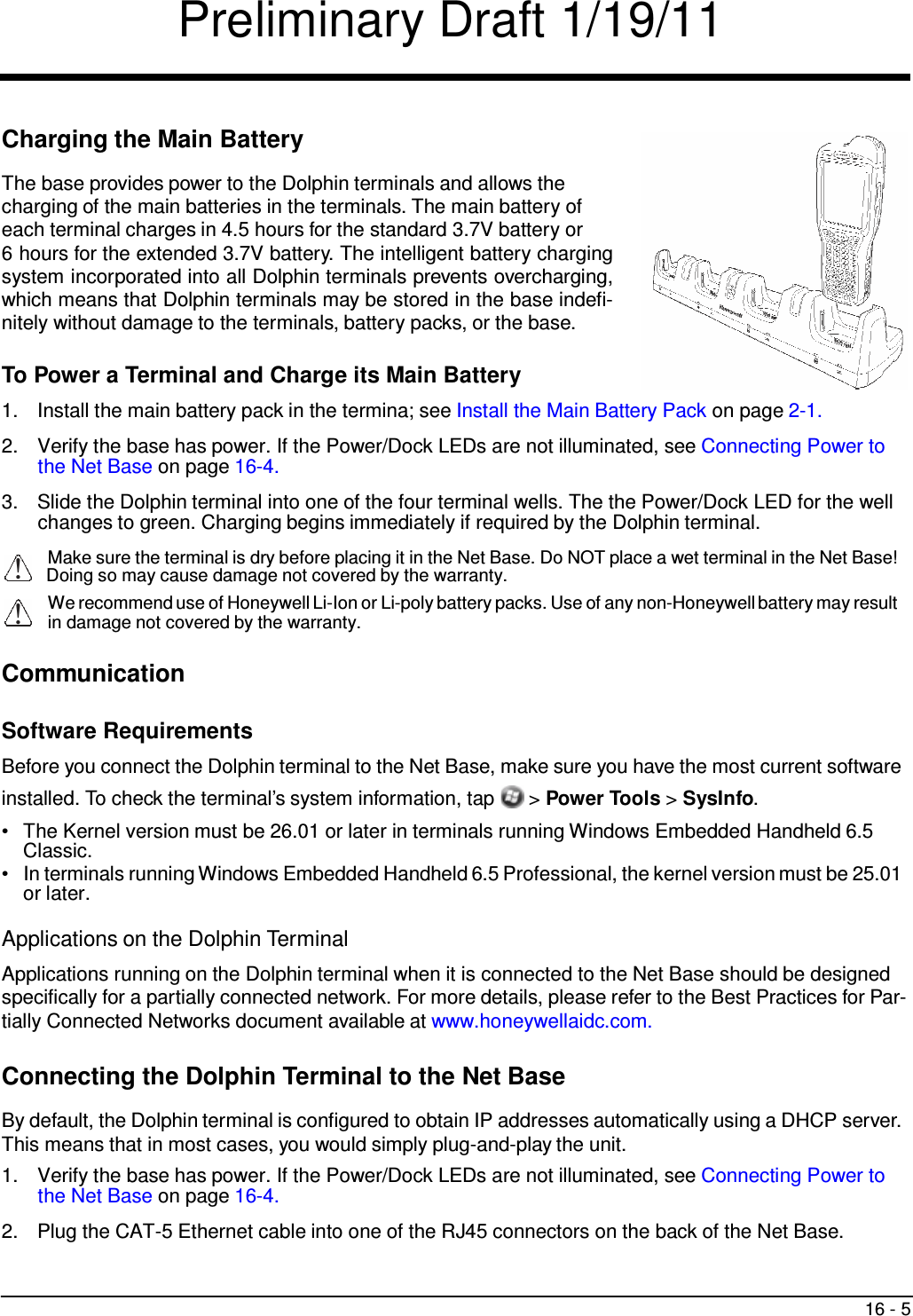
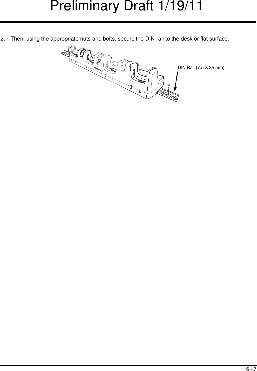
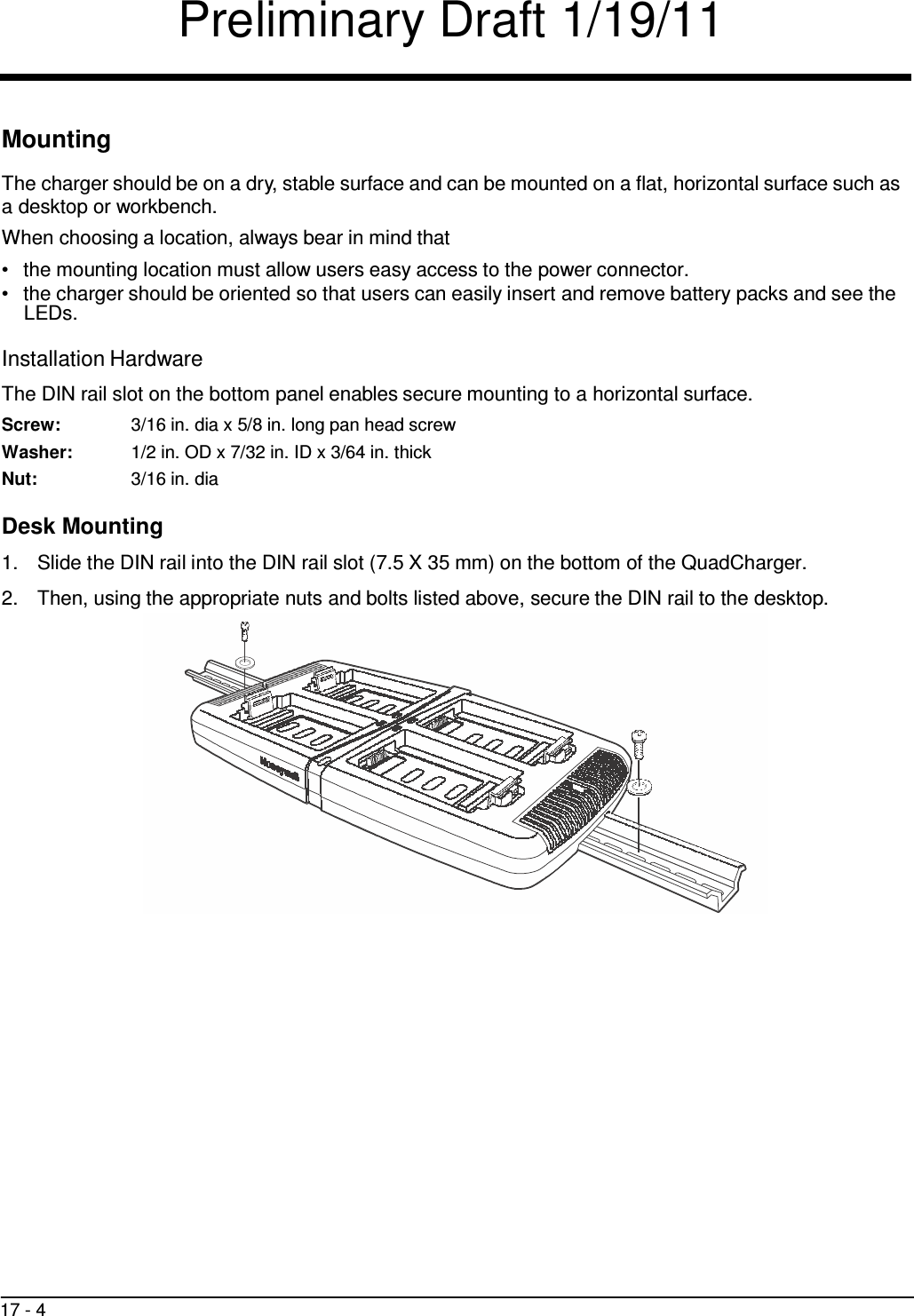
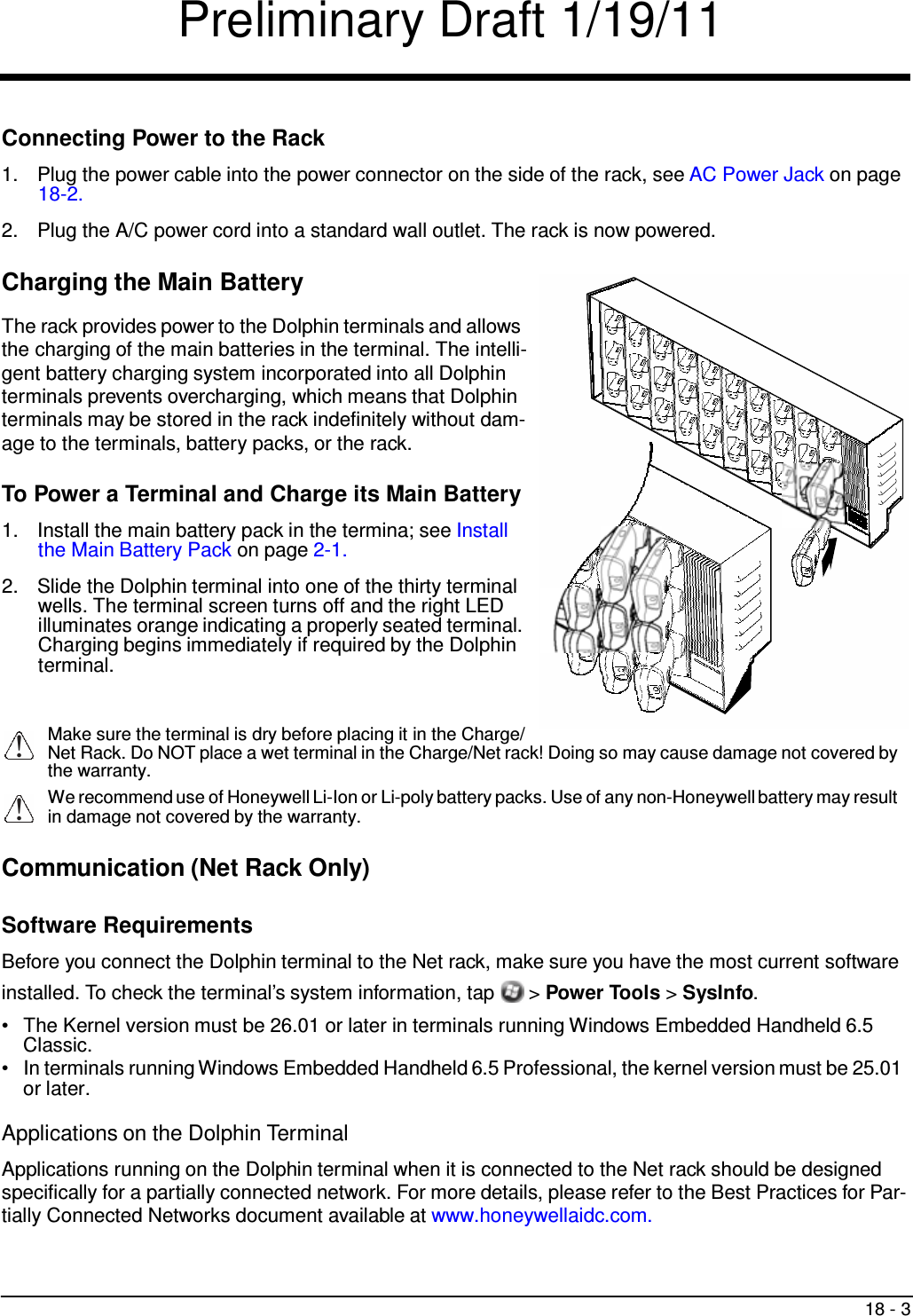
![Preliminary Draft 1/19/11 3 - 15 Charging The internal backup batteries are powered by the main battery pack. Therefore, charging the internal backup batteries require that the main battery pack be installed in the terminal and the terminal be con- nected to a charging device. Note: Honeywell recommends placing the terminal in Software/Operating System Upgrades (see page 3-17) before removing the battery cover. The internal backup battery must be fully charged before using the terminal for the first time. Honeywell recommends charging the Dolphin terminal for at least 24 hours prior to initial use to ensure the internal backup battery is fully charged. After that, if the internal backup battery becomes fully discharged of power, it requires a minimum of 30 hours of charging time to function normally. Guidelines for Use Follow these guidelines to maximize the life of the internal backup battery: • Keep a charged Li-ion or Li-poly battery pack in the terminal; the backup battery prematurely discharges if there is not at least a partially charged battery in the terminal. • Keep the terminal connected to power when the terminal is not in use. Managing Battery Power Letting the backup battery become fully discharged causes the terminal to lose all data in RAM. Honey- well recommends, you keep a charged battery pack in the terminal at all times to help prevent data loss. The internal battery discharges prematurely if there is not at least a partially charged battery in the termi- nal. When you remove a battery pack, insert another charged battery pack in the terminal immediately. Default Critical and Low Battery Points When the terminal is running on battery power (as opposed to external power), warnings are displayed when the battery reaches critical and low battery points. The warning points are determined by the fol- lowing registry entry: [HKEY_LOCAL_MACHINE\ControlPanel\Power] There are two DWORD values in this registry entry: MedState and LowState. The default values for these entries are as follows: MedState=25% This sets the Low Battery point to 25%. When the battery hits the percentage charge specified here, the user is notified. LowState=10% This sets the Critical Battery point to 10%. When the battery hits the percentage charge specified here, the user is notified. Note: Warnings do not appear when the terminal is on external power.](https://usermanual.wiki/Honeywell/99EXLW.User-Manual/User-Guide-1536797-Page-41.png)