Honeywell 99EXLW 99EX Mobile computer User Manual 2 of 2
Honeywell International Inc 99EX Mobile computer 2 of 2
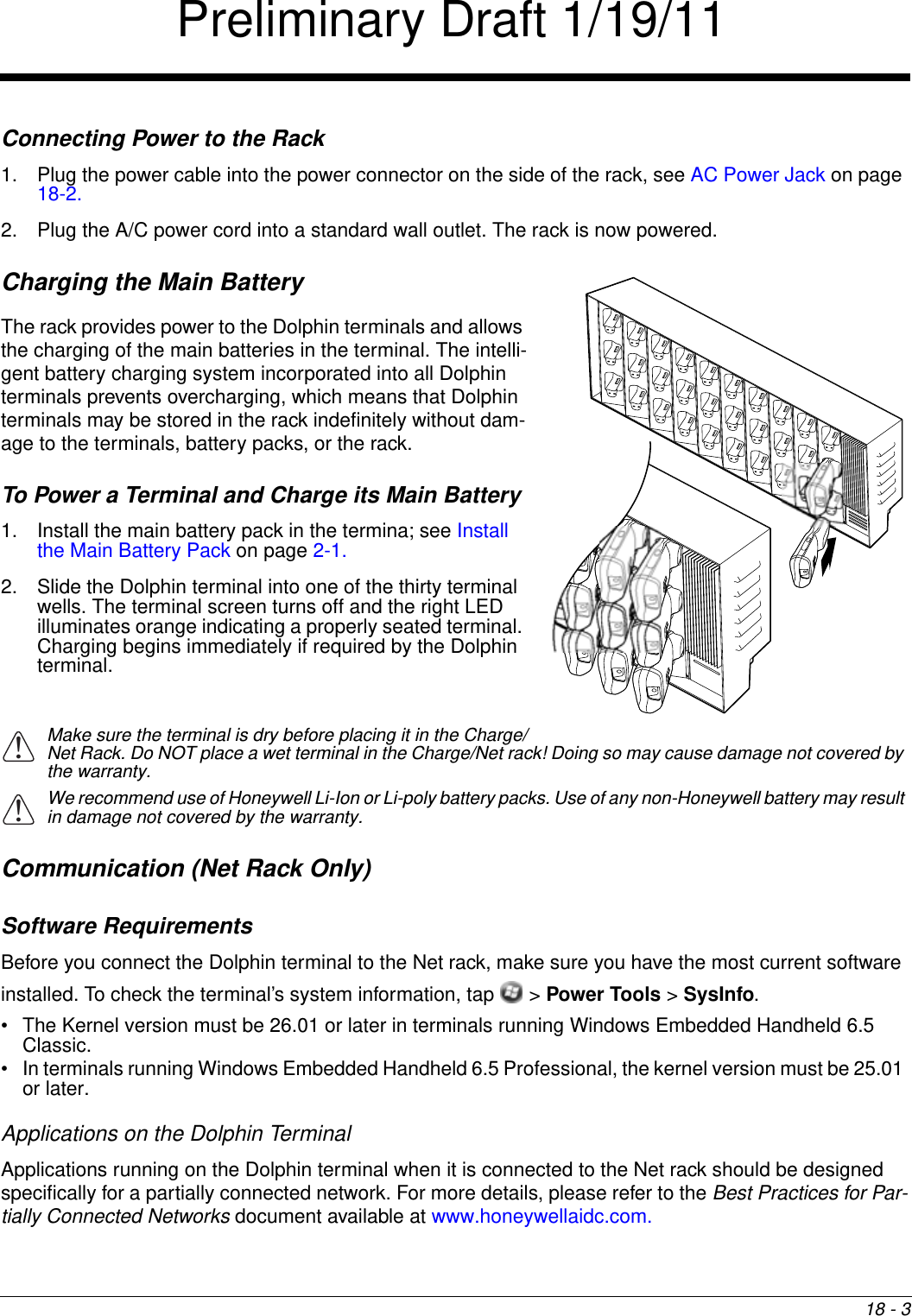
UserManual.wiki
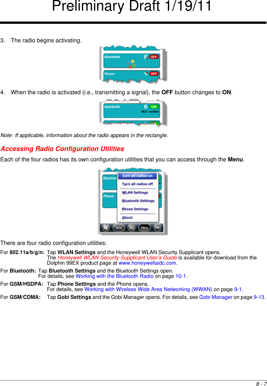
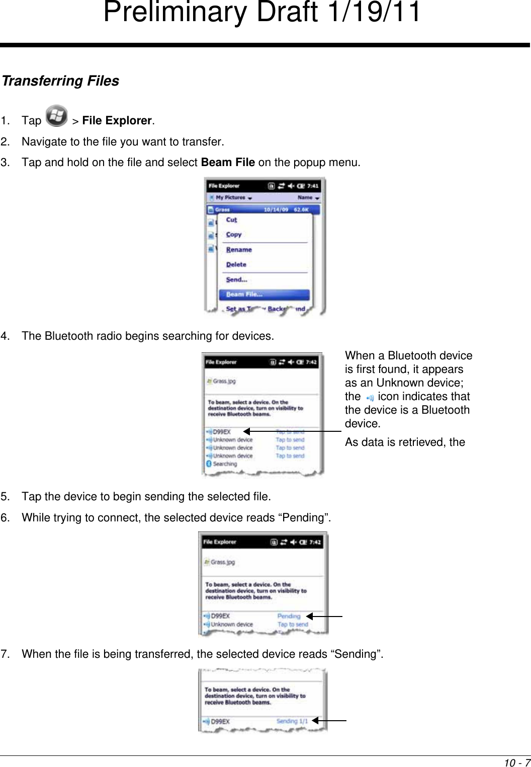
>
Honeywell
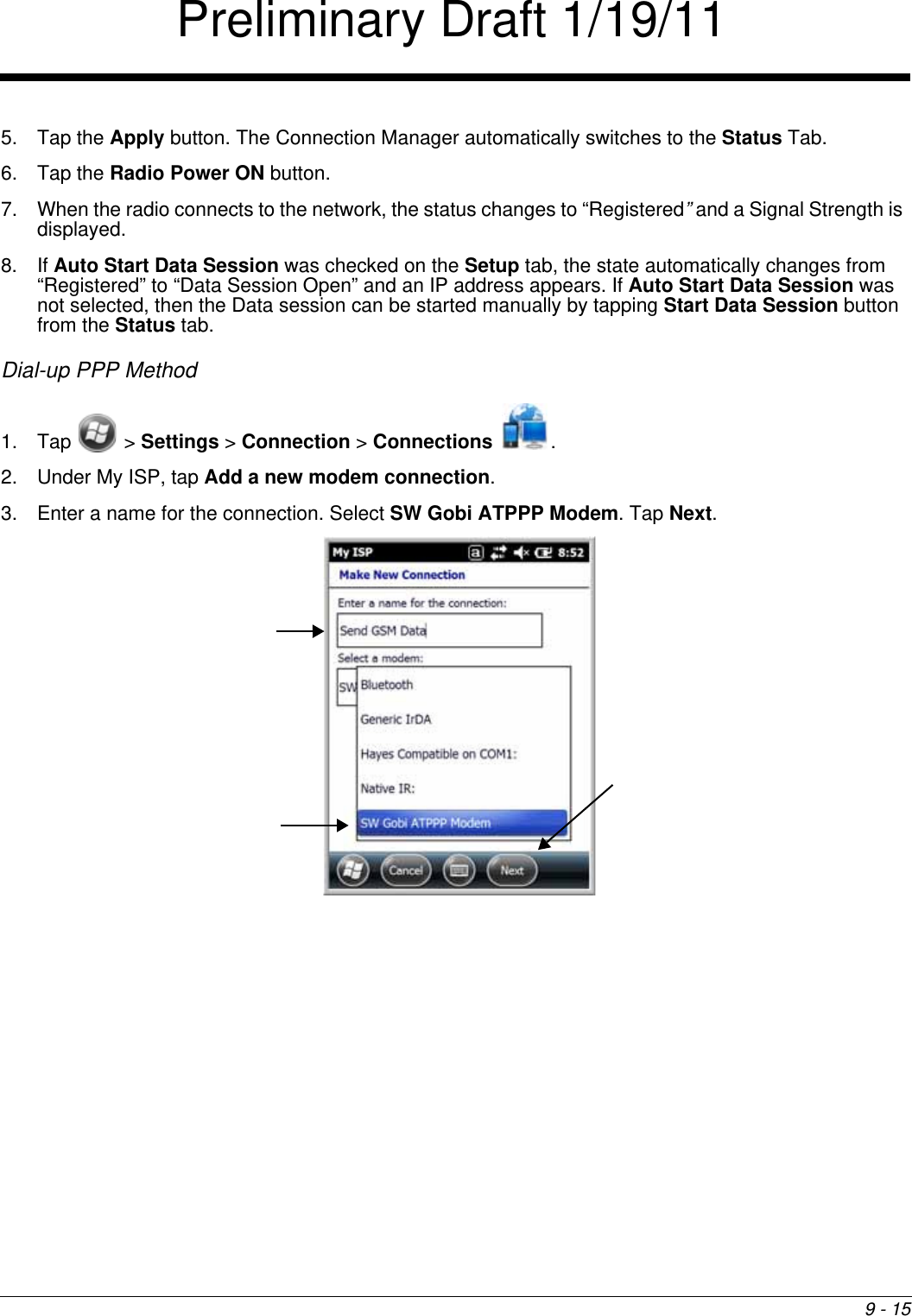
>
99EXLW User Manual
>
user manual 2 of 2
Contents
1.
User Manual 1 of 2
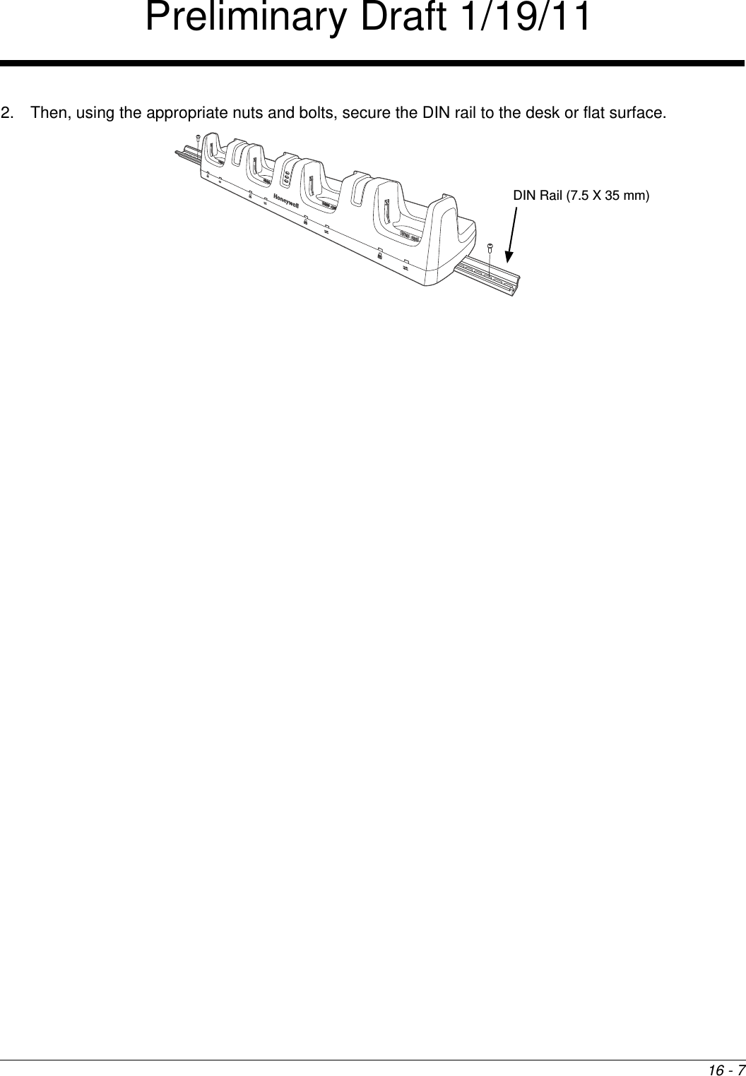
2.
user manual 2 of 2
3.
user manual 1 of 2
4.
User Manual
user manual 2 of 2
Navigation menu
Upload a User Manual
Namespaces
Wiki Guide
HTML
PDF
Info
Views
User Manual
Discussion / Help
Navigation