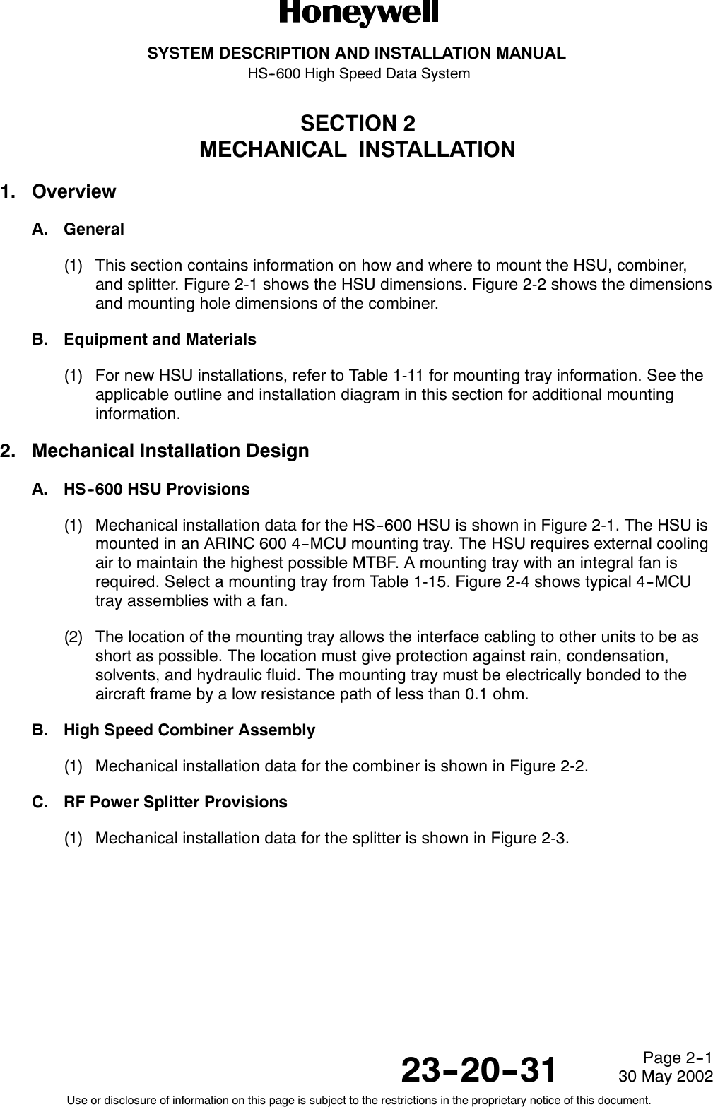
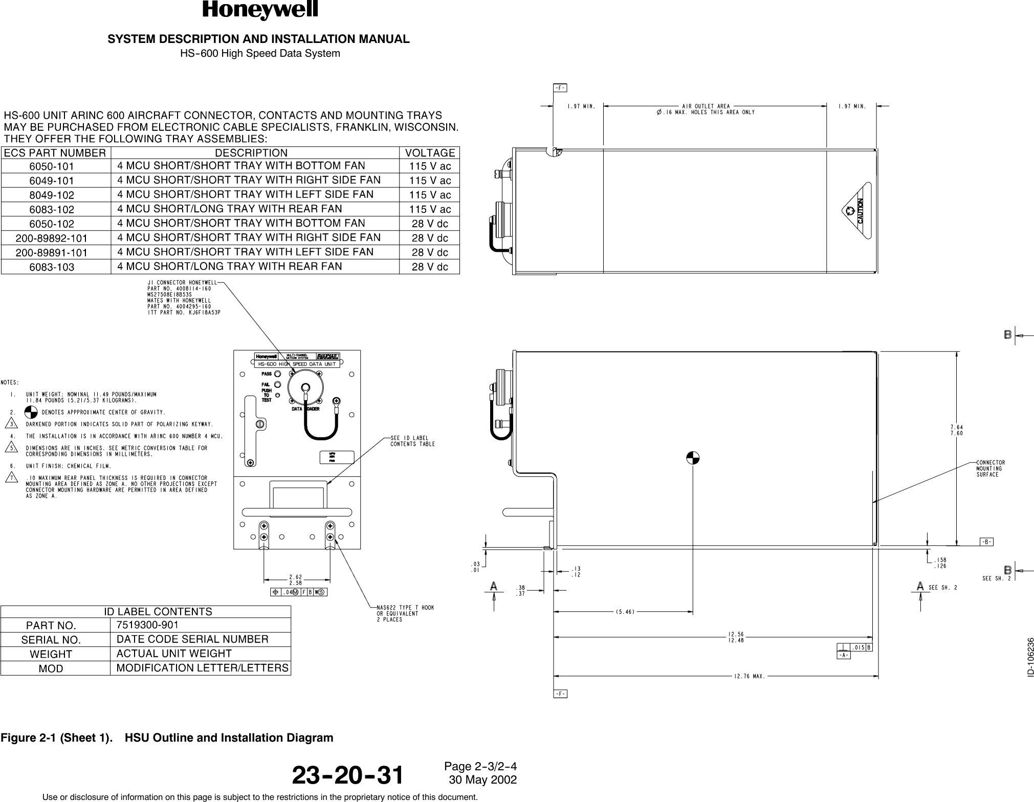
Honeywell HS-600 Inmarsat Aircraft Telecommunications Systems User Manual Manual
Honeywell International Inc. Inmarsat Aircraft Telecommunications Systems Manual
UserManual.wiki
>
Honeywell
>
HS 600 User Manual
Manual
Navigation menu
Upload a User Manual
Namespaces
Wiki Guide
HTML
PDF
Info
Views
User Manual
Discussion / Help
Navigation


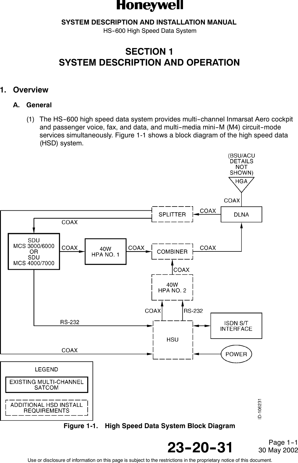
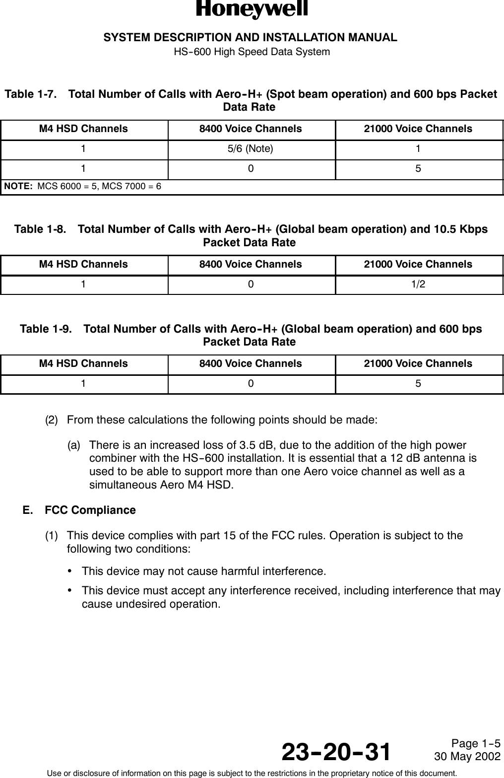
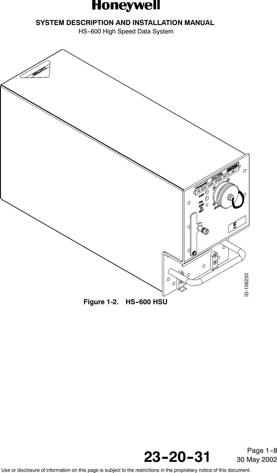
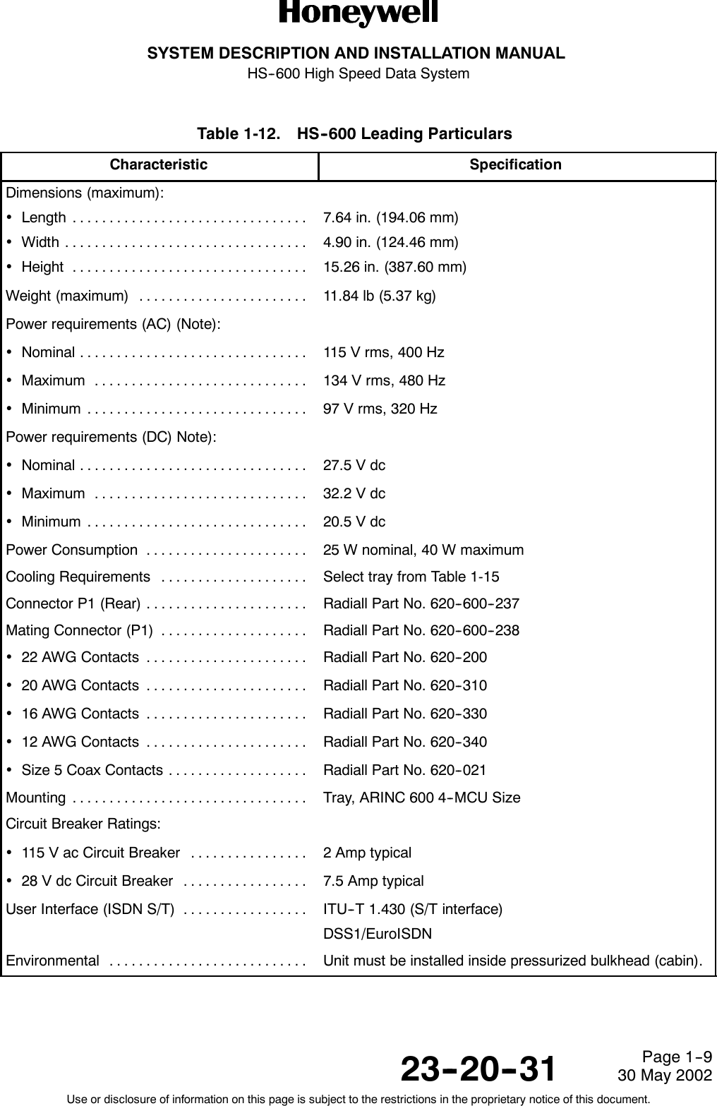


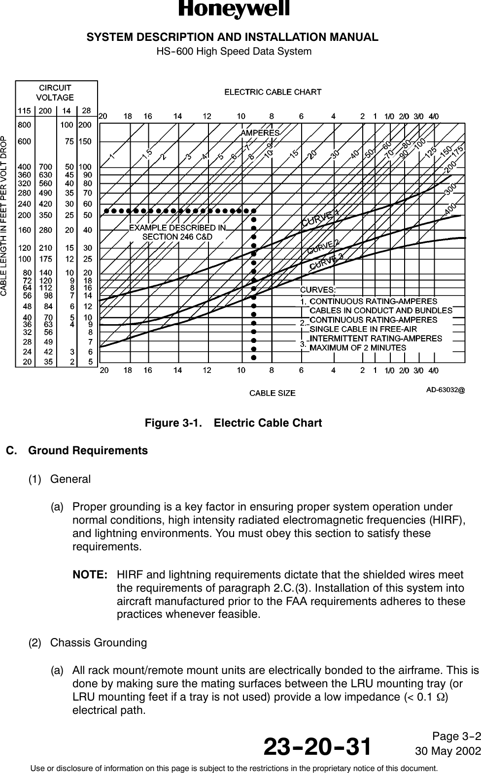
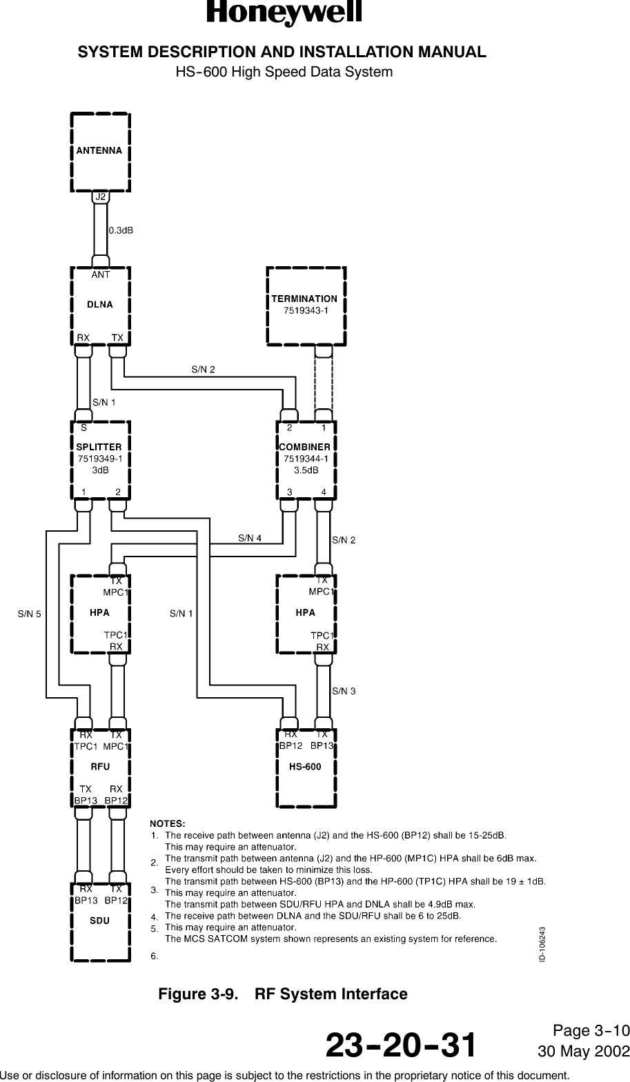
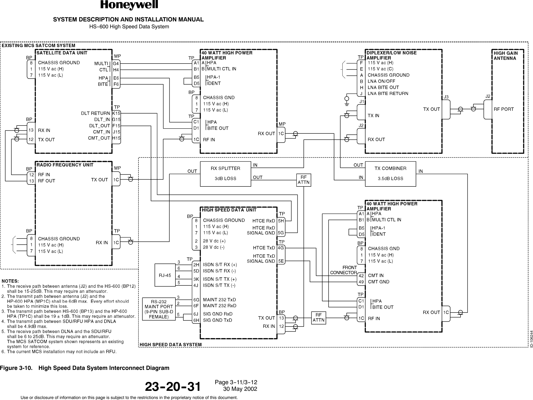
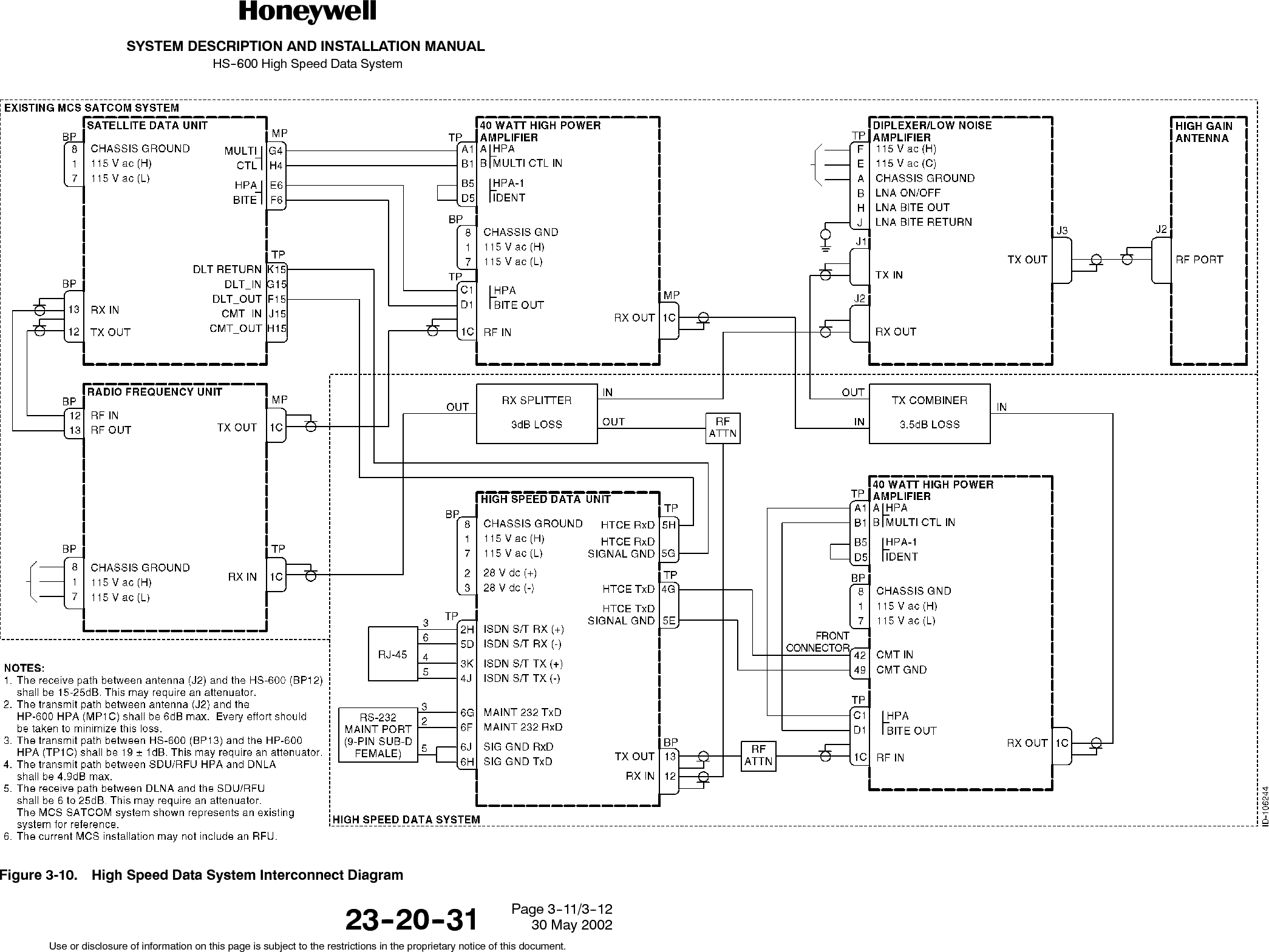
![SYSTEM DESCRIPTION AND INSTALLATION MANUALHS--600 High Speed Data System23--20--3130 May 2002Use or disclosure of information on this page is subject to the restrictions in the proprietary notice of this document.Page 3--1SECTION 3ELECTRICAL INSTALLATION1. OverviewA. General(1) This section gives electrical installation procedures, power distribution, andinterconnect information for the HSU, combiner, and splitter.(2) Procedures for proper shield, power, and signal grounding are also provided in thissection. In addition, procedures for the various buses are included.B. Equipment and Materials(1) See leading particulars table for a list of mating connectors required to do theelectrical installation.2. Electrical Installation ProcedureA. General(1) The information necessary to provide the electrical interconnects is contained in thefollowing paragraphs.B. Power Requirements(1) AC Power -- The aircraft ac power inverters must supply single phase 115 V ac(min 97, max 134 V ac) 400±80 Hz sine wave with a maximum total harmonicdistortion of 5%. Under all load conditions, amplitude modulation of the power supplywill not exceed 2% at any frequency. (Percent modulation is defined as one--half ofthe peak--to--peak modulation envelope divided by the carrier amplitude andmultiplied by 100.)(2) DC Power -- The aircraft dc power supply must be 28 V dc (nominal). The normalminimum and maximum voltages permitted are 20.5 and 32.2 V dc respectively.(3) Power supply to the HSU -- The voltage level of the power supplied to the HSU isimportant in this installation. The potential is the difference between the power pinsand power ground pins at the line replaceable unit (LRU). Excessive voltage drops inthe power wire(s) and power ground wire(s) cause one or more of the followingconditions:•The LRU draws additional current from the aircraft supply system.•Since the LRU is drawing more current, it produces more heat and more heatcauses a lower LRU MTBF.(4) The recommended maximum total combined voltage drop (voltage drop of the powerwire[s] plus voltage drop of the power ground wire[s]) is 1.0 V. Voltage drop is afunction of current and resistance (resistance in this case is a function of wire gaugeand wire length). See Figure 3-1 for determining proper wire gauge for LRU powerand power ground wires.](https://usermanual.wiki/Honeywell/HS-600/User-Guide-245053-Page-53.png)


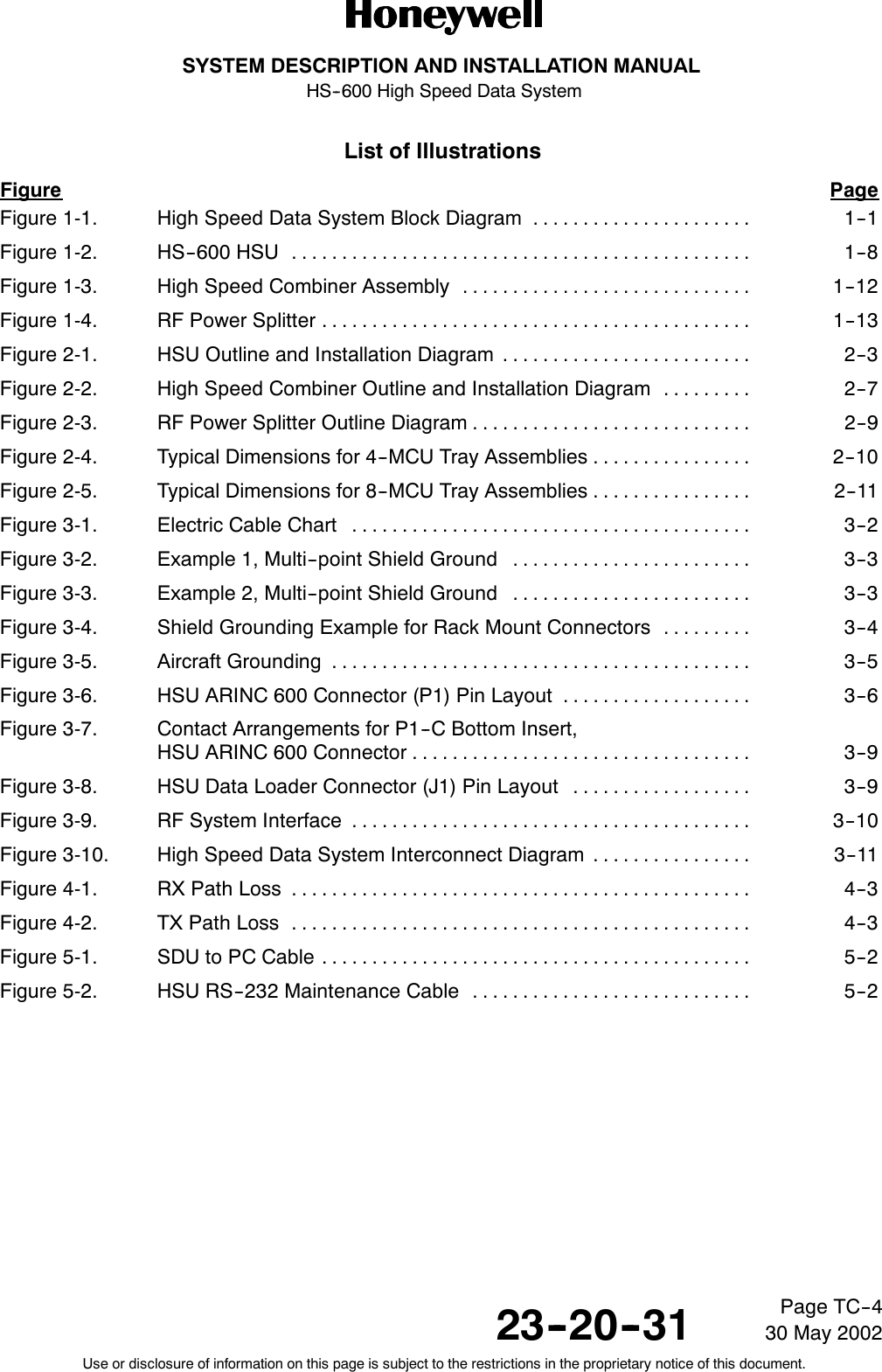
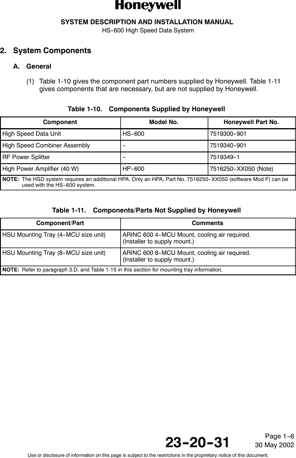
![SYSTEM DESCRIPTION AND INSTALLATION MANUALHS--600 High Speed Data System23--20--3130 May 2002Use or disclosure of information on this page is subject to the restrictions in the proprietary notice of this document.Page 5--4Table 5-3. Typical HS--600 Maintenance Port Information (cont)Glocom Multi Channel M4 Terminal IDU software start up...IDU SW Version: A1.00 04/05/2002Initializing channel 0...copy bulletin board from flash memory ok, issue no is 23Initializing channel 1...copy bulletin board from flash memory ok, issue no is 23!!!!!!!!!!!!!!!!!!!!!!!!!!!!!!!!!!!!!!!!!!!!!!!!!!!Waiting for LOG ON message from HTCE!!!!!!!!!!!!!!!!!!!!!!!!!!!!!!!!!!!!!!!!!!!!!!!!!!!!!!Power Control: PH(0) = 15.0EIRP(0) = 25.0PM(0) = 9.5GH(0) = 58.0Obo(0) = 2.0Set Economy Flag = 0IIIIIIIIIIIIIIIIIIIIIIIIIIIIIIIIIIIIIIIIIIIIIIIIIIIIIIIIIIIIIIIIIIIIIIIIIIIIIIIIIIIIII¯§§§ Press [ENTER] to start Maintenance Setting §§§EIIIIIIIIIIIIIIIIIIIIIIIIIIIIIIIIIIIIIIIIIIIIIIIIIIIIIIIIIIIIIIIIIIIIIIIIIIIIIIIIIIIII00.900:APP--SM |SM_CONFIG_CO |ff:ff:ff#0:Config APP OK( 20), ISDN module buffer allocated= 1( 40), ISDN module buffer allocated= 1* Have found “Format B”( 60), ISDN module buffer allocated= 1( 80), ISDN module buffer allocated= 1( 100), ISDN module buffer allocated= 1* Have found “Format B”( 120), ISDN module buffer allocated= 1( 140), ISDN module buffer allocated= 1](https://usermanual.wiki/Honeywell/HS-600/User-Guide-245053-Page-73.png)