Honeywell HS-600 Inmarsat Aircraft Telecommunications Systems User Manual Manual
Honeywell International Inc. Inmarsat Aircraft Telecommunications Systems Manual
Manual

This document contains technical data and is subject to U.S. export regulations.
These commodities, technology, or software were exported from the United States in accordance with the
export administration regulations. Diversion contrary to U.S. law is prohibited.
Honeywell
Aerospace Electronic Systems
CES--Phoenix
P.O. Box 21111
Phoenix, Arizona 85036-1111
U.S.A.
Printed in U.S.A. Pub. No. A15--5111--006
23--20--31
Title Page T--1
30 May 2002
System Description and Installation
Manual
HS--600
High Speed Data System

SYSTEM DESCRIPTION AND INSTALLATION MANUAL
HS--600 High Speed Data System
PROPRIETARY NOTICE
This document and the information disclosed herein are proprietary data of Honeywell. Neither
this document nor the information contained herein shall be used, reproduced, or disclosed to
others without the written authorization of Honeywell, except to the extent required for
installation or maintenance of the recipient’s equipment.
NOTICE -- FREEDOM OF INFORMATION ACT (5 USC 552) AND
DISCLOSURE OF CONFIDENTIAL INFORMATION GENERALLY (18 USC 1905)
This document is being furnished in confidence by Honeywell. The information disclosed
herein fall within exemption (b) (4) of 5 USC 552 and the prohibitions of 18 USC 1905.
S2002
Honeywell is a U.S. registered trademark of Honeywell. All other marks are owned by their respective companies.
Copyright 2002 Honeywell
All Rights Reserved
23--20--31
Title Page T--2
30 May 2002
Please cut along the dotted line.Please cut along the dotted line.
REPORT OF POSSIBLE DATA ERROR
FOR HONEYWELL USE ONLY
CONTROL NO.
DATE RECEIVED
Please mail or FAX completed form to Technical Publications Quality Administrator. If returning by mail, please tape this form closed (U.S. postal
regulations prohibit the use of staples). If sending by FAX, the Technical Publications’ U.S. FAX No. is (602- 436- 3900). If sending by email, the email address
is tpqa@honeywell.com.
Local reproduction of this form is encouraged. This form is based on electronic form INF--300, Revision 0
To help us improve the quality of our publication, Honeywell encourages any report of a possible data error.
PUBLICATION INFORMATION
Publication
Number
A15-- 5111--006
Volume No.
(Book, or
Addendum)
ATA
Number
23--20--31
Latest Issue Date
From Title Page
Publication
Title
High Speed Data Unit
Document
Type
System Description and Installation
Manual
READER INFORMATION
Please check all that apply:
hTrainer hTechnician hLibrarian hEngineer hOther
(Please specify)
Your Name (optional) Company Name
Street Address City, State (Province),
Zip Code, Country
Telephone No. FAX No.
POSSIBLE DATA ERROR
Page
No.
Paragraph
Figure No. Table No. Description of Possible Data Error
HONEYWELL REPLY
DO NOT STAPLE
DO NOT STAPLE
BUSINESS REPLY MAIL
FIRST CLASS PERMIT NO. 3532, PHOENIX, AZ
FOLD
FOLD
POSTAGE WILL BE PAID BY ADDRESSEE
Honeywell
Aerospace Electronic Systems
CES--Phoenix
P.O. Box 21111
Phoenix, Arizona 85036-1111
U.S.A.
ATTN: Technical Publications
Quality Administrator
NO POSTAGE
NECESSARY
IF MAILED
IN THE
UNITED STATES
Please cut along the dotted line.Please cut along the dotted line.
CUSTOMER RESPONSE
FOR HONEYWELL USE ONLY
CONTROL NO.
DATE RECEIVED
Please mail or FAX completed form to Technical Publications Quality Administrator. If returning by mail, please tape closed (U.S. postal regulations prohibit
the use of staples). If sending by FAX, the Technical Publications’ U.S. FAX No. is (602- 436- 3900). If sending by email, the email address is
tpqa@honeywell.com.
Local reproduction of this form is encouraged.
To help us improve the quality of our publications, Honeywell encourages readers to provide input to the
customer--satisfaction survey below. We welcome all comments and recommendations.
PUBLICATION INFORMATION
Publication
Number
A15-- 5111--006
Volume No.
(Book, or
Addendum)
ATA
Number
23--20--31
Latest Issue Date
From Title Page
Publication
Title
High Speed Data Unit
Document
Type
System Description and Installation Manual
READER INFORMATION
Please check all that apply:
hTrainer hTechnician hLibrarian hEngineer hOther
(Please specify)
Your Name (optional) Company Name
S
t
r
e
e
t
A
d
d
r
e
s
s
C
i
t
y
,S
t
a
t
e
(
P
ro
v
i
nce
)
,
S
t
ree
t
A
d
d
ress
C
i
t
y
,
S
t
a
t
e
(
P
r
o
v
i
n
c
e
)
,
Zip Code, Country
Telephone No. FAX No.
CUSTOMER--SATISFACTION SURVEY
Please check the yes or no box to answer the following questions: Yes No
1. Is the Publication technically accurate?
j j
2. Is information easy to find?
j j
3. Is information complete?
j j
4. Are figures easy to use?
j j
5. Are tables easy to use
j j
6. Is the Publication used for training?
j j
7. Do you or your organization wish to remain on distribution for this publication?
j j
Please rate this publication in comparison to other documents you use. Good Fair Poor
jjj
Please provide comments, recommendations and/or improvements that you would like to see in this publication.
DO NOT STAPLE
DO NOT STAPLE
BUSINESS REPLY MAIL
FIRST CLASS PERMIT NO. 3532, PHOENIX, AZ
FOLD
FOLD
POSTAGE WILL BE PAID BY ADDRESSEE
Honeywell
Aerospace Electronic Systems
CES--Phoenix
P.O. Box 21111
Phoenix, Arizona 85036-1111
U.S.A.
ATTN: Technical Publications
Quality Administrator
NO POSTAGE
NECESSARY
IF MAILED
IN THE
UNITED STATES

SYSTEM DESCRIPTION AND INSTALLATION MANUAL
HS--600 High Speed Data System
23--20--31
30 May 2002
Use or disclosure of information on this page is subject to the restrictions in the proprietary notice of this document.
Page RR--1
RECORD OF REVISIONS
For each revision, put the revised pages in your manual and discard the superseded pages. Write
the revision number and date, date put in manual, and the incorporator’s initials in the applicable
columns on the Record of Revisions. The initial H shows Honeywell is the incorporator.
Revision
Number
Revision
Date
Date Put
In Manual By
Revision
Number
Revision
Date
Date Put
In Manual By

SYSTEM DESCRIPTION AND INSTALLATION MANUAL
HS--600 High Speed Data System
23--20--31
30 May 2002
Use or disclosure of information on this page is subject to the restrictions in the proprietary notice of this document.
Page RR--2
Blank Page

SYSTEM DESCRIPTION AND INSTALLATION MANUAL
HS--600 High Speed Data System
23--20--31
30 May 2002
Use or disclosure of information on this page is subject to the restrictions in the proprietary notice of this document.
Page RTR--1
RECORD OF TEMPORARY REVISIONS
Instructions on each page of a temporary revision tell you where to put the pages in your manual.
Remove temporary revision pages only when discard instructions are given. For each temporary
revision, put the applicable data in the record columns on this page.
Temporary
Revision
Number
Temporary
Revision
Date
Temporary
Revision
Status
Date Put
in Manual By *
Date
Removed
from Manual By *
* The initial H in this column shows Honeywell has done this task.

SYSTEM DESCRIPTION AND INSTALLATION MANUAL
HS--600 High Speed Data System
23--20--31
30 May 2002
Use or disclosure of information on this page is subject to the restrictions in the proprietary notice of this document.
Page RTR--2
Blank Page

SYSTEM DESCRIPTION AND INSTALLATION MANUAL
HS--600 High Speed Data System
23--20--31
30 May 2002
Use or disclosure of information on this page is subject to the restrictions in the proprietary notice of this document.
Page SBL--1
SERVICE BULLETIN LIST
Service Bulletin
Identified
Mod
Date Included
in this Manual Description

SYSTEM DESCRIPTION AND INSTALLATION MANUAL
HS--600 High Speed Data System
23--20--31
30 May 2002
Use or disclosure of information on this page is subject to the restrictions in the proprietary notice of this document.
Page SBL--2
Blank Page

SYSTEM DESCRIPTION AND INSTALLATION MANUAL
HS--600 High Speed Data System
23--20--31
30 May 2002
Use or disclosure of information on this page is subject to the restrictions in the proprietary notice of this document.
Page LEP--1
LIST OF EFFECTIVE PAGES
Subheading and Page Date Subheading and Page Date
Title
T--1 30 May 2002
T--2 30 May 2002
Record of Revisions
RR--1 30 May 2002
RR--2 30 May 2002
Record of Temporary Revisions
RTR--1 30 May 2002
RTR--2 30 May 2002
Service Bulletin List
SBL--1 30 May 2002
SBL--2 30 May 2002
List of Effective Pages
LEP--1 30 May 2002
LEP--2 30 May 2002
Table of Contents
TC--1 30 May 2002
TC--2 30 May 2002
TC--3 30 May 2002
TC--4 30 May 2002
TC--5 30 May 2002
TC--6 30 May 2002
Introduction
INTRO--1 30 May 2002
INTRO--2 30 May 2002
INTRO--3 30 May 2002
INTRO--4 30 May 2002
System Description and Operation
1--1 30 May 2002
1--2 30 May 2002
1--3 30 May 2002
1--4 30 May 2002
1--5 30 May 2002
1--6 30 May 2002
1--7 30 May 2002
1--8 30 May 2002
1--9 30 May 2002
1--10 30 May 2002
1--11 30 May 2002
1--12 30 May 2002
1--13 30 May 2002
1--14 30 May 2002
Mechanical Installation
2--1 30 May 2002
2--2 30 May 2002
F
2--3/2--4 30 May 2002
F
2--5/2--6 30 May 2002
F
2--7/2--8 30 May 2002
2--9 30 May 2002
2--10 30 May 2002
2--11 30 May 2002
2--12 30 May 2002
Electrical Installation
3--1 30 May 2002
3--2 30 May 2002
3--3 30 May 2002
3--4 30 May 2002
3--5 30 May 2002
3--6 30 May 2002
3--7 30 May 2002
3--8 30 May 2002
3--9 30 May 2002
3--10 30 May 2002
F
3--11/3--12 30 May 2002
Hindicates a changed or added page.
F indicates a foldout page.

SYSTEM DESCRIPTION AND INSTALLATION MANUAL
HS--600 High Speed Data System
23--20--31
30 May 2002
Use or disclosure of information on this page is subject to the restrictions in the proprietary notice of this document.
Page LEP--2
Subheading and Page Date Subheading and Page Date
Installation Check
4--1 30 May 2002
4--2 30 May 2002
4--3 30 May 2002
4--4 30 May 2002
Adjustment/test
5--1 30 May 2002
5--2 30 May 2002
5--3 30 May 2002
5--4 30 May 2002
5--5 30 May 2002
5--6 30 May 2002
5--7 30 May 2002
5--8 30 May 2002
Fault Isolation
6--1 30 May 2002
6--2 30 May 2002
Maintenance Practices
7--1 30 May 2002
7--2 30 May 2002
7--3 30 May 2002
7--4 30 May 2002
M4 Call Cause Code List
A--1 30 May 2002
A--2 30 May 2002
A--3 30 May 2002
A--4 30 May 2002
A--5 30 May 2002
A--6 30 May 2002
A--7 30 May 2002
A--8 30 May 2002
A--9 30 May 2002
A--10 30 May 2002
Inmarsat Registration Form
B--1 30 May 2002
B--2 30 May 2002
B--3 30 May 2002
B--4 30 May 2002
B--5 30 May 2002
B--6 30 May 2002
B--7 30 May 2002
B--8 30 May 2002
B--9 30 May 2002
B--10 30 May 2002
Hindicates a changed or added page.
F indicates a foldout page.

CONTENTS

SYSTEM DESCRIPTION AND INSTALLATION MANUAL
HS--600 High Speed Data System
23--20--31
30 May 2002
Use or disclosure of information on this page is subject to the restrictions in the proprietary notice of this document.
Page TC--1
TABLE OF CONTENTS
Subject Page
INTRODUCTION INTRO--1...........................................................
1. Proprietary, Export, and Precautionary Data INTRO--1...............................
A. Proprietary Notice INTRO--1..................................................
B. Export Notice INTRO--1......................................................
C. Special Precautions INTRO--1................................................
2. Content Data INTRO--2..........................................................
A. How to Use This Manual INTRO--2............................................
B. Weights and Measurements INTRO--3.........................................
C. Acronyms and Abbreviations INTRO--3.........................................
3. Customer Assistance INTRO--4...................................................
A. Who to Contact INTRO--4....................................................
SYSTEM DESCRIPTION AND OPERATION 1--1..................................
1. Overview 1--1..............................................................
A. General 1--1...........................................................
B. Aero--H/H+ 1--3........................................................
C. Inmarsat High Speed Systems 1--3.......................................
D. System Performance 1--4...............................................
E. FCC Compliance 1--5...................................................
2. System Components 1--6...................................................
A. General 1--6...........................................................
3. Component Descriptions 1--7................................................
A. HS--600 High Speed Data Unit (HSU) 1--7.................................
B. High Speed Combiner Assembly 1--12.....................................
C. RF Power Splitter 1--13..................................................
D. HSU Mounting Tray 1--13.................................................
MECHANICAL INSTALLATION 2--1.............................................
1. Overview 2--1..............................................................
A. General 2--1...........................................................
B. Equipment and Materials 2--1............................................
2. Mechanical Installation Design 2--1...........................................
A. HS--600 HSU Provisions 2--1............................................

SYSTEM DESCRIPTION AND INSTALLATION MANUAL
HS--600 High Speed Data System
23--20--31
30 May 2002
Use or disclosure of information on this page is subject to the restrictions in the proprietary notice of this document.
Page TC--2
B. High Speed Combiner Assembly 2--1.....................................
C. RF Power Splitter Provisions 2--1.........................................
ELECTRICAL INSTALLATION 3--1..............................................
1. Overview 3--1..............................................................
A. General 3--1...........................................................
B. Equipment and Materials 3--1............................................
2. Electrical Installation Procedure 3--1..........................................
A. General 3--1...........................................................
B. Power Requirements 3--1...............................................
C. Ground Requirements 3--2..............................................
(1) General 3--2.......................................................
(2) Chassis Grounding 3--2.............................................
(3) Shield Grounds 3--3................................................
(4) Power/Signal Grounds 3--4..........................................
3. Electrical Installation 3--5....................................................
A. HS--600 HSU 3--5......................................................
INSTALLATION CHECK 4--1....................................................
1. Overview 4--1..............................................................
A. General 4--1...........................................................
2. Installation Checkout 4--1...................................................
A. General 4--1...........................................................
B. Cable Loss Checks 4--1.................................................
(1) HS--600 HSU to HPA Path Loss 4--1..................................
(2) HPA to Antenna Loss 4--1...........................................
C. Power Checks 4--2.....................................................
D. RF Checks 4--2........................................................
ADJUSTMENT/TEST 5--1.......................................................
1. Overview 5--1..............................................................
A. General 5--1...........................................................
2. Details 5--1................................................................
A. General 5--1...........................................................
B. Software 5--1..........................................................
C. System Initialization 5--1................................................

SYSTEM DESCRIPTION AND INSTALLATION MANUAL
HS--600 High Speed Data System
23--20--31
30 May 2002
Use or disclosure of information on this page is subject to the restrictions in the proprietary notice of this document.
Page TC--3
D. Typical Maintenance Port Start--Up Information 5--3........................
E. Maintenance Menu Items 5--6............................................
FAULT ISOLATION 6--1........................................................
1. Overview 6--1..............................................................
A. General 6--1...........................................................
MAINTENANCE PRACTICES 7--1...............................................
1. Overview 7--1..............................................................
A. General 7--1...........................................................
B. Equipment and Materials 7--1............................................
2. Procedure for the HS--600 HSU 7--1..........................................
A. Removal and Reinstallation Procedures 7--1...............................
B. Adjustment Procedures 7--2.............................................
C. Repair Procedures 7--2.................................................
D. Return to Service Procedures 7--2........................................
3. Procedure for the Combiner/Splitter 7--2......................................
A. Removal and Reinstallation Procedures 7--2...............................
B. Adjustment Procedures 7--3.............................................
C. Repair Procedures 7--3.................................................
D. Return to Service Procedures 7--3........................................
4. Instructions for Continued Airworthiness, Code of Federal Regulation
CFR 91.213 7--4...........................................................
A. General 7--4...........................................................
B. Instructions 7--4........................................................
APPENDIX A
M4 CALL CAUSE CODE LIST A--1...............................................
1. Overview A--1..............................................................
A. General A--1...........................................................
APPENDIX B
INMARSAT REGISTRATION FORM B--1..........................................
1. Overview B--1..............................................................
A. General B--1...........................................................

SYSTEM DESCRIPTION AND INSTALLATION MANUAL
HS--600 High Speed Data System
23--20--31
30 May 2002
Use or disclosure of information on this page is subject to the restrictions in the proprietary notice of this document.
Page TC--4
List of Illustrations
Figure Page
Figure 1-1. High Speed Data System Block Diagram 1--1......................
Figure 1-2. HS--600 HSU 1--8..............................................
Figure 1-3. High Speed Combiner Assembly 1--12.............................
Figure 1-4. RF Power Splitter 1--13...........................................
Figure 2-1. HSU Outline and Installation Diagram 2--3.........................
Figure 2-2. High Speed Combiner Outline and Installation Diagram 2--7.........
Figure 2-3. RF Power Splitter Outline Diagram 2--9............................
Figure 2-4. Typical Dimensions for 4--MCU Tray Assemblies 2--10................
Figure 2-5. Typical Dimensions for 8--MCU Tray Assemblies 2--11................
Figure 3-1. Electric Cable Chart 3--2........................................
Figure 3-2. Example 1, Multi--point Shield Ground 3--3........................
Figure 3-3. Example 2, Multi--point Shield Ground 3--3........................
Figure 3-4. Shield Grounding Example for Rack Mount Connectors 3--4.........
Figure 3-5. Aircraft Grounding 3--5..........................................
Figure 3-6. HSU ARINC 600 Connector (P1) Pin Layout 3--6...................
Figure 3-7. Contact Arrangements for P1--C Bottom Insert,
HSU ARINC 600 Connector 3--9..................................
Figure 3-8. HSU Data Loader Connector (J1) Pin Layout 3--9..................
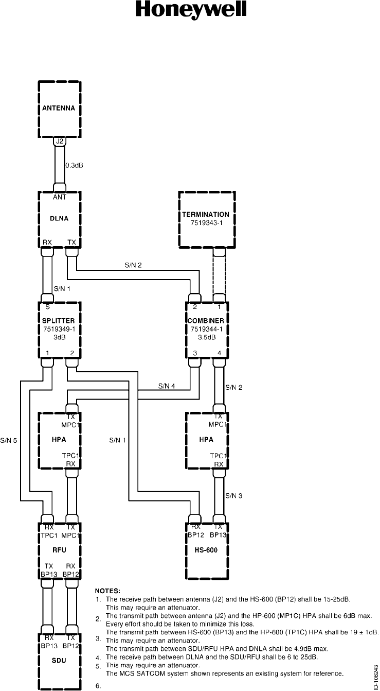
Figure 3-9. RF System Interface 3--10........................................
Figure 3-10. High Speed Data System Interconnect Diagram 3--11................
Figure 4-1. RX Path Loss 4--3..............................................
Figure 4-2. TX Path Loss 4--3..............................................
Figure 5-1. SDU to PC Cable 5--2...........................................
Figure 5-2. HSU RS--232 Maintenance Cable 5--2............................

SYSTEM DESCRIPTION AND INSTALLATION MANUAL
HS--600 High Speed Data System
23--20--31
30 May 2002
Use or disclosure of information on this page is subject to the restrictions in the proprietary notice of this document.
Page TC--5
List of Tables
Table Intro--1. Related Publications INTRO--2.......................................
Table 1-1. SDU DLT RS--232 Port Configuration 1--2.........................
Table 1-2. SDU CMT Keystrokes 1--2......................................
Table 1-3. Type of Service 1--3............................................
Table 1-4. Assumptions 1--4..............................................
Table 1-5. Calculations 1--4...............................................
Table 1-6. Total Number of Calls with Aero--H+ (Spot beam operation)
and 10.5 Kbps Packet Data Rate 1--4............................
Table 1-7. Total Number of Calls with Aero--H+ (Spot beam operation)
and 600 bps Packet Data Rate 1--5..............................
Table 1-8. Total Number of Calls with Aero--H+ (Global beam operation)
and 10.5 Kbps Packet Data Rate 1--5............................
Table 1-9. Total Number of Calls with Aero--H+ (Global beam operation)
and 600 bps Packet Data Rate 1--5..............................
Table 1-10. Components Supplied by Honeywell 1--6.........................
Table 1-11. Components/Parts Not Supplied by Honeywell 1--6................
Table 1-12. HS--600 Leading Particulars 1--9.................................
Table 1-13. DO--160D Environmental Categories 1--10.........................
Table 1-14. HSU Front Panel Light Description 1--11...........................
Table 1-15. HSU Mounting Trays 1--14.......................................
Table 3-1. Contact Arrangements for P1--A Top Insert,
HSU ARINC 600 Connector 3--7.................................
Table 3-2. Contact Arrangements for P1--B Top Insert,
HSU ARINC 600 Connector 3--8.................................
Table 4-1. Power Checks 4--2.............................................
Table 4-2. RF Checks 4--2................................................
Table 5-1. SDU to PC Wire List 5--1........................................
Table 5-2. HSU to RS--232 Maintenance Port Wire List 5--2...................
Table 5-3. Typical HS--600 Maintenance Port Information 5--3.................
Table 5-4. Maintenance Menu Items 5--6...................................
Table A--1. Call Cause Code List A--1.......................................

SYSTEM DESCRIPTION AND INSTALLATION MANUAL
HS--600 High Speed Data System
23--20--31
30 May 2002
Use or disclosure of information on this page is subject to the restrictions in the proprietary notice of this document.
Page TC--6
Blank Page

INTRODUCTION

SYSTEM DESCRIPTION AND INSTALLATION MANUAL
HS--600 High Speed Data System
23--20--31
30 May 2002
Use or disclosure of information on this page is subject to the restrictions in the proprietary notice of this document.
Page INTRO--1
INTRODUCTION
1. Proprietary, Export, and Precautionary Data
A. Proprietary Notice
(1) This document and the information disclosed herein are proprietary data of
Honeywell. Neither this document nor the information contained herein shall be used,
reproduced, or disclosed to others without the written authorization of Honeywell,
except to the extent required for installation or maintenance of the recipient’s
equipment. FREEDOM OF INFORMATION ACT (5 USC 552) AND DISCLOSURE
OF CONFIDENTIAL INFORMATION GENERALLY (18 USC 1905).
(2) This document is being furnished in confidence by Honeywell. The information
disclosed herein falls within exemption (b) (4) of 5 USC 552 and the prohibitions of 18
USC 1905. Copyright 2002 Honeywell. All Rights Reserved.
(3) Honeywell is a U.S. registered trademark of Honeywell. All other marks are owned by
their respective companies.
B. Export Notice
(1) This document contains unrestricted technical data and is being exported under
license exception TSU/OTS in accordance with EAR Section 740.13(a).
(2) These commodities, technology, or software were exported from the United States in
accordance with the export administration regulations. Diversion contrary to U.S. law
is prohibited. ECCN: 7E994 Schedule B#4901.99.0050
C. Special Precautions
(1) Warnings, cautions, and notes in this manual give the data that follows:
•A WARNING is an operation or maintenance procedure or condition that, if not
obeyed, can cause injury or death.
•A CAUTION is an operation or maintenance procedure or condition that, if not
obeyed, can cause damage to the equipment.
•A NOTE gives data to make the work easier or gives directions to go to a
procedure.
(2) All personnel who operate equipment and do maintenance specified in this manual
must know and obey the safety precautions. The warnings and cautions that follow
apply to all parts of this manual.

SYSTEM DESCRIPTION AND INSTALLATION MANUAL
HS--600 High Speed Data System
23--20--31
30 May 2002
Use or disclosure of information on this page is subject to the restrictions in the proprietary notice of this document.
Page INTRO--2
WARNING: BEFORE YOU USE A MATERIAL, REFER TO THE MANUFACTURERS’
MATERIAL SAFETY DATA SHEETS FOR SAFETY INFORMATION. SOME
MATERIALS CAN BE DANGEROUS.
CAUTION: DO NOT USE MATERIALS THAT ARE NOT EQUIVALENT TO
MATERIALS SPECIFIED BY HONEYWELL. MATERIALS THAT ARE NOT
EQUIVALENT CAN CAUSE DAMAGE TO THE EQUIPMENT AND CAN
VOID THE WARRANTY.
CAUTION: THE HS--600 HIGH SPEED DATA SYSTEM CONTAINS ITEMS THAT ARE
ELECTROSTATIC DISCHARGE SENSITIVE (ESDS). IF YOU DO NOT
OBEY THE NECESSARY CONTROLS, A FAILURE OR
UNSATISFACTORY OPERATION OF THE UNIT CAN OCCUR FROM
ELECTROSTATIC DISCHARGE. USE APPROVED INDUSTRY
PRECAUTIONS TO KEEP THE RISK OF DAMAGE TO A MINIMUM WHEN
YOU TOUCH, REMOVE, OR INSERT PARTS OR ASSEMBLIES.
2. Content Data
A. How to Use This Manual
(1) This manual gives general system description and installation information for the
HS--600 High Speed Data System. It also gives block diagram and interconnect
information to permit a general understanding of the system interface.
(2) The purpose of this manual is to help you install, operate, maintain, and troubleshoot
the HS--600 High Speed Data System. Common system maintenance procedures
are not presented in this manual. The best established shop and flight line practices
should be used.
(3) Related publications that are referred to in this manual are identified in Table Intro--1.
Table Intro--1. Related Publications
Publication Publication No.
Handling, Storage, and Shipping Procedures for Honeywell Avionics
Equipment Instruction Manual
A09--1100--001
MCS--3000/6000 Multi--Channel Satellite Communications System
Description, Installation, and Maintenance Manual
C15-- 5111 -- 005
MCS--4000/7000 Multi--Channel SATCOM System Description,
Installation, and Maintenance Manual
A15-- 5111 -- 001
NOTES:
1. You can order a Honeywell publication from Honeywell as follows:
Telephone No.: (602) 436--6900
Fax No.: (602) 436--1588
E--mail: cas--publications--distribution@honeywell.com

SYSTEM DESCRIPTION AND INSTALLATION MANUAL
HS--600 High Speed Data System
23--20--31
30 May 2002
Use or disclosure of information on this page is subject to the restrictions in the proprietary notice of this document.
Page INTRO--3
B. Weights and Measurements
(1) All weights and measurements are in U. S. values.
(2) The letter symbols for units of measurement are the same as shown in
ANSI/IEEE Std 260.
C. Acronyms and Abbreviations
(1) The acronyms and abbreviations that follow help the reader identify terms and
definitions used by Honeywell.
(2) The letter symbols for units of measurement are the same as shown in
ANSI/IEEE Std 260.
Term Definition
ACSE access control and signalling equipment
ACU antenna control unit
BSU beam steering unit
CCA circuit card assembly
CMT commissioning and maintenance terminal
CNS/ATM communication, navigation, and surveillance/air traffic management
DLNA diplexer/low noise amplifier
DLT data logging terminal
ESD electrostatic discharge
ESDS electrostatic discharge sensitive
HGA high gain antenna
HIRF high intensity radiated electromagnetic frequencies
HPA high power amplifier
HSD high speed data
HSU high speed data unit
ICAO International Civil Aviation Organization: Agency of the UN
IPC Illustrated Parts Catalog
IPDS Inmarsat Packet Mode Data Service
IRS inertial reference system
ISDN Integrated Services Digital Network
LES land earth station
LESA land earth station assignment
LRU line replaceable unit

SYSTEM DESCRIPTION AND INSTALLATION MANUAL
HS--600 High Speed Data System
23--20--31
30 May 2002
Use or disclosure of information on this page is subject to the restrictions in the proprietary notice of this document.
Page INTRO--4
Term Definition
M4 multi--media mini--M
MCS multi--channel SATCOM
MCU modular concept unit
MEL minimum equipment list
MES Mobile Earth Station
MM/HSD Mini M/high speed data
MTBF mean--time--between--failures
NCSA network coordination station assignment
PC personal computer
PID personal identification number
PSTN Public Switched Telephone Network
RF radio frequency
RFU radio frequency unit
SATCOM satellite communications
SCPC single channel per circuit
SDM System Definition Manual
SDU satellite data unit
SU signal unit
TDM time division multiplex
TDMA time division multiple access
3. Customer Assistance
A. WhotoContact
(1) For assistance with installation, operation, or maintenance of the HS--600 High
Speed Data System, contact your local Honeywell Dealer or regional Honeywell
Customer Support Engineer. Additional assistance can be obtained from:
•Honeywell
Aviation Services, Customer Response Center (CRC)
Commercial Electronic Systems
21111 N. 19th Avenue
Phoenix, AZ 85027
TEL: (877) 436--2005 (Toll--Free)
FAX: (602) 436--1501

SYSTEMS DESCRIPTION
AND OPERATION
SYSTEM DESCRIPTION AND INSTALLATION MANUAL
HS--600 High Speed Data System
23--20--31
30 May 2002
Use or disclosure of information on this page is subject to the restrictions in the proprietary notice of this document.
Page 1--1
SECTION 1
SYSTEM DESCRIPTION AND OPERATION
1. Overview
A. General
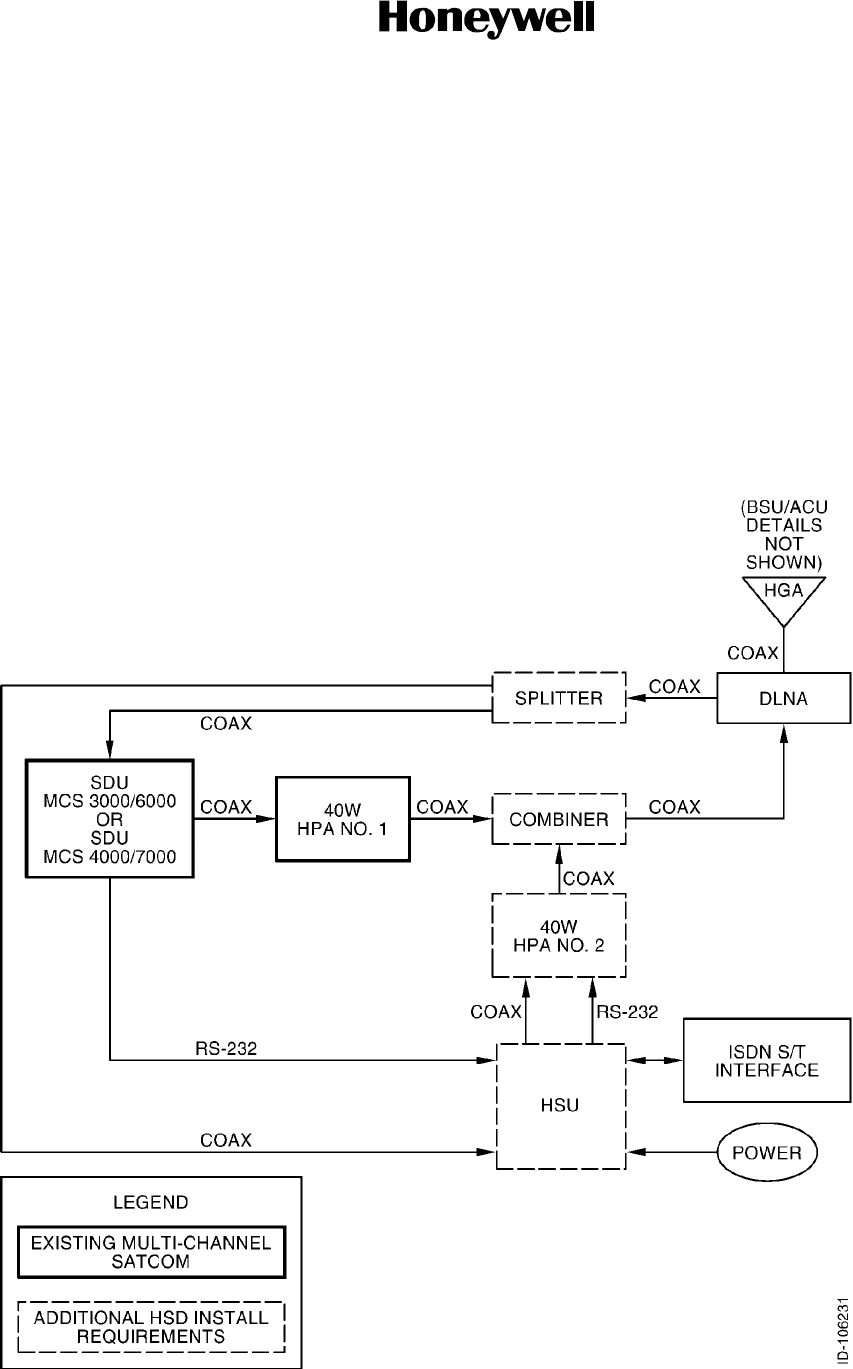
(1) The HS--600 high speed data system provides multi--channel Inmarsat Aero cockpit
and passenger voice, fax, and data, and multi--media mini--M (M4) circuit--mode
services simultaneously. Figure 1-1 shows a block diagram of the high speed data
(HSD) system.
Figure 1-1. High Speed Data System Block Diagram

SYSTEM DESCRIPTION AND INSTALLATION MANUAL
HS--600 High Speed Data System
23--20--31
30 May 2002
Use or disclosure of information on this page is subject to the restrictions in the proprietary notice of this document.
Page 1--2
(2) The HSD system is capable of being integrated with the MCS--3000, MCS--6000,
MCS--4000, and MCS--7000 multi--channel (MCS) satellite communications
(SATCOM) systems with Aero--H/H+ high gain antennas (HGA). The HSD system is
interfaced with its own dedicated 40 W high power amplifier (HPA).
(3) The L--band radio frequency (RF) outputs of the HSD system HPA and the satellite
data unit (SDU)/radio frequency unit (RFU) 40 W HPA is combined with a high power
combiner. The output of the high power combiner drives a common diplexer/low noise
amplifier (DLNA) and a nominal 12 dB gain antenna. The SDU manages the satellite
selection and steers the HGA.
(4) The Aero--H/H+ SDU and HPA requires no hardware or operational software
modifications, and operates without knowledge of the HSD system presence.
However, each SDU used in conjunction with the HSD system will require advance
configuration of its data logging terminal (DLT) parameter settings.
(5) The SDU’s DLT RS--232 port must be configured to transmit the ASCII data given in
Table 1-1, at a rate of approximately 1 Hz, for the functions in Table 1-1 to be
performed in the HSD system (SDU to HSU transmit only).
Table 1-1. SDU DLT RS--232 Port Configuration
Data Function
Satellite Selected Satellite selection
Position (Latitude/Longitude) Spot beam selection
Satellite--Relative Velocity Open--loop Doppler compensation
Current Antenna Gain Antenna gain variation compensation
Log--On Status Status of satellite selected indication (stable or not)
(6) The SDU CMT keystrokes given in Table 1-2 (starting from the main menu) are
required to configure the SDU to broadcast the desired data from its DLT port.
Table 1-2. SDU CMT Keystrokes
Keystroke Description
HBA To logging menu
00020509 <cr> Enter logging word
B1 <cr> Set logging period
C60 <cr> Set heading record frequency
E1 <cr> Select DLT port for output
D1 <cr> Enable logging

SYSTEM DESCRIPTION AND INSTALLATION MANUAL
HS--600 High Speed Data System
23--20--31
30 May 2002
Use or disclosure of information on this page is subject to the restrictions in the proprietary notice of this document.
Page 1--3
(7) The DLT configuration settings remain in effect indefinitely, unless subsequently
manually changed or a factory settings restart is performed. If the SDU in conjunction
with the HSD system is replaced for any reason, the replacement SDU will require its
DLT port to be configured appropriately.
(8) The HSD system controls its HPA through the HPA’s commissioning and
maintenance terminal (CMT) RS--232 input port (HSU to HPA transmit only),
dynamically controlling the transmit RF carrier on/off state as well as the HPA’s
backoff state.
B. Aero--H/H+
(1) Aero--H/H+ is a multi--channel aeronautical system that can operate in both the
Inmarsat--3 global and spot beams using either a fuselage-- or tail--mounted HGA.
The type of antenna and the global/spot beam operation identify the type of service
possible as given in Table 1-3.
Table1-3. TypeofService
Aero
Type Antenna
Global
Beam
Spot
Beam
Voice
9.6
kbps
Voice
4.8
kbps
Secure
Voice 4.8
kbps
Fax
(max)
PC Data
(max)
Packet
Mode
Data
(max)
Aero--H High gain Yes No Yes No Yes 4.8 kbps 2.4 kbps 10.5 kbps
Aero--H+ High gain Yes Yes Yes Yes Yes 4.8/2.4
kbps
2.4 kbps 10.5 kbps
(2) When used within the spot beams, Aero--H+ voice and data rates are lower.
Therefore, it requires less power so that call charges are reduced. All
Honeywell/Thales aeronautical equipment complies with the International Civil
Aviation Organization (ICAO) Agency of the UN requirements for aeronautical safety
services. The equipment can be used for communication, navigation, and
surveillance/air traffic management (CNS/ATM).
C. Inmarsat High Speed Systems
(1) Aero M4 circuit--mode service provides data rates of up to 64 kbps. M4 land earth
stations (LES) serve as gateways to the Public Switched Telephone Network (PSTN)
or the ISDN.
(2) M4 is a companion to, but not a replacement for, an Aero--H system. As
developments of the Mini--M, they do not comply with the ICAO requirements for
aeronautical safety services and cannot be used for CNS/ATM. In other words, they
can only be used for non--safety service data communications.

SYSTEM DESCRIPTION AND INSTALLATION MANUAL
HS--600 High Speed Data System
23--20--31
30 May 2002
Use or disclosure of information on this page is subject to the restrictions in the proprietary notice of this document.
Page 1--4
D. System Performance
(1) Currently, the numbers of simultaneous aeronautical voice and M4 data channels can
only be obtained from theoretical calculations. Using the assumptions given in
Table 1-4, the calculations are given in Table 1-5. The calculations for the total
number of calls are given in Table 1-6 thru Table 1-9.
Table 1-4. Assumptions
Item dB Watts
Gain cell 12 dB
R/T power (10.5 Kbps assumed) 20.4 dBW 109.6 W
R/T power (600 bps assumed) 5.9 dBW 3.9 W
HPA power (same assumed for both) 16.0 dBW 40.0 W
Cable Loss 4.7 dB
Initial HSD channel power 22.5 dBW 177.8 W
Settled HSD channel power 22.5 dBW 177.8 W
Initial 8400 C channel EIRP 14.5 dBW 28.2 W
Settled 8400 C channel EIRP 7.5 dBW 5.6 W
Initial 21000 C channel EIRP 19.5 dBW 89.1 W
Settled 21000 C channel EIRP 13.5 dBW 22.4 W
Table 1-5. Calculations
HGA Gain dBW Total Watts
After R/T 600 bps
(Watts)
AfterR/T10.5Kbps
(Watts)
12 23.3 214.8 210.9 105.2
Table 1-6. Total Number of Calls with Aero--H+ (Spot beam operation) and 10.5 Kbps
Packet Data Rate
M4 HSD Channels 8400 Voice Channels 21000 Voice Channels
15/6 (Note) 0
121
NOTE: MCS 6000 = 5, MCS 7000 = 6

SYSTEM DESCRIPTION AND INSTALLATION MANUAL
HS--600 High Speed Data System
23--20--31
30 May 2002
Use or disclosure of information on this page is subject to the restrictions in the proprietary notice of this document.
Page 1--5
Table 1-7. Total Number of Calls with Aero--H+ (Spot beam operation) and 600 bps Packet
Data Rate
M4 HSD Channels 8400 Voice Channels 21000 Voice Channels
15/6 (Note) 1
105
NOTE: MCS 6000 = 5, MCS 7000 = 6
Table 1-8. Total Number of Calls with Aero--H+ (Global beam operation) and 10.5 Kbps
Packet Data Rate
M4 HSD Channels 8400 Voice Channels 21000 Voice Channels
1 0 1/2
Table 1-9. Total Number of Calls with Aero--H+ (Global beam operation) and 600 bps
Packet Data Rate
M4 HSD Channels 8400 Voice Channels 21000 Voice Channels
105
(2) From these calculations the following points should be made:
(a) There is an increased loss of 3.5 dB, due to the addition of the high power
combiner with the HS--600 installation. It is essential that a 12 dB antenna is
used to be able to support more than one Aero voice channel as well as a
simultaneous Aero M4 HSD.
E. FCC Compliance
(1) This device complies with part 15 of the FCC rules. Operation is subject to the
following two conditions:
•This device may not cause harmful interference.
•This device must accept any interference received, including interference that may
cause undesired operation.

SYSTEM DESCRIPTION AND INSTALLATION MANUAL
HS--600 High Speed Data System
23--20--31
30 May 2002
Use or disclosure of information on this page is subject to the restrictions in the proprietary notice of this document.
Page 1--6
2. System Components
A. General
(1) Table 1-10 gives the component part numbers supplied by Honeywell. Table 1-11
gives components that are necessary, but are not supplied by Honeywell.
Table 1-10. Components Supplied by Honeywell
Component Model No. Honeywell Part No.
High Speed Data Unit HS--600 7519300--901
High Speed Combiner Assembly -- 7519340--901
RF Power Splitter -- 7519349--1
High Power Amplifier (40 W) HP--600 7516250--XX050 (Note)
NOTE: The HSD system requires an additional HPA. Only an HPA, Part No. 7516250--XX050 (software Mod F) can be
used with the HS--600 system.
Table 1-11. Components/Parts Not Supplied by Honeywell
Component/Part Comments
HSU Mounting Tray (4--MCU size unit) ARINC 600 4--MCU Mount, cooling air required.
(Installer to supply mount.)
HSU Mounting Tray (8--MCU size unit) ARINC 600 8--MCU Mount, cooling air required.
(Installer to supply mount.)
NOTE: Refer to paragraph 3.D. and Table 1-15 in this section for mounting tray information.

SYSTEM DESCRIPTION AND INSTALLATION MANUAL
HS--600 High Speed Data System
23--20--31
30 May 2002
Use or disclosure of information on this page is subject to the restrictions in the proprietary notice of this document.
Page 1--7
3. Component Descriptions
A. HS--600 High Speed Data Unit (HSU)
(1) The HSU is designed to perform reliably under field conditions and provide ease of
maintenance when required. The HSU has a modular design to permit easy
replacement of each circuit card assembly (CCA). All CCAs are built to standards that
qualify them for both airline and business aircraft usage.
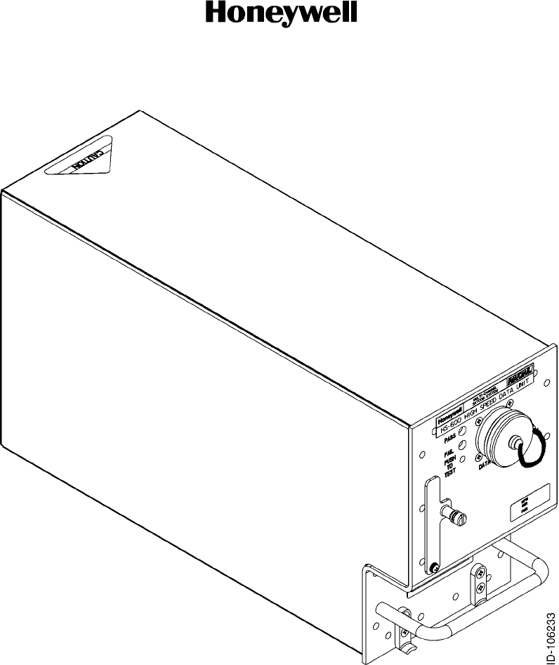
(2) The HSU is packaged as a 4 modular concept unit (4--MCU). The mechanical chassis
is constructed of aluminum alloy sheet metal. The HSU requires external cooling air
in accordance with ARINC 600 or ARINC 404 to maintain the highest possible
mean--time--between--failures (MTBF). In installations where this is not available, a
mounting tray with an integral fan is required. Refer to Table 1-15. The HSU is shown
in Figure 1-2.
(3) Table 1-12 gives the leading particulars for the HSU and Table 1-13 gives the
DO--160D categories that this equipment meets or exceeds.
SYSTEM DESCRIPTION AND INSTALLATION MANUAL
HS--600 High Speed Data System
23--20--31
30 May 2002
Use or disclosure of information on this page is subject to the restrictions in the proprietary notice of this document.
Page 1--8
Figure 1-2. HS--600 HSU

SYSTEM DESCRIPTION AND INSTALLATION MANUAL
HS--600 High Speed Data System
23--20--31
30 May 2002
Use or disclosure of information on this page is subject to the restrictions in the proprietary notice of this document.
Page 1--9
Table 1-12. HS--600 Leading Particulars
Characteristic Specification
Dimensions (maximum):
•Length ................................
•Width .................................
•Height ................................
7.64 in. (194.06 mm)
4.90 in. (124.46 mm)
15.26 in. (387.60 mm)
Weight (maximum) ....................... 11.84lb(5.37kg)
Power requirements (AC) (Note):
•Nominal ............................... 115 V rms, 400 Hz
•Maximum ............................. 134 V rms, 480 Hz
•Minimum .............................. 97 V rms, 320 Hz
Power requirements (DC) Note):
•Nominal ............................... 27.5 V dc
•Maximum ............................. 32.2 V dc
•Minimum .............................. 20.5 V dc
PowerConsumption ...................... 25 W nominal, 40 W maximum
Cooling Requirements .................... Select tray from Table 1-15
Connector P1 (Rear) ...................... Radiall Part No. 620--600--237
Mating Connector (P1) .................... Radiall Part No. 620--600--238
•22AWGContacts ...................... Radiall Part No. 620--200
•20AWGContacts ...................... Radiall Part No. 620--310
•16AWGContacts ...................... Radiall Part No. 620--330
•12AWGContacts ...................... Radiall Part No. 620--340
•Size5CoaxContacts ................... Radiall Part No. 620--021
Mounting ................................ Tray, ARINC 600 4--MCU Size
Circuit Breaker Ratings:
•115VacCircuitBreaker ................ 2 Amp typical
•28VdcCircuitBreaker ................. 7.5 Amp typical
UserInterface(ISDNS/T) ................. ITU--T 1.430 (S/T interface)
DSS1/EuroISDN
Environmental ........................... Unit must be installed inside pressurized bulkhead (cabin).

SYSTEM DESCRIPTION AND INSTALLATION MANUAL
HS--600 High Speed Data System
23--20--31
30 May 2002
Use or disclosure of information on this page is subject to the restrictions in the proprietary notice of this document.
Page 1--10
Table 1-13. DO--160D Environmental Categories
Description Category
Temperature and Altitude XX
In--Flight Loss of Cooling X
Temperature Variation X
Humidity X
Shock B
Vibration SB2
Explosion Proofness X
Waterproofness X
Fluids Susceptibility X
Sand and Dust X
Fungus Resistance X
Salt Spray X
Magnetic Effect X
Power Input X
Voltage Spike X
Audio Frequency Susceptibility X
Induced Signal Susceptibility X
Radio Frequency (RF) Susceptibility XXX
Emission of RF Energy M
Lightning Indirect Effects XXXX
Lightning Direct Effects X
Icing X
Electrostatic Discharge (ESD) X

SYSTEM DESCRIPTION AND INSTALLATION MANUAL
HS--600 High Speed Data System
23--20--31
30 May 2002
Use or disclosure of information on this page is subject to the restrictions in the proprietary notice of this document.
Page 1--11
(4) Table 1-14 gives a description of the HSU front panel lights during various HSU
conditions. The PUSH TO TEST switch on the front panel of the HSU is not
operational.
Table 1-14. HSU Front Panel Light Description
Condition Description
Power Up Both PASS and FAIL lights are on steady.
Software Boot Complete Both PASS and FAIL lights are off. The lights should go off within 30
seconds of power up.
Receiver Activity If the SDU is logged on, the HS--600 is able to pick an LES to listen to,
similar to the P--channel for the MCS. Once the receiver synchronizes on
this time division multiplex (TDM) channel, the green PASS light flashes.
The light flashes for each correctly received signal unit (SU). This should
occur within 2 minutes of power up, if the SDU is logged on, or within 30
seconds after the SDU log--on, if beyond the initial 2 minutes.
Since the flash rate is related to the received SUs, the rate varies as time
goes on; it could even stop flashing with the light on or off. However, during
an HSD call, SUs are received at a high rate, so the green PASS light will
flash rapidly, appearing to be almost steady on.
Failure The FAIL light will be on if any error occurs.
SYSTEM DESCRIPTION AND INSTALLATION MANUAL
HS--600 High Speed Data System
23--20--31
30 May 2002
Use or disclosure of information on this page is subject to the restrictions in the proprietary notice of this document.
Page 1--12
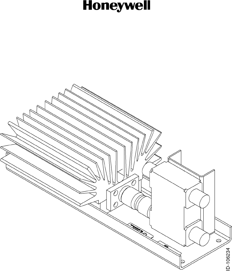
B. High Speed Combiner Assembly
(1) The high speed combiner assembly combines the signals from both HPAs which are
then sent to the DLNA. Figure 1-3 shows the high speed combiner assembly.
Figure 1-3. High Speed Combiner Assembly
SYSTEM DESCRIPTION AND INSTALLATION MANUAL
HS--600 High Speed Data System
23--20--31
30 May 2002
Use or disclosure of information on this page is subject to the restrictions in the proprietary notice of this document.
Page 1--13
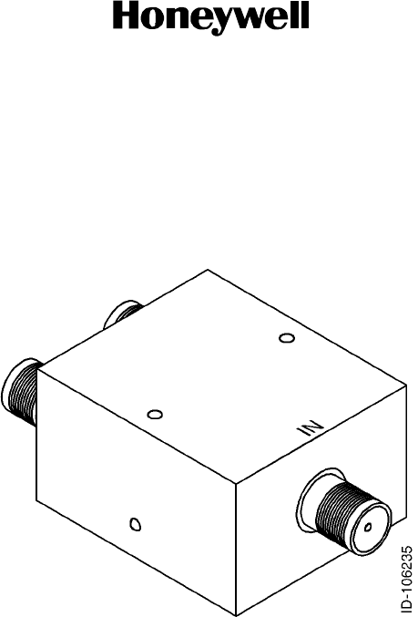
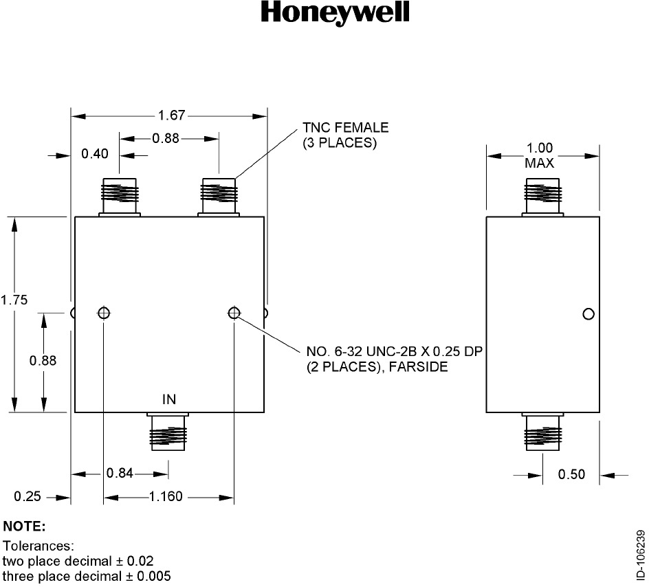
C. RF Power Splitter
(1) The RF power splitter divides the signal from the DLNA which is then sent to the SDU
and HSU. The unit weight is 2.5 oz. (70.87 grams). Figure 1-4 shows the RF power
splitter.
Figure 1-4. RF Power Splitter
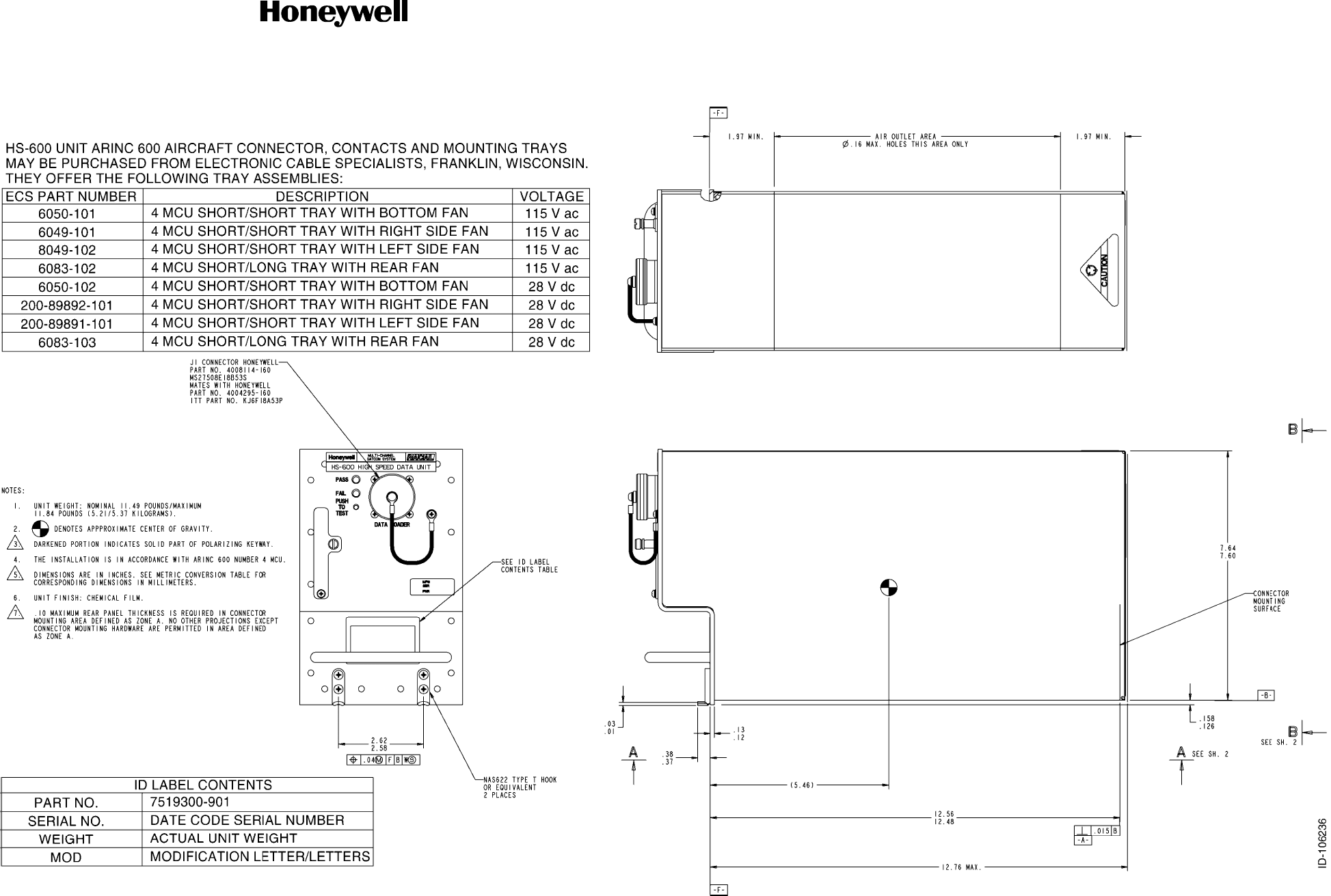
D. HSU Mounting Tray
(1) The HS--600 HSU ARINC 600 connector, contacts, and mounting trays can be
purchased from ECS or EMTEQ. The addresses for ECS and EMTEQ are as follows:
Electronic Cable Specialists
5300 W. Franklin Drive
Franklin, WI 53132
U.S.A.
Telephone: (414) 421--5300
Fax: (414) 421--5301
EMTEQ
S84 W. 18693 Enterprise Drive
Muskego, WI 53150
U.S.A.
Telephone: (262) 679--6170 / 1--888--679--6170

SYSTEM DESCRIPTION AND INSTALLATION MANUAL
HS--600 High Speed Data System
23--20--31
30 May 2002
Use or disclosure of information on this page is subject to the restrictions in the proprietary notice of this document.
Page 1--14
(2) Table 1-15 gives a list of HSU mounting trays available through ECS. Contact
EMTEQ for a list of HSU mounting trays available.
Table 1-15. HSU Mounting Trays
ECS Part No. Description Voltage
6050--101 4 MCU S/S tray with bottom fan 115 V ac
6049--101 4 MCU S/S tray with right side fan 115 V ac
6049--102 4 MCU S/S tray with left side fan 115 V ac
6083--102 4MCUS/Ltraywithrearfan 115 V ac
6050--102 4 MCU S/S tray with bottom fan 28 V dc
200--89891--101 4 MCU S/S tray with left side fan 28 V dc
200--89892--101 4 MCU S/S tray with right side fan 28 V dc
6083--103 4MCUS/Ltraywithrearfan 28 V dc
6292--101 8 MCU S/S standard tray 115 V ac
6288--101 8MCUS/Strayw/bottomfan 115 V ac
6290--101 8 MCU S/S tray w/left side fan 115 V ac
6284--101 8 MCU S/S tray w/right side fan 115 V ac
6286--101 8 MCU S/L standard tray 115 V ac

MECHANICAL
INSTALLATION

SYSTEM DESCRIPTION AND INSTALLATION MANUAL
HS--600 High Speed Data System
23--20--31
30 May 2002
Use or disclosure of information on this page is subject to the restrictions in the proprietary notice of this document.
Page 2--1
SECTION 2
MECHANICAL INSTALLATION
1. Overview
A. General
(1) This section contains information on how and where to mount the HSU, combiner,
and splitter. Figure 2-1 shows the HSU dimensions. Figure 2-2 shows the dimensions
and mounting hole dimensions of the combiner.
B. Equipment and Materials
(1) For new HSU installations, refer to Table 1-11 for mounting tray information. See the
applicable outline and installation diagram in this section for additional mounting
information.
2. Mechanical Installation Design
A. HS--600 HSU Provisions
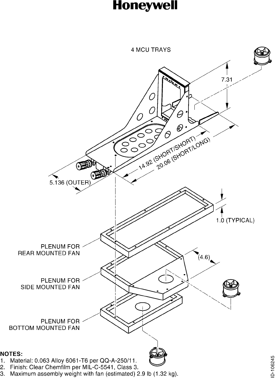
(1) Mechanical installation data for the HS--600 HSU is shown in Figure 2-1. The HSU is
mounted in an ARINC 600 4--MCU mounting tray. The HSU requires external cooling
air to maintain the highest possible MTBF. A mounting tray with an integral fan is
required. Select a mounting tray from Table 1-15. Figure 2-4 shows typical 4--MCU
tray assemblies with a fan.
(2) The location of the mounting tray allows the interface cabling to other units to be as
short as possible. The location must give protection against rain, condensation,
solvents, and hydraulic fluid. The mounting tray must be electrically bonded to the
aircraft frame by a low resistance path of less than 0.1 ohm.
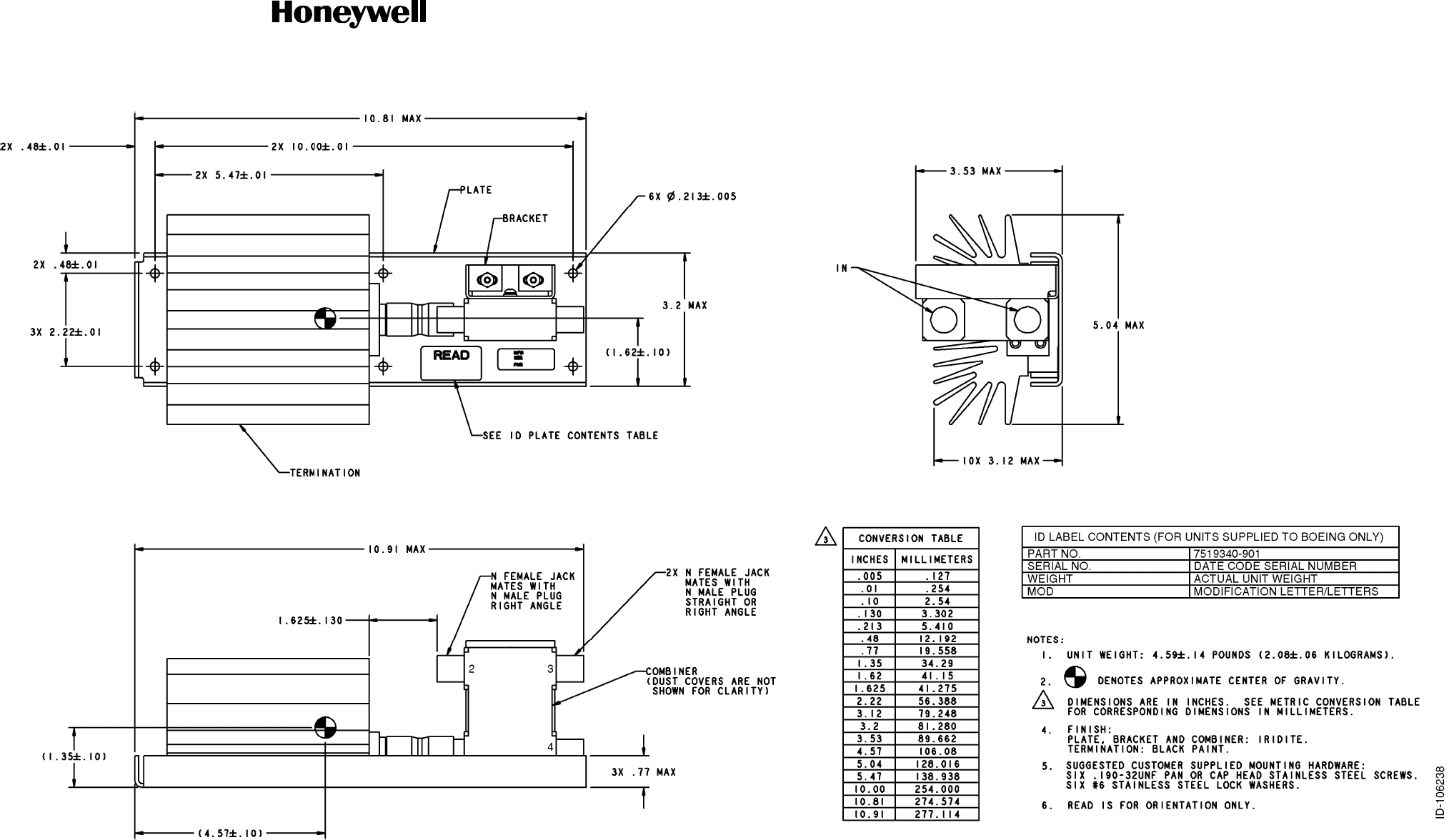
B. High Speed Combiner Assembly
(1) Mechanical installation data for the combiner is shown in Figure 2-2.
C. RF Power Splitter Provisions
(1) Mechanical installation data for the splitter is shown in Figure 2-3.

SYSTEM DESCRIPTION AND INSTALLATION MANUAL
HS--600 High Speed Data System
23--20--31
30 May 2002
Use or disclosure of information on this page is subject to the restrictions in the proprietary notice of this document.
Page 2--2
Blank Page
SYSTEM DESCRIPTION AND INSTALLATION MANUAL
HS--600 High Speed Data System
23--20--31
30 May 2002
Use or disclosure of information on this page is subject to the restrictions in the proprietary notice of this document.
Page 2--3/2--4
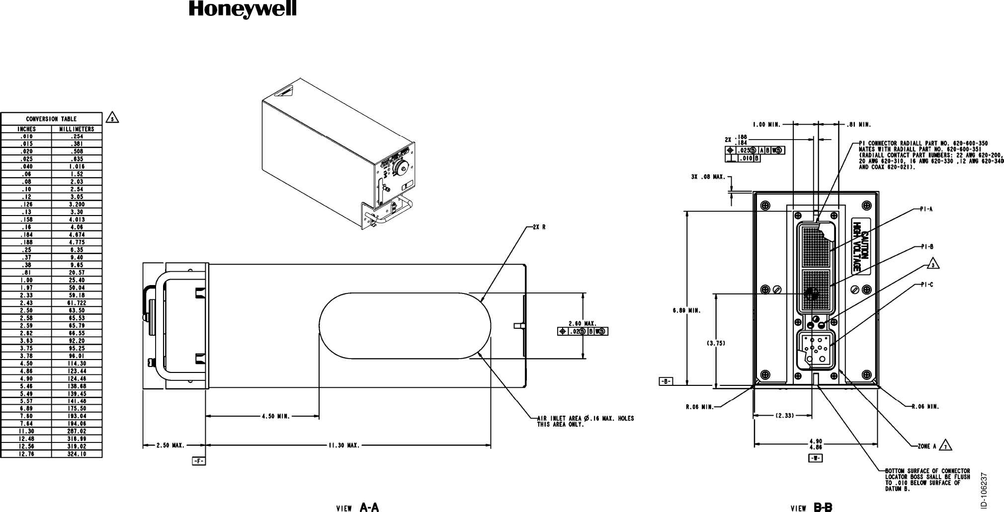
Figure 2-1 (Sheet 1). HSU Outline and Installation Diagram
SYSTEM DESCRIPTION AND INSTALLATION MANUAL
HS--600 High Speed Data System
23--20--31
30 May 2002
Use or disclosure of information on this page is subject to the restrictions in the proprietary notice of this document.
Page 2--5/2--6
Figure 2-1 (Sheet 2). HSU Outline and Installation Diagram
SYSTEM DESCRIPTION AND INSTALLATION MANUAL
HS--600 High Speed Data System
23--20--31
30 May 2002
Use or disclosure of information on this page is subject to the restrictions in the proprietary notice of this document.
Page 2--7/2--8
Figure 2-2. High Speed Combiner Outline and Installation Diagram
SYSTEM DESCRIPTION AND INSTALLATION MANUAL
HS--600 High Speed Data System
23--20--31
30 May 2002
Use or disclosure of information on this page is subject to the restrictions in the proprietary notice of this document.
Page 2--9
Figure 2-3. RF Power Splitter Outline Diagram
SYSTEM DESCRIPTION AND INSTALLATION MANUAL
HS--600 High Speed Data System
23--20--31
30 May 2002
Use or disclosure of information on this page is subject to the restrictions in the proprietary notice of this document.
Page 2--10
Figure 2-4. Typical Dimensions for 4--MCU Tray Assemblies
SYSTEM DESCRIPTION AND INSTALLATION MANUAL
HS--600 High Speed Data System
23--20--31
30 May 2002
Use or disclosure of information on this page is subject to the restrictions in the proprietary notice of this document.
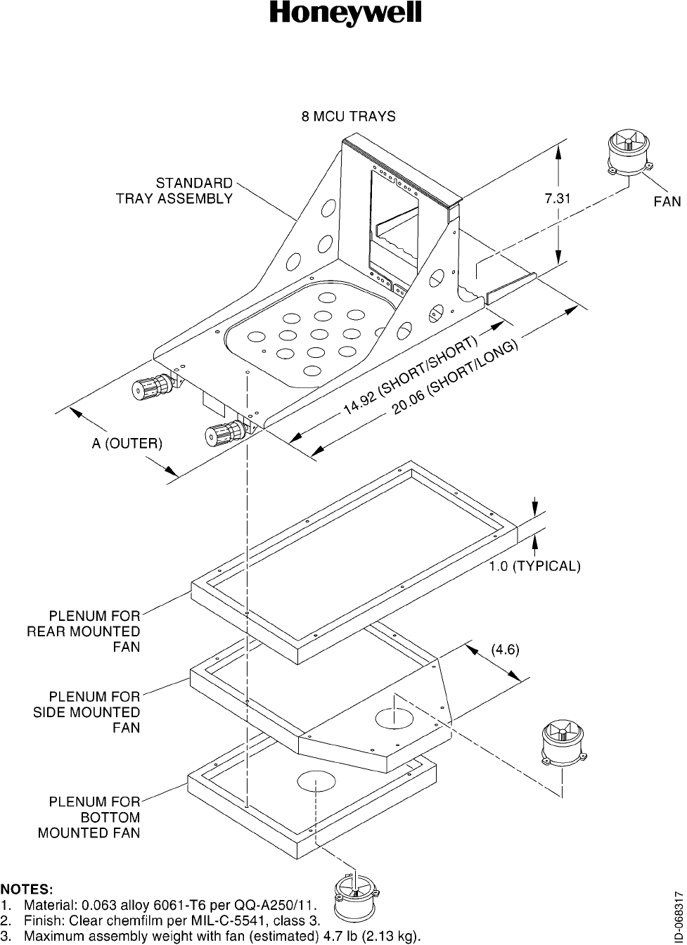
Page 2--11
Figure 2-5. Typical Dimensions for 8--MCU Tray Assemblies

SYSTEM DESCRIPTION AND INSTALLATION MANUAL
HS--600 High Speed Data System
23--20--31
30 May 2002
Use or disclosure of information on this page is subject to the restrictions in the proprietary notice of this document.
Page 2--12
Blank Page

ELECTRICAL
INSTALLATION

SYSTEM DESCRIPTION AND INSTALLATION MANUAL
HS--600 High Speed Data System
23--20--31
30 May 2002
Use or disclosure of information on this page is subject to the restrictions in the proprietary notice of this document.
Page 3--1
SECTION 3
ELECTRICAL INSTALLATION
1. Overview
A. General
(1) This section gives electrical installation procedures, power distribution, and
interconnect information for the HSU, combiner, and splitter.
(2) Procedures for proper shield, power, and signal grounding are also provided in this
section. In addition, procedures for the various buses are included.
B. Equipment and Materials
(1) See leading particulars table for a list of mating connectors required to do the
electrical installation.
2. Electrical Installation Procedure
A. General
(1) The information necessary to provide the electrical interconnects is contained in the
following paragraphs.
B. Power Requirements
(1) AC Power -- The aircraft ac power inverters must supply single phase 115 V ac
(min 97, max 134 V ac) 400±80 Hz sine wave with a maximum total harmonic
distortion of 5%. Under all load conditions, amplitude modulation of the power supply
will not exceed 2% at any frequency. (Percent modulation is defined as one--half of
the peak--to--peak modulation envelope divided by the carrier amplitude and
multiplied by 100.)
(2) DC Power -- The aircraft dc power supply must be 28 V dc (nominal). The normal
minimum and maximum voltages permitted are 20.5 and 32.2 V dc respectively.
(3) Power supply to the HSU -- The voltage level of the power supplied to the HSU is
important in this installation. The potential is the difference between the power pins
and power ground pins at the line replaceable unit (LRU). Excessive voltage drops in
the power wire(s) and power ground wire(s) cause one or more of the following
conditions:
•The LRU draws additional current from the aircraft supply system.
•Since the LRU is drawing more current, it produces more heat and more heat
causes a lower LRU MTBF.
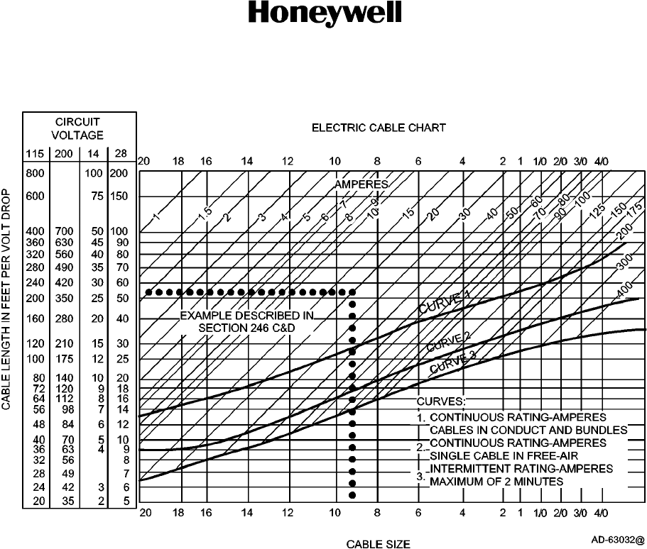
(4) The recommended maximum total combined voltage drop (voltage drop of the power
wire[s] plus voltage drop of the power ground wire[s]) is 1.0 V. Voltage drop is a
function of current and resistance (resistance in this case is a function of wire gauge
and wire length). See Figure 3-1 for determining proper wire gauge for LRU power
and power ground wires.
SYSTEM DESCRIPTION AND INSTALLATION MANUAL
HS--600 High Speed Data System
23--20--31
30 May 2002
Use or disclosure of information on this page is subject to the restrictions in the proprietary notice of this document.
Page 3--2
Figure 3-1. Electric Cable Chart
C. Ground Requirements
(1) General
(a) Proper grounding is a key factor in ensuring proper system operation under
normal conditions, high intensity radiated electromagnetic frequencies (HIRF),
and lightning environments. You must obey this section to satisfy these
requirements.
NOTE: HIRF and lightning requirements dictate that the shielded wires meet
the requirements of paragraph 2.C.(3). Installation of this system into
aircraft manufactured prior to the FAA requirements adheres to these
practices whenever feasible.
(2) Chassis Grounding
(a) All rack mount/remote mount units are electrically bonded to the airframe. This is
done by making sure the mating surfaces between the LRU mounting tray (or
LRU mounting feet if a tray is not used) provide a low impedance (< 0.1 Ω)
electrical path.
SYSTEM DESCRIPTION AND INSTALLATION MANUAL
HS--600 High Speed Data System
23--20--31
30 May 2002
Use or disclosure of information on this page is subject to the restrictions in the proprietary notice of this document.
Page 3--3
(b) The mating surfaces must be free of all paint and other non--conductive
elements and are burnished to ensure a good bond. If the aircraft mating surface
is not conductive, a bonding strap of a least 1/4--inch wide (preferably 1/2--inch
wide) tin coated copper braid can be used between the LRU mounting tray (or
LRU itself if a tray is not used) and the nearest airframe grounding point.
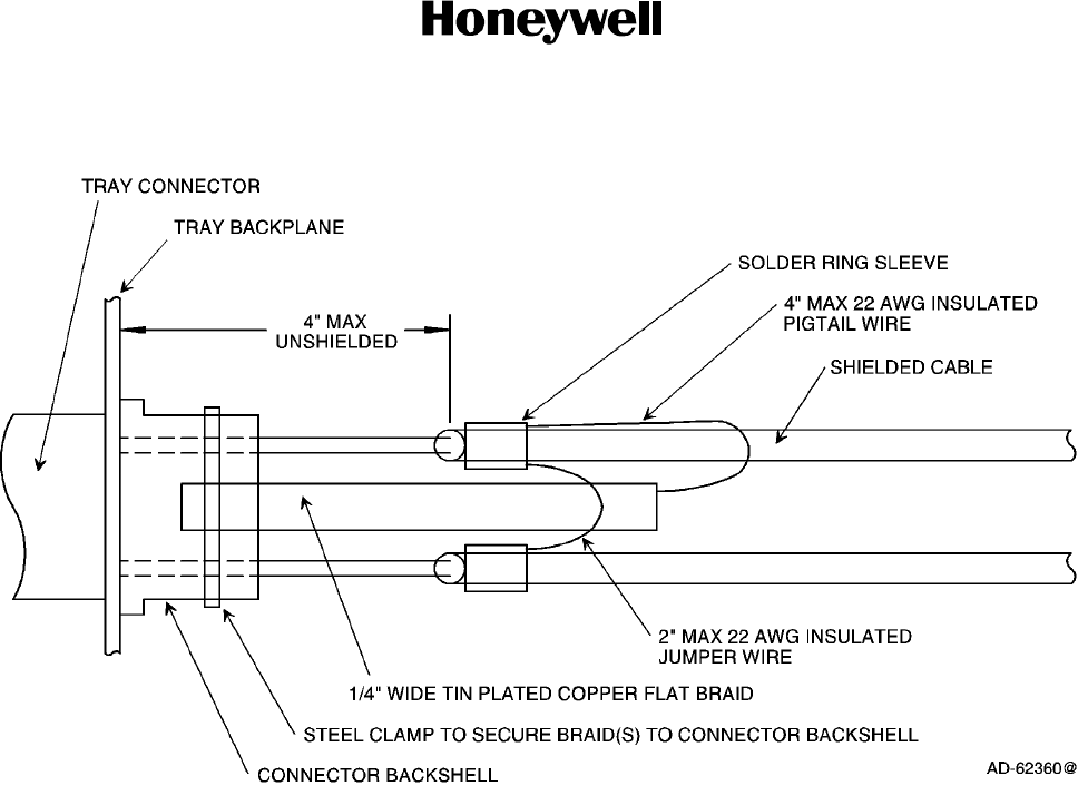
(3) Shield Grounds
(a) The shield wires in the HSU have the shield grounded at both ends. This is
called multi--point grounding and is specified to minimize the adverse effects of
HIRF and lightning.
(b) The shield must not be connected to any LRU or bulkhead connector pin.
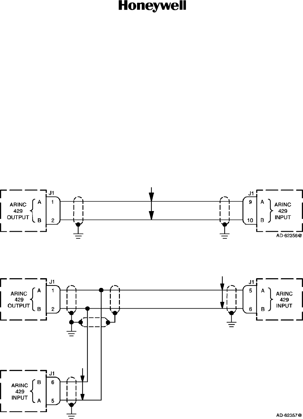
(c) Examples of multi--point shield grounding methods are shown in Figure 3-2 and
Figure 3-3. The shield grounding method for rack mount units is detailed in
Figure 3-4. This is the preferred shield grounding method for the HSU rack
mount unit.
Figure 3-2. Example 1, Multi--point Shield Ground
Figure 3-3. Example 2, Multi--point Shield Ground
SYSTEM DESCRIPTION AND INSTALLATION MANUAL
HS--600 High Speed Data System
23--20--31
30 May 2002
Use or disclosure of information on this page is subject to the restrictions in the proprietary notice of this document.
Page 3--4
Figure 3-4. Shield Grounding Example for Rack Mount Connectors
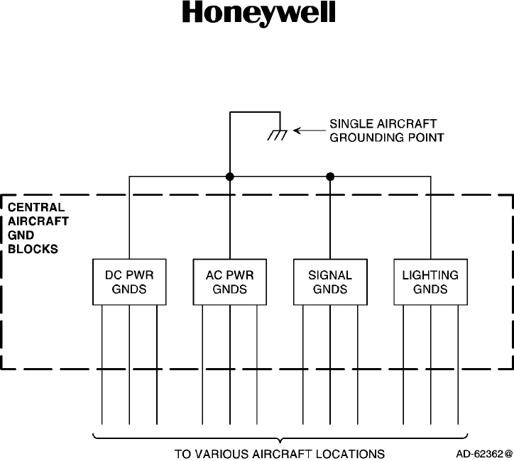
(4) Power/Signal Grounds
(a) All dc power grounds are tied together; all ac power grounds are tied together; all
signal grounds are tied together; and all lighting grounds are tied together. DC
power, ac power, signal and light ground groups are then tied together at a single
point and connected to the airframe. Figure 3-5 shows this aircraft grounding
method.
NOTE: It is very important this grounding technique be adhered to. Do not tie
the various ground wires to multiple aircraft frame points and depend on
the aircraft structure to supply a low impedance path for the individual
grounds. Only chassis grounds and shield grounds are grounded at
multiple points in the aircraft.
SYSTEM DESCRIPTION AND INSTALLATION MANUAL
HS--600 High Speed Data System
23--20--31
30 May 2002
Use or disclosure of information on this page is subject to the restrictions in the proprietary notice of this document.
Page 3--5
Figure 3-5. Aircraft Grounding
(b) Because signal grounds are low currents, multiple signal grounds can be
connected to remote aircraft terminal blocks other than the central grounding
blocks as long as these remote terminal blocks are isolated from ground. The
various remote signal ground blocks must all be grounded only at the aircraft
central grounding point. If 10 signal grounds are connected to a remote terminal
block, a minimum of one grounding wire must be run from this terminal block to
the aircraft central grounding point.
3. Electrical Installation
A. HS--600 HSU
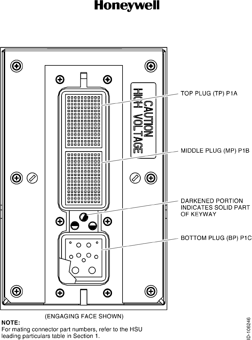
(1) The HSU rear ARINC 600 connector layout is shown in Figure 3-6. The contact
arrangement for the various connector plugs are given in Table 3-1, Table 3-2, and
Figure 3-7. Figure 3-8 shows the connector pin layout for the DATA LOADER
connector located on the front of the HSU. The system interface is shown in
Figure 3-9. See Figure 3-10 for the HSU interconnect information.
SYSTEM DESCRIPTION AND INSTALLATION MANUAL
HS--600 High Speed Data System
23--20--31
30 May 2002
Use or disclosure of information on this page is subject to the restrictions in the proprietary notice of this document.
Page 3--6
Figure 3-6. HSU ARINC 600 Connector (P1) Pin Layout

SYSTEM DESCRIPTION AND INSTALLATION MANUAL
HS--600 High Speed Data System
23--20--31
30 May 2002
Use or disclosure of information on this page is subject to the restrictions in the proprietary notice of this document.
Page 3--7
Table 3-1. Contact Arrangements for P1--A Top Insert, HSU ARINC 600 Connector
A B C D E F G H J K
1RSVD
APM
POWER
RSVD
APM
GND
RSVD
APM
ENABLE
1#
RSVD
APM
ENABLE
2#
RSVD
APM
OUT CLK
RSVD
POTS
RING
ASYNC
CTS
RSVD
APM
OUT
DATA
RSVD
APM IN
DATA
RSVD
APM WR
PROT 1#
2RSVD
APM WR
PROT 2#
RSVD
APM
RSVD
RSVD
POTS
TIP
ASYNC
TXD
10BT
RX--
ASYNC
DCD
ASYNC
CTS SIG
GND
ISDNS/T
RX+
10BT
RX+
RSVD
SPARE
257 GND
3DISC
SPARE A
DISC TX
INH
RSVD
SPARE
D/L 18
RSVD
SPARE
D/L 17
RSVD
SPARE
D/L 16
RSVD
SPARE
D/L 15
RSVD
SPARE
174
RSVD
SPARE
258
CHASSIS
GND GC
2
ISDNS/T
TX+
4CHASSIS
GND GC
10
ASYNC
RI SIG
GND
ASYNC
DCD SIG
GND
ASYNC
TXD SIG
GND
10BT
TX--
ASYNC
RI
HTCE
TXD
DISC DM
RST*
ISDNS/T
TX--
10BT
TX+
5DISC
SPARE B
ASYNC
DTR
CHASSIS
GND GC
3
ISDNS/T
RX--
HTCE
TXD SIG
GND
ASYNC
RTS
HTCE
RXD SIG
GND
HTCE
RXD
RSVD
SPARE
198
ISDNU
TIP
6ASYNC
RXD SIG
GND
ASYNC
DTR SIG
GND
ASYNC
DSR
RSVD
SPARE
176
RSVD
SPARE
175
MAINT
232 RXD
MAINT
232 TXD
MAINT
232 TXD
SIG GND
MAINT
232 RXD
SIG GND
CHASSIS
GND GC
1
7ASYNC
RXD
ISDNU
RING
ASYNC
DSR SIG
GND
ASYNC
RTS SIG
GND
RSVD
SPARE
199
RSVD
SPARE
212
RSVD
SPARE
103
RSVD
SPARE
115
CHASSIS
GND
RSVD
VHF
KEYLINE
GND
8RSVD
SPARE
LO 26
RSVD
SPARE
HI 26
RSVD
SPARE
LO 27
RSVD
SPARE
HI 27
RSVD
SPARE
HI 11
RSVD
SPARE
LO 11
RSVD
SPARE
36
RSVD
SPARE
85
RSVD
SPARE
HI 4
RSVD
SPARE
LO 4
9RSVD
VHF
AUDIO
OUT HI
RSVD
VHF
AUDIO
OUT LO
RSVD
VHF
AUDIO
IN HI
RSVD
VHF
AUDIO
IN LOW
RSVD
SPARE
HI 13
RSVD
SPARE
LO 13
RSVD
SPARE
161
RSVD
SPARE
162
RSVD
SPARE
HI 9
RSVD
SPARE
LO 9
10 RSVD
SPARE
29
RSVD
SPARE
78
RSVD
SPARE
19
RSVD
SPARE
68
RSVD
SPARE
43
RSVD
SPARE
92
RSVD
SPARE
107
RSVD
SPARE
120
RSVD
SPARE
HI 1
RSVD
SPARE
LO 1
11 RSVD
SPARE
HI 7
RSVD
SPARE
LO 7
RSVD
SPARE
197
CHASSIS
GND
RSVD
SPARE
HI 8
RSVD
SPARE
LO 8
RSVD
SPARE
HI 6
RSVD
SPARE
LO 6
RSVD
SPARE
265
CHASSIS
GND
12 RESVD
SPARE
266
RSVD
SPARE
110
RSVD
SPARE
123
RSVD
SPARE
34
RSVD
SPARE
83
RSVD
SPARE
202
RSVD
SPARE
201
RSVD
SPARE
203
RSVD
SPARE
204
CHASSIS
GND
13 RSVD
SPARE
HI 5
RSVD
SPARE
LO 5
RSVD
SPARE
207
RSVD
SPARE
HI 14
RSVD
SPARE
LO 14
RSVD
SPARE
HI 12
RSVD
SPARE
LO 12
RSVD
SPARE
105
RSVD
SPARE
118
RSVD
SPARE
267
14 RSVD
SPARE
39
RSVD
SPARE
88
RSVD
SPARE
40
RSVD
SPARE
89
RSVD
SPARE
195
RSVD
SPARE
196
RSVD
SPARE
268
RSVD
SPARE
23
RSVD
SPARE
72
RSVD
SPARE
186
15 RSVD
SPARE
177
RSVD
SPARE
178
RSVD
SPARE
179
RSVD
SPARE
180
RSVD
SPARE
181
RSVD
SPARE
182
RSVD
SPARE
183
RSVD
SPARE
184
RSVD
SPARE
185
CHASSIS
GND

SYSTEM DESCRIPTION AND INSTALLATION MANUAL
HS--600 High Speed Data System
23--20--31
30 May 2002
Use or disclosure of information on this page is subject to the restrictions in the proprietary notice of this document.
Page 3--8
Table 3-2.
Contact Arrangements for P1--B Top Insert, HSU ARINC 600 Connector
A B C D E F G H J K
1RSVD
SPARE
229
RSVD
SPARE
230
RSVD
SPARE
231
RSVD
SPARE
232
RSVD
SPARE
233
RSVD
SPARE
234
RSVD
SPARE
235
RSVD
SPARE
236
RSVD
SPARE
237
CHASSIS
GND
2RSVD
SPARE
187
RSVD
SPARE
188
RSVD
SPARE
189
RSVD
SPARE
190
RSVD
SPARE
191
RSVD
SPARE
192
RSVD
SPARE
193
RSVD
SPARE
194
RSVD
SPARE
238
RSVD
SPARE
239
3RSVD
SPARE
LO 24
RSVD
SPARE
HI 24
RSVD
SPARE
LO 25
RSVD
SPARE
HI 25
RSVD
SPARE
HI 17
RSVD
SPARE
LO 17
RSVD
SPARE
LO 28
RSVD
SPARE
HI 28
RSVD
SPARE
LO 29
RSVD
SPARE
HI 29
4RSVD
SPARE
240
RSVD
SPARE
241
RSVD
SPARE
46
RSVD
SPARE
95
RSVD
SPARE
242
RSVD
SPARE
243
RSVD
SPARE
244 GND
RSVD
SPARE
245
RSVD
SPARE
246
RSVD
SPARE
247 GND
5RSVD
SPARE
44
RSVD
SPARE
93
RSVD
SPARE
248
CHASSIS
GND RSVD
SPARE
24
RSVD
SPARE
73
RSVD
SPARE
248
RSVD
SPARE
250
RSVD
SPARE
251
RSVD
SPARE
252 GND
6RSVD
SPARE
25
RSVD
SPARE
74
RSVD
SPARE
HI 3
RSVD
SPARE
LO 3
RSVD
SPARE
31
RSVD
SPARE
80
RSVD
SPARE
HI 18
RSVD
SPARE
LO 18
RSVD
SPARE
41
RSVD
SPARE
90
7RSVD
SPARE
HI 19
RSVD
SPARE
LO 19
RSVD
SPARE
32
RSVD
SPARE
81
RSVD
SPARE
253
RSVD
SPARE
HI 2
RSVD
SPARE
LO 2
CHASSIS
GND RSVD
SPARE
15
RSVD
SPARE
64
8RSVD
SPARE
42
RSVD
SPARE
91
RSVD
SPARE
27
RSVD
SPARE
76
RSVD
SPARE
47
RSVD
SPARE
96
RSVD
SPARE
38
RSVD
SPARE
87
RSVD
SPARE
35
RSVD
SPARE
84
9RSVD
SPARE
HI 15
RSVD
SPARE
LO 15
RSVD
SPARE
173
RSVD
SPARE
200
RSVD
SPARE
HI 16
RSVD
SPARE
163
RSVD
SPARE
164
RSVD
SPARE
LO 16
RSVD
SPARE
206
RSVD
SPARE
208
10 RSVD
SPARE
33
RSVD
SPARE
82
RSVD
SPARE
37
RSVD
SPARE
86
RSVD
SPARE
48
RSVD
SPARE
97
RSVD
SPARE
20
RSVD
SPARE
69
RSVD
SPARE
106
RSVD
SPARE
119
11 RSVD
SPARE
108
RSVD
SPARE
121
RSVD
SPARE
9
RSVD
SPARE
58
RSVD
SPARE
10
RSVD
SPARE
59
RSVD
SPARE
D/L 36
RSVD
SPARE
D/L 35
RSVD
SPARE
D/L 30
RSVD
SPARE
D/L 29
12 RSVD
SPARE
104
RSVD
SPARE
117
RSVD
SPARE
7
RSVD
SPARE
56
RSVD
SPARE
101
RSVD
SPARE
113
RSVD
SPARE
8
RSVD
SPARE
57
RSVD
SPARE
3
RSVD
SPARE
52
13 RSVD
SPARE
28
RSVD
SPARE
27
RSVD
SPARE
23
RSVD
SPARE
22
CHASSIS
GND RSVD
SPARE
254
RSVD
SPARE
4
RSVD
SPARE
53
RSVD
SPARE
14
RSVD
SPARE
63
14 RSVD
SPARE
2
RSVD
SPARE
51
RSVD
SPARE
12
RSVD
SPARE
61
RSVD
SPARE
1
RSVD
SPARE
50
RSVD
SPARE
6
RSVD
SPARE
55
RSVD
SPARE
13
RSVD
SPARE
62
15 RSVD
SPARE
255
RSVD
SPARE
256
RSVD
SPARE
109
RSVD
SPARE
122
RSVD
SPARE
99
RSVD
SPARE
111
RSVD
SPARE
102
RSVD
SPARE
114
RSVD
SPARE
5
RSVD
SPARE
54
SYSTEM DESCRIPTION AND INSTALLATION MANUAL
HS--600 High Speed Data System
23--20--31
30 May 2002
Use or disclosure of information on this page is subject to the restrictions in the proprietary notice of this document.
Page 3--9
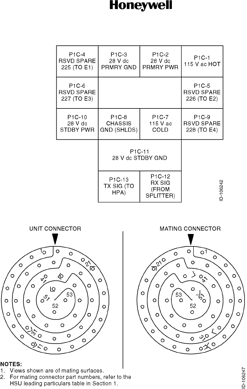
Figure 3-7. Contact Arrangements for P1--C Bottom Insert, HSU ARINC 600 Connector
Figure 3-8. HSU Data Loader Connector (J1) Pin Layout
SYSTEM DESCRIPTION AND INSTALLATION MANUAL
HS--600 High Speed Data System
23--20--31
30 May 2002
Use or disclosure of information on this page is subject to the restrictions in the proprietary notice of this document.
Page 3--10
Figure 3-9. RF System Interface
SYSTEM DESCRIPTION AND INSTALLATION MANUAL
HS--600 High Speed Data System
23--20--31
30 May 2002
Use or disclosure of information on this page is subject to the restrictions in the proprietary notice of this document.
Page 3--11/3--12
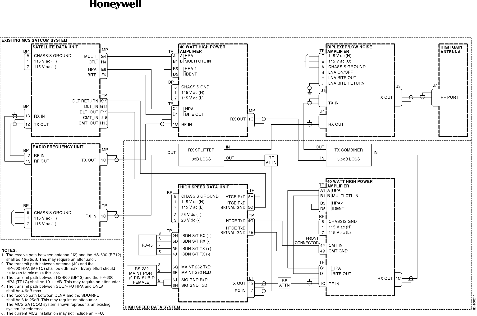
Figure 3-10. High Speed Data System Interconnect Diagram

INSTALLATION CHECK

SYSTEM DESCRIPTION AND INSTALLATION MANUAL
HS--600 High Speed Data System
23--20--31
30 May 2002
Use or disclosure of information on this page is subject to the restrictions in the proprietary notice of this document.
Page 4--1
SECTION 4
INSTALLATION CHECK
1. Overview
A. General
(1) The procedures that follow are designed to check for the satisfactory installation of
the HS--600 HSD system prior to LRU installation.
2. Installation Checkout
A. General
(1) The HSD system aircraft installation checkout should include, but is not limited to, the
following steps:
•Cable loss checks
•Power checks
•RF checks.
B. Cable Loss Checks
(1) HS--600 HSU to HPA Path Loss
(a) Measure the total cable and connector losses between the HSU TX output
(BP13) to the HPA RF input (TP1C).
(b) If necessary, install an attenuator to achieve a total loss of 19--21 dB.
(2) HPA to Antenna Loss
(a) Measure the total loss between the HS--600 HPA RF output (MP1C) to the
antenna RF port (J2).
(b) Enter this value into parameter No. 5 through the HS--600 maintenance port. Do
no change any other parameters. Do no forget to save the changes.
(c) Assuming that this value is equal to the SDU HPA to antenna loss, enter the
value through the SDU CMT using the keystrokes listed below. If the loss is more
than 1 dB different from the HS--600 HPA to antenna loss, measure the loss first
before entering the value.
(d) From the SDU main menu, make the following selections:
•F) Physical Layer Menu
•C) Power Control Menu
•D) Manual Power Control Menu
•B) HGA HPA to Antenna Loss.
(e) Enter the loss value. If greater than 5 dB, enter 5 dB.
SYSTEM DESCRIPTION AND INSTALLATION MANUAL
HS--600 High Speed Data System
23--20--31
30 May 2002
Use or disclosure of information on this page is subject to the restrictions in the proprietary notice of this document.
Page 4--2
C. Power Checks
(1) Check the pins listed in Table 4-1.
Table 4-1. Power Checks
LRU Connector Pin Signal
HS--600 HSU BP1 115 V ac (High)
BP7 115 V ac (Low)
BP2 28 V dc (High)
BP3 28 V dc (Low)
HSD System HPA (Note) BP1 115 V ac (High)
BP7 115 V ac (Low)
NOTE: The HPA is also available as 28V dc. See Honeywell Pub. No. C15--5111--005 for installation details.
D. RF Checks
(1) Check the pins listed in Table 4-2. Figure 4-1 shows the receive (RX) path loss and
Figure 4-2 shows the transmit (TX) path loss. These losses are achieved by a
combination of RF coaxial cable losses and installed RF attenuators (the latter, if
required).
Table 4-2. RF Checks
From LRU Connector Pin To LRU Connector Pin
RX Splitter RX IN DLNA J2 (RX OUT)
RX OUT MCS--3000 SDU or
MCS--4000 SDU or
MCS--7000 SDU
BP13 (RX IN)
RX OUT MCS--6000 RFU TP1C (RX IN)
RX OUT RF Attenuator IN
RF Attenuator OUT HS--600 HSU BP12 (RX IN)
Combiner TX OUT DLNA J1 (TX IN)
TX IN HSD System HPA MP1C (RX OUT)
TX IN SATCOM System HPA MP1C (RX OUT)
HS--600 HSU BP13 (TX OUT) RF Attenuator IN
RF Attenuator OUT HSD System HPA TP1C (RF IN)
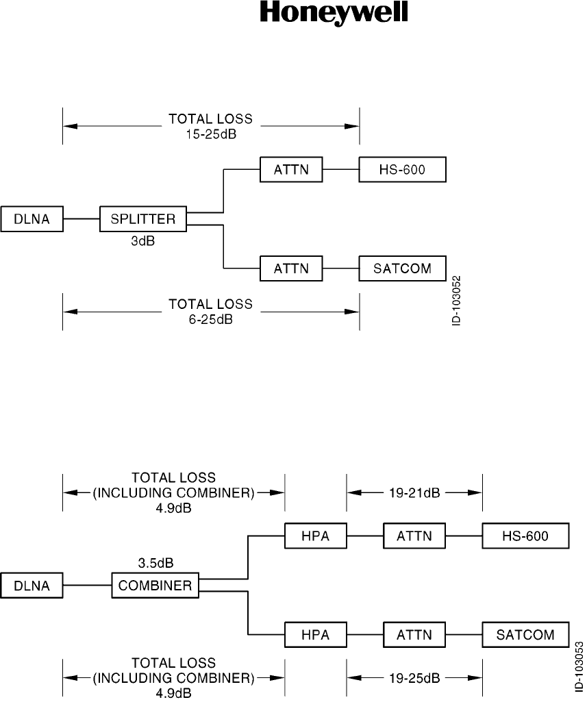
SYSTEM DESCRIPTION AND INSTALLATION MANUAL
HS--600 High Speed Data System
23--20--31
30 May 2002
Use or disclosure of information on this page is subject to the restrictions in the proprietary notice of this document.
Page 4--3
Figure 4-1. RX Path Loss
Figure 4-2. TX Path Loss

SYSTEM DESCRIPTION AND INSTALLATION MANUAL
HS--600 High Speed Data System
23--20--31
30 May 2002
Use or disclosure of information on this page is subject to the restrictions in the proprietary notice of this document.
Page 4--4
Blank Page

ADJUSTMENT/TEST

SYSTEM DESCRIPTION AND INSTALLATION MANUAL
HS--600 High Speed Data System
23--20--31
30 May 2002
Use or disclosure of information on this page is subject to the restrictions in the proprietary notice of this document.
Page 5--1
SECTION 5
ADJUSTMENT/TEST
1. Overview
A. General
(1) This section provides instructions for adjusting/testing the HS--600 HSD system.
2. Details
A. General
(1) Access to the maintenance functions is obtained by connecting a personal computer
(PC) to the RS--232 maintenance port connector. The maintenance port connector is
a 9--pin sub--D connector that is connected to the HSU mounting tray connector.
(2) To operate with a PC, the initial settings of the maintenance port must be as follows:
•Speed, normally 115,200 bps
•8 data bits
•No parity
•1stopbit
•Turn caps lock ON.
B. Software
(1) The software can be any communications package that can send and receive ASCII
at 115,200 baud rate, 8 bits with no parity bit, and 1 stop bit. Among the programs
that have been used are ProComm and HyperTerminal from Windows.
C. System Initialization
(1) Apply power to the SATCOM and HS--600 systems.
(2) Connect a cable from the PC to the front of the SDU as given in Table 5-1. The cable
connector that attaches to the front of the SDU is a 53--pin male connector. The cable
connector that attaches to the PC is a 9--pin female sub--D connector. Refer to
Figure 5-1.
Table 5-1. SDU to PC Wire List
From SDU Front Connector Pin To PC Connector Pin
42 3
43 2
49 5
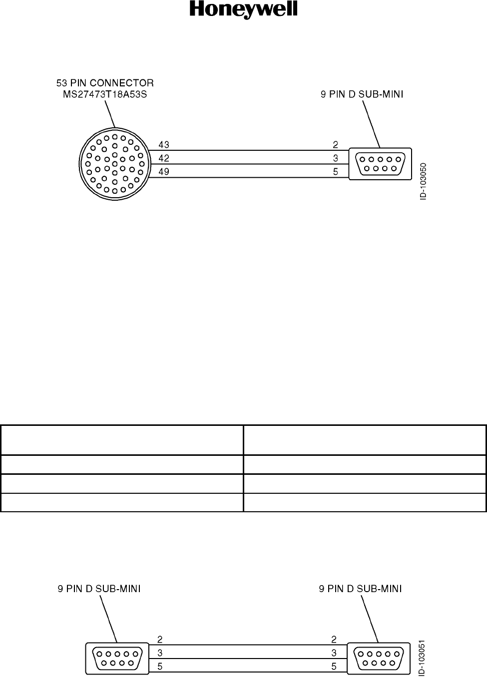
SYSTEM DESCRIPTION AND INSTALLATION MANUAL
HS--600 High Speed Data System
23--20--31
30 May 2002
Use or disclosure of information on this page is subject to the restrictions in the proprietary notice of this document.
Page 5--2
Figure 5-1. SDU to PC Cable
(3) Connect the PC using HyperTerminal, ProComm, or equivalent.
(4) Set the terminal settings to: Direct Connect to Comm 1, 9600 N 81.
(5) Press ENTER to see the SDU main menu.
NOTE: Refer to paragraph 1.A.(5) in section 1 for the periodic data word setup.
(6) Align the inertial reference system (IRS).
(7) Remove the cable from the SDU to the PC.
(8) Connect a cable from the HSU to the RS--232 maintenance port as given in
Table 5-2.
Table 5-2. HSU to RS--232 Maintenance Port Wire List
From HSU Connector Pin
To RS--232 Maintenance Port 9--Pin Female
D--Type Connector Pin
TP6G 3
TP6F 2
TP6J, TP6H 5
(9) Connect a cable from the RS--232 maintenance port to the PC as shown in
Figure 5-2. The cable connector that attaches to the HSU RS--232 maintenance port
is a 9--pin male sub--D connector. The cable connector that attaches to the PC is a
9--pin female sub--D connector.
Figure 5-2. HSU RS--232 Maintenance Cable

SYSTEM DESCRIPTION AND INSTALLATION MANUAL
HS--600 High Speed Data System
23--20--31
30 May 2002
Use or disclosure of information on this page is subject to the restrictions in the proprietary notice of this document.
Page 5--3
(10) Set up the terminal according to paragraph 2.A.(2) of this section.
(11) Once the SATCOM system is logged on, then the HS--600 system will log on.
(12) View the maintenance port information for a typical start--up. Refer to paragraph 2.D.
of this section.
(13) Once WAIT FOR CALL is indicated, the system is ready for use.
D. Typical Maintenance Port Start--Up Information
(1) The information given in Table 5-3 is the typical output from the HS--600 maintenance
port following a power cycle. The information assumes that the IRS has aligned and
the multi--channel SATCOM has logged on.
Table 5-3. Typical HS--600 Maintenance Port Information
************** M4--IDUBOOTHEADER ************
(1.) Download IDU Flash
(2.) Boot from Flash (default), wait...
Please input your choice: .......................................................................
...............................................................................................
...............................................................................................
...............................................................................................
...............................................................................................
...............................................................................................
..............................................................
Time Out Booting from Flash Now, please wait...
00.250:MNS--NS |MNS_CONFIG_RQ |ff:ff: 0#270: 00 00 00 01 00 01 08 02 08 08
00.270:NS--MNS |MNS_CONFIG_CO |ff:ff: 0#270: 02 02 53 01 00 01 08 02 08 08
00.280:SM --CC |SM_CONFIG_RQ |ff:ff:ff#264: 00 00 00 01 00 41 61 10 00 80
00.290:CC --SM |SM_CONFIG_CO |ff:ff:ff#264:Config CC OK 02 00 43 01 00 41
00.290:SM --APP|SM_CONFIG_RQ |ff:ff:ff#0:

SYSTEM DESCRIPTION AND INSTALLATION MANUAL
HS--600 High Speed Data System
23--20--31
30 May 2002
Use or disclosure of information on this page is subject to the restrictions in the proprietary notice of this document.
Page 5--4
Table 5-3. Typical HS--600 Maintenance Port Information (cont)
Glocom Multi Channel M4 Terminal IDU software start up...
IDU SW Version: A1.00 04/05/2002
Initializing channel 0...
copy bulletin board from flash memory ok, issue no is 23
Initializing channel 1...
copy bulletin board from flash memory ok, issue no is 23
!!!!!!!!!!!!!!!!!!!!!!!!!!!!!!!!!!!!!!!!!!!!!!!!!!!
Waiting for LOG ON message from HTCE!!!
!!!!!!!!!!!!!!!!!!!!!!!!!!!!!!!!!!!!!!!!!!!!!!!!!!!
Power Control: PH(0) = 15.0
EIRP(0) = 25.0
PM(0) = 9.5
GH(0) = 58.0
Obo(0) = 2.0
Set Economy Flag = 0
IIIIIIIIIIIIIIIIIIIIIIIIIIIIIIIIIIIIIIIIIIIIIIIIIIIIIIIIIIIIIIIIIIIIIIIIIIIIIIIIIIIIII¯
§§
§ Press [ENTER] to start Maintenance Setting §
§§
EIIIIIIIIIIIIIIIIIIIIIIIIIIIIIIIIIIIIIIIIIIIIIIIIIIIIIIIIIIIIIIIIIIIIIIIIIIIIIIIIIIIII
00.900:APP--SM |SM_CONFIG_CO |ff:ff:ff#0:Config APP OK
( 20), ISDN module buffer allocated= 1
( 40), ISDN module buffer allocated= 1
* Have found “Format B”
( 60), ISDN module buffer allocated= 1
( 80), ISDN module buffer allocated= 1
( 100), ISDN module buffer allocated= 1
* Have found “Format B”
( 120), ISDN module buffer allocated= 1
( 140), ISDN module buffer allocated= 1

SYSTEM DESCRIPTION AND INSTALLATION MANUAL
HS--600 High Speed Data System
23--20--31
30 May 2002
Use or disclosure of information on this page is subject to the restrictions in the proprietary notice of this document.
Page 5--5
Table 5-3. Typical HS--600 Maintenance Port Information (cont)
* Waiting for MSG_LOGON_ACK from ACSE.
CHNL 0(T=14109) changed to OC--Reg 2
* Current state is LOG_ON.
CHNL 0(T=14111) , got sync response from ODU,now request DSP setting...
CHNL 0(T=14112) , got DSP settings , now load FPGA program...
Oscillate correction= --125 (i.e. FFFFFF83)!
CHNL 0 Set Tx channel to 2AB4.
CHNL 0(T=14228) ,DSP load FPGA ok,now load TDM code...
CHNL 0(T=14228) ,STATE CHANGE FROM 0 ------>1
CHNL 0(T=14233) ,TDM Rx stopped!
CHNL 0 Set Tx channel to 2AB4.
CHNL 0 : Rx is 2ab4
CHNL 0(T=14233) ,STATE CHANGE FROM 1 ------>2
CHNL 0(T=14233) ,DSP load TDM ok,now tune to NCSC...
CHNL 0(T=14300) ,Got frame synchronization ...
CHNL 0(T=14300) ,Bulletin Board Update Ok...Issue No 23
CHNL 0(T=14300) ,STATE CHANGE FROM 2 ------>3
CHNL 0(T=14300) ,BB Update Ok,wait for SBS finishing...
CHNL 0(T=14300) ,Init/ReInit SBS!!
CHNL 0(T=14300) ,SBS started!!
Position: Lat=33.000000, Long=--112.003326
CHNL 0 SBS ID = 6
CHNL 0(T=14303) ,SBS finished!!
CHNL 0 : Rx is 24cc
CHNL 0(T=14304) ,STATE CHANGE FROM 3 ------>6
CHNL 0(T=14304) ,Start ocean region registration...
CHNL 0(T=14306) ,get sync on NCRA channel, continue ORR...
Chl 0 wait timer TM081 for 2630
CHNL 0(T=14569) ,TM081 timer out !
CHNL 0 MESRR Tx: 249C
CHNL 0 burst backoff 16 dBm
CHNL 0 PwrCtrl cmd: 29 00 A0 00 00
CHNL 0 Set Tx channel to 249C.
CHNL 0 Tell DSP Tx idle channel is 2AB4.
CHNL 0(T=14569) ,send orr burst
CHNL 0 : Rx is 2ab4
CHNL 0(T=14780) ,STATE CHANGE FROM 6 ------>4
CHNL 0(T=14780) ,Mes is in idle ,wait for call...
CHNL 0(T=14780) ,TDM Rx stopped!
CHNL 0 Set Tx channel to 2AB4.
CHNL 0 : Rx is 2ab4
CHNL 0(T=14780) ,STATE CHANGE FROM 4 ------>2
CHNL 0(T=14827) ,Got frame synchronization ...
CHNL 0(T=14827) ,Wait for call...
CHNL 0(T=14827) ,STATE CHANGE FROM 2 ------>4
( 160), ISDN module buffer allocated= 1
( 180), ISDN module buffer allocated= 1
* Have found “Format B”

SYSTEM DESCRIPTION AND INSTALLATION MANUAL
HS--600 High Speed Data System
23--20--31
30 May 2002
Use or disclosure of information on this page is subject to the restrictions in the proprietary notice of this document.
Page 5--6
E. Maintenance Menu Items
(1) The maintenance menu items given in Table 5-4 can be accessed through the
maintenance port by pressing the ENTER key after the HS--600 system has booted
up. (See paragraph 2.D. in this section.)
NOTE: ItemslistedinTable5-4areforreferenceonlyandwillbesetbythe
manufacturer.
NOTE: Changes to the parameters listed in Table 5-4 should only be accomplished
by qualified personnel or after consulting your Honeywell representative.
Table 5-4. Maintenance Menu Items
IIIIIIIIIIIIIIII Maintenance Parameters Setting IIIIIIIIIIIIIIIIIIIIIIIIIIIIIIIII¯
§§
§ 1. P(tx) Initial EIRP: 25.0dBW §
§ 2. Ref. oscillator correction factor: --125Hz §
§ 3. Transmit Doppler compensation adjustment rate: 60Hz/sec §
§ 4. G(M--H) ISE MTU--to--HPA output gain: 40dB §
§ 5. HPA output to antenna input loss: 2dB §
§ 6. G(Amin) Minimum usable reported antenna gain: 7dB §
§ 7. P(omin) Max. allowed HPA average output power: 17.0dBW §
§ 8. Enabled BEARE Service Interface: 0 §
§ 9. Min. Frame No. for TX port: 3 §
§ A. HPA Format Selection: N §
§ S. Save setting and Exit §
§§
EIIIIIIIIIIIIIIIIIIIIIIIIIIIIIIIIIIIIIIIIIIIIIIIIIIIIIIIIIIIIIIIIIIIIIIIIIIIIIIIIIIIIIIIIIIIIIIIIIIIII
Enter your selection: 1
P(tx) Initial EIRP, range 20 to 25dBW in 0.5dBW steps: 25.0Hz
Please enter new value between 20.0 to 25.0):
Keep current value!
Enter your selection: 2
Reference oscillator correction factor
range +/--2200Hz, in 1Hz step: --125Hz
Please enter new value between --2200 to 2200(+/--XXXX):
Keep current value!
Enter your selection: 3
Transmit Doppler compensation adjustment rate, default is 60Hz/sec.
Please make your choice :
1. 30Hz/sec.
2. 60Hz/sec.
Enter your choice:
Use default Transmit Doppler compensation adjustment rate, 60Hz/sec.

SYSTEM DESCRIPTION AND INSTALLATION MANUAL
HS--600 High Speed Data System
23--20--31
30 May 2002
Use or disclosure of information on this page is subject to the restrictions in the proprietary notice of this document.
Page 5--7
Table 5-4. Maintenance Menu Items (cont)
Enter your selection: 4
ISE MUT--TO--HPA output gain
range 36 to 42 dB, in 1 dB steps: 40Hz
Please enter new value between 36 to 42:
Keep current value!
Enter your selection: 5
HPA output to antenna input loss,
range 1--6 dB, in 1dB steps: 2Hz
Please enter new value between 1 to 6:
Keep current value!
Enter your selection: 6
Minimum usable reported antenna gain below which the ISE
ceases operation of the HSD channel
range 7 to 12 dB, in 1dB steps: 7Hz
Please enter new value between 7 to 12:
Keep current value!
Enter your selection: 7
Maximum allowed HPA average output power,
range 20 to 60W, or 13 to 18 dBW, in 0.5dB steps: 17.0Hz
Please enter new value between 13.0 to 18.0):
Keep current value!
Enter your selection: 8
Enabled Bearer Service Interface, 0 for ISDN S/T and 1 for PCM: 0Hz
Please enter new value between 0 to 1:
Keep current value!
Enter your selection: 9
Min. frame number for ack TX port: 3Hz
Please enter new value between 2 to 12:
Keep current value!
Enter your selection: A (NOTE: Must be Upper Case)
“A” or “B” for different HPA types: N
Please enter your new character (A--B):
Keep current value!

SYSTEM DESCRIPTION AND INSTALLATION MANUAL
HS--600 High Speed Data System
23--20--31
30 May 2002
Use or disclosure of information on this page is subject to the restrictions in the proprietary notice of this document.
Page 5--8
Table 5-4. Maintenance Menu Items (cont)
Enter your selection: S (NOTE: Must be Upper Case)
Maintenance Parameters have been saved.
The new maintenance parameters will be used by system.
Please wait for system setup...
NOTE: Must power cycle HS--600 for parameter save to take effect.
****************MainMenu*******************
1.Protocol Mode
2.Manual Mode
3.Change Password
Enter your selection: 1
NOTE: Press <ESC><ESC> or power cycle to exit from this menu.
******************Menuinprotocolmode**************************
1.Event Log
ESC. Exit
Enter your selection:
******************Menuinprotocolmode**************************
1.Event Log
ESC. Exit
Enter your selection: 1
***************** Event Log Menu *********************
1.Display last 20 Event Log records
2.Display specified range of Event Log records
3.Display all Event Log records
V.Verify a specified Event Log Record in Hex format
C.Clear all Event Log records
ESC. Exit
Enter your selection:
******************Menuinprotocolmode**************************
1.Event Log
ESC. Exit
Enter your selection:

FAULT ISOLATION

SYSTEM DESCRIPTION AND INSTALLATION MANUAL
HS--600 High Speed Data System
23--20--31
30 May 2002
Use or disclosure of information on this page is subject to the restrictions in the proprietary notice of this document.
Page 6--1
SECTION 6
FAULT ISOLATION
1. Overview
A. General
(1) To be supplied.

SYSTEM DESCRIPTION AND INSTALLATION MANUAL
HS--600 High Speed Data System
23--20--31
30 May 2002
Use or disclosure of information on this page is subject to the restrictions in the proprietary notice of this document.
Page 6--2
Blank Page

MAINTENANCE
PRACTICES

SYSTEM DESCRIPTION AND INSTALLATION MANUAL
HS--600 High Speed Data System
23--20--31
30 May 2002
Use or disclosure of information on this page is subject to the restrictions in the proprietary notice of this document.
Page 7--1
SECTION 7
MAINTENANCE PRACTICES
1. Overview
A. General
(1) This section provides instructions for removing, reinstalling, and adjusting the
HS--600 HSU, combiner, and/or splitter that has been previously installed by the
aircraft manufacturer or completion center. Adjustment information is called out as
required.
CAUTION: SHOULD ANY INSTALLATION CRITICAL CASES ARISE WITH THE
REINSTALLATION OF ANY UNIT, YOU MUST COMPLY 100 PERCENT
WITH THE INSTRUCTION.
CAUTION: TO PREVENT DAMAGE TO EQUIPMENT, TURN AIRCRAFT POWER OFF
WHEN REMOVING OR INSTALLING LRUS.
B. Equipment and Materials
(1) No additional special equipment or materials, other than those commonly used in the
shop, are required to install the units in existing trays and clamps, and adjust the
system. Do not over tighten mounting screws. Where torque values are not given, it
is acceptable to finger tighten the mounting screws.
2. Procedure for the HS--600 HSU
A. Removal and Reinstallation Procedures
(1) Remove the HSU.
(a) Remove power from the HSU and the interfacing subsystems (such as SATCOM.
Circuit breakers for the systems are typically located on the flight deck.
(b) Loosen the mounting tray holddown clamps by rotating in a counterclockwise
direction.
(c) Slowly pull forward on the unit handle to separate the unit and tray connectors
and slide the unit out of the tray, lifting slightly to clear the holddown clamps.
(d) Place electrostatic protective covers on the HSU rear connector to protect the
pins from damage.
(e) Place the HSU in a protective static--resistant bag and protective carrying case.

SYSTEM DESCRIPTION AND INSTALLATION MANUAL
HS--600 High Speed Data System
23--20--31
30 May 2002
Use or disclosure of information on this page is subject to the restrictions in the proprietary notice of this document.
Page 7--2
(2) Reinstall the HSU.
(a) Remove the HSU from the protective carrying case and protective
static--resistant bag.
(b) Remove the electrostatic protective covers from the HSU rear connector.
(c) Slide the unit into the mounting tray.
CAUTION: WHEN PLACING THE UNIT ON THE MOUNTING TRAY, DO NOT
FORCE FIT. IF MATING IS DIFFICULT, REMOVE THE UNIT AND
CHECK FOR CONNECTOR PINS THAT CAN BE BENT OR OUT OF
ALIGNMENT. ALSO VISUALLY CHECK THE ALIGNMENT OF THE
RECEPTACLE ON THE MOUNTING TRAY.
(d) Gently slide the unit backwards until its connectors are fully engaged with the
mating connectors of the mounting tray.
(e) Put the holddown clamps in place and tighten the knobs in a clockwise direction
until the proper torque is applied (clutch engages).
(f) Reapply power to the HSU and its interfacing equipment.
NOTE: Upon applying primary power, the HSU will automatically power up and
start a POST.
B. Adjustment Procedures
(1) Not applicable.
C. Repair Procedures
(1) Not applicable.
D. Return to Service Procedures
(1) Refer to test procedures in the INSTALLATION CHECK section of this manual.
3. Procedure for the Combiner/Splitter
A. Removal and Reinstallation Procedures
(1) Remove the combiner.
(a) Remove power from the HSU. Circuit breakers for the HSU are typically located
on the flight deck.
(b) Locate the combiner.
(c) Disconnect the aircraft connectors from the combiner and place protective covers
on the connectors.
(d) Remove the six screws holding the combiner in position.

SYSTEM DESCRIPTION AND INSTALLATION MANUAL
HS--600 High Speed Data System
23--20--31
30 May 2002
Use or disclosure of information on this page is subject to the restrictions in the proprietary notice of this document.
Page 7--3
(2) Reinstall the combiner.
(a) Attach the combiner using six screws.
(b) Remove the protective covers from the connectors and install the aircraft
connectors on the combiner.
(c) Reapply power to the HSU and its interfacing equipment.
(3) Remove the splitter.
(a) Remove power from the HSU. Circuit breakers for the HSU are typically located
on the flight deck.
(b) Locate the splitter.
(c) Disconnect the aircraft connectors from the splitter and place protective covers
on the connectors.
(d) Remove the two screws holding the splitter in position.
(4) Reinstall the splitter.
(a) Attach the splitter using two screws.
(b) Remove the protective covers from the connectors and install the aircraft
connectors on the splitter.
(c) Reapply power to the HSU and its interfacing equipment.
B. Adjustment Procedures
(1) Not applicable.
C. Repair Procedures
(1) Not applicable.
D. Return to Service Procedures
(1) Refer to test procedures in the INSTALLATION CHECK section of this manual.

SYSTEM DESCRIPTION AND INSTALLATION MANUAL
HS--600 High Speed Data System
23--20--31
30 May 2002
Use or disclosure of information on this page is subject to the restrictions in the proprietary notice of this document.
Page 7--4
4. Instructions for Continued Airworthiness, Code of Federal Regulation
CFR 91.213
A. General
(1) Maintenance requirements and instructions for continued airworthiness of the
HS--600 HSU components are contained in the following paragraphs:
(2) Installation of the HSU on an aircraft by Supplemental Type Certificate or Form 337
obligates the aircraft operator to include the maintenance information provided by this
manual in the operator’s Aircraft Maintenance Manual and the operator’s Aircraft
Scheduled Maintenance Program.
B. Instructions
(1) Maintenance information for the HSU (system description, removal, installation,
testing, etc.) is contained in this manual.
(2) LRU part numbers and other necessary part numbers contained in this manual
should be placed into the aircraft operator’s appropriate aircraft Illustrated Parts
Catalog (IPC).
(3) Wiring diagram information contained in this manual should be placed into the aircraft
operator’s appropriate aircraft Wiring Diagram Manuals.
(4) The high speed data system components are considered on--condition units and no
additional maintenance is required other than a check for security and operation at
normal inspection intervals.
(5) If a system component is inoperative, remove unit, secure cables and wiring, collar
applicable switches and circuit breakers, and placard them inoperative. Revise
equipment list and weight and balance as applicable prior to flight and make a log
book entry that unit was removed. Refer to section 91.213 of the CFR or the aircraft’s
minimum equipment list (MEL).
(6) The HSU components can be repaired only at a factory authorized repair center or an
appropriately rated FAA Part 145 repair station.
(7) Once repaired, reinstall the LRU in the aircraft in accordance with the original Form
337 approved data or instructions in this manual. Do a return--to--service test of the
system and approve it for return to service with a log book entry required by section
43.9 of the FAR.
(8) Scheduled Maintenance Program tasks to be added to the aircraft operator’s
appropriate aircraft maintenance program are as follows:
(a) Recommended Periodic Scheduled Servicing Tasks: None Required
(b) Recommended Periodic Inspections: None Required
(c) Recommended Periodic Scheduled Preventative Maintenance Tests (Tests to
determine system condition and/or latent failures): None Required

APPENDIX A

SYSTEM DESCRIPTION AND INSTALLATION MANUAL
HS--600 High Speed Data System
23--20--31
30 May 2002
Use or disclosure of information on this page is subject to the restrictions in the proprietary notice of this document.
Page A--1
APPENDIX A
M4 CALL CAUSE CODE LIST
1. Overview
A. General
(1) The following list of cause codes in Table A--1 describes the various conditions of a
failed M4 terminal call.
Table A--1. Call Cause Code List
Cause Code Description Note
0001 Invalid LES code entry.
0003 Selected land earth station (LES) does not support M4 services.
0004 Invalid dialing sequence detected.
0005 Out of memory capacity.
0101 Cannot obtain the network coordination station assignment (NCSA) channel from the
Bulletin Board.
0102 Cannot obtain the land earth station assignment (LESA) channel from the Bulletin Board.
0103 Failed to stop the time division multiplex (TDM) receive command before tuning to the
NCSA/LESA channel.
0104 Failed to synchronize to the NCSA/LESA channel frequency.
0105 User cleared call before the single channel per circuit (SCPC) channel was assigned.
0106 Failed to receive the channel assignment.
0107 85H code (instead of channel assignment) received.
0108 DSP failed to reset after call clear.
0109 DSP failed to reset before loading the Mini M/high speed data (MM/HSD) service code.
0110 DSP failed to load the M1/M4 service code.
0111 Incorrect channel received from the channel assignment SU (86h).
0120 Erroneous frame number detected on 81H SU. Response SU (82H) not sent.
0121 Erroneous slot number detected on 81H. Response SU (82H) not sent.
0122 Failed to obtain the MESRP channel from the Bulletin Board.
0123 DSP did not report after response SU before it transmitted.
1001 Normal Clearing.
Mobile Earth Station (MES) is clearing the call as instructed by the relevant MES terminal
equipment (i.e., normal clearing due to MES terminal “on--hook” etc.).
1.
1011 MES Busy.
MES is rejecting the call because the specified MES terminal number is currently busy, and
MES has not been authorized to divert calls which are addressed to that number.
1.

SYSTEM DESCRIPTION AND INSTALLATION MANUAL
HS--600 High Speed Data System
23--20--31
30 May 2002
Use or disclosure of information on this page is subject to the restrictions in the proprietary notice of this document.
Page A--2
Table A--1. Call Cause Code List (cont)
Cause Code NoteDescription
1012 MES is clearing the fixed--originated call because subsequent to the acceptance of the call
and signaling of the identity of the mobile terminal to which the call will actually be routed,
that terminal has become busy and therefore cannot be rung.
1.
1021 Call Failed, MES Time--out, No Answer
MES is clearing the call because appropriate “off--hook” signaling has not been received
from the addressed MES terminal (including any authorized diversions) within the allowed
time limit.
1.
1081 Call Failed, MES Terminal # Not Installed
MES is rejecting the call because the specified MES terminal number has not been
installed, and MES has not been authorized to divert calls which are addressed to that
number.
1.
1091 Call Failed, MES Terminal # out of Service
MES is rejecting the call because the specified MES terminal number is currently out of
service, and MES has not been authorized to divert calls which are addressed to that
number.
1.
1092 MES is clearing the fixed--originated call because subsequent to the acceptance of the call
and the signaling of the identity of the mobile terminal to which the call will actually be
routed, that terminal has become out--of--service and therefore cannot be rung.
1.
1141 Call Cleared, pre--empted at MES
MES clear: pre--emption for higher priority call.
1.
1142 Call Refused due to Distress Call from MES
MES clear: (Fixed) MES has initiated a distress call.
1.
1143 Call Cleared, pre--empted at MES
Fixed--originated call cleared by MES due to SATCOM reporting that it is no longer logged
on.
1.
1144 Attempted Call pre--empted by MES Distress
MES clear: (mobile) MES has initiated a distress call.
1.
1145 Call Cleared, pre--empted by MES
Mobile--originated call cleared by MES due to SATCOM reporting that it is no longer logged
on.
1.
1146 Attempted Call Abandoned by MES Terminal
MES is prematurely clearing the mobile--originated call which is in the process of being
established because the MES user has abandoned the call (by placing, the originating
terminal “on--hook).
1.
11A0 LES is clearing the call because the credit card being used is not valid (at this LES) for calls
to the country indicated in the “Service Address’ information received from the MES.
1.
11D1 Call Failed, Request Data Invalid
LES is rejecting the call because the “Service Nature” and/or “Service Type” and/or
“Channel parameter” information received from the MES is invalid (e.g., not currently
defined in the SDM, mutually contradictory, or not applicable to a MES--originated call.)
1.

SYSTEM DESCRIPTION AND INSTALLATION MANUAL
HS--600 High Speed Data System
23--20--31
30 May 2002
Use or disclosure of information on this page is subject to the restrictions in the proprietary notice of this document.
Page A--3
Table A--1. Call Cause Code List (cont)
Cause Code NoteDescription
11D2 Call Failed, Insufficient Digits in Service Address
LES is clearing the call because the “Service Address” information received from the MES is
invalid (e.g., less than 2 digits). If the customer is dialing a valid phone number or prefix
code, verify that the MES has a corresponding Inmarsat mobile number (IMN)s in the LES
access control and signalling equipment (ACSE) database.
1.
11D3 Call Failed, Invalid Service Address
LES is clearing the call because the “Service Address” information received from the MES is
a 2--digit address which is either undefined or which is currently unavailable at this LES.
1.
11D4 LES is clearing the call because the “credit card data” information received from the MES is
invalid. (This does not imply that the credit card itself is invalid.)
1.
11D5 LES is clearing the call because the “Service Address” information received from the MES
contains a country code which is regarded (by this LES) as invalid.
1.
11D6 LES is clearing the call because the “PID” information received from the MES in the
“scrambling vector” message (type 8D) is not consistent with the personal identification
number (PID) information in the fixed/MES--originated (PID) and PID/MES Registration
Tables at the LES as it relates to this call.
1.
11D7 LES is failing the call because the service requested by the MES in the distress, urgency or
safety access request is not 4.8 kbps AMBE telephony.
1.
11D8 LES is clearing the call because the service address received from the MES requesting
distress, urgency or safety priority is not a two or three--digit code.
1.
11E0 LES is clearing the call because the credit card PIN received from the MES is not
considered (at this LES) to be valid.
1.
11E1 LES is clearing the call because it has been determined that an excessive number of
consecutive call attempts with invalid credit card have been made.
1.
1201 MES ack: received a simplex call. 1.
1202 (Spot Beam Handover): MES is ready to make the transition from the current beam to the
next beam.
1.
1261 MES ack: received a simplex call (unstable). 1.
1262 Call Cleared, MES Timeout Distress Test
MES clear: distress test call has not been cleared in 120s.
1.
1281 Call Failed, MES Cannot Accept
MES is rejecting the call because the MES is not equipped to provide the specified service.
1.
1291 Call Failed, MES Cannot Accept at Present
MES is rejecting the call because although it is equipped to provide the specified service, it
is not currently able to do so.
1.
12B1 Call Cleared by MES for Unspecified Reason
MES is rejecting or clearing the call for a reason which is not covered by any of the currently
defined “Cause” events.
1.

SYSTEM DESCRIPTION AND INSTALLATION MANUAL
HS--600 High Speed Data System
23--20--31
30 May 2002
Use or disclosure of information on this page is subject to the restrictions in the proprietary notice of this document.
Page A--4
Table A--1. Call Cause Code List (cont)
Cause Code NoteDescription
12C1 Call Faded, No Scrambling Vector Ack
MES clear: Scrambling Vector Ack (95) not received by the MES.
1.
12C2 MES is clearing the call because a “Credit Card Valid” message (type A7) has not been
received by the MES within the allowed time limit.
1.
12C3 Call Failed, MES Timeout, No Terrestrial Answer
MES is clearing the call because an “LES Connect” message (type 8C) has not been
received by the MES within the allowed time limit.
1.
12C4 MES is clearing the call because the “authentication query” ISU message (type B4) and/or the
“authentication query” SSU message (type B5) have not been received by the MES within the
allowed time limit.
1., 2.,
13., 14.,
15.
12C5 MES is clearing the call because an expected supplementary services SU(s) has (have) not
been received by the MES within the allowed time limit.
1.
12C6 MES is clearing the call because the “supplementary services interrogation” ISU (type B2H),
and/or ”subscriber digits” SSU (type AD H) messages have not been received by the MES
within the allowed time limit.
1.
12C7 MES is clearing the call because a “SCPC channel release” SU (type 8AH) has not been
received by the MES, in response to the transmission of a “notification acknowledge”
message (type BAH) during the supplementary services call diversion information retrieval
process, within the allowed time limit.
1.
12C8 (Spot Beam Handover): MES is clearing the call session in the next beam because the MES
did not detect the LESH carrier on the new frequency.
1.
12D1 Call Failed, Spot Beam Data Invalid
LES is rejecting the call because the “spot beam ID” information received from the MES is
invalid, i.e., ID is not allocated on the satellite in use.
1.
12D2 Call Failed, Invalid Scrambling Vector (LES is clearing the call because the “Scrambling
Vector” information received from the the MES is invalid; i.e., 0000 H, 6959 H or 7 FFF H).
1.
1351 MES is clearing the call because the MES currently has insufficient free memory in which to
store the short message.
1.
1361 Call Cleared by MES; Cable Unwrap
MES is clearing the call because the above--decks equipment is about to “cable unwrap”.
1.
1362 Call Cleared, Long Interruption Reception
MES is clearing the call because a long--term interruption (16 sec) in reception of LES
carrier has occurred. The definition of a “long--term interruption” depends upon the service
type.
1., 3.
1363 Call Cleared, MES Antenna Repointed
(WS clear: switching ocean regions)
A secondary functional center of Multi--channel MES is clearing the call because the
primary functional center has commanded the above--decks equipment to repoint to a
different ocean region.
1.

SYSTEM DESCRIPTION AND INSTALLATION MANUAL
HS--600 High Speed Data System
23--20--31
30 May 2002
Use or disclosure of information on this page is subject to the restrictions in the proprietary notice of this document.
Page A--5
Table A--1. Call Cause Code List (cont)
Cause Code NoteDescription
1391 Aero Class MES only: MES is clearing the call because the call has lasted more than 700
km in linear travelled distance.
1.
1392 Aeronautical Class MES only: MES is clearing the call because it has moved out of spot
beam coverage.
1.
1393 Aeronautical Class MES only: MES in “cooperative mode” is clearing the call because of a
preemption request from the master entity. Call cleared by MES due to reported antenna
gain falling below the antenna gain threshold setting (Maintenance parameter #6) for more
than 10 seconds.
1.
1393 Call cleared by the MES due to the reported antenna gain falling below the antenna gain
threshold setting (maintenance parameter #6).
1.
1451 Call Failed, Terrestrial Circuits Congested
LES is rejecting the call because an appropriate terrestrial circuit is not currently available at
this specific LES.
1.
1452 Call Failed, LES Congested
LES is rejecting the call because an appropriate channel unit and associated terrestrial
circuit are currently not available at this LES.
1.
1502 (Spot Beam Handover): LES is ready to make the transition from the current beam to the
next beam and is clearing the call session in the current beam (normal clear).
1.
1541 Call Cleared, pre--empted at LES. (LES clear: pre--empted by higher priority call.) 1.
1551 Call Failed, LES Congested, No Channel
LES is rejecting the call because an appropriate satellite channel is not currently available at
this specific LES.
1.
1552 LES reject: appropriate time division multiplex (TDM)/time division multiple access (TDMA)
time slot not available.
1.
1581 Call Failed, Service Not Provided at this LES
LES is rejecting the call because the requested service is not provided by this specific LES.
1.
1591 LES is rejecting the call because the requested service is temporarily not available at this
specific LES.
1.
1592 LES is clearing the call because the specified credit card type is not currently supported by
this specific LES.
1.
15A1 LES is rejecting the call because the specified MES is not authorized for any service
(except Distress) at this specific LES. For a COMSAT LES, the phone is technically barred.
For other LESs, the phone is either financially or technically barred.
If the customer’s ISP or AA are authorized through this LES, verify that the MES ID has
corresponding IMNs in the LES ACSE database.
If the call setup proceeds to the point where the ACSE passes the call to the switch, check
to see 1) if the area code is invalid, 2) if a valid area code is missing in the switch, 3)check
to see if the ACSE passes the correct ICD message including the IMN (not all 9’s) to the
switch.
1., 4.
15A2 LES is rejecting the call because the specified MES is not authorized to use specific
requested service via this specific LES.
1.

SYSTEM DESCRIPTION AND INSTALLATION MANUAL
HS--600 High Speed Data System
23--20--31
30 May 2002
Use or disclosure of information on this page is subject to the restrictions in the proprietary notice of this document.
Page A--6
Table A--1. Call Cause Code List (cont)
Cause Code NoteDescription
15A3 LES is clearing the call because the “credit card data” information received from the MES
has been rejected by the credit card authorization process.
1.
15A4 LES is clearing the call because the data received from the MES in the “Authentication
Reply” message (type B6) has been declared “invalid” by the LES authentication process.
1., 5.
15A5 LES is rejecting the call because the specified PID is not authorized for any service at this
specific LES.
1.
15A6 LES is rejecting the call because the specified PID is not authorized to use specific
requested service via this specific LES. (User not authorized/barred for service in the LES
database.)
1.
15A7 LES is clearing the call because the service address received from the MES is not
authorized for the requested priority.
1.
15B1 Call Cleared by LES for Unspecified Reasons
LES is rejecting or clearing the call for a reason which is not covered by any of the currently
defined “Cause” events.
1.
15C1 Call Failed, LES Timeout, No Assignment
LES is rejecting the call because an appropriate “Channel Assignment” message has not
been received from the NCS by the LES within the allowed time limit.
1.
15C2 LES is clearing the call because the “Service Address” information has not been received
by the LES from MES within the allowed time limit.
1.
15C3 Call Failed, LES Timeout, No Scrambling Vector
LES is clearing the call because a “Scrambling Vector” message (type 8D) has not been
received by the LES from the MES within the allowed time limit.
1.
15C4 Call Failed, No Service Address or Vector
LES is clearing the call because neither the “Service Address” information nor a
“Scrambling Vector” message (type 8D) has been received by the LES from the MES within
the allowed time limit.
1.
15C5 LES is clearing the call because the complete “credit card data” information has not been
received by the LES within the allowed time limit.
1.
15C6 Call Failed, LES Timeout, No Return Carrier ID
LES is clearing the call because the Return Carrier Identifier (8B) was not received.
1.
15C7 LES is clearing the call because an “MES Connect” message (type 99) has not been
received by the LES within the allowed time limit.
1.
15C8 LES clear: SES Answer back not received. 1.
15C9 LES is clearing the call because an “Authentication Reply” message (type B6) has not been
received by the LES within the allowed frame limit.
1., 6.
15CA LES is clearing the call because a “notification acknowledge” message (type BAH) has not
been received by the LES within the allowed time limit.
1.
15CB LES is clearing the call because the request sequence number contained in the received
“notification acknowledge”message (type BA) is not valid (i.e. eithernot ‘0’ or not the next value
in the sequence).
1.

SYSTEM DESCRIPTION AND INSTALLATION MANUAL
HS--600 High Speed Data System
23--20--31
30 May 2002
Use or disclosure of information on this page is subject to the restrictions in the proprietary notice of this document.
Page A--7
Table A--1. Call Cause Code List (cont)
Cause Code NoteDescription
15CC Aeronautical Class MES only: (Spot Beam Handover): LES is terminating the procedure
because it did not receive a response to the Handover Request from the NCS.
1.
15CD (Spot Beam Handover): LES is clearing the call session in the next beam because the MES
did not indicate that it was ready to make the transition (possibly because the MES did not
receive the Channel Assignment).
1.
15D1 LES is rejecting the call because the “Channel Assignment” message received from the
NCS contains inappropriate or conflicting information.
1.
15D2 LES is clearing this MES ID and channel number in the busy lists at LES and NCS because
a new call to/from this MES is being set--up (and thus any previous call to/from this MES
cleared).
1.
15E1 Call Cleared, MES still Transmitting Fault
LES is attempting to clear an MES which has sent an SCPC channel release message but
is found still to be transmitting 5.12 sec later.
1.
1651 Call Failed, LES Congested, No Channel Unit
LES is rejecting the call because an appropriate channel unit is not currently available at
this specific LES.
1.
1661 Call Failed, Long Interruption in Reception
LES is clearing the call because of an interruption in reception of the MES carrier exceeding
the allowed time limit of 62 seconds.
1.
16C1 LES clear: SEST carrier not received. 1.
16C2 LES is clearing the call because an appropriate SCPC MES carrier has not been received
by the LES (at the commencement of the call) within the allowed time limit.
1.
16C3 (Spot Beam Handover): LES is clearing the call session in the next beam because the LES did
not detect the MESH carrier on the new frequency
1.
1790 LES is clearing the call because of a malfunction in the credit card validity checking
database or in the communications links.
1.
1791 LES is clearing the call because of a malfunction in the authentication checking database or
in the communication links.
1.
1811 NCS is rejecting the call because the specified MES ID is in the “S busy” list at the NCS. 1.
1812 NCS is rejecting the call because the specified MES is busy with an IPDS call at the NCS. 1.
1841 NCS is pre--empting the call in order to free the MES for an incoming call with priority 1. 1.
1842 NCS is pre--empting the call in order to free the MES for an incoming call with priority 2. 1.
1843 NCS is pre--empting the call in order to free the MES for an incoming call with priority 3. 1.
1844 NCS is pre--empting the call in order to assign the channel to another call with higher priority. 1.
1851 NCS is rejecting the call because an appropriate SCPC channel is not currently available. 1., 7., 8.
1852 NCS is rejecting the call because no SCPC channel exists at the NCS which matches the
contents of the Channel Parameters, Service Nature, Service Type, MES Category, Spot Beam
ID and Priority fields contained in the Request for Channel Assignment.
1., 9.,
10., 11.,
12.

SYSTEM DESCRIPTION AND INSTALLATION MANUAL
HS--600 High Speed Data System
23--20--31
30 May 2002
Use or disclosure of information on this page is subject to the restrictions in the proprietary notice of this document.
Page A--8
Table A--1. Call Cause Code List (cont)
Cause Code NoteDescription
1853 NCS is rejecting the call because no SCPC channel is currently available for the specified
leasemarked MES.
Contact the NCS to verify that the MES has frequencies in a lease pool available or requestthat
the MES ID be removed from the leasemark pool.
1.
1854 NCS is rejecting the call because the MES is outside the spot beam coverage area. 1.
1855 NCS is rejecting the call because an appropriate SCPC channel is not currently available and
channel pre--emption failed.
1.
1856 NCS is rejecting the call because the requested spot beam indicates failed spot beam selection
(“FF” ) and an appropriate global SCPC channel is not currently available.
1.
1857 (Spot Beam Handover) NCS is rejecting the Handover Request because an appropriate SCPC
channel is not available in the next beam.
1.
18A1 NCS is rejecting the call because the specified MES ID was not found in the “Forward and
Return MES ID” cross--reference table.
1.
18A2 NCS is rejecting the call because the specified MES is not authorized for any service (except
for Distress calls) at the NCS.
1.
18A3 NCS is rejecting the call because the specified LES is not authorized for the requested service
at the NCS.
1.
18A4 Reserved. 1.
18B1 NCS is rejecting or clearing the call for a reason which is not covered by any of the currently
defined “Cause” events.
1.
18B2 NCS is rejecting the call because the requested service variant is invalid. 1.
18C1 NCS is rejecting the call because no message was received from the specified MES (in
reaction to a Call Announcement message) within the allowed time limit.
1.
18C2 Reserved for B. 1.
18C3 NCS is rejecting the call because the specified MES was busy and the MES pre--emption failed
( i.e. no response within the allowed time limit).
1.
18D1 NCS is rejecting the call because the Request for Call Announcement or Request for Channel
Assignment contains invalid or inappropriate information.
1.
18E1 NCS is rejecting the call because the specified MES ID is in the “MES busy” list at the NCS,
and is listed as being busy with a call through the same LES that is now requesting a “call
announcement” addressed to that MES.
1.
18E2 NCS is rejecting the call because the specified MES is busy with an IPDS call through the
same LES which is requesting the call announcement.
1.
1C61 LES clear: LES to MSSC call set--up failure. 1.
1F01 LES is clearing the call because of the receipt of “on--hook” signaling from the relevant
terrestrial circuit (i.e., normal clearing).
1.
1F11 LES is clearing the call because the terrestrial called party is engaged (busy). 1.

SYSTEM DESCRIPTION AND INSTALLATION MANUAL
HS--600 High Speed Data System
23--20--31
30 May 2002
Use or disclosure of information on this page is subject to the restrictions in the proprietary notice of this document.
Page A--9
Table A--1. Call Cause Code List (cont)
Cause Code NoteDescription
1F21 Call Failed, LES Timeout, No Answer
LES is clearing the call because appropriate “off--hook” signaling from the terrestrial called
party has not been received by the LES within the allowed time limit.
1.
1F61 Call Failed, Terrestrial Circuit Failure
LES is clearing the call because of the detection of a failure in the relevant terrestrial circuit.
1.
1F62 Call Failed, Early Clear Terrestrial Circuit
LES is clearing the call before the “MES Connect”.
1.
NOTES:
1. These cause codes are defined by the Inmarsat System Definition Manual (SDM).
2. The user probably attempted to place a call too soon after logging in or too soon after the last call attempt. The
user must wait at least 20 seconds before making a mobile--originated call. Ask the customer to be patient and try
again.
3. If this cause code occurs during call setup, there could be a problem with a particular LES channel unit. The
channel unit may need to be reset. This cause code may also occur after the call has been connected. This
problem may also occur during an NCS outage.
4. Check which ISP or AA commissioned the phone or smart card.
5. Verify that the customer’s smart card information (including the Ki) is entered in the ACE database at the LES. For
fixed--16--mobile calls through non--COMSAT LESs. Please dial the terminal IMN instead of the smart card IMN.
6. Verify that the customer’s smart card information (including Ki) is entered in the ACE database at the LES.
7. Verify that the appropriate NCS is operational. NCS channels for a particular spot beam could be blocked or
unavailable.
8. Frequencies/channels at the NCS for a particular spot beam and for a specific service could be blocked or
unavailable/not assigned or congested.
9. Verify that the LES is enabled for the particular service at the NCS
10. Verify that the MES/LES is lease--marked if appropriate
11. Verify that the Aero--HSD/F MES is using the new generation of signaling units
12. Verify that the MES is enabled for the particular service at the NCS; e.g., MPDS.
13. The antenna was not pointed correctly or is blocked.
14. The antenna cable is defective.
15. The M4 LES Channel Unit needs to be reset from the front panel.

SYSTEM DESCRIPTION AND INSTALLATION MANUAL
HS--600 High Speed Data System
23--20--31
30 May 2002
Use or disclosure of information on this page is subject to the restrictions in the proprietary notice of this document.
Page A--10
Blank Page

APPENDIX B

SYSTEM DESCRIPTION AND INSTALLATION MANUAL
HS--600 High Speed Data System
23--20--31
30 May 2002
Use or disclosure of information on this page is subject to the restrictions in the proprietary notice of this document.
Page B--1
APPENDIX B
INMARSAT REGISTRATION FORM
1. Overview
A. General
(1) This appendix provides an example of the Inmarsat registration form required to
activate the HSD system.
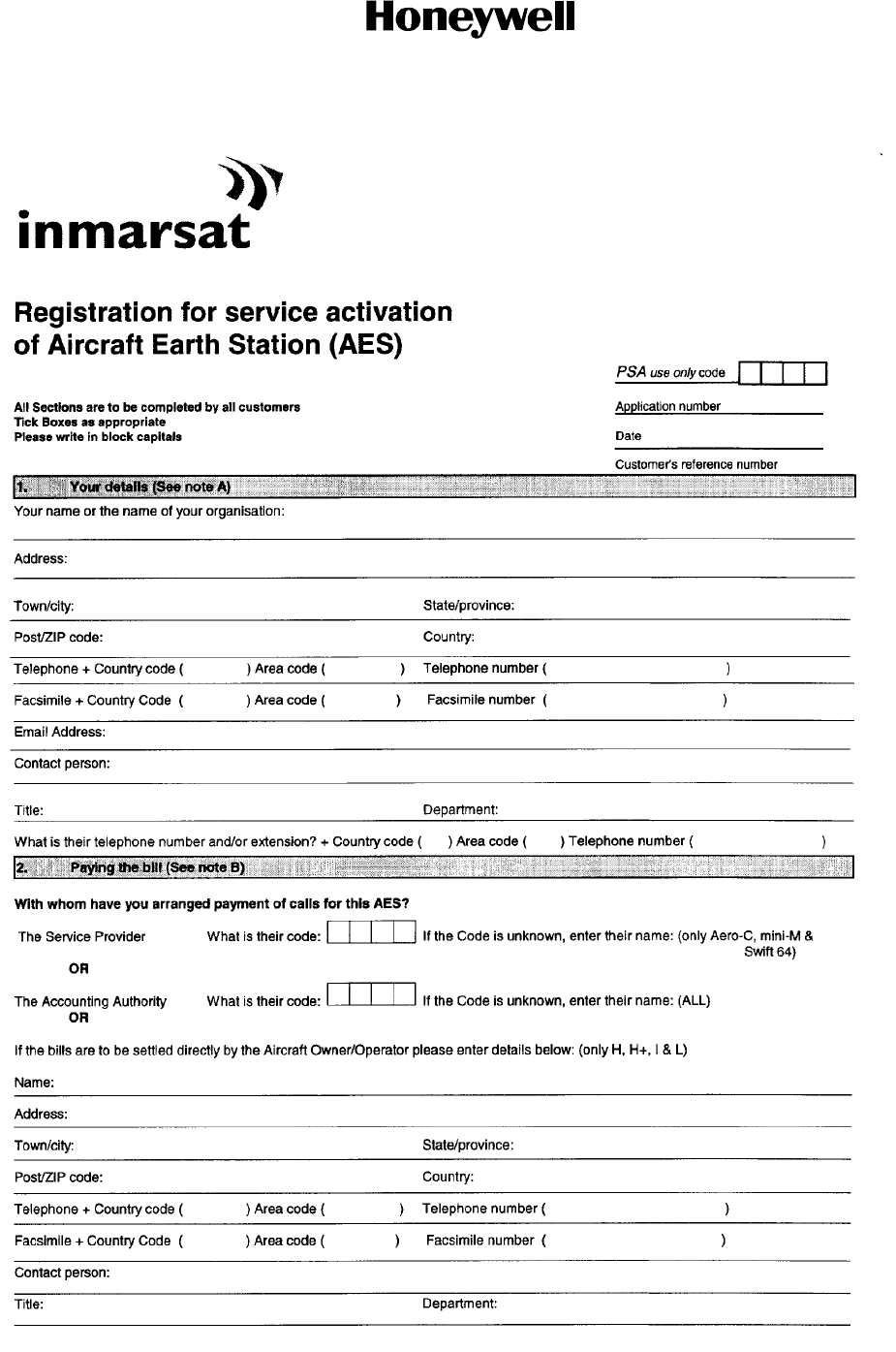
SYSTEM DESCRIPTION AND INSTALLATION MANUAL
HS--600 High Speed Data System
23--20--31
30 May 2002
Use or disclosure of information on this page is subject to the restrictions in the proprietary notice of this document.
Page B--2
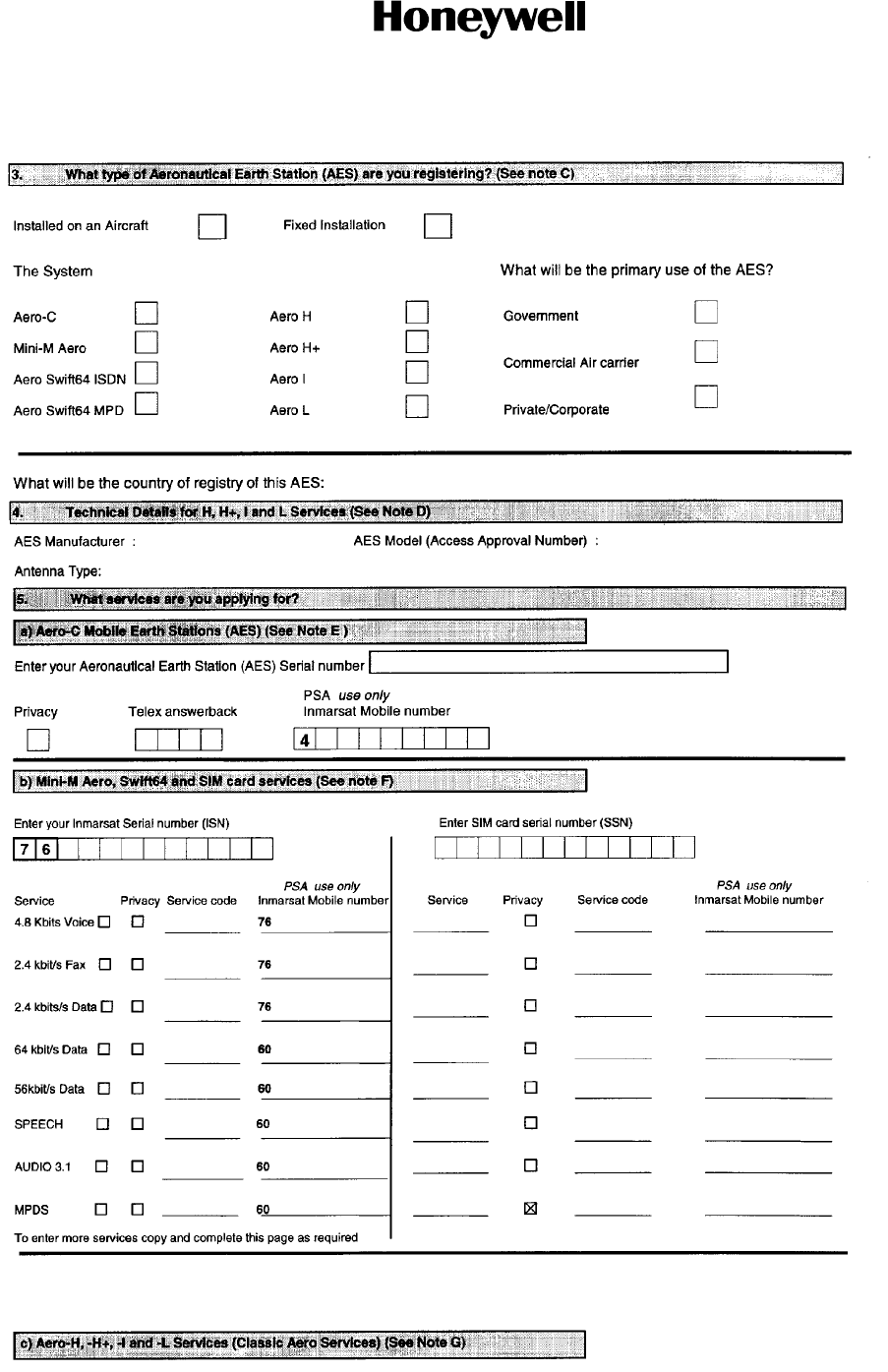
SYSTEM DESCRIPTION AND INSTALLATION MANUAL
HS--600 High Speed Data System
23--20--31
30 May 2002
Use or disclosure of information on this page is subject to the restrictions in the proprietary notice of this document.
Page B--3
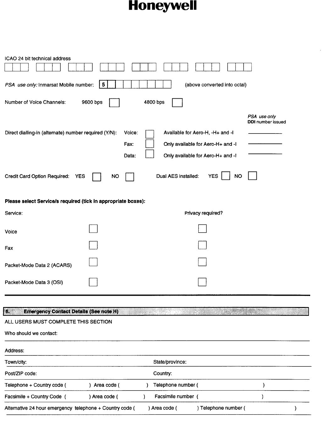
SYSTEM DESCRIPTION AND INSTALLATION MANUAL
HS--600 High Speed Data System
23--20--31
30 May 2002
Use or disclosure of information on this page is subject to the restrictions in the proprietary notice of this document.
Page B--4
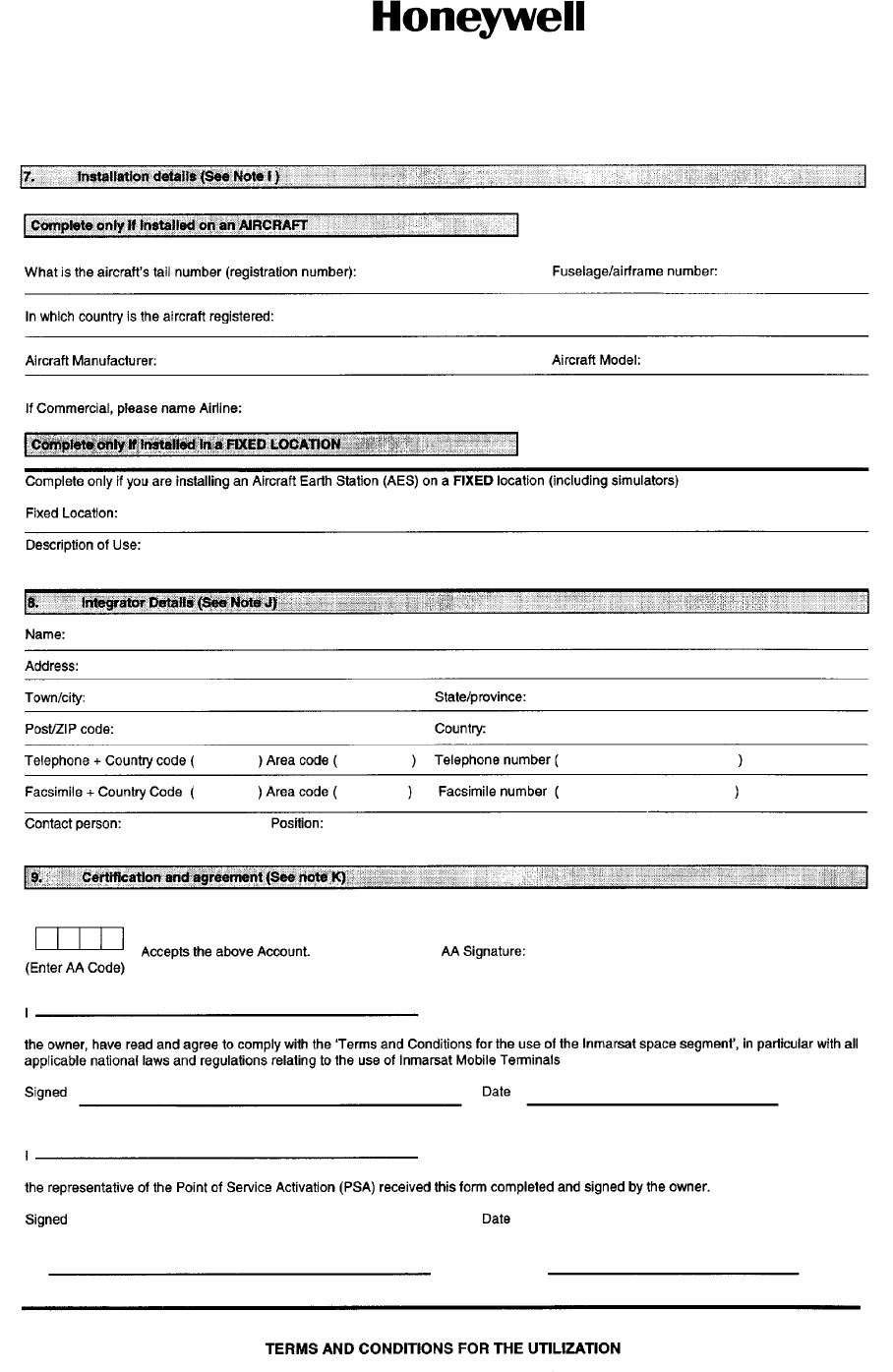
SYSTEM DESCRIPTION AND INSTALLATION MANUAL
HS--600 High Speed Data System
23--20--31
30 May 2002
Use or disclosure of information on this page is subject to the restrictions in the proprietary notice of this document.
Page B--5
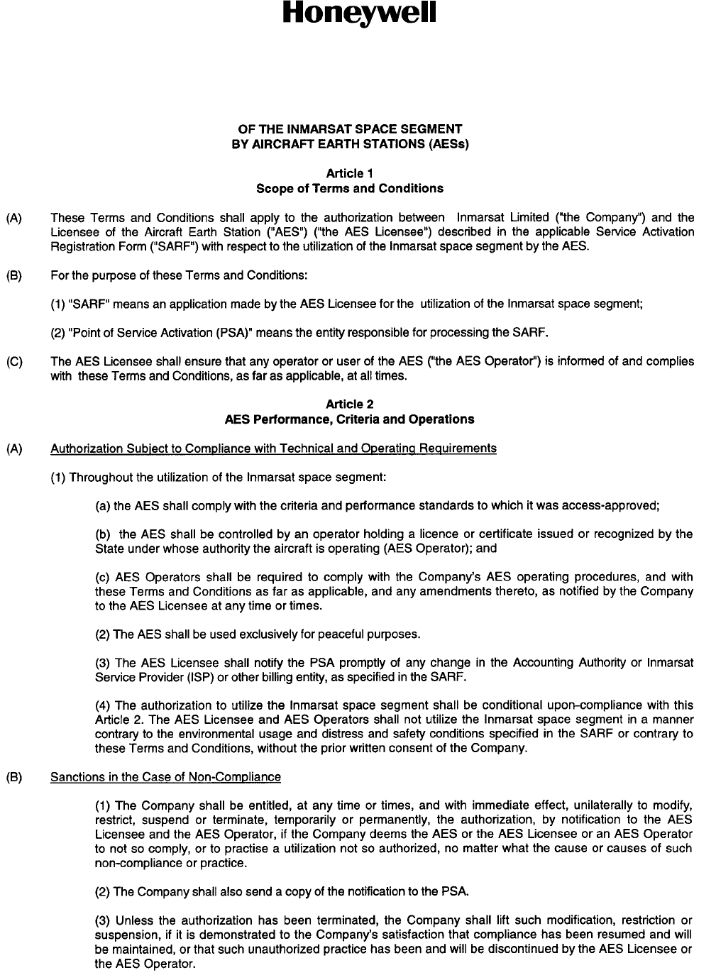
SYSTEM DESCRIPTION AND INSTALLATION MANUAL
HS--600 High Speed Data System
23--20--31
30 May 2002
Use or disclosure of information on this page is subject to the restrictions in the proprietary notice of this document.
Page B--6
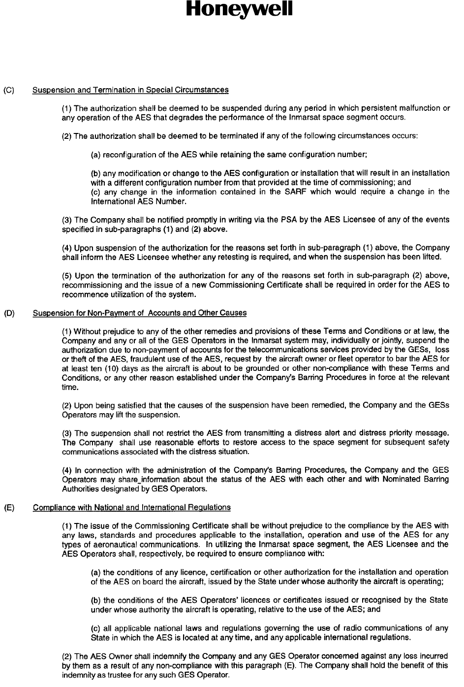
SYSTEM DESCRIPTION AND INSTALLATION MANUAL
HS--600 High Speed Data System
23--20--31
30 May 2002
Use or disclosure of information on this page is subject to the restrictions in the proprietary notice of this document.
Page B--7
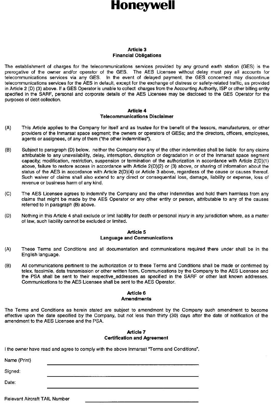
SYSTEM DESCRIPTION AND INSTALLATION MANUAL
HS--600 High Speed Data System
23--20--31
30 May 2002
Use or disclosure of information on this page is subject to the restrictions in the proprietary notice of this document.
Page B--8
SYSTEM DESCRIPTION AND INSTALLATION MANUAL
HS--600 High Speed Data System
23--20--31
30 May 2002
Use or disclosure of information on this page is subject to the restrictions in the proprietary notice of this document.
Page B--9
SYSTEM DESCRIPTION AND INSTALLATION MANUAL
HS--600 High Speed Data System
23--20--31
30 May 2002
Use or disclosure of information on this page is subject to the restrictions in the proprietary notice of this document.
Page B--10