Honeywell HS-700 Inmarsat Aircraft Telecommunications System User Manual
Honeywell International Inc. Inmarsat Aircraft Telecommunications System
UserManual.wiki
>
Honeywell
>
HS 700 User Manual
User Manual
Navigation menu
Upload a User Manual
Namespaces
Wiki Guide
HTML
PDF
Info
Views
User Manual
Discussion / Help
Navigation


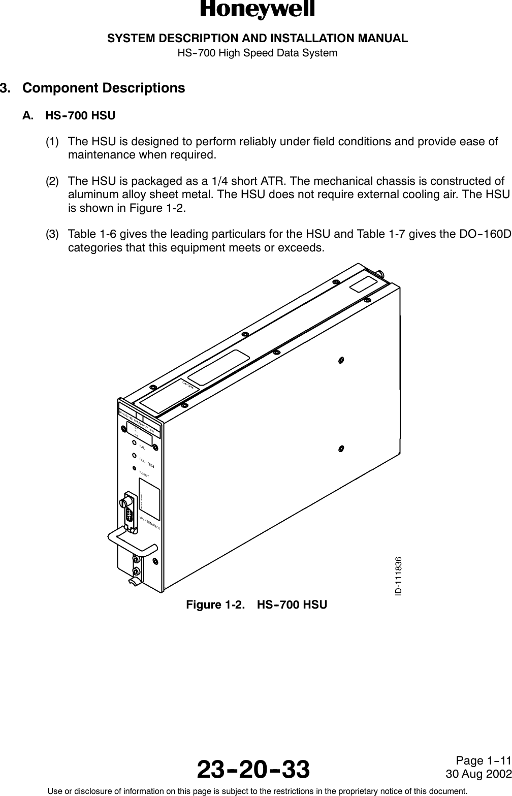
![SYSTEM DESCRIPTION AND INSTALLATION MANUALHS--700 High Speed Data System23--20--3330 Aug 2002Use or disclosure of information on this page is subject to the restrictions in the proprietary notice of this document.Page 1--5F. Control and Status Interfaces(1) The control interfaces include the following:•CMT interfaces•ARINC 429 control interfaces•HSU disable control interface•Discrete outputs.(2) The HSU has two CMT interfaces, one on the front panel and one on the ARINC 404connector at the rear panel. The rear panel interface makes it possible to connect tothe SDU and have the SDU access the HSU’s commissioning and maintenanceterminal (CMT) interface. The front panel interface provides an interface to a personalcomputer (PC) terminal for configuration and maintenance purposes. The CMTinterfaces are used for configuration control, SW downloads, and debug.(3) The debug shell provides access to a series of commands provided for debuggingpurposes. The commands are organized in shells. The active shell can be read fromthe command prompt.(4) The SDU controls the HSU via the ARINC 429 Interface. The HSU operates as aslave to the SDU in cooperative mode. Three levels of communication areimplemented on the ARINC 429 control interface as follows:•Solo words used for block transfers and solo words, for example, high priority andtiming--critical messages.•Periodic words, which are words transmitted at a periodic rate.•SDU/HSU message transfer, which is a high level message transfer byWilliamsburg protocol.(5) The Williamsburg protocol provides detection of errors and retransmissions of failedpackets. The protocol also provides the transmission of data packets spanning morethan one ARINC word.(6) A discrete input is provided for the SDU to disable the HSU. The HSU disable signalinhibits the transmitter output and keeps the HSU reset as long as it is activated.When released, the HSU performs a normal power--on self test (POST) procedure.(7) The HS--700 is supplied with three discrete outputs. One of the outputs is a spare forfuture use (not defined yet). The second is an HSD service availability indicator(ISDN or MPDS). The third is used to indicate failures in the HSU (from built--in testequipment [BITE], person--activated self--test [PAST] and POST).](https://usermanual.wiki/Honeywell/HS-700/User-Guide-322332-Page-27.png)


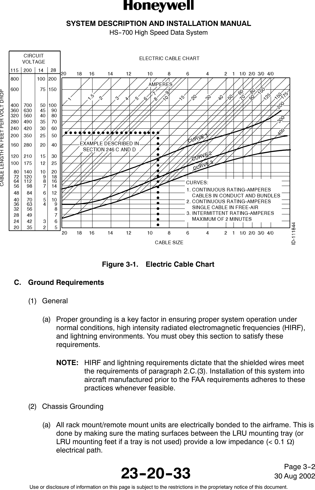
![SYSTEM DESCRIPTION AND INSTALLATION MANUALHS--700 High Speed Data System23--20--3330 Aug 2002Use or disclosure of information on this page is subject to the restrictions in the proprietary notice of this document.Page 3--1SECTION 3ELECTRICAL INSTALLATION1. OverviewA. General(1) This section gives electrical installation procedures, power distribution, andinterconnect information for the HSU, combiner, and splitter.(2) Procedures for proper shield, power, and signal grounding are also provided in thissection. In addition, procedures for the various buses are included.B. Equipment and Materials(1) See leading particulars table for a list of mating connectors required to do theelectrical installation.2. Electrical Installation ProcedureA. General(1) The information necessary to provide the electrical interconnects is contained in thefollowing paragraphs.B. Power Requirements(1) The aircraft dc power supply must be 28 V dc (nominal). The normal minimum andmaximum voltages permitted are 20.5 and 32.2 V dc respectively.(2) Power supply to the HSU -- The voltage level of the power supplied to the HSU isimportant in this installation. The potential is the difference between the power pinsand power ground pins at the line replaceable unit (LRU). Excessive voltage drops inthe power wire(s) and power ground wire(s) cause one or more of the followingconditions:•The LRU draws additional current from the aircraft supply system.•The voltage drop can become large enough that the LRU oscillates on and off atlow line. This oscillation can damage the LRU.(3) The HSU is supplied from the 28 V dc aircraft power system through a separatecircuit breaker. It is essential to keep the impedance of the power supply cablesbelow the limits specified in Table 1-6. The HSU also provides the power supplyvoltages to the CDM.(4) The recommended maximum total combined voltage drop (voltage drop of the powerwire[s] plus voltage drop of the power ground wire[s]) low line input is 1.0 V. Voltagedrop is a function of current and resistance (resistance in this case is a function ofwire gauge and wire length). See Figure 3-1 for determining proper wire gauge for around trip length of LRU power and power ground wires.](https://usermanual.wiki/Honeywell/HS-700/User-Guide-322332-Page-49.png)