Honeywell HS-700 Inmarsat Aircraft Telecommunications System User Manual
Honeywell International Inc. Inmarsat Aircraft Telecommunications System
User Manual

This document contains technical data and is subject to U.S. export regulations.
These commodities, technology, or software were exported from the United States in accordance with the
export administration regulations. Diversion contrary to U.S. law is prohibited.
Honeywell
Aerospace Electronic Systems
CES--Phoenix
P.O. Box 21111
Phoenix, Arizona 85036-1111
U.S.A.
Printed in U.S.A. Pub. No. A15--5111--007
23--20--33
Title Page T--1
30 Aug 2002
System Description and Installation
Manual
HS--700
High Speed Data System

SYSTEM DESCRIPTION AND INSTALLATION MANUAL
HS--700 High Speed Data System
PROPRIETARY NOTICE
This document and the information disclosed herein are proprietary data of Honeywell. Neither
this document nor the information contained herein shall be used, reproduced, or disclosed to
others without the written authorization of Honeywell, except to the extent required for
installation or maintenance of the recipient’s equipment.
NOTICE -- FREEDOM OF INFORMATION ACT (5 USC 552) AND
DISCLOSURE OF CONFIDENTIAL INFORMATION GENERALLY (18 USC 1905)
This document is being furnished in confidence by Honeywell. The information disclosed
herein fall within exemption (b) (4) of 5 USC 552 and the prohibitions of 18 USC 1905.
S2002
Honeywell is a U.S. registered trademark of Honeywell. All other marks are owned by their respective companies.
Copyright 2002 Honeywell
All Rights Reserved
23--20--33
Title Page T--2
30 Aug 2002
Please cut along the dotted line.Please cut along the dotted line.
REPORT OF POSSIBLE DATA ERROR
FOR HONEYWELL USE ONLY
CONTROL NO.
DATE RECEIVED
Please mail or FAX completed form to Technical Publications Quality Administrator. If returning by mail, please tape this form closed (U.S. postal
regulations prohibit the use of staples). If sending by FAX, the Technical Publications’ U.S. FAX No. is (602- 436- 3900). If sending by email, the email address
is tpqa@honeywell.com.
Local reproduction of this form is encouraged. This form is based on electronic form INF--300, Revision 0
To help us improve the quality of our publication, Honeywell encourages any report of a possible data error.
PUBLICATION INFORMATION
Publication
Number
A15-- 5111--007
Volume No.
(Book, or
Addendum)
ATA
Number
23--20--33
Latest Issue Date
From Title Page
Publication
Title
High Speed Data Unit
Document
Type
System Description and Installation
Manual
READER INFORMATION
Please check all that apply:
hTrainer hTechnician hLibrarian hEngineer hOther
(Please specify)
Your Name (optional) Company Name
Street Address City, State (Province),
Zip Code, Country
Telephone No. FAX No.
POSSIBLE DATA ERROR
Page
No.
Paragraph
Figure No. Table No. Description of Possible Data Error
HONEYWELL REPLY
DO NOT STAPLE
DO NOT STAPLE
BUSINESS REPLY MAIL
FIRST CLASS PERMIT NO. 3532, PHOENIX, AZ
FOLD
FOLD
POSTAGE WILL BE PAID BY ADDRESSEE
Honeywell
Aerospace Electronic Systems
CES--Phoenix
P.O. Box 21111
Phoenix, Arizona 85036-1111
U.S.A.
ATTN: Technical Publications
Quality Administrator
NO POSTAGE
NECESSARY
IF MAILED
IN THE
UNITED STATES
Please cut along the dotted line.Please cut along the dotted line.
CUSTOMER RESPONSE
FOR HONEYWELL USE ONLY
CONTROL NO.
DATE RECEIVED
Please mail or FAX completed form to Technical Publications Quality Administrator. If returning by mail, please tape closed (U.S. postal regulations prohibit
the use of staples). If sending by FAX, the Technical Publications’ U.S. FAX No. is (602- 436- 3900). If sending by email, the email address is
tpqa@honeywell.com.
Local reproduction of this form is encouraged.
To help us improve the quality of our publications, Honeywell encourages readers to provide input to the
customer--satisfaction survey below. We welcome all comments and recommendations.
PUBLICATION INFORMATION
Publication
Number
A15-- 5111--007
Volume No.
(Book, or
Addendum)
ATA
Number
23--20--33
Latest Issue Date
From Title Page
Publication
Title
High Speed Data Unit
Document
Type
System Description and Installation Manual
READER INFORMATION
Please check all that apply:
hTrainer hTechnician hLibrarian hEngineer hOther
(Please specify)
Your Name (optional) Company Name
S
t
r
e
e
t
A
d
d
r
e
s
s
C
i
t
y
,S
t
a
t
e
(
P
ro
v
i
nce
)
,
S
t
ree
t
A
d
d
ress
C
i
t
y
,
S
t
a
t
e
(
P
r
o
v
i
n
c
e
)
,
Zip Code, Country
Telephone No. FAX No.
CUSTOMER--SATISFACTION SURVEY
Please check the yes or no box to answer the following questions: Yes No
1. Is the Publication technically accurate?
j j
2. Is information easy to find?
j j
3. Is information complete?
j j
4. Are figures easy to use?
j j
5. Are tables easy to use
j j
6. Is the Publication used for training?
j j
7. Do you or your organization wish to remain on distribution for this publication?
j j
Please rate this publication in comparison to other documents you use. Good Fair Poor
jjj
Please provide comments, recommendations and/or improvements that you would like to see in this publication.
DO NOT STAPLE
DO NOT STAPLE
BUSINESS REPLY MAIL
FIRST CLASS PERMIT NO. 3532, PHOENIX, AZ
FOLD
FOLD
POSTAGE WILL BE PAID BY ADDRESSEE
Honeywell
Aerospace Electronic Systems
CES--Phoenix
P.O. Box 21111
Phoenix, Arizona 85036-1111
U.S.A.
ATTN: Technical Publications
Quality Administrator
NO POSTAGE
NECESSARY
IF MAILED
IN THE
UNITED STATES

SYSTEM DESCRIPTION AND INSTALLATION MANUAL
HS--700 High Speed Data System
23--20--33
30 Aug 2002
Use or disclosure of information on this page is subject to the restrictions in the proprietary notice of this document.
Page RR--1
RECORD OF REVISIONS
For each revision, put the revised pages in your manual and discard the superseded pages. Write
the revision number and date, date put in manual, and the incorporator’s initials in the applicable
columns on the Record of Revisions. The initial H shows Honeywell is the incorporator.
Revision
Number
Revision
Date
Date Put
In Manual By
Revision
Number
Revision
Date
Date Put
In Manual By

SYSTEM DESCRIPTION AND INSTALLATION MANUAL
HS--700 High Speed Data System
23--20--33
30 Aug 2002
Use or disclosure of information on this page is subject to the restrictions in the proprietary notice of this document.
Page RR--2
Blank Page

SYSTEM DESCRIPTION AND INSTALLATION MANUAL
HS--700 High Speed Data System
23--20--33
30 Aug 2002
Use or disclosure of information on this page is subject to the restrictions in the proprietary notice of this document.
Page RTR--1
RECORD OF TEMPORARY REVISIONS
Instructions on each page of a temporary revision tell you where to put the pages in your manual.
Remove temporary revision pages only when discard instructions are given. For each temporary
revision, put the applicable data in the record columns on this page.
Temporary
Revision
Number
Temporary
Revision
Date
Temporary
Revision
Status
Date Put
in Manual By *
Date
Removed
from Manual By *
* The initial H in this column shows Honeywell has done this task.

SYSTEM DESCRIPTION AND INSTALLATION MANUAL
HS--700 High Speed Data System
23--20--33
30 Aug 2002
Use or disclosure of information on this page is subject to the restrictions in the proprietary notice of this document.
Page RTR--2
Blank Page

SYSTEM DESCRIPTION AND INSTALLATION MANUAL
HS--700 High Speed Data System
23--20--33
30 Aug 2002
Use or disclosure of information on this page is subject to the restrictions in the proprietary notice of this document.
Page SBL--1
SERVICE BULLETIN LIST
Service Bulletin
Identified
Mod
Date Included
in this Manual Description

SYSTEM DESCRIPTION AND INSTALLATION MANUAL
HS--700 High Speed Data System
23--20--33
30 Aug 2002
Use or disclosure of information on this page is subject to the restrictions in the proprietary notice of this document.
Page SBL--2
Blank Page

SYSTEM DESCRIPTION AND INSTALLATION MANUAL
HS--700 High Speed Data System
23--20--33
30 Aug 2002
Use or disclosure of information on this page is subject to the restrictions in the proprietary notice of this document.
Page TC--1
TABLE OF CONTENTS
Subject Page
INTRODUCTION INTRO--1...........................................................
1. Proprietary, Export, and Precautionary Data INTRO--1...............................
A. Proprietary Notice INTRO--1..................................................
B. Export Notice INTRO--1......................................................
C. Special Precautions INTRO--1................................................
2. Content Data INTRO--2..........................................................
A. How to Use This Manual INTRO--2............................................
B. Weights and Measurements INTRO--2.........................................
C. Acronyms and Abbreviations INTRO--3.........................................
3. Customer Assistance INTRO--4...................................................
A. Who to Contact INTRO--4....................................................
SECTION 1
SYSTEM DESCRIPTION AND OPERATION
1--1...........................................................................
1. Overview 1--1..............................................................
A. General 1--1...........................................................
B. Aero--H/H+ 1--2........................................................
C. Services 1--3..........................................................
D. User Interfaces 1--3.....................................................
E. Service Routing 1--4....................................................
F. Control Interfaces and Status 1--5........................................
G. CDM 1--6..............................................................
H. Boot Loader 1--6.......................................................
I. BITE 1--7..............................................................
(1) General 1--7.......................................................
(2) POST 1--7.........................................................
(3) PAST 1--7.........................................................
(4) CM 1--7...........................................................
(5) Performed Tests 1--7................................................
J. Cable Loss 1--7........................................................

SYSTEM DESCRIPTION AND INSTALLATION MANUAL
HS--700 High Speed Data System
23--20--33
30 Aug 2002
Use or disclosure of information on this page is subject to the restrictions in the proprietary notice of this document.
Page TC--2
Subject Page
K. Power Management 1--8................................................
(1) General 1--8.......................................................
(2) Power Allocation 1--8...............................................
(3) Power Adjustment 1--9..............................................
(4) Power Preemption 1--9..............................................
2. System Components 1--10...................................................
A. General 1--10...........................................................
3. Component Descriptions 1--11................................................
A. HS--700 HSU 1--11......................................................
B. CDM 1--15..............................................................
C. RF Splitter/Combiner 1--17...............................................
D. HSU Mounting Tray 1--17.................................................
SECTION 2
MECHANICAL INSTALLATION 2--1.............................................
1. Overview 2--1..............................................................
A. General 2--1...........................................................
B. Equipment and Materials 2--1............................................
2. Mechanical Installation Design 2--1...........................................
A. HS--700 HSU Provisions 2--1............................................
B. CDM Provisions 2--1....................................................
C. RF Splitter/Combiner Provisions 2--1......................................
SECTION 3
ELECTRICAL INSTALLATION 3--1..............................................
1. Overview 3--1..............................................................
A. General 3--1...........................................................
B. Equipment and Materials 3--1............................................
2. Electrical Installation Procedure 3--1..........................................
A. General 3--1...........................................................
B. Power Requirements 3--1...............................................
C. Ground Requirements 3--2..............................................
(1) General 3--2.......................................................
(2) Chassis Grounding 3--2.............................................
(3) Shield Grounds 3--3................................................
(4) Power/Signal Grounds 3--4..........................................

SYSTEM DESCRIPTION AND INSTALLATION MANUAL
HS--700 High Speed Data System
23--20--33
30 Aug 2002
Use or disclosure of information on this page is subject to the restrictions in the proprietary notice of this document.
Page TC--3
Subject Page
3. Electrical Installation 3--6....................................................
A. HSU 3--6..............................................................
(1) General 3--6.......................................................
(2) HSU X1 Connector 3--6.............................................
(3) HSU X2 Connector 3--7.............................................
(4) HSU X3 Connector 3--9.............................................
B. CDM 3--10..............................................................
SECTION 4
INSTALLATION CHECK 4--1....................................................
1. Overview 4--1..............................................................
A. General 4--1...........................................................
SECTION 5
ADJUSTMENT/TEST 5--1.......................................................
1. Overview 5--1..............................................................
A. General 5--1...........................................................
SECTION 6
FAULT ISOLATION 6--1........................................................
1. Overview 6--1..............................................................
A. General 6--1...........................................................
SECTION 7
MAINTENANCE PRACTICES 7--1...............................................
1. Overview 7--1..............................................................
A. General 7--1...........................................................
B. Equipment and Materials 7--1............................................
2. Procedure for the HS--700 HSU 7--1..........................................
A. Removal and Reinstallation Procedures 7--1...............................
B. Adjustment Procedures 7--2.............................................
C. Repair Procedures 7--2.................................................
D. Return to Service Procedures 7--2........................................
3. Procedure for the CDM 7--3.................................................
A. Removal and Reinstallation Procedures 7--3...............................
B. Adjustment Procedures 7--3.............................................
C. Repair Procedures 7--3.................................................
D. Return to Service Procedures 7--3........................................

SYSTEM DESCRIPTION AND INSTALLATION MANUAL
HS--700 High Speed Data System
23--20--33
30 Aug 2002
Use or disclosure of information on this page is subject to the restrictions in the proprietary notice of this document.
Page TC--4
Subject Page
4. Procedure for the Combiner/Splitter 7--3......................................
A. Removal and Reinstallation Procedures 7--3...............................
B. Adjustment Procedures 7--4.............................................
C. Repair Procedures 7--4.................................................
D. Return to Service Procedures 7--4........................................
5. Instructions for Continued Airworthiness, Code of Federal Regulation
CFR 91.213 7--5...........................................................
A. General 7--5...........................................................
B. Instructions 7--5........................................................
APPENDIX A
INMARSAT REGISTRATION FORM A--1..........................................
1. Overview A--1..............................................................
A. General A--1...........................................................
List of Illustrations
Figure Page
Figure 1-1. High Speed Data System Block Diagram 1--2..........................
Figure 1-2. HS--700 HSU 1--11..................................................
Figure 1-3. CDM 1--15..........................................................
Figure 1-4. RF Splitter/Combiner 1--17............................................
Figure 2-1 (Sheet 1). HSU Outline and Installation Diagram 2--3....................
Figure 2-1 (Sheet 2). HSU Outline and Installation Diagram 2--5....................
Figure 2-2. Mounting Tray Outline and Installation Diagram 2--7....................
Figure 2-3. CDM Outline and Installation Diagram 2--9............................
Figure 2-4. RF Splitter/Combiner Outline Diagram 2--11..............................
Figure 3-1. Electric Cable Chart 3--2............................................
Figure 3-2. Example 1, Multi--point Shield Ground 3--3............................
Figure 3-3. Example 2, Multi--point Shield Ground 3--3............................
Figure 3-4. Shield Grounding Example for Rack Mount Connectors 3--4.............
Figure 3-5. Aircraft Grounding 3--5..............................................
Figure 3-6. HSU Interface Block Diagram 3--6....................................
Figure 3-7. HSU Maintenance Connector (X1) Pin Layout 3--7......................
Figure 3-8. HSU ARINC 404 Connector (X2) Pin Layout 3--8.......................

SYSTEM DESCRIPTION AND INSTALLATION MANUAL
HS--700 High Speed Data System
23--20--33
30 Aug 2002
Use or disclosure of information on this page is subject to the restrictions in the proprietary notice of this document.
Page TC--5
List of Illustrations (cont)
Figure Page
Figure 3-9. HSU CDM Connector (X3) Pin Layout 3--10.............................
Figure 3-10. HS--700 High Speed Data System Interconnect Diagram 3--11...........
List of Tables
Table Page
Table Intro--1. Related Publications INTRO--2.........................................
Table 1-1. Type of Service 1--2.................................................
Table 1-2. Service Routing 1--4................................................
Table 1-3. Power Allocation 1--8................................................
Table 1-4. Components Supplied by Honeywell 1--10..............................
Table 1-5. Components/Parts Not Supplied by Honeywell 1--10.....................
Table 1-6. HS--700 Leading Particulars 1--12.....................................
Table 1-7. DO--160D Environmental Categories 1--14..............................
Table 1-8. HSU Front Panel Description 1--15.....................................
Table 1-9. CDM Leading Particulars 1--16........................................
Table 1-10. HSU Mounting Trays 1--18...........................................
Table 3-1. HSU X1 Connector Pin Assignments 3--7..............................
Table 3-2. HSU X2 Connector Pin Assignments 3--8..............................
Table 3-3. HSU X3 Connector Pin Assignments 3--10..............................

SYSTEM DESCRIPTION AND INSTALLATION MANUAL
HS--700 High Speed Data System
23--20--33
30 Aug 2002
Use or disclosure of information on this page is subject to the restrictions in the proprietary notice of this document.
Page TC--6
Blank Page

SYSTEM DESCRIPTION AND INSTALLATION MANUAL
HS--700 High Speed Data System
23--20--33
30 Aug 2002
Use or disclosure of information on this page is subject to the restrictions in the proprietary notice of this document.
Page INTRO--1
INTRODUCTION
1. Proprietary, Export, and Precautionary Data
A. Proprietary Notice
(1) This document and the information disclosed herein are proprietary data of
Honeywell. Neither this document nor the information contained herein shall be used,
reproduced, or disclosed to others without the written authorization of Honeywell,
except to the extent required for installation or maintenance of the recipient’s
equipment. FREEDOM OF INFORMATION ACT (5 USC 552) AND DISCLOSURE
OF CONFIDENTIAL INFORMATION GENERALLY (18 USC 1905).
(2) This document is being furnished in confidence by Honeywell. The information
disclosed herein falls within exemption (b) (4) of 5 USC 552 and the prohibitions of 18
USC 1905. Copyright 2002 Honeywell. All Rights Reserved.
(3) Honeywell is a U.S. registered trademark of Honeywell. All other marks are owned by
their respective companies.
B. Export Notice
(1) This document contains unrestricted technical data and is being exported under
license exception TSU/OTS in accordance with EAR Section 740.13(a).
(2) These commodities, technology, or software were exported from the United States in
accordance with the export administration regulations. Diversion contrary to U.S. law
is prohibited. ECCN: 7E994 Schedule B#4901.99.0050
C. Special Precautions
(1) Warnings, cautions, and notes in this manual give the data that follows:
•A WARNING is an operation or maintenance procedure or condition that, if not
obeyed, can cause injury or death.
•A CAUTION is an operation or maintenance procedure or condition that, if not
obeyed, can cause damage to the equipment.
•A NOTE gives data to make the work easier or gives directions to go to a
procedure.
(2) All personnel who operate equipment and do maintenance specified in this manual
must know and obey the safety precautions. The warnings and cautions that follow
apply to all parts of this manual.

SYSTEM DESCRIPTION AND INSTALLATION MANUAL
HS--700 High Speed Data System
23--20--33
30 Aug 2002
Use or disclosure of information on this page is subject to the restrictions in the proprietary notice of this document.
Page INTRO--2
WARNING: BEFORE YOU USE A MATERIAL, REFER TO THE MANUFACTURERS’
MATERIAL SAFETY DATA SHEETS FOR SAFETY INFORMATION. SOME
MATERIALS CAN BE DANGEROUS.
CAUTION: DO NOT USE MATERIALS THAT ARE NOT EQUIVALENT TO
MATERIALS SPECIFIED BY HONEYWELL. MATERIALS THAT ARE NOT
EQUIVALENT CAN CAUSE DAMAGE TO THE EQUIPMENT AND CAN
VOID THE WARRANTY.
CAUTION: THE HS--700 HIGH SPEED DATA SYSTEM CONTAINS ITEMS THAT ARE
ELECTROSTATIC DISCHARGE SENSITIVE (ESDS). IF YOU DO NOT
OBEY THE NECESSARY CONTROLS, A FAILURE OR
UNSATISFACTORY OPERATION OF THE UNIT CAN OCCUR FROM
ELECTROSTATIC DISCHARGE. USE APPROVED INDUSTRY
PRECAUTIONS TO KEEP THE RISK OF DAMAGE TO A MINIMUM WHEN
YOU TOUCH, REMOVE, OR INSERT PARTS OR ASSEMBLIES.
2. Content Data
A. How to Use This Manual
(1) This manual gives general system description and installation information for the
HS--700 High Speed Data System. It also gives block diagram and interconnect
information to permit a general understanding of the system interface.
(2) The purpose of this manual is to help you install, operate, maintain, and troubleshoot
the HS--700 High Speed Data System. Common system maintenance procedures
are not presented in this manual. The best established shop and flight line practices
should be used.
(3) Related publications that are referred to in this manual are identified in Table Intro--1.
Table Intro--1. Related Publications
Publication Publication No.
Handling, Storage, and Shipping Procedures for Honeywell Avionics
Equipment Instruction Manual
A09--1100--001
MCS--4000/7000 Multi--Channel SATCOM System Description,
Installation, and Maintenance Manual
A15-- 5111 -- 001
NOTES:
1. You can order a Honeywell publication from Honeywell as follows:
Telephone No.: (602) 436--6900
Fax No.: (602) 436--1588
E--mail: cas--publications--distribution@honeywell.com
B. Weights and Measurements
(1) All weights and measurements are in U. S. values.
(2) The letter symbols for units of measurement are the same as shown in
ANSI/IEEE Std 260.

SYSTEM DESCRIPTION AND INSTALLATION MANUAL
HS--700 High Speed Data System
23--20--33
30 Aug 2002
Use or disclosure of information on this page is subject to the restrictions in the proprietary notice of this document.
Page INTRO--3
C. Acronyms and Abbreviations
(1) The acronyms and abbreviations that follow help the reader identify terms and
definitions used by Honeywell.
(2) The letter symbols for units of measurement are the same as shown in
ANSI/IEEE Std 260.
Term Definition
ACSE access control and signalling equipment
ACU antenna control unit
BSU beam steering unit
CCA circuit card assembly
CDM configuration data module
CMT commissioning and maintenance terminal
CNS/ATM communication, navigation, and surveillance/air traffic management
DCE data circuit--terminating equipment
DLNA diplexer/low noise amplifier
ESD electrostatic discharge
ESDS electrostatic discharge sensitive
HGA high gain antenna
HIRF high intensity radiated electromagnetic frequencies
HPA high power amplifier
HSD high speed data
HSU high speed data unit
ICAO International Civil Aviation Organization: Agency of the UN
IETF Internet Engineering Task Force
IPC Illustrated Parts Catalog
IPDS Inmarsat Packet Mode Data Service
IRS inertial reference system
ISDN Integrated Services Digital Network
LES land earth station
LESA land earth station assignment
LRU line replaceable unit
MCS multi--channel SATCOM
MCU modular concept unit
MEL minimum equipment list
MES Mobile Earth Station
MM/HSD Mini M/high speed data

SYSTEM DESCRIPTION AND INSTALLATION MANUAL
HS--700 High Speed Data System
23--20--33
30 Aug 2002
Use or disclosure of information on this page is subject to the restrictions in the proprietary notice of this document.
Page INTRO--4
Term Definition
MTBF mean--time--between--failures
NCSA network coordination station assignment
NT network termination
PC personal computer
PID personal identification number
PSTN Public Switched Telephone Network
RF radio frequency
RFC request for comments
RFU radio frequency unit
SATCOM satellite communications
SCPC single channel per circuit
SDM System Definition Manual
SDU satellite data unit
SU signal unit
TA terminal adapter
TDM time division multiplex
TE terminal equipment
TDMA time division multiple access
3. Customer Assistance
A. WhotoContact
(1) For assistance with installation, operation, or maintenance of the HS--700 High
Speed Data System, contact your local Honeywell Dealer or regional Honeywell
Customer Support Engineer. Additional assistance can be obtained from:
•Honeywell
Aviation Services, Customer Response Center (CRC)
Commercial Electronic Systems
21111 N. 19th Avenue
Phoenix, AZ 85027
TEL: (877) 436--2005 (Toll--Free)
FAX: (602) 436--1501

SYSTEM DESCRIPTION AND INSTALLATION MANUAL
HS--700 High Speed Data System
23--20--33
30 Aug 2002
Use or disclosure of information on this page is subject to the restrictions in the proprietary notice of this document.
Page 1--1
SECTION 1
SYSTEM DESCRIPTION AND OPERATION
1. Overview
A. General
(1) The HS--700 high speed data (HSD) system is designed to form part of the
MCS--7000 Aero H/H+ satellite communication (SATCOM) system. The MCS--7000
multi--channel SATCOM (MCS) system includes a SD--700 satellite data unit (SDU),
HP--600 high power amplifier (HPA), and Aero--H/H+ high gain antenna (HGA). The
HS--700 high speed data unit (HSU) provides an additional dedicated 64 kbps
integrated services digital network (ISDN) or mobile packet data service (MPDS)
channel that can be operated simultaneously with the MCS--7000 SATCOM system.
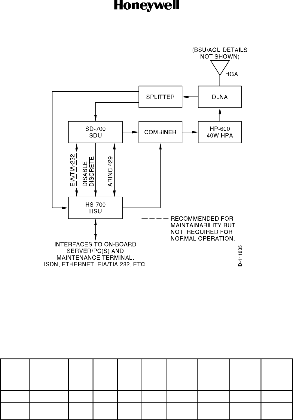
(2) Figure 1-1 shows how the HSU interconnects to the MCS--7000 SATCOM system.
The HSU is operated as a slave to the MCS system in cooperative mode. The
SD--700 SDU controls the slave HSU through a high speed ARINC 429 bus and a
disable discrete.
(3) The HSU is a terminal for data, fax, and voice communications through the Inmarsat
global area network (GAN). It provides the services of this network to the user. The
user can access these services through the user interfaces of the terminal.
(4) The L--band radio frequency (RF) transmit outputs of the HSU and the SDU are
combined with an RF combiner. The output of the RF combiner drives a common 40
W HPA, the diplexer portion of the diplexer/low noise amplifier (DLNA), and nominal
12 dB gain antenna. The SDU manages the satellite selection and steers the HGA.
(5) The L--band RF signals received from the satellite by the HGA and amplified by the
low noise amplifier in the DLNA are divided in two by the RF splitter. One signal set is
connected to and processed by the SDU. The other signal set is connected to and
processed by the HSU. In this way, full duplex communication is achieved for all parts
of the system (MCS--7000 and HS--700).
(6) The MCS--7000 SDU and HPA require only operational software modifications to
properly operate with the HS--700.
SYSTEM DESCRIPTION AND INSTALLATION MANUAL
HS--700 High Speed Data System
23--20--33
30 Aug 2002
Use or disclosure of information on this page is subject to the restrictions in the proprietary notice of this document.
Page 1--2
Figure 1-1. High Speed Data System Block Diagram
B. Aero--H/H+
(1) Aero--H/H+ is a multi--channel aeronautical system that can operate in both the
Inmarsat--3 global and spot beams using either a fuselage-- or tail--mounted HGA.
The type of antenna and the global/spot beam operation identify the type of service
possible as given in Table 1-1.
Table1-1. TypeofService
Aero
Type Antenna
Global
Beam
Spot
Beam
Voice
9.6
kbps
Voice
4.8
kbps
Secure
Voice 4.8
kbps
Fax
(max)
PC Data
(max)
Packet
Mode
Data
(max)
Aero--H High gain Yes No Yes No Yes 4.8 kbps 2.4 kbps 10.5 kbps
Aero--H+ High gain Yes Yes Yes Yes Yes 4.8/2.4
kbps
2.4 kbps 10.5 kbps

SYSTEM DESCRIPTION AND INSTALLATION MANUAL
HS--700 High Speed Data System
23--20--33
30 Aug 2002
Use or disclosure of information on this page is subject to the restrictions in the proprietary notice of this document.
Page 1--3
(2) When used within the spot beams, the Aero--H+ service requires less power so that
call charges are reduced.
(3) All Honeywell/Thales aeronautical equipment complies with the International Civil
Aviation Organization (ICAO) Agency of the UN requirements for aeronautical safety
services. The equipment can be used for communication, navigation, and
surveillance/air traffic management (CNS/ATM).
C. HSD Services
(1) The HS--700 HSD system provides two modes of communication: circuit--mode and
packet--mode. In these modes, there are five services provided as follows:
•ISDN speech, typically used for ISDN telephones and Public Switched Telephone
Network (PSTN) telephones connected with a terminal adapter (TA).
•3.1 kHz audio, typically used for analog data modems, group 3 fax machines, and
secure telephone unit (STU) terminals connected through a TA.
•56 kbps unrestricted digital information (UDI) which is provided for compatibility
with equipment requiring this service.
•64 kbps UDI, typically used for video terminals, group 4 fax machines, data
communication, and secure telephone equipment (STE) terminals.
•MPDS, which is used for internet access and access to corporate local area
networks (LAN) through the virtual private network (VPN) service.
(2) The first four services are circuit--mode services and MPDS is a packet--mode
service.
D. User Interfaces
(1) The services of the HS--700 HSD system can be accessed through three interfaces:
•ISDN NT1 (European S/T Interface)
•EIA/TIA--232 Asynchronous Serial Port
•10BASE--T Ethernet Port.
(2) The ISDN network termination 1 (NT1) interface is the access point for all
circuit--mode services. This interface is physically located on the ARINC--404
connector on the rear of the HSU. Except for the physical design of the connector,
this interface is ISDN compliant. The HS--700 is configured as NT1 for direct
connection to the user’s terminal equipment 1 (TE1) interface, or for connection to
terminal equipement 2 (TE2) through an external terminal adapter (TA).
(3) The HS--700 includes an internal 100 ohm termination resistor for the ISDN interface
to support cable lengths longer than three meters.
(4) The ISDN interface can supply power to up to four ISDN devices, but supports up to
eight devices if at least four of them have their own power supply. During primary
power interruptions of up to 200 ms duration, the HS--700 is capable of maintaining
hold--up with no more than one ISDN device being powered by the HS--700. For
example, if more than one such phone is connected and an incoming call is received
during a 200 ms power interrupt, the HS--700 may reset rather than hold--up over the
power interruption.

SYSTEM DESCRIPTION AND INSTALLATION MANUAL
HS--700 High Speed Data System
23--20--33
30 Aug 2002
Use or disclosure of information on this page is subject to the restrictions in the proprietary notice of this document.
Page 1--4
(5) The EIA/TIA--232 asynchronous serial port interface is the primary access point for
MPDS. The port provides a standard modem interface with a Hayes compatible AT
style command set. For the data communication, the port operates in the point to
point protocol (PPP) mode. The HS--700 is configured as data circuit--terminating
equipment (DCE), using hardware flow control (RTS/CTS) and operating at 115.2
kbps.
(6) The 10BASE--T Ethernet port is an alternate access point for MPDS. The interface
implements a standard 10BASE--T Ethernet port, except for the connector. MPDS is
accessed using the point to point protocol over Ethernet (PPPoE). Only one of the
two MPDS interfaces (10BASE--T or EIA/TIA--232--E) can be used at a time. The port
to be enabled is selected during the configuration of the HSU. The MPDS interface
configuration settings are stored in the configuration data module (CDM). The
HS--700 is configured as an Ethernet hub (DCE).
E. Service Routing
(1) Table 1-2 illustrates the routing or mapping of calls of a certain service to the
corresponding interface in the HS--700 system.
Table 1-2. Service Routing
Service/Interface ISDN Ethernet EIA/TIA--232
ISDN Speech Yes No No
3.1 kHz Audio Yes No No
64 kbps UDI Yes No (Note) No (Note)
56 kbps UDI Yes No (Note) No (Note)
MPDS No Yes Yes
NOTE: Hardware for these combinations are implemented but no software is implemented in the initial version of the
HS--700 system.

SYSTEM DESCRIPTION AND INSTALLATION MANUAL
HS--700 High Speed Data System
23--20--33
30 Aug 2002
Use or disclosure of information on this page is subject to the restrictions in the proprietary notice of this document.
Page 1--5
F. Control and Status Interfaces
(1) The control interfaces include the following:
•CMT interfaces
•ARINC 429 control interfaces
•HSU disable control interface
•Discrete outputs.
(2) The HSU has two CMT interfaces, one on the front panel and one on the ARINC 404
connector at the rear panel. The rear panel interface makes it possible to connect to
the SDU and have the SDU access the HSU’s commissioning and maintenance
terminal (CMT) interface. The front panel interface provides an interface to a personal
computer (PC) terminal for configuration and maintenance purposes. The CMT
interfaces are used for configuration control, SW downloads, and debug.
(3) The debug shell provides access to a series of commands provided for debugging
purposes. The commands are organized in shells. The active shell can be read from
the command prompt.
(4) The SDU controls the HSU via the ARINC 429 Interface. The HSU operates as a
slave to the SDU in cooperative mode. Three levels of communication are
implemented on the ARINC 429 control interface as follows:
•Solo words used for block transfers and solo words, for example, high priority and
timing--critical messages.
•Periodic words, which are words transmitted at a periodic rate.
•SDU/HSU message transfer, which is a high level message transfer by
Williamsburg protocol.
(5) The Williamsburg protocol provides detection of errors and retransmissions of failed
packets. The protocol also provides the transmission of data packets spanning more
than one ARINC word.
(6) A discrete input is provided for the SDU to disable the HSU. The HSU disable signal
inhibits the transmitter output and keeps the HSU reset as long as it is activated.
When released, the HSU performs a normal power--on self test (POST) procedure.
(7) The HS--700 is supplied with three discrete outputs. One of the outputs is a spare for
future use (not defined yet). The second is an HSD service availability indicator
(ISDN or MPDS). The third is used to indicate failures in the HSU (from built--in test
equipment [BITE], person--activated self--test [PAST] and POST).

SYSTEM DESCRIPTION AND INSTALLATION MANUAL
HS--700 High Speed Data System
23--20--33
30 Aug 2002
Use or disclosure of information on this page is subject to the restrictions in the proprietary notice of this document.
Page 1--6
G. CDM
(1) The HSU is supplied with a CDM, which is plugged into the rear panel of the HSU.
The CDM stores all installation and user specific data and is designed to remain with
the aircraft. This allows easy replacement of the HSU, without the need for a
reconfiguration of the CDM. The CDM stores the following parameters:
•ISN Number
•Forward and Return ID
•CDM Model Number
•CDM Serial Number
•CDM Data Type Version
•Allowed Land Earth Station (LES)
•Preferred LES
•Default LES
•Initial Equivalent Isotropic Radiated Power (EIRP) (e.g. 22.5 to 25.0 dBW)
•Minimum Initial EIRP (e.g. 22.5 dBW)
•Minimum Call EIRP (e.g. 17 dBW)
•MPDS Initial EIRP (e.g. 22.5 dBW)
•MPDS Interface Selection (Ethernet or EIA/TIA--232)
•Receive (RX) Cable Loss
•Transmit (TX) Cable Loss
•Automatic Test Equipment (ATE) Access Levels.
(2) All parameter values and settings except for the protected and non--changeable
values can be read out from the CMT interfaces. This makes it possible to store all
the information on a floppy disk.
(3) Each CDM is configured from the manufacturer with ISN numbers, IDs, and default
values for all of the configuration parameters. If a defective CDM is replaced on an
aircraft, all of the configuration parameters must be reentered into the new CDM
through the CMT. Two CDMs cannot have the same ISN and IDs.
H. Boot Loader
(1) All software in the HSU (except for the boot loader) can be downloaded through the
CMT interfaces without any hardware modifications. New software is loaded using
the X--modem protocol with 1024 byte packets and cyclic redundancy check (CRC)
on all packets. The transfer rate is 9.6 kbps (fixed) except for software upload on the
CMT1 (front panel) interface, which is 115.2 kbps. During download, the HSU verifies
the software for compatibility and errors (CRC). A command in the debug shell lists
the loaded file with CRC and version information.

SYSTEM DESCRIPTION AND INSTALLATION MANUAL
HS--700 High Speed Data System
23--20--33
30 Aug 2002
Use or disclosure of information on this page is subject to the restrictions in the proprietary notice of this document.
Page 1--7
I. BITE
(1) General
(a) The HSU has two types of BITE: continuous monitoring (CM) and PAST/POST. If
a BITE error occurs, the BITE error code number is reported to the SDU and the
fail/pass light emitting diode (LED) illuminates red.
(b) The CDM has no BITE functions performed by itself. The HSU performs the BITE
tests on the CDM by checking CRC, etc. If a BITE error occurs in the CDM, the
BITE error code number is reported to the SDU and the fail/pass LED on the
HSU illuminates red.
(2) POST
(a) The HSU can report some errors during POST, but these errors do not prevent
the SDU from operating properly. The SDU and HSU take appropriate actions on
the detected BITE errors. Some of the more drastic actions from the SDU could
be to turn the HSU RF off and reset and keep the HSU reset.
(3) PAST
(a) The PAST can be activated either through the SDU control interface or the reset
button on the front panel of the HSU. The PAST performs the same tests as the
POST.
(4) CM
(a) Some of the hardware in the HSU is under continuous supervision by the BITE
software or by dedicated BITE monitoring hardware (for burst duration
monitoring). If any errors are detected either by software or hardware, they are
reported to the SDU and appropriate actions are taken.
(5) Performed Tests
(a) Each error code is categorized into either an error or warning. Errors are errors
that prevent the full use of all the HSU functionalities. Warnings are errors that do
not prevent the use of the HSU but require the HSU to be sent for repair. The
tests include:
•Digital hardware integrity tests
•Software integrity tests
•RF hardware monitoring.
J. Cable Loss
(1) The RF cable loss specifications for the RX and TX coax cables are per ARINC 741.
ARINC 741 specifies an allowable input power level to the HPA of --12 to --2 dBm,
given a variation in SDU to HPA cable loss of 19 to 25 dB (including a possible
external combiner for multiple antenna configurations). For each installation, the
specific RX and TX cable loss must be entered into the CDM through the CMT
interface for the HSU to be able to compensate its RX and TX gain accordingly.

SYSTEM DESCRIPTION AND INSTALLATION MANUAL
HS--700 High Speed Data System
23--20--33
30 Aug 2002
Use or disclosure of information on this page is subject to the restrictions in the proprietary notice of this document.
Page 1--8
K. Power Management
(1) General
(a) The HPA is shared between the SDU and the HSU. The HSU has to cooperate
with the SDU regarding the use of the shared HPA.
(2) Power Allocation
(a) The output power of the HPA is a limited resource. The SDU is responsible for
the management of this resource. The HSU must request that the SDU allocate
power before it can start a transmission. Depending on the channel mode
(Table 1-3), the HSU asks the SDU to allocate the required amount of power
before using the channel. For burst mode channels such as MPDS, a fixed
power allocation is assumed. If sufficient power is granted, the SDU informs the
HSU what backoff from 12 dBm will generate the requested power, and then the
HSU can initiate the transmission. The HSU indicates to the SDU what is the
lowest amount of power that the SDU can allocate to initiate a call before the call
setup is rejected.
(b) In the single carrier per channel (SCPC) and MPDS modes, the HSU may
operate in either nominal power mode (25 dBW) or economy mode (less than 25
dBW) depending on a setting in the CDM. When the power control protocol of
the LES reduces or increases the EIRP of the HSU, the HSU gives the SDU the
new EIRP level. The HSU also waits for the SDU to indicate what power is
available and what the HSU backoff level should be. If the HSU receives a lower
power allocation than it requested, it operates the channel until the channel
naturally terminates or the power is less than the Inmarsat minimum requirement
of 17 dBW.
(c) An SDU owner requirements table (ORT) item governs the minimum power that
the SDU will allocate for the HS--700, even when the HS--700 indicates a lower
current power requirement due to ongoing dynamic power control commands
from the ground station. This allows for more stability of both Aero--H/H+ and
HSD calls, for example, fewer incidents of calls being terminated (shortly after
being established) due to changing power requirements.
Table 1-3. Power Allocation
Channel Mode Power Required
Time Division Multiplex (TDM) (Signaling) 14 dBW
SCPC (Circuit--Mode) As defined in the CDM (nominally 25 dBW)
MPDS (Packet--Mode) As defined in the CDM (nominally 25 dBW)

SYSTEM DESCRIPTION AND INSTALLATION MANUAL
HS--700 High Speed Data System
23--20--33
30 Aug 2002
Use or disclosure of information on this page is subject to the restrictions in the proprietary notice of this document.
Page 1--9
(3) Power Adjustment
(a) By design, the shared HPA assumes a constant input level. Subsequently, the
HSU has to adjust its carrier level when an event causes the SDU to change its
carrier level.
(b) The SDU is responsible for informing the HSU when adjustment is required and
what the new backoff will be relative to the initial power. The HSU applies the
new backoff immediately upon reception of the SDU message.
(4) Power Preemption
(a) There are conditions when the SDU needs to ask the HSU to release the power
that has been reserved for its use. For example, a cockpit/important cabin call
needs to be made and there is not enough power available for it without
sacrificing the HSU power, the antenna gain has fallen too low to support any
channel types, etc.
(b) The preempt type indicates power is no longer available and all the HSU can do
is terminate any ongoing transmission and inform any user that the service is no
longer available. When a preemption has taken place and the SDU is still
logged--on (e.g still steering the antenna), the HSU asks for power to be
reserved every 10 seconds.
(c) An SDU ORT item governs how the SDU will manage preemption of HSD calls
when Aero--H/H+ calls (new or ongoing) require power that would otherwise be
used by HSD calls. This item has no effect on the priority preemption scheme,
whereby higher priority safety--service Aero--H/H+ calls preempt lower--priority
calls (including HSD) as required. This ORT item has separate settings for ISDN
and for MPDS. These settings govern whether or not the respective HSD service
can be preempted, as required, in favor of non--safety (public correspondence)
low--priority Aero--H/H+ calls (voice, fax, or PC modem). This item can thus be
used to favor such Aero--H/H+ calls over HSD, or vice--versa. For example, the
SDu can be set to allow Aero--H/H+ calls to preempt (as necessary) MPDS HSD,
but not ISDN HSD, assuming that active phone calls are more important than the
always--on but possibly idle MPDS, and that active ISDN HSD is more important
than voice calls.

SYSTEM DESCRIPTION AND INSTALLATION MANUAL
HS--700 High Speed Data System
23--20--33
30 Aug 2002
Use or disclosure of information on this page is subject to the restrictions in the proprietary notice of this document.
Page 1--10
2. System Components
A. General
(1) Table 1-4 gives the component part numbers supplied by Honeywell. Table 1-5 gives
components that are necessary, but are not supplied by Honeywell.
Table 1-4. Components Supplied by Honeywell
Component Model No. Honeywell Part No.
HSU HS--700 7519360--901 (with CDM)
7519360--902 (without CDM)
RF
Splitter/Combiner -- 7519349--1
CDM HS--700--001 7519362--1
Table 1-5. Components/Parts Not Supplied by Honeywell
Component/Part Comments
HSU Mounting Tray ARINC 404A, 1/4 short ATR mount, cooling air not required.
(Installer to supply mount.)
NOTE: Refer to paragraph 3.D. in this section for mounting tray information.
SYSTEM DESCRIPTION AND INSTALLATION MANUAL
HS--700 High Speed Data System
23--20--33
30 Aug 2002
Use or disclosure of information on this page is subject to the restrictions in the proprietary notice of this document.
Page 1--11
3. Component Descriptions
A. HS--700 HSU
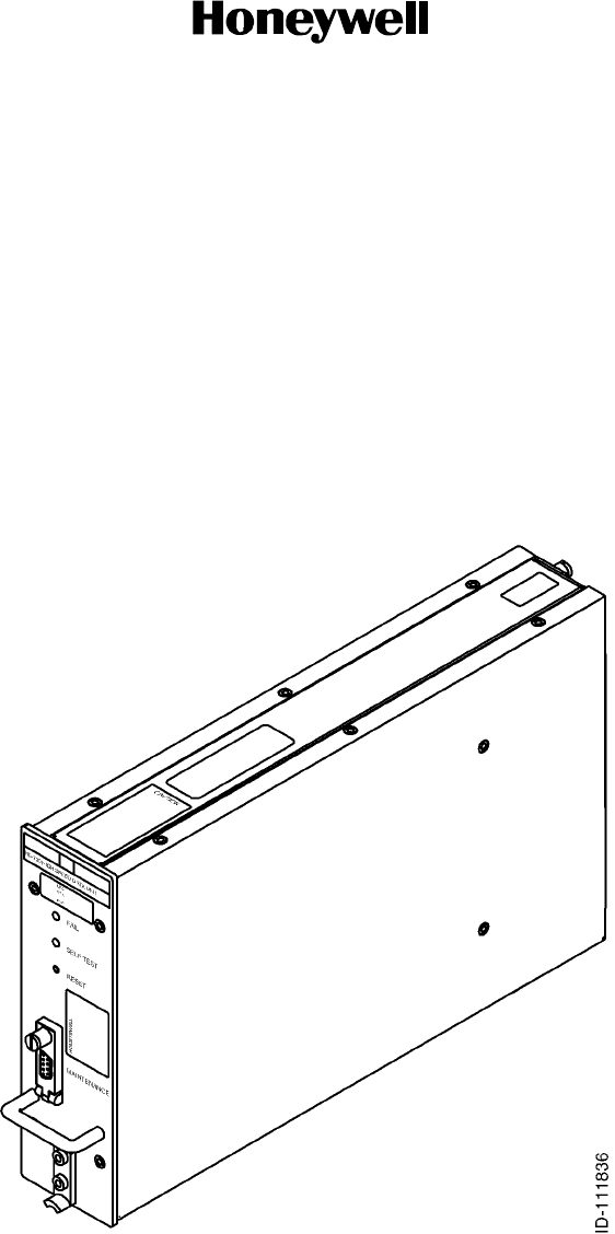
(1) The HSU is designed to perform reliably under field conditions and provide ease of
maintenance when required.
(2) The HSU is packaged as a 1/4 short ATR. The mechanical chassis is constructed of
aluminum alloy sheet metal. The HSU does not require external cooling air. The HSU
is shown in Figure 1-2.
(3) Table 1-6 gives the leading particulars for the HSU and Table 1-7 gives the DO--160D
categories that this equipment meets or exceeds.
Figure 1-2. HS--700 HSU

SYSTEM DESCRIPTION AND INSTALLATION MANUAL
HS--700 High Speed Data System
23--20--33
30 Aug 2002
Use or disclosure of information on this page is subject to the restrictions in the proprietary notice of this document.
Page 1--12
Table 1-6. HS--700 Leading Particulars
Characteristic Specification
Dimensions (maximum):
•Length ................................
•Width .................................
•Height ................................
12.99 in. (329.946 mm)
2.25 ±0.03 in. (57.150 ±0.762 mm)
7.62 in. (193.548 mm)
Weight (maximum) ....................... 4.63 lb (2.1 kg) nominal, 5.97 lb (2.7 kg) maximum
Power requirements (continuous operation):
•Nominal ............................... 28 V dc
•Maximum ............................. 32.2 V dc
•Minimum .............................. 20.5 V dc
Powerconsumption....................... 20 W maximum (eight ISDN phones connected)
Power hold--up ........................... 5 ms (fully operational), 200 ms (power save mode)
1.
Cooling requirements ..................... None
Connector X1 (front) ...................... D--sub 9 contact receptacle
Mating connector (X1) .................... Standard D--sub 9 contact plug
Connector X2 (rear) ...................... Radiall Part No. 616--697--202
Mating connector (X2) .................... Radiall Part No. 616--697--201
•20AWGcontacts ...................... Radiall Part No. 616--310
•16AWGcontacts ...................... Radiall Part No. 616--330
•Size 5 twinax contacts .................. Radiall Part No. 616--095--001
•Size5coaxcontacts.................... Radiall Part No. 616--021
Mounting ................................ Tray, ARINC 404A, 1/4 short ATR
Tuning range:
•RX ................................... 1525.0 to 1559.0 MHz
•TX ................................... 1626.5 to 1660.5 MHz
Doppler compensation .................... ±2.5 kHz (approximately ±360 m/s)
Rate of Doppler frequency change
(maximum) .............................. ±65 Hz/s (approximately 50°banking angle)
RF receive levels:
•M4 (134.4 kbps) ....................... --96 to --43 dBm per carrier
•Mini--M(3.0kbps) ...................... --109 to --50 dBm per carrier
2.

SYSTEM DESCRIPTION AND INSTALLATION MANUAL
HS--700 High Speed Data System
23--20--33
30 Aug 2002
Use or disclosure of information on this page is subject to the restrictions in the proprietary notice of this document.
Page 1--13
Table 1-6. HS--700 Leading Particulars (cont)
Characteristic Specification
RF transmit levels:
•Output power level (nominal) ............ +12 dBm
•Output power level range ................ -- 1 3 t o + 1 3 d B m
Channel spacing:
•High speed data M--4 channel (134.4 kbps) 40.0 kHz
•Mini--M transmit signalling (3.0 kbps) ...... 20.0 kHz
•Mini--M receive signalling (6.0 kbps) ...... 10.0 kHz
Channel grid spacing (all channel types) ..... 1.25 kHz
MPDS232 .............................. EIA/TIA--232, 115.2 kbps, asynchronous RFC 1549
high--level data link control (HDLC), configuration: data
circuit--terminating equipment (DCE) with hardware flow
control
MPDS 10BASE--T ........................ Ethernet 10BASE--T (10 Mbps)
ISDN:
•UDI .................................. 64 kbps
•Data .................................. 56 kbps
•Audio ................................. 64 kbps (3.1 kHz)
•Speech ............................... 64 kbps
Faxdatarate ............................ 14,400 bps V.17 (3.1 kHz audio)
SDUcontrolinterface ..................... 100 kbps high speed ARINC 429
Configuration and maintenance ............ Standard asynchronous serial EIA/TIA--232--E, 9.6 kbps
(115.2 kbps for software upload) via front panel CMT1
interface, configuration: DCE with software flow control,
XON, XOFF
Ambient temperature:
•Operational ............................ -- 2 0 °Cto+55°C
•Storage ............................... -- 5 5 °Cto+85°C
Altitude:
•Non--pressurized(CatF1) ............... 55,000 ft
•Pressurized(CatA1) ................... 15,000 ft
Relative humidity ......................... 95% non--condensing at +50 °C
Circuit breaker current capability ............ 20 W at 17.7 V dc
3.

SYSTEM DESCRIPTION AND INSTALLATION MANUAL
HS--700 High Speed Data System
23--20--33
30 Aug 2002
Use or disclosure of information on this page is subject to the restrictions in the proprietary notice of this document.
Page 1--14
Table 1-6. HS--700 Leading Particulars (cont)
Characteristic Specification
Power supply cable impedance requirement . Less than 225 milliohm (includes circuit breaker)
NOTES:
1. During the power save mode, there is a short interruption, but the connection/call is kept (no redial is necessary).
2. The HS--700 does not support mini--M services. The mini--M transmit and receive signals are only used for
signalling/controlling the Aero--M4 high speed data services.
3. Forexample,theKlixon2TCseriescircuitbreakerwitha4Acurrentrating,orequivalent, should be sufficient for
most installations.
Table 1-7. DO--160D Environmental Categories
Description Category
Temperature and Altitude A1F1
In--Flight Loss of Cooling X
Temperature Variation C
Humidity A
Shock B
Vibration S2B2
Explosion Proofness E
Waterproofness X
Fluids Susceptibility X
Sand and Dust X
Fungus Resistance X
Salt Spray X
Magnetic Effect A
Power Input A()B
Voltage Spike A
Audio Frequency Susceptibility A()B
Induced Signal Susceptibility Z
Radio Frequency (RF) Susceptibility RRR
Emission of RF Energy M
Lightning Indirect Effects A3E3
Lightning Direct Effects X
SYSTEM DESCRIPTION AND INSTALLATION MANUAL
HS--700 High Speed Data System
23--20--33
30 Aug 2002
Use or disclosure of information on this page is subject to the restrictions in the proprietary notice of this document.
Page 1--15
Table 1-7. DO--160D Environmental Categories (cont)
Description Category
Icing X
Electrostatic Discharge (ESD) A
(4) Table 1-8 gives a description of the HSU front panel lights and button.
Table 1-8. HSU Front Panel Description
LED/Button Description
FAIL LED The red FAIL LED continually illuminates when a failure has been detected
in the HSU which can degrade the system operation.
SELF TEST LED The green SELF TEST LED continually flashes during POST and PAST to
indicate that the self test is operating. The LED is extinguished when all
self tests have been completed.
RESET Button The HSU has a RESET button on the front panel for BITE purposes. If the
RESET button is pushed, the HSU first asks the SDU for permission to
perform the reset procedure. The RESET button can be activated at any
time. During the RF loop back part of the test procedure, the HPA and
DLNA are switched off by the SDU.
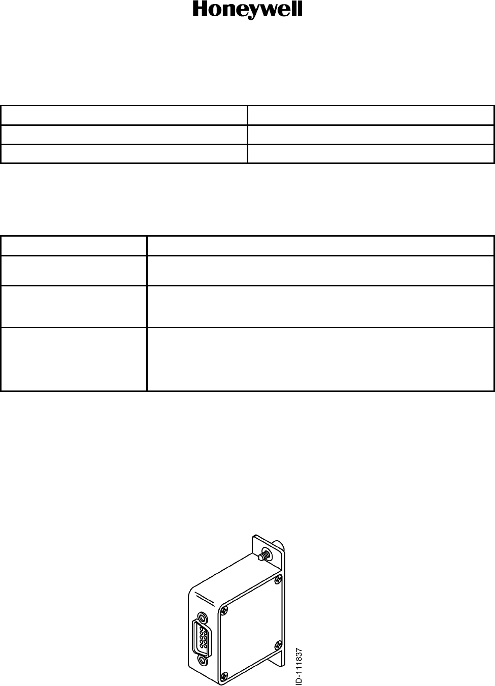
B. CDM
(1) The CDM is housed in a small box which fits into the slot on the rear panel of the
HSU. Figure 1-3 shows the CDM. The leading particulars for the CDM are given in
Table 1-9.
NOTE: When extracting the LRU from the aircraft’s mounting tray for maintenance,
detach the CDM from the rear of the removed LRU and install the CDM on
the replacement LRU.
Figure 1-3. CDM

SYSTEM DESCRIPTION AND INSTALLATION MANUAL
HS--700 High Speed Data System
23--20--33
30 Aug 2002
Use or disclosure of information on this page is subject to the restrictions in the proprietary notice of this document.
Page 1--16
Table 1-9. CDM Leading Particulars
Characteristic Specification
Dimensions (maximum):
•Length ................................
•Width .................................
•Height (excluding fasteners) .............
1.79 ±0.02 in. (45.5 ±0.05 mm)
0.79 ±0.02 in. (20.0 ±0.05 mm)
2.68 ±0.02 in. (68.0 ±0.05 mm)
Weight (maximum) ....................... .022 lb (0.1 kg)
Power requirement ....................... +3.0 to +3.5 V dc
Powerconsumption....................... 5mA
Power hold--up ........................... Full power hold--up provided by the HSU
Memory capacity ......................... 32 kbyte
Write sessions ........................... 100,000 minimum
Ambient temperature:
•Operational ............................ -- 2 0 °Cto+55°C
•Storage ............................... -- 5 5 °Cto+85°C
Altitude:
•Non--pressurized(CatF1) ............... 55,000 ft
•Pressurized(CatA1) ................... 15,000 ft
Relative humidity ......................... 95% non--condensing at +50 °C
SYSTEM DESCRIPTION AND INSTALLATION MANUAL
HS--700 High Speed Data System
23--20--33
30 Aug 2002
Use or disclosure of information on this page is subject to the restrictions in the proprietary notice of this document.
Page 1--17
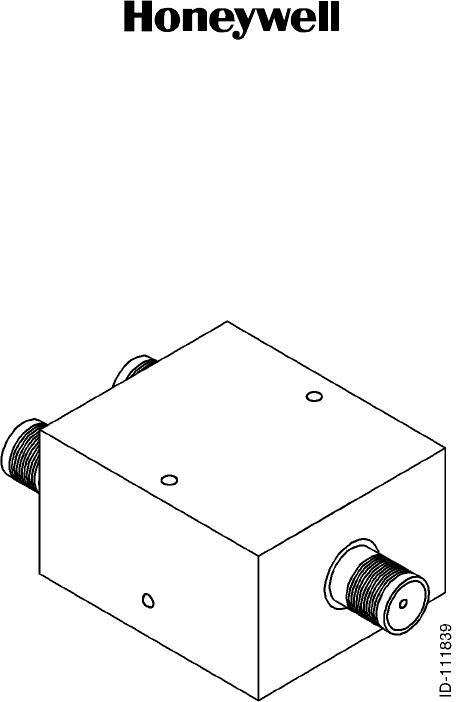
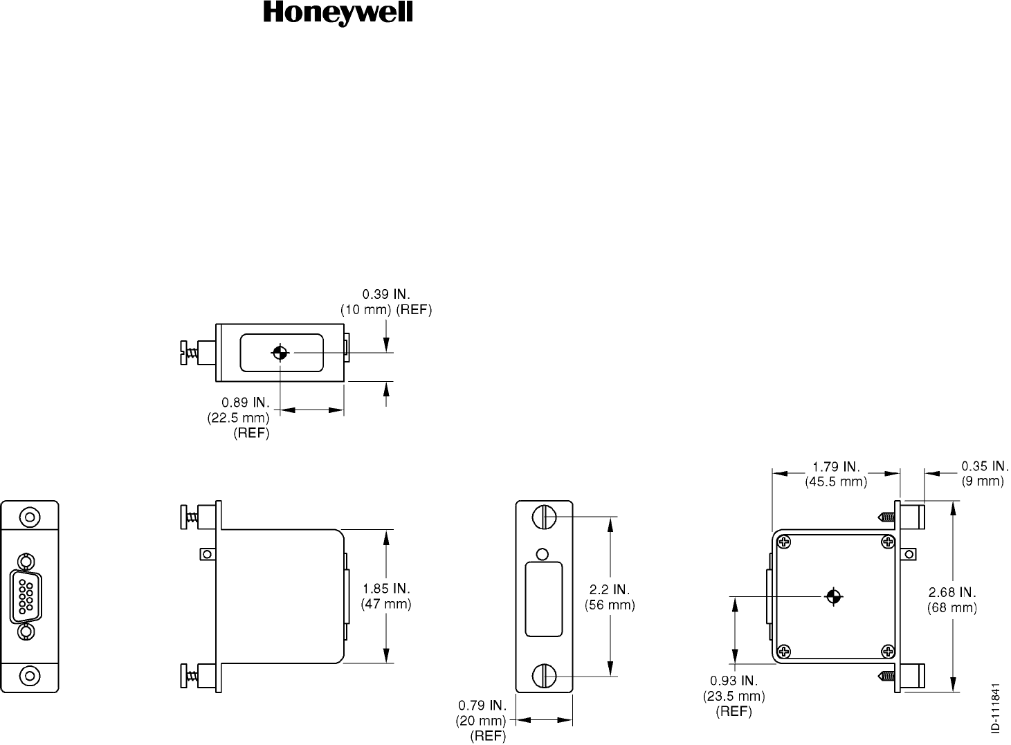
C. RF Splitter/Combiner
(1) One RF splitter/combiner divides the signal received from the DLNA which is then
sent to the SDU and HSU; the other RF splitter/combiner combines the transmit
outputs of the SDU and HSU to drive the HPA. Each unit weighs 2.5 oz. (70.87
grams). Figure 1-4 shows the RF splitter/combiner.
Figure 1-4. RF Splitter/Combiner
D. HSU Mounting Tray
(1) The HS--700 HSU ARINC 404A connector, contacts, and mounting trays can be
purchased from ECS or EMTEQ. The addresses for ECS and EMTEQ are as follows:
Electronic Cable Specialists
5300 W. Franklin Drive
Franklin, WI 53132
U.S.A.
Telephone: (414) 421--5300
Fax: (414) 421--5301
EMTEQ
S84 W. 18693 Enterprise Drive
Muskego, WI 53150
U.S.A.
Telephone: (262) 679--6170 / 1--888--679--6170

SYSTEM DESCRIPTION AND INSTALLATION MANUAL
HS--700 High Speed Data System
23--20--33
30 Aug 2002
Use or disclosure of information on this page is subject to the restrictions in the proprietary notice of this document.
Page 1--18
(2) Table 1-10 gives a list of HSU mounting trays available through ECS. Contact
EMTEQ for a list of HSU mounting trays available.
Table 1-10. HSU Mounting Trays
ECS Part No. Description Voltage
4130 1/4 ATR Tray Assembly Short/Short with DPX2 Cutout 28 V dc

SYSTEM DESCRIPTION AND INSTALLATION MANUAL
HS--700 High Speed Data System
23--20--33
30 Aug 2002
Use or disclosure of information on this page is subject to the restrictions in the proprietary notice of this document.
Page 2--1
SECTION 2
MECHANICAL INSTALLATION
1. Overview
A. General
(1) This section contains information on how and where to mount the HSU, CDM,
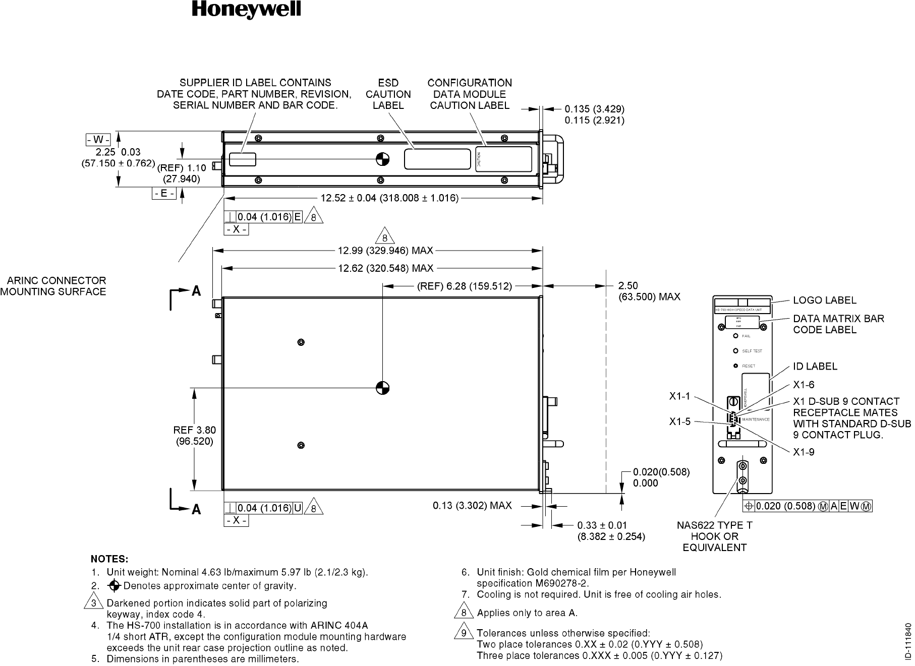
combiner, and splitter. Figure 2-1 shows the HSU dimensions. Figure 2-2 shows
mounting tray dimensions. Figure 2-3 shows the physical attributes of the CDM.
Figure 2-4 shows the dimensions and mounting hole dimensions of the RF
splitter/combiner.
B. Equipment and Materials
(1) See the applicable outline and installation diagram in this section for mounting
information.
2. Mechanical Installation Design
A. HS--700 HSU Provisions
(1) Mechanical installation data for the HS--700 HSU is shown in Figure 2-1. The HSU is
mounted in an ARINC 404A 1/4 ATR short , 2MCU chassis with one hold--down
hook. It can be installed inside the pressurized area, or outside (within the limits of
DO--160D specifications). It is important that the HSU is installed in a location where
its operational temperature specifications are met. The HSU is approved for
installation on jet engine aircraft, but not turboprops or helicopters. No special cooling
is required, but the airflow must not be blocked.
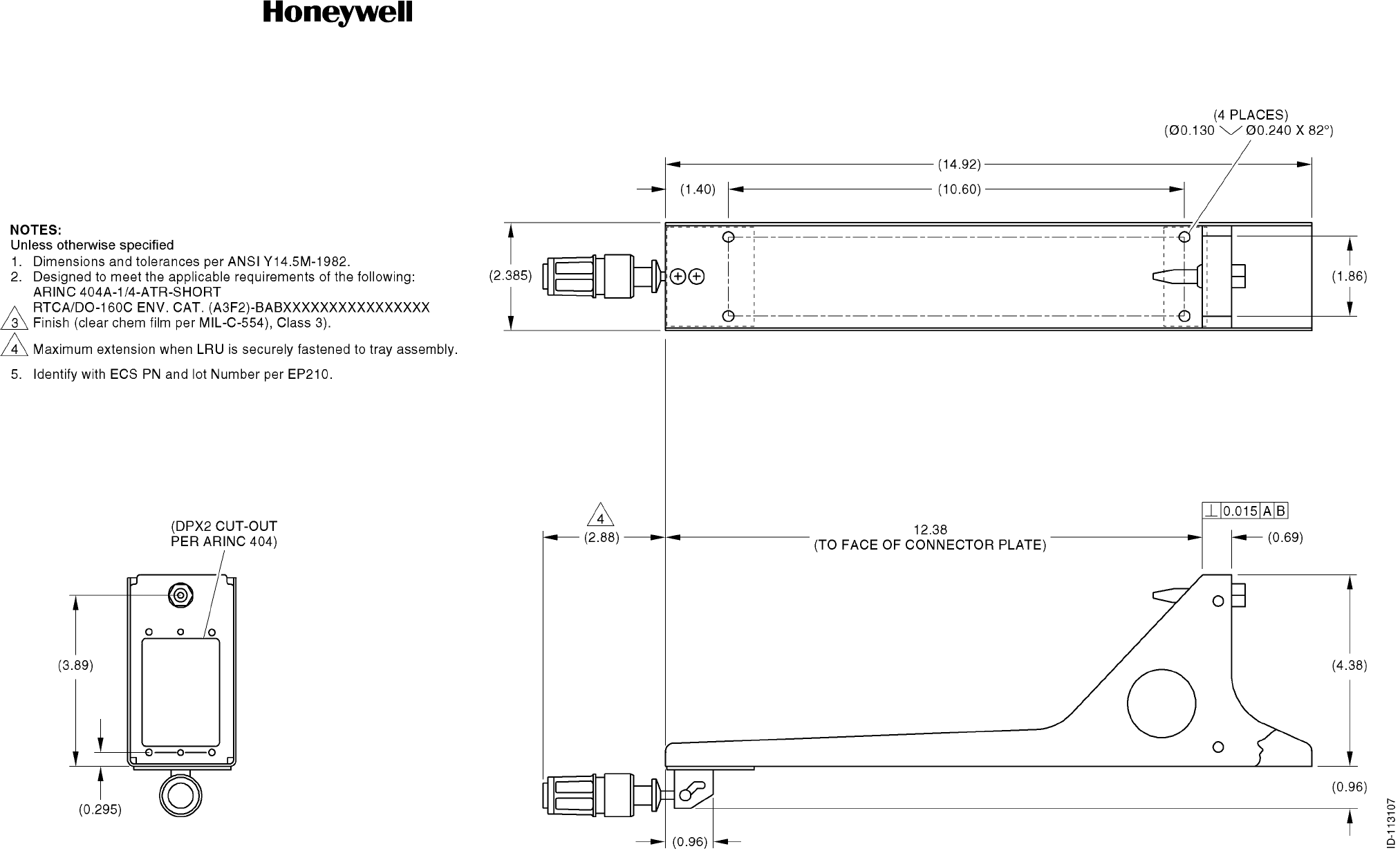
(2) The location of the mounting tray should allow the interface cabling to other units to
be as short as possible. The location must give protection against rain, condensation,
solvents, and hydraulic fluid. The mounting tray must be electrically bonded to the
aircraft frame by a low resistance path of less than 0.1 ohm. Mechanical installation
data for the mounting tray is shown in Figure 2-2.
B. CDM Provisions
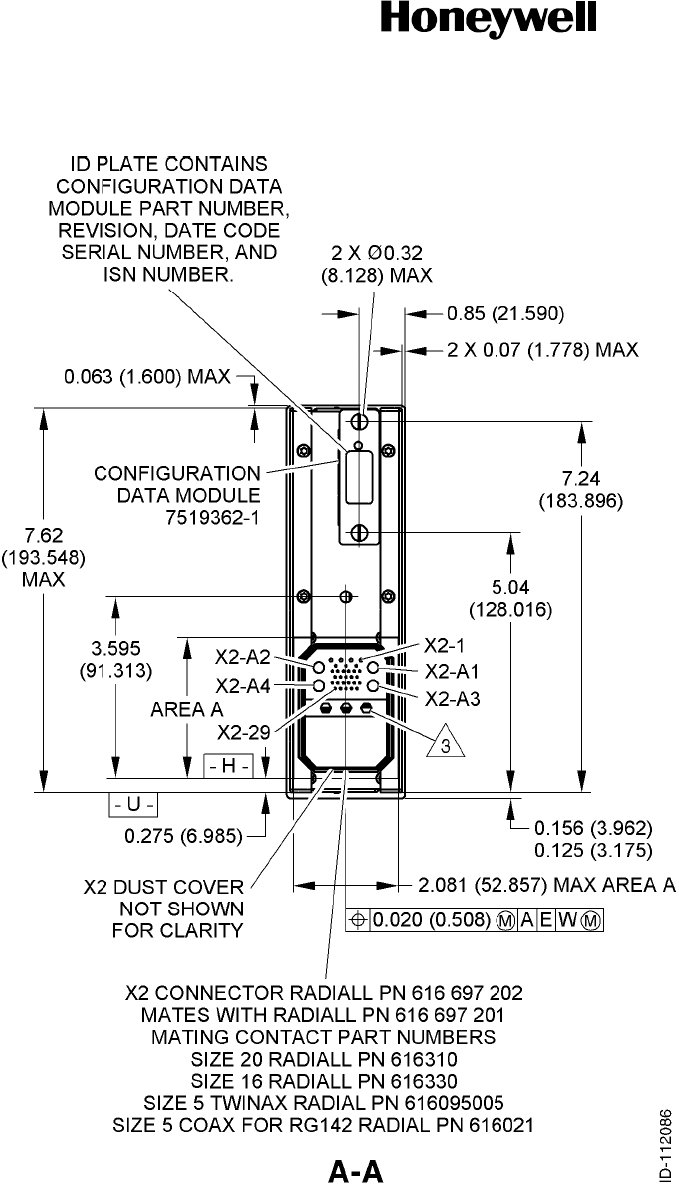
(1) Mechanical installation data for the CDM is shown in Figure 2-3. The CDM is
designed for mounting into the slot in the HSU rear panel and acts as an integrated
part of the HSU. The CDM has the same installation requirements as the HSU.
(2) AstudontheCDMcanbeusedtoattachatetherbetweentheCDMandthe
mounting tray to make sure that the CDM stays with the aircraft in case the HSU
must be replaced.
C. RF Splitter/Combiner Provisions
(1) Mechanical installation data for the splitter/combiner is shown in Figure 2-4.

SYSTEM DESCRIPTION AND INSTALLATION MANUAL
HS--700 High Speed Data System
23--20--33
30 Aug 2002
Use or disclosure of information on this page is subject to the restrictions in the proprietary notice of this document.
Page 2--2
Blank Page
SYSTEM DESCRIPTION AND INSTALLATION MANUAL
HS--700 High Speed Data System
23--20--33
30 Aug 2002
Use or disclosure of information on this page is subject to the restrictions in the proprietary notice of this document.
Page 2--3/(2--4 blank)
Figure 2-1 (Sheet 1). HSU Outline and Installation Diagram
SYSTEM DESCRIPTION AND INSTALLATION MANUAL
HS--700 High Speed Data System
23--20--33
30 Aug 2002
Use or disclosure of information on this page is subject to the restrictions in the proprietary notice of this document.
Page 2--5/(2--6 blank)
Figure 2-1 (Sheet 2). HSU Outline and Installation Diagram
SYSTEM DESCRIPTION AND INSTALLATION MANUAL
HS--700 High Speed Data System
23--20--33
30 Aug 2002
Use or disclosure of information on this page is subject to the restrictions in the proprietary notice of this document.
Page 2--7/(2--8 blank)
Figure 2-2. Mounting Tray Outline and Installation Diagram
SYSTEM DESCRIPTION AND INSTALLATION MANUAL
HS--700 High Speed Data System
23--20--33
30 Aug 2002
Use or disclosure of information on this page is subject to the restrictions in the proprietary notice of this document.
Page 2--9/(2--10 blank)
Figure 2-3. CDM Outline and Installation Diagram
SYSTEM DESCRIPTION AND INSTALLATION MANUAL
HS--700 High Speed Data System
23--20--33
30 Aug 2002
Use or disclosure of information on this page is subject to the restrictions in the proprietary notice of this document.
Page 2--11
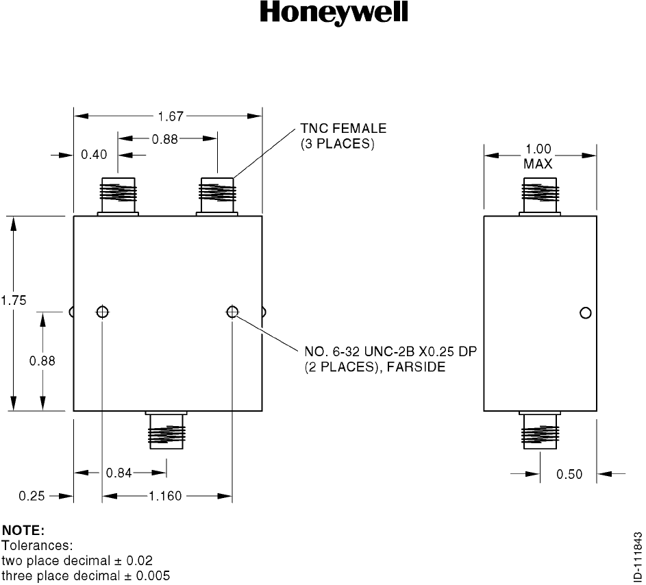
Figure 2-4. RF Splitter/Combiner Outline Diagram

SYSTEM DESCRIPTION AND INSTALLATION MANUAL
HS--700 High Speed Data System
23--20--33
30 Aug 2002
Use or disclosure of information on this page is subject to the restrictions in the proprietary notice of this document.
Page 2--12
Blank Page

SYSTEM DESCRIPTION AND INSTALLATION MANUAL
HS--700 High Speed Data System
23--20--33
30 Aug 2002
Use or disclosure of information on this page is subject to the restrictions in the proprietary notice of this document.
Page 3--1
SECTION 3
ELECTRICAL INSTALLATION
1. Overview
A. General
(1) This section gives electrical installation procedures, power distribution, and
interconnect information for the HSU, combiner, and splitter.
(2) Procedures for proper shield, power, and signal grounding are also provided in this
section. In addition, procedures for the various buses are included.
B. Equipment and Materials
(1) See leading particulars table for a list of mating connectors required to do the
electrical installation.
2. Electrical Installation Procedure
A. General
(1) The information necessary to provide the electrical interconnects is contained in the
following paragraphs.
B. Power Requirements
(1) The aircraft dc power supply must be 28 V dc (nominal). The normal minimum and
maximum voltages permitted are 20.5 and 32.2 V dc respectively.
(2) Power supply to the HSU -- The voltage level of the power supplied to the HSU is
important in this installation. The potential is the difference between the power pins
and power ground pins at the line replaceable unit (LRU). Excessive voltage drops in
the power wire(s) and power ground wire(s) cause one or more of the following
conditions:
•The LRU draws additional current from the aircraft supply system.
•The voltage drop can become large enough that the LRU oscillates on and off at
low line. This oscillation can damage the LRU.
(3) The HSU is supplied from the 28 V dc aircraft power system through a separate
circuit breaker. It is essential to keep the impedance of the power supply cables
below the limits specified in Table 1-6. The HSU also provides the power supply
voltages to the CDM.
(4) The recommended maximum total combined voltage drop (voltage drop of the power
wire[s] plus voltage drop of the power ground wire[s]) low line input is 1.0 V. Voltage
drop is a function of current and resistance (resistance in this case is a function of
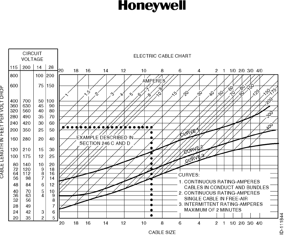
wire gauge and wire length). See Figure 3-1 for determining proper wire gauge for a
round trip length of LRU power and power ground wires.
SYSTEM DESCRIPTION AND INSTALLATION MANUAL
HS--700 High Speed Data System
23--20--33
30 Aug 2002
Use or disclosure of information on this page is subject to the restrictions in the proprietary notice of this document.
Page 3--2
Figure 3-1. Electric Cable Chart
C. Ground Requirements
(1) General
(a) Proper grounding is a key factor in ensuring proper system operation under
normal conditions, high intensity radiated electromagnetic frequencies (HIRF),
and lightning environments. You must obey this section to satisfy these
requirements.
NOTE: HIRF and lightning requirements dictate that the shielded wires meet
the requirements of paragraph 2.C.(3). Installation of this system into
aircraft manufactured prior to the FAA requirements adheres to these
practices whenever feasible.
(2) Chassis Grounding
(a) All rack mount/remote mount units are electrically bonded to the airframe. This is
done by making sure the mating surfaces between the LRU mounting tray (or
LRU mounting feet if a tray is not used) provide a low impedance (< 0.1 Ω)
electrical path.
SYSTEM DESCRIPTION AND INSTALLATION MANUAL
HS--700 High Speed Data System
23--20--33
30 Aug 2002
Use or disclosure of information on this page is subject to the restrictions in the proprietary notice of this document.
Page 3--3
(b) The mating surfaces must be free of all paint and other non--conductive
elements and are burnished to ensure a good bond. If the aircraft mating surface
is not conductive, a bonding strap of a least 1/4--inch wide (preferably 1/2--inch
wide) tin coated copper braid can be used between the LRU mounting tray (or
LRU itself if a tray is not used) and the nearest airframe grounding point.
(3) Shield Grounds
(a) The shield wires in the HSU have the shield grounded at both ends. This is
called multi--point grounding and is specified to minimize the adverse effects of
HIRF and lightning.
(b) The shield must not be connected to any LRU or bulkhead connector pin.
(c) Examples of multi--point shield grounding methods are shown in Figure 3-2 and
Figure 3-3. The shield grounding method for rack mount units is detailed in
Figure 3-4. This is the preferred shield grounding method for the HSU rack
mount unit.
Figure 3-2. Example 1, Multi--point Shield Ground
Figure 3-3. Example 2, Multi--point Shield Ground
SYSTEM DESCRIPTION AND INSTALLATION MANUAL
HS--700 High Speed Data System
23--20--33
30 Aug 2002
Use or disclosure of information on this page is subject to the restrictions in the proprietary notice of this document.
Page 3--4
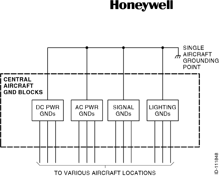
Figure 3-4. Shield Grounding Example for Rack Mount Connectors
(4) Power/Signal Grounds
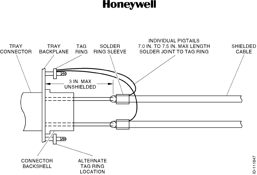
(a) The length of exposed unshielded cable and the length of the drain leads is
critical for proper operation and EMC compliance. Figure 3-5 shows the proper
aircraft grounding method. It is critical that the ground pigtails be individually
connected to the tag ring(s). If the are daisy--chained, there will be EMC
compliance issues. Coaxial cables must have a continuous shield from the cable
into the tray connector. Do not put pigtails coaxial cables.
NOTE: It is very important this grounding technique be adhered to. Do not tie
the various ground wires to multiple aircraft frame points and depend on
the aircraft structure to supply a low impedance path for the individual
grounds. Only chassis grounds and shield grounds are grounded at
multiple points in the aircraft.
SYSTEM DESCRIPTION AND INSTALLATION MANUAL
HS--700 High Speed Data System
23--20--33
30 Aug 2002
Use or disclosure of information on this page is subject to the restrictions in the proprietary notice of this document.
Page 3--5
Figure 3-5. Aircraft Grounding
(b) Because signal grounds are low currents, multiple signal grounds can be
connected to remote aircraft terminal blocks other than the central grounding
blocks as long as these remote terminal blocks are isolated from ground. The
various remote signal ground blocks must all be grounded only at the aircraft
central grounding point. If 10 signal grounds are connected to a remote terminal
block, a minimum of one grounding wire must be run from this terminal block to
the aircraft central grounding point.
SYSTEM DESCRIPTION AND INSTALLATION MANUAL
HS--700 High Speed Data System
23--20--33
30 Aug 2002
Use or disclosure of information on this page is subject to the restrictions in the proprietary notice of this document.
Page 3--6
3. Electrical Installation
A. HSU
(1) General
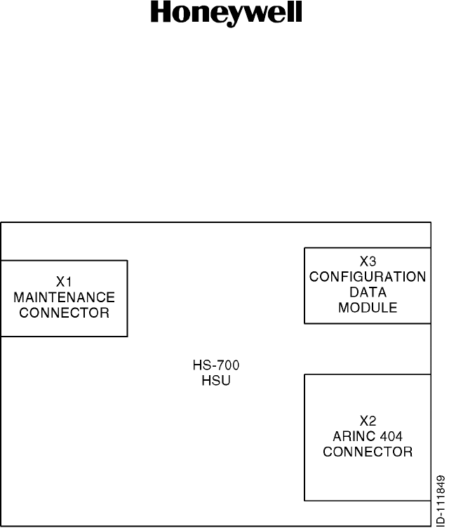
(a) The HSU interface block diagram is shown in Figure 3-6.
Figure 3-6. HSU Interface Block Diagram
(2) HSU X1 Connector
(a) The HSU front panel X1 connector is an interface to a PC for maintenance
purposes. The X1 connector is a 9--pole female sub--D filter connector. The HSU
X1 connector layout is shown in Figure 3-7. Table 3-1 gives the pin assignments
of the X1 connector.
(b) The HSU has two CMT interfaces, one on the X1 connector (CMT1) and one on
the X2 connector (CMT2). Both interfaces support EIA/TIA--232--E standard and
canalsobeusedasaprinterinterface.OnlytheCMT1ontheX1connectorcan
be used for software uploading. The interfaces are configured as DCE on the
HSU.
(c) The CMT1 interface (pins 2, 3, and 5) has a Baud rate of 9,600 bps or 115.2
kbps for software uploading. There are eight data bits and one stop bit with no
parity.
(d) The HSU X1 connector contains an input pin (pin 4) to disable the X2 rear
connector CMT2 interface. If the rear connector CMT2 interface is connected to
a terminal, it is diabled when using the front connector CMT1 since both CMTs
share the same internal serial I/O port.
(e) The rear connector CMT2 interface is disabled by connecting X1 connector pin 4
to--12Vdc.Thisisdonebymountingajumperfrompin4topin6intheserial
cable plug. If a fully populated RS--232 serial cable is used, no jumper is needed.

SYSTEM DESCRIPTION AND INSTALLATION MANUAL
HS--700 High Speed Data System
23--20--33
30 Aug 2002
Use or disclosure of information on this page is subject to the restrictions in the proprietary notice of this document.
Page 3--7
Figure 3-7. HSU Maintenance Connector (X1) Pin Layout
Table 3-1. HSU X1 Connector Pin Assignments
Pin Signal Name/Description
1Not Used
2CMT1 RXD Output (EIA/TIA--232--E)
3CMT1 TXD Input (EIA/TIA--232--E)
4CMT2 Interface Disable Input
5CMT1 GND (EIA/TIA--232--E)
6CMT1 --12VDC (to pull down pin 4)
7Not Used
8Not Used
9Not Used
(3) HSU X2 Connector
(a) The HSU rear panel X2 connector is an interface to aircraft and SATCOM
interconnections. The X2 connector is an ARINC 404 shell size 2 receptacle
connector. The layout of the HSU X2 connector is shown in Figure 3-8. Table 3-2
gives the pin assignments of the X2 connector.
(b) The HSU disable input is used by the SDU to reset and inhibit the transmitter
output signal from the HSU. The ARINC 429 interface is used by the SDU to
control the HSU. The HSU operates as a slave to the SDU. The interface is a
100 kbps high speed ARINC 429 receive and transmit data bus to/from the SDU.
The HSU transmits and receives simultaneously on the two ARINC 429
channels.
(c) The CMT2 interface (pins 5, 6, and 7) has a Baud rate of 9,600 bps fixed. There
are eight data bits and one stop bit with no parity.
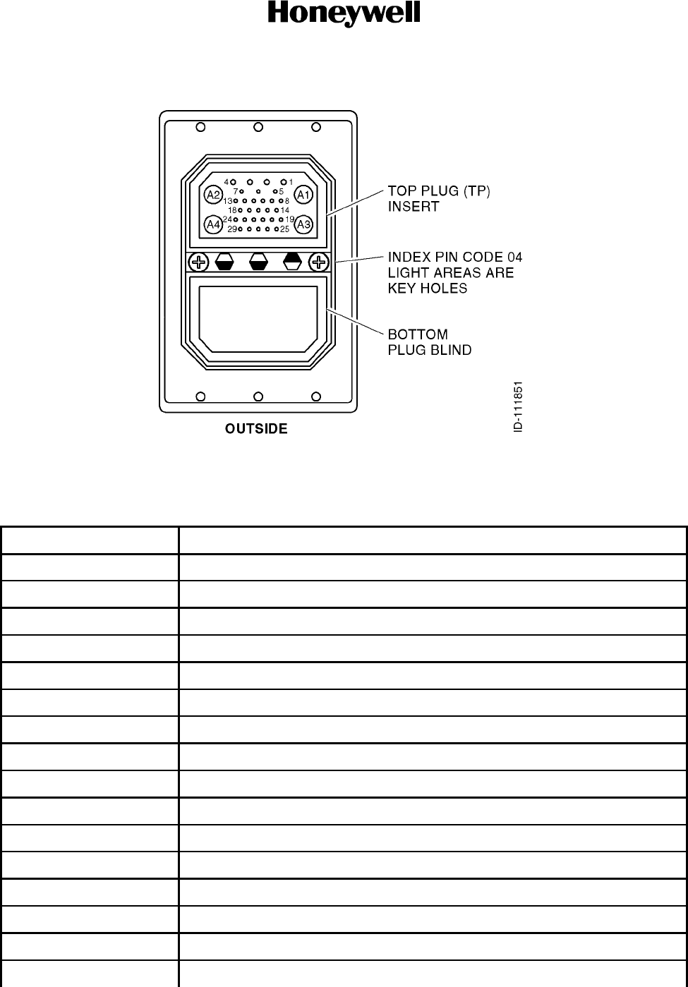
SYSTEM DESCRIPTION AND INSTALLATION MANUAL
HS--700 High Speed Data System
23--20--33
30 Aug 2002
Use or disclosure of information on this page is subject to the restrictions in the proprietary notice of this document.
Page 3--8
Figure 3-8. HSU ARINC 404 Connector (X2) Pin Layout
Table 3-2. HSU X2 Connector Pin Assignments
Pin Signal Name/Description
TP A1 RF RX Input from DLNA/Splitter
TP A2 RF TX Output to HPA/Combiner
TP A3 10Base--T RX Output to User (RJ--45 pins 3 and 6)
TP A4 10Base--T TX Input from User (RJ--45 pins 1 and 2)
TP1 +28 V dc Ground Power
TP2 GND (Ground Power Return)
TP3 Chassis Ground
TP4 Not Used
TP5 CMT2 GND (EIA/TIA--232--E)
TP6 CMT2 TXD Input (EIA/TIA--232--E)
TP7 CMT2 RXD Output (EIA/TIA--232--E)
TP8 HSU Disable Discrete Input
TP9 ATE #1 Discrete Input
TP10 ATE #2 Discrete Input
TP11 MPDS TXD Input (EIA/TIA--232--E) from User (DB25--2/DE9--3)
TP12 MPDS RXD Output (EIA/TIA--232--E) to User (DB25--3/DE9--2)

SYSTEM DESCRIPTION AND INSTALLATION MANUAL
HS--700 High Speed Data System
23--20--33
30 Aug 2002
Use or disclosure of information on this page is subject to the restrictions in the proprietary notice of this document.
Page 3--9
Table 3-2. HSU X2 Connector Pin Assignments (cont)
Pin Signal Name/Description
TP13 MPDS RTS Input (EIA/TIA--232--E) from User (DB25--4/DE9--7)
TP14 MPDS CTS Output (EIA/TIA--232--E) to User (DB25--5/DE9--8)
TP15 MPDS DTR Input (EIA/TIA--232--E) from User (DB25--20/DE9--4)
TP16 MPDS DCD Output (EIA/TIA--232--E) to User (DB25--8/DE9--1)
TP17 MPDS DSR Output (EIA/TIA--232--E) to User (DB25--6/DE9--6)
TP18 MPDS GND (EIA/TIA--232--E) (DB25--7/DE9--5)
TP19 Data Bus Output to SDU (ARINC 429--A)
TP20 Data Bus Output to SDU (ARINC 429--B)
TP21 Data Bus Input from SDU (ARINC 429--A)
TP22 Data Bus Input from SDU (ARINC 429--B)
TP23 ISDN TxP (c) Input + (Plus) from User (RJ--45 pin 3)
TP24 ISDN RxP (d) Output + (Plus) to User (RJ--45 pin 4)
TP25 ISDN RxN (e) Output -- (Minus) to User (RJ--45 pin 5)
TP26 ISDN TxN (f) Input -- (Minus) from User (RJ--45 pin 6)
TP27 HSU Failure Discrete Output (Lamp Type)
TP28 Service Available Discrete Output (Lamp Type)
TP29 Discrete Output Spare 2 (Lamp Type)
(4) HSU X3 Connector
(a) The HSU rear panel X3 CDM connector is an interface to the CDM. The X3
connector is a 9--pole female sub--D connector. The layout of the HSU X3
connector is shown in Figure 3-9. Table 3-3 gives the pin assignments of the X3
connector.
(b) The CDM consists of a write protected memory area and a non--write protected
memory area. The write protected area contains the ISN number and the
forward/return IDs which can only be altered by the manufacturer. The non--write
protected area contains the system configuration and installation specific data.
The contents of the non--write protected area can be altered or accessed by use
of a software password. The communication protocol between the HSU and the
CDM follows a synchronous serial protocol.
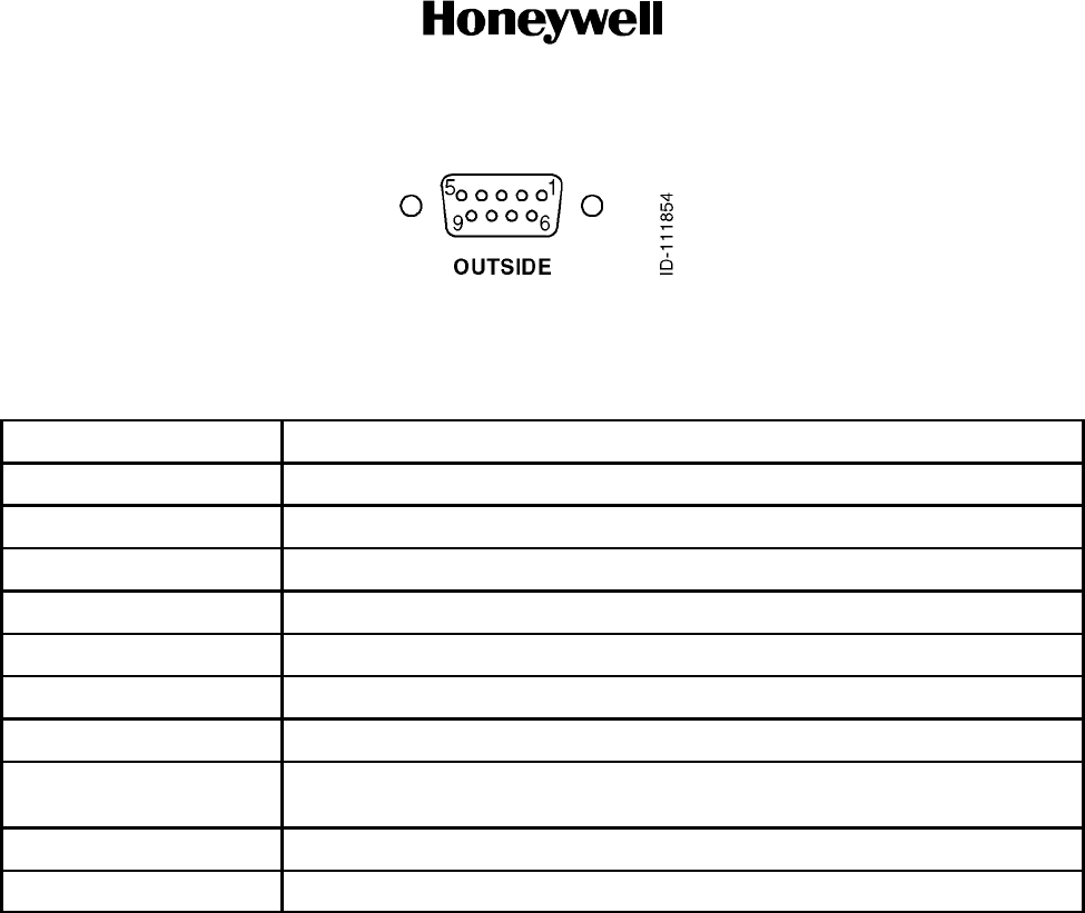
SYSTEM DESCRIPTION AND INSTALLATION MANUAL
HS--700 High Speed Data System
23--20--33
30 Aug 2002
Use or disclosure of information on this page is subject to the restrictions in the proprietary notice of this document.
Page 3--10
Figure 3-9. HSU CDM Connector (X3) Pin Layout
Table 3-3. HSU X3 Connector Pin Assignments
Pin Signal Name/Description
1CS -- Chip Select Signal to the CDM (Active Low)
2SO -- Serial Output Data from the CDM
3WP -- Write Protect Signal to the CDM (Active Low)
4NC -- Not Connected
5SI -- Serial Input Data to the CDM
6SCK -- Serial Clock to the CDM (2 MHz maximum)
7ADR0 -- Address output to the CDM (5 V/10 mA maximum)
8ADR1/ ID Input -- Output: 3 V Levels (Tri--state), Input: 3 V or 5 V Levels and
10 Kohm pull down resistor
9VCC -- Power Supply Voltage to the CDM (3.3 V ±0.15 V, 5 mA maximum)
Shield GND -- Sheild must be connected internally to ground
B. CDM
(1) The CDM is connected to the X1 connector of the HSU. Refer to paragraph 3.A.(4) in
this section for electrical installation information for the HSU X1 connector.
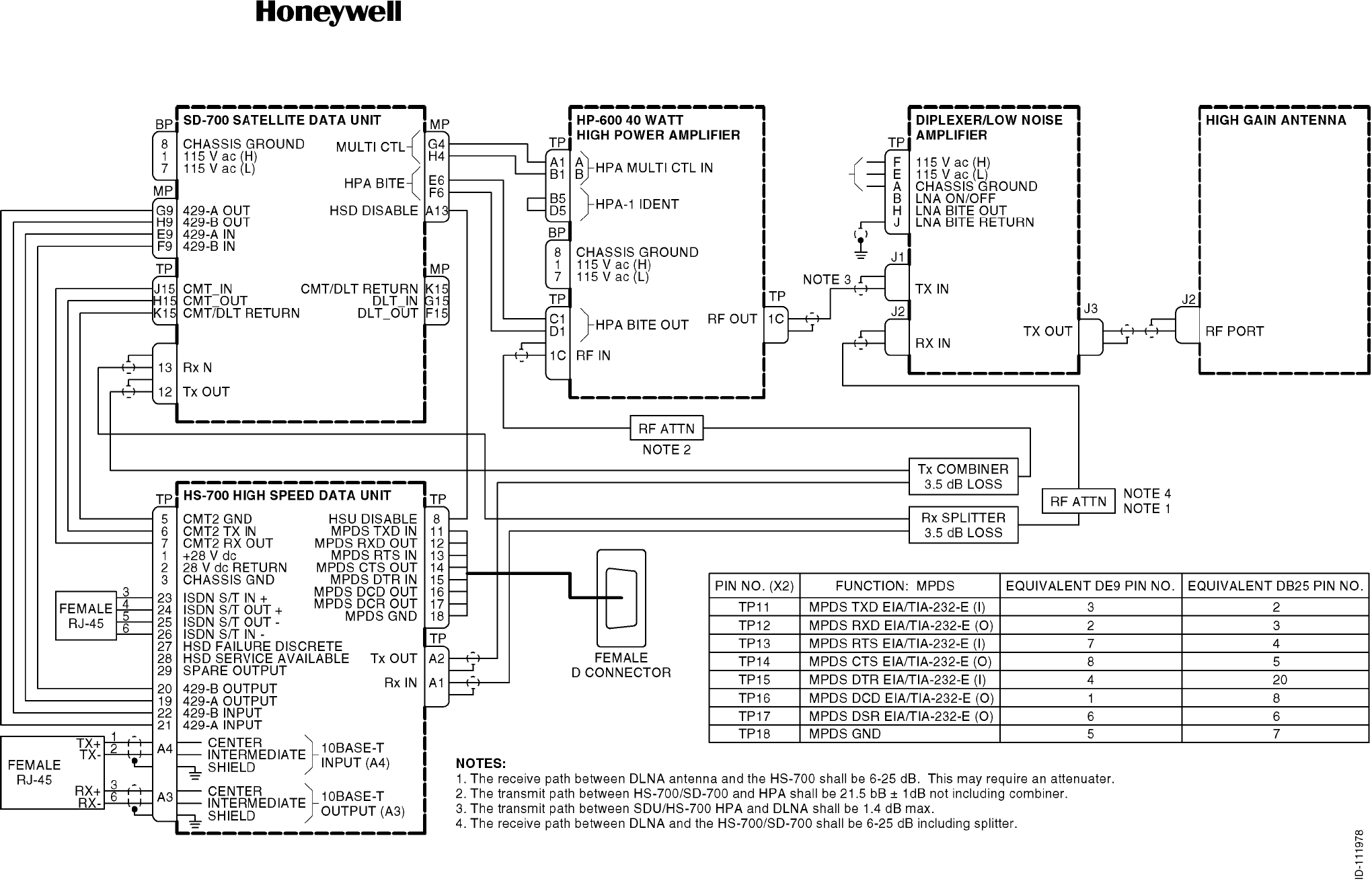
SYSTEM DESCRIPTION AND INSTALLATION MANUAL
HS--700 High Speed Data System
23--20--33
30 Aug 2002
Use or disclosure of information on this page is subject to the restrictions in the proprietary notice of this document.
Page 3--11/(3--12 blank)
Figure 3-10. HS--700 High Speed Data System Interconnect Diagram

SYSTEM DESCRIPTION AND INSTALLATION MANUAL
HS--700 High Speed Data System
23--20--33
30 Aug 2002
Use or disclosure of information on this page is subject to the restrictions in the proprietary notice of this document.
Page 4--1
SECTION 4
INSTALLATION CHECK
1. Overview
A. General
(1) TBD.

SYSTEM DESCRIPTION AND INSTALLATION MANUAL
HS--700 High Speed Data System
23--20--33
30 Aug 2002
Use or disclosure of information on this page is subject to the restrictions in the proprietary notice of this document.
Page 4--2
Blank Page

SYSTEM DESCRIPTION AND INSTALLATION MANUAL
HS--700 High Speed Data System
23--20--33
30 Aug 2002
Use or disclosure of information on this page is subject to the restrictions in the proprietary notice of this document.
Page 5--1
SECTION 5
ADJUSTMENT/TEST
1. Overview
A. General
(1) To be supplied.

SYSTEM DESCRIPTION AND INSTALLATION MANUAL
HS--700 High Speed Data System
23--20--33
30 Aug 2002
Use or disclosure of information on this page is subject to the restrictions in the proprietary notice of this document.
Page 5--2
Blank Page

SYSTEM DESCRIPTION AND INSTALLATION MANUAL
HS--700 High Speed Data System
23--20--33
30 Aug 2002
Use or disclosure of information on this page is subject to the restrictions in the proprietary notice of this document.
Page 6--1
SECTION 6
FAULT ISOLATION
1. Overview
A. General
(1) To be supplied.

SYSTEM DESCRIPTION AND INSTALLATION MANUAL
HS--700 High Speed Data System
23--20--33
30 Aug 2002
Use or disclosure of information on this page is subject to the restrictions in the proprietary notice of this document.
Page 6--2
Blank Page

SYSTEM DESCRIPTION AND INSTALLATION MANUAL
HS--700 High Speed Data System
23--20--33
30 Aug 2002
Use or disclosure of information on this page is subject to the restrictions in the proprietary notice of this document.
Page 7--1
SECTION 7
MAINTENANCE PRACTICES
1. Overview
A. General
(1) This section provides instructions for removing, reinstalling, and adjusting the HSU,
CDM, combiner, and/or splitter that has been previously installed by the aircraft
manufacturer or completion center. Adjustment information is called out as required.
CAUTION: SHOULD ANY INSTALLATION CRITICAL CASES ARISE WITH THE
REINSTALLATION OF ANY UNIT, YOU MUST COMPLY 100 PERCENT
WITH THE INSTRUCTION.
CAUTION: TO PREVENT DAMAGE TO EQUIPMENT, TURN AIRCRAFT POWER OFF
WHEN REMOVING OR INSTALLING LRUS.
B. Equipment and Materials
(1) No additional special equipment or materials, other than those commonly used in the
shop, are required to install the units in existing trays and clamps, and adjust the
system. Do not over tighten mounting screws. Where torque values are not given, it
is acceptable to finger tighten the mounting screws.
2. Procedure for the HS--700 HSU
A. Removal and Reinstallation Procedures
(1) Remove the HSU.
(a) Remove power from the HSU and the interfacing subsystems (such as
SATCOM). Circuit breakers for the systems are typically located on the flight
deck.
(b) Loosen the mounting tray holddown clamp by rotating in a counterclockwise
direction.
(c) Slowly pull forward on the unit handle to separate the unit and tray connectors
and slide the unit out of the tray, lifting slightly to clear the holddown clamps.
(d) Remove the CDM. Refer to paragraph 3. in this section.
(e) Place electrostatic protective covers on the HSU connectors to protect the pins
from damage.
(f) Place the HSU in a protective static--resistant bag and protective carrying case.

SYSTEM DESCRIPTION AND INSTALLATION MANUAL
HS--700 High Speed Data System
23--20--33
30 Aug 2002
Use or disclosure of information on this page is subject to the restrictions in the proprietary notice of this document.
Page 7--2
(2) Reinstall the HSU.
(a) Remove the HSU from the protective carrying case and protective
static--resistant bag.
(b) Remove the electrostatic protective covers from the HSU rear connector.
(c) Install the CDM. Refer to paragraph 3. in this section.
(d) Slide the unit into the mounting tray.
CAUTION: WHEN PLACING THE UNIT ON THE MOUNTING TRAY, DO NOT
FORCE FIT. IF MATING IS DIFFICULT, REMOVE THE UNIT AND
CHECK FOR CONNECTOR PINS THAT CAN BE BENT OR OUT OF
ALIGNMENT. ALSO VISUALLY CHECK THE ALIGNMENT OF THE
RECEPTACLE ON THE MOUNTING TRAY.
(e) Gently slide the unit backwards until its connectors are fully engaged with the
mating connectors of the mounting tray.
(f) Put the holddown clamps in place and tighten the knobs in a clockwise direction
until the proper torque is applied (clutch engages).
(g) Reapply power to the HSU and its interfacing equipment.
NOTE: Upon applying primary power, the HSU will automatically power up and
start a POST.
B. Adjustment Procedures
(1) Not applicable.
C. Repair Procedures
(1) Not applicable.
D. Return to Service Procedures
(1) Refer to test procedures in the INSTALLATION CHECK section of this manual.

SYSTEM DESCRIPTION AND INSTALLATION MANUAL
HS--700 High Speed Data System
23--20--33
30 Aug 2002
Use or disclosure of information on this page is subject to the restrictions in the proprietary notice of this document.
Page 7--3
3. Procedure for the CDM
A. Removal and Reinstallation Procedures
(1) Remove the CDM.
(a) Remove power from the HSU and its interfacing equipment. Circuit breakers for
the HSU are typically located on the flight deck.
(b) Remove the HSU. Refer to paragraph 2. in this section.
(c) Loosen the two screws holding the CDM to the HSU.
(d) Remove the CDM from the HSU and place a protective cover on the connector.
(2) Reinstall the CDM.
(a) Remove the protective cover from the connector.
(b) Carefully attach the CDM to the HSU using two screws.
(c) Install the HSU. Refer to paragraph 2. in this section.
(d) Reapply power to the HSU and its interfacing equipment.
B. Adjustment Procedures
(1) Re--enter all of the configuration parameters using the CMT.
C. Repair Procedures
(1) Not applicable.
D. Return to Service Procedures
(1) Refer to test procedures in the INSTALLATION CHECK section of this manual.
4. Procedure for the Combiner/Splitter
A. Removal and Reinstallation Procedures
(1) Remove the combiner.
(a) Remove power from the HSU. Circuit breakers for the HSU are typically located
on the flight deck.
(b) Locate the combiner.
(c) Disconnect the aircraft connectors from the combiner and place protective covers
on the connectors.
(d) Remove the two screws holding the combiner in position.

SYSTEM DESCRIPTION AND INSTALLATION MANUAL
HS--700 High Speed Data System
23--20--33
30 Aug 2002
Use or disclosure of information on this page is subject to the restrictions in the proprietary notice of this document.
Page 7--4
(2) Reinstall the combiner.
(a) Attach the combiner using two screws.
(b) Remove the protective covers from the connectors and install the aircraft
connectors on the combiner.
(c) Reapply power to the HSU and its interfacing equipment.
(3) Remove the splitter.
(a) Remove power from the HSU. Circuit breakers for the HSU are typically located
on the flight deck.
(b) Locate the splitter.
(c) Disconnect the aircraft connectors from the splitter and place protective covers
on the connectors.
(d) Remove the two screws holding the splitter in position.
(4) Reinstall the splitter.
(a) Attach the splitter using two screws.
(b) Remove the protective covers from the connectors and install the aircraft
connectors on the splitter.
(c) Reapply power to the HSU and its interfacing equipment.
B. Adjustment Procedures
(1) Not applicable.
C. Repair Procedures
(1) Not applicable.
D. Return to Service Procedures
(1) Refer to test procedures in the INSTALLATION CHECK section of this manual.

SYSTEM DESCRIPTION AND INSTALLATION MANUAL
HS--700 High Speed Data System
23--20--33
30 Aug 2002
Use or disclosure of information on this page is subject to the restrictions in the proprietary notice of this document.
Page 7--5
5. Instructions for Continued Airworthiness, Code of Federal Regulation
CFR 91.213
A. General
(1) Maintenance requirements and instructions for continued airworthiness of the
HS--700 HSU components are contained in the following paragraphs:
(2) Installation of the HSU on an aircraft by Supplemental Type Certificate or Form 337
obligates the aircraft operator to include the maintenance information provided by this
manual in the operator’s Aircraft Maintenance Manual and the operator’s Aircraft
Scheduled Maintenance Program.
B. Instructions
(1) Maintenance information for the HSU (system description, removal, installation,
testing, etc.) is contained in this manual.
(2) LRU part numbers and other necessary part numbers contained in this manual
should be placed into the aircraft operator’s appropriate aircraft Illustrated Parts
Catalog (IPC).
(3) Wiring diagram information contained in this manual should be placed into the aircraft
operator’s appropriate aircraft Wiring Diagram Manuals.
(4) The high speed data system components are considered on--condition units and no
additional maintenance is required other than a check for security and operation at
normal inspection intervals.
(5) If a system component is inoperative, remove unit, secure cables and wiring, collar
applicable switches and circuit breakers, and placard them inoperative. Revise
equipment list and weight and balance as applicable prior to flight and make a log
book entry that unit was removed. Refer to section 91.213 of the CFR or the aircraft’s
minimum equipment list (MEL).
(6) The HSU components can be repaired only at a factory authorized repair center or an
appropriately rated FAA Part 145 repair station.
(7) Once repaired, reinstall the LRU in the aircraft in accordance with the original Form
337 approved data or instructions in this manual. Do a return--to--service test of the
system and approve it for return to service with a log book entry required by section
43.9 of the FAR.
(8) Scheduled Maintenance Program tasks to be added to the aircraft operator’s
appropriate aircraft maintenance program are as follows:
(a) Recommended Periodic Scheduled Servicing Tasks: None Required
(b) Recommended Periodic Inspections: None Required
(c) Recommended Periodic Scheduled Preventative Maintenance Tests (Tests to
determine system condition and/or latent failures): None Required

SYSTEM DESCRIPTION AND INSTALLATION MANUAL
HS--700 High Speed Data System
23--20--33
30 Aug 2002
Use or disclosure of information on this page is subject to the restrictions in the proprietary notice of this document.
Page 7--6
Blank Page

SYSTEM DESCRIPTION AND INSTALLATION MANUAL
HS--700 High Speed Data System
23--20--33
30 Aug 2002
Use or disclosure of information on this page is subject to the restrictions in the proprietary notice of this document.
Page A--1
APPENDIX A
INMARSAT REGISTRATION FORM
1. Overview
A. General
(1) This appendix provides an example of the Inmarsat registration form required to
activate the HSD system.
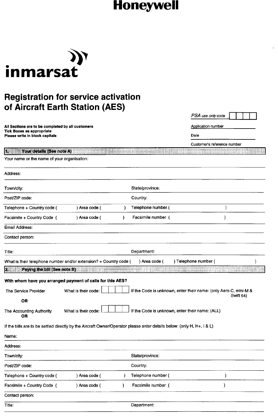
SYSTEM DESCRIPTION AND INSTALLATION MANUAL
HS--700 High Speed Data System
23--20--33
30 Aug 2002
Use or disclosure of information on this page is subject to the restrictions in the proprietary notice of this document.
Page A--2
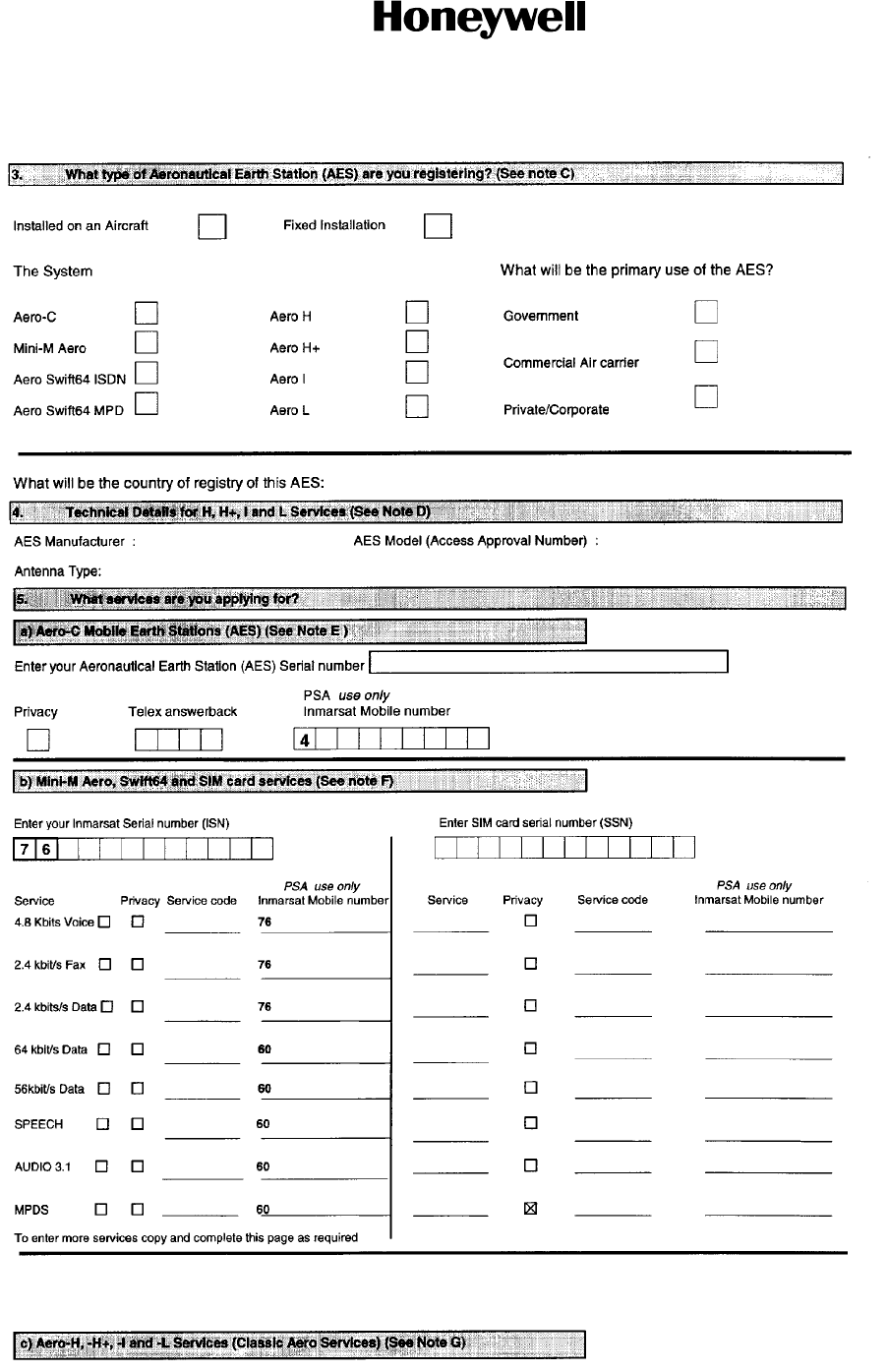
SYSTEM DESCRIPTION AND INSTALLATION MANUAL
HS--700 High Speed Data System
23--20--33
30 Aug 2002
Use or disclosure of information on this page is subject to the restrictions in the proprietary notice of this document.
Page A--3
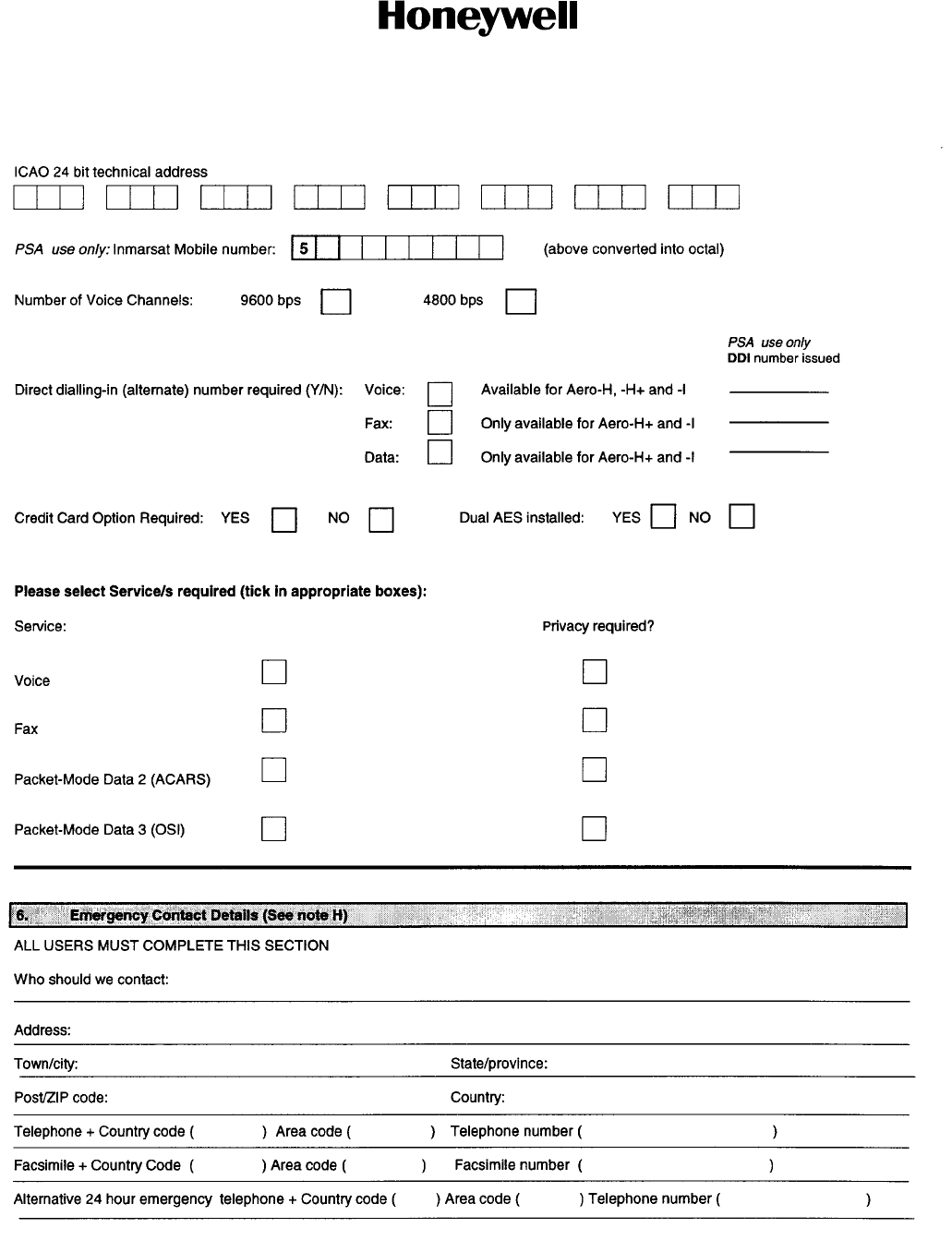
SYSTEM DESCRIPTION AND INSTALLATION MANUAL
HS--700 High Speed Data System
23--20--33
30 Aug 2002
Use or disclosure of information on this page is subject to the restrictions in the proprietary notice of this document.
Page A--4

SYSTEM DESCRIPTION AND INSTALLATION MANUAL
HS--700 High Speed Data System
23--20--33
30 Aug 2002
Use or disclosure of information on this page is subject to the restrictions in the proprietary notice of this document.
Page A--5
SYSTEM DESCRIPTION AND INSTALLATION MANUAL
HS--700 High Speed Data System
23--20--33
30 Aug 2002
Use or disclosure of information on this page is subject to the restrictions in the proprietary notice of this document.
Page A--6
SYSTEM DESCRIPTION AND INSTALLATION MANUAL
HS--700 High Speed Data System
23--20--33
30 Aug 2002
Use or disclosure of information on this page is subject to the restrictions in the proprietary notice of this document.
Page A--7
SYSTEM DESCRIPTION AND INSTALLATION MANUAL
HS--700 High Speed Data System
23--20--33
30 Aug 2002
Use or disclosure of information on this page is subject to the restrictions in the proprietary notice of this document.
Page A--8
SYSTEM DESCRIPTION AND INSTALLATION MANUAL
HS--700 High Speed Data System
23--20--33
30 Aug 2002
Use or disclosure of information on this page is subject to the restrictions in the proprietary notice of this document.
Page A--9
SYSTEM DESCRIPTION AND INSTALLATION MANUAL
HS--700 High Speed Data System
23--20--33
30 Aug 2002
Use or disclosure of information on this page is subject to the restrictions in the proprietary notice of this document.
Page A--10