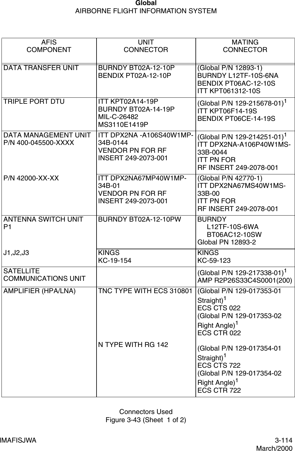
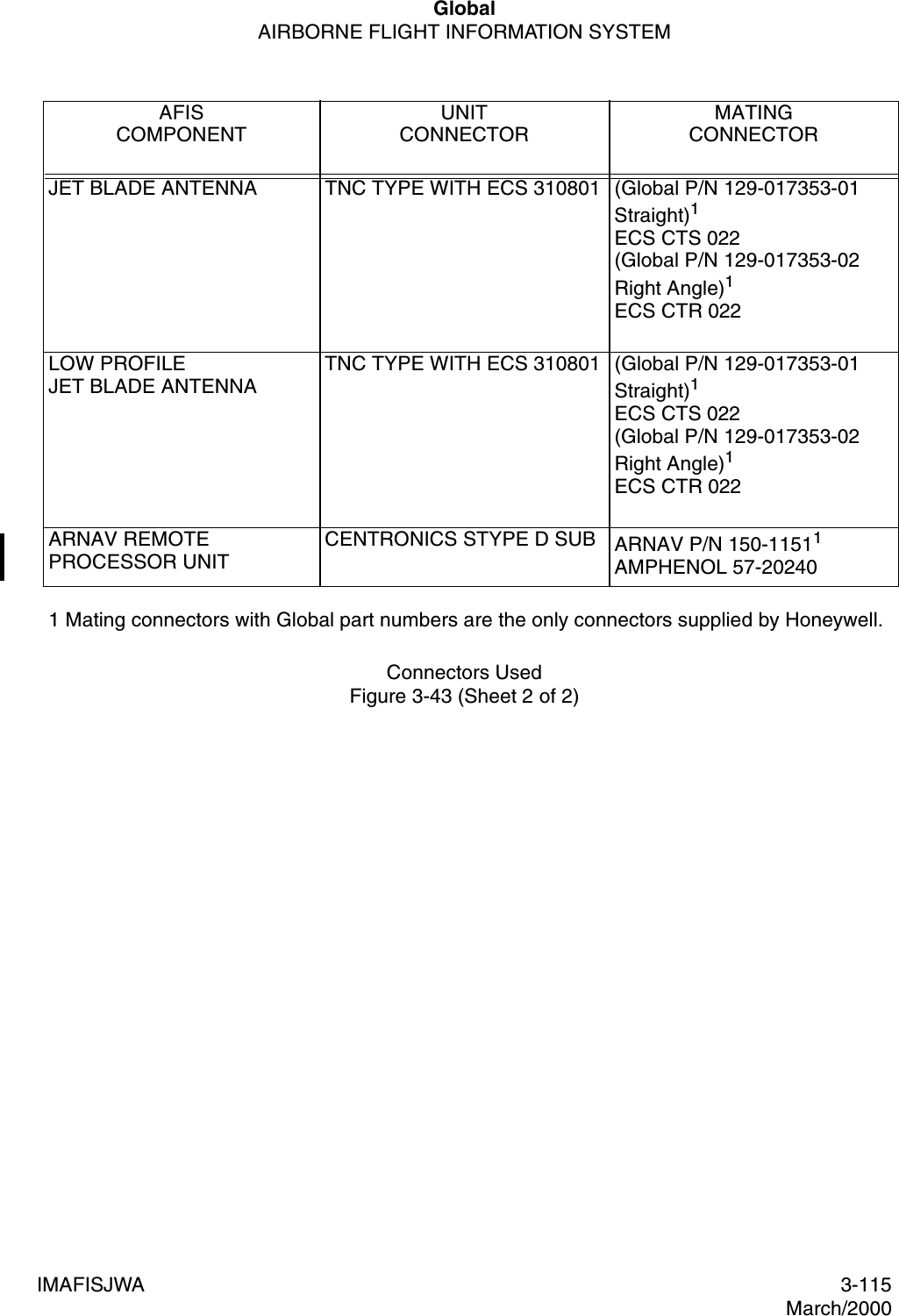
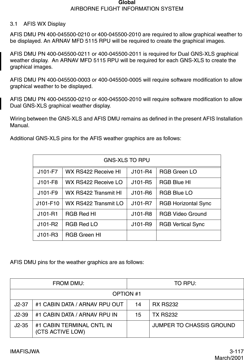
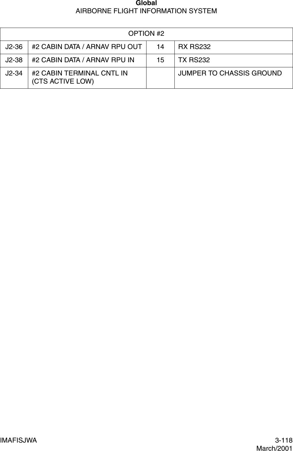
Honeywell MCX-1000A AVIATION DATA COMMUNICATIONS TRANSMITTER User Manual 150 1255 000
Honeywell International Inc. AVIATION DATA COMMUNICATIONS TRANSMITTER 150 1255 000
UserManual.wiki
>
Honeywell
>
MCX-1000A User Manual
>
USERS MANUAL 1
Contents
1.
USERS MANUAL 1
2.
USERS MANUAL 2
USERS MANUAL 1
Navigation menu
Upload a User Manual
Namespaces
Wiki Guide
HTML
PDF
Info
Views
User Manual
Discussion / Help
Navigation
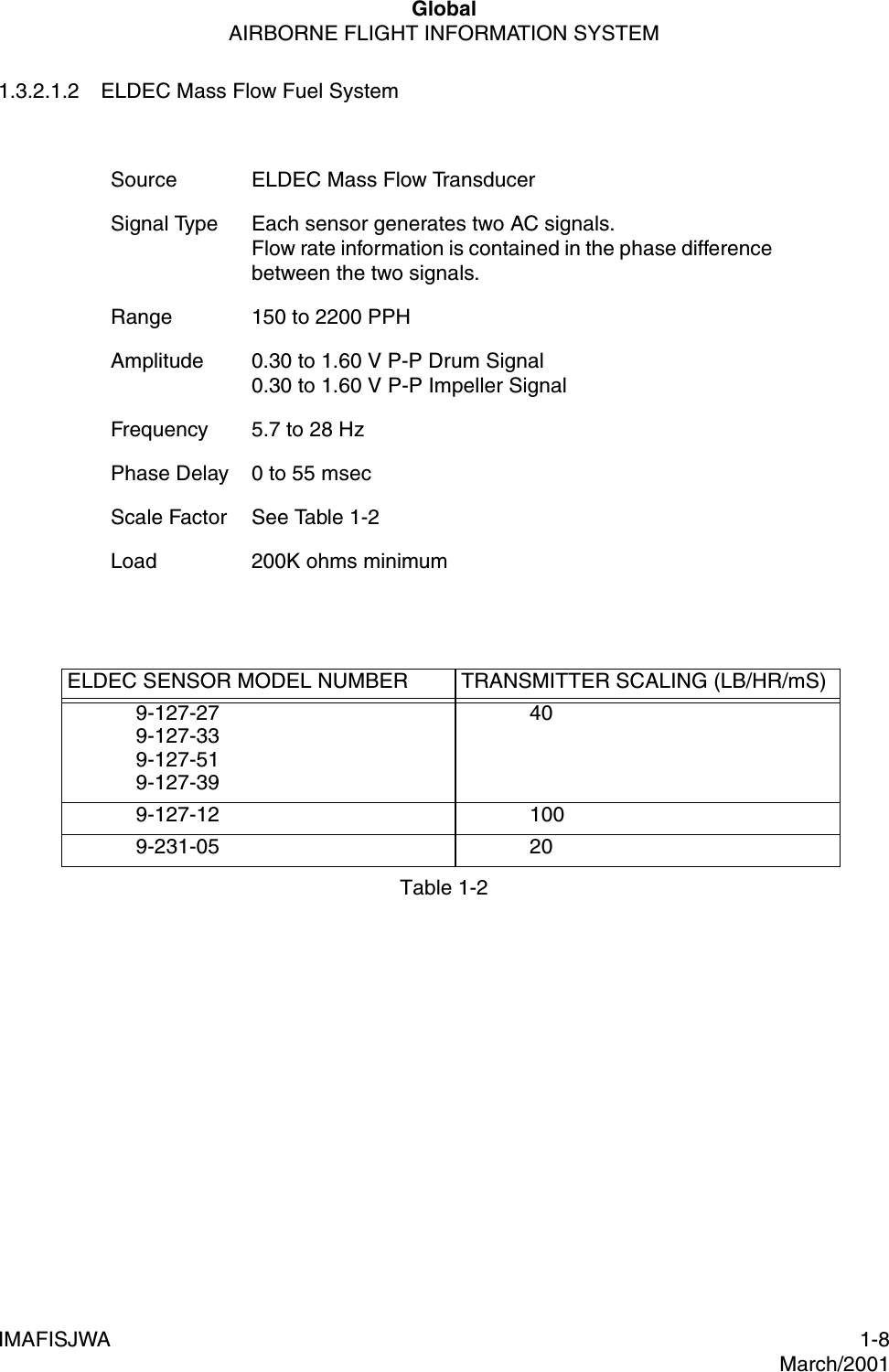
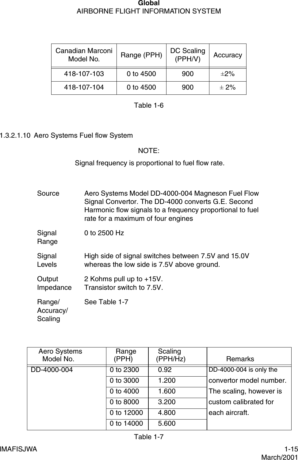
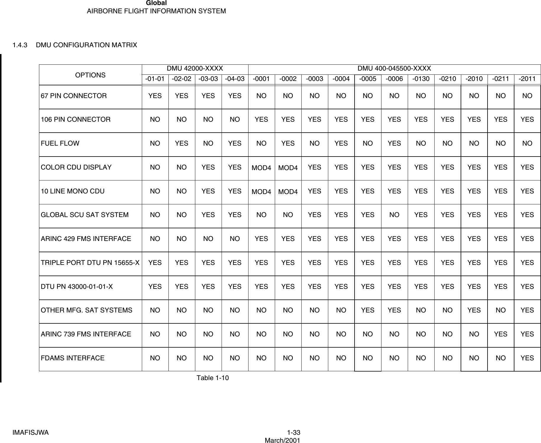
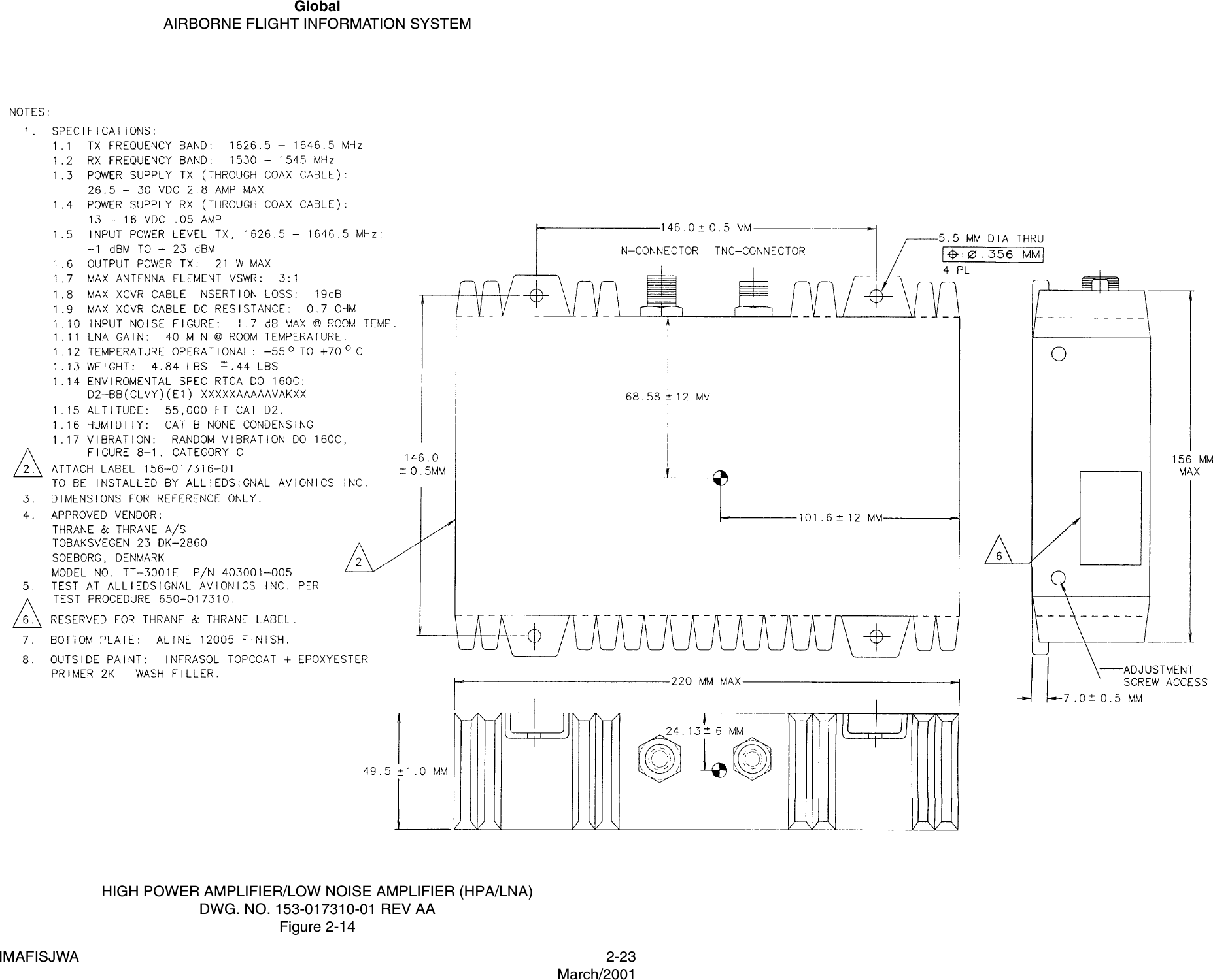
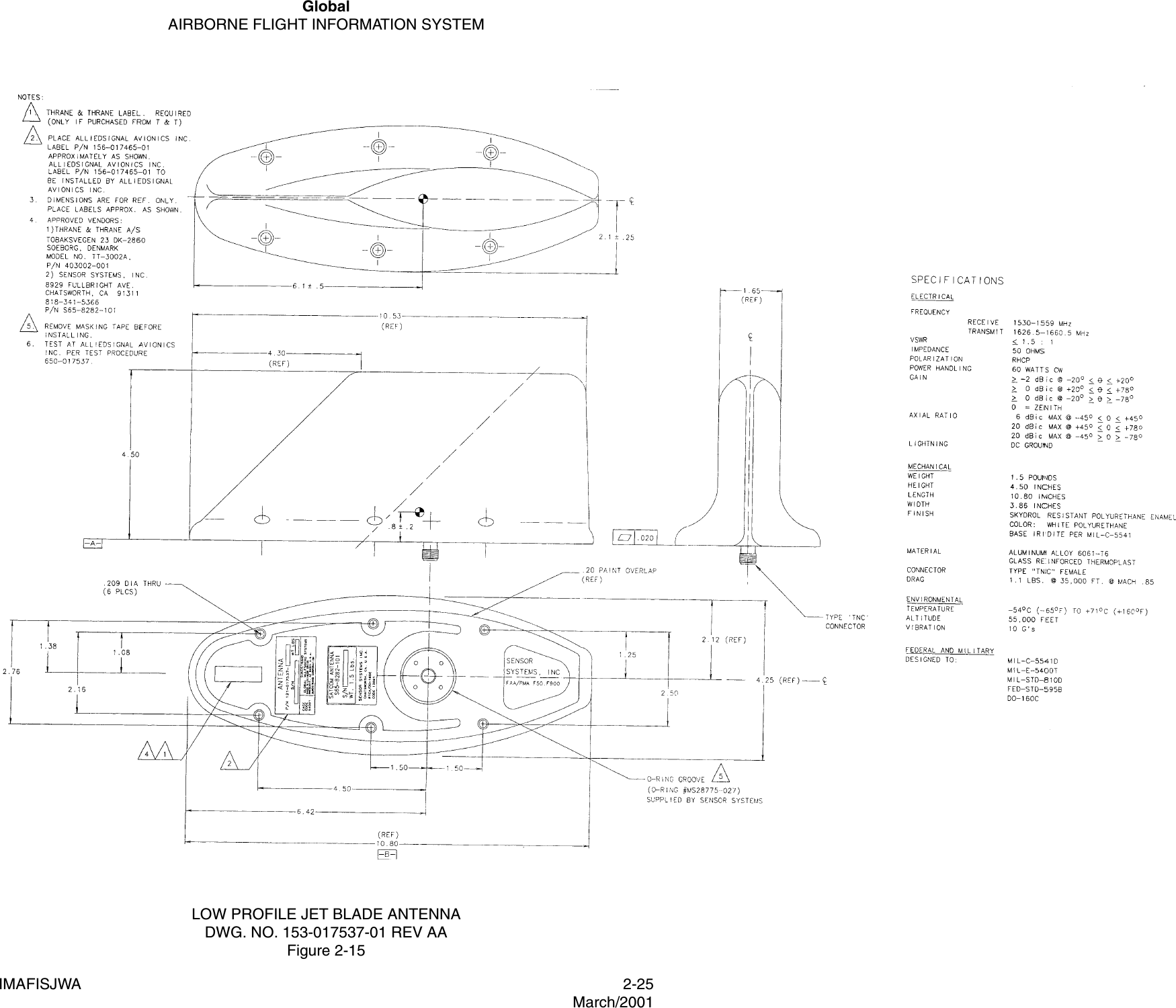
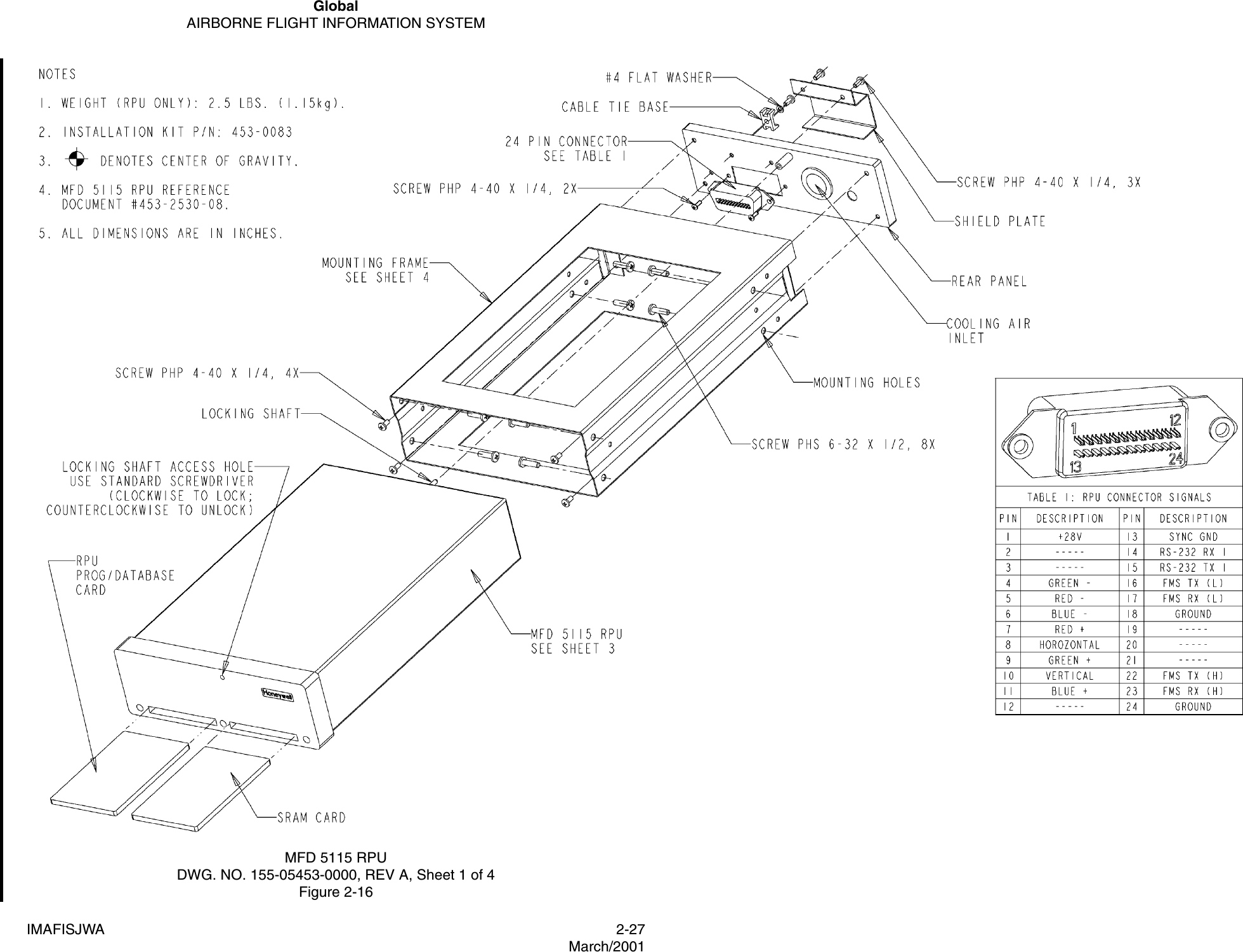
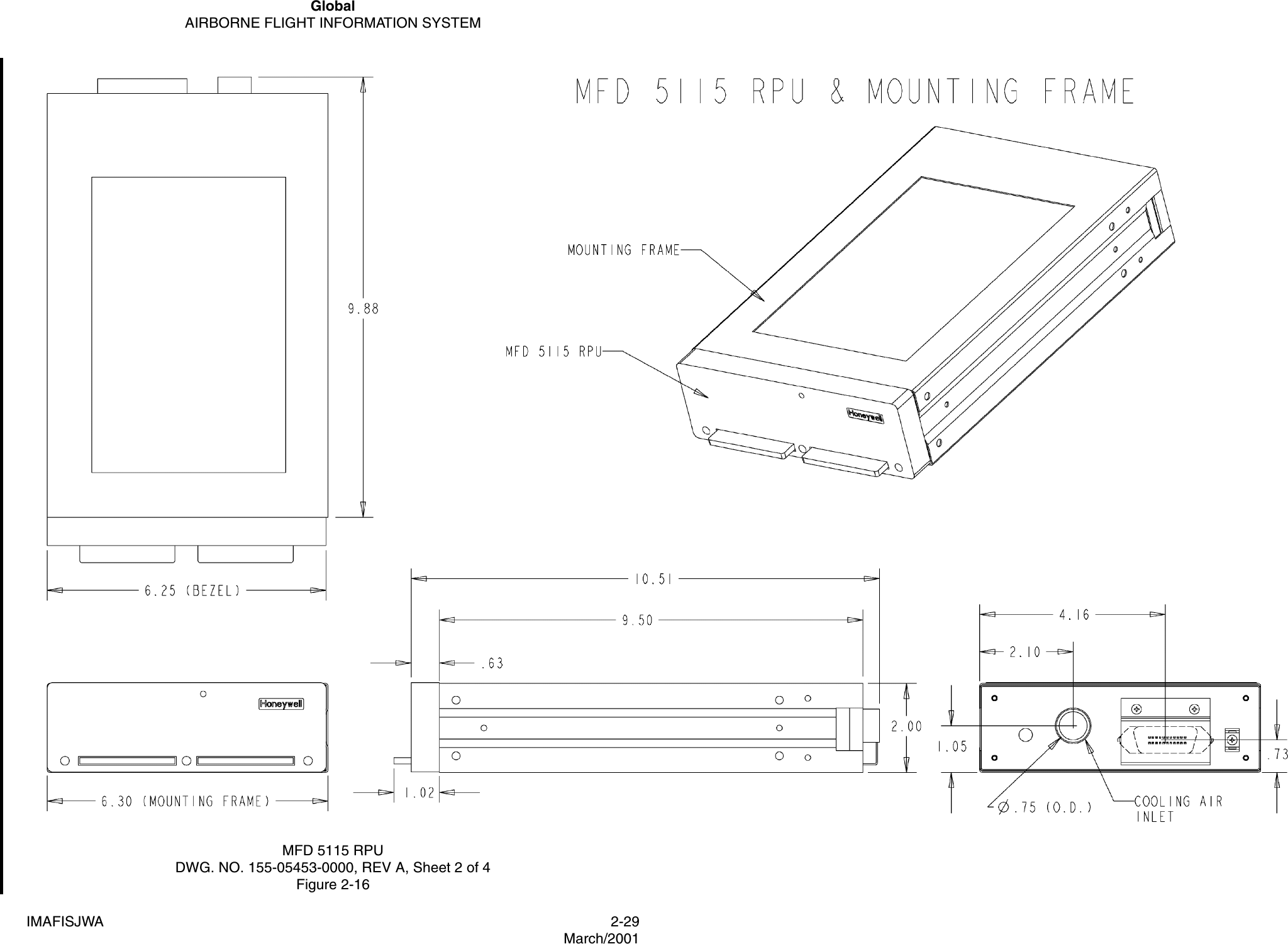
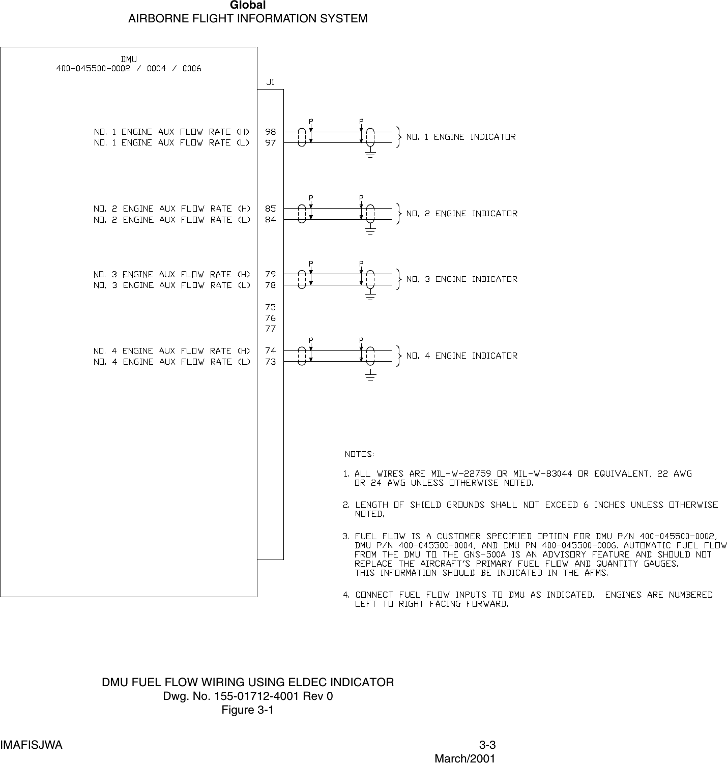
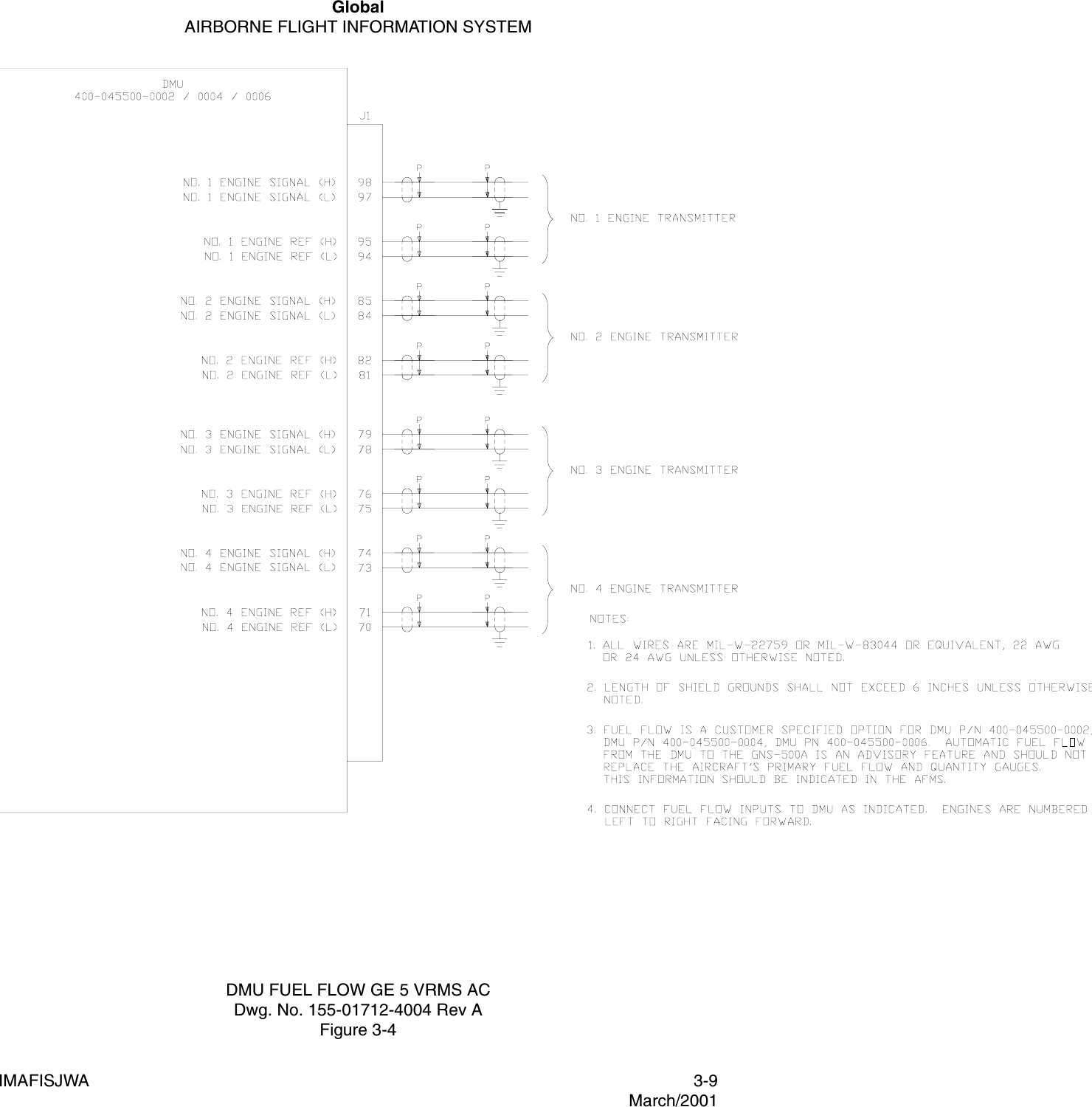
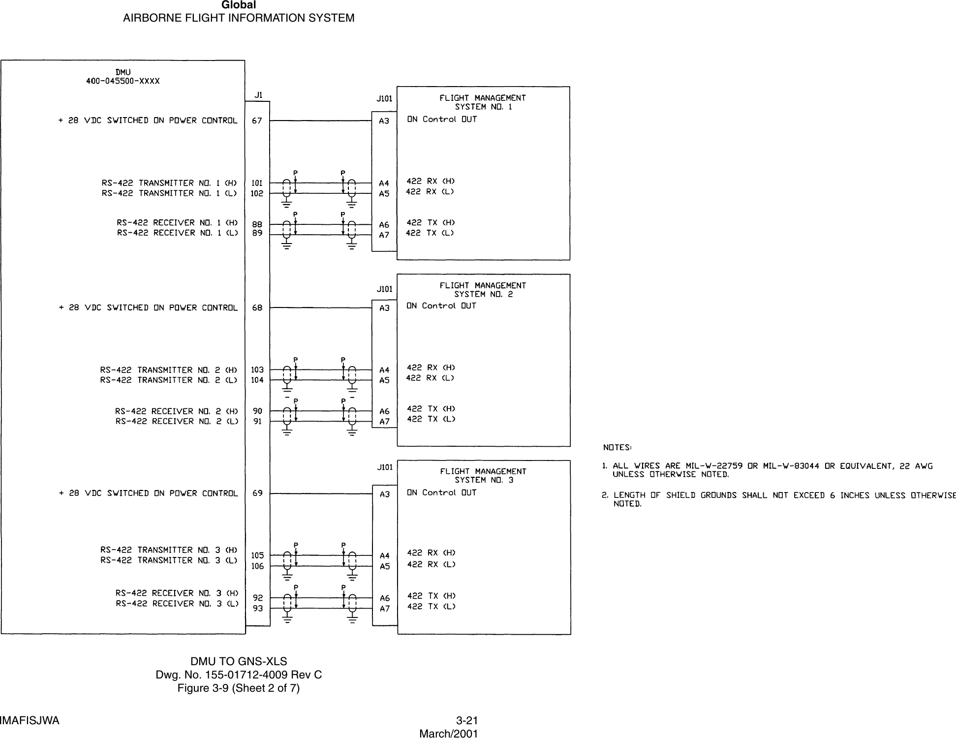
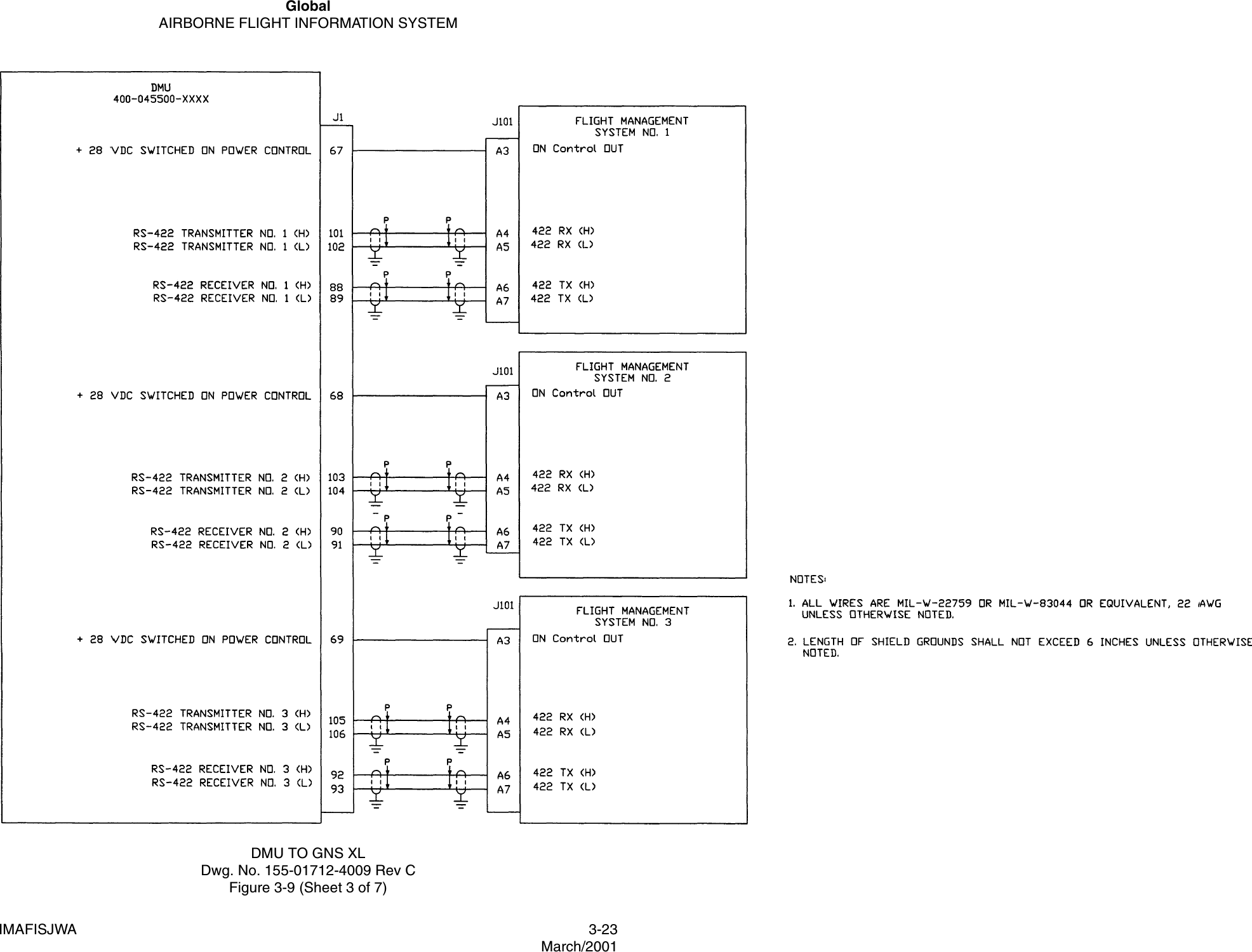
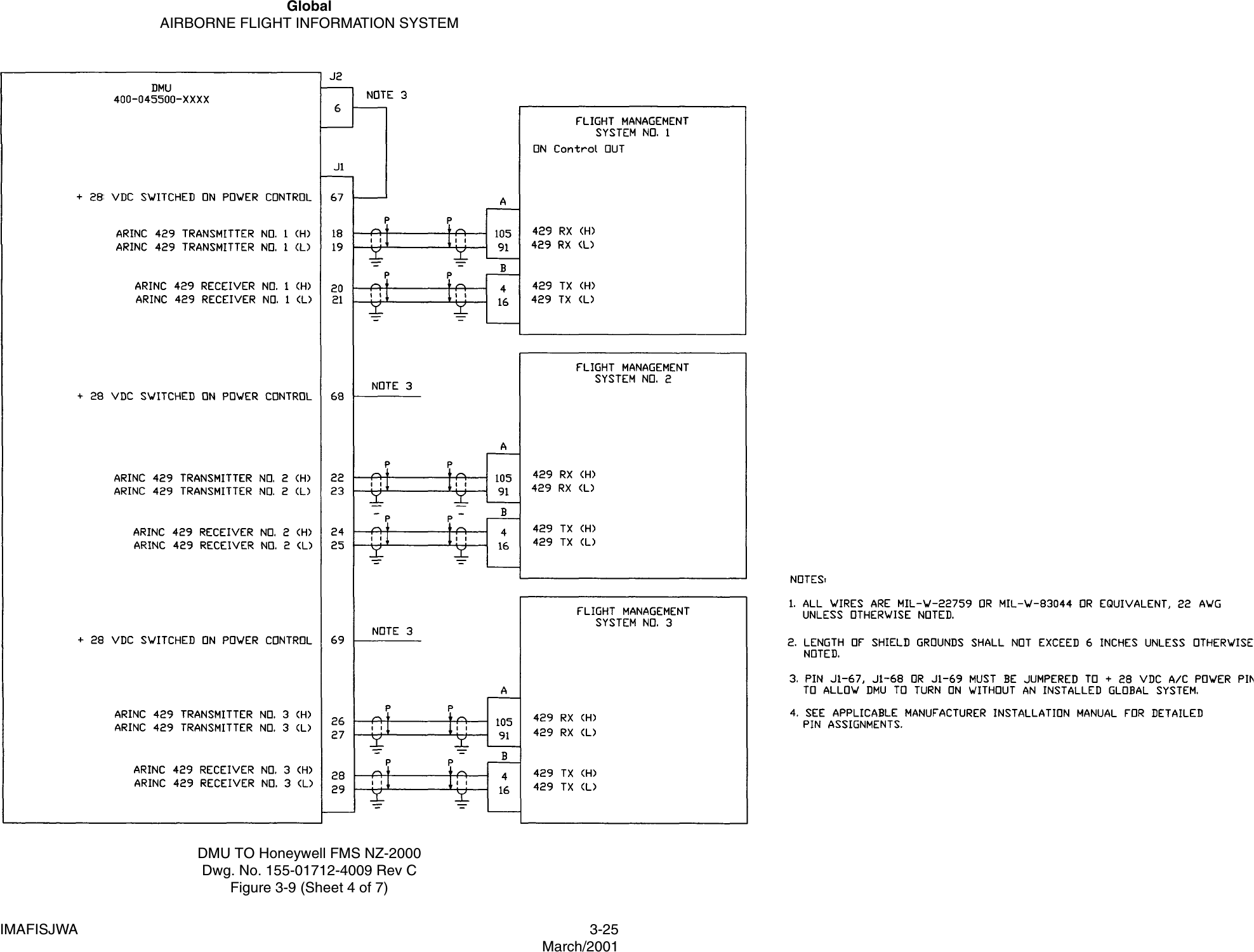
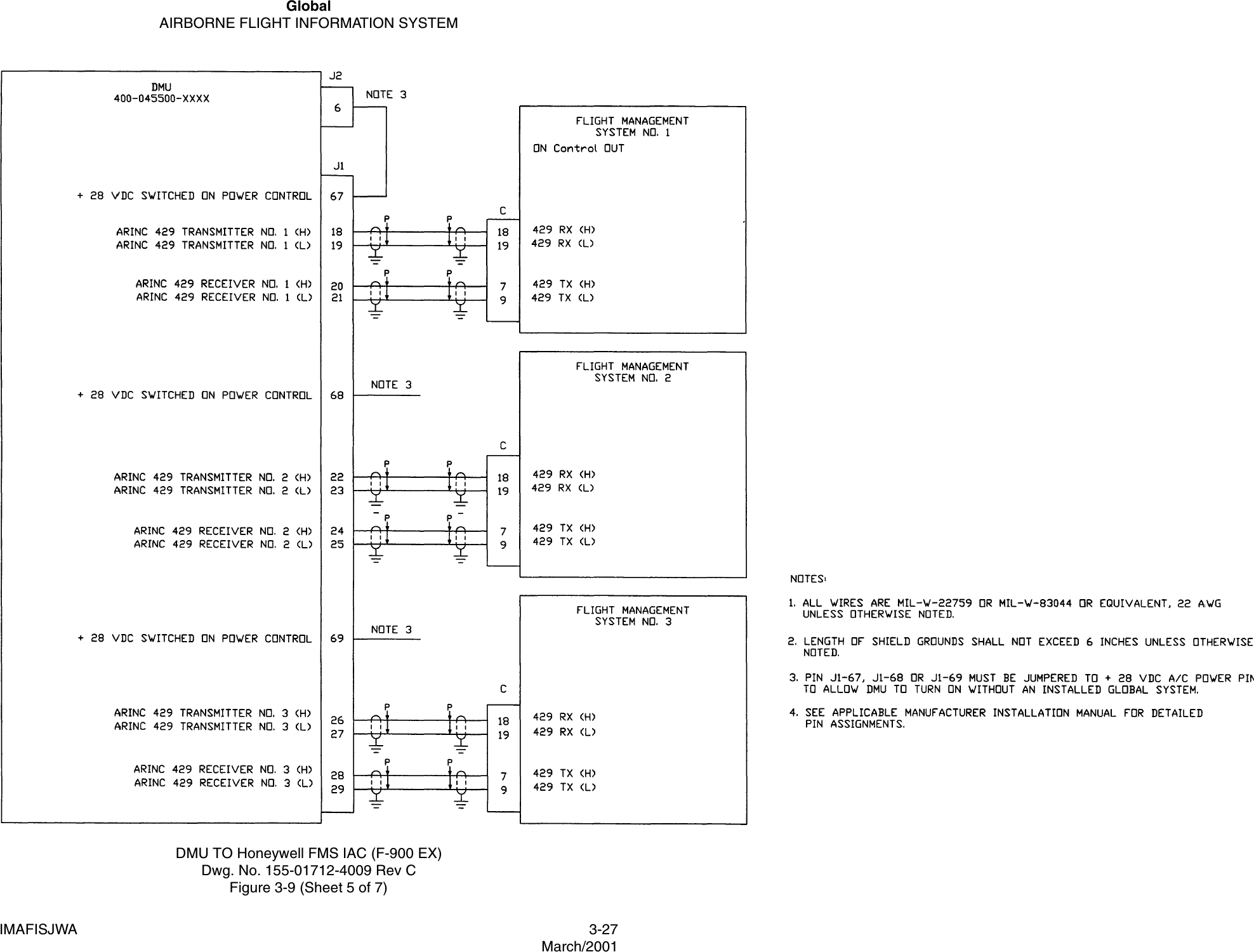
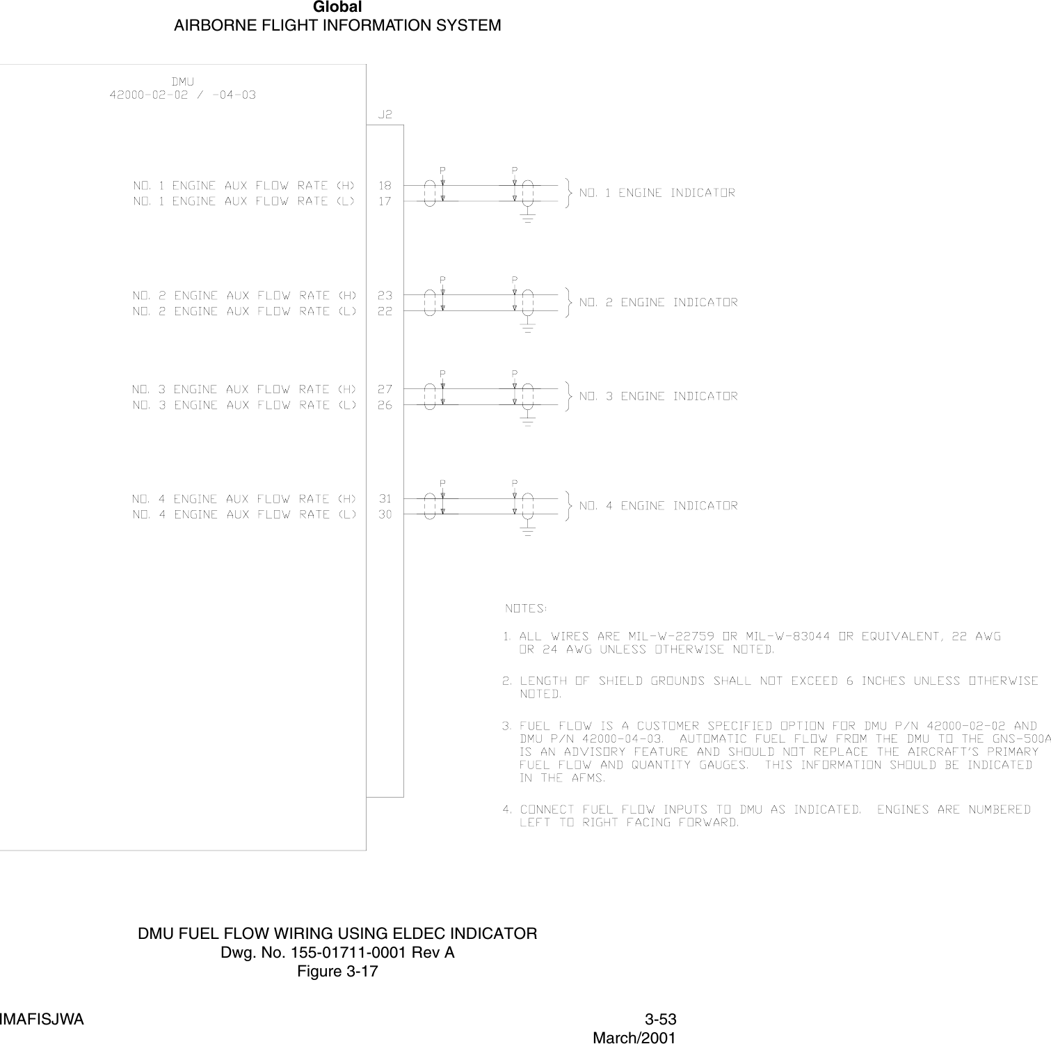
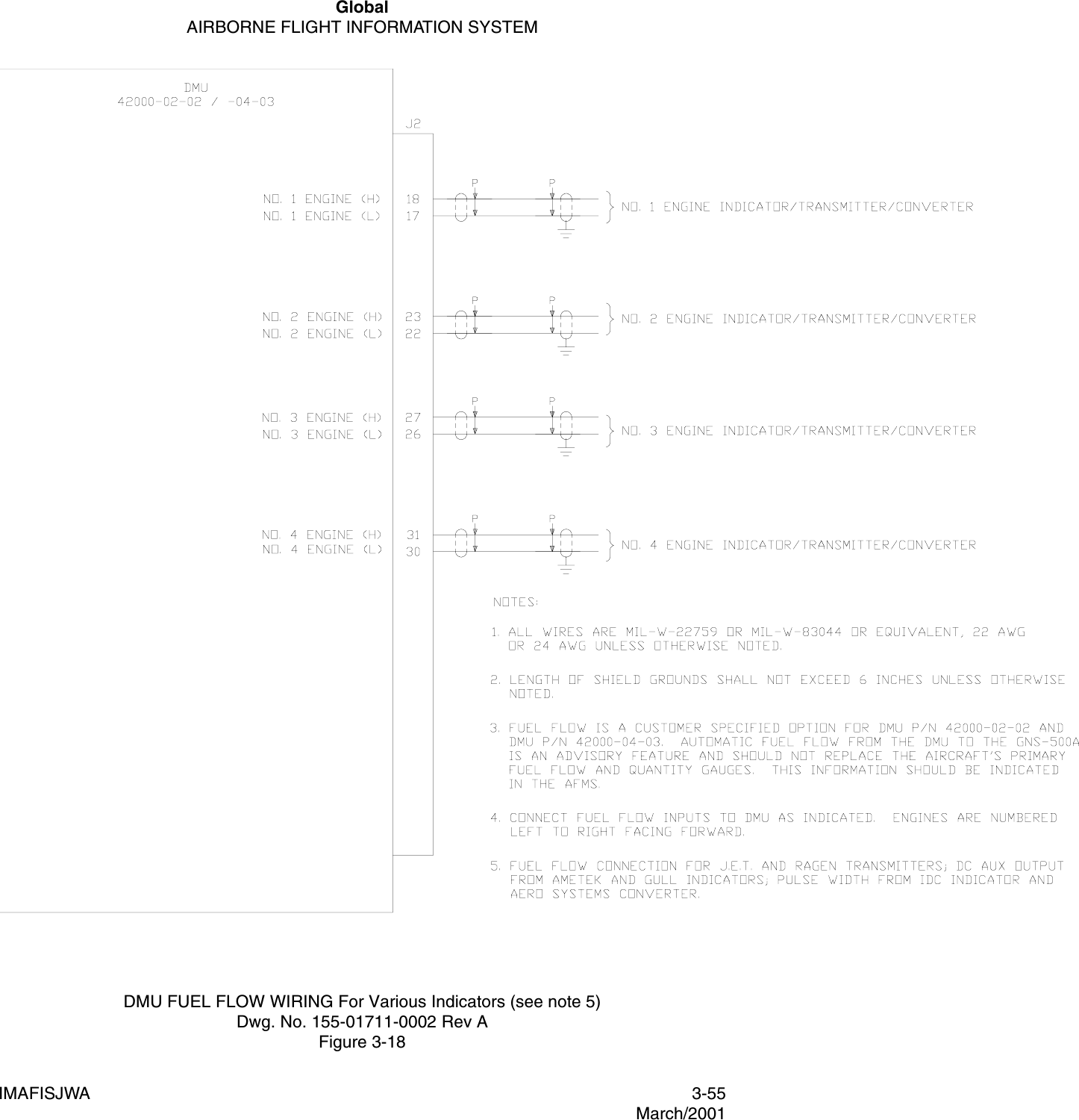
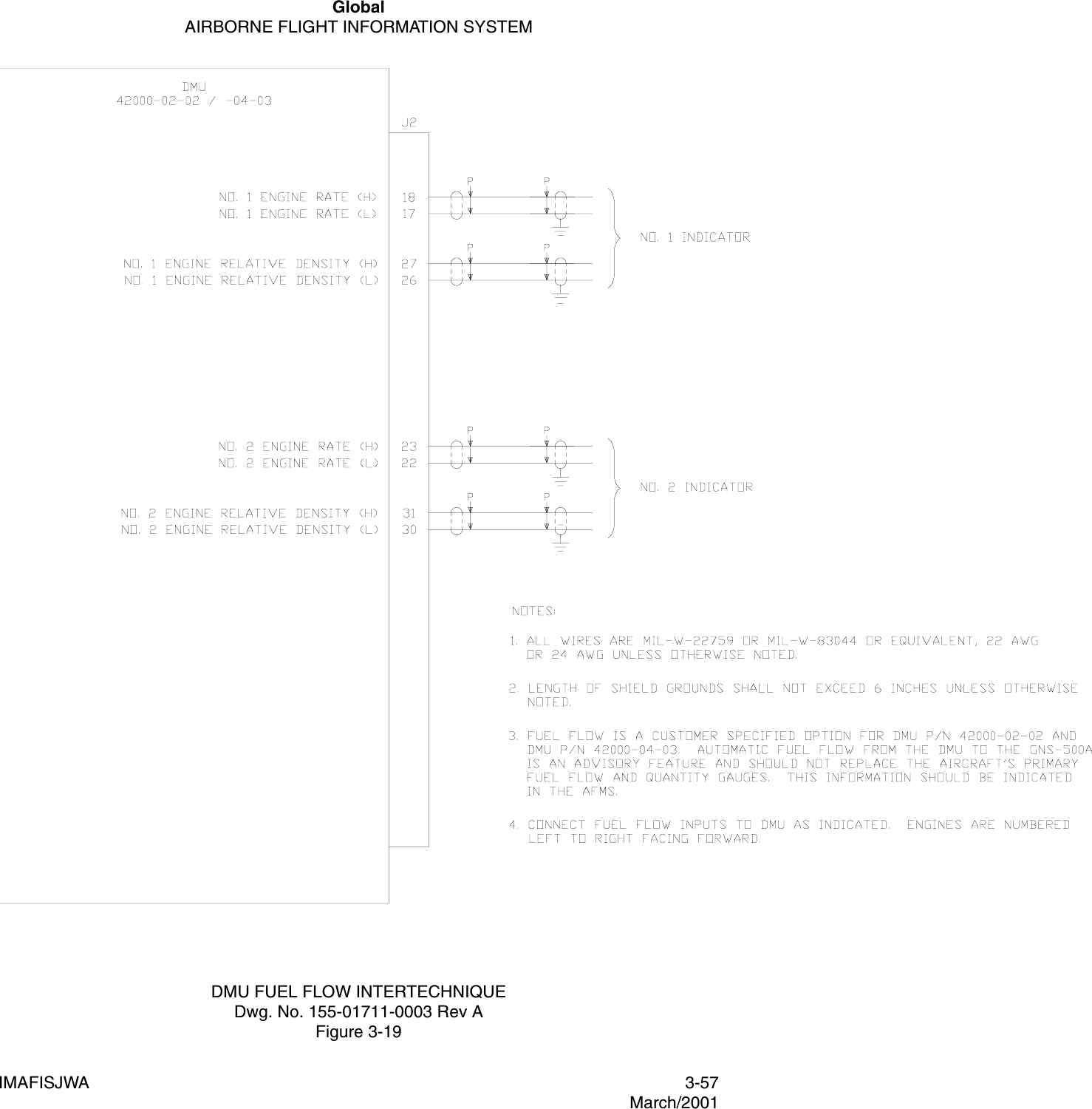
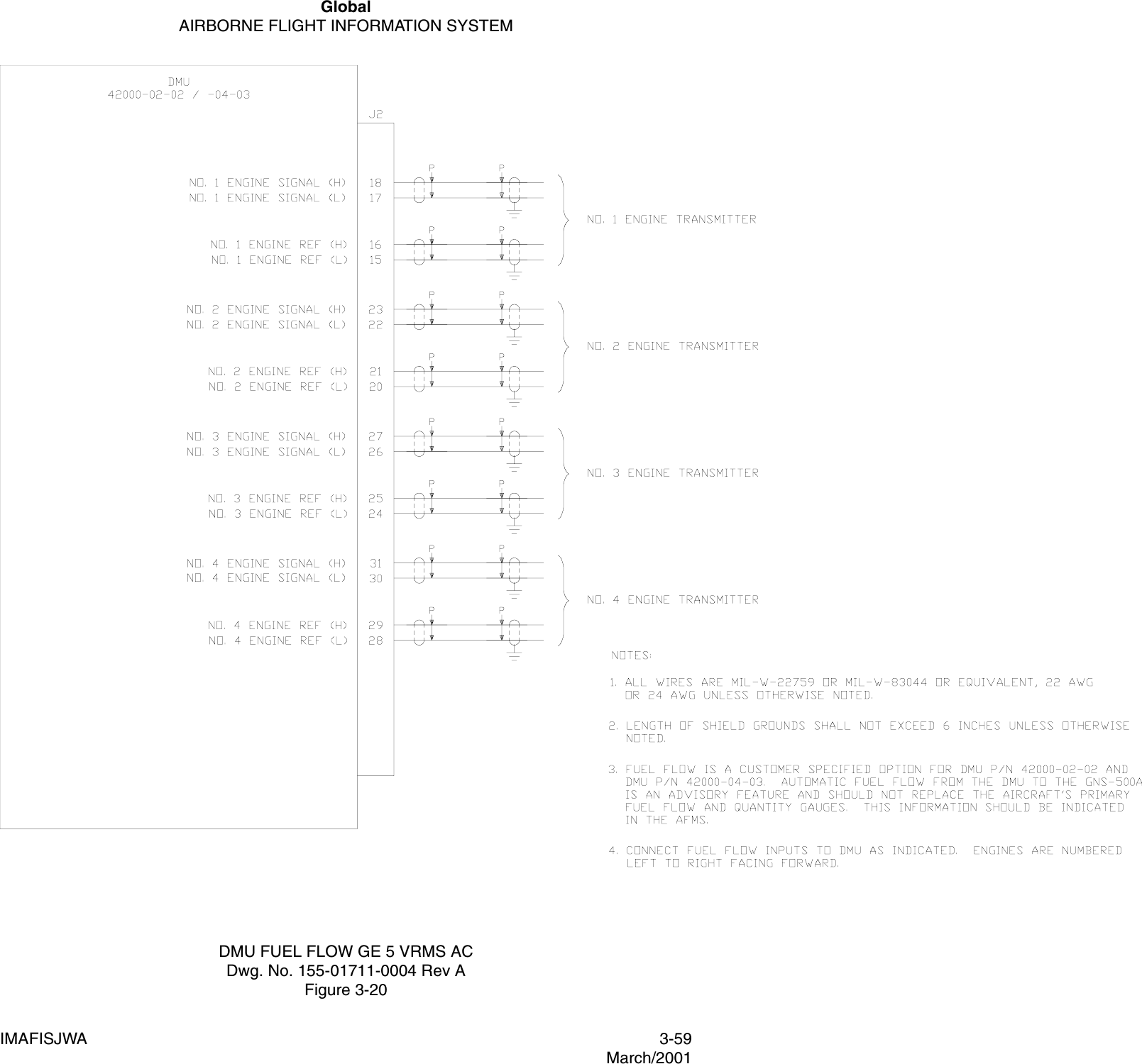
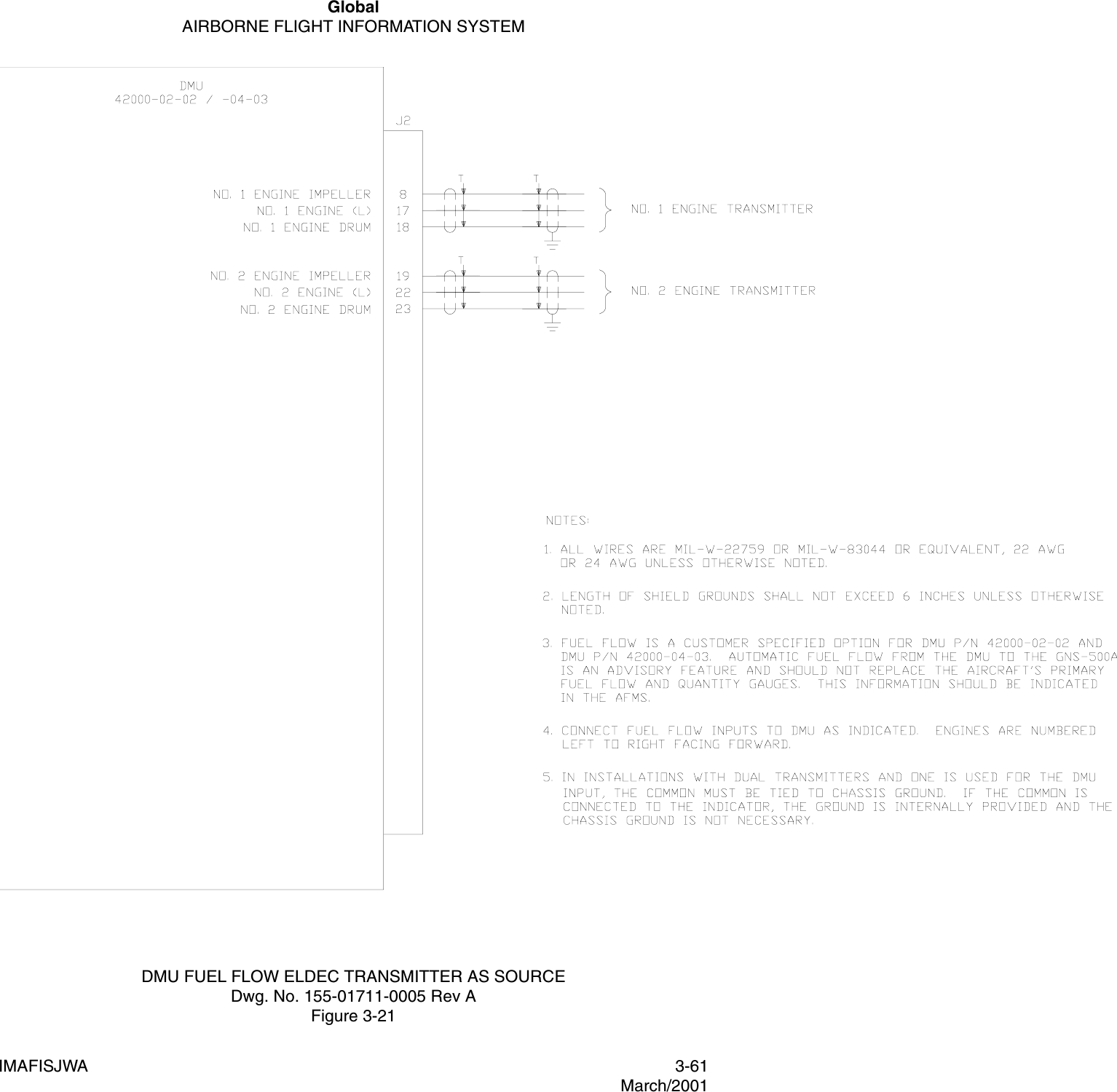
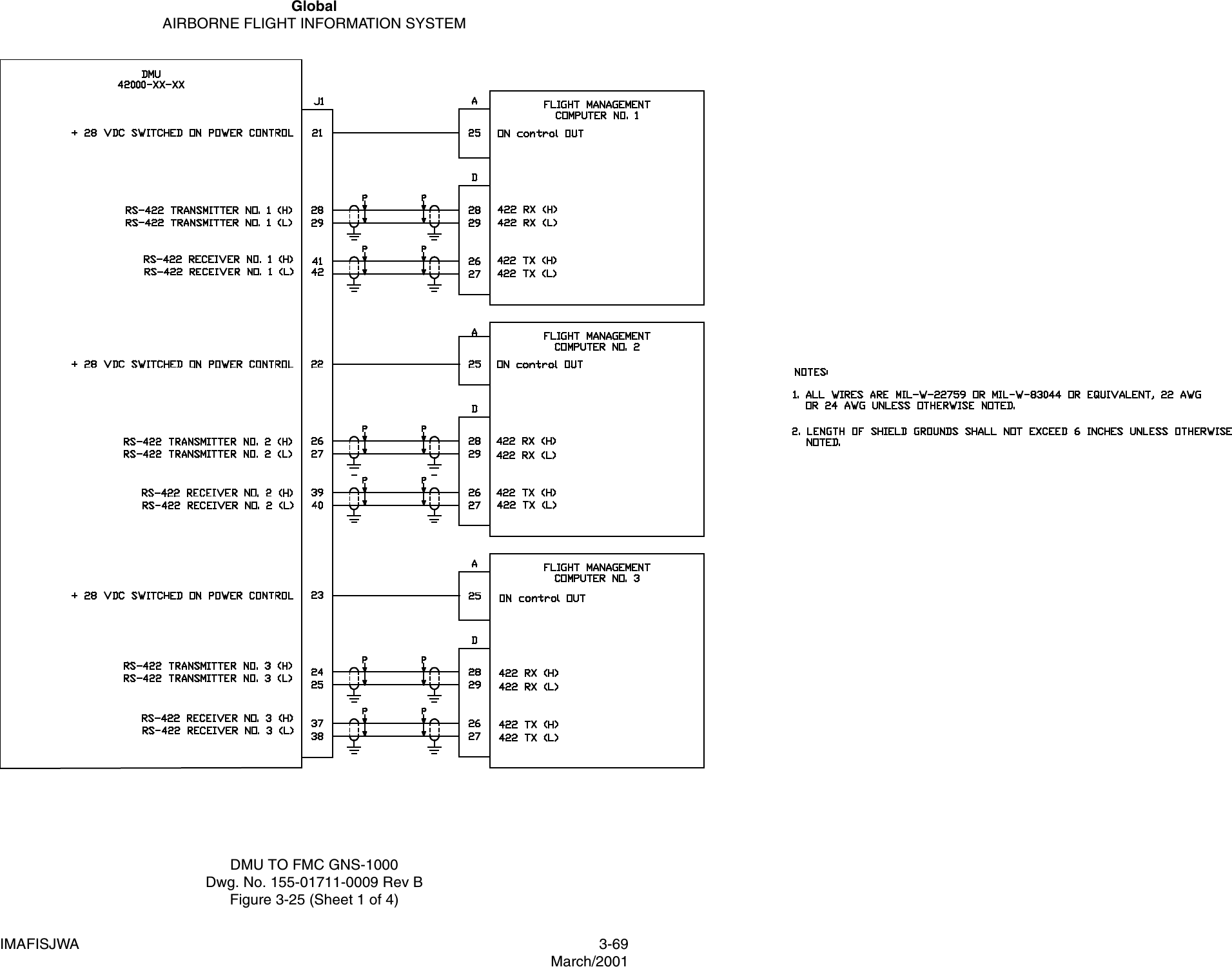
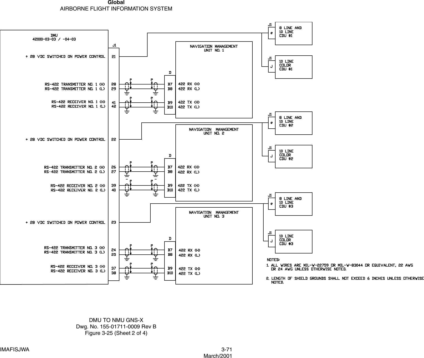
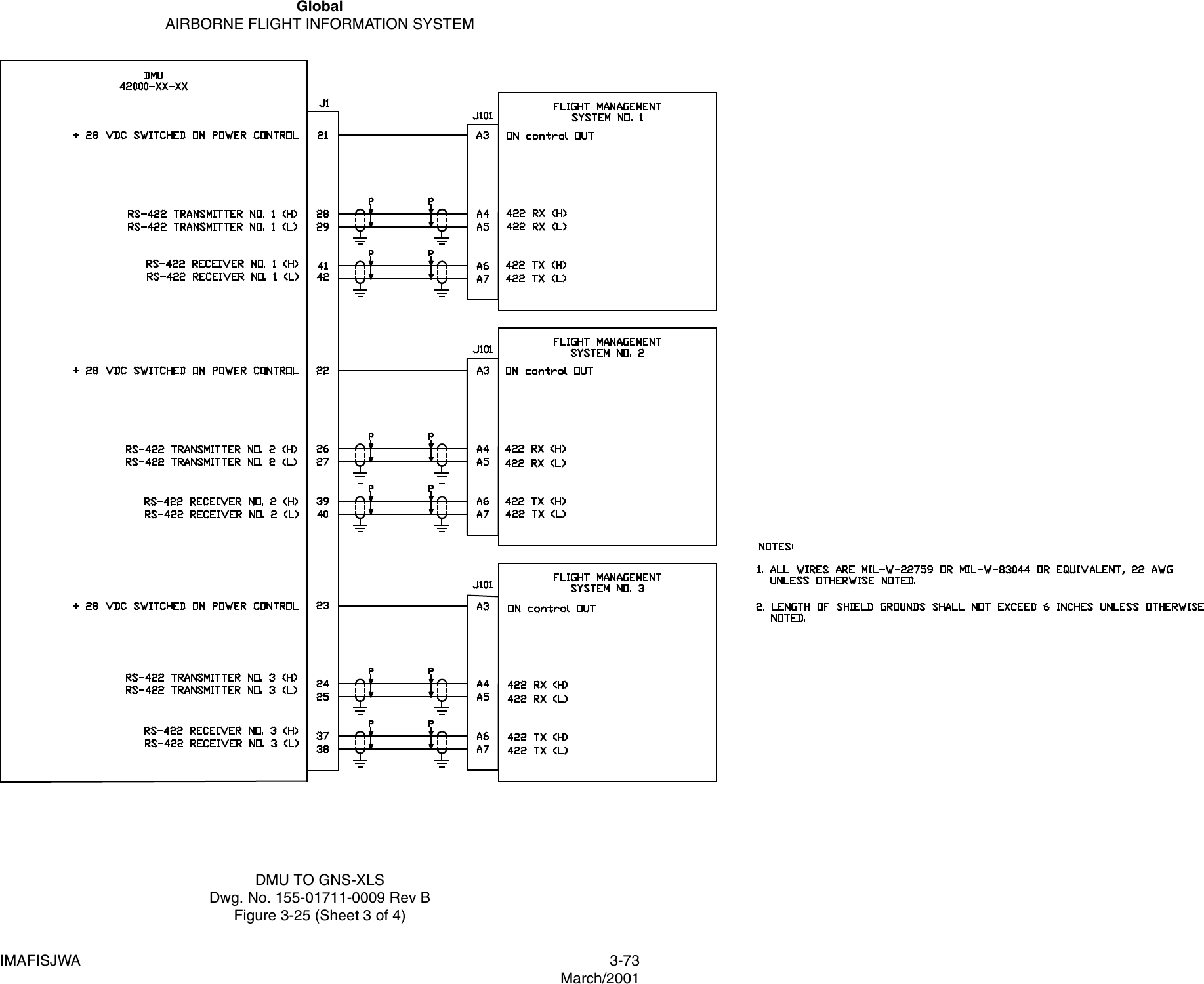
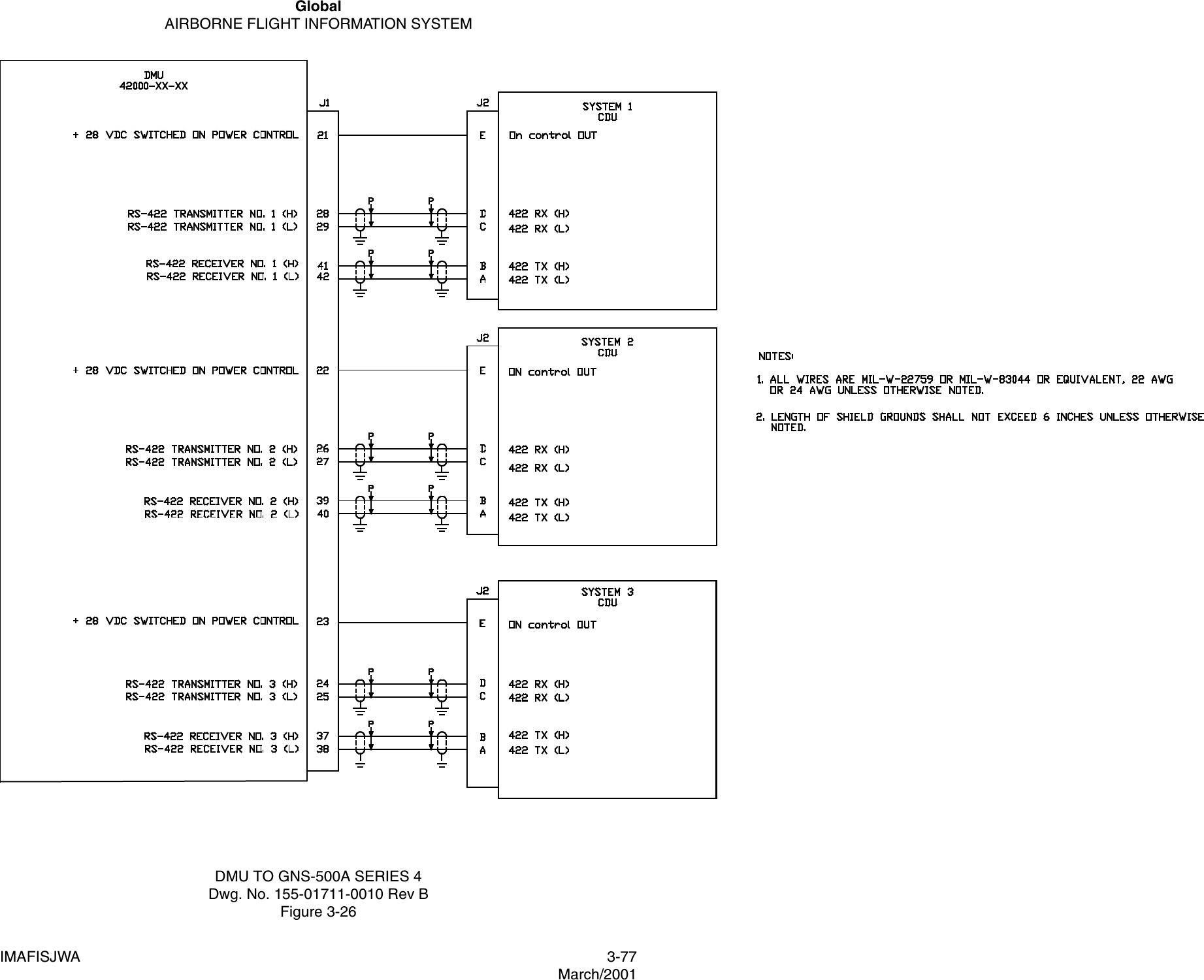
![GlobalAIRBORNE FLIGHT INFORMATION SYSTEMIMAFISJWA 1-16March/20011.3.2.1.11 Intertechnique Fuel flow SystemNOTE:Flow rate is proportional to frequency; the fuel relative density signalis a 3 to 5 VDC signal proportional to the fuel specific gravity(relative density). 1.3.2.2 RS-422A Serial Data Input1.3.2.2.1 Data Transfer Unit (DTU) Source Intertechnique totalizer amplifier indicator Models 723-161-1 and 723-161-2. The signals from the indicators are input to the totalizer.Range Reference0 to 2000 PPHScaling Flow = [Vsig/5.0] x 34.506 x frequencyWhere: Flow is PPH, Vsig = Voltage of density signal and Freq = Frequency of rate signalSignal: Frequency:Density:VOL = 0.7 ±TBD VVOH = 12.0 ±TBD VPulse width = 2.5 ±TBD VImpedance Output = 270 ohmsRange = 3 to 5.0 VDCOutput Impedance = 3.9 KohmsData Type Both transmit and receive data are two-wire, balanced voltage digital signals in accordance with EIA RS-422A electrical format.Receive Logic LevelLogic 1: +2 to +6V differentialLogic 0: -2 to -6V differentialData Rate 22.5 KBSBit Stream FormatAsynchronous with 1 start bit, 8 bits of data and 2 stop bits between words.Word Type 8 bit with no parity](https://usermanual.wiki/Honeywell/MCX-1000A.USERS-MANUAL-1/User-Guide-630214-Page-24.png)