Honeywell MCX-1000A AVIATION DATA COMMUNICATIONS TRANSMITTER User Manual 150 1255 000
Honeywell International Inc. AVIATION DATA COMMUNICATIONS TRANSMITTER 150 1255 000
Contents
- 1. USERS MANUAL 1
- 2. USERS MANUAL 2
USERS MANUAL 1

SYSTEM INSTALLATION MANUAL
AIRBORNE FLIGHT INFORMATION SYSTEM
MANUAL NUMBER 150-1255-000
REVISION 11 MARCH, 2001
n
Global ®
AFIS ®
400-045500-0001 through -0006
400-045500-0130 / -0210 / -2010 / -0211 / -2011
42000-01-01, -02-02, -03-03, -04-03
WARNING
Prior to export of this document, review for export license requirement is needed.
COPYRIGHT NOTICE
2000-2001 Honeywell International Inc.
Reproduction of this publication or any portion thereof by any means without the expressed
written permission of Honeywell is prohibited. For further information, contact the Manager
of Technical Publications, Honeywell, Olathe, Kansas 66061. (913) 782-0400
Global
AIRBORNE FLIGHT INFORMATION SYSTEM
IMAFISJWA i
March/2001
SECTION 1
GENERAL INFORMATION
Paragraph Page
1.1 INTRODUCTION 1-1
1.2 EQUIPMENT DESCRIPTION 1-1
1.2.1 DATA MANAGEMENT UNIT 1-1
1.2.2 ANTENNA SWITCHING UNIT 1-1
1.2.3 DATA TRANSFER UNIT 1-1
1.2.4 SATELLITE COMMUNICATION UNIT 1-2
1.2.5 HIGH POWER AMPLIFIER/LOW NOISE AMPLIFIER 1-2
1.2.6 SATELLITE ANTENNA 1-2
1.2.7 CONFIGURATION MODULE 1-2
1.2.8 ARNAV MFD 5115 RPU 1-2
1.3 TECHNICAL CHARACTERISTICS 1-3
1.3.1 UNIT SPECIFICATIONS 1-3
1.3.2 SYSTEM SPECIFICATIONS 1-7
1.3.2.1 FUEL FLOW INPUT (ANALOG INPUT) 1-7
1.3.2.2 RS-422A SERIAL DATA INPUT 1-16
1.3.2.3 ARINC 429 INPUT 1-18
1.3.2.4 ANALOG OUTPUTS (DMU) 1-19
1.3.2.5 RS-422A SERIAL DIGITAL OUTPUTS (DMU) 1-20
1.3.2.6 ARINC 429 OUTPUTS 1-21
1.3.2.7 PRINTER INTERFACE 1-22
1.3.2.8 CABIN TERMINAL INTERFACE 1-24
1.3.2.9 DISCRETE INPUTS 1-26
1.4 UNITS AND ACCESSORIES SUPPLIED 1-29
1.4.1 DATA MANAGEMENT UNIT 1-29
1.4.2 FLIGHT PLANNING SERVICE 1-30
1.4.3 DMU CONFIGURATION MATRIX 1-33
1.5 ACCESSORIES REQUIRED 1-35
1.5.1 DMU INSTALLATION KIT 1-35
1.5.2 CONFIGURATION MODULE UNIT 1-35
1.5.3 VHF ANTENNA 1-35
1.6 OPTIONAL ACCESSORIES 1-35
1.6.1 DATA TRANSFER UNIT 1-35
1.6.2 ANTENNA SWITCHING UNIT 1-36
1.6.3 SATELLITE SYSTEM (SATAFIS) 1-37
1.6.4 PRINTER 1-37
1.6.5 CABIN PERSONAL COMPUTER 1-37
1.7 LICENSE REQUIREMENTS 1-37
1.7.1 VHF RADIO 1-37
1.7.2 INMARSAT SATELLITE APPROVAL 1-37
1.7.3 ARNAV RPU INSTALLATION KIT 1-38
1.8 INSTRUCTIONS FOR CONTINUED AIRWORTHINESS 1-38
Global
AIRBORNE FLIGHT INFORMATION SYSTEM
IMAFISJWA ii
March/2001
SECTION 2
MECHANICAL INSTALLATION
Paragraph Page
2.0 INTRODUCTION 2-1
2.1 UNPACKING AND INSPECTING EQUIPMENT 2-1
2.2 GENERAL INSTALLATION REQUIREMENTS 2-1
2.3 DATA MANAGEMENT UNIT (DMU) INSTALLATION 2-2
2.4 DATA TRANSFER UNIT (DTU) INSTALLATION 2-2
2.5 CONFIGURATION MODULE 2-2
2.6 SATELLITE COMMUNICATION UNIT (SCU) INSTALLATION 2-3
2.7 HPA/LNA INSTALLATION 2-3
2.8 ANTENNA INSTALLATION 2-3
2.8.1 BONDING CHECKLIST 2-3
2.8.2 LOW PROFILE JET BLADE ANTENNA INSTALLATION 2-3
2.9 ARNAV RPU INSTALLATION 2-4
2.9.1 INSTALLATION KIT 2-4
2.9.2 INSTALLATION GUIDE 2-4
2.9.3 COOLING CONSIDERATIONS 2-4
2.9.4 INSTALLATION CONSIDERATIONS 2-4
2.9.5 DATABASE CARD 2-4
SECTION 3
ELECTRICAL INSTALLATION
3.0 GENERAL INFORMATION 3-1
3.1 AFIS WX DISPLAY 3-117
SECTION 4
AFIS CONFIGURATION AND CHECKOUT
Paragraph Page
4.0 GENERAL 4-1
4.0.1 SPECIAL EQUIPMENT AND MATERIALS 4-1
4.0.2 GENERAL 4-1
4.1 CONFIGURATION MODULE PROGRAMMING 4-4
FOR GNS-500A SERIES 4/5 WITH DMU P/N 42000-XX-XX
4.2 CONFIGURATION MODULE PROGRAMMING FOR GNS-500A SERIES 4-19
FOR GNS-500A SERIES 4/5 WITH DMU P/N 400-045500-XXXX
4.3 CONFIGURATION MODULE PROGRAMMING FOR GNS-1000, 4-33
GNS X, GNS-XES, GNS-XL OR GNS-XLS WITH DMU P/N 42000-01-01
OR 42000-03-03
Global
AIRBORNE FLIGHT INFORMATION SYSTEM
IMAFISJWA iii
March/2001
SECTION 4
AFIS CONFIGURATION AND CHECKOUT (cont)
4.4 CONFIGURATION MODULE PROGRAMMING FOR GNS-1000, 4-44
GNS X, GNS-XES, GNS-XL OR GNS-XLS WITH DMU P/N
400-045500-0001, -003, OR -005 AND OTHER FMS MANUFACTURES
USING DMU P/N 400-045500-0001, -0002, -0003, -0004, -0005, -0006
OR -0130
4.5 CONFIGURATION MODULE PROGRAMMING FOR GNS-1000, GNS-X, 4-59
GNS-XES, GNS-XL OR GNS-XLS WITH DMU P/N 400-045500-0210 OR
400-045500-2010.
4.6 CONFIGURATION MODULE PROGRAMMING FOR GNS-1000, GNS-X, 4-75
GNS-XES, GNS-XL OR GNS-XLS WITH DMU P/N 400-045500-0211 OR
400-045500-2011.
4.7 CONFIGURATION MODULE PROGRAMMING FOR 739 MCDU AND 4-92
OTHER FMS MANUFACTURERS WITH DMU P/N 400-045500-2011 OR
0211.
4.8 AFIS DATA MANAGEMENT UNIT (DMU) (ProComm Plus Reconfiguration 4-101
Procedure)
4.9 GENERAL 4-109
4.10 SYSTEM TEST AND CHECKOUT WITH CUSTOMER SUPPLIED 4-109
PRE-PROGRAMMED AFIS DISK
LIST OF ILLUSTRATIONS
Figure Page
1-1 AFIS GRAPHICS SERVICE AND DATABASE APPLICATION 1-31
2-1 DMU PN 42000-XX-XX or 400-045500-XXXX 2-5
2-2 DMU TRAY PN 42701-1 2-6
2-3 CONFIGURATION MODULE MOUNTING PROVISION P/N 31990-1 2-7
2-4 CONFIGURATION MODULE OUTLINE AND MOUNTING P/N 31990-1 2-8
2-5 DATA TRANSFER UNIT (DTU) PN 43000-01-01-X 2-9
2-6 TRIPLE PORT DTU PN 15655-XXXX 2-11
2-7 DTU DZUS MOUNTING 2-13
2-8 DTU TRAY MOUNTING 2-13
2-9 DTU INSTRUMENT PANEL MOUNTING PROVISION 2-14
2-10 DTU TRAY PN 43010-X 2-15
2-11 ANTENNA SWITCHING UNIT (ASU) PN 44000-1 2-17
2-12 SATELLITE COMMUNICATION UNIT (SCU) 2-19
2-13 SCU TRAY PN 300-317337-01 2-21
2-14 HIGH POWER AMPLIFIER / LOW NOISE AMPLIFIER (HPA / LNA) 2-23
2-15 LOW PROFILE JET BLADE ANTENNA 2-25
2-16 MFD 5115 RPU 2-27
Global
AIRBORNE FLIGHT INFORMATION SYSTEM
IMAFISJWA iv
March/2001
LIST OF ILLUSTRATIONS (cont)
Figure Page
3-1 DMU FUEL FLOW WIRING USING ELDEC INDICATOR 3-3
3-2 DMU FUEL FLOW WIRING FOR VARIOUS INDICATORS 3-5
3-3 DMU FUEL FLOW INTERTECHNIQUE 3-7
3-4 DMU FUEL FLOW GE 5 VRMS AC 3-9
3-5 DMU FUEL FLOW ELDEC TRANSMITER AS SOURCE 3-11
3-6 DMU TO TRIPLE PORT DTU 3-13
3-7 DMU TO DTU PN 43000-01-01-3 AND PN 43000-01-01-4 3-15
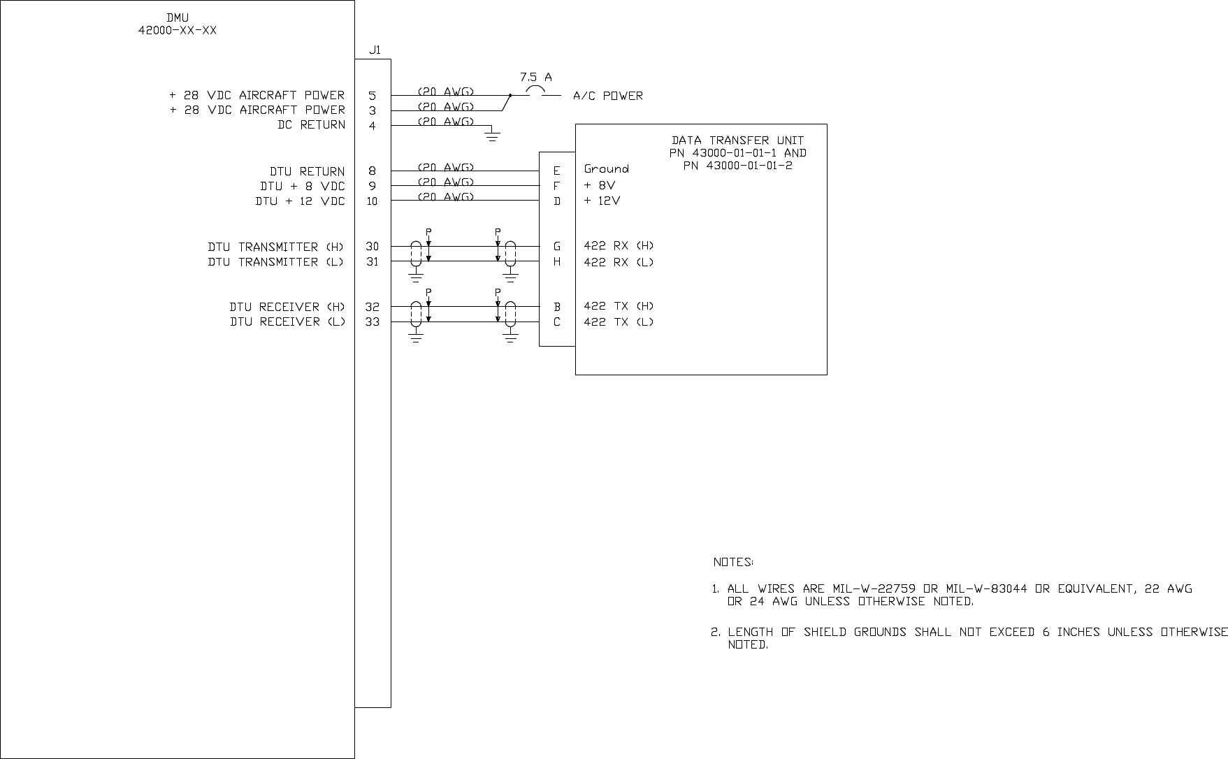
3-8 DMU TO DTU PN 43000-01-01-1 AND PN 43000-01-01-2 3-17
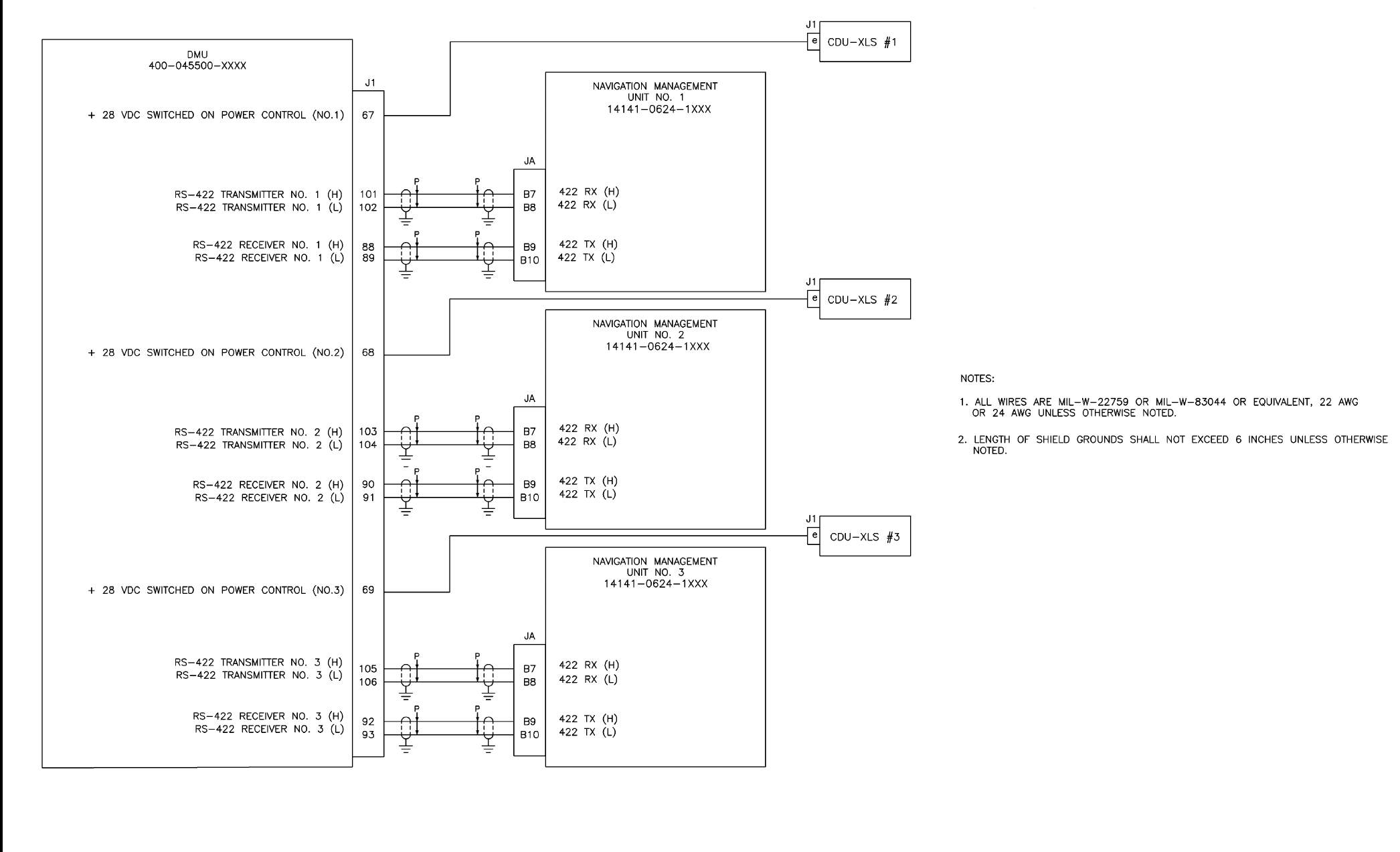
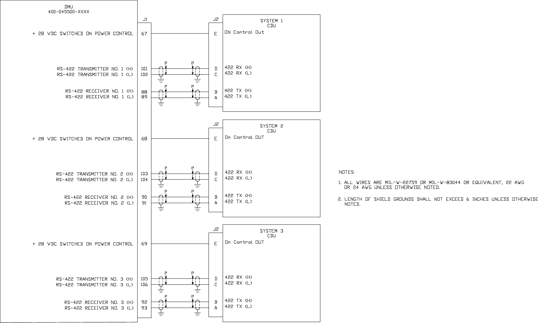
3-9 DMU TO NMU GNS-X 3-19
3-9A CDU-XLS TO AFIS INTERFACE 3-33
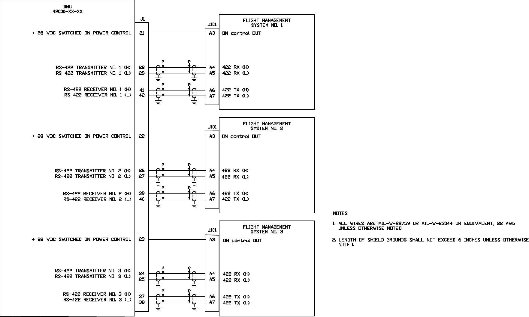
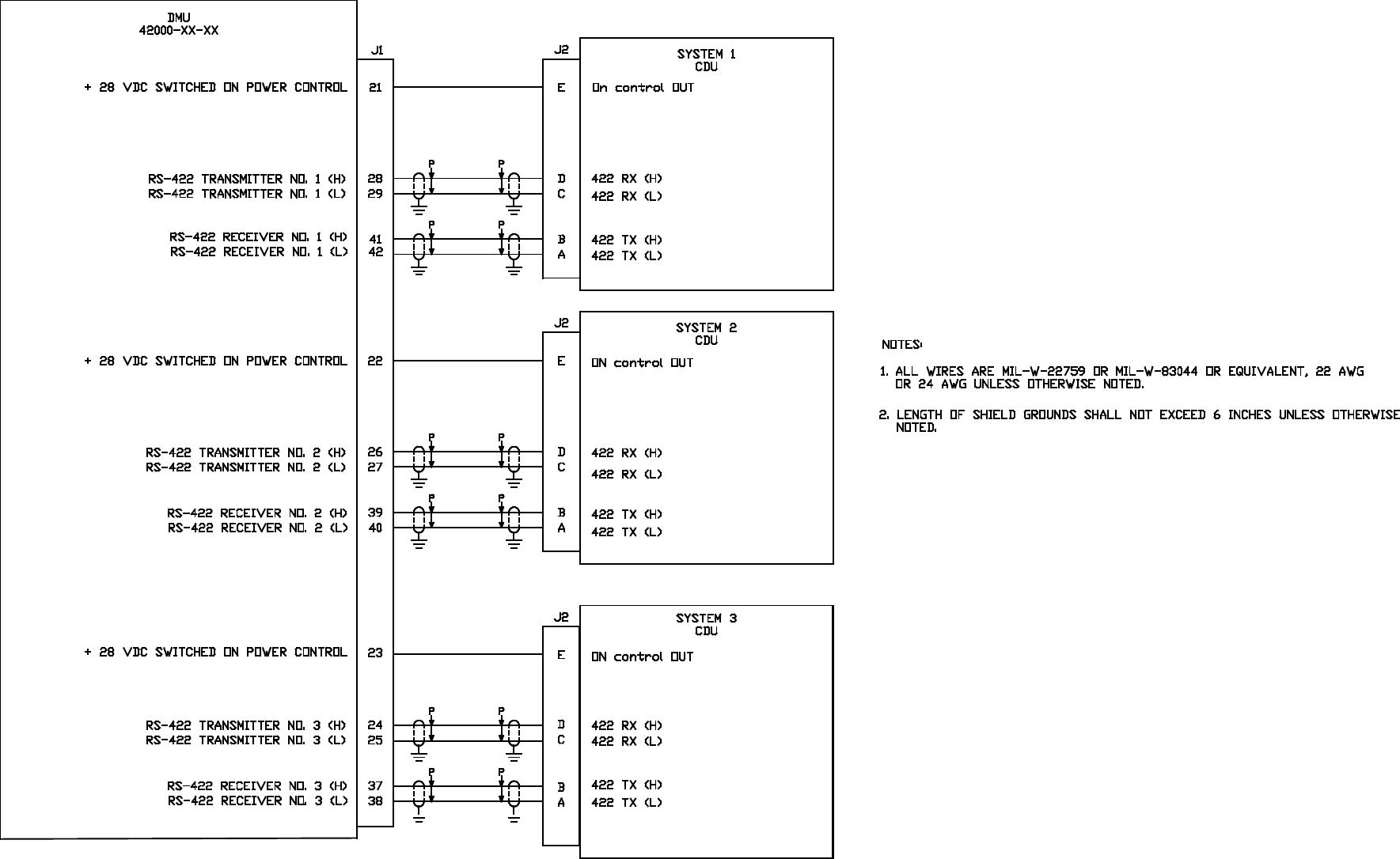
3-10 DMU TO FMC GNS-500A SERIES 4/5 3-37
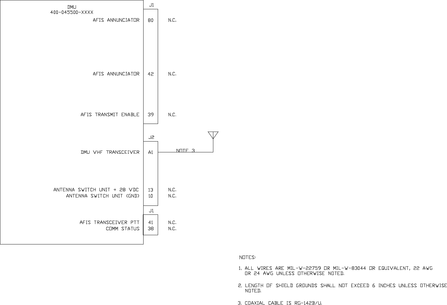
3-11 DMU TO SWITCHED AFIS ANTENNA 3-39
3-12 DMU TO DEDICATED AFIS ANTENNA 3-41
3-13 DMU TO PRINTERS AND TERMINALS 3-43
3-14 DMU TO CONFIGURATION MODULE AND SATFONE SYSTEM 3-45
3-15 DMU TO SCU 3-47
3-16 DISCRETE WIRING 3-51
3-17 DMU FUEL FLOW WIRING USING ELDEC INDICATOR 3-53
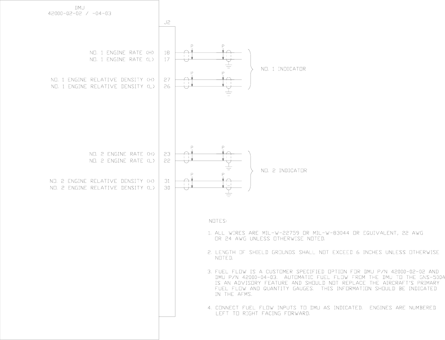
3-18 DMU FUEL FLOW WIRING FOR VARIOUS INDICATORS 3-55
3-19 DMU FUEL FLOW INTERTECHNIQUE 3-57
3-20 DMU FUEL FLOW GE 5 VRMS AC 3-59
3-21 DMU FUEL FLOW USING ELDEC TRANSMITTER AS SOURCE 3-61
3-22 DMU TO TRIPLE PORT DTU PN 15655-XXXX 3-63
3-23 DMU TO DTU PN 43000-01-01-3 AND PN 43000-01-01-4 3-65
3-24 DMU TO DTU PN 43000-01-01-1 AND PN 43000-01-01-2 3-67
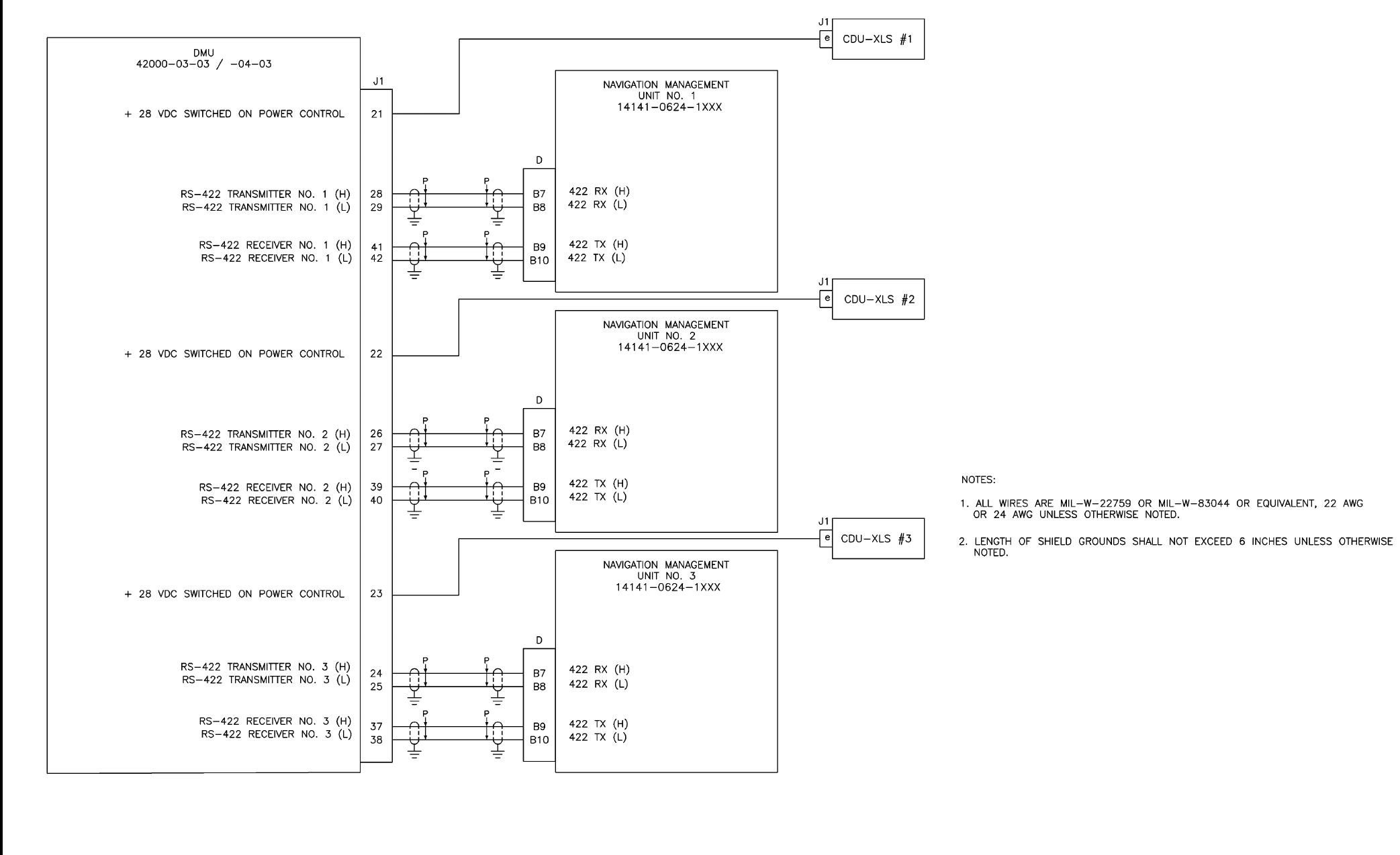
3-25 DMU TO FMC GNS-1000 3-69
3-26 DMU TO GNS-500A SERIES 4 3-77
3-27 DMU TO SWITCHED AFIS ANTENNA 3-79
3-28 DMU TO DEDICATED AFIS ANTENNA 3-81
3-29 DMU TO PRINTERS AND TERMINALS 3-83
3-30 DMU TO CONFIGURATION MODULE 3-85
3-31 DMU TO SCU 3-87
3-32 DMU TO ARNAV RPU AND GNS-XLS WIRING DIAGRAM 3-91
3-32A DMU TO FLIGHT DATA ACQUISITION AND MANAGEMENT SYSTEM 3-93
3-32B DMU TO 739 MCDU 3-95
3-33 DMU CONNECTOR PN 400-045500-XXXX 3-97
3-34 DMU CONNECTOR PN 42000-XX-XX 3-102
3-35 DTU CONNECTOR PIN ASSIGNMENT PN 43000-01-01-1 AND -2 3-105
3-36 DTU CONNECTOR PIN ASSIGNMENT PN 43000-01-01-3 AND -4 3-106
3-37 DMU J201 PIN ASSIGNMENT 3-107
3-38 CONFIGURATION MODULE CONNECTION 3-108
3-39 ANTENNA SWITCHING UNIT PIN ASSIGNMENT 3-109
3-40 TRIPLE PORT DTU CONNECTOR PIN ASSIGNMENT PN 15655-0X01 3-110
3-41 SCU UNIT CONNECTOR 3-111
3-42 REMOTE PROCESSOR UNIT (RTU) MATING CONNECTOR 3-113
3-43 CONNECTORS USED 3-114

Global
AIRBORNE FLIGHT INFORMATION SYSTEM
IMAFISJWA RR-1
March/2001
RECORD OF REVISIONS
REV.
NO.
REVISION
DATE
DATE
INSERTED BY REV.
NO.
REVISION
DATE
DATE
INSERTED BY
1 03/01/88
2 06/01/88
3 04/01/89
4 10/01/92
5 05/94
6 06/95
7 01/98
8 10/98
9 03/2000
10 05/2000
11 03/2001

Global
AIRBORNE FLIGHT INFORMATION SYSTEM
IMAFISJWA RR-2
March/2001
RECORD OF REVISIONS (cont.)
REV.
NO.
REVISION
DATE
DATE
INSERTED BY REV.
NO.
REVISION
DATE
DATE
INSERTED BY

Global
AIRBORNE FLIGHT INFORMATION SYSTEM
IMAFISJWA 1-1
March/2001
SECTION 1
GENERAL INFORMATION
1.1 INTRODUCTION
This manual contains information relative to the physical, mechanical and electrical characteristics
of the Global AFIS unit. General system installation information is also included.
1.2 EQUIPMENT DESCRIPTION
The Airborne Flight Information System (AFIS) consists of the following aircraft components: Data
Management Unit, Antenna Switching Unit (optional), Data Transfer Unit (optional), Satellite
Communication Unit (optional), High Power Amplifier/Low Noise Amplifier (optional), Satellite
Antenna (optional), Configuration Module and ARNAV MFD5115 RPU (optional).
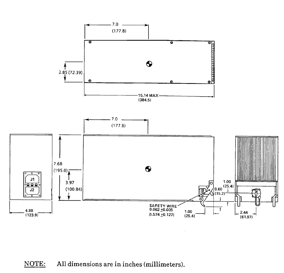
1.2.1 Data Management Unit (see Table 1-10)
The Data Management Unit (DMU) is a standard 1/2 ATR short unit. The DMU formats data
received from the DTU, VHF network or Satellite network. The DMU formats data for sending to
the ground from the aircraft using the VHF or Satellite network. The data is presented to the flight
management system interfaced to the DMU for display on a CRT/CDU. The DMU incorporates a
data quality VHF transceiver. The transceiver is tuned automatically by the DMU to use the
appropriate VHF ground station for the purpose of transmitting data to and receiving data from the
Global Data Center while in flight. The DMU can select between the VHF data network and a
satellite network automatically if the DMU is connected to a satellite network. The DMU is capable
of interfacing with one to six flight management systems. The DMU can be interfaced to two
printers as well as two personal computers.
1.2.2 Antenna Switching Unit (44000-1)
The Antenna Switching Unit (ASU) is a small box that is required for those installations where the
DMU VHF transceiver is to share an existing VHF communication antenna. The ASU contains
switching circuitry which allows the DMU transceiver to share a common antenna with an external
VHF communication transceiver. In receive mode both receivers are connected to the antenna. In
transmit mode, only one of the transmitters is connected to the antenna at any one time. The ASU
switches the transmit side of the antenna between the DMU data transmitter and the voice
transmitter. Pressing the AFIS annunciator on the instrument panel switches the transmit side of
the antenna to the DMU transmitter. Pressing the annunciator again or pressing the “push-to-talk”
button on the VHF communication radio switches the transmit side of the antenna back to the
voice transmitter.
1.2.3 Data Transfer Unit (15655-0101 or 15655-0201)
The Data Transfer Unit (DTU) is a 3.5 inch micro floppy disk unit. It can be mounted on 5.75 inch
DZUS rails or bulkhead mounted with a tray. The DTU contains a microfloppy drive, drive
electronics and control logic. The DTU is used to read AFIS flight plans and weather from a disk
inserted in the DTU. The disk is read by the DTU and the data is transferred to the Data
Management Unit. A ground-to-air transmitted AFIS flight plan can also be written to a disk by the
DTU as the flight plan is received by the Data Management Unit. The DTU is optional. If a
customer does not choose to load information from the disk then the DTU is not required.

Global
AIRBORNE FLIGHT INFORMATION SYSTEM
IMAFISJWA 1-2
March/2001
1.2.4 Satellite Communication Unit (153-017311-01)
The Satellite Communication Unit (SCU) is an ATR rack mounted unit. The SCU incorporates a
satellite transceiver and instructions for transmitting to and receiving from the satellite “C” network.
The SCU also contains information which allows it to tune to the appropriate satellite operating
region automatically and to the appropriate ground station. The SCU is optional. If a customer
does not choose to use satellite “C” operation then the SCU is not required.
1.2.5 High Power Amplifier/Low Noise Amplifier (153-017310-01)
The High Power Amplifier/Low Noise Amplifier (HPA/LNA) amplifier is a bulkhead mounted unit.
The HPA/LNA amplifies transmitted and received satellite “C” information while minimizing noise
and is connected between the SCU and a Satellite antenna. The HPA/LNA is required if the SCU
is installed.
1.2.6 Satellite Antenna (121-017537-01)
The Satellite Antenna is designed to meet Inmarsat system specifications for satellite “C” system
operation and is required if the SCU and HPA/LNA are installed. The Satellite Antenna is
connected to the HPA/LNA.
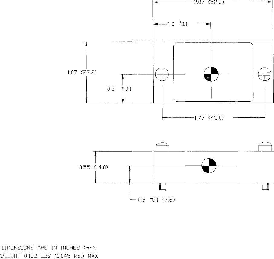
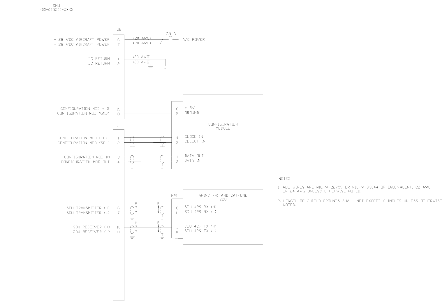
1.2.7 Configuration Module (31990-1)
The Configuration Module is mounted on the rack of the DMU. The Configuration module is a
nonvolatile memory that provides to the DMU, at power up, items that are related to the customer
aircraft such as tail number, aircraft basic operating weight, number of flight management systems
and selectable features such as on-off reporting, on-ground position reporting available to the
customer.
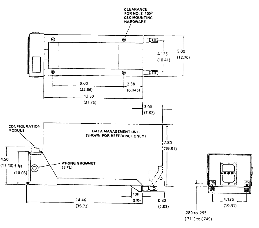
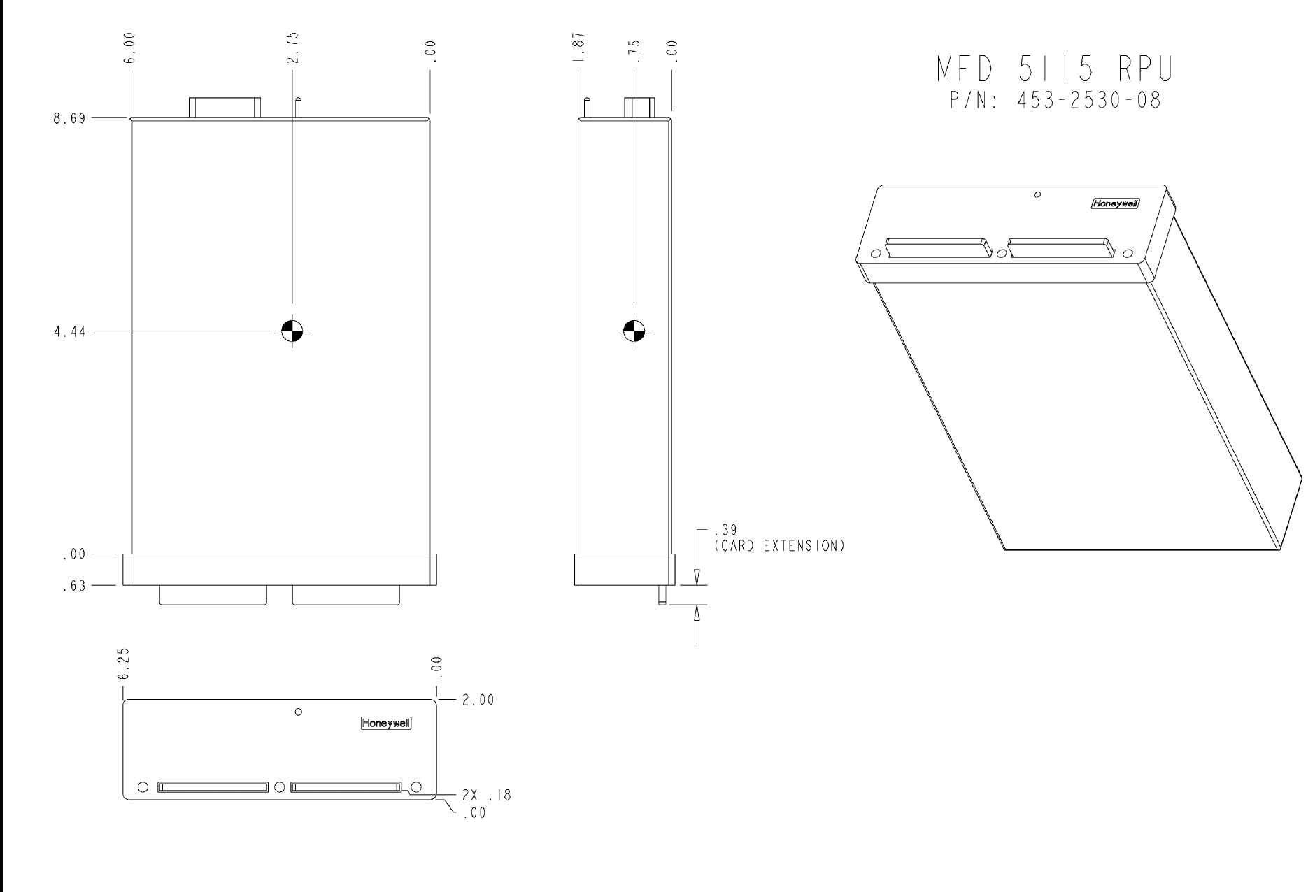
1.2.8 ARNAV MFD 5115 RPU (453-2530-08)
The ARNAV MFD 5115 RPU (Remote Processing Unit) is mounted in a frame assembly. The RPU
supplies AFIS™ weather graphical data to the GNS-XLS. If a customer does not choose to use
AFIS™ weather graphical data services then the RPU is not required.

Global
AIRBORNE FLIGHT INFORMATION SYSTEM
IMAFISJWA 1-3
March/2001
1.3 TECHNICAL CHARACTERISTICS
1.3.1 UNIT SPECIFICATIONS
DATA MANAGEMENT UNIT (DMU)
TSO COMPLIANCE: See Environmental Qualification Appendix
PHYSICAL DIMENSIONS: See Figure 2-1
TEMPERATURE: -55° C to +55° C
ALTITUDE: 55,000 feet
WEIGHT:
400-045500-0001,-0003,-0130,-0210,-0211
400-045500-0002,-0004
400-045500-0005,-2010,-2011
400-045500-0006
42000-01,02,03 (-) 01,02,03
42000-04-03
11.92 LBS. (5.89 KG.)
12.62 LBS. (6.23 KG.)
12.94 LBS. (6.39 KG.)
13.62 LBS. (6.73 KG.)
11.90 LBS. (5.89 KG.)
12.60 LBS. (6.22 KG.)
POWER REQUIREMENTS: 28 VDC
7.0 Amps Max - VHF Transmitter ON
2.0 Amps Max - VHF Transmitter OFF
SATELLITE COMMUNICATION UNIT (SCU)
TSO COMPLIANCE: FAA-PMA BEECH MODEL E-90
PHYSICAL DIMENSIONS: See Figure 2-12
TEMPERATURE: -25° C to +55° C
ALTITUDE: 25,000 feet above MSL
WEIGHT: 6.0 Lbs max (2.72 Kg)
POWER REQUIREMENTS: 27.5 VDC
6.7 Amps Max - Transmitter ON
1.0 Amps Max - Transmitter OFF

Global
AIRBORNE FLIGHT INFORMATION SYSTEM
IMAFISJWA 1-4
March/2001
DATA TRANSFER UNIT (DTU)
TSO COMPLIANCE: See Environmental Qualification Appendix
PHYSICAL DIMENSIONS: See Figure 2-5
TEMPERATURE: -55° C to +55° C
ALTITUDE: 55,000 feet
WEIGHT: 3.0 Lbs max (1.36 Kg)
POWER REQUIREMENTS: 28 VDC
1.0 Amps Max
ANTENNA SWITCHING UNIT (ASU)
TSO COMPLIANCE: See Environmental Qualification Appendix
PHYSICAL DIMENSIONS: See Figure 2-11
TEMPERATURE: -55° C to +55° C
ALTITUDE: 55,000 feet
WEIGHT: 1.3 Lbs max (0.59 Kg)
POWER REQUIREMENTS: 28 VDC
0.8 Amps Max

Global
AIRBORNE FLIGHT INFORMATION SYSTEM
IMAFISJWA 1-5
March/2001
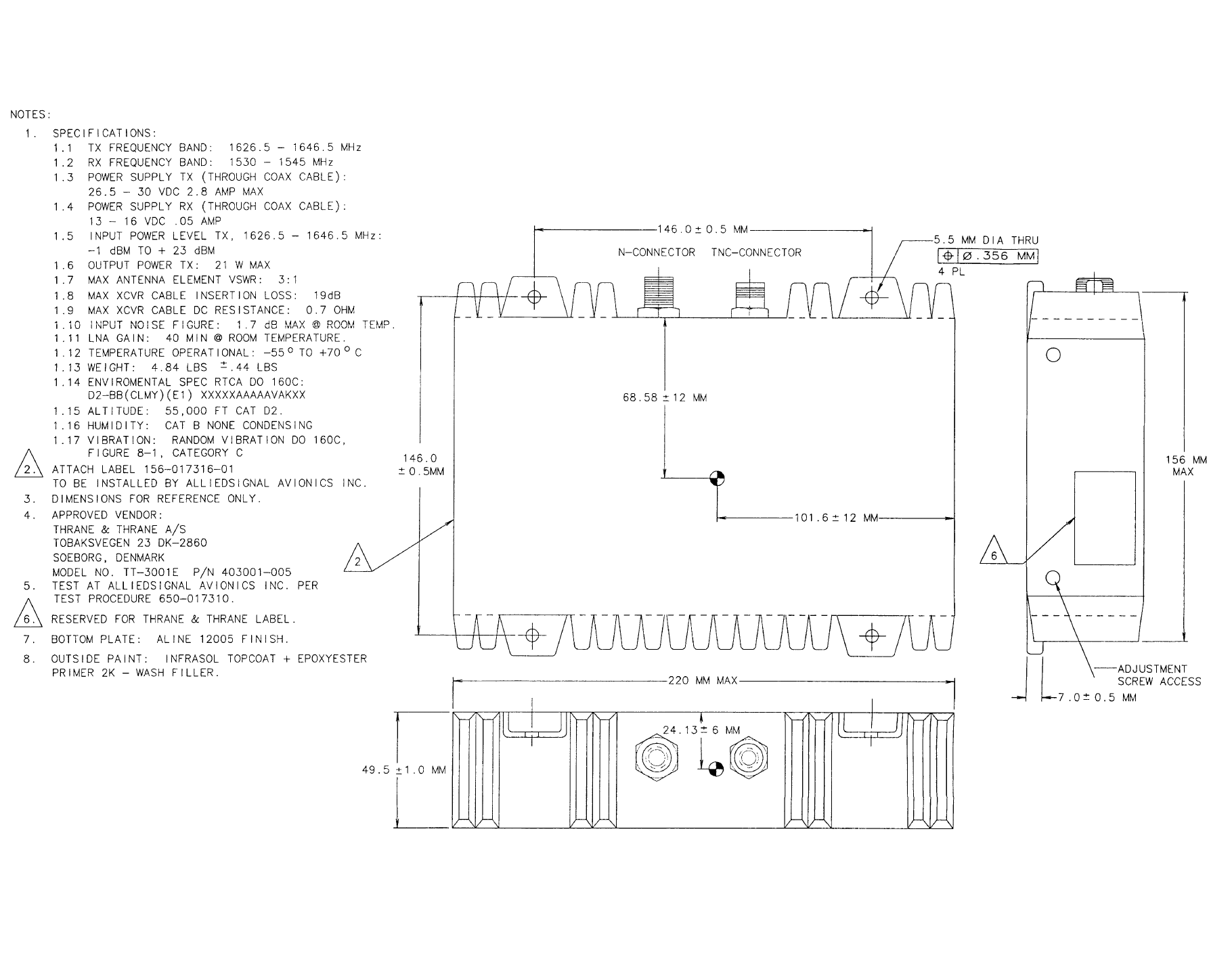
HIGH POWER AMPLIFIER / LOW NOISE AMPLIFIER (HPA/LNA)
TSO COMPLIANCE: FAA-PMA BEECH MODEL E-90
PHYSICAL DIMENSIONS: See Figure 2-14
TEMPERATURE: -55° C to +70° C
ALTITUDE: 55,000 feet
HUMIDITY: CAT B Noncondensing
VIBRATION: Random Vibration CAT C
WEIGHT: 4.84 ± 0.44 Lbs (2.18 Kg)
POWER REQUIREMENTS:
TX (through coax cable)
RX (through coax cable)
26.5 - 30.0 VDC, 2.8 Amps Max
13 - 16 VDC, 0.05 Amps Max
FREQUENCY:
TX BAND
RX BAND
1626.5 - 1646.5 MHz
1530 -1545 MHz
VSWR: 3:1 maximum
INPUT POWER TX: -3 to +20dBm (1626.5 - 1646.5 MHz)
OUTPUT POWER TX: 21 WATTS maximum
LNA GAIN: 42 - 49 dB
CONFIGURATION MODULE
TSO COMPLIANCE: See Environmental Qualification Appendix
PHYSICAL DIMENSIONS: See Figure 2-4
TEMPERATURE: -55° C to +55° C
ALTITUDE: 55,000 feet
WEIGHT: 0.102 Lbs (0.045 Kg) max
POWER REQUIREMENTS: Supplied by DMU

Global
AIRBORNE FLIGHT INFORMATION SYSTEM
IMAFISJWA 1-6
March/2001
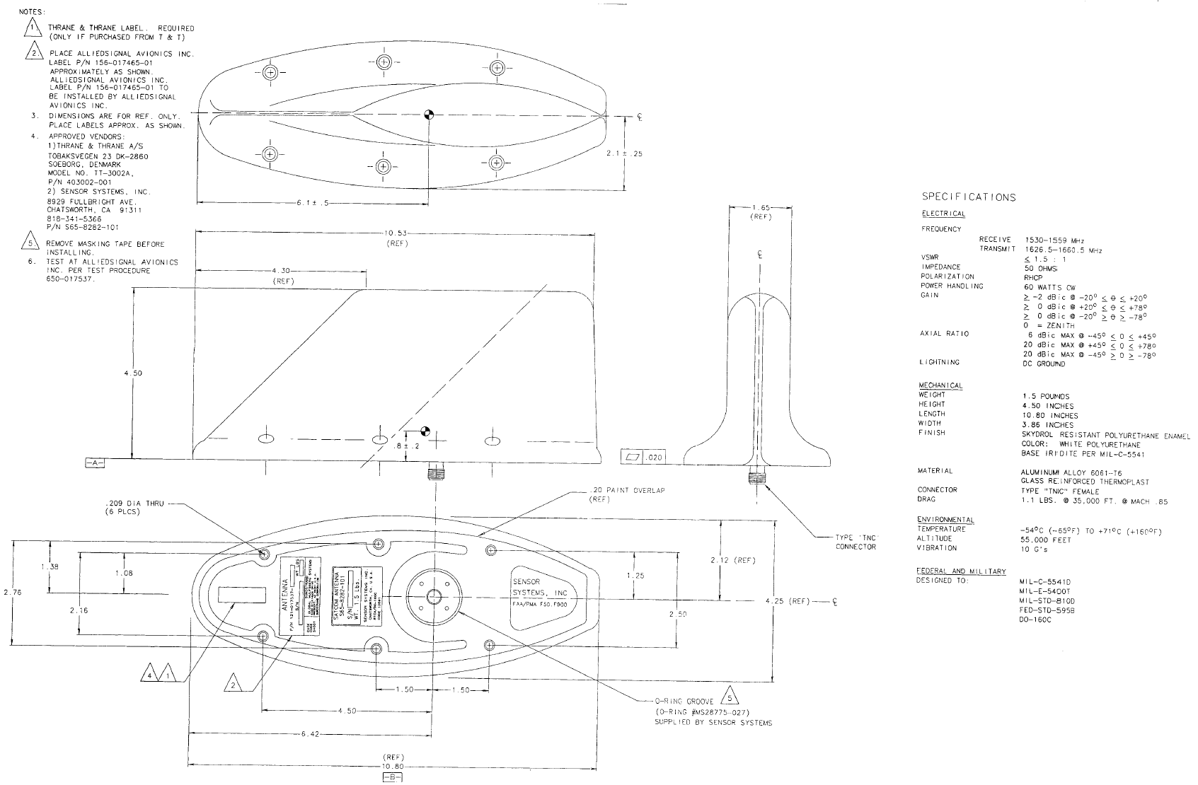
LOW PROFILE JET BLADE ANTENNA
TSO COMPLIANCE: FAA-PMA Unit - Sensor Systems, Inc. PMA
Holder
PHYSICAL DIMENSIONS: See Figure 2-15
TEMPERATURE: -54° C to +71° C
ALTITUDE: 55,000 feet
WEIGHT: 1.5 Lbs max (0.68 Kg)
POWER HANDLING: 60 WATTS CW
FREQUENCY:
TX BAND
RX BAND
1626.5 - 1660.5 MHz
1530 -1559 MHz
VSWR: < 1.5: 1
POLARIZATION: RHCP
IMPEDANCE: 50 ohms
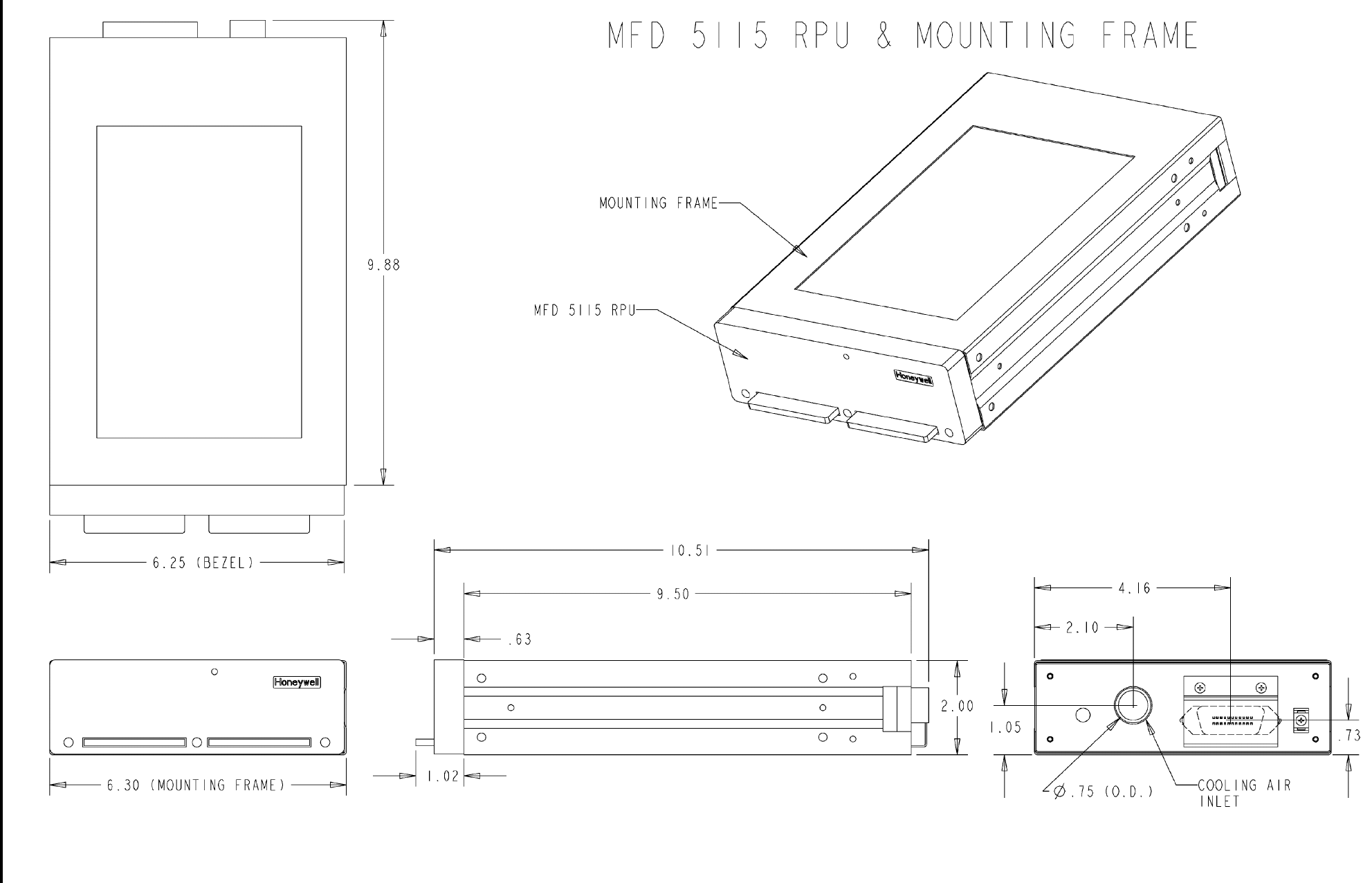
REMOTE PROCESSING UNIT (RPU)
TSO COMPLIANCE: TSO Unit - ARNAV Systems Inc. TSO Holder
PHYSICAL DIMENSIONS:
Height
Width
Depth
2.0 inches (50.8 mm)
6.25 inches (159 mm)
9.25 inches (235 mm)
TEMPERATURE: -20° C to +70° C
ALTITUDE: 50,000 feet
WEIGHT: 2.5 Lbs (1.15 Kg)
POWER REQUIREMENTS: 27.5 Vdc at 750 mA

Global
AIRBORNE FLIGHT INFORMATION SYSTEM
IMAFISJWA 1-7
March/2001
1.3.2 SYSTEM SPECIFICATIONS
The following pages of system characteristics provide details of the various interfaces for the
AFIS.
1.3.2.1 Fuel Flow Input (ANALOG INPUT)
NOTE:
Fuel Flow information is only applicable to DMUs PN 42000-02-02,
PN 42000-04-03, PN 400-045500-0002, PN 400-045500-0004, and
PN 400-045500-0006.
1.3.2.1.1 J.E.T. Fuel Flow System
NOTE:
This interface is provided by a modification to 54-1158-01 module
per J.E.T. SB number SB542-1158-7.
Table 1-1
Source LearJet volumetric flow rate transducer
Range See Table 1-1
Accuracy ± 0.5% of volume
Scale Factor Flow Rate = 28.125 x frequency
Where:
Flow Rate = Pounds Per Hour and Frequency = Hertz
Load 10K ohms minimum
Amplitude +9 volts, ground referenced
J.E.T. Range (PPH) Accuracy Scaling (PPH/V) Output
Impedance
Applicable to
J.E.T. SB
542-1158-7
0 to 2500 ± 0.5% of
volume
28.125 10K Ohms

Global
AIRBORNE FLIGHT INFORMATION SYSTEM
IMAFISJWA 1-8
March/2001
1.3.2.1.2 ELDEC Mass Flow Fuel System
Table 1-2
Source ELDEC Mass Flow Transducer
Signal Type Each sensor generates two AC signals.
Flow rate information is contained in the phase difference
between the two signals.
Range 150 to 2200 PPH
Amplitude 0.30 to 1.60 V P-P Drum Signal
0.30 to 1.60 V P-P Impeller Signal
Frequency 5.7 to 28 Hz
Phase Delay 0 to 55 msec
Scale Factor See Table 1-2
Load 200K ohms minimum
ELDEC SENSOR MODEL NUMBER TRANSMITTER SCALING (LB/HR/mS)
9-127-27
9-127-33
9-127-51
9-127-39
40
9-127-12 100
9-231-05 20

Global
AIRBORNE FLIGHT INFORMATION SYSTEM
IMAFISJWA 1-9
March/2001
1.3.2.1.3 ELDEC Mass Fuel Flow System
NOTE:
There are two types of indicator outputs: pulse width and DC
voltage. Some of the indicators have both. If this is the case the
pulse width output is preferred.
Pulse Width Output From Indicator
DC Rate Output Indicator
Source ELDEC Fuel Flow Indicator
Ty p e Ground referenced voltage pulse flow rate is proportional
to width.
Amplitude VOL = 0 ± 2 Volts
VOH = 12 ± 2 Volts
Indicator
Output
Impedance
15K ohms
Range/
Accuracy/
Impedance
See Table 1-3
Repetition
Time
36 to 175 msec
Source ELDEC Fuel Flow Indicator
Ty p e DC differential voltage proportions to fuel rate. The signal
low is 5.1 ± 1.0 Volts above the power ground. A refer-
ence voltage of 6.2 ± 0.32 VDC is provided by ELDEC,
but is unused by the GNS-500.
Signal
Range
0.0 to 5.5 VDC differential
Indicator
Output
Impedance
5K ohms each leg
Scaling/
Range/
Accuracy
See Table 1-3

Global
AIRBORNE FLIGHT INFORMATION SYSTEM
IMAFISJWA 1-10
March/2001
Table 1-3
1.3.2.1.4 AMETEK Indicator Fuel Flow
NOTE:
Flow rate is proportional to voltage
.
ELDEC
Indicator
Model No.
Aux
Pulse
Width
Aux
DC
Rate
Range
PPH
Scaling
Pulse
PPH/mS
DC
V/PPH
Accuracy
Pulse
DC
9-328-01 YES YES 0 to 2200 40 0.0025 ± 2 lb/hr ± 2%
9-328-10 YES YES 0 to 2200 40 0.0025 ± 2 lb/hr ± 2%
9-328-13 YES YES 0 to 3000 100 0.00167 ± 2 lb/hr ± 2%
9-328-17 YES N/A 0 to 2000 40 - - - ± 2 lb/hr - - -
9-328-26 YES - - - 0 to 4000 100 - - - ± 2 lb/hr - - -
9-328-19 YES YES 0 to 3300 100 0.00142 ± 2 lb/hr ± 2%
9-328-20 YES YES 0 to 4000 100 0.00143 ± 2 lb/hr ± 2%
9-394-01 YES TBD TBD 100 ± 2 lb/hr ± 2%
9-422-01 YES N/A 0 to 10000 80 ± 2 lb/hr ± 2%
9-464-02 YES YES 0 to 1000 40 TBD ± 2 lb/hr ± 2%
9-464-06 YES YES 0 to 1000 40 TBD ± 2 lb/hr ± 2%
9-464-09 N/A YES 0 to 1200 - - - TBD ± 2 lb/hr ± 2%
9-464-16 YES YES 0 to 1000 40 - - - ± 2 lb/hr ± 2%
9-464-25 YES YES 0 to 1200 40 .004166 ± 2 lb/hr ± 2%
9-464-41 YES YES 0 to 1200 40 .004166 ± 2 lb/hr ± 2%
Source Auxiliary flow rate output from AMETEK
Range 0 to 2400 PPH
Signal Type 0.5 to 5.5 VDC ground referenced
Scaling Flow Rate = 480 (Vsig - 0.5)
Where: Flow Rate = PPH, Vsig = Volts
Accuracy ± 50 mV

Global
AIRBORNE FLIGHT INFORMATION SYSTEM
IMAFISJWA 1-11
March/2001
1.3.2.1.5. Gull Indicator Fuel Flow - Model 360-954-XXX
NOTE:
Flow rate is proportional to voltage
.
1.3.2.1.6 General Electric 5v RMS AC Fuel Flow
NOTE:
Flow rate is proportional to RMS voltage.
Fuel flow - G.E. PN 8TJ64GBM-3
Fuel flow- G.E. PN 8TJ85GBA
Source Gull fuel flow indicator
Range 0 to 2000 PPH
Accuracy ± 3%
Signal Type 1.0 to 5.4 VDC differential
Scaling Flow Rate = 500 (vsig - 1.0)
Where: Flow Rate = PPH Vsig = VDC
Source Pick off type fuel flow transducer
Signal Type Signal 0 to 5 VRMS, 400 Hz differential signal
Range 0 to 4000 PPH
Scaling F = 800 (Vsig)
Where: F = Flow in PPH, Vsig = VRMS
Reference 115 VRMS nominal, 400 Hz aircraft power
Source G.E. AC Fuel Flow Transmitter
Signal Type Signal 0 to 5 VRMS, 400 Hz differential signal
Range 400 to 12,500 PPH
Motor
Frequency
8 cycles per second
Scale Factor F = 2400 (Vsig)
Where: F = Flow in PPH, Vsig = VRMS
Reference 115 VRMS nominal, 400 Hz aircraft power

Global
AIRBORNE FLIGHT INFORMATION SYSTEM
IMAFISJWA 1-12
March/2001
Fuel flow - G.E. PN 8TJ85GAT
1.3.2.1.7 IDC Indicator Fuel Flow
NOTE:
Auxiliary fuel flow rate output from an IDC fuel flow indicator. Some
models have pulse width outputs, DC voltage outputs or both. The
use of the pulse width output is preferred.
Pulse Width Output Signal From Indicator
(Flow rate is proportional to pulse width.)
Source G.E. AC Fuel Flow Transmitter
Signal Type Signal 0 to 5 VRMS, 400 Hz differential signal
Range 400 to 12,500 PPH
Motor
Frequency
8 cycles per second
Scale Factor F = 2400 (Vsig)
Where: F = Flow in PPH, Vsig = VRMS
Reference 115 VRMS nominal, 400 Hz aircraft power
Ty p e Ground referenced voltage pulse
Amplitude VOL = 0V, VOH = 5V
Output
Impedance
for Indicator
10K Ohm pull-up
Repetition
Time
100 to 500 msec
Range/
Accuracy/
Scaling
See Table 1-4

Global
AIRBORNE FLIGHT INFORMATION SYSTEM
IMAFISJWA 1-13
March/2001
DC Rate Output from Indicator
Table 1-4
Ty p e DC Differential Voltage proportional to fuel rate
Signal
Range
0 to 4.0 VDC
Output
Impedance
200 Ohms on each leg
Range/
Accuracy/
Scaling
See Table 1-4
IDC
Indicator
Model No.
Aux
Pulse
Width
Aux DC
Rate
Range
PPH
Scaling
Pulse
PPH/mS
DC
V/PPH Accuracy
31653-003 YES - - - 0 to 8000 80 - - - ± 20 PPH
31653-004 YES - - - 0 to 8000 80 - - - ± 20 PPH
31653-013 YES YES 0 to 8000 80 0.0005 ± 20 PPH
31653-014 YES YES 0 to 8000 80 0.0005 ± 20 PPH
37804-001 YES - - - 0 to 8000 80 - - - ± 20 PPH
37804-002 YES - - - 0 to 8000 80 - - - ± 20 PPH
37804-011 YES - - - 0 to 8000 80 - - - ± 20 PPH
37804-012 YES - - - 0 to 8000 80 - - - ± 20 PPH
37804-101 YES YES 0 to 8000 80 0.0005 ± 20 PPH
37804-102 YES YES 0 to 8000 80 0.0005 ± 20 PPH

Global
AIRBORNE FLIGHT INFORMATION SYSTEM
IMAFISJWA 1-14
March/2001
1.3.2.1.8 RAGEN Data Systems Fuel Flow
NOTE:
RAGEN Data Systems also manufactures fuel systems formerly
manufactured by Consolidated Airborne and Bendix. Flow rate is
proportional to Voltage.
Table 1-5
1.3.2.1.9 Canadian Marconi Fuel Flow System
NOTE:
DC voltage output in which the voltage is proportional to the flow rate.
Source Fuel Flow Rate Signal from fuel flow transducer
Signal Type DC Voltage Output
Output
Impedance
See Table 1-5
Range/
Accuracy/
Scaling
See Table 1-5
RAGEN
Model
Range
(PPH) Accuracy Scaling
(PPH/V)
Output
Impedance
3268-005 0 to 1800 TBD 283.688 TBD
3268-014 0 to 1800 TBD 283.114 TBD
3268-011 0 to 500 TBD 100.000 TBD
Source Auxiliary Fuel Flow Rate Signal From Indicator
Signal Type DC Voltage Output
Output
Impedance
1K Ohms
Range/
Accuracy/
Scaling
See Table 1-6

Global
AIRBORNE FLIGHT INFORMATION SYSTEM
IMAFISJWA 1-15
March/2001
Table 1-6
1.3.2.1.10 Aero Systems Fuel flow System
NOTE:
Signal frequency is proportional to fuel flow rate.
Table 1-7
Canadian Marconi
Model No. Range (PPH) DC Scaling
(PPH/V) Accuracy
418-107-103 0 to 4500 900 ±2%
418-107-104 0 to 4500 900 ± 2%
Source Aero Systems Model DD-4000-004 Magneson Fuel Flow
Signal Convertor. The DD-4000 converts G.E. Second
Harmonic flow signals to a frequency proportional to fuel
rate for a maximum of four engines
Signal
Range
0 to 2500 Hz
Signal
Levels
High side of signal switches between 7.5V and 15.0V
whereas the low side is 7.5V above ground.
Output
Impedance
2 Kohms pull up to +15V.
Transistor switch to 7.5V.
Range/
Accuracy/
Scaling
See Table 1-7
Aero Systems
Model No.
Range
(PPH)
Scaling
(PPH/Hz) Remarks
DD-4000-004 0 to 2300 0.92 DD-4000-004 is only the
0 to 3000 1.200 convertor model number.
0 to 4000 1.600 The scaling, however is
0 to 8000 3.200 custom calibrated for
0 to 12000 4.800 each aircraft.
0 to 14000 5.600

Global
AIRBORNE FLIGHT INFORMATION SYSTEM
IMAFISJWA 1-16
March/2001
1.3.2.1.11 Intertechnique Fuel flow System
NOTE:
Flow rate is proportional to frequency; the fuel relative density signal
is a 3 to 5 VDC signal proportional to the fuel specific gravity
(relative density).
1.3.2.2 RS-422A Serial Data Input
1.3.2.2.1 Data Transfer Unit (DTU)
Source Intertechnique totalizer amplifier indicator Models
723-161-1 and 723-161-2. The signals from the indicators
are input to the totalizer.
Range
Reference
0 to 2000 PPH
Scaling Flow = [Vsig/5.0] x 34.506 x frequency
Where: Flow is PPH, Vsig = Voltage of density signal and
Freq = Frequency of rate signal
Signal: Frequency:
Density:
VOL = 0.7 ±TBD V
VOH = 12.0 ±TBD V
Pulse width = 2.5 ±TBD V
Impedance Output = 270 ohms
Range = 3 to 5.0 VDC
Output Impedance = 3.9 Kohms
Data Type Both transmit and receive data are two-wire, balanced
voltage digital signals in accordance with EIA RS-422A
electrical format.
Receive
Logic Level
Logic 1: +2 to +6V differential
Logic 0: -2 to -6V differential
Data Rate 22.5 KBS
Bit Stream
Format
Asynchronous with 1 start bit, 8 bits of data and 2 stop
bits between words.
Word Type 8 bit with no parity

Global
AIRBORNE FLIGHT INFORMATION SYSTEM
IMAFISJWA 1-17
March/2001
1.3.2.2.2 Satellite Communications Unit (SCU)
NOTE:
The following information is only applicable to DMUs P/N
42000-03-03, 42000-04-03, 400-045500-0003, 400-045500-0004,
400-045500-0130, 400-045500-0210, 400-045500-0211,
400-045500-2010, and 400-045500-2011.
SAT 422 Receive
SAT 422 CONTROL IN
Data Type Receive data is a two-wire balanced voltage digital sig-
nals in accordance with EIA RS-422A electrical format.
Receive
Logic Level
Logic 1: +2 to +6V differential
Logic 0: -2 to -6V differential
Data Rate 4800 bit per second
Bit Stream
Format
Asynchronous with 1 start bit, 8 bits of data and 1 stop bit
between words.
Word Type 8 bit with no parity
Data Type CONTROL IN is a two-wire balanced voltage digital
signal in accordance with EIA RS-422A electrical format.
CONTROL IN
Logic Level
Logic 1: +2 to +6V differential
Logic 0: -2 to -6V differential
Data Rate Changes on software conditions, indicates the current
state of the SCU for receiving data from DMU
Data Level ON (high): SCU ready to receive data from DMU
OFF (low): SCU not ready to receive data from DMU

Global
AIRBORNE FLIGHT INFORMATION SYSTEM
IMAFISJWA 1-18
March/2001
1.3.2.3 ARINC 429 INPUT - (See Tables 1-8A and 1-8B)
NOTE:
The following information is only applicable to DMU PN 400-045500-XXXX.
ARINC 429 Digital Input Navigational System
Table 1-8A
NOTE:
The following table is only applicable to DMUs PN 400-045500-0005,
400-045500-0006, 400-045500-2010, and 400-045500-2011.
Data Type 2 wire serial data meeting ARINC 429 characteristics
Logic State Logic 1: > 5V differential, +6.5 to +13 V
Logic 0: < 5V differential, -6.5 to -13 V
NULL: 0 V differential
Data Rate Changes on software conditions, indicates the current
state of the SCU for receiving data from DMU
Format 32 bit word, including 1 parity bit Return-To-Zero (RZ)
format with at least 4 nulls between words.
NAME LABEL DATA RATES
ISO Alphabet #5 Messages 357 SPECIAL
GMT 125 0.1 Sec
Baro Corrected Altitude 204 0.0625 Sec
True Airspeed 210 0.125 Sec
Static Air Temperature 213 0.5 Sec
DATE 260 1.0 Sec
Present Position Latitude 310 0.2 Sec
Present Position Longitude 311 0.2 Sec
Groundspeed 312 0.04 Sec
Wind Speed 315 0.1 Sec
Wind Direction 316 0.1 Sec

Global
AIRBORNE FLIGHT INFORMATION SYSTEM
IMAFISJWA 1-19
March/2001
ARINC 429 Digital Input Satellite and SATFONE System
Table 1-8B
1.3.2.4 ANALOG OUTPUTS (DMU)
1.3.2.4.1 Valid Discretes DTU and DMU
1.3.2.4.2. PTT Line
Ground (50 ohms or less between PTT line and DC ground) turns the transmitter ON. Open
(50,000 ohms or more between PTT line and DC ground) turns the transmitter OFF.
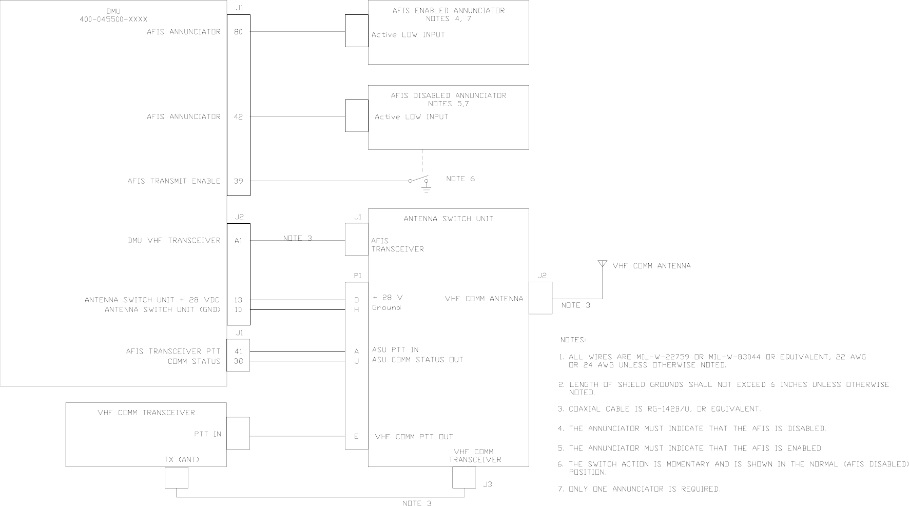
1.3.2.4.3. AFIS Annunciator
NOTE:
The following information is only applicable to DMU PN
400-045500-XXXX installations using the Antenna Switching Unit.
NAME LABEL DATA RATES
ISO Alphabet #5 Messages 304 SPECIAL
SDU System Status 270 1.0 Sec
Data Type Indicates system is operating
Logic State Ground (<10 ohms) indicates a valid output
Open (>1M ohm) indicates an invalid output
Response
Time
1.0 ± 0.5 seconds valid to invalid
2.5 ± 0.5 seconds invalid to valid
Current Load 250 mA
Logic State DMU J1 pin 42: Ground (<10 ohms) indicates AFIS is Disabled
Open (> 1 M ohm) indicates AFIS is Enabled
DMU J1 pin 80: Ground (<10 ohms) indicates AFIS is Enabled
Open (> 1 M ohm) indicates AFIS is Disabled
Signal Type Level
Current Capacity .5 Amp Maximum

Global
AIRBORNE FLIGHT INFORMATION SYSTEM
IMAFISJWA 1-20
March/2001
1.3.2.5 RS-422A SERIAL DIGITAL OUTPUTS (DMU)
1.3.2.5.1 Data Transfer Unit (DTU)
1.3.2.5.2 Satellite Communications Unit (SCU)
NOTE:
The following information is only applicable to DMUs PN 42000-03-03,
42000-04-03, 400-045500-0003, 400-045500-0004, 400-045500-0130,
400-045500-0210, 400-045500-0211, 400-045500-2010 and
400-045500-2011.
SAT 422 Transmit
Data Type Both transmit and receive data are two-wire balanced digital signals in
accordance with EIA RS-422A electrical format.
Transmit Logic Level Logic 1: +2V to +6V differential
Logic 0: -2V to -6V differential
Data Rate 22.5 KBS
Bit Stream Format Asynchronous with 1 start bit, 8 bits of data and 2 stop bits between
words.
Word Type 8 bit with no parity
Data Type Transmit data is a two-wire balanced voltage digital signal in accordance
with EIA RS-422A electrical format.
Transmit Logic Level Logic 1: +2V to +6V differential
Logic 0: -2V to -6V differential
Data Rate 4800 bits per second
Bit Stream Format Asynchronous with 1 start bit, 8 bits of data and 1 stop bit between
words.
Word Type 8 bit with no parity

Global
AIRBORNE FLIGHT INFORMATION SYSTEM
IMAFISJWA 1-21
March/2001
SAT 422 CONTROL OUT
SAT NAV DATA 422 Transmit
1.3.2.6 ARINC 429 OUTPUTS (See tables 1-9A & B)
NOTE:
The following information is only applicable to DMU Part Number
400-045500-XXXX.
Data Type CONTROL OUT is a two-wire balanced voltage digital signal in
accordance with EIA RS-422A electrical format.
CONTROL OUT
Logic Level
Logic 1: +2V to +6V differential
Logic 0: -2V to -6V differential
Data Rate Changes on software conditions, indicates the current state of the
DMU for receiving data from SCU.
Data Level ON (high): The DMU is ready to receive data from SCU
OFF (low): The DMU is not ready to receive from SCU.
Data Type Transmit data is a two-wire balanced voltage digital signal in accordance
with EIA RS-422A electrical format.
Transmit
Logic Level
Logic 1: +2V to +6V differential
Logic 0: -2V to -6V differential
Data Rate 4800 bits per second
Bit Stream
Format
Asynchronous with 1 start bit, 8 bits of data and 1 stop bit between words.
Stream of data appears once a second if satellite configured and present
position information available.
Word Type 8 bit with no parity
Data Type 2-wire serial data meeting electrical characteristics of ARINC 429
Logic State Logic 1: + 10 ± 1 V differential balance to ground
Logic 0: - 10 ± 1 V differential balance to ground
NULL: ± 2.5 V differential
Data Rate 12.5 KBS
Format 32 bit word including 1 parity bit, Return-to-Zero (RZ) format with a least
4 nulls between words.

Global
AIRBORNE FLIGHT INFORMATION SYSTEM
IMAFISJWA 1-22
March/2001
ARINC 429 Digital Output
Table 1-9A
NOTE:
The following table is applicable to DMUs PN 400-045500-0005,
400-045500-0006, 400-045500-2010 and 400-045500-2011.
ARINC 429 Digital Output Satellite & SATFONE System
Table 1-9B
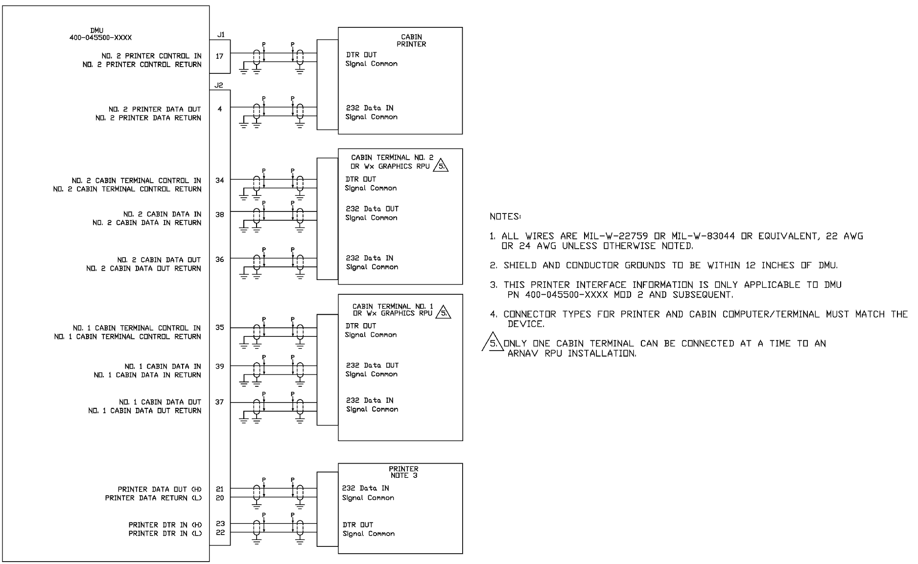
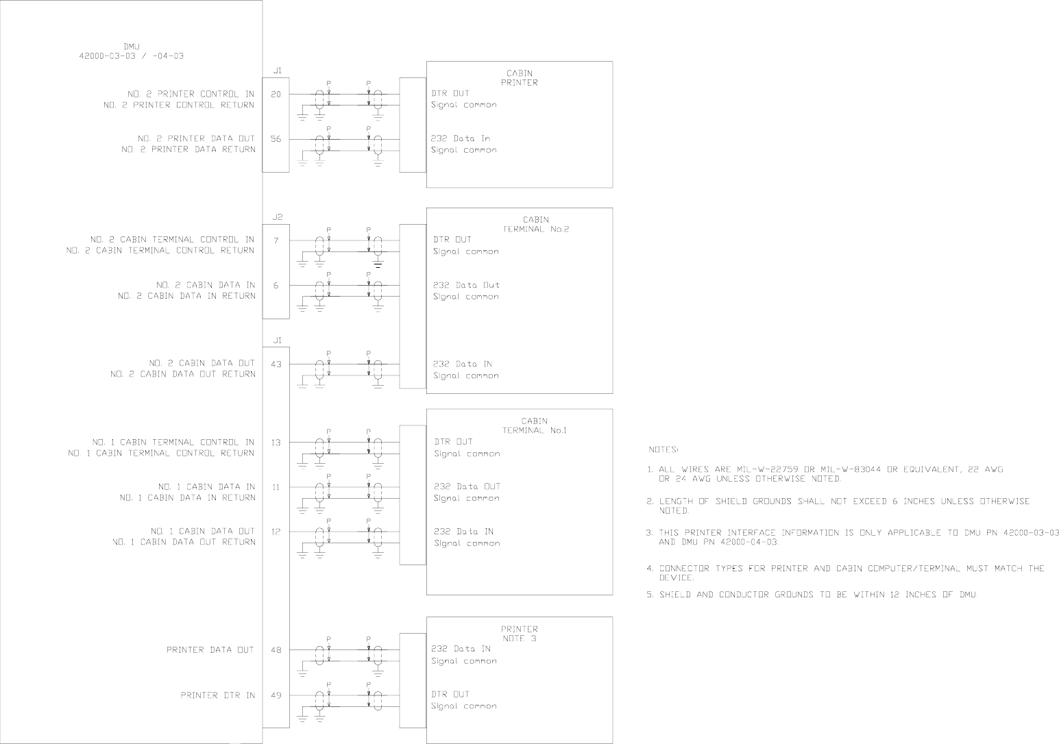
1.3.2.7 Printer Interface
NOTE:
Four signal lines are required between the AFIS DMU and the
printer: Printer Serial Data Out, Printer Serial Data Return, Printer
DTR (Data Terminal Ready) IN, and Printer DTR return.
1.3.2.7.1 Printer Serial Data Out
NAME LABEL DATA RATES
AFIS System Status 270 SPECIAL
AFIS Data Status 271 SPECIAL
Fuel Flow - Engine 347 0.1 Sec
ISO Alphabet #5 message 357 SPECIAL
NAME LABEL DATA RATES
AFIS System Status 270 1.0 Sec
ISO Alphabet #5 message 307 SPECIAL

Global
AIRBORNE FLIGHT INFORMATION SYSTEM
IMAFISJWA 1-23
March/2001
1.3.2.7.2 Printer Serial Data Return
Electrical
Direction
RS-232C electrical characteristics. Two wire system.
Data from DMU to printer.
Signal Format Asynchronous, serial transmission. 11 bit times comprised of
1 start bit, 8 data bits, and 2 stop bits.
8 data bits defined by ASCII character set.
No parity bit
Order of Bit Transmission First bit is start bit, followed by least significant data bit,
followed by remaining 7 data bits, followed by 2 stop bits.
Data Rate 1200 bits per second
Data Stream 1 - 80 printable characters transmitted
Carriage return (CR) and linefeed (LF) are transmitted
following the last printable character.
File Structure File contains 1 - 4000 printable characters (hexadecimal 20 -
7E), CR characters (hexadecimal 0D), and LF characters
(hexadecimal 0A).
Control character, ETX (hexadecimal 03), is sent as last
character of a file transmission to indicate that the file is
completed and can be used for printer buffer control.The
printer may ignore the ETX character if buffer control is not
needed.
A CR and LF is transmitted at the beginning of each new file.
The file is transmitted in groups of 80 characters or less with a
CR character and a LF character following each group of 80
characters or less.
The printer must be capable of printing 80 columns or have
auto wrap so that the 80 characters can be printed without
including the CR and LF characters until the end of the 80
character or less transmission.

Global
AIRBORNE FLIGHT INFORMATION SYSTEM
IMAFISJWA 1-24
March/2001
1.3.2.7.3 Printer DTR In
1.3.2.7.4 Printer DTR Return
1.3.2.8 Cabin Terminal Interface
NOTE:
Cabin Terminal Interface is only applicable to DMU Part Numbers
42000-03-03, 42000-04-03, 400-045500-0003, 400-045500-0004,
400-045500-0130, 400-045500-0210 and 400-045500-0211 when
used with Satellite systems.
Six signal lines are required between the AFIS DMU and each cabin
terminal: Cabin Data In, Cabin Data In return, Cabin Data out, Cabin
Data Out return, Cabin Terminal Control In, Cabin Terminal Control
In return.
Electrical Return line associated with the Serial Data Out line.
Electrical Discrete input with RS-232C electrical characteristics.
Two wire system.
Signal Format Low Voltage Level: Printer Inoperative
Printer Paper out
Printer power off
Printer ribbon out
Printer busy
Any printer status that does not
permit the printer to receive data
High Voltage Level: Printer operative and ready to
receive data
Direction: Printer to DMU
Data Rate Voltage level maintained at appropriate level as long as
condition exists. DMU will not transmit serial data when
Printer DTR In has low voltage.
Electrical Return line associated with the Printer DTR in signal line.

Global
AIRBORNE FLIGHT INFORMATION SYSTEM
IMAFISJWA 1-25
March/2001
1.3.2.8.1 Cabin Data In
1.3.2.8.2 Cabin Data In Return
1.3.2.8.3 Cabin Data Out
Electrical
Direction
RS-232C electrical characteristics. Two wire system.
Data from Cabin Terminal to DMU.
Signal Format Asynchronous, serial transmission. 11 bit times comprised of 1
start bit, 8 data bits, and 2 stop bits.
8 data bits defined by ASCII character set.
No parity bit.
Order of
Transmission
First bit is start bit, followed by 8 data bits, followed by 2 stop
bits.
Data Rate 9600 bits per second
Data Stream Defined by AFIS cabin terminal software
File Structure Defined by AFIS cabin terminal software
Electrical Return line associated with Cabin Data In signal line
Electrical
Direction
RS-232C electrical characteristics. Two wire system.
Data from DMU to Cabin Terminal.
Signal Format Asynchronous, serial transmission. 11 bit times comprised of 1
start bit, 8 data bits, and 2 stop bits.
8 data bits defined by ASCII character set.
No parity bit.
Order of
Transmission
First bit is start bit, followed by 8 data bits, followed by 2 stop bits
Data Rate 9600 bits per second
Data Stream Defined by AFIS cabin terminal software.
File Structure Defined by AFIS cabin terminal software.

Global
AIRBORNE FLIGHT INFORMATION SYSTEM
IMAFISJWA 1-26
March/2001
1.3.2.8.4 Cabin Data Out Return
1.3.2.8.5 Cabin Terminal Control In
1.3.2.8.6 Cabin Terminal Control In Return
1.3.2.9 DISCRETE INPUTS
NOTE:
The following information is only applicable to DMUs PN
400-045500-XXXX configured for Special Features item #5 ACARS
reports.
Electrical Return line associated with Cabin Data Out signal line
Electrical Discrete input with RS-232C
electrical characteristics.
Two wire system.
Signal Format Low Voltage Level: Cabin Terminal Inoperative
Cabin Terminal power off
Cabin Terminal not running AFIS
cabin software.
High Voltage Level: Cabin Terminal operative and
running AFIS cabin terminal
software.
Direction: Cabin Terminal to DMU
Data Rate Voltage level maintained at
appropriate level as long as
condition exists. DMU will not
transmit serial data when Cabin
Handshake has low voltage.
Electrical Return line associated with the Cabin Handshake In (DTR)
signal line.

Global
AIRBORNE FLIGHT INFORMATION SYSTEM
IMAFISJWA 1-27
March/2001
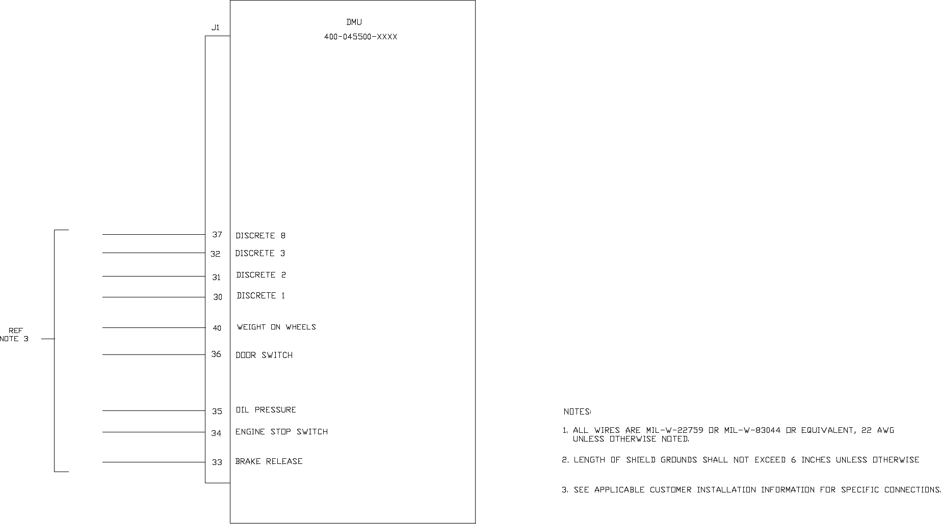
1.3.2.9.1 Brake Release
1.3.2.9.2 Oil Pressure
Data Type Logic Input
Logic State The OPEN condition is defined as a resistance to DC ground
from the AFIS DMU connector of 100,000 ohms or more, or a
DC level greater then 12 volts and not more than 36 volts.
The CLOSED condition is defined as a DC ground, zero ± 2 volts
with a maximum current of 2 ma.
Logic Format Atlantic Coast Airlines
An OPEN condition indicates the brakes are set.
A CLOSED condition indicates the brakes are released.
Mesaba Airlines
An OPEN condition indicates brakes are released.
A CLOSED condition indicates brakes are set.
Data Type Logic Input
Logic State The OPEN condition is defined as a resistance to DC ground
from the AFIS DMU connector of 100,000 ohms or more, or a DC
level greater then 12 volts and not more than 36 volts.
The CLOSED condition is defined as a DC ground, zero ± 2 volts
with a maximum current of 2 ma.
Logic Format An OPEN condition indicates there is oil pressure
A CLOSED condition indicates there is no oil pressure.

Global
AIRBORNE FLIGHT INFORMATION SYSTEM
IMAFISJWA 1-28
March/2001
1.3.2.9.3 Weight On Wheels
1.3.2.9.4 Engine Stop Switch
1.3.2.9.5 Door Switch
Data Type Logic Input
Logic State The OPEN condition is defined as a resistance to DC ground
from the AFIS DMU connector of 100,000 ohms or more, or a DC
level greater then 12 volts and not more than 36 volts.
The CLOSED condition is defined as a DC ground, zero ± 2 volts
with a maximum current of 2 ma.
Logic Format An OPEN condition indicates the aircraft is in the air.
A CLOSED condition indicates the aircraft is on the ground.
Data Type Logic Input
Logic State The OPEN condition is defined as a resistance to DC ground
from the AFIS DMU connector of 100,000 ohms or more, or a DC
level greater then 12 volts and not more than 36 volts.
The CLOSED condition is defined as a DC ground, zero ± 2 volts
with a maximum current of 2 ma.
Logic Format An OPEN condition indicates normal engine operation.
A CLOSED condition held for at least 2 seconds indicates the
engine is shut down.
Data Type Logic Input
Logic State The OPEN condition is defined as a resistance to DC ground
from the AFIS DMU connector of 100,000 ohms or more, or a DC
level greater than 12 volts and not more than 36 volts.
The CLOSED condition is defined as a DC ground, zero ± 2 volts
with a maximum current of 2 ma.
Logic Format An OPEN condition indicates the door is closed.
A CLOSED condition indicates the door is open.

Global
AIRBORNE FLIGHT INFORMATION SYSTEM
IMAFISJWA 1-29
March/2001
1.4 UNITS AND ACCESSORIES SUPPLIED
1.4.1 DATA MANAGEMENT UNIT
The Data Management Unit (DMU) is available in the following variations.
PN 400-045500-0003 which is the standard DMU and supports VHF and AERO-C (SATAFIS)
data communications.
PN 400-045500-0005 which supports aeronautical 741 satellite data communications (e.g.
Honeywell/Racal) as well as VHF data communications.
PN 400-045500-0130 which supports regional airline data entry, displays and VHF
Communications and AERO-C (SATAFIS) data communications.
PN 400-045500-0210 which supports WX Graphics capability on GNS-XLS and supports VHF
and AERO-C (SATAFIS) data communications.
PN 400-045500-2010 which supports WX Graphics capability on GNS-XLS and supports
AERO-H (741) satellite data communications (e.g. Honeywell/Racal) as well as VHF data
communications.
PN 400-045500-0211 which supports Dual GNS-XLS WX Graphics capability, as well as, NZ
2000 WX Graphics and supports VHF, AERO-C (SATAFIS) data communications.
PN 400-045500-2011 which supports Dual GNX-XLS WX Graphics capability, as well as, NZ
2000 WX Graphics and supports VHF, AERO-C (SATAFIS), AERO H/H+, AERO I
(ARINC741) satellite data communications. Supports Honeywell Aircraft Condition Monitoring
System (ACMS) which is a part of the Honeywell Flight Data Acquisition Management System
(FDAMS)
Other DMUs no longer manufactured:
PN 400-045500-0001 supports VHF data communication only.
PN 400-045500-0002 support VHF data communication only and has fuel flow information to
be used with a GNS 500 navigational system.
PN 400-045500-0004 supports VHF and aeronautical-’C’ data communications and has fuel
flow information to be used with a GNS-500 navigational system.
PN 400-045500-0006 supports aeronautical 741 satellite data communications, VHF data
communications and fuel flow information to be used with a GNS-500 navigational systems.
PN 42000-01-01 supports VHF data communication only and can only be used with GNS 500
and 1000 flight management systems.
PN 42000-02-02 supports VHF data communication only, has fuel flow information to be used
with a GNS 500 navigational system and can only be used with GNS 500 and 1000 flight
management systems.

Global
AIRBORNE FLIGHT INFORMATION SYSTEM
IMAFISJWA 1-30
March/2001
PN 42000-03-03 supports VHF and aeronautical ’C’ data communications. This DMU can only
be used with GNS flight management systems.
PN 42000-04-03 supports VHF, aeronautical ’C’ data communications and has fuel flow
information to be used with a GNS 500 navigational system. This DMU can only be used with
GNS flight management systems.
1.4.2 FLIGHT PLANNING SERVICE
Flight Planning Service includes planning and pre-departure clearance service. Services include
weather briefing, flight plan creation and filing, pre-departure delivery and arrival/departure
reservations.
Details on subscription fees and specifically what other capabilities are available can be obtained
by contacting the Global Data Center, telephone number 1-888-634-3330.
The following page (figure 1-1) contains a copy of the AFIS Graphics Service and Database
Application. After printing off a copy, complete all entries and fax to the number shown on the
form.

Global
AIRBORNE FLIGHT INFORMATION SYSTEM
IMAFISJWA 1-31
March/2001
Figure 1-1
Global
AIRBORNE FLIGHT INFORMATION SYSTEM
IMAFISJWA 1-32
March/2001
THIS PAGE IS RESERVED

Global
AIRBORNE FLIGHT INFORMATION SYSTEM
IMAFISJWA 1-33
March/2001
1.4.3 DMU CONFIGURATION MATRIX
Table 1-10
OPTIONS
DMU 42000-XXXX DMU 400-045500-XXXX
-01-01 -02-02 -03-03 -04-03 -0001 -0002 -0003 -0004 -0005 -0006 -0130 -0210 -2010 -0211 -2011
67 PIN CONNECTOR YES YES YES YES NO NO NO NO NO NO NO NO NO NO NO
106 PIN CONNECTOR NO NO NO NO YES YES YES YES YES YES YES YES YES YES YES
FUEL FLOW NO YES NO YES NO YES NO YES NO YES NO NO NO NO NO
COLOR CDU DISPLAY NO NO YES YES MOD4 MOD4 YES YES YES YES YES YES YES YES YES
10 LINE MONO CDU NO NO YES YES MOD4 MOD4 YES YES YES YES YES YES YES YES YES
GLOBAL SCU SAT SYSTEM NO NO YES YES NO NO YES YES YES NO YES YES YES YES YES
ARINC 429 FMS INTERFACE NO NO NO NO YES YES YES YES YES YES YES YES YES YES YES
TRIPLE PORT DTU PN 15655-X YES YES YES YES YES YES YES YES YES YES YES YES YES YES YES
DTU PN 43000-01-01-X YES YES YES YES YES YES YES YES YES YES YES YES YES YES YES
OTHER MFG. SAT SYSTEMS NO NO NO NO NO NO NO NO YES YES NO NO YES NO YES
ARINC 739 FMS INTERFACE NO NO NO NO NO NO NO NO NO NO NO NO NO YES YES
FDAMS INTERFACE NO NO NO NO NO NO NO NO NO NO NO NO NO NO YES

Global
AIRBORNE FLIGHT INFORMATION SYSTEM
IMAFISJWA 1-35
March/2001
1.5 ACCESSORIES REQUIRED
1.5.1 DMU INSTALLATION KIT
The DMU Installation Kit PN 149-017305-6850 is required to install DMU PN 400-045500-XXXX.
The DMU Installation Kit PN 149-017301-5970 is required to install DMU PN 42000-XX-XX.
1.5.2 CONFIGURATION MODULE UNIT
The Configuration Module Unit is to be mounted on the rear of the 1/2 ATR Short Tray.
1.5.3 VHF ANTENNA
If the VHF antenna is to be shared with another VHF radio then the optional Antenna Switching
Unit (ASU) is required.
1.6 OPTIONAL ACCESSORIES
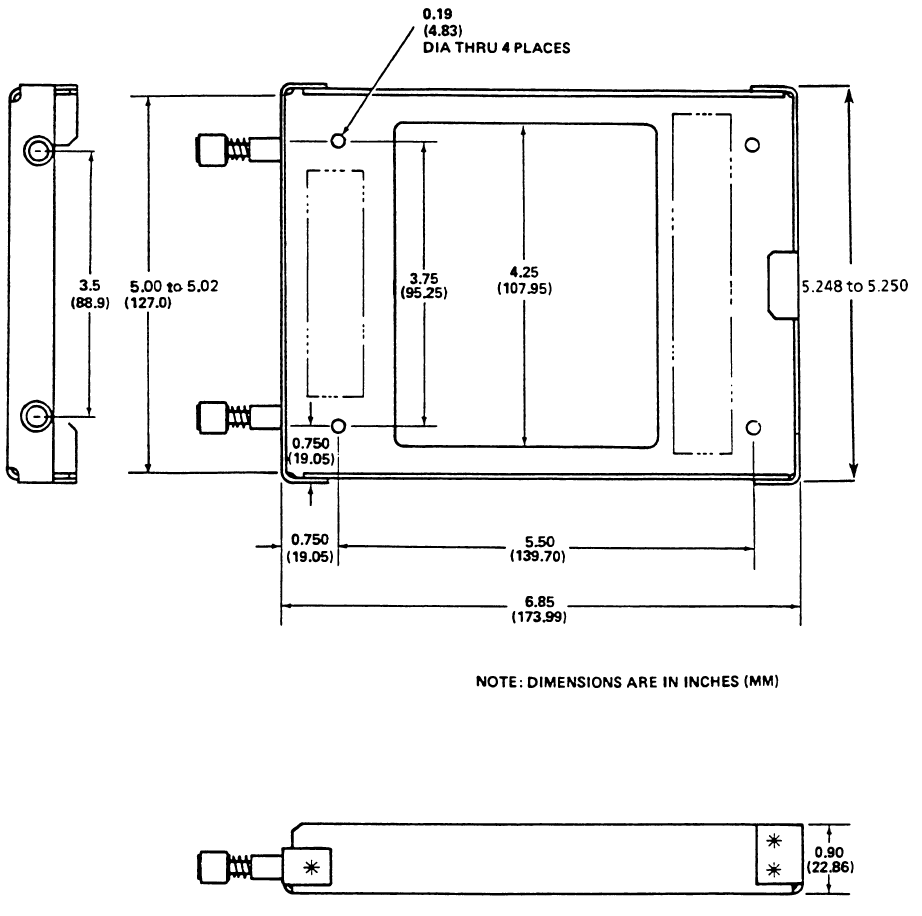
1.6.1 DATA TRANSFER UNIT
The Data Transfer Unit (DTU) is required if flight plan or weather information is to be loaded into
the DMU via a disk from the AFISCOM system. The DTU is available in the following variations:
Triple Port DTU which is used to provide data base information to GWS flight management
systems and data information to DMU:
1/2 ATR Short Tray PN 42701-1 Qty 1 ea
DMU Connector PN 129-214251-01 Qty 1 ea
1/2 ATR Short Tray PN 42701-1 Qty 1 ea
DMU Connector PN 42770-1 Qty 1 ea
Configuration module PN 31990-1 Qty 1 ea
Triple Port DTU PN 15655-0101 (Gray)
Triple Port DTU PN 15655-0201 (Black)

Global
AIRBORNE FLIGHT INFORMATION SYSTEM
IMAFISJWA 1-36
March/2001
Single Port DTU (no longer manufactured) supplies data information to DMU:
1.6.1.1 DTU INSTALLATION KIT
The DTU installation kit is required if DTU is installed. Select one of the following options:
DTU Installation Kit, Grey, for DTU PN 43000-01-01-X
PN 149-017302-5983 (kit no longer available from Honeywell)
DTU Installation Kit, Black, for DTU PN 43000-01-01-X
PN 149-017302-5984 (kit no longer available from Honeywell)
Triple Port DTU Installation Kit PN 129-215678-01
1.6.2 ANTENNA SWITCHING UNIT
The ANTENNA SWITCHING UNIT (ASU) is required if a VHF antenna is going to be shared
between the DMU and another VHF communication radio.
If an ASU is being installed, the Antenna Switching Unit Installation Kit is required:
PN 43000-01-01-1 Gray +8 VDC / +12 VDC
PN 43000-01-01-2 Black +8 VDC / +12 VDC
PN 43000-01-01-3 Gray +28 VDC
PN 43000-01-01-4 Black +28 VDC
PN 43000-01-01-5 Gray +8 VDC / +12 VDC
PN 43000-01-01-6 Black +8 VDC / +12 VDC
PN 43000-01-01-7 Gray +28 VDC
PN 43000-01-01-8 Black +28 VDC
DTU Connector PN 12893-1 Qty 1 ea
Grey with Tray PN 43010-1 Qty 1 ea
DTU Connector PN 12893-1 Qty 1 ea
Black with Tray PN 43010-2 Qty 1 ea
DTU Connector PN 129-215678-01 Qty 1 ea
Antenna Switching Unit PN 44000-1

Global
AIRBORNE FLIGHT INFORMATION SYSTEM
IMAFISJWA 1-37
March/2001
ASU Installation Kit PN 149-017303-5990
1.6.3 SATELLITE SYSTEM (SATAFIS)
If the aeronautical “C” satellite system, SATAFIS, is to be installed the following equipment
is required:
SCU Installation Kit - PN 149-017536-0001
1.6.4 PRINTER
Details on specifically what printer will operate with the DMU and other requirements can be
obtained by contacting the Global Data Center.
1.6.5 CABIN PERSONAL COMPUTER
Details on specifically what Personal Computer is supported with the DMU and other requirements
can be obtained by contacting the Global Data Center.
1.7 LICENSE REQUIREMENTS
1.7.1 VHF RADIO
Aircraft must have proper VHF radio license to operate on frequencies between 128.000 Mhz to
132.000 Mhz for DMU.
1.7.2 INMARSAT SATELLITE APPROVAL
Aircraft must be registered with INMARSAT for use of the SATAFIS system if installed.
INMARSAT approval is coordinated through the Honeywell Global Data Center.
ASU Connector PN 12893-2 Qty 1 ea
EQUIPMENT PART NUMBER
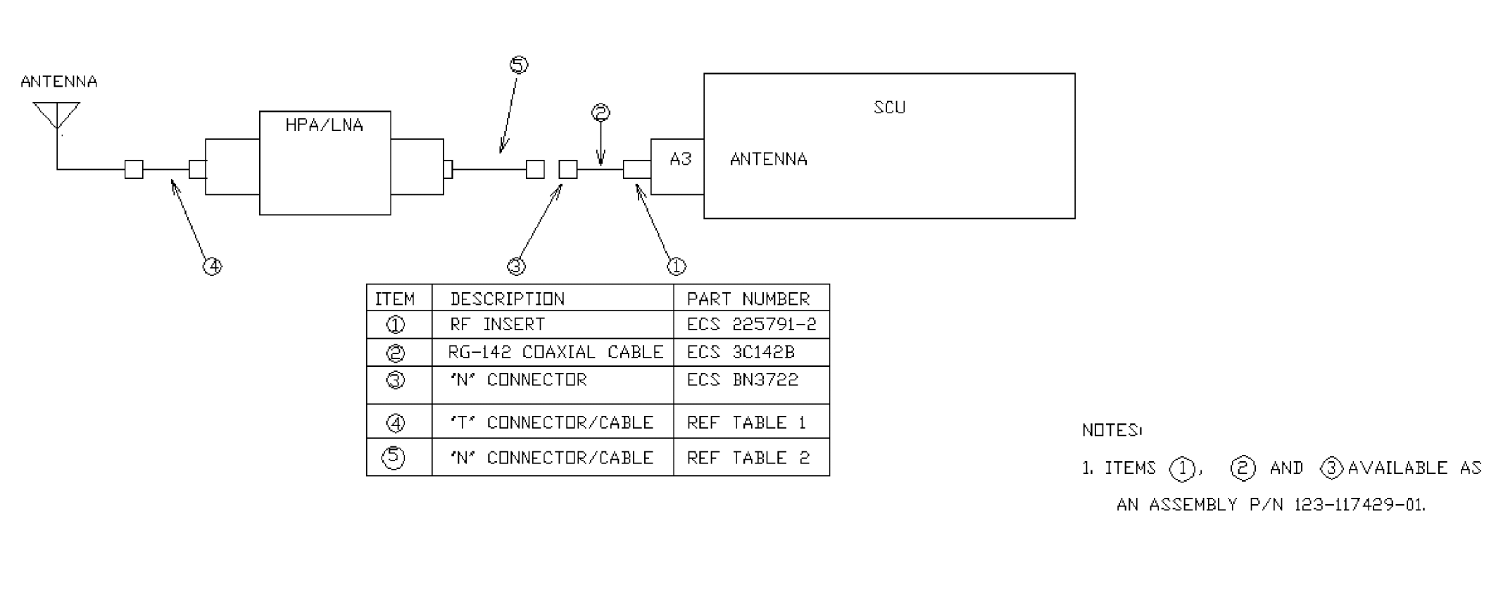
Satellite Communication Unit (SCU) 153-017311-01
High Power Amplifier/Low Noise Amplifier (HPA/LNA) 153-017310-01
Low Profile Jet Blade Antenna 121-017537-01
Jet Blade Antenna (no longer manufactured) 121-017308-01
Mounting Tray PN 300-317337-01 Qty 1 ea
SCU Connector PN 129-217338-01 Qty 1 ea
Coaxial Cable Adapter PN 123-117429-01 Qty 1 ea

Global
AIRBORNE FLIGHT INFORMATION SYSTEM
IMAFISJWA 1-38
March/2001
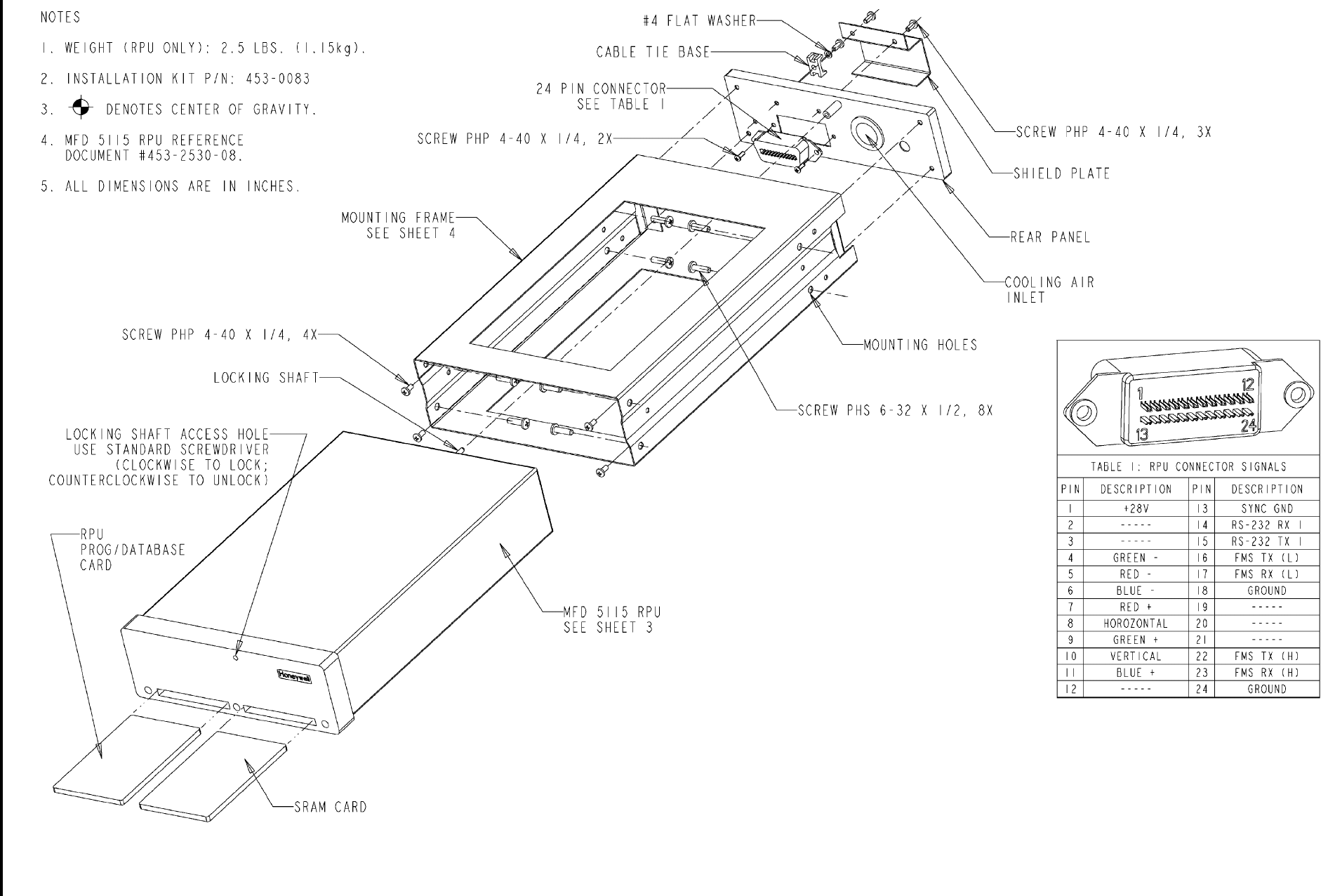
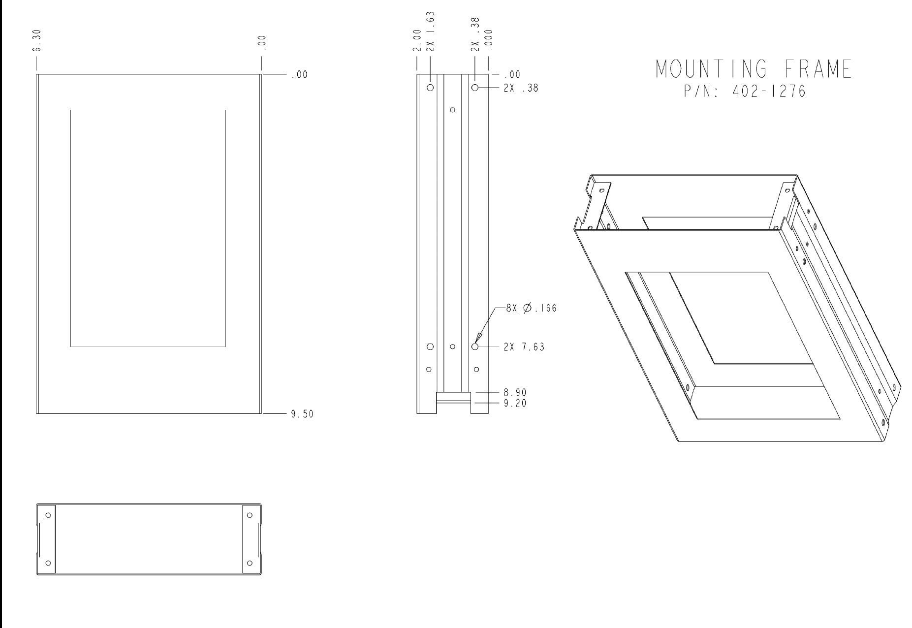
1.7.3 ARNAV RPU INSTALLATION KIT
The ARNAV RPU installation kit, PN 453-0083, is required to install the ARNAV MFD 5115 RPU,
PN 453-2503-08. Assemble tray per sheet 1 of Figure 2-16.
1.8 INSTRUCTIONS FOR CONTINUED AIRWORTHINESS
The instructions for continued airworthiness given in the TC or STC approvals for this product
supplements or supersedes the instructions for continued airworthiness in this manual. Most
Honeywell products are designed and manufactured to allow "on condition maintenance." On
condition maintenance is described as follows; There are no periodic service requirements
necessary to maintain continued airworthiness. No maintenance is required until the equipment
does not properly perform it’s intended function. When service is required, a complete
performance test should be accomplished following any repair action. Consult the appropriate unit
Maintenance/Overhaul Manual for complete performance test information.
DESCRIPTION ARNAV PART NUMBER QTY
RPU Rear Panel Assembly 452-0116 1
Shield Plate 402-1277 1
RPU Frame (marked with kit assy, PN 453-0083 402-1276 1
Washer, Flat #4 x 1/4 SS 246-0004 1
Screw, PHP 4-40 x 1/4 SS 201-0404 7
Screw, PHP 3-48 x 3/8 STL 201-0306 2
Base, Cable Tie 182-1032 1
Receptacle, Panel 24 pin 150-1151 1
Screw, 6-32 x 1/2 PH Slot SS 207-0602 8
Global
AIRBORNE FLIGHT INFORMATION SYSTEM
IMAFISJWA 2-1
March/2001
SECTION 2
INSTALLATION
2.0 INTRODUCTION
The component sizes, centers of gravity, tray dimensions and installation locations are shown in
Figures 2-1 through 2-15.
NOTE:
The conditions and tests required for TSO approval of this article are minimum
performance standards. It is the responsibility of those desiring to install this
article either on or within a specific type or class of aircraft to determine that the
aircraft installation conditions are within TSO standards. The article may be
installed only if further evaluation by the applicant documents an acceptable
installation and is approved by the Administrator.
2.1 UNPACKING AND INSPECTING EQUIPMENT
Exercise extreme caution when unpacking equipment. Perform a visual inspection of the unit for
evidence of physical damage incurred during shipment. If a damage claim must be filed, save the
shipping container and all packing materials to substantiate your claim. The claim should be filed
as soon as possible. The shipping container and packing materials should be retained in the
event that storage or re-shipment of the equipment is necessary.
2.2 GENERAL INSTALLATION REQUIREMENTS
(a) For GNS-1000 Installations: The maximum recommended cable length between the
DMU and Flight Management Computer (FMC) is 50 feet. Do not bundle DMU/FMC
data lines or antenna cables with any power cables.
(b) For GNS-500A Installations: The maximum recommended cable length between the
DMU and Control Display Unit (CDU) is 50 feet. Do not bundle DMU/CDU data lines or
antenna cables with any power cables.
(c) For GNS-X, GNS-XLS, GNS-XL, GNS-XES flight management systems Installations:
The maximum cable length between the DMU and the flight management systems is 50
feet. Do not bundle DMU/flight management systems data lines or antenna cables with
any power cables.
(d) The maximum recommended cable length between the DMU and DTU is 50 feet. Do
not bundle DMU/DTU data lines or antenna cables with any power cables.
(e) The maximum recommended cable length between the DMU and SCU is 100 feet. Do
not bundle DMU/SCU data lines or antenna cables with any power cables.
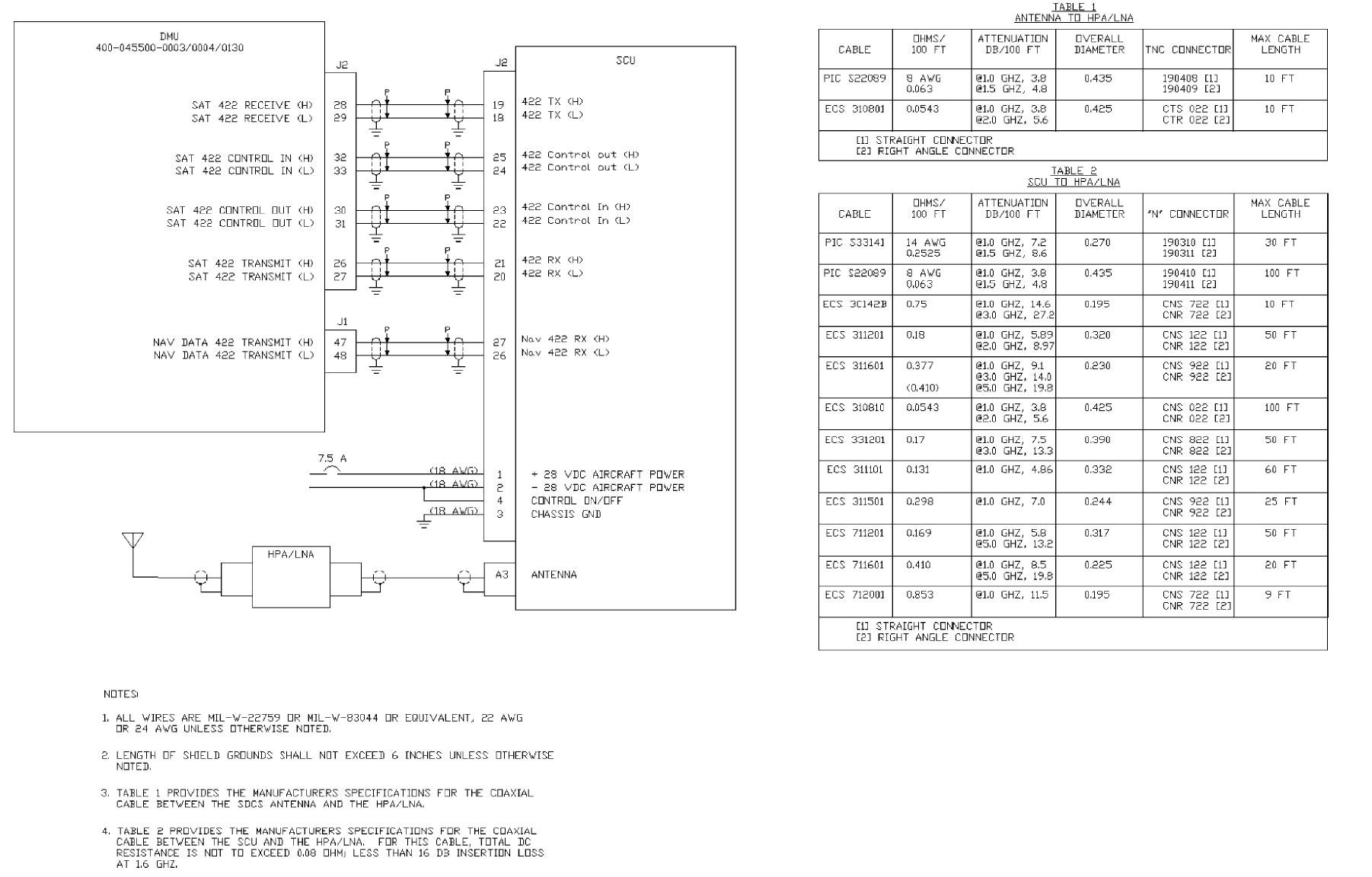
(f) The maximum cable length between the Jet Blade antenna and HPA/LNA is 10 feet,
refer to Figure 3-31, Table 1. The maximum cable length between Low Profile Jet Blade
antenna and HPA/LNA is 10 feet, refer to Figure 3-31, Table 1.
(g) The maximum cable length between the SCU and HPA/LNA is determined by the type
of cable used. Refer to Table 2 in Figure 3-31 for cable length information.
Global
AIRBORNE FLIGHT INFORMATION SYSTEM
IMAFISJWA 2-2
March/2001
(h) The DMU has heat removed by conduction: make sure the unit is installed in a location
where the ambient temperatures are -67° F to +131° F (-55° C to +55° C).
(i) The DTU should be mounted within the pressure vessel in a temperature controlled
environment of +5° F to +131° F (-15° C to +55° C).
(j) Mount SCU tray to provide good electrical bonding to airframe ground. Lightning strike
protection, RF susceptibility and emission characteristics are dependent on good
electrical grounding of the tray and cable shield returns.
(k) The SCU should be mounted within the pressure vessel in a temperature controlled
environment of -13° F to +131° F (-25° C to +55° C).
2.3 DATA MANAGEMENT UNIT (DMU) INSTALLATION
(a) See Figures 2-1 and 2-2.
(b) Mount DMU 1/2 ATR short tray.
(c) Install DMU in tray.
2.4 DATA TRANSFER UNIT (DTU)
(a) See Figures 2-5 through 2-10.
(b) Mount DTU in aircraft cockpit in a location easily accessible to pilot.
(c) Two mounting provisions are available; DZUS or tray mounting.
NOTE:
The DTU uses AUL-SPEC Dzus fasteners as standard mounting provisions.
However, for aircraft not equipped with these fastener strips see Figure 2-9.
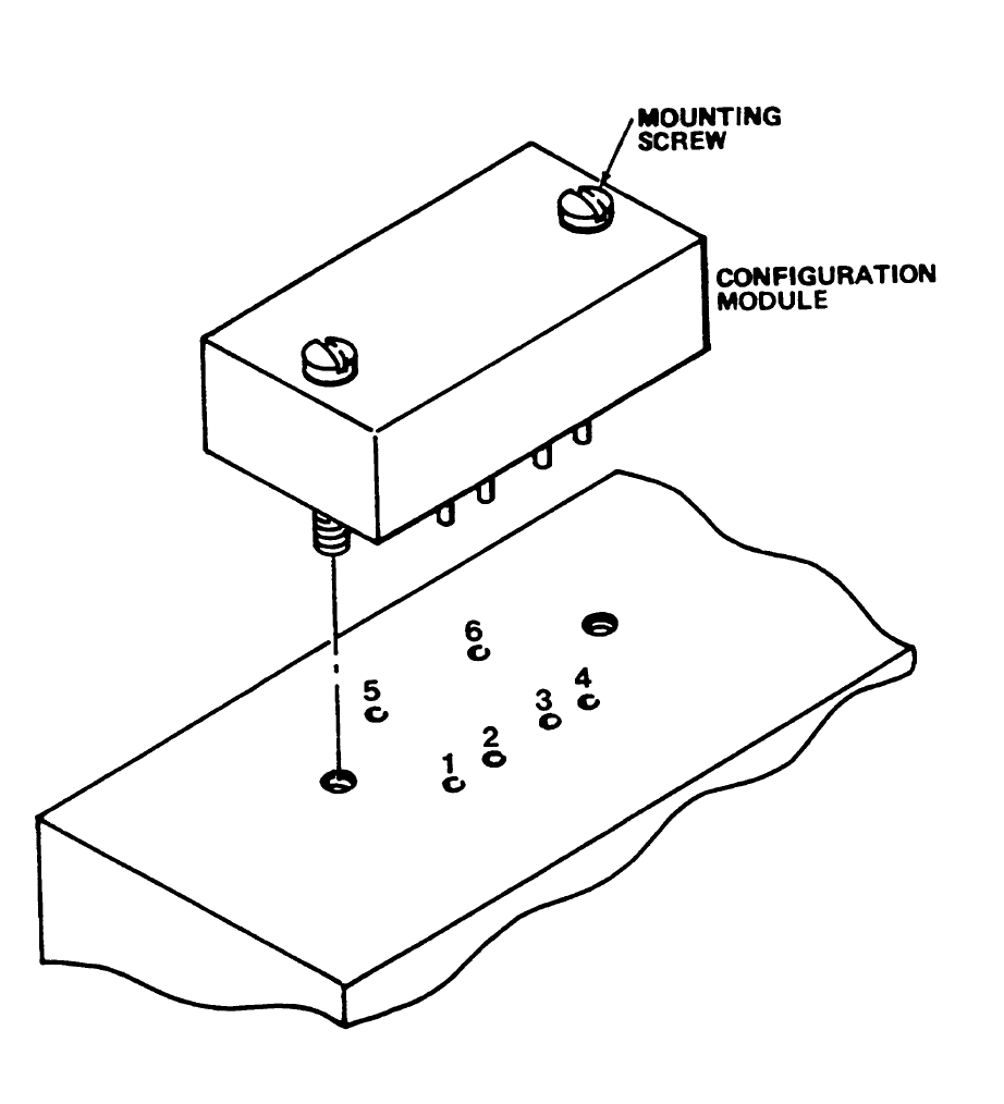
2.5 CONFIGURATION MODULE IN DATA MANAGEMENT UNIT (DMU) TRAY
(a) For ease of assembly it is recommended that the DMU be wired to the configuration
module per Section 3, ELECTRICAL INSTALLATION prior to installing configuration
module. The wires are to be soldered to the tray pins.
NOTE:
The location and number of the configuration module pins are stamped on
the tray for reference during wiring.
(b) Remove configuration module from packing, be sure not to bend pins of module.
(c) Place module on tray as shown in Figures 2-2 and 2-3 aligning pins with holes in tray.
Tighten screws once module is fitted properly. Do not force seating of module.
Global
AIRBORNE FLIGHT INFORMATION SYSTEM
IMAFISJWA 2-3
March/2001
2.6 SATELLITE COMMUNICATION UNIT (SCU)
(a) See Figures 2-12 and 2-13.
(b) Mount 1/4 ATR short rack per Paragraph 2.2.
(c) Install SCU in rack and secure hold down mechanism.
2.7 HIGH POWER AMPLIFIER/LOW NOISE AMPLIFIER INSTALLATION (HPA/LNA)
(a) See Figure 2-14.
(b) The HPA/LNA should be mounted in an area that ensures optimum antenna placement.
Coax lengths should be within maximum length limits per Figure 3-31 Table 2.
(c) The HPA/LNA should be well bonded to the aircraft skin per Paragraph 2.8.1.
2.8 ANTENNA INSTALLATION
2.8.1 Bonding Checklist
(a) The recommended bonding jumper for DC and low frequency AC (50 kHz) is braided
wire. For radio frequencies greater than 50 khz use a flat metal strap with a length to
width ratio of 1. For brass and copper alloys the strap should be 0.025 inch thick. For
aluminum alloys the strap should be 0.040 inch thick.
(b) Periodic inspections should be made of aircraft bonding devices since they are
subject to wear and breakage.
(c) After major modification, painting, or repairs, inspect control surfaces, inspection
plates, and drain masts to assure that proper metal-to-metal contact is maintained.
2.8.2 Low Profile Jet Blade Antenna Installation (See Figure 2-15)
(a) The Jet Blade antenna should be mounted on the center line of the aircraft on the
aircraft skin which is horizontal during enroute flight.
(b) The antenna should be mounted on the top of the aircraft, over the cockpit or on top of
the tail of the aircraft.
NOTE:
This location reduces the possibility of obstructing satellite signals because of
shadowing.
(c) The antenna should be mounted as far as possible from other radiating devices (3 feet
minimum VHF comms, HF comms, etc.).
(d) The antenna should be well bonded to the aircraft skin per Paragraph 2.8.1 (a).
(e) The antenna should be sealed to the aircraft to prevent corrosion from forming
between the skin of the aircraft and the antenna.

Global
AIRBORNE FLIGHT INFORMATION SYSTEM
IMAFISJWA 2-4
March/2001
2.9 ARNAV RPU INSTALLATION
2.9.1 Installation Kit
An ARNAV MFD 5115 Installation Kit P/N 453-0083 is required to install the ARNAV MFD
5115 RPU.
2.9.2 Installation Guide
See figures 2-16 and 2-17.
2.9.3 Cooling Considerations
It is highly recommended to use forced air cooling. A duct port is provided on the install
tray. Make sure that the unit is installed in a location where the ambient temperature is
between -20° C and +70° C.
2.9.4 Installation Considerations
Wiring length between the RPU and the GNS-XLS CDU should be no more than 15 feet.
Wiring between the RPU and the DMU is unlimited.
Must be mounted inside the pressure vessel.
Should have access to front, to facilitate changing of the database PCMCIA card.
2.9.5 Database Card
To begin database service and receive the database card, please complete the form in
figure 1-1 and fax it to (602) 436-1501.
Global
AIRBORNE FLIGHT INFORMATION SYSTEM
IMAFISJWA 2-5
March/2001
DATA MANAGEMENT UNIT (DMU) PN 42000-XX-XX OR PN 400-045500-XXXX
Figure 2-1
Global
AIRBORNE FLIGHT INFORMATION SYSTEM
IMAFISJWA 2-6
March/2001
DMU TRAY PN 42701-1
Figure 2-2
Note: All dimensions are in inches (centimeters).
Global
AIRBORNE FLIGHT INFORMATION SYSTEM
IMAFISJWA 2-7
March/2001
Configuration Module Mounting Provision P/N 31990-1
Figure 2-3
NOTE:
1. Weight 0.102 lbs. (0.045 Kg) max.
DMU RACK
Global
AIRBORNE FLIGHT INFORMATION SYSTEM
IMAFISJWA 2-8
March/2001
Configuration Module Outline and Mounting P/N 31990-1
Figure 2-4
Global
AIRBORNE FLIGHT INFORMATION SYSTEM
IMAFISJWA 2-9
March/2001
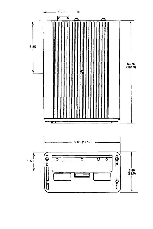
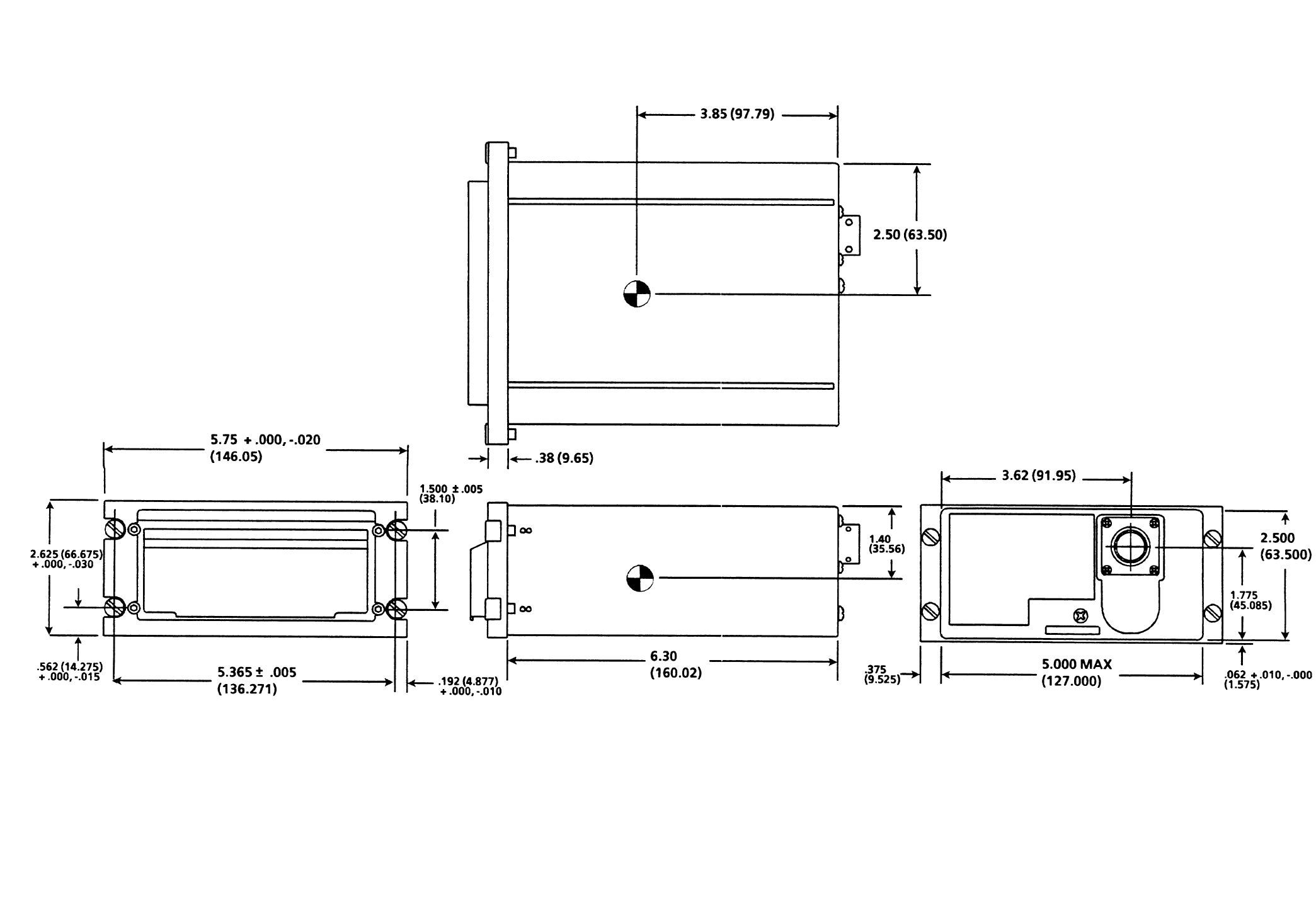
DATA TRANSFER UNIT (DTU) PN 43000-01-01-X
Figure 2-5
NOTE:
All dimensions are in inches (millimeters).
Global
AIRBORNE FLIGHT INFORMATION SYSTEM
IMAFISJWA 2-10
March/2001
THIS PAGE IS RESERVED
Global
AIRBORNE FLIGHT INFORMATION SYSTEM
IMAFISJWA 2-11
March/2001
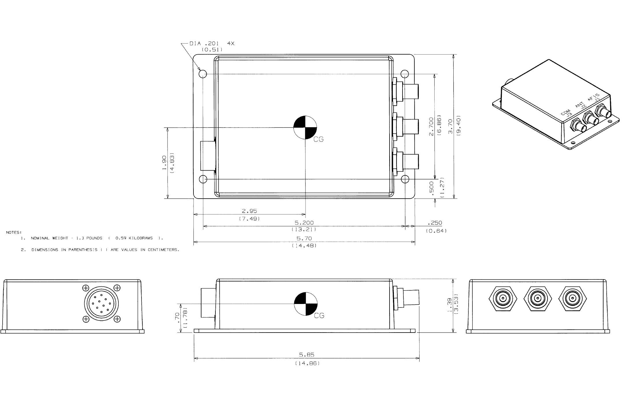
Triple Port DTU PN 15655-XXXX
Figure 2-6
NOTES:
1. All dimensions are in inches (millimeters).
Global
AIRBORNE FLIGHT INFORMATION SYSTEM
IMAFISJWA 2-13
March/2000
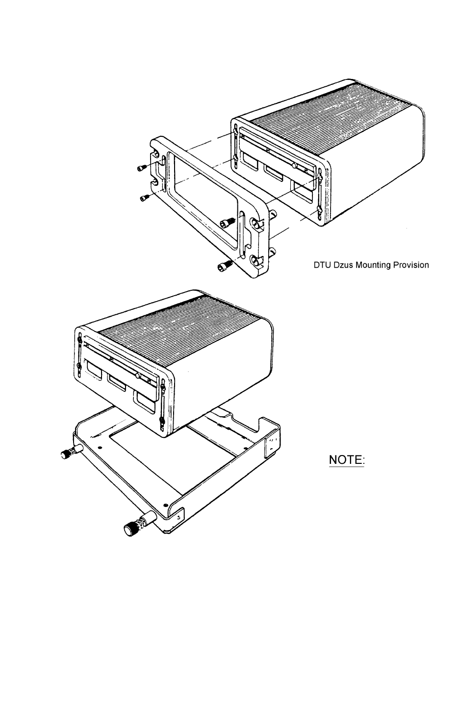
DTU TRAY MOUNTING
Figure 2-8
Figure 2-7
Figures 2-7 and 2-8 are
provided for DTU mounting
reference only.
Global
AIRBORNE FLIGHT INFORMATION SYSTEM
IMAFISJWA 2-14
March/2000
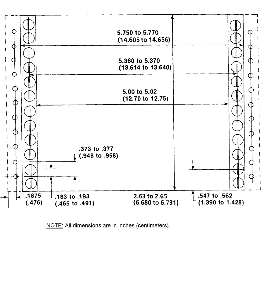
DTU INSTRUMENT PANEL MOUNTING PROVISION
Figure 2-9
Global
AIRBORNE FLIGHT INFORMATION SYSTEM
IMAFISJWA 2-15
March/2000
DTU TRAY PN 43010-X
Figure 2-10
Global
AIRBORNE FLIGHT INFORMATION SYSTEM
IMAFISJWA 2-16
March/2000
THIS PAGE IS RESERVED
Global
AIRBORNE FLIGHT INFORMATION SYSTEM
IMAFISJWA 2-17
March/2000
ANTENNA SWITCHING UNIT (ASU) PN 44000-1
DWG. NO. 155-06047-0000
Figure 2-11
Globall
AIRBORNE FLIGHT INFORMATION SYSTEM
IMAFISJWA 2-19
March/2000
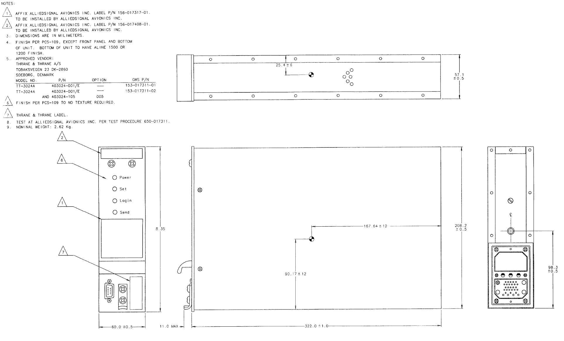
SATELLITE COMMUNICATION UNIT (SCU)
DWG. NO. 153-017311-01 REV AA
Figure 2-12
Global
AIRBORNE FLIGHT INFORMATION SYSTEM
IMAFISJWA 2-21
March/2001
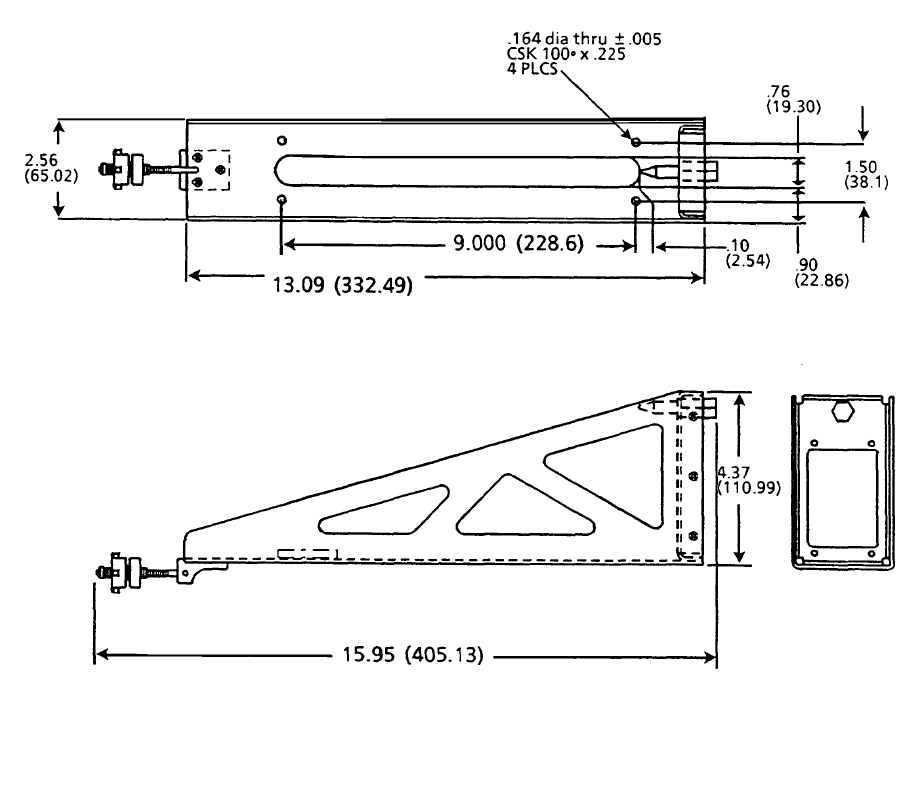
SCU TRAY PN 300-317337-01
Figure 2-13
NOTE: All dimensions are in inches (millimeters).
Global
AIRBORNE FLIGHT INFORMATION SYSTEM
IMAFISJWA 2-22
March/2001
THIS PAGE IS RESERVED
Global
AIRBORNE FLIGHT INFORMATION SYSTEM
IMAFISJWA 2-23
March/2001
HIGH POWER AMPLIFIER/LOW NOISE AMPLIFIER (HPA/LNA)
DWG. NO. 153-017310-01 REV AA
Figure 2-14
Global
AIRBORNE FLIGHT INFORMATION SYSTEM
IMAFISJWA 2-25
March/2001
LOW PROFILE JET BLADE ANTENNA
DWG. NO. 153-017537-01 REV AA
Figure 2-15
Global
AIRBORNE FLIGHT INFORMATION SYSTEM
IMAFISJWA 2-27
March/2001
MFD 5115 RPU
DWG. NO. 155-05453-0000, REV A, Sheet 1 of 4
Figure 2-16
Global
AIRBORNE FLIGHT INFORMATION SYSTEM
IMAFISJWA 2-29
March/2001
MFD 5115 RPU
DWG. NO. 155-05453-0000, REV A, Sheet 2 of 4
Figure 2-16
Global
AIRBORNE FLIGHT INFORMATION SYSTEM
IMAFISJWA 2-31
March/2001
MFD 5115 RPU
DWG. NO. 155-05453-0000, REV A, Sheet 3 of 4
Figure 2-16
Global
AIRBORNE FLIGHT INFORMATION SYSTEM
IMAFISJWA 2-33
March/2001
MFD 5115 RPU
DWG. NO. 155-05453-0000, REV A, Sheet 4 of 4
Figure 2-16
Global
AIRBORNE FLIGHT INFORMATION SYSTEM
IMAFISJWA 3-1
March/2001
SECTION 3
ELECTRICAL INSTALLATION
3.0 GENERAL
The basic system interconnect wiring is shown in Figure 3-1 through Figure 3-31 and the
connectors for each system component are shown in Figures 3-32 through 3-43.
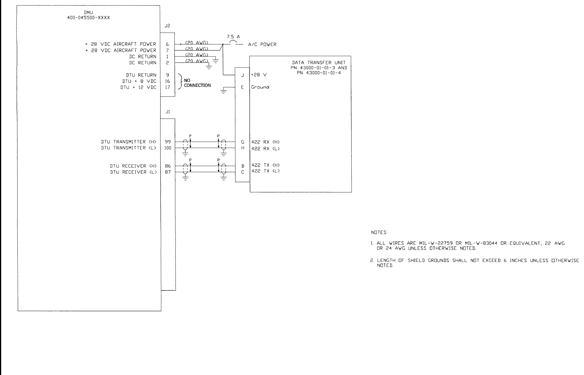
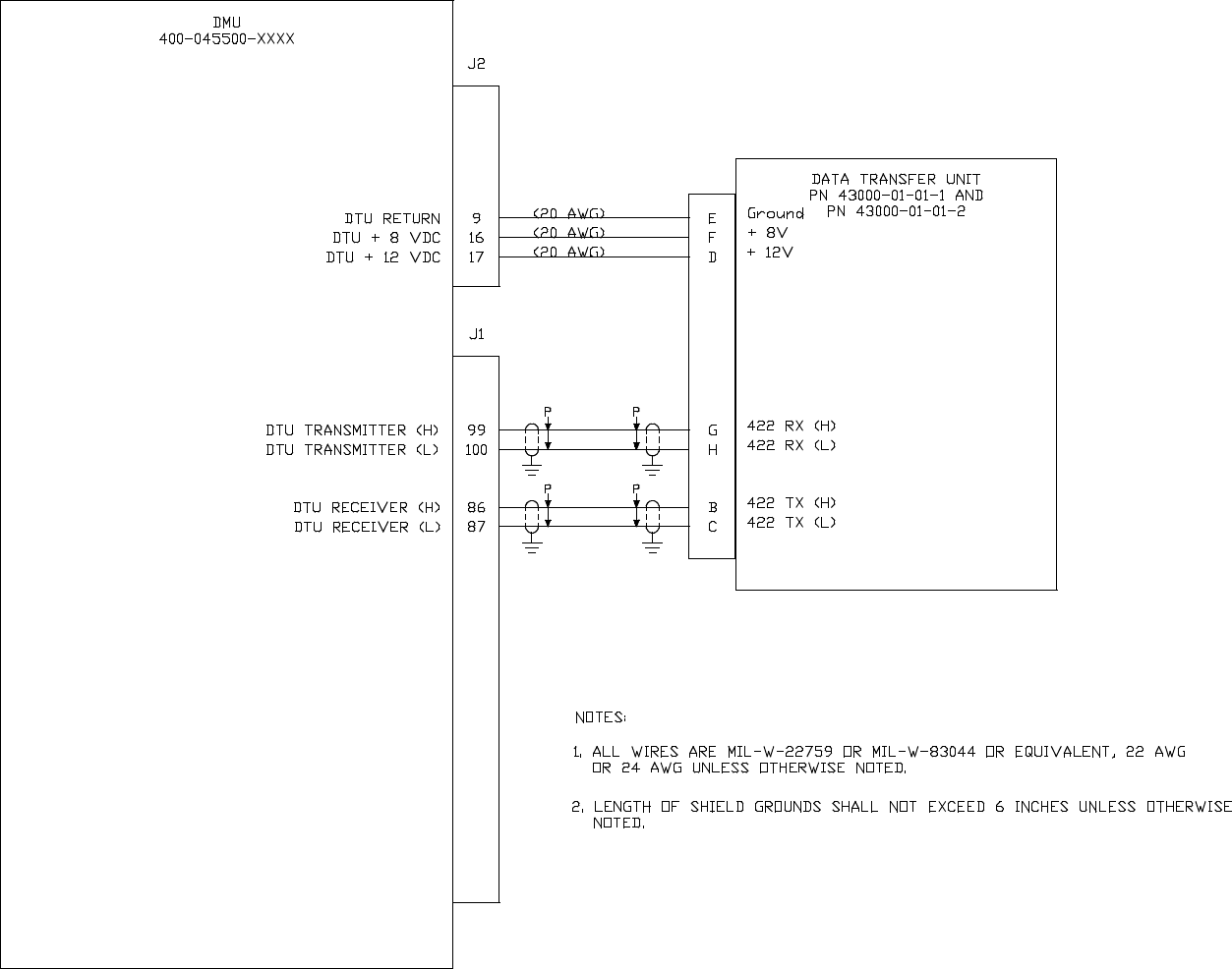
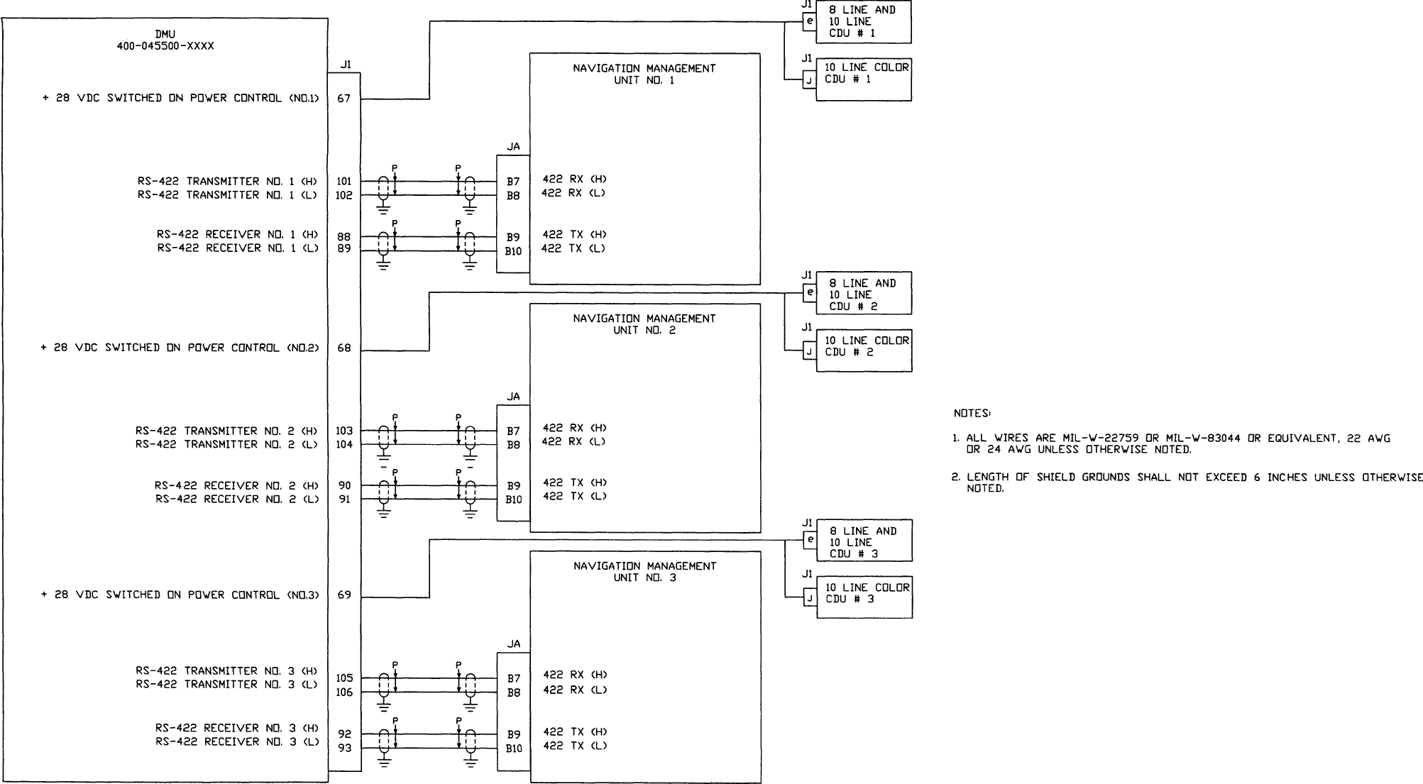
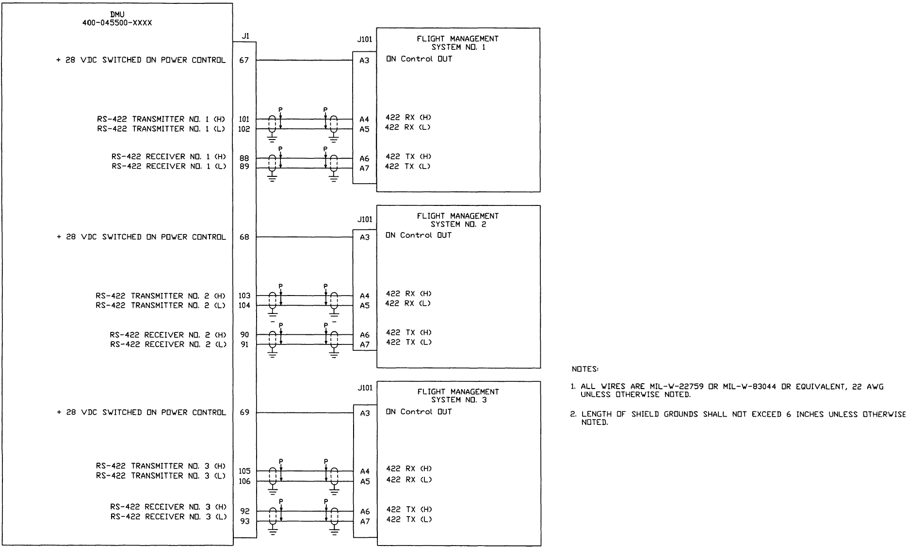
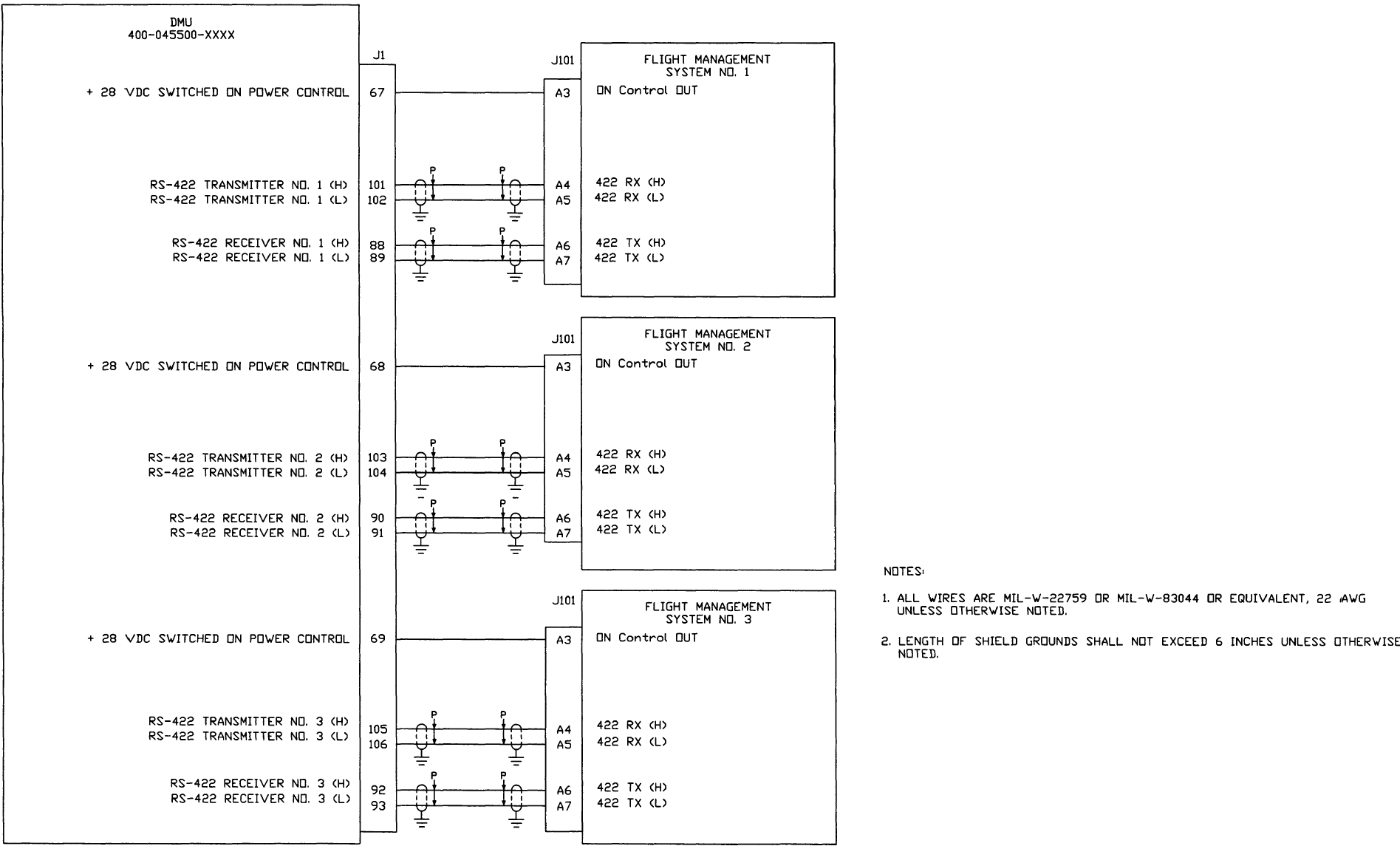
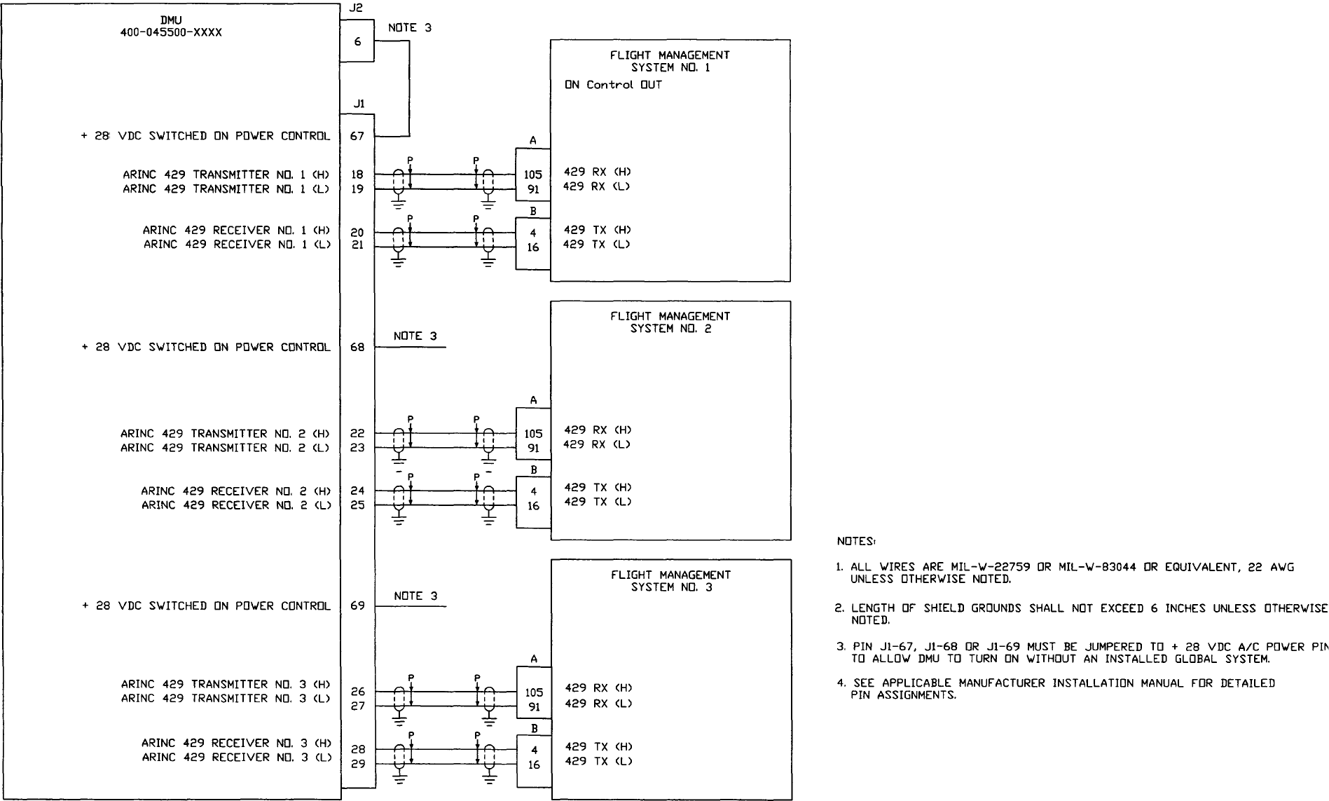
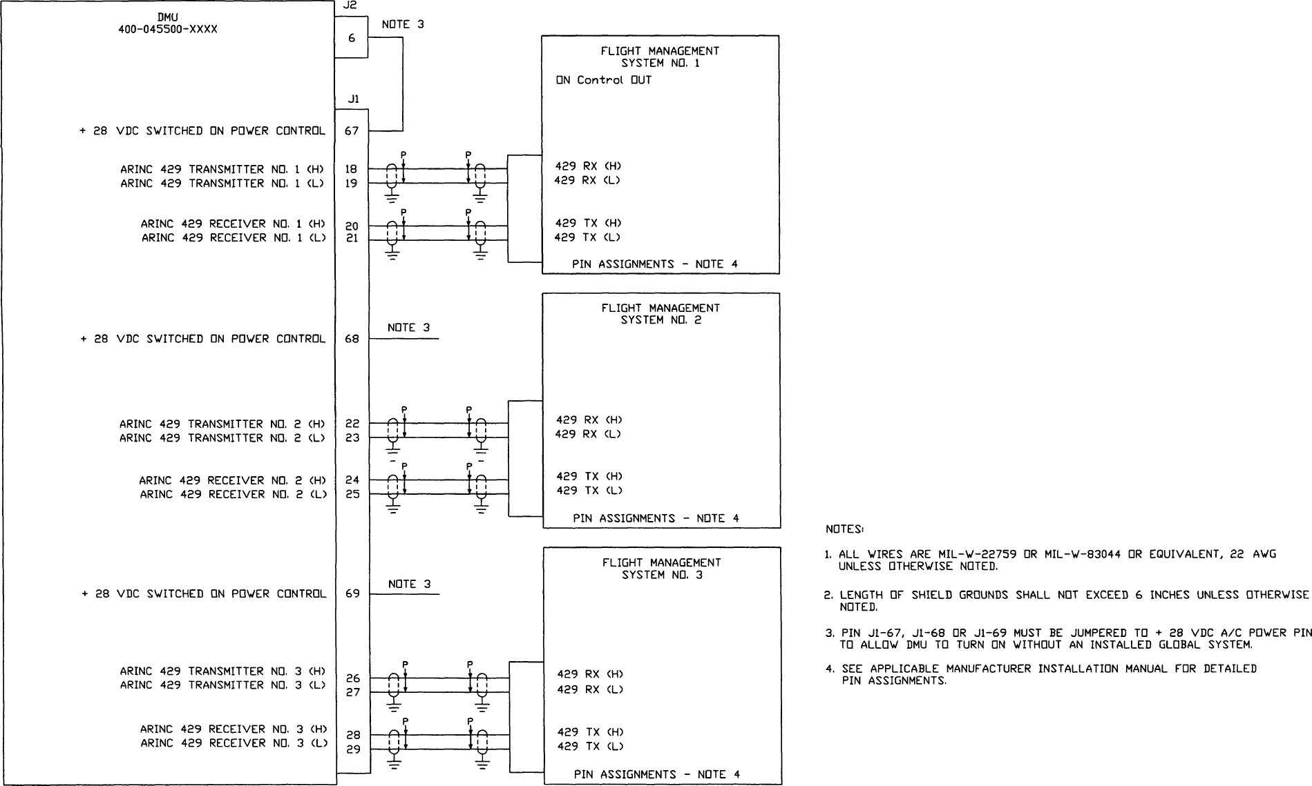
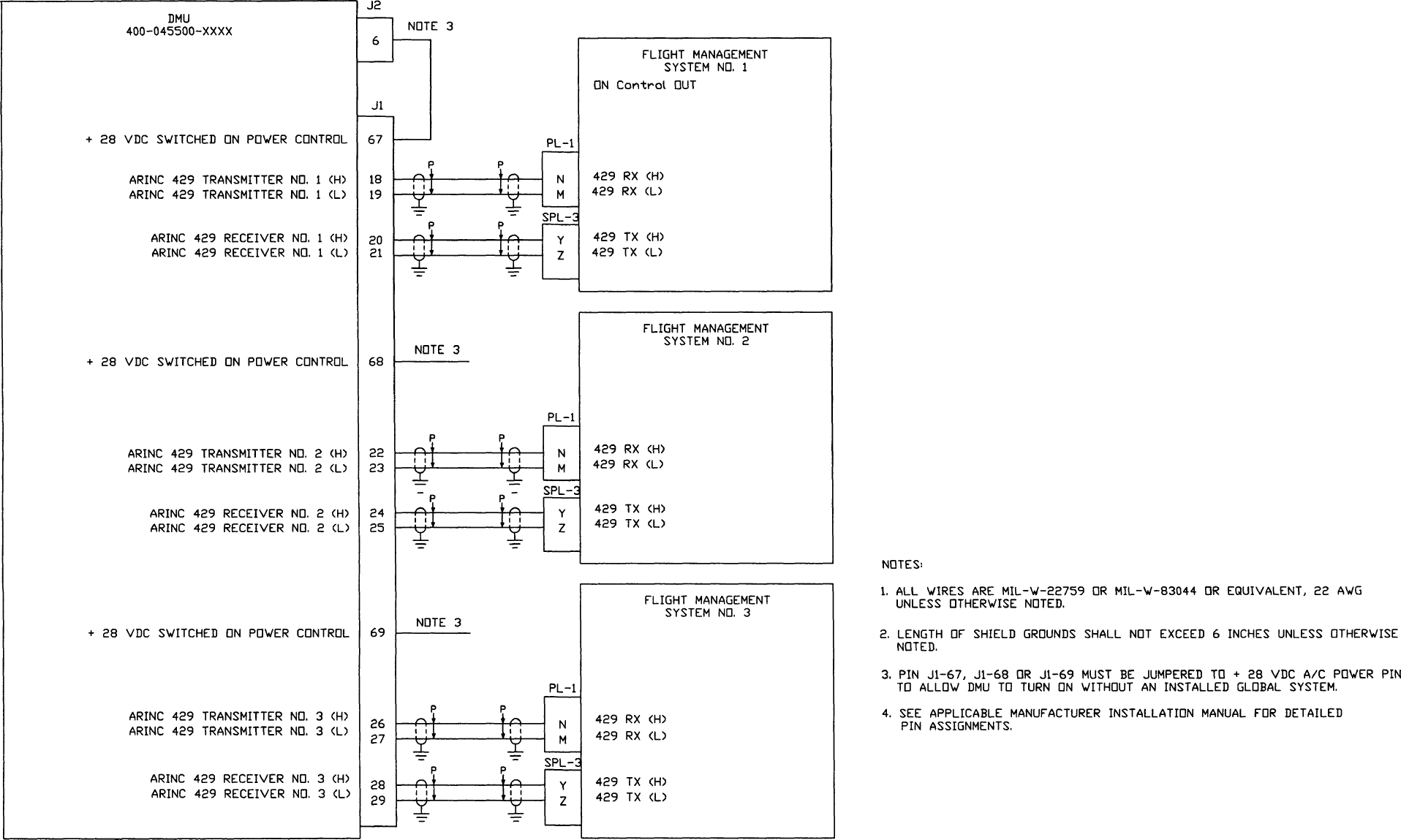
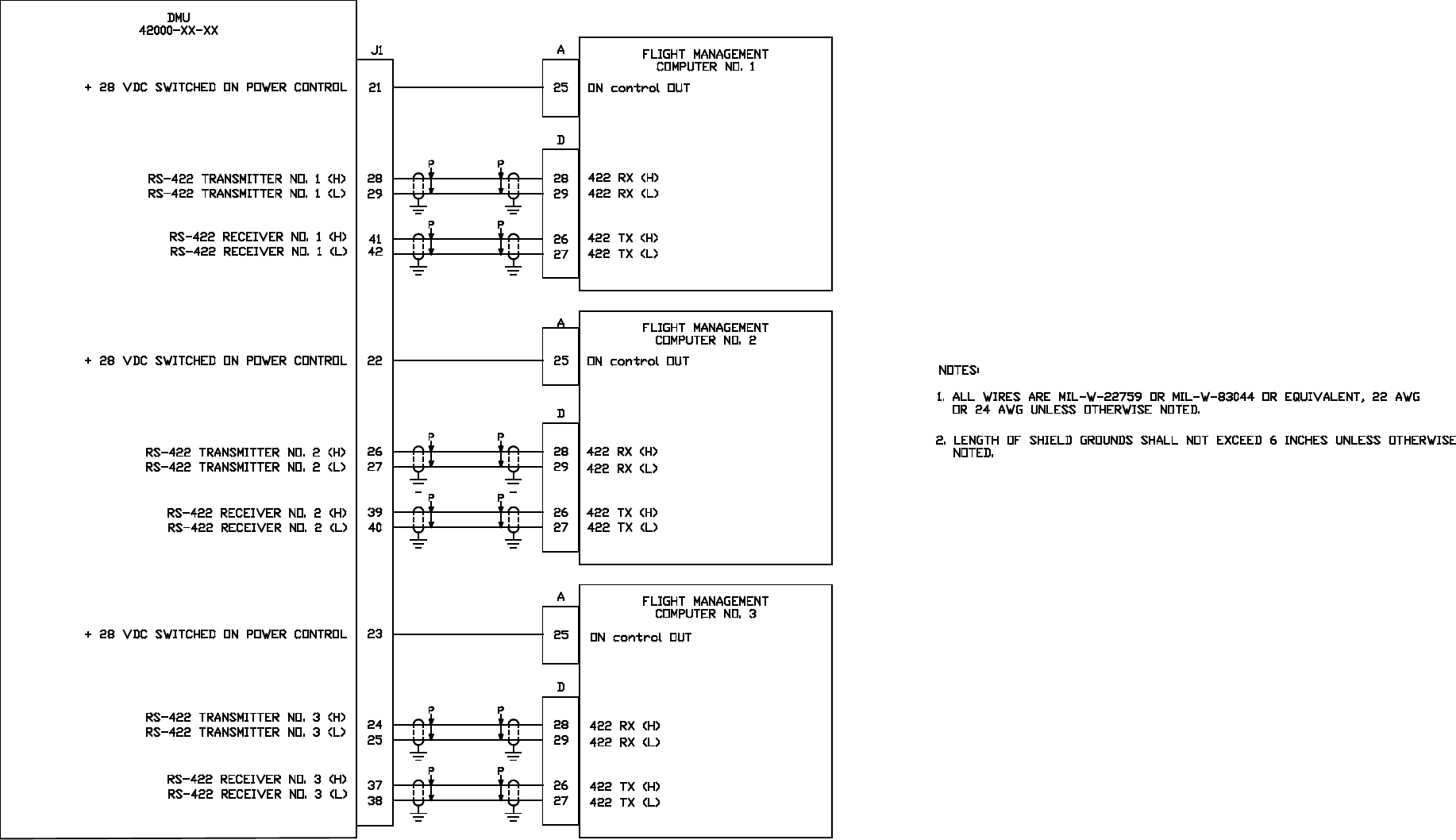
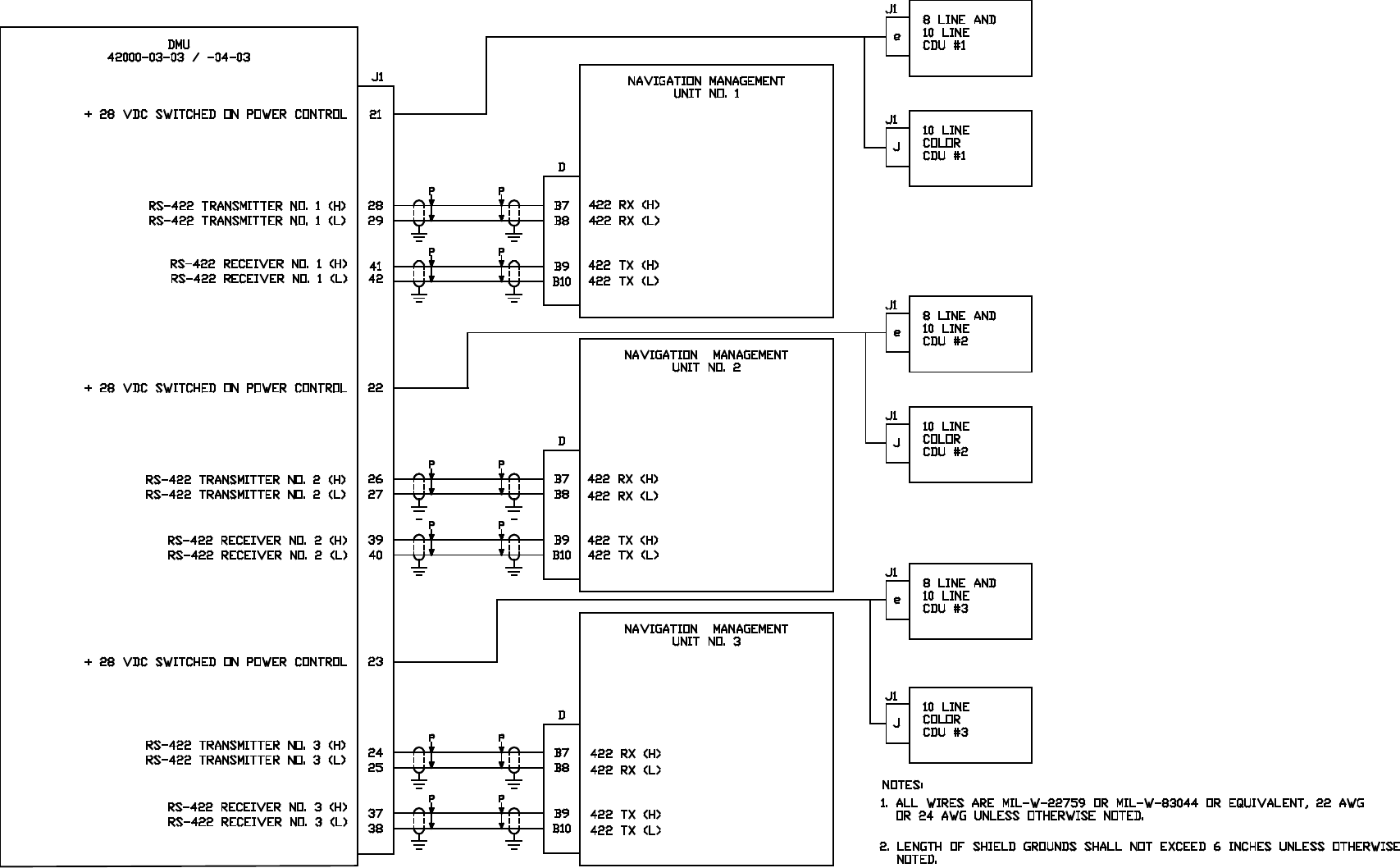
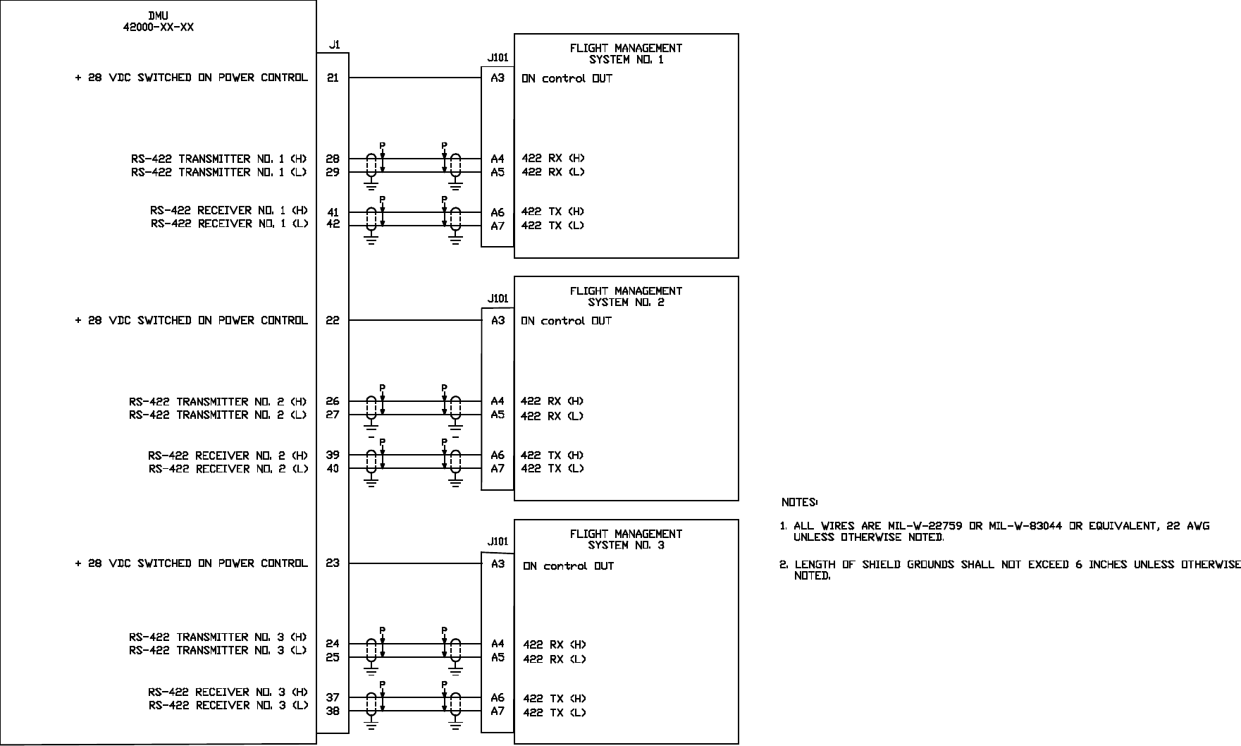
Transmitter designation applies to the signal function for that unit. Example, a DMU transmitter (H)
and (L) will connect to a DTU receiver (H) and (L).
All signal and power shields are to be grounded at one end, preferably at the point of origination
and shield continuity shall be maintained through bulkhead disconnects.
All digital data shields are to be grounded at both ends and shield continuity shall be maintained
through bulkhead disconnects.
NOTE:
This equipment has been designed to be installed in aircraft locations where it is
not subjected to falling water (generally the result of condensation), rain, or
sprayed water in the course of normal aircraft operations.
Global
AIRBORNE FLIGHT INFORMATION SYSTEM
IMAFISJWA 3-2
March/2001
THIS PAGE IS RESERVED
Global
AIRBORNE FLIGHT INFORMATION SYSTEM
IMAFISJWA 3-3
March/2001
DMU FUEL FLOW WIRING USING ELDEC INDICATOR
Dwg. No. 155-01712-4001 Rev 0
Figure 3-1
Global
AIRBORNE FLIGHT INFORMATION SYSTEM
IMAFISJWA 3-5
March/2001
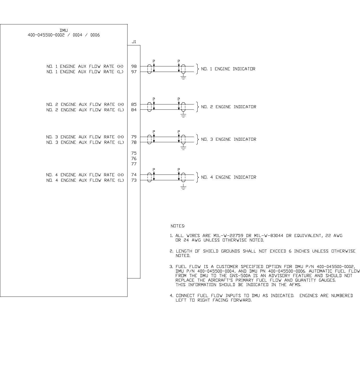
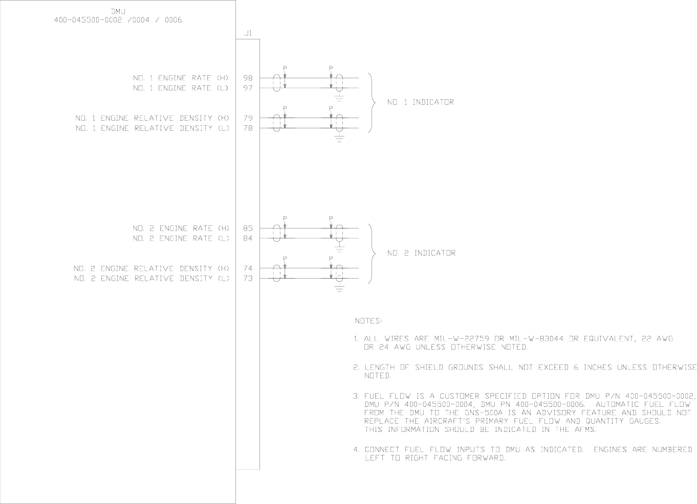
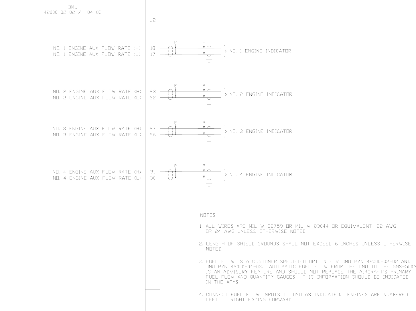
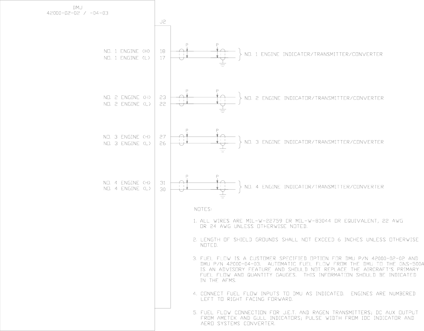
DMU FUEL FLOW WIRING FOR VARIOUS INDICATORS (see note 5)
Dwg. No. 155-01712-4002 Rev A
Figure 3-2
Global
AIRBORNE FLIGHT INFORMATION SYSTEM
IMAFISJWA 3-7
March/2001
DMU FUEL FLOW INTERTECHNIQUE
Dwg. No. 155-01712-4003 Rev A
Figure 3-3
Global
AIRBORNE FLIGHT INFORMATION SYSTEM
IMAFISJWA 3-9
March/2001
DMU FUEL FLOW GE 5 VRMS AC
Dwg. No. 155-01712-4004 Rev A
Figure 3-4
Global
AIRBORNE FLIGHT INFORMATION SYSTEM
IMAFISJWA 3-11
March/2001
DMU FUEL FLOW Eldec Transmitter As Source
Dwg. No. 155-01712-4005 Rev A
Figure 3-5
Global
AIRBORNE FLIGHT INFORMATION SYSTEM
IMAFISJWA 3-13
March/2001
DMU TO TRIPLE PORT DTU
Dwg. No. 155-01712-4006 Rev 0
Figure 3-6
Global
AIRBORNE FLIGHT INFORMATION SYSTEM
IMAFISJWA 3-15
March/2001
DMU TO DTU PN 43000-01-01-3 and PN 43000-01-01-4
Dwg. No. 155-01712-4007 Rev A
Figure 3-7
Global
AIRBORNE FLIGHT INFORMATION SYSTEM
IMAFISJWA 3-17
March/2001
DMU TO DTU PN 43000-01-01-1 and PN 43000-01-01-2
Dwg. No. 155-01712-4008 Rev 0
Figure 3-8
Global
AIRBORNE FLIGHT INFORMATION SYSTEM
IMAFISJWA 3-19
March/2001
DMU TO NMU GNS-X
Dwg. No. 155-01712-4009 Rev C
Figure 3-9 (Sheet 1 of 7)
Global
AIRBORNE FLIGHT INFORMATION SYSTEM
IMAFISJWA 3-21
March/2001
DMU TO GNS-XLS
Dwg. No. 155-01712-4009 Rev C
Figure 3-9 (Sheet 2 of 7)
Global
AIRBORNE FLIGHT INFORMATION SYSTEM
IMAFISJWA 3-23
March/2001
DMU TO GNS XL
Dwg. No. 155-01712-4009 Rev C
Figure 3-9 (Sheet 3 of 7)
Global
AIRBORNE FLIGHT INFORMATION SYSTEM
IMAFISJWA 3-25
March/2001
DMU TO Honeywell FMS NZ-2000
Dwg. No. 155-01712-4009 Rev C
Figure 3-9 (Sheet 4 of 7)

Global
AIRBORNE FLIGHT INFORMATION SYSTEM
IMAFISJWA 3-27
March/2001
DMU TO Honeywell FMS IAC (F-900 EX)
Dwg. No. 155-01712-4009 Rev C
Figure 3-9 (Sheet 5 of 7)
Global
AIRBORNE FLIGHT INFORMATION SYSTEM
IMAFISJWA 3-29
March/2001
DMU TO COLLINS FMS
Dwg. No. 155-01712-4009 Rev C
Figure 3-9 (Sheet 6 of 7)
Global
AIRBORNE FLIGHT INFORMATION SYSTEM
IMAFISJWA 3-31
March/2001
DMU TO UNIVERSAL FMC UNS-1C
Dwg. No. 155-01712-4009 Rev C
Figure 3-9 (Sheet 7 of 7)
Global
AIRBORNE FLIGHT INFORMATION SYSTEM
IMAFISJWA 3-33
March/2001
CDU-XLS TO AFIS INTERFACE
Dwg. No. 155-01657-0000 Rev -
Figure 3-9A (Sheet 1 of 2)
Global
AIRBORNE FLIGHT INFORMATION SYSTEM
IMAFISJWA 3-35
March/2001
CDU-XLS TO AFIS INTERFACE
Dwg. No. 155-01657-0000 Rev -
Figure 3-9A (Sheet 2 of 2)
Global
AIRBORNE FLIGHT INFORMATION SYSTEM
IMAFISJWA 3-37
March/2001
DMU TO FMC GNS-500A SERIES 4/5
Dwg. No. 155-01712-4010 Rev 0
Figure 3-10
Global
AIRBORNE FLIGHT INFORMATION SYSTEM
IMAFISJWA 3-39
March/2001
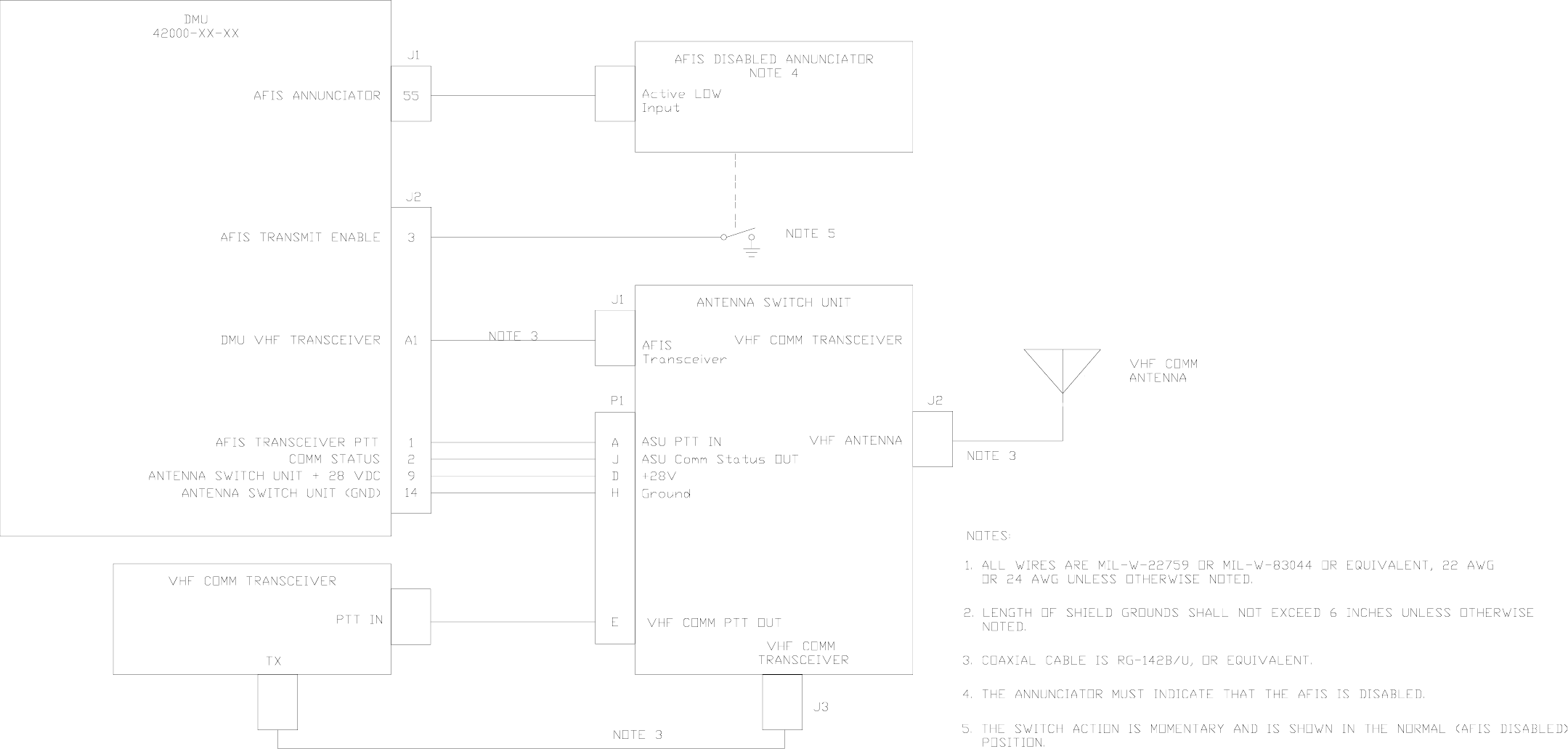
DMU TO SWITCHED AFIS ANTENNA
Dwg. No. 155-01712-4011 Rev A
Figure 3-11
Global
AIRBORNE FLIGHT INFORMATION SYSTEM
IMAFISJWA 3-41
March/2001
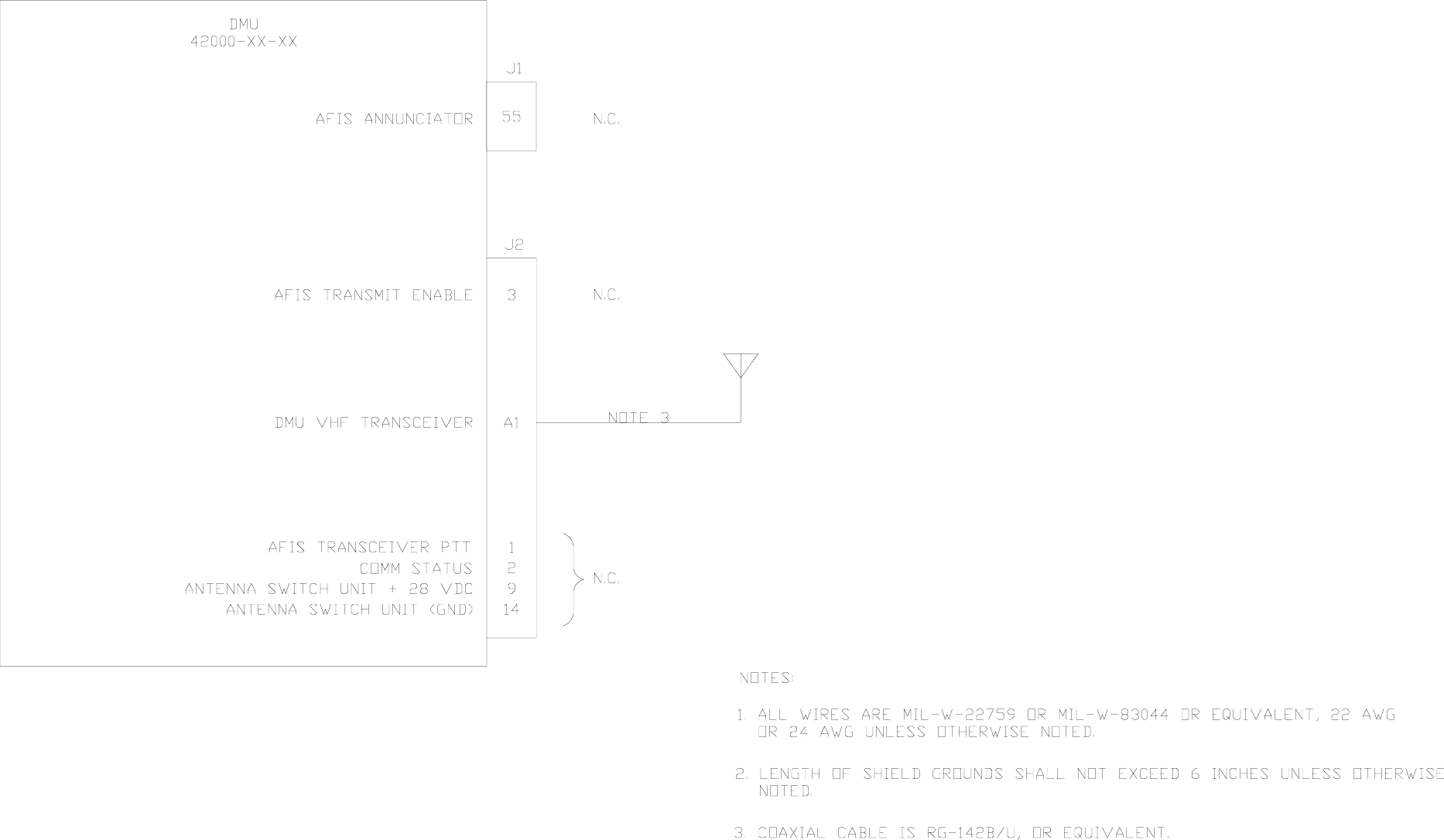
DMU TO DEDICATED AFIS ANTENNA
Dwg. No. 155-01712-4012 Rev 0
Figure 3-12
Global
AIRBORNE FLIGHT INFORMATION SYSTEM
IMAFISJWA 3-43
March/2001
DMU TO PRINTERS AND TERMINALS
Dwg. No. 155-01712-4013 Rev A
Figure 3-13
Global
AIRBORNE FLIGHT INFORMATION SYSTEM
IMAFISJWA 3-45
March/2001
DMU TO CONFIGURATION MODULE AND SATFONE SYSTEM
Dwg. No. 155-01712-4014 Rev B
Figure 3-14
Global
AIRBORNE FLIGHT INFORMATION SYSTEM
IMAFISJWA 3-47
March/2001
DMU TO SCU
Dwg. No. 155-01712-4015 Rev B
Figure 3-15 (Sheet 1 of 2)
Global
AIRBORNE FLIGHT INFORMATION SYSTEM
IMAFISJWA 3-49
March/2001
DMU TO SCU
Dwg. No. 155-01712-4015 Rev B
Figure 3-15 (Sheet 2 of 2)
Global
AIRBORNE FLIGHT INFORMATION SYSTEM
IMAFISJWA 3-51
March/2001
DISCRETE WIRING
Dwg. No. 155-01712-4016 Rev 0
Figure 3-16
Global
AIRBORNE FLIGHT INFORMATION SYSTEM
IMAFISJWA 3-53
March/2001
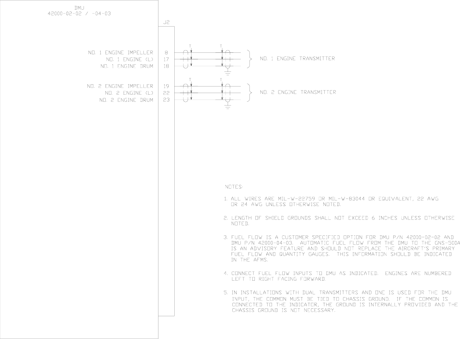
DMU FUEL FLOW WIRING USING ELDEC INDICATOR
Dwg. No. 155-01711-0001 Rev A
Figure 3-17
Global
AIRBORNE FLIGHT INFORMATION SYSTEM
IMAFISJWA 3-55
March/2001
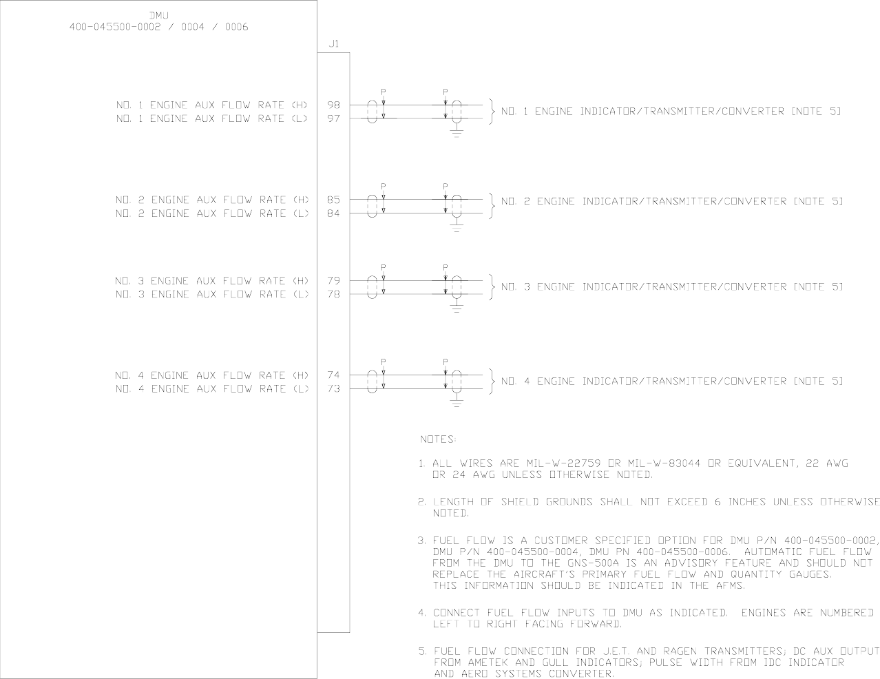
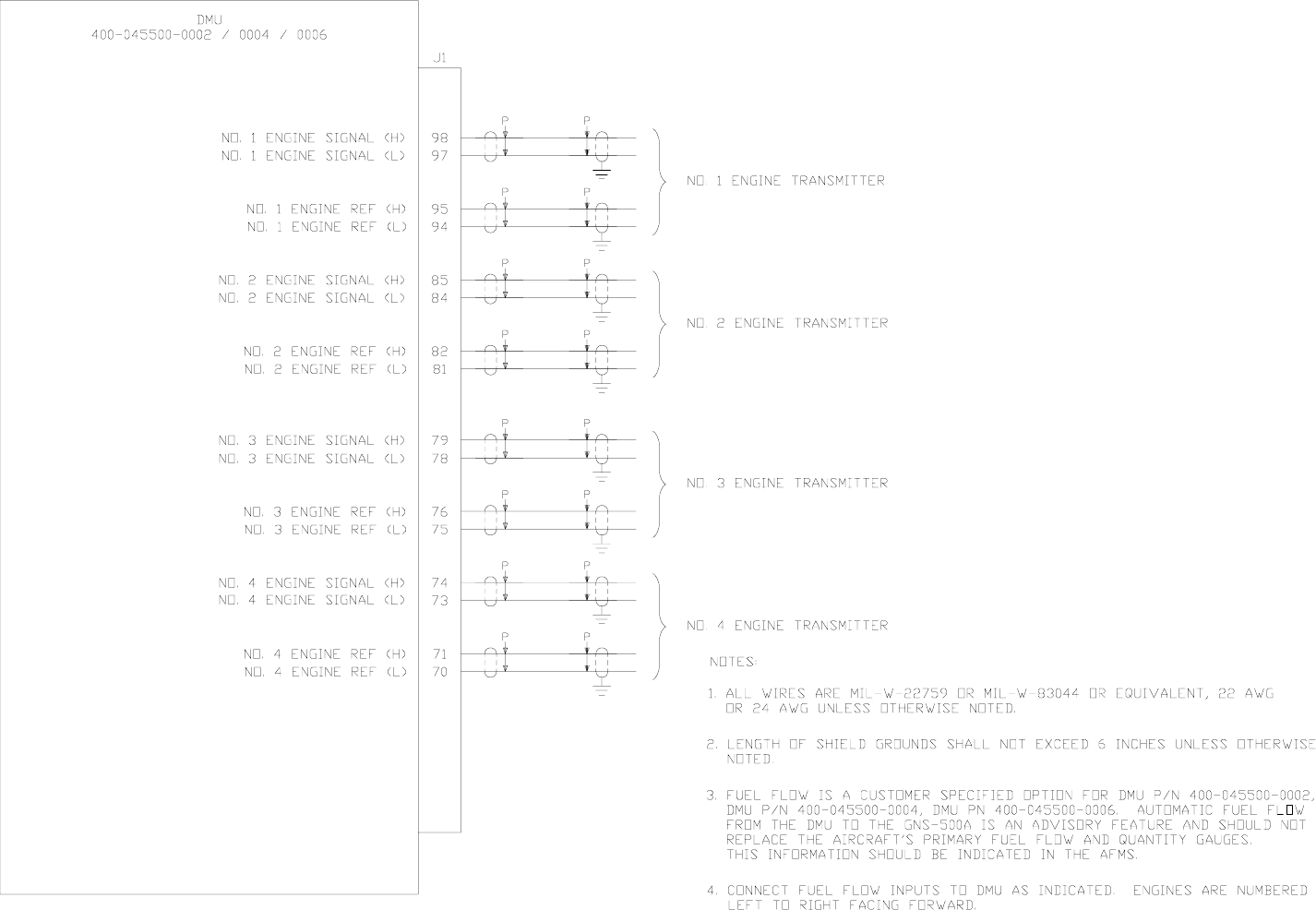
DMU FUEL FLOW WIRING For Various Indicators (see note 5)
Dwg. No. 155-01711-0002 Rev A
Figure 3-18
Global
AIRBORNE FLIGHT INFORMATION SYSTEM
IMAFISJWA 3-57
March/2001
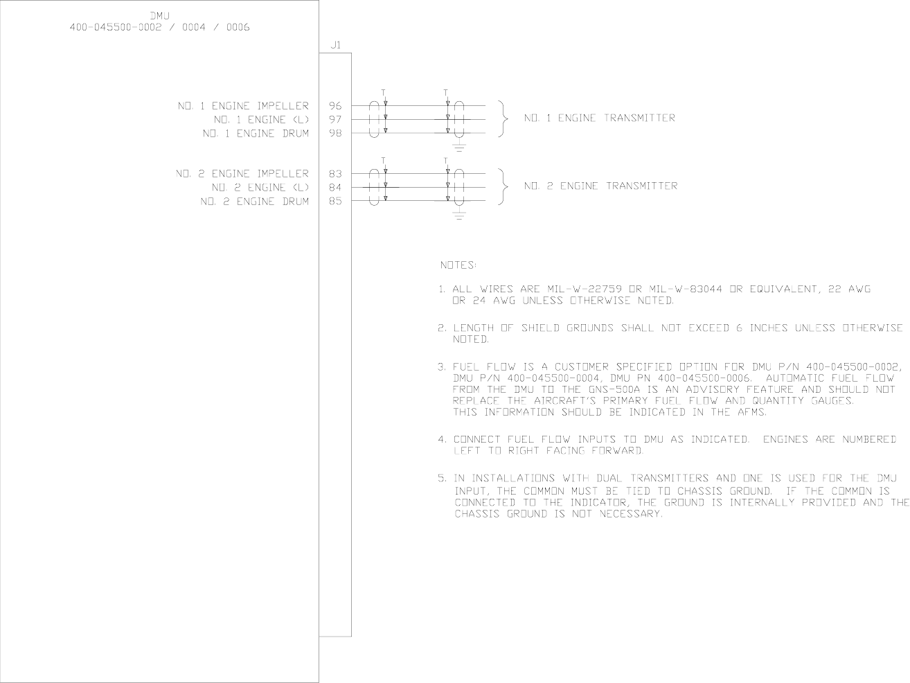
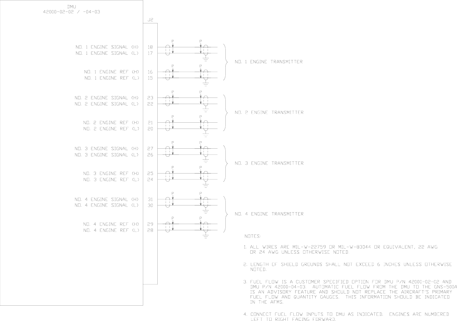
DMU FUEL FLOW INTERTECHNIQUE
Dwg. No. 155-01711-0003 Rev A
Figure 3-19
Global
AIRBORNE FLIGHT INFORMATION SYSTEM
IMAFISJWA 3-59
March/2001
DMU FUEL FLOW GE 5 VRMS AC
Dwg. No. 155-01711-0004 Rev A
Figure 3-20
Global
AIRBORNE FLIGHT INFORMATION SYSTEM
IMAFISJWA 3-61
March/2001
DMU FUEL FLOW ELDEC TRANSMITTER AS SOURCE
Dwg. No. 155-01711-0005 Rev A
Figure 3-21

Global
AIRBORNE FLIGHT INFORMATION SYSTEM
IMAFISJWA 3-63
March/2001
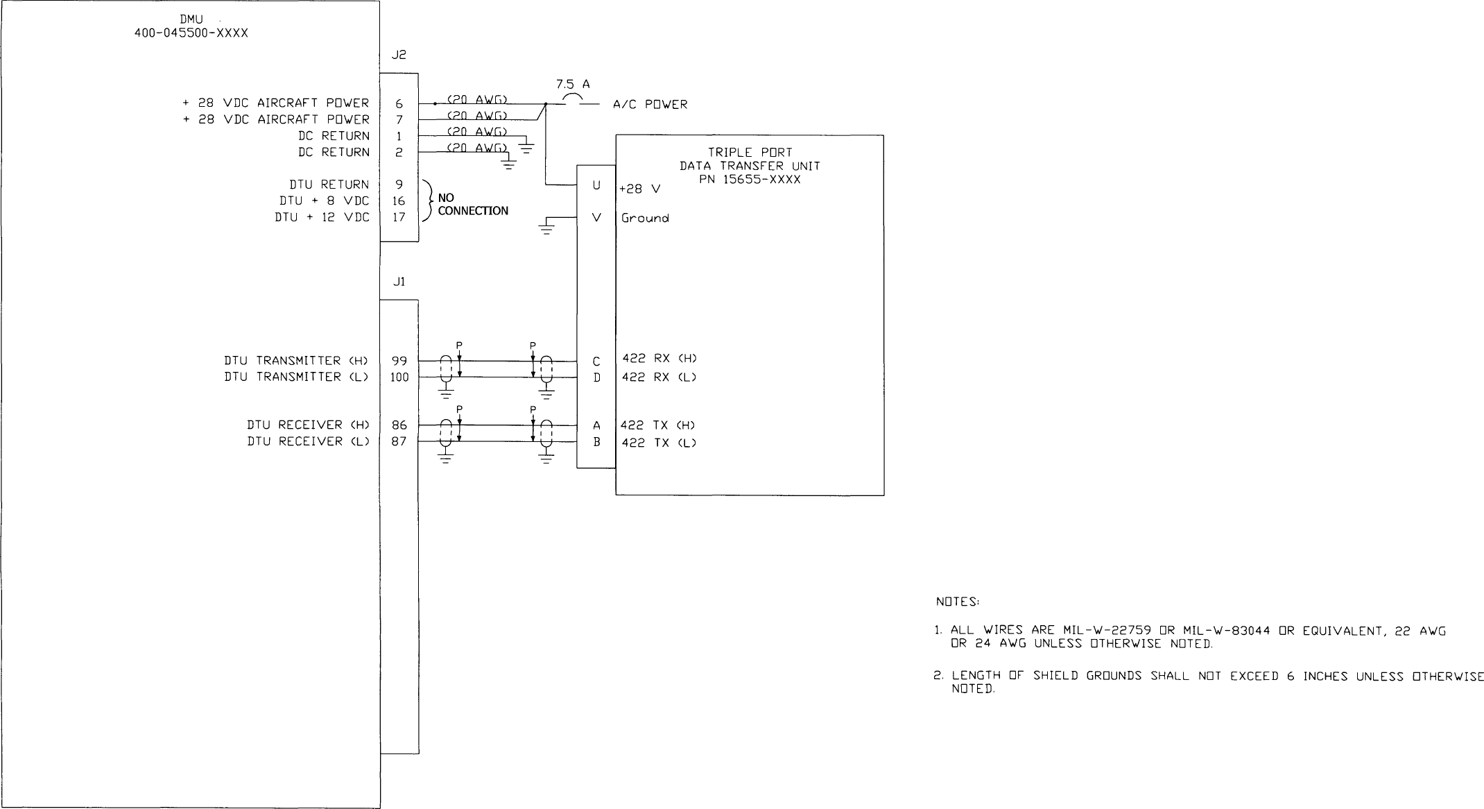
DMU TO TRIPLE PORT DTU PN 15655-XXXX
Dwg. No. 155-01711-0006 Rev 0
Figure 3-22
Global
AIRBORNE FLIGHT INFORMATION SYSTEM
IMAFISJWA 3-65
March/2001
Dwg. No. 155-01711-0007 Rev 0
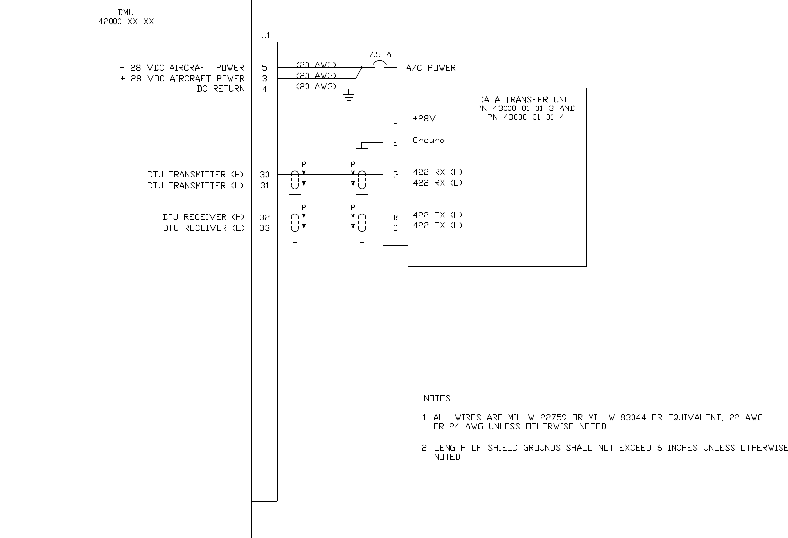
DMU TO DTU PN 43000-01-01-3 AND PN 43000-01-01-4
Figure 3-23
Global
AIRBORNE FLIGHT INFORMATION SYSTEM
IMAFISJWA 3-67
March/2001
Dwg. No. 155-01711-0008 Rev 0
DMU TO DTU PN 43000-01-01-1 AND PN 43000-01-01-2
Figure 3-24
Global
AIRBORNE FLIGHT INFORMATION SYSTEM
IMAFISJWA 3-69
March/2001
DMU TO FMC GNS-1000
Dwg. No. 155-01711-0009 Rev B
Figure 3-25 (Sheet 1 of 4)
Global
AIRBORNE FLIGHT INFORMATION SYSTEM
IMAFISJWA 3-71
March/2001
DMU TO NMU GNS-X
Dwg. No. 155-01711-0009 Rev B
Figure 3-25 (Sheet 2 of 4)
Global
AIRBORNE FLIGHT INFORMATION SYSTEM
IMAFISJWA 3-73
March/2001
DMU TO GNS-XLS
Dwg. No. 155-01711-0009 Rev B
Figure 3-25 (Sheet 3 of 4)
Global
AIRBORNE FLIGHT INFORMATION SYSTEM
IMAFISJWA 3-75
March/2001
DMU TO GNS-XL
Dwg. No. 155-01711-0009 Rev B
Figure 3-25 (Sheet 4 of 4)
Global
AIRBORNE FLIGHT INFORMATION SYSTEM
IMAFISJWA 3-77
March/2001
DMU TO GNS-500A SERIES 4
Dwg. No. 155-01711-0010 Rev B
Figure 3-26
Global
AIRBORNE FLIGHT INFORMATION SYSTEM
IMAFISJWA 3-79
March/2001
DMU TO SWITCHED AFIS ANTENNA
Dwg. No. 155-01711-0011 Rev A
Figure 3-27
Global
AIRBORNE FLIGHT INFORMATION SYSTEM
IMAFISJWA 3-81
March/2001
DMU TO DEDICATED AFIS ANTENNA
Dwg. No. 155-01711-0012 Rev A
Figure 3-28
Global
AIRBORNE FLIGHT INFORMATION SYSTEM
IMAFISJWA 3-83
March/2001
DMU TO PRINTERS AND TERMINALS
Dwg. No. 155-01711-0013 Rev A
Figure 3-29
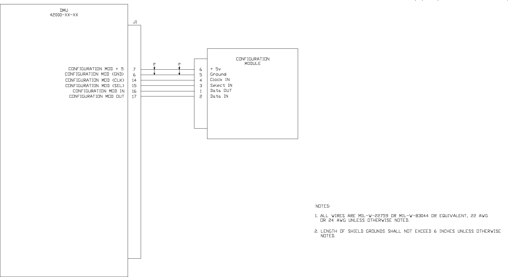
Global
AIRBORNE FLIGHT INFORMATION SYSTEM
IMAFISJWA 3-85
March/2001
DMU TO CONFIGURATION MODULE
Dwg. No. 155-01711-0014 Rev 0
Figure 3-30
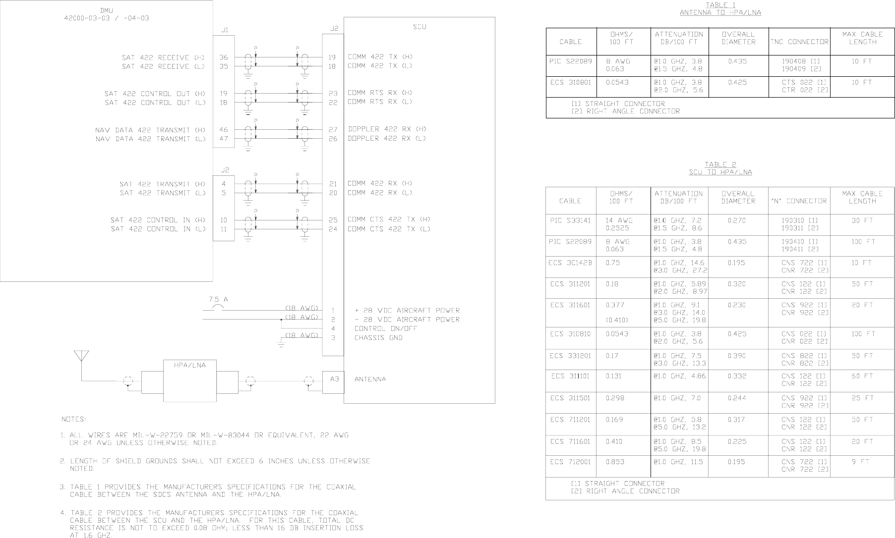
Global
AIRBORNE FLIGHT INFORMATION SYSTEM
IMAFISJWA 3-87
March/2001
Dwg. No. 155-01711-0015 Rev A
DMU TO SCU
Figure 3-31 (Sheet 1 of 2)
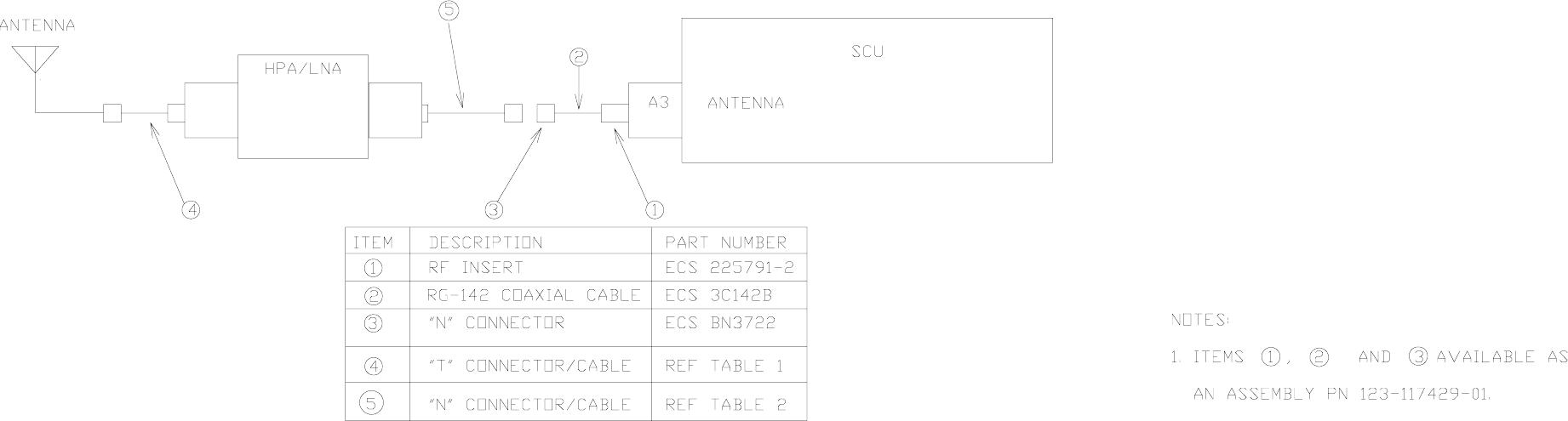
Global
AIRBORNE FLIGHT INFORMATION SYSTEM
IMAFISJWA 3-89
March/2001
DMU TO SCU
Dwg. No. 155-01711-0015 Rev A
Figure 3-31 (Sheet 2 of 2)
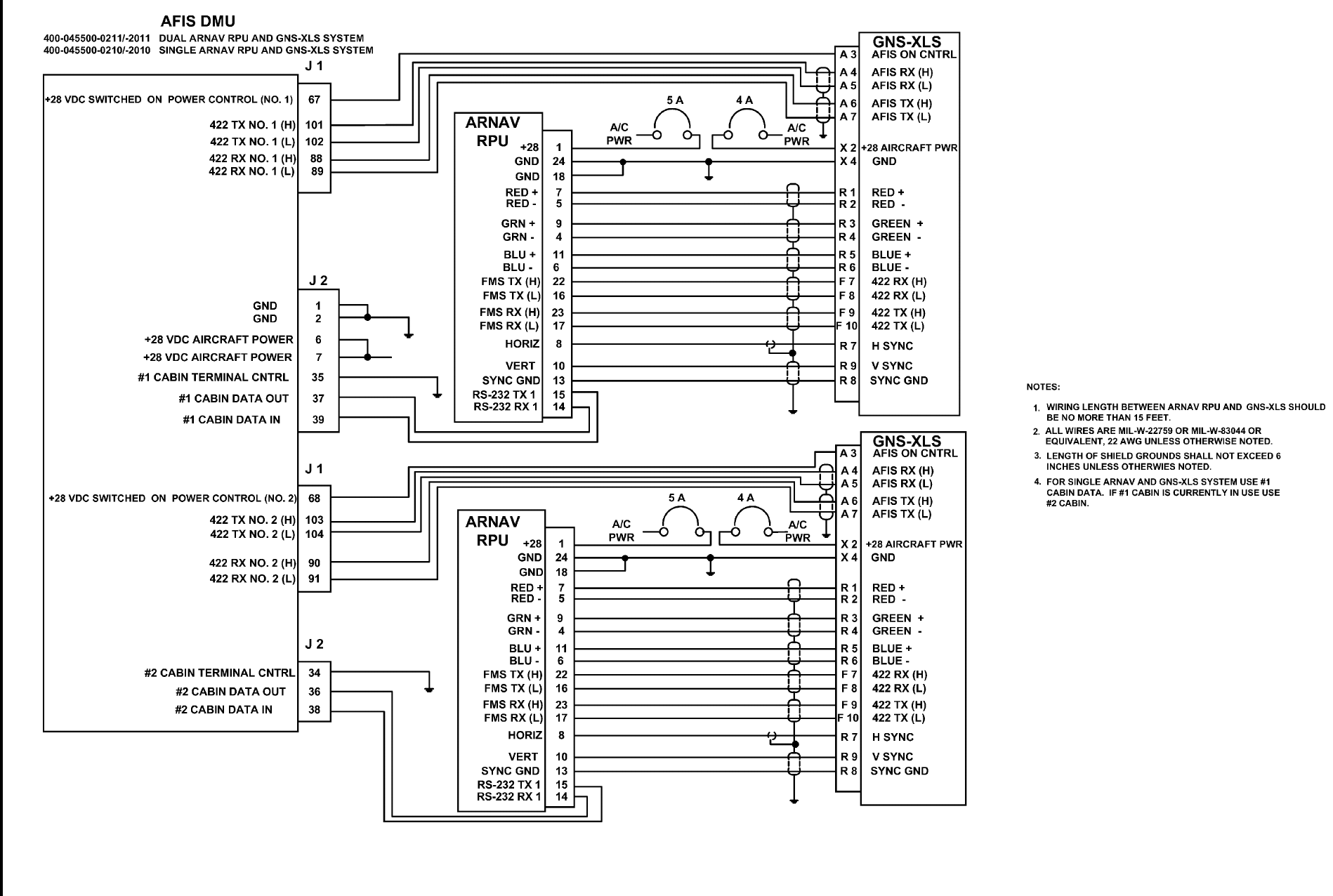
Global
AIRBORNE FLIGHT INFORMATION SYSTEM
IMAFISJWA 3-91
March/2001
DMU TO ARNAV RPU AND GNS-XLS WIRING DIAGRAM
DWG NO. 155-01712-4017, Rev. C
Figure 3-32
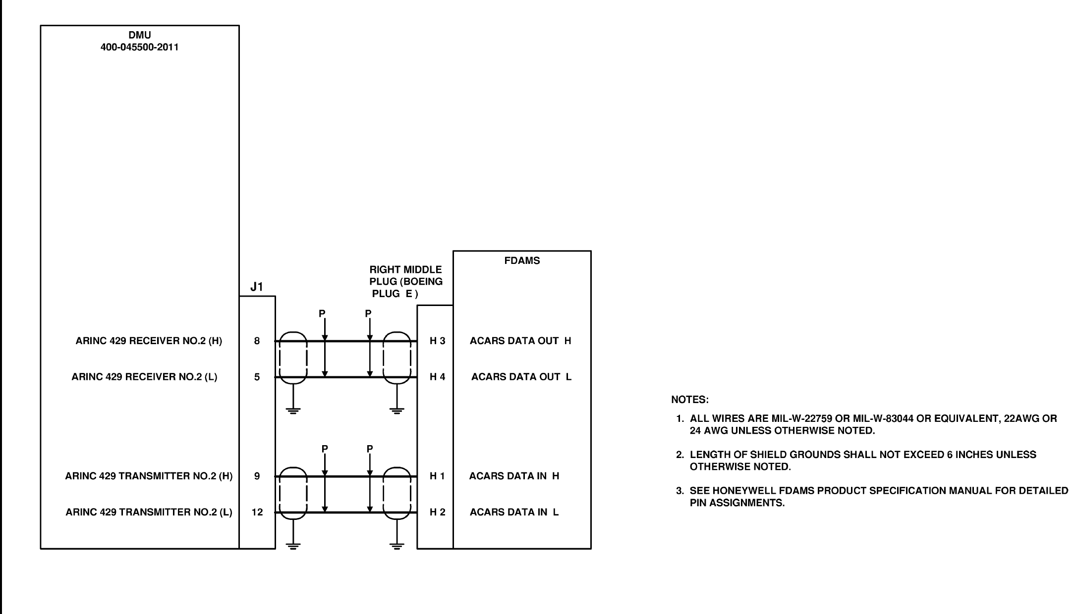
Global
AIRBORNE FLIGHT INFORMATION SYSTEM
IMAFISJWA 3-93
March/2001
DMU TO FLIGHT DATA ACQUISITION AND MANAGEMENT SYSTEM (FDAMS)
DWG NO. 155-01712-4018
Figure 3-32A
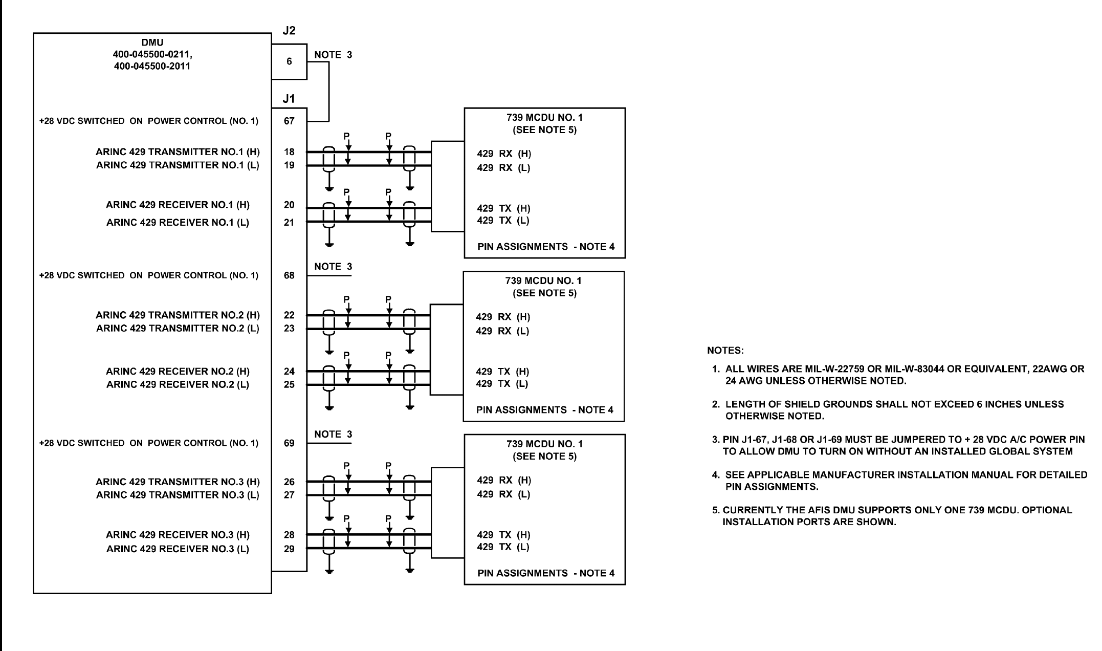
Global
AIRBORNE FLIGHT INFORMATION SYSTEM
IMAFISJWA 3-95
March/2001
DMU TO 739 MCDU
DWG NO. 155-01712-4019 R-
Figure 3-32B
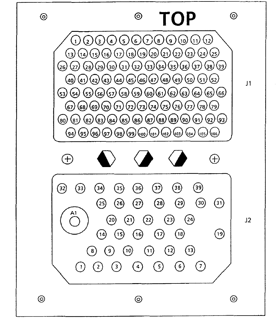
Global
AIRBORNE FLIGHT INFORMATION SYSTEM
IMAFISJWA 3-97
March/2000
DMU Unit Connector PN 400-045500-XXXX
Figure 3-33 (Sheet 1 of 3)
Global
AIRBORNE FLIGHT INFORMATION SYSTEM
IMAFISJWA 3-98
March/2000
THIS PAGE IS RESERVED

Global
AIRBORNE FLIGHT INFORMATION SYSTEM
IMAFISJWA 3-99
March/2001
DMU CONNECTOR J1 PN 400-045500-XXXX
Figure 3-33 (Sheet 2 of 3)
PIN SIGNAL NAME PIN SIGNAL NAME PIN SIGNAL NAME PIN SIGNAL NAME PIN SIGNAL NAME
1Config MOD CLK 23 429 TX No.2 (L) 45 Spare 67 +28V Switched ON 86 DTU RX (H)
2Config MOD SEL. 24 429 RX No.2 (H) 46 Spare POWER CONTROL 87 DTU RX (L)
3Config MOD DATA IN 25 429 RX No.2 (L) 47 422 NAV SAT TX (H) 68 +28V Switched ON 88 422 RX No.1 (H)
4Config MOD DATA OUT 26 429 TX No.3 (H) 48 422 NAV SAT TX (L) POWER CONTROL 89 422 RX No.1 (L)
5429 ACMS RX - 2(L) 27 429 TX No.3 (L) 49 Spare 69 +28V Switched ON 90 422 RX No.2 (H)
6429 SDU TX (H) 28 429 RX No.3 (H) 50 Spare POWER CONTROL 91 422 RX No.2 (L)
7429 SDU TX (L) 29 429 RX No.3 (L) 51 Spare 70 No. 4 Engine 92 422 RX No.3 (H)
8429 ACMS RX - 2(H) 30 Discrete 1 52 Spare 71 No. 4 Engine 93 422 RX No.3 (L)
9429 ACMS TX - 2(H) 31 Discrete 2 53 Spare 72 No. 4 Engine 94 No. 1 Engine
10 429 SDU RX (H) 32 Discrete 3 54 Spare 73 No. 4 Engine 95 No. 1 Engine
11 429 SDU RX (L) 33 Discrete Brake Release 55 Spare 74 No. 4 Engine 96 No. 1 Engine
12 429 ACMS TX - 2(L) 34 Discrete Engine Stop SW 56 Spare 75 No. 3 Engine 97 No. 1 Engine
13 Spare 35 Discrete Oil Pressure 57 Spare 76 No. 3 Engine 98 No. 1 Engine
14 Spare 36 Door Closure 58 Spare 77 No. 3 Engine 99 DTU TX (H)
15 Spare 37 Discrete 8 59 Spare 78 No. 3 Engine 100 DTU TX (L)
16 Spare 38 Discrete COMM Status 60 Spare 79 No. 3 Engine 101 422 TX No.1 (H)
17 #2 Printer Control IN 39 AFIS Transmit Enable 61 Spare 80 AFIS ANNUNCIATOR 102 422 TX No.1 (L)
18 429 TX No.1 (H) 40 Discrete Weight on Wheels 62 Spare 81 No. 2 Engine 103 422 TX No.2 (H)
19 429 TX No.1 (L) 41 ASU PTT 63 Spare 82 No. 2 Engine 104 422 TX No.2 (L)
20 429 RX No.1 (H) 42 AFIS Annunciator 64 Spare 83 No. 2 Engine 105 422 TX No.3 (H)
21 429 RX No.1 (L) 43 Spare 65 Spare 84 No. 2 Engine 106 422 TX No.3 (L)
22 429 TX No.2 (H) 44 Spare 66 Spare 85 No. 2 Engine

Global
AIRBORNE FLIGHT INFORMATION SYSTEM
IMAFISJWA 3-101
March/2000
NOTE
Printer and Cabin Terminal lines are RS232. “IN” and “OUT” are in respect to the DMU
DMU Connector J2 PN 400-045500-XXXX
Figure 3-33 (Sheet 3 of 3)
PIN SIGNAL NAME PIN SIGNAL NAME
A1 DMU VHF TRANSCEIVER (ANT.) 20 PRINTER DATA RETURN (L)
1DC RETURN 21 PRINTER DATA OUT (H)
2DC RETURN 22 PRINTER DTR RETURN(L)
3SPARE 23 PRINTER DTR IN (H)
4#2 PRINTER DATA OUT 24 SPARE
5SPARE 25 SPARE
6+ 28V AIRCRAFT POWER 26 422 SAT TX (H)
7+ 28V AIRCRAFT POWER 27 422 SAT TX (L)
8CONFIG MOD GROUND 28 422 SAT RX (H)
9DTU DC RETURN 29 422 SAT RX (L)
10 ANTENNA SWITCH UNIT (GND) 30 422 SAT CONTROL OUT (H)
11 SPARE 31 422 SAT CONTROL OUT (L)
12 SPARE 32 422 SAT CONTROL IN (H)
13 + 28V ANTENNA SWITCH UNIT 33 422 SAT CONTROL IN (L)
14 + 28V SHIELD 34 #2 CABIN TERMINAL CNTL IN / GND
FOR GRAPHICS
15 + 5V FOR CONFIG MOD 35 #1 CABIN TERMINAL CNTL IN / GND
FOR GRAPHICS
16 + 8VDC DTU FILTERED 36 #2 CABIN DATA / ARNAV RPU OUT
17 + 12VDC DTU FILTERED 37 #1 CABIN DATA / ARNAV RPU OUT
18 SPARE 38 #2 CABIN DATA / ARNAV RPU IN
19 SPARE 39 #1 CABIN DATA / ARNAV RPU IN
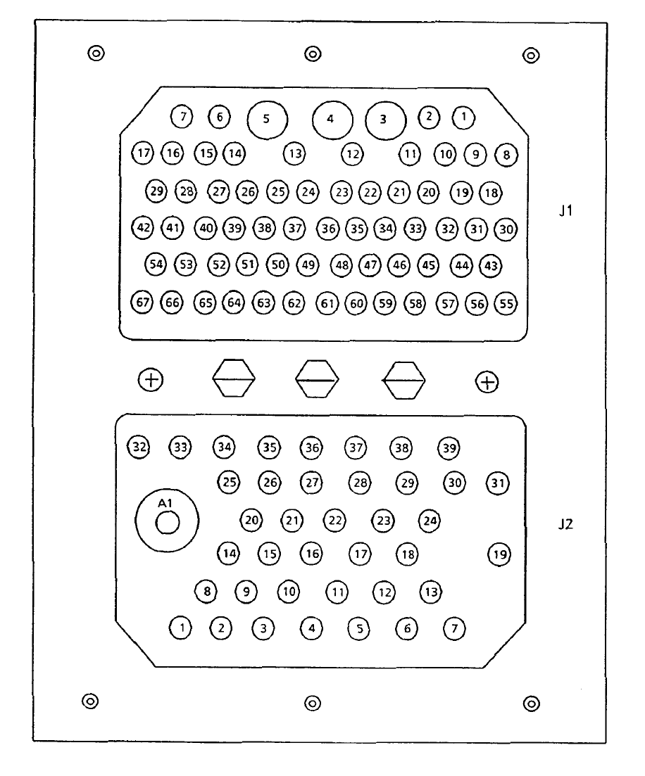
Global
AIRBORNE FLIGHT INFORMATION SYSTEM
IMAFISJWA 3-102
March/2000
DMU Connector PN 42000-XX-XX
Figure 3-34 (Sheet 1 of 3)

Global
AIRBORNE FLIGHT INFORMATION SYSTEM
IMAFISJWA 3-103
March/2000
DMU CONNECTOR J1 PN 42000-XX-XX
Figure 3-34 (Sheet 2 of 3)
PIN SIGNAL NAME PIN SIGNAL NAME
1 NC 35 422 SAT RX (L)
2 Spare 36 422 SAT RX (H)
3 + 28V AIRCRAFT Power 37 422 No.3 RX (H)
4 DC RETURN 38 422 No.3 RX (L)
5 +28V AIRCRAFT Power 39 422 No.2 RX (H)
6 Conf. MOD (Ground) 40 422 No.2 RX (HL
7 Conf. MOD + 5VDC 41 422 No.1 RX (H)
8 DTU Return 42 422 No.1 RX (L)
9 DTU +8VDC 43 #2 Cabin Data OUT
10 DTU +12VDC 44 NC
11 #1 Cabin Data IN 45 NC
12 #1 Cabin Data OUT 46 NAV Data TX (H)
13 #1 Cabin Terminal Control IN 47 NAV Data TX (L)
14 Config. MOD CLK 48 Printer Data Out RS 232
15 Config. MOD SEL 49 Printer CNTL IN RS 232
16 Config. MOD IN 50 SPARE 429 TX (H)
17 Config. MOD OUT 51 SPARE 429 TX (L)
18 422 SAT Cntl OUT (L) 52 NC
19 422 SAT Cntl OUT (H) 53 VHF AUDIO IN (H)
20 #2 Printer CNTL IN 54 VHF AUDIO IN (L)
21 ON Control No.1 55 AFIS ANNUNCIATOR
22 ON Control No.2 56 #2 Printer Data OUT
23 ON Control No.3 57 NC
24 422 No.3 TX (H) 58 NC
25 422 No.3 TX (L) 59 SPARE 422 RX (H)
26 422 No.2 TX (H) 60 SPARE 422 RX (L)
27 422 No.2 TX (L) 61 VHF Audio OUT (H)
28 422 No.1 TX (H) 62 VHF Audio OUT (L)
29 422 No.1 TX (L) 63 SPARE 429 RX (H)
30 DTU Transmit (H) 64 SPARE 429 RX (L)
31 DTU Transmit (L) 65 NC
32 DTU RCVR (H) 66 NC
33 DTU RCVR (L) 67 NC
34 WEIGHT ON GEAR

Global
AIRBORNE FLIGHT INFORMATION SYSTEM
IMAFISJWA 3-104
March/2000
DMU Connector J2 PN 42000-XX-XX
Figure 3-34 (Sheet 3 of 3)
PIN SIGNAL NAME PIN SIGNAL NAME
A1 DMU VHF TRANSCEIVER 20 Fuel Flow ENGINE 2
1 AFIS TRANSCIEVER PTT 21 Fuel Flow ENGINE 2
2 PTT STATUS 22 Fuel Flow ENGINE 2
3 AFIS TRANSMIT ENABLE 23 Fuel Flow ENGINE 2
4 SAT 422 TX (H) 24 Fuel Flow ENGINE 3
5 SAT 422 TX (L) 25 Fuel Flow ENGINE 3
6 #2 Cabin Data IN 26 Fuel Flow ENGINE 3
7 #2 Cabin Terminal Control IN 27 Fuel Flow ENGINE 3
8 Fuel Flow Engine 1 28 Fuel Flow ENGINE 4
9 Antenna Switch Unit +28 VDC 29 Fuel Flow ENGINE 4
10 SAT 422 Control IN (H) 30 Fuel Flow ENGINE 4
11 SAT 422 Control IN (L) 31 Fuel Flow ENGINE 4
12 SPARE 422 RX (H) 32 NC
13 SPARE 422 RX (L) 33 NC
14 Antenna Switch Unit GROUND 34 NC
15 Fuel Flow ENGINE 1 35 NC
16 Fuel Flow ENGINE 1 36 NC
17 Fuel Flow ENGINE 1 37 NC
18 Fuel Flow ENGINE 1 38 NC
19 Fuel Flow ENGINE 2 39 NC
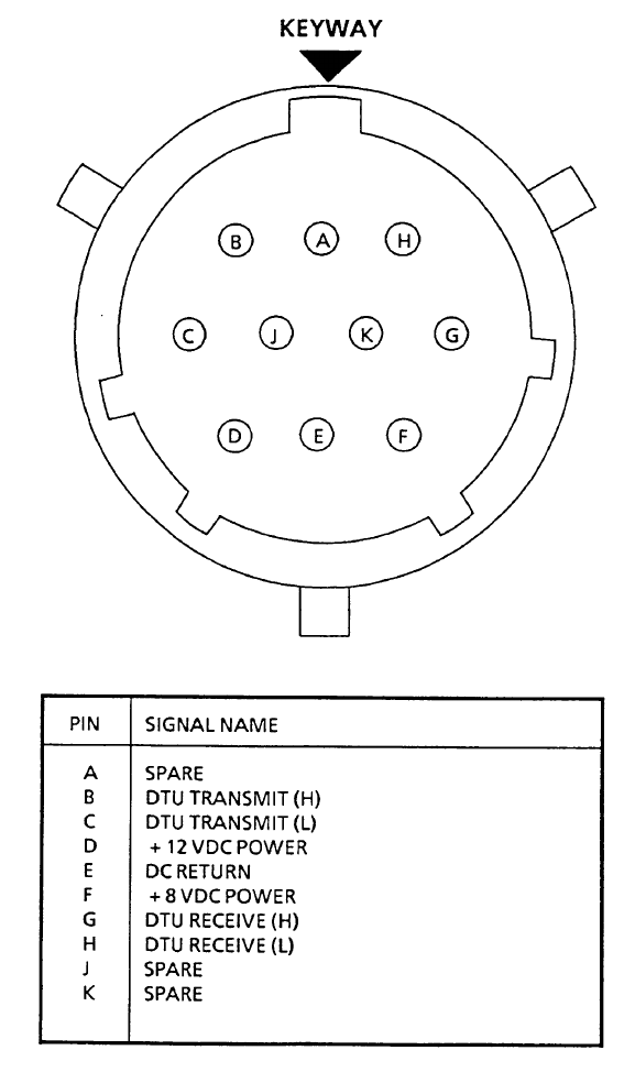
Global
AIRBORNE FLIGHT INFORMATION SYSTEM
IMAFISJWA 3-105
March/2000
DTU CONNECTOR PIN ASSIGNMENT
PN 43000-01-01-1 AND PN 43000-01-01-2
Figure 3-35
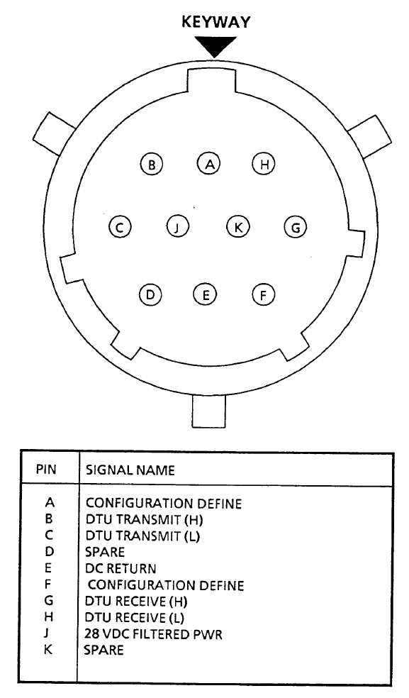
Global
AIRBORNE FLIGHT INFORMATION SYSTEM
IMAFISJWA 3-106
March/2000
DTU CONNECTOR PIN ASSIGNMENT
PN 43000-01-01-3 AND PN 43000-01-01-4
Figure 3-36
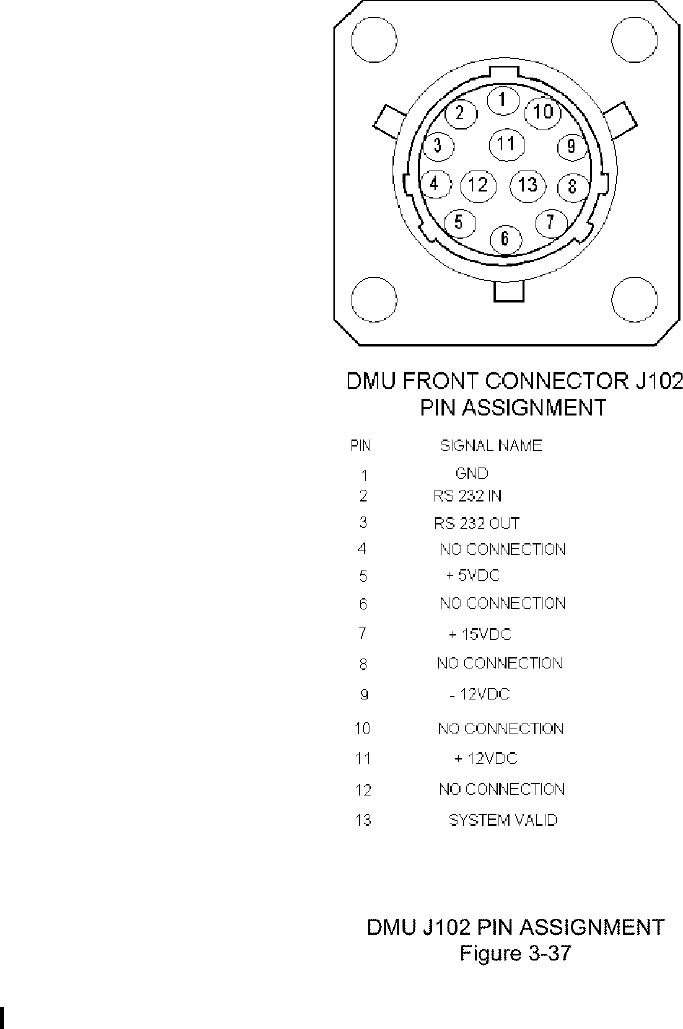
Global
AIRBORNE FLIGHT INFORMATION SYSTEM
IMAFISJWA 3-107
March/2000
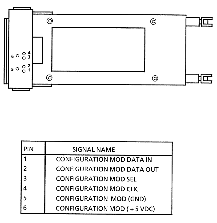
Global
AIRBORNE FLIGHT INFORMATION SYSTEM
IMAFISJWA 3-108
March/2000
CONFIGURATION MODULE CONNECTION
Figure 3-38
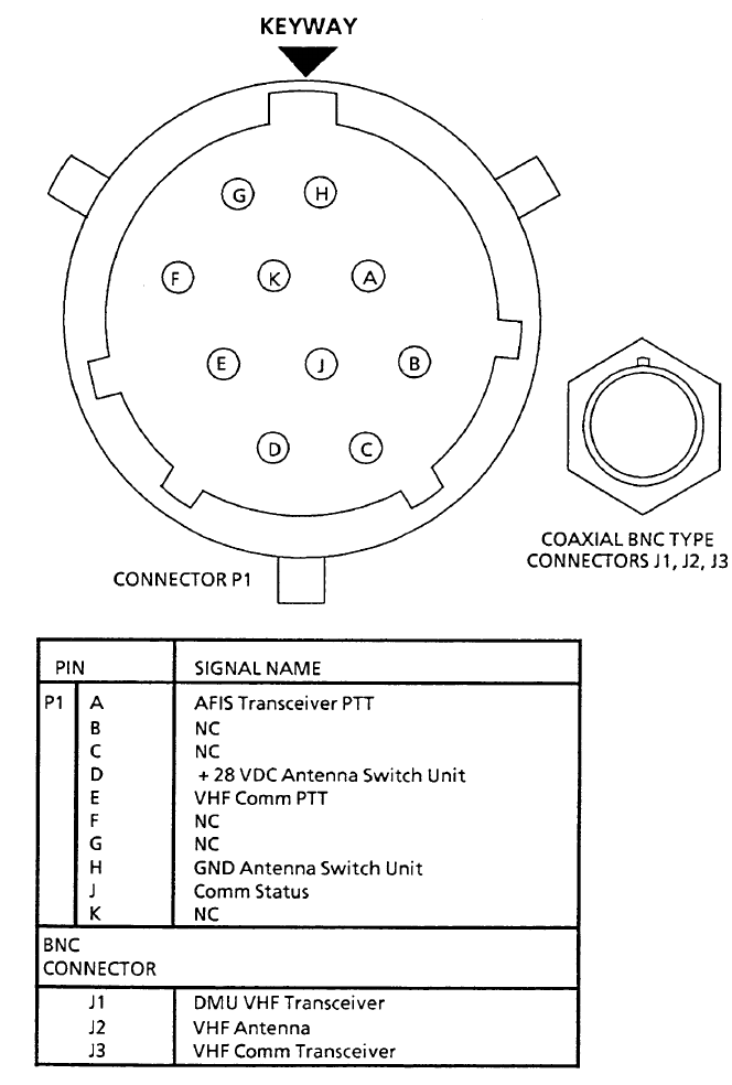
Global
AIRBORNE FLIGHT INFORMATION SYSTEM
IMAFISJWA 3-109
March/2000
ANTENNA SWITCHING UNIT PIN ASSIGNMENT
Figure 3-39
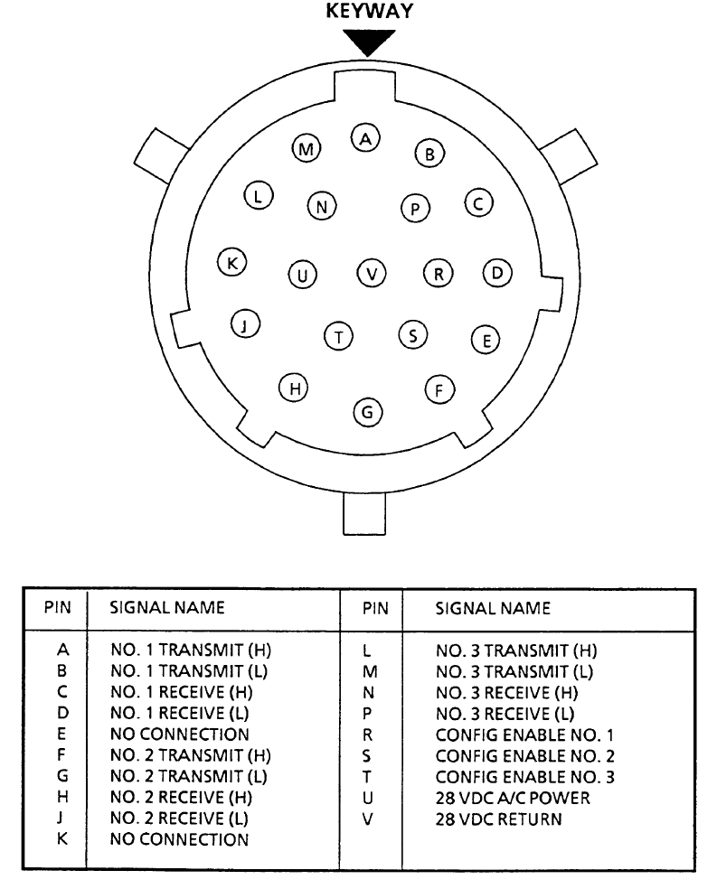
Global
AIRBORNE FLIGHT INFORMATION SYSTEM
IMAFISJWA 3-110
March/2000
TRIPLE PORT DTU CONNECTOR PIN ASSIGNMENT PN 15655-0X01
Figure 3-40
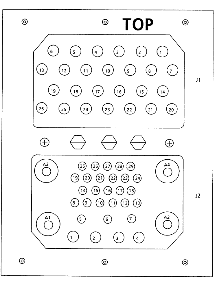
Global
AIRBORNE FLIGHT INFORMATION SYSTEM
IMAFISJWA 3-111
March/2000
SCU UNIT CONNECTOR
Figure 3-41 (Sheet 1 of 2)

Global
AIRBORNE FLIGHT INFORMATION SYSTEM
IMAFISJWA 3-112
March/2000
SCU Connector J1
SCU Connector J2
Figure 3-41 (Sheet 2 of 2)
PIN SIGNAL NAME PIN SIGNAL NAME
1 SPARE 14 SPARE
2 SPARE 15 SPARE
3 SPARE 16 SPARE
4 SPARE 17 SPARE
5 SPARE 18 SPARE
6 SPARE 19 SPARE
7 SPARE 20 SPARE
8 SPARE 21 SPARE
9 SPARE 22 SPARE
10 SPARE 23 SPARE
11 SPARE 24 SPARE
12 SPARE 25 SPARE
13 SPARE 26 SPARE
PIN SIGNAL NAME PIN SIGNAL NAME PIN SIGNAL NAME
1+ 28VDC AIRCRAFT POWER 12 SPARE 23 CONTROL IN (L)
2- 28VDC AIRCRAFT POWER 13 SPARE 24 CONTROL OUT (L)
3 Chassis Ground 14 SPARE 25 CONTROL OUT (H)
4 Control ON/OFF 15 SPARE 26 NAV Data (L)
5 SPARE 16 SPARE 27 NAV Data (H)
6 SPARE 17 SPARE 28 SPARE
7 SPARE 18 Data Transmit (L) 29 SPARE
8 SPARE 19 Data Transmit (H)
9 SPARE 20 Data Receive (L) A1 SPARE
10 SPARE 21 Data Receive (H) A2 SPARE
11 SPARE 22 CONTROL IN (H) A3 ANTENNA
A4 SPARE
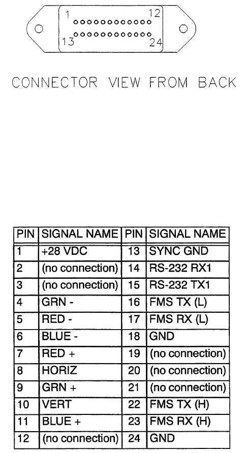
Global
AIRBORNE FLIGHT INFORMATION SYSTEM
IMAFISJWA 3-113
March/2000
Remote Processor Unit (RPU) Mating Connector
ARNAV P/N 150-1151
Figure 3-42 (Sheet 1 of 2)
Remote Processor Unit (RPU) Mating Connector
ARNAV P/N 150-1151
Figure 3-42 (Sheet 2 of 2)

Global
AIRBORNE FLIGHT INFORMATION SYSTEM
IMAFISJWA 3-114
March/2000
Connectors Used
Figure 3-43 (Sheet 1 of 2)
AFIS
COMPONENT
UNIT
CONNECTOR
MATING
CONNECTOR
DATA TRANSFER UNIT BURNDY BT02A-12-10P
BENDIX PT02A-12-10P
(Global P/N 12893-1)
BURNDY L12TF-10S-6NA
BENDIX PT06AC-12-10S
ITT KPT061312-10S
TRIPLE PORT DTU ITT KPT02A14-19P
BURNDY BT02A-14-19P
MIL-C-26482
MS3110E1419P
(Global P/N 129-215678-01)1
ITT KPT06F14-19S
BENDIX PT06CE-14-19S
DATA MANAGEMENT UNIT
P/N 400-045500-XXXX
ITT DPX2NA -A106S40W1MP-
34B-0144
VENDOR PN FOR RF
INSERT 249-2073-001
(Global P/N 129-214251-01)1
ITT DPX2NA-A106P40W1MS-
33B-0044
ITT PN FOR
RF INSERT 249-2078-001
P/N 42000-XX-XX ITT DPX2NA67MP40W1MP-
34B-01
VENDOR PN FOR RF
INSERT 249-2073-001
(Global P/N 42770-1)
ITT DPX2NA67MS40W1MS-
33B-00
ITT PN FOR
RF INSERT 249-2078-001
ANTENNA SWITCH UNIT
P1
BURNDY BT02A-12-10PW BURNDY
L12TF-10S-6WA
BT06AC12-10SW
Global PN 12893-2
J1,J2,J3 KINGS
KC-19-154
KINGS
KC-59-123
SATELLITE
COMMUNICATIONS UNIT (Global P/N 129-217338-01)1
AMP R2P26S33C4S0001(200)
AMPLIFIER (HPA/LNA) TNC TYPE WITH ECS 310801
N TYPE WITH RG 142
(Global P/N 129-017353-01
Straight)1
ECS CTS 022
(Global P/N 129-017353-02
Right Angle)1
ECS CTR 022
(Global P/N 129-017354-01
Straight)1
ECS CTS 722
(Global P/N 129-017354-02
Right Angle)1
ECS CTR 722

Global
AIRBORNE FLIGHT INFORMATION SYSTEM
IMAFISJWA 3-115
March/2000
Connectors Used
Figure 3-43 (Sheet 2 of 2)
AFIS
COMPONENT
UNIT
CONNECTOR
MATING
CONNECTOR
JET BLADE ANTENNA TNC TYPE WITH ECS 310801 (Global P/N 129-017353-01
Straight)1
ECS CTS 022
(Global P/N 129-017353-02
Right Angle)1
ECS CTR 022
LOW PROFILE
JET BLADE ANTENNA
TNC TYPE WITH ECS 310801 (Global P/N 129-017353-01
Straight)1
ECS CTS 022
(Global P/N 129-017353-02
Right Angle)1
ECS CTR 022
ARNAV REMOTE
PROCESSOR UNIT
CENTRONICS STYPE D SUB ARNAV P/N 150-11511
AMPHENOL 57-20240
1 Mating connectors with Global part numbers are the only connectors supplied by Honeywell.
Global
AIRBORNE FLIGHT INFORMATION SYSTEM
IMAFISJWA 3-116
March/2000
THIS PAGE IS RESERVED

Global
AIRBORNE FLIGHT INFORMATION SYSTEM
IMAFISJWA 3-117
March/2001
3.1 AFIS WX Display
AFIS DMU PN 400-045500-0210 or 400-045500-2010 are required to allow graphical weather to
be displayed. An ARNAV MFD 5115 RPU will be required to create the graphical images.
AFIS DMU PN 400-045500-0211 or 400-045500-2011 is required for Dual GNS-XLS graphical
weather display. An ARNAV MFD 5115 RPU will be required for each GNS-XLS to create the
graphical images.
AFIS DMU PN 400-045500-0003 or 400-045500-0005 will require software modification to allow
graphical weather to be displayed.
AFIS DMU PN 400-045500-0210 or 400-045500-2010 will require software modification to allow
Dual GNS-XLS graphical weather display.
Wiring between the GNS-XLS and AFIS DMU remains as defined in the present AFIS Installation
Manual.
Additional GNS-XLS pins for the AFIS weather graphics are as follows:
AFIS DMU pins for the weather graphics are as follows:
GNS-XLS TO RPU
J101-F7 WX RS422 Receive HI J101-R4 RGB Green LO
J101-F8 WX RS422 Receive LO J101-R5 RGB Blue HI
J101-F9 WX RS422 Transmit HI J101-R6 RGB Blue LO
J101-F10 WX RS422 Transmit LO J101-R7 RGB Horizontal Sync
J101-R1 RGB Red HI J101-R8 RGB Video Ground
J101-R2 RGB Red LO J101-R9 RGB Vertical Sync
J101-R3 RGB Green HI
FROM DMU: TO RPU:
OPTION #1
J2-37 #1 CABIN DATA / ARNAV RPU OUT 14 RX RS232
J2-39 #1 CABIN DATA / ARNAV RPU IN 15 TX RS232
J2-35 #1 CABIN TERMINAL CNTL IN
(CTS ACTIVE LOW)
JUMPER TO CHASSIS GROUND

Global
AIRBORNE FLIGHT INFORMATION SYSTEM
IMAFISJWA 3-118
March/2001
OPTION #2
J2-36 #2 CABIN DATA / ARNAV RPU OUT 14 RX RS232
J2-38 #2 CABIN DATA / ARNAV RPU IN 15 TX RS232
J2-34 #2 CABIN TERMINAL CNTL IN
(CTS ACTIVE LOW)
JUMPER TO CHASSIS GROUND

Global
AIRBORNE FLIGHT INFORMATION SYSTEM
IMAFISJWA 4-1
March/2001
SECTION 4
AFIS CONFIGURATION AND CHECKOUT
4.0 GENERAL
This section contains instructions for configuring the AFIS Configuration Module on GNS-500A,
GNS-1000, GNS-X, GNS-XES, GNS-XL or GNS-XLS systems that contain DMU P/N
42000-XX-XX or DMU P/N 400-045500-XXXX. There are four different procedures for various
configurations. Select the procedure that pertains to the specific aircraft installation.
4.0.1 Special Equipment and Materials
4.0.2 General
The test connector Honeywell P/N 12870-1 must be connected to the DMU in order to write to the
configuration module.
During the Configuration Module Programming Procedure, consult table 4-1for appropriate
aircraft type.
NOTE:
FOR AIRCRAFT NOT LISTED, CONTACT GLOBAL DATA CENTER FOR
GLOBAL TYPE DESIGNATOR.
TABLE 4-1 (Sheet 1 of 3)
ITEM USE
TEST CONNECTOR
HONEYWELL P/N 12870-1
MB926T10F35P-19 BY MATRIX
KJ6F10N-35PN BY CANNON
MS27473T10 A 35P
CONNECTED TO J102 ON FRONT OF DMU,
ALLOWS ACCESS TO CONFIGURATION
PROGRAM FEATURE.
PIN 2 IS JUMPERED TO PIN 3.
MANUFACTURER MODEL GLOBAL TYPE
DESIGNATOR
AVIONS MARCEL MYSTERE FALCON 10 FA10
DASSAULT MYSTERE FALCON 20 MODEL C DA20C
MYSTERE FALCON 20 MODEL D DA20D
MYSTERE FALCON 20 MODEL F FA20F
MYSTERE FALCON 20 RETROFIT DA20RF
MYSTERE FALCON 50 FA50
MYSTERE FALCON 50 (SB F50-0161) FA50H
MYSTERE FALCON 100 FA100
MYSTERE FALCON 100 (SB F10-0052) FA100A
MYSTERE FALCON 200 FA200
MYSTERE FALCON 900 FA900