Honeywell MCX-1000A AVIATION DATA COMMUNICATIONS TRANSMITTER User Manual 150 1255 000
Honeywell International Inc. AVIATION DATA COMMUNICATIONS TRANSMITTER 150 1255 000
Contents
- 1. USERS MANUAL 1
- 2. USERS MANUAL 2
USERS MANUAL 2

Global
AIRBORNE FLIGHT INFORMATION SYSTEM
IMAFISJWA 4-2
March/2001
TABLE 4-1 (Sheet 2 of 3)
MANUFACTURER MODEL GLOBAL TYPE
DESIGNATOR
DASSAULT (cont) MYSTERE FALCON 900 B DA90B
MYSTERE FALCON 900 HEAVY DA90H
MYSTERE FALCON 900B HEAVY DA90BH
MYSTERE FALCON 900 EX DA90EX
BEECHCRAFT KING AIR E90 BE90
KING AIR 200 BE20H
KING AIR 300 BE30
KING AIR 350 BE35
KING AIR 400 BE40
KING AIR 400A BE400A
KING AIR 400A (Increased landing WT.) BE400H
BOEING 727-100 (JT8D-7 ENGINES) B727D7
BRITISH AEROSPACE BAE 146-100 BA461
BAE 146-200 BA46
BAE 146-300 BA463
BAE HS126-600A HS600A
BAE HS126-700A HS700A
BAE HS126-700B HS700B
BAE HS126-800A HS800A
BAE HS126-800B HS800B
BAE1000 BA1000
JETSTREAM 3100 BA31
JETSTREAM 3200 BA32
CANADAIR CHALLENGER 600 CL600
CHALLENGER 600W (WINGLETS) CL600W
CHALLENGER 601 CL601
CHALLENGER 601-3A CL61
CHALLENGER 601-3A (45,250 RAMP WT.) CL61H
CESSNA CITATION I 500 CE500
CITATION I 501 CE501
CITATION II 550 CE550
CITATION II 550 (New Cruise mode) CE550A
CITATION II 550 (Increased Max WT) CE550H
CITATION II 550
(New Cruise mode Increased Max WT)
CE550I
CITATION II S550 S550
CITATION II S550H S550H

Global
AIRBORNE FLIGHT INFORMATION SYSTEM
IMAFISJWA 4-3
March/2001
TABLE 4-1 (Sheet 3 of 3)
MANUFACTURER MODEL GLOBAL TYPE
DESIGNATOR
CESSNA (cont) CITATION III 650 CE650
CITATION III 650A (SB 13 & 14) CE650A
CITATION III 650 HEAVY CE650H
CITATION III 650 HEAVY (Increased ZFW) CE650Z
CITATION V 560 CE560
CITATION VII 650 CE657
CITATION XL CE560X
CITATION X CE 750
DORNIER 228-201 D2281
228-202 D2282
EMBRAER 120 PW118 E120
120A PW118A E120A
120A PW118A EMB120
GULFSTREAM GULFSTREAM 1 G1
GULFSTREAM II WITH HUSH KIT GUII
GULFSTREAM II WITH TIP TANKS G2TT
GULFSTREAM III GUIII
GIII ASC70 GIII70
GULFSTREAM IV G4
GULFSTREAM IV W/MACH.85 &.86 G4A
ISRAEL AIRCRAFT WESTWIND 1124 W1124
INDUSTRIES WESTWIND 1124A W1124A
WESTWIND 1124 W/AFC 1076 W1124I
WESTWIND 1124 ASTRA W1125
ASTRA JET AJ25
ASTRA JET (INCREASED MAX WT) AJ25H
LEAR LEARJET 31 LE31
LEARJET 31A LE31A
LEARJET 31A INCREASED ZFW-13,000 LE31AZ
LEARJET 35A LE35
LEARJET 36A LE36
LEARJET 55 ECR 2431 LE55
LEARJET 55 ECR 2554 LE55A
LEAR (cont) LEARJET 55C LE55C
LOCKHEED JETSTAR GARRET 731 JET731
MITSUBISHI MU300 DIAMOND 1 DIAM1
SABRELINER SABRELINER 60 SABR60
SABRELINER 65 SABR65
SABRELINER 80 SABR80
Global
AIRBORNE FLIGHT INFORMATION SYSTEM
IMAFISJWA 4-4
March/2001
4.1 CONFIGURATION MODULE PROGRAMMING FOR GNS-500A SERIES 4/5 WITH DMU
P/N 42000-XX-XX
1. Install test connector P/N 12870-1 to the front of the DMU on J102.
2. Turn system on. Press the ENTER Key to accept DATE, GMT, and Position.
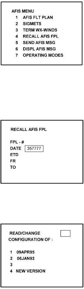
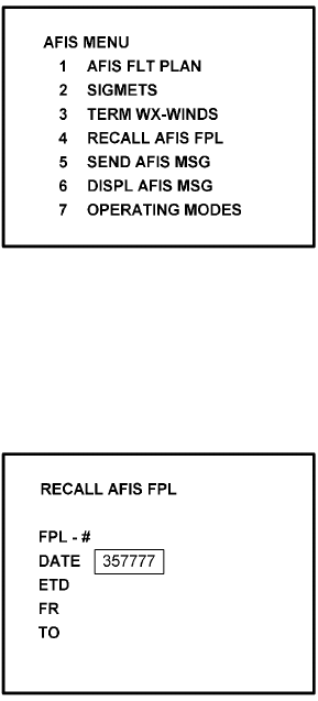
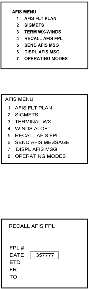
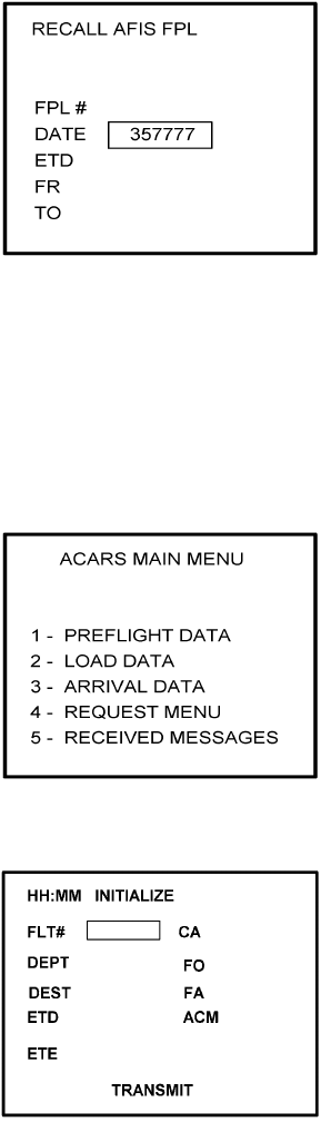
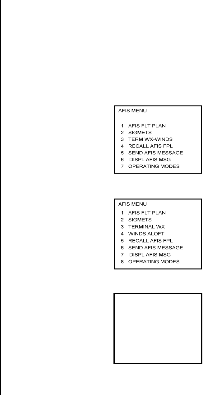
3. Press the DATA Key to display the AFIS MENU Page. See Figure 4-1.
Figure 4-1
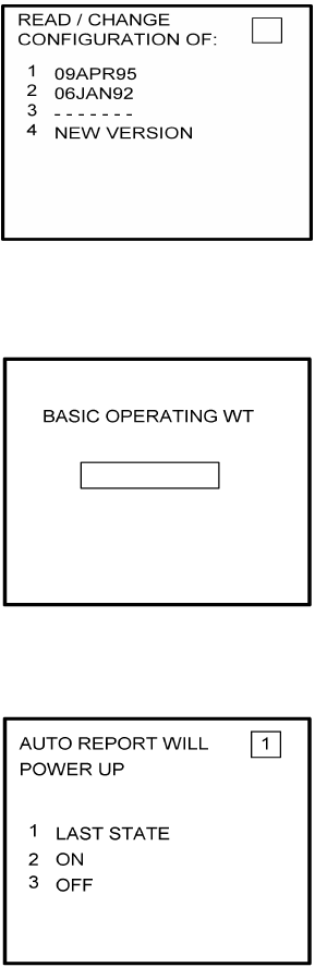
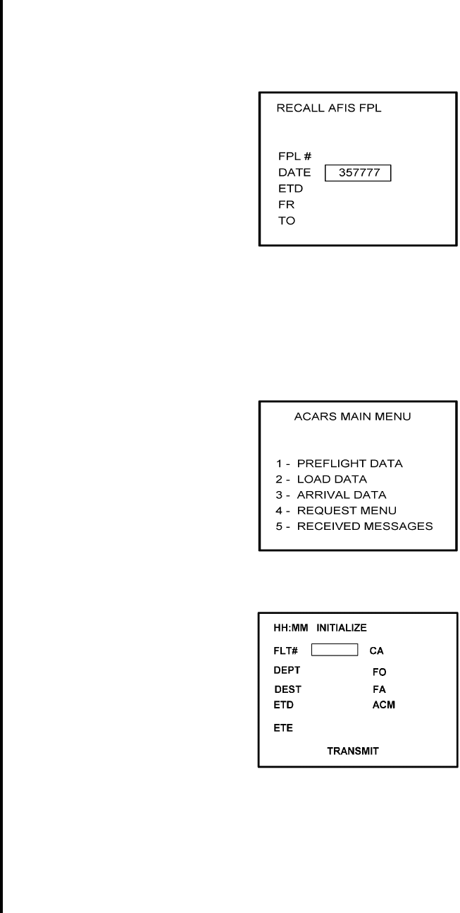
4. Use the UP or DOWN Arrow Key to position the cursor over Option 4, RECALL AFIS
FPL and press the ENTER Key. The RECALL AFIS FPL Page appears. Use the UP or
DOWN Arrow Key to position the cursor over the DATE field and enter 357777. Press
the ENTER Key. See Figure 4-2.
Figure 4-2
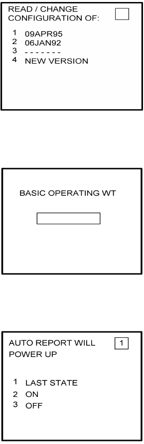
5. Select the AFIS configuration to be read or modified from the AFIS Configuration Menu
Page (Figure 4-3) and press the ENTER Key.
Figure 4-3
-------
Global
AIRBORNE FLIGHT INFORMATION SYSTEM
IMAFISJWA 4-5
March/2001
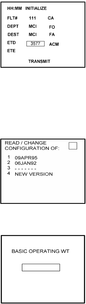
The dates of previously entered configurations are shown in Options 1 to 3. The
newest configuration date appears first. Option 4 allows for the entry of a new
configuration. Select Options 1 to 4 as desired and Figure 4-4 will be displayed.
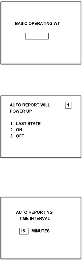
6. Insert the basic operating weight and press ENTER. See Figure 4-4.
Figure 4-4
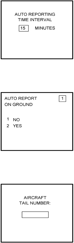
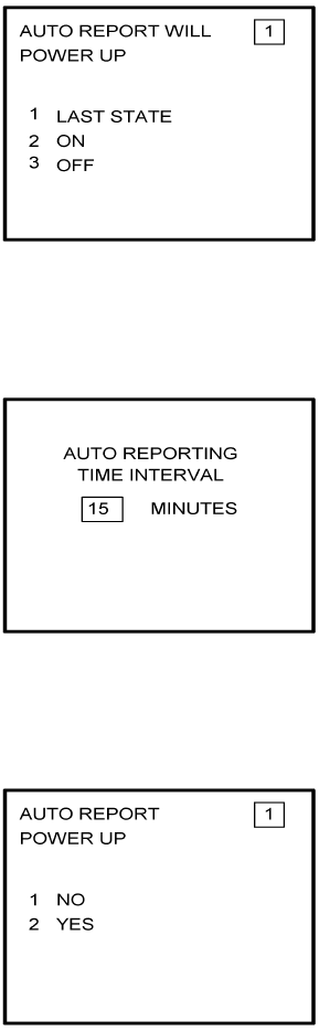
7. Insert the default for Auto Report and press ENTER. See Figure 4-5.
Figure 4-5
8. Insert 15 as the Auto Reporting time interval unless advised differently by the
pilot/operator and press ENTER. See Figure 4-6.
Figure 4-6
Global
AIRBORNE FLIGHT INFORMATION SYSTEM
IMAFISJWA 4-6
March/2001
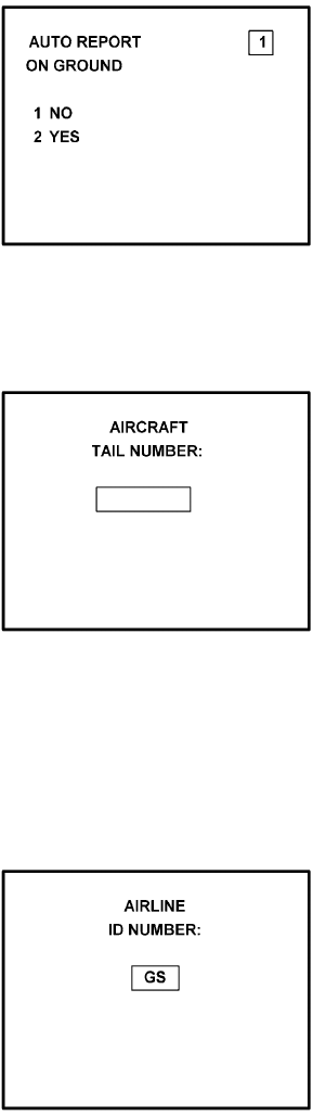
9. This step is applicable only to DMU P/N 42000-03-03 and 42000-04-03. Select Option
1 if reports are not wanted on the ground. Select Option 2 if reports on the ground are
required. See Figure 4-7.
Figure 4-7
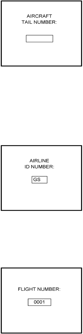
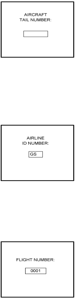
10. Insert complete aircraft registration number (tail number) in the cursor field and press
ENTER. See Figure 4-8.
Figure 4-8
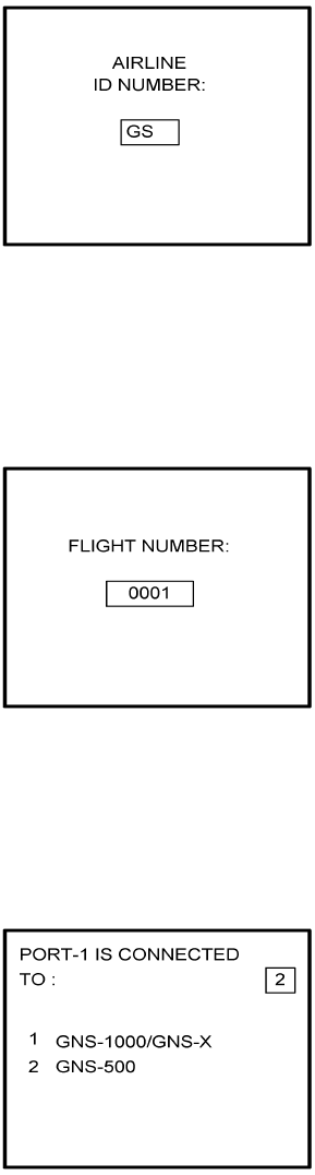
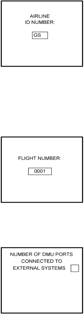
11. Insert GS as the Airline ID number and press ENTER. See Figure 4-9.
NOTE:
Currently, GS is the only valid entry and may change at a future time.
Figure 4-9
Global
AIRBORNE FLIGHT INFORMATION SYSTEM
IMAFISJWA 4-7
March/2001
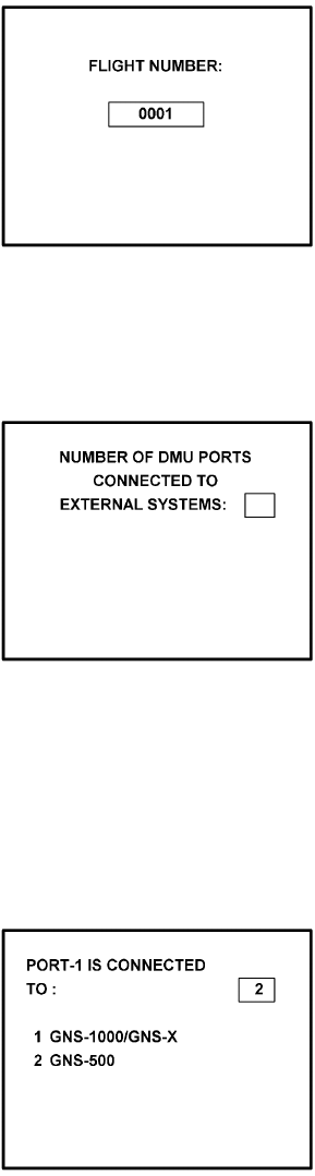
12. In the Flight Number cursor field, insert the number 0001 as shown in Figure 4-10.
Press ENTER.
NOTE:
Currently, 0001 is the only valid entry and may change at a future time.
Figure 4-10
13. This step is only applicable to DMU P/N 42000-01-01 and 42000-02-02. Determine the
number of NMUs connected to the DMU (there are a maximum of 3), insert the number
in the cursor field, and press ENTER. See Figure 4-11.
Figure 4-11
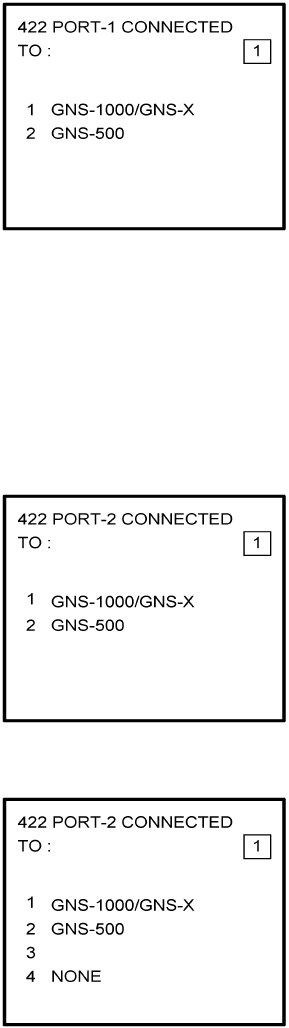
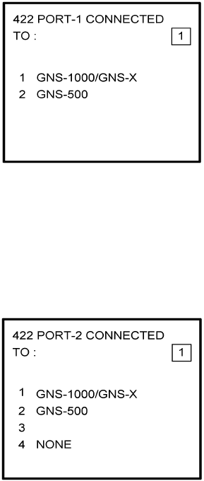
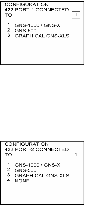
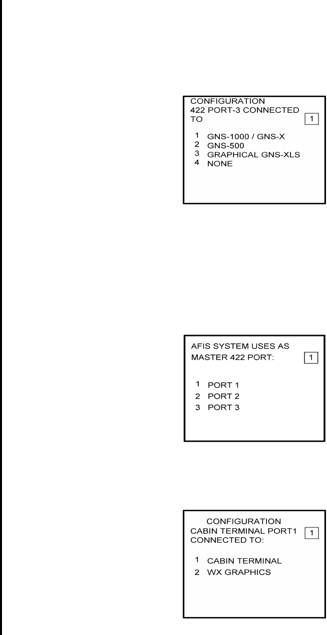
14. Complete this step for all other versions. Insert 2 as shown in Figure 4-12 to indicate
that Port 1 is connected to the GNS-500A system and press ENTER.
NOTE:
GNS-X applies also to GNS-XES, GNS-XL and GNS-XLS.
Figure 4-12
Global
AIRBORNE FLIGHT INFORMATION SYSTEM
IMAFISJWA 4-8
March/2001
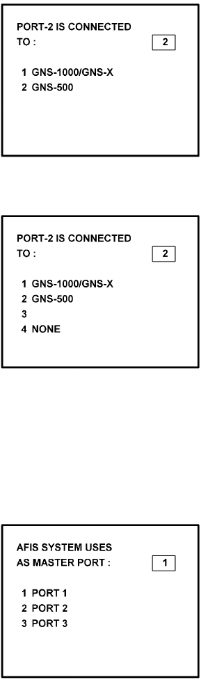
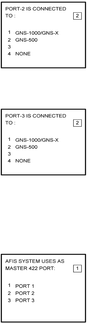
15. If applicable, insert 2 to designate that Port 2 is connected to the GNS-500A system.
Press ENTER. See Figure 4-13a for DMU P/N 42000-01-01 and 42000-02-02. See
Figure 4-13b for DMU P/N 42000-03-03 and 42000-04-03.
NOTE:
GNS-X applies also to GNS-XES, GNS-XL and GNS-XLS.
Figure 4-13A
Figure 4-13B
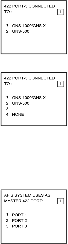
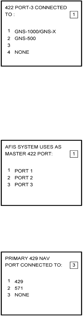
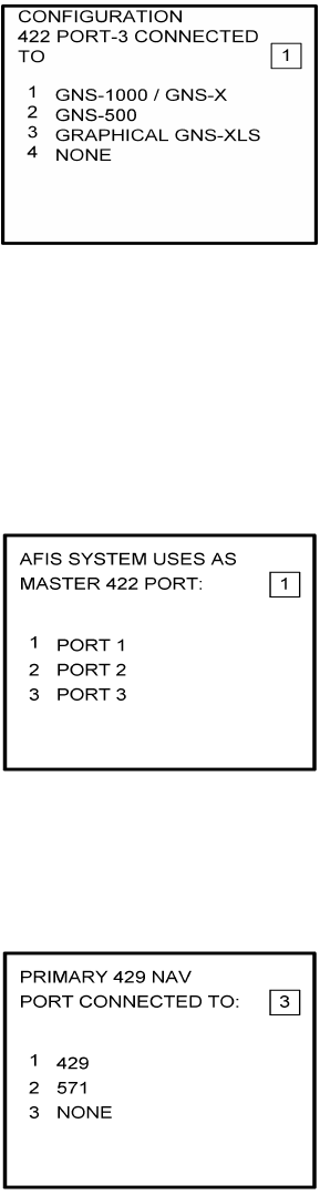
NOTE:
Program for Port 3 as necessary. Press ENTER to continue.
16. To designate Port 1 as the Master 422 Port, insert 1 and press ENTER. See Figure
4-14.
Figure 4-14
Global
AIRBORNE FLIGHT INFORMATION SYSTEM
IMAFISJWA 4-9
March/2001
NOTE
The master port refers to the use of one port by the software to have priority
over the data from other ports (i.e. CDU2). Global recommends use of Port
1.
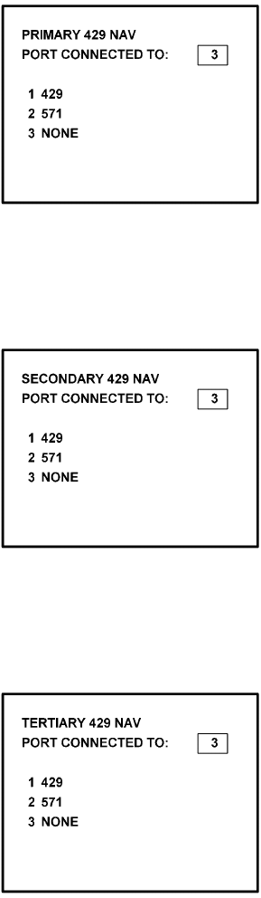
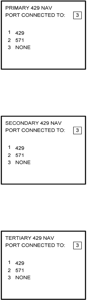
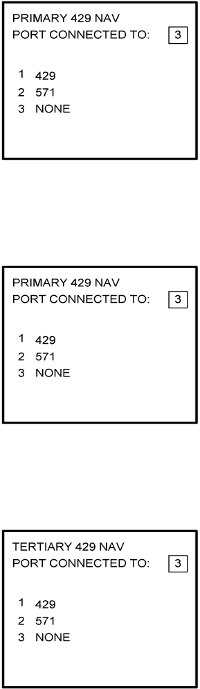
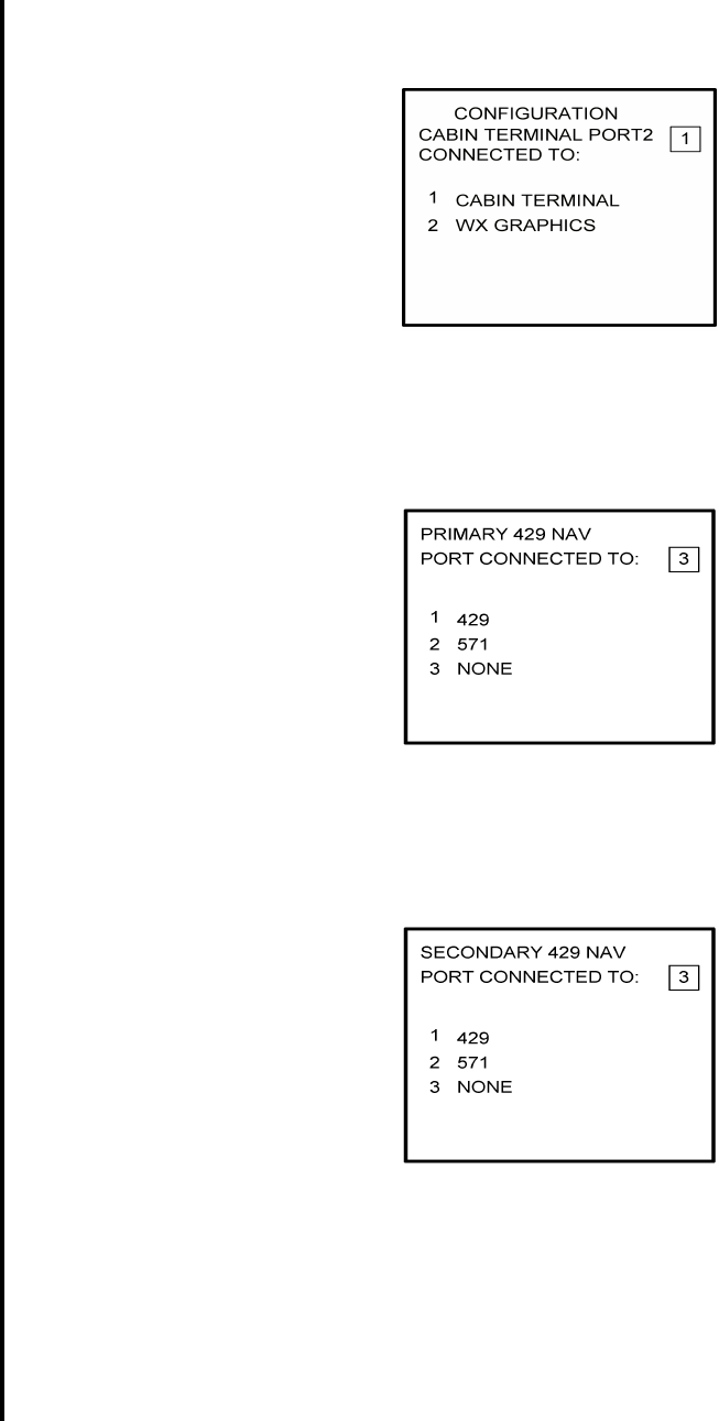
17. The 429 port option is not applicable to DMU P/N 42000-XX-XX. This page will only
appear if DMU P/N 42000-03-03 or 42000-04-03 is installed. If applicable, insert 3 and
press ENTER. See Figure 4-15.
Figure 4-15
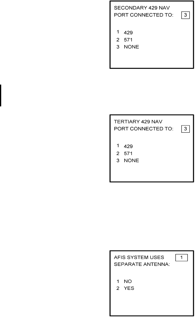
18. The 429 port option is not applicable to DMU P/N 42000-XX-XX. This page will only
appear if DMU P/N 42000-03-03 or 42000-04-03 is installed. If applicable, insert 3 and
press ENTER. See Figure 4-16.
Figure 4-16
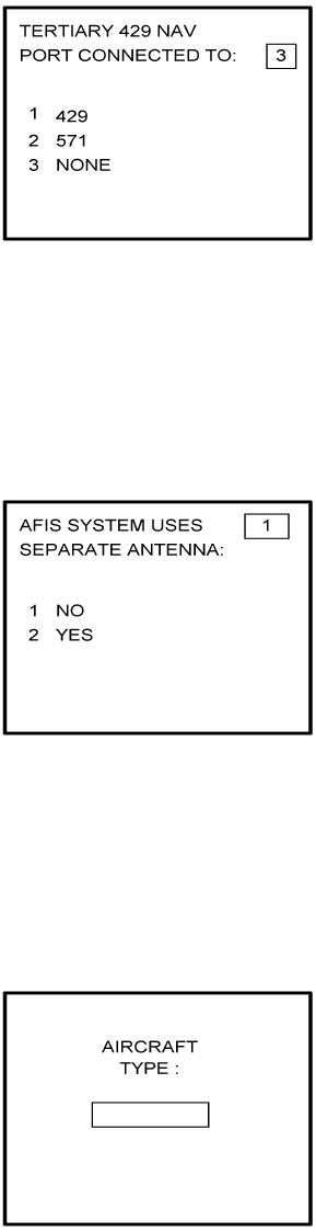
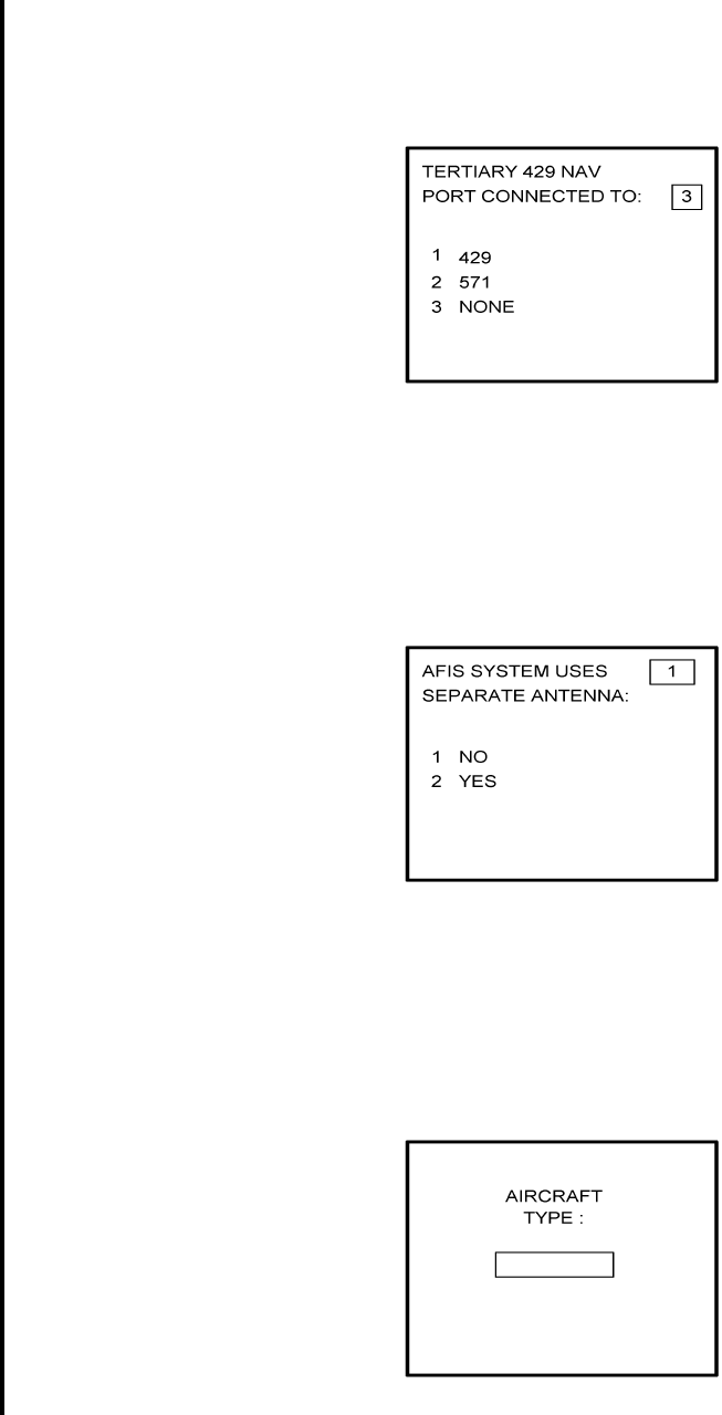
19. The 429 port option is not applicable to DMU P/N 42000-XX-XX. This page will only
appear if DMU P/N 42000-03-03 or 42000-04-03 is installed. If applicable, insert 3 and
press ENTER. See Figure 4-17.
Figure 4-17
Global
AIRBORNE FLIGHT INFORMATION SYSTEM
IMAFISJWA 4-10
March/2001
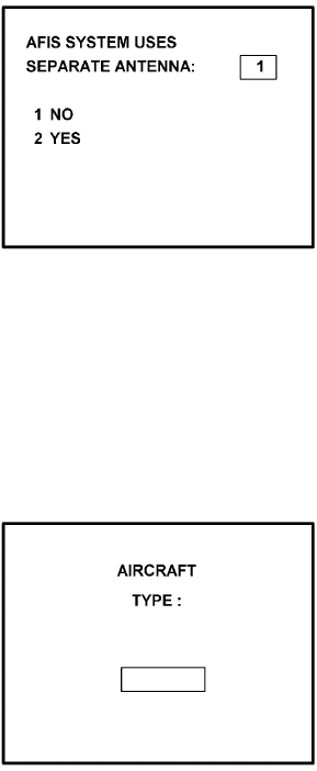
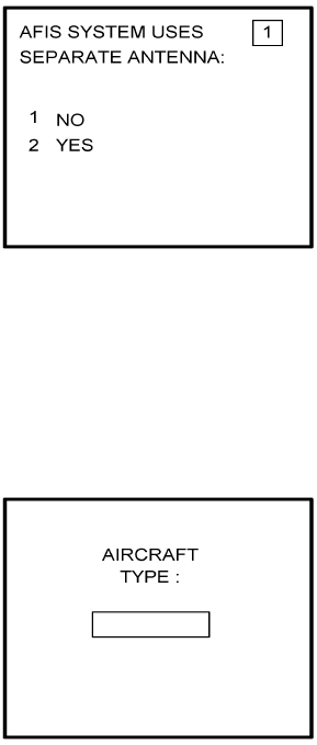
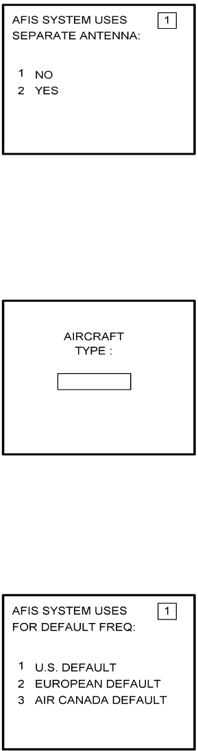
20. Select whether the AFIS system is using a separate antenna and press ENTER. See
Figure 4-18.
NOTE:
The Antenna Switching Unit (ASU) allows the AFIS system to share an
antenna with the VHF Com or use its own antenna.
Figure 4-18
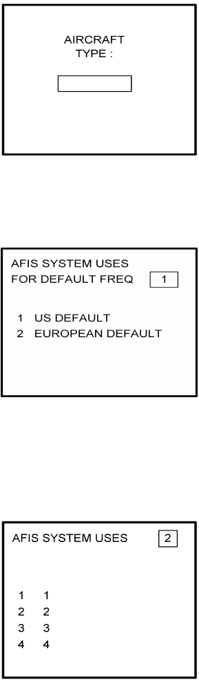
21. Insert type designator as listed in Table 4-1 and press ENTER. See Figure 4-19.
NOTE:
If the aircraft type is not listed in Table 4-1, contact Global Data Center to
obtain type designator.
Figure 4-19
Global
AIRBORNE FLIGHT INFORMATION SYSTEM
IMAFISJWA 4-11
March/2001
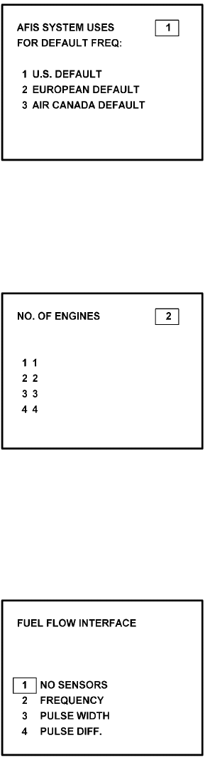
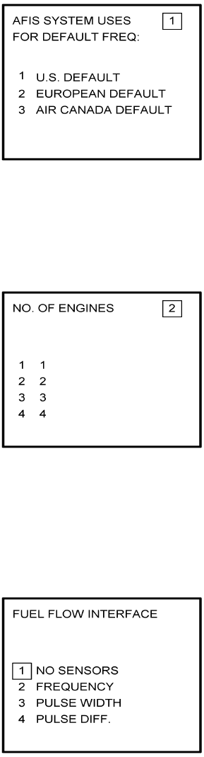
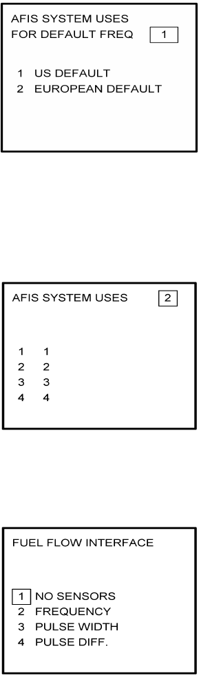
22. Select Option 1 for ARINC network, Option 2 for SITA or AVICOM network. Press
ENTER to continue. See Figure 4-20.
NOTE:
Air Canada network is no longer active.
Figure 4-20
23. Steps 23 and 24 are only applicable to Series 4/5 users with Fuel Flow option DMU
P/N 42000-02-02 or 42000-04-03. If other versions of the DMU are used, proceed to
Step 25. If applicable, select the number that corresponds to the number of engines on
the aircraft and press the ENTER Key. See Figure 4-21.
Figure 4-21
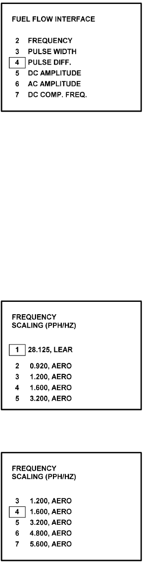
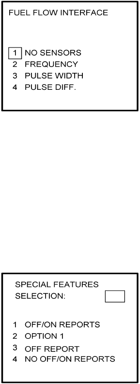
24. Fuel Flow Interface - Enter one of seven options. See Figure 4-22.
Using the Up and Down arrow keys, move the fuel flow sensor options into the
stationary cursor field. Scroll through and press the ENTER Key to select the desired
option.
Figure 4-22 (page 1)
Global
AIRBORNE FLIGHT INFORMATION SYSTEM
IMAFISJWA 4-12
March/2001
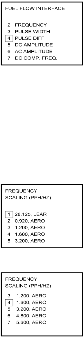
Figure 4-22 (PAGE 2)
(a) If Option 1 (NO SENSORS) is selected, the system will go to Step 25.
(b) If Option 2 (FREQUENCY) is selected, Figure 4-23 appears. Select the appropriate
manufacturer and scaling by using the Up and Down arrow keys to place the desired
option in the cursor field. Press ENTER.
NOTE:
See Section 1 to cross-reference the manufacturer part number to the fuel
flow type and frequency scaling. LEAR stands for J.E.T. fuel flow
manufacturer and AERO is AERO Systems.
Figure 4-23 (PAGE 1)
Figure 4-23 (PAGE 2)
Global
AIRBORNE FLIGHT INFORMATION SYSTEM
IMAFISJWA 4-13
March/2001
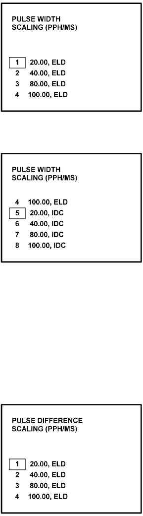
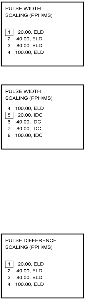
(c) If Option 3 (PULSE WIDTH) is selected, Figure 4-24 is displayed. Use the Up and
Down arrow keys to place the appropriate manufacturer/scaling in the cursor field.
Press ENTER.
NOTE:
See Section 1.3.2, SYSTEM SPECIFICATIONS, to cross-reference the
fuel flow indicator/transmitter manufacturer’s part number to the
appropriate scaling values. ELD stands for ELDEC. See Figure 4-24.
Figure 4-24 (PAGE 1)
Figure 4-24 (PAGE 2)
(d) If Option 4 (PULSE DIFF) is selected, Figure 4-25 is displayed. Use the Up and Down
arrow keys to place the appropriate manufacturer/scaling in the cursor field. Press
ENTER.
NOTE:
See Section 1.3.2, SYSTEM SPECIFICATIONS, to cross-reference the
fuel flow indicator/transmitter manufacturer’s part number to the
appropriate scaling values.
Figure 4-25
Global
AIRBORNE FLIGHT INFORMATION SYSTEM
IMAFISJWA 4-14
March/2001
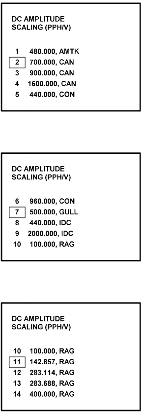
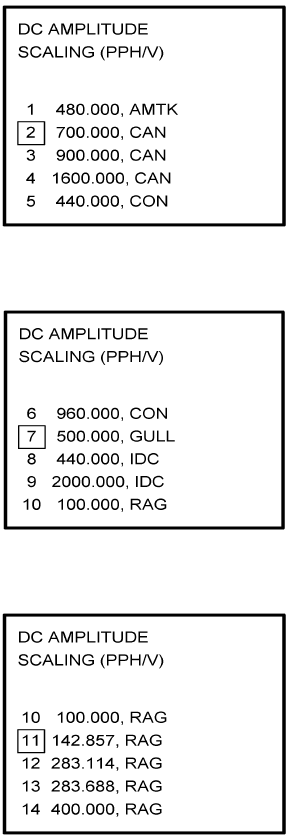
(e) If Option 5 (DC AMPLITUDE) is selected, Figure 4-26 is displayed. Use the Up and
Down arrow keys to place the appropriate manufacturer/scaling in the cursor field.
Press ENTER.
NOTE:
See Section 1.3.2, SYSTEM SPECIFICATIONS, to cross-reference the
fuel flow indicator/transmitter manufacturer’s part number to the
appropriate scaling values. AMTK stands for AMETEK. CAN is Canadian
Marconi, CON is Consolidated Airborne and RAG is Ragen Data System
Figure 4-26 (PAGE 1)
Figure 4-26 (PAGE 2)
Figure 4-26 (PAGE 3)
Global
AIRBORNE FLIGHT INFORMATION SYSTEM
IMAFISJWA 4-15
March/2001
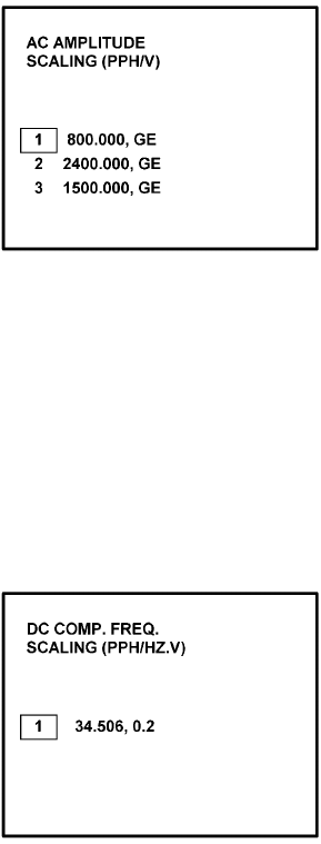
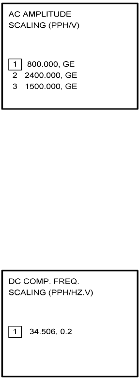
(f) If Option 6 (AC AMPLITUDE) is selected, Figure 4-27 is displayed. Use the Up and
Down arrow keys to place the appropriate manufacturer/scaling in the cursor field.
Press ENTER.
NOTE:
See Section 1.3.2, SYSTEM SPECIFICATIONS, to cross-reference the
fuel flow indicator/transmitter manufacturer’s part number to the
appropriate scaling values. GE stands for General Electric.
Figure 4-27
(g) If Option 7 (DC COMP. FREQ.) is selected, Figure 4-28 is displayed. Use the Up and
Down arrow keys to place the appropriate manufacturer/scaling in the cursor field.
Press ENTER.
NOTE:
See Section 1.3.2, SYSTEM SPECIFICATIONS, to cross-reference the
fuel flow indicator/transmitter manufacturer’s part number to the
appropriate scaling values.
Figure 4-28
Global
AIRBORNE FLIGHT INFORMATION SYSTEM
IMAFISJWA 4-16
March/2001
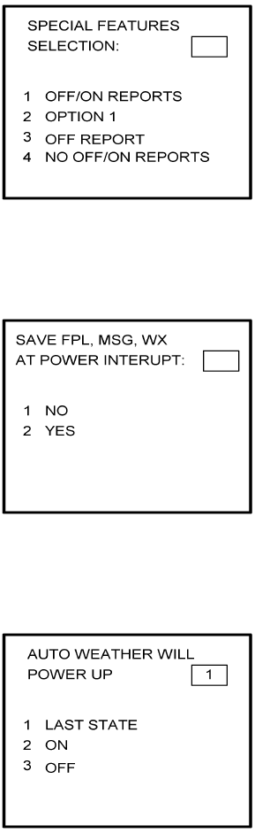
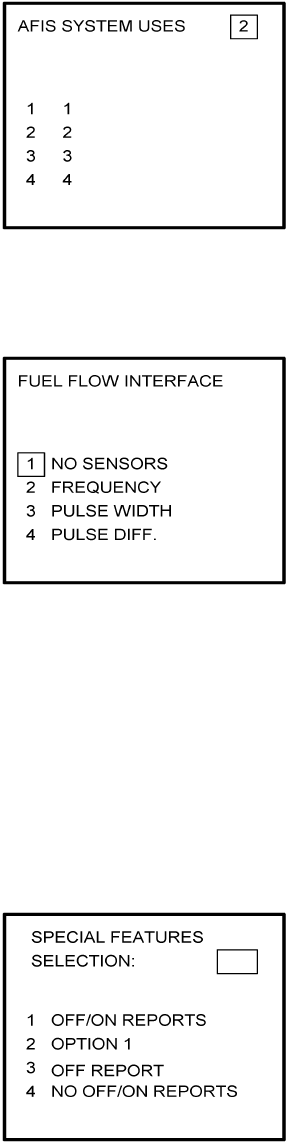
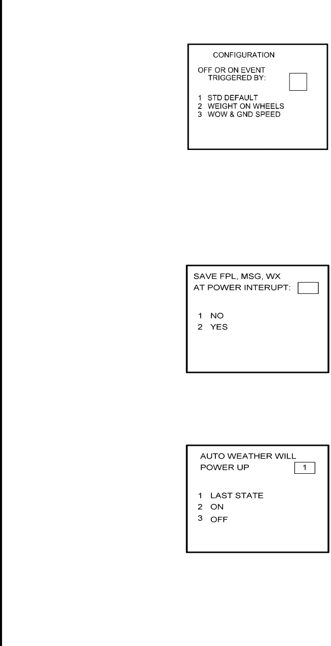
25. This step is only applicable to DMU P/N 42000-03-03 and 42000-04-03. If other
versions of DMU are used, proceed to Step 26.
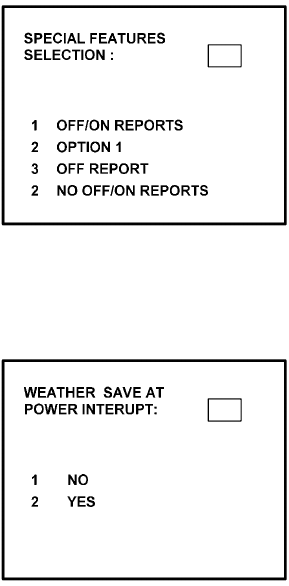
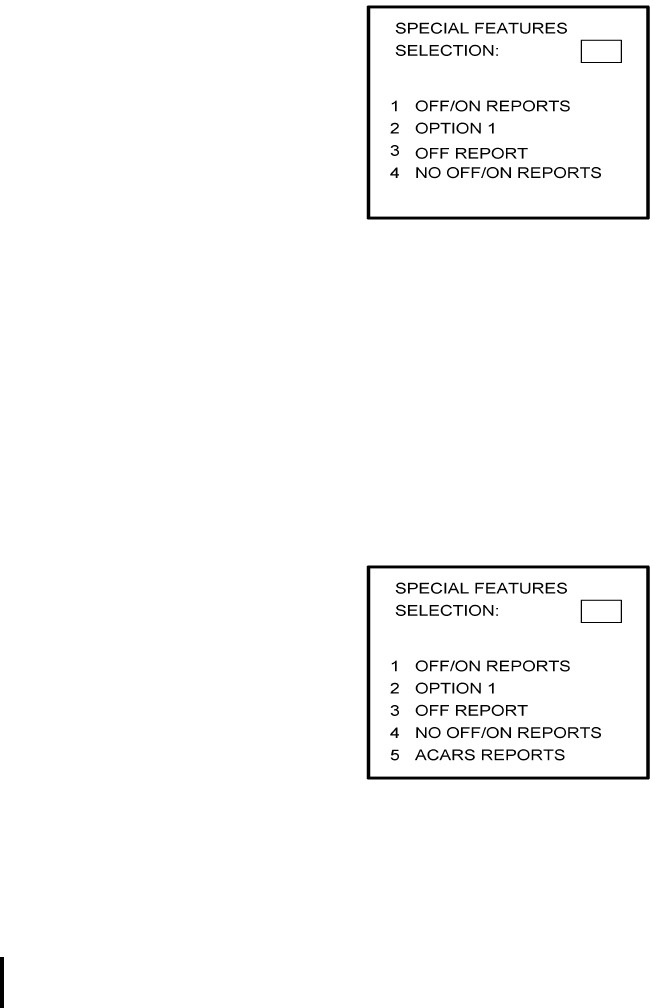
Select the applicable special feature option and press the ENTER Key to continue. See
Figure 4-29.
NOTE:
OFF/ON REPORTS = logging takeoff and landing times. OPTION 1 =
customer defined non-standard AFIS features. OFF REPORT = logging
takeoff times. NO OFF/ON REPORTS = no logging of takeoff and landing
times.
Figure 4-29
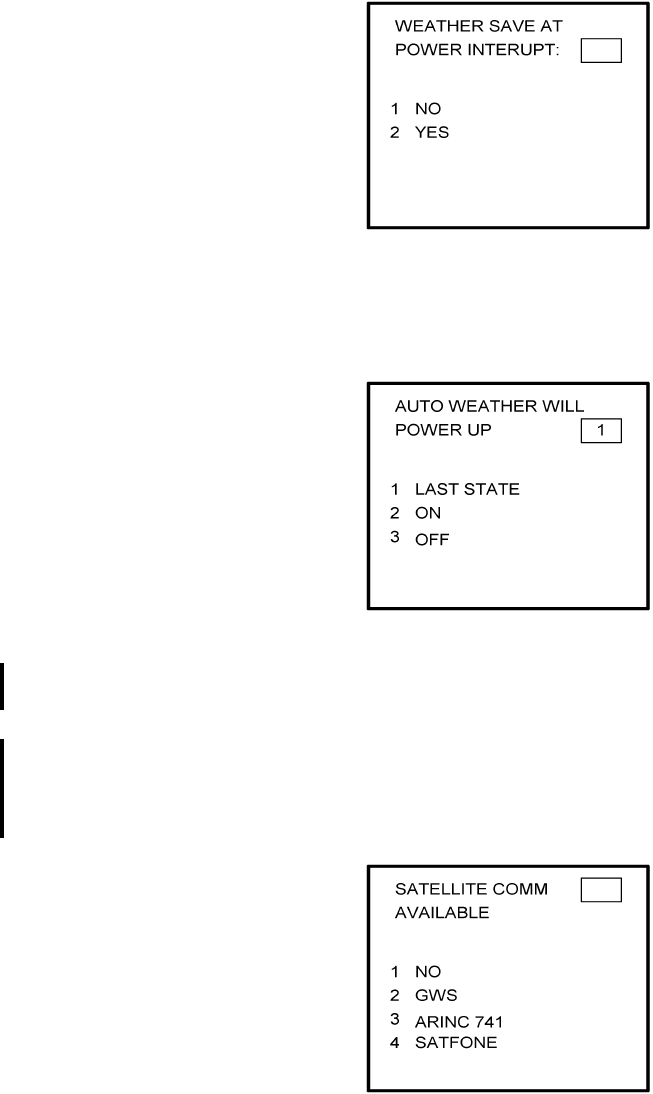
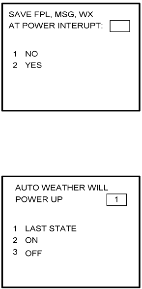
26. Select whether stored weather will be retained in memory when power is interrupted.
Press the ENTER Key to continue. See Figure 4-30.
Figure 4-30
Global
AIRBORNE FLIGHT INFORMATION SYSTEM
IMAFISJWA 4-17
March/2001
27. This step is only applicable to DMU P/N 42000-03-03 and 42000-04-03. If other
versions of the DMU are used, proceed to Step 30.
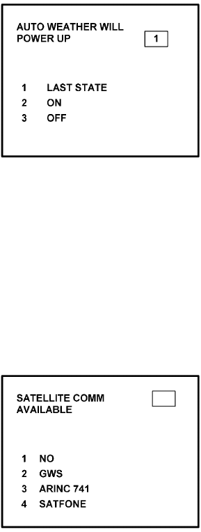
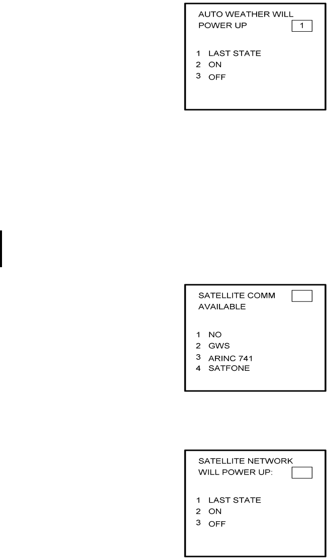
Select the desired option for Auto Weather update status at power up and press the
ENTER Key. See Figure 4-31.
Figure 4-31
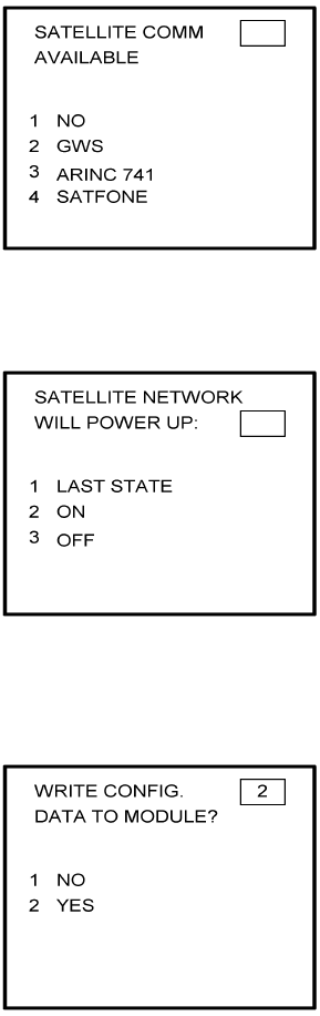
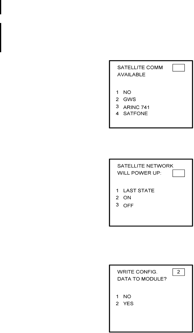
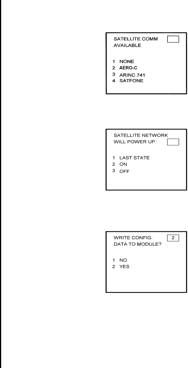
28. This step is only applicable to Series 4/5 users with Satellite Data Communication
System option DMU P/N 42000-03-03 and 42000-04-03. If other versions of the DMU
are used, proceed to Step 30.
If applicable, select Satcom Option 2 and press the ENTER Key. See Figure 4-32.
If Option 1 is selected, proceed to Step 30. Option 3 (ARINC 741) and Option 4
(SATFONE) are not available for DMU P/N 42000-03-03 and 42000-04-03. These
options apply to other FMS/DMU configurations discussed elsewhere.
Figure 4-32
Global
AIRBORNE FLIGHT INFORMATION SYSTEM
IMAFISJWA 4-18
March/2001
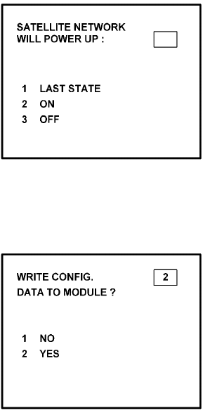
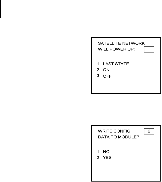
29. This step is only applicable to Series 4/5 users with Satellite Data Communication
System option DMU P/N 42000-03-03 and 42000-04-03. Also, Option 2 must have
been selected in Step 28. If other versions of the DMU are used or Option 1 was
selected in the previous step, proceed to Step 30. Select the desired option and press
the ENTER Key. See Figure 4-33.
Figure 4-33
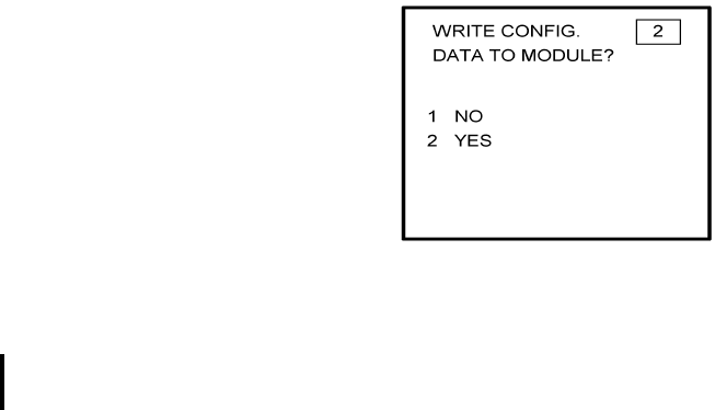
30. Write configuration data to the Configuration Module by selecting 2 and press the
ENTER Key. See Figure 4-34.
Figure 4-34
Global
AIRBORNE FLIGHT INFORMATION SYSTEM
IMAFISJWA 4-19
March/2001
4.2 CONFIGURATION MODULE PROGRAMMING FOR GNS-500A SERIES 4/5 WITH DMU
P/N 400-045500-XXXX.
NOTE:
The following configuration pages are not available for DMU P/N
400-045500-0210 or 400-045500-2010.
1. Install test connector P/N 12870-1 to the front of the DMU on J102.
2. Turn system on. Press the ENTER Key to accept DATE, GMT, and Position.
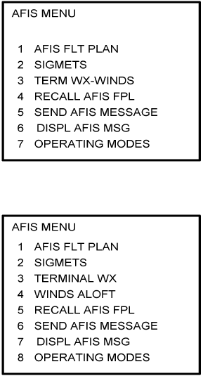
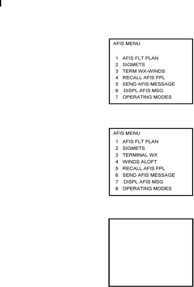
3. Press the DATA Key to display the AFIS MENU Page. See Figure 4-35.
Figure 4-35
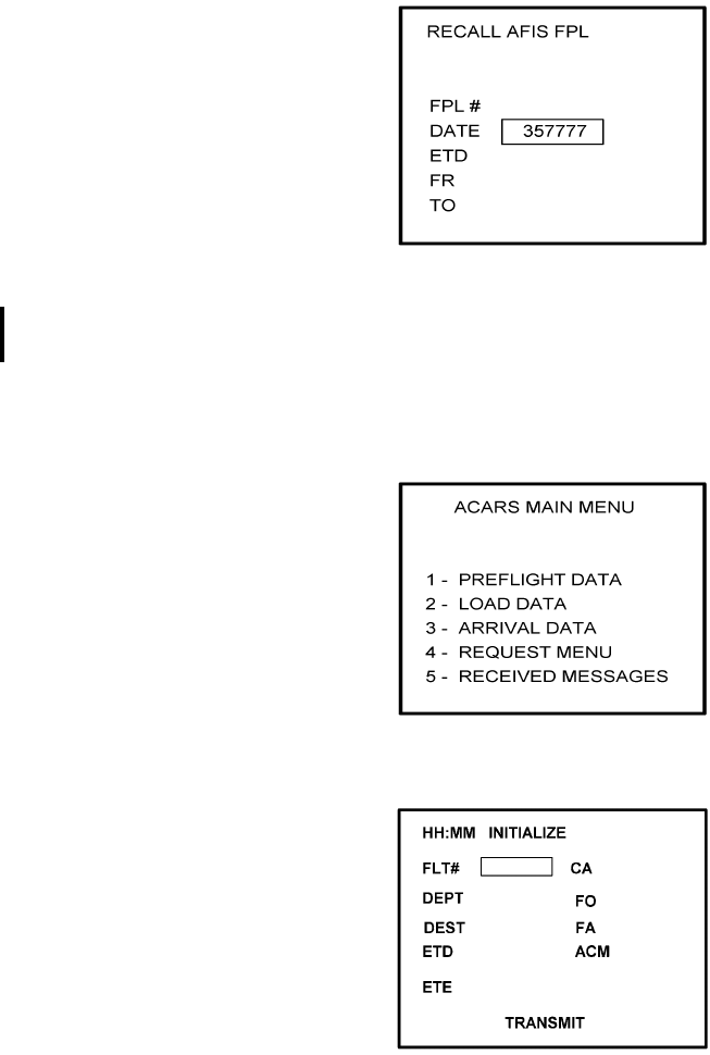
4. Use the UP or DOWN Arrow Key to position the cursor over Option 4, RECALL AFIS
FPL and press the ENTER Key. The RECALL AFIS FPL Page appears. Use the UP or
DOWN Arrow Key to position the cursor over the DATE field and enter 357777. Press
the ENTER Key. See Figure 4-36.
Figure 4-36
Global
AIRBORNE FLIGHT INFORMATION SYSTEM
IMAFISJWA 4-20
March/2001
5. Select the AFIS configuration to be read or modified from the AFIS Configuration Menu
Page (Figure 4-37) and press the ENTER Key.
The dates of previously entered configurations are shown in Options 1 to 3. The
newest configuration date appears first. Option 4 allows for the entry of a new
configuration. Select Options 1 to 4 as desired and Figure 4-38 will be displayed.
Figure 4-37
6. Insert the basic operating weight and press ENTER. See Figure 4-38.
Figure 4-38
7. Insert the default for Auto Report and press ENTER. See Figure 4-39.
Figure 4-39

Global
AIRBORNE FLIGHT INFORMATION SYSTEM
IMAFISJWA 4-21
March/2001
8. Insert 15 as the Auto Reporting time interval unless advised differently by the
pilot/operator and press ENTER. See Figure 4-40.
Figure 4-40
9. Select Option 1 if reports are not wanted on the ground. Select Option 2 if reports on
the ground are required. See Figure 4-41.
Figure 4-41
10. Insert complete aircraft registration number (tail number) in the cursor field and press
ENTER. See Figure 4-42.
Figure 4-42
Global
AIRBORNE FLIGHT INFORMATION SYSTEM
IMAFISJWA 4-22
March/2001
11. Insert GS as the Airline ID number and press ENTER. See Figure 4-43.
NOTE:
Currently, GS is the only valid entry and may change at a future time.
Figure 4-43
12. In the Flight Number cursor field, insert the number 0001 as shown in Figure 4-44.
Press ENTER.
NOTE:
Currently, 0001 is the only valid entry and may change at a future time.
Figure 4-44
13. Insert 2 as shown in Figure 4-45 to indicate that Port 1 is connected to the GNS-500A
system and press ENTER.
NOTE:
GNS-X applies also to GNS-XES, GNS-XL and GNS-XLS.
Figure 4-45
Global
AIRBORNE FLIGHT INFORMATION SYSTEM
IMAFISJWA 4-23
March/2001
14. If applicable, insert 2 to designate that Port 2 is connected to the GNS-500A system.
Press ENTER. See Figure 4-46.
NOTE:
GNS-X applies also to GNS-XES, GNS-XL and GNS-XLS.
Figure 4-46
15. If applicable, insert 2 to designate that Port 3 of connected to the GNS-500A system
and press ENTER. See Figure 4-47.
Figure 4-47
16. To designate Port 1 as the Master 422 Port, insert 1 and press ENTER. See Figure
4-48.
NOTE:
The master port refers to the use of one port by the software to have
priority over the data from other ports (i.e. CDU2). Honeywell
recommends use of Port 1.
Figure 4-48
Global
AIRBORNE FLIGHT INFORMATION SYSTEM
IMAFISJWA 4-24
March/2001
17. The 429 port option is only applicable when other manufacturer’s navigation systems
are installed. If only GWS systems are used, insert 3 and press ENTER. See Figure
4-49.
Figure 4-49
18. The 429 port option is only applicable when other manufacturer’s navigation systems
are installed. If only Global systems are used, insert 3 and press ENTER. See Figure
4-50.
Figure 4-50
19. The 429 port option is only applicable when other manufacturer’s navigation systems
are installed. If only GWS systems are used, insert 3 and press ENTER. See Figure
4-51.
Figure 4-51
Global
AIRBORNE FLIGHT INFORMATION SYSTEM
IMAFISJWA 4-25
March/2001
20. Select whether the AFIS system is using a separate antenna and press ENTER. See
Figure 4-52.
NOTE:
The Antenna Switching Unit (ASU) allows the AFIS system to share an
antenna with the VHF Comm or use its own antenna.
Figure 4-52
21. Insert type designator as listed in Table 4-1 and press ENTER. See Figure 4-53.
NOTE:
If the aircraft type is not listed in Table 4-1, contact Global Data
Center to obtain type designator.
Figure 4-53
Global
AIRBORNE FLIGHT INFORMATION SYSTEM
IMAFISJWA 4-26
March/2001
22. Select Option 1 for ARINC network, Option 2 for SITA or AVICOM network. Press
ENTER to continue. See Figure 4-54.
NOTE:
Air Canada network is no longer active.
Figure 4-54
23. Steps 23 and 24 are only applicable to Series 4/5 users with Fuel Flow option DMU
P/N 400-045500-0002, 400-045500-0004 or 400-045500-0006. If other versions of the
DMU are used, proceed to Step 25. If applicable, select the number that corresponds
to the number of engines on the aircraft and press the ENTER Key. See Figure 4-55.
Figure 4-55
24. Fuel Flow Interface - Enter one of seven options. See Figure 4-56.
Using the Up and Down arrow keys, move the fuel flow sensor options into the
stationary cursor field. Scroll through and press the ENTER Key to select the desired
option.
Figure 4-56 (PAGE 1)
Global
AIRBORNE FLIGHT INFORMATION SYSTEM
IMAFISJWA 4-27
March/2001
Figure 4-56 (PAGE 2)
(a) If Option 1 (NO SENSORS) is selected, the system will go to Step 25.
(b) If Option 2 (FREQUENCY) is selected, Figure 4-57 appears. Select the appropriate
manufacturer and scaling by using the Up and Down arrow keys to place the desired
option in the cursor field. Press ENTER.
NOTE:
See Section 1.3.2, SYSTEM SPECIFICATIONS, to cross-reference the
manufacturer part number to the fuel flow type and frequency scaling.
LEAR stands for J.E.T. fuel flow manufacturer and AERO is AERO
Systems.
Figure 4-57 (PAGE 1)
Figure 4-57 (PAGE 2)
Global
AIRBORNE FLIGHT INFORMATION SYSTEM
IMAFISJWA 4-28
March/2001
(c) If Option 3 (PULSE WIDTH) is selected, Figure 4-58 is displayed. Use the Up and
Down arrow keys to place the appropriate manufacturer/scaling in the cursor field.
Press ENTER.
NOTE:
See Section 1.3.2, SYSTEM SPECIFICATIONS, to cross-reference the
fuel flow indicator/transmitter manufacturer’s part number to the
appropriate scaling values. ELD stands for ELDEC. See Figure 4-58.
Figure 4-58 (PAGE 1)
Figure 4-58 (PAGE 2)
(d) If Option 4 (PULSE DIFF) is selected, Figure 4-59 is displayed. Use the Up and Down
arrow keys to place the appropriate manufacturer/scaling in the cursor field. Press
ENTER.
NOTE:
See Section 1.3.2, SYSTEM SPECIFICATIONS, to cross-reference the
fuel flow indicator/transmitter manufacturer’s part number to the
appropriate scaling values.
Figure 4-59
Global
AIRBORNE FLIGHT INFORMATION SYSTEM
IMAFISJWA 4-29
March/2001
(e) If Option 5 (DC AMPLITUDE) is selected, Figure 4-60 is displayed. Use the Up and
Down arrow keys to place the appropriate manufacturer/scaling in the cursor field.
Press ENTER.
NOTE:
See Section 1.3.2, SYSTEM SPECIFICATIONS, to cross-reference the
fuel flow indicator/transmitter manufacturer’s part number to the
appropriate scaling values. AMTK stands for AMETEK. CAN is Canadian
Marconi, CON is Consolidated Airborne and RAG is Ragen Data System.
Figure 4-60 (PAGE 1)
Figure 4-60 (PAGE 2)
Figure 4-60 (PAGE 3)
Global
AIRBORNE FLIGHT INFORMATION SYSTEM
IMAFISJWA 4-30
March/2001
(f) If Option 6 (AC AMPLITUDE) is selected, Figure 4-61 is displayed. Use the Up and
Down arrow keys to place the appropriate manufacturer/scaling in the cursor field.
Press ENTER.
NOTE:
See Section 1.3.2, SYSTEM SPECIFICATIONS, to cross-reference the
fuel flow indicator/transmitter manufacturer’s part number to the
appropriate scaling values. GE stands for General Electric.
Figure 4-61
(g) If Option 7 (DC COMP. FREQ.) is selected, Figure 4-62 is displayed. Use the Up and
Down arrow keys to place the appropriate manufacturer/scaling in the cursor field.
Press ENTER.
NOTE:
See Section 1.3.2, SYSTEM SPECIFICATIONS, to cross-reference the
fuel flow indicator/transmitter manufacturer’s part number to the
appropriate scaling values.
Figure 4-62
Global
AIRBORNE FLIGHT INFORMATION SYSTEM
IMAFISJWA 4-31
March/2001
25. Select the applicable special feature option and press the ENTER Key to continue.
See Figure 4-63.
NOTE:
OFF/ON REPORTS = logging takeoff and landing times. OPTION 1 =
customer defined non-standard AFIS features. OFF REPORT = logging
takeoff times. NO OFF/ON REPORTS = no logging of takeoff and landing
times.
Figure 4-63
26. Select whether stored flight plans, messages and weather will be retained in memory
when power is interrupted. Press the ENTER Key to continue. See Figure 4-64.
Figure 4-64
27. Select the desired option for Auto Weather update status at power up and press the
ENTER Key. See Figure 4-65.
Figure 4-65
Global
AIRBORNE FLIGHT INFORMATION SYSTEM
IMAFISJWA 4-32
March/2001
28. This step is only applicable to Series 4/5 users with Satellite Data Communication
System option DMU P/N 400-045500-0003, 400-045500-0004, 400-045500-0005 or
400-045500-0006. If other versions of the DMU are used, proceed to Step 30.
If applicable, select Satcom Option 2 and press the ENTER Key. See Figure 4-66.
If Option 1 is selected, proceed to Step 30. Options 3 and 4 are only available with
DMU P/N 400-045500-0005 or 400-045500-0006.
Figure 4-66
29. Select the desired option and press the ENTER Key. See Figure 4-67.
Figure 4-67
30. Write configuration data to the Configuration Module by selecting 2 and press the
ENTER Key. See Figure 4-68.
Figure 4-68
Global
AIRBORNE FLIGHT INFORMATION SYSTEM
IMAFISJWA 4-33
March/2001
4.3 CONFIGURATION MODULE PROGRAMMING FOR GNS-1000, GNS-X, GNS-XES,
GNS-XL OR GNS-XLS WITH DMU P/N 42000-01-01 OR 42000-03-03
1. Install test connector P/N 12870-1 to the front of the DMU on J102.
2. Turn system on. Press the ENTER Key to accept DATE, GMT, and Position.
3. Press the PLAN Key or AFIS Key to display the AFIS MENU Page. See Figure 4-69 or
Figure 4-70.
Figure 4-69
Figure 4-70
4. Use the UP or DOWN Arrow Key to position the cursor over the RECALL AFIS FPL
option and press the ENTER Key. The RECALL AFIS FPL Page appears. Use the UP
or DOWN Arrow Key to position the cursor over the DATE field and enter 357777.
Press the ENTER Key. See Figure 4-71.
Figure 4-71
Global
AIRBORNE FLIGHT INFORMATION SYSTEM
IMAFISJWA 4-34
March/2001
5. Select the AFIS configuration to be read or modified from the AFIS Configuration Menu
Page (Figure 4-69) and press the ENTER Key.
The dates of previously entered configurations are shown in Options 1 to 3. The
newest configuration date appears first. Option 4 allows for the entry of a new
configuration. Select Options 1 to 4 as desired and Figure 4-72 will be displayed.
Figure 4-72
6. Insert the basic operating weight and press ENTER. See Figure 4-73.
Figure 4-73
7. Insert the default for Auto Report and press ENTER. See Figure 4-74.
Figure 4-74
Global
AIRBORNE FLIGHT INFORMATION SYSTEM
IMAFISJWA 4-35
March/2001
8. Insert 15 as the Auto Reporting time interval unless advised differently by the
pilot/operator and press ENTER. See Figure 4-75.
Figure 4-75
9. Select Option 1 if reports are not wanted on the ground. Select Option 2 if reports on
the ground are required. See Figure 4-76.
Figure 4-76
10. Insert complete aircraft registration number (tail number) in the cursor field and press
ENTER. See Figure 4-77.
Figure 4-77
Global
AIRBORNE FLIGHT INFORMATION SYSTEM
IMAFISJWA 4-36
March/2001
11. Insert GS as the Airline ID number and press ENTER. See Figure 4-78.
NOTE:
Currently, GS is the only valid entry and may change at a future time.
Figure 4-78
12. In the Flight Number cursor field, insert the number 0001 as shown in Figure 4-79.
Press ENTER.
NOTE:
Currently, 0001 is the only valid entry and may change at a future time.
Figure 4-79
13. This step is only applicable to DMU P/N 42000-01-01. Determine the number of CDUs
or NMUs connected to the DMU (there are a maximum of 3), insert the number in the
cursor field, and press ENTER. See Figure 4-80.
Figure 4-80
Global
AIRBORNE FLIGHT INFORMATION SYSTEM
IMAFISJWA 4-37
March/2001
14. Insert 1 as shown in Figure 4-81 to indicate that Port 1 is connected to the GNS-1000
or GNS-X system and press ENTER.
NOTE:
GNS-X applies also to GNS-XES, GNS-XL and GNS-XLS.
Figure 4-81
15. If applicable, insert 1 to designate that Port 2 is connected to the GNS-1000 or GNS-X
system. Press ENTER. See Figure 4-82a for DMU P/N 42000-01-01. See Figure 4-82b
for DMU P/N 42000-03-03.
NOTE:
GNS-X applies also to GNS-XES, GNS-XL and GNS-XLS.
Figure 4-82A
Figure 4-82B
Global
AIRBORNE FLIGHT INFORMATION SYSTEM
IMAFISJWA 4-38
March/2001
16. If applicable, insert 1 to designate that Port 3 is connected to the GNS-1000 or GNS-X
system. Press ENTER. See Figure 4-83a for DMU P/N 42000-01-01. See Figure 4-83b
for DMU P/N 42000-03-03.
NOTE:
GNS-X applies also to GNS-XES, GNS-XL and GNS-XLS.
Figure 4-83A
Figure 4-83B
17. To designate Port 1 as the Master 422 Port, insert 1 and press ENTER. See Figure
4-84.
NOTE:
The master port refers to the use of one port by the software to have priority
over the data from other ports (ie CDU2). Global recommends use of Port 1.
Figure 4-84
Global
AIRBORNE FLIGHT INFORMATION SYSTEM
IMAFISJWA 4-39
March/2001
18. The 429 port option is not applicable to DMU P/N 42000-XX-XX. This page will only
appear if DMU P/N 42000-03-03 is installed. If applicable, insert 3 and press ENTER.
See Figure 4-85.
Figure 4-85
19. The 429 port option is not applicable to DMU P/N 42000-XX-XX. This page will only
appear if DMU P/N 42000-03-03 is installed. If applicable, insert 3 and press ENTER.
See Figure 4-86.
Figure 4-86
20. The 429 port option is not applicable to DMU P/N 42000-XX-XX. This page will only
appear if DMU P/N 42000-03-03 is installed. If applicable, insert 3 and press ENTER.
See Figure 4-87.
Figure 4-87
Global
AIRBORNE FLIGHT INFORMATION SYSTEM
IMAFISJWA 4-40
March/2001
21. Select whether the AFIS system is using a separate antenna and press ENTER. See
Figure 4-88.
NOTE:
The Antenna Switching Unit (ASU) allows the AFIS system to share an
antenna with the VHF Comm or use its own antenna.
Figure 4-88
22. Insert type designator as listed in Table 4-1 and press ENTER. See Figure 4-89.
NOTE:
If the aircraft type is not listed in Table 4-1, contact Global Data Center to
obtain type designator.
Figure 4-89
23. Select Option 1 for ARINC network, Option 2 for SITA or AVICOM network, or Option
3 for Air Canada network. Press ENTER to continue. See Figure 4-90.
NOTE:
Air Canada network is no longer active.
Figure 4-90
Global
AIRBORNE FLIGHT INFORMATION SYSTEM
IMAFISJWA 4-41
March/2001
24. Fuel Flow option is not available for GNS-1000, GNS-X, GNS-XES, GNS-XL or
GNS-XLS. Insert 1 and press the ENTER Key. See Figure 4-91.
Figure 4-91
25. Fuel Flow option is not available for GNS-1000, GNS-X, GNS-XES, GNS-XL or
GNS-XLS. Select 1 and press the ENTER Key. See Figure 4-92.
Figure 4-92
26. This step is only applicable to DMU P/N 42000-03-03. If other versions of DMU are
used, proceed to Step 27. Select the applicable special feature option and press the
ENTER Key to continue. See Figure 4-93.
NOTE:
OFF/ON REPORTS = logging takeoff and landing times. OPTION 1 =
customer defined non-standard AFIS features. OFF REPORT = logging
takeoff times. NO OFF/ON REPORTS = no logging of takeoff and landing
times.
Figure 4-93
Global
AIRBORNE FLIGHT INFORMATION SYSTEM
IMAFISJWA 4-42
March/2001
27. Select whether stored weather will be retained in memory when power is interrupted.
Press the ENTER Key to continue. See Figure 4-94.
Figure 4-94
28. This step is only applicable to DMU P/N 42000-03-03. If other versions of the DMU are
used, proceed to Step 30. Select the desired option for Auto Weather update status at
power up and press the ENTER Key. See Figure 4-95.
Figure 4-95
29. This step is only applicable to GNS-1000, GNS-X, GNS-XES, GNS-XL or GNS-XLS with
Satellite Data Communication System option DMU P/N 42000-03-03.
If applicable, select Satcom Option 2 and press the ENTER Key. See Figure 4-96. If
Option 1 is selected, proceed to Step 31. Option 3 (ARINC 741) and Option 4
(SATFONE) are not available for DMU P/N 42000-03-03. These options apply to other
FMS/DMU configurations discussed elsewhere.
Figure 4-96
Global
AIRBORNE FLIGHT INFORMATION SYSTEM
IMAFISJWA 4-43
March/2001
30. This step is only applicable to GNS-1000, GNS-X, GNS-XES, GNS-XL or GNS-XLS with
Satellite Data Communication System option DMU P/N 42000-03-03. If other versions
of the DMU are used, proceed to Step 31.
Select the desired option and press the ENTER Key. See Figure 4-97.
Figure 4-97
31. Write configuration data to the Configuration Module by selecting 2 and press the
ENTER Key. See Figure 4-98.
Figure 4-98
Global
AIRBORNE FLIGHT INFORMATION SYSTEM
IMAFISJWA 4-44
March/2001
4.4 CONFIGURATION MODULE PROGRAMMING FOR GNS-1000, GNS-X, GNS-XES,
GNS-XL OR GNS-XLS WITH DMU P/N 400-045500-0001, 400-045500-0003 OR
400-045500-0005 AND OTHER FMS MANUFACTURES USING DMU P/N
400-045500-0001, 0002, -0003, -0004, -0005, -0006 OR -0130
1. Install test connector P/N 12870-1 to the front of the DMU on J102.
2. Turn system on. Press the ENTER Key to accept DATE, GMT, and Position.
(a) If DMU has been configured for ACARS proceed to step 4(a) otherwise step 3.
3. Press the PLAN Key or AFIS Key to display the AFIS MENU Page. See Figure 4-99 or
Figure 4-100.
Figure 4-99
Figure 4-100
Global
AIRBORNE FLIGHT INFORMATION SYSTEM
IMAFISJWA 4-45
March/2001
4. Use the UP or DOWN Arrow Key or Line >Select keys to position the cursor over the
RECALL AFIS FPL option and press the ENTER Key. The RECALL AFIS FPL Page
appears. Use the UP or DOWN Arrow Key or Line Select keys to position the cursor
over the DATE field and enter 357777. Press the ENTER Key. See Figure 4-101.
Figure 4-101
NOTE:
ITEMS 4(a) through 4(k) are only available for -0003 or -0130. For other
part numbers skip to item 5.
(a) Press the PLAN key or AFIS key to display the ACARS page. See Figure 4-102 or
4-103.
Figure 4-102
Figure 4-103
Global
AIRBORNE FLIGHT INFORMATION SYSTEM
IMAFISJWA 4-46
March/2001
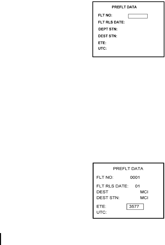
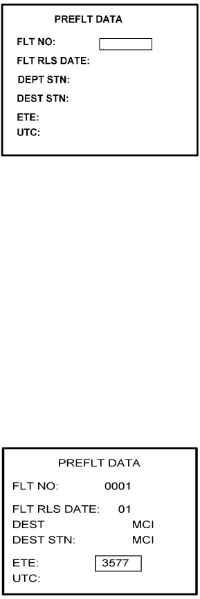
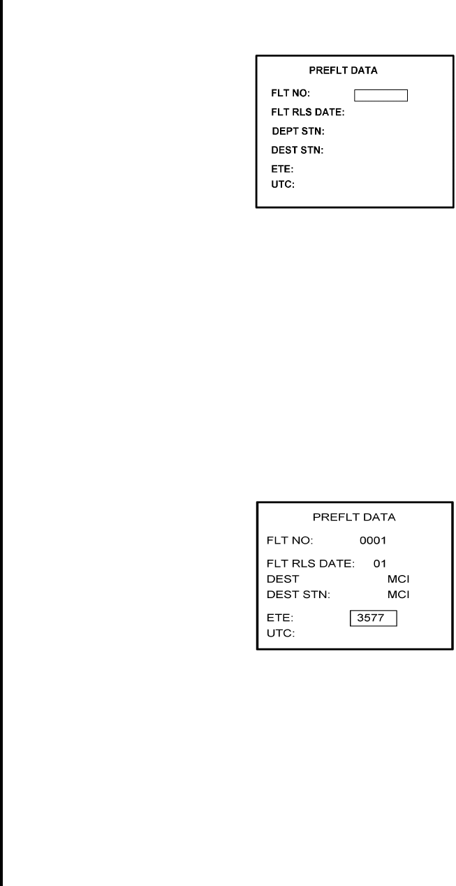
(b) If ACARS page shown in Figure 4-102 appears, press “1" key and the PREFLIGHT
Data page, Figure 4-104 will appear. Otherwise proceed to step 4(h).
Figure 4-104
(c) Insert a one digit number (eg. 1) in FLT NO: field and press ENTER key. Cursor will
move FLT RLS DATE: field.
(d) Insert a one digit number (eg. 1) in FLT RLS DATE: field and press ENTER key.
Cursor will move to DEPT STN: field.
(e) Insert a three character departure station identifier (eg. MCI) in DEPT STN: field and
press ENTER key. Cursor will move to DEPT STN: field.
(f) Insert a three character destination station identifier (eg. MCI) in DEST STN: field
and press ENTER key. Cursor will move to ETE field.
(g) Enter 3577 in ETE field and press ENTER key. See Figure 4-105. Proceed to step 5.
Figure 4-105
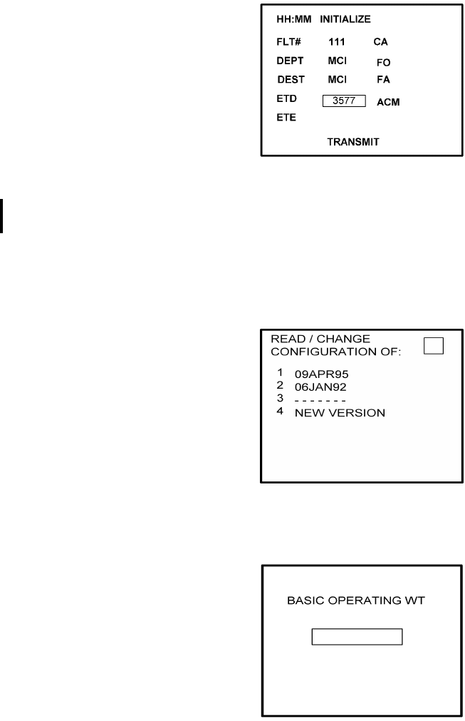
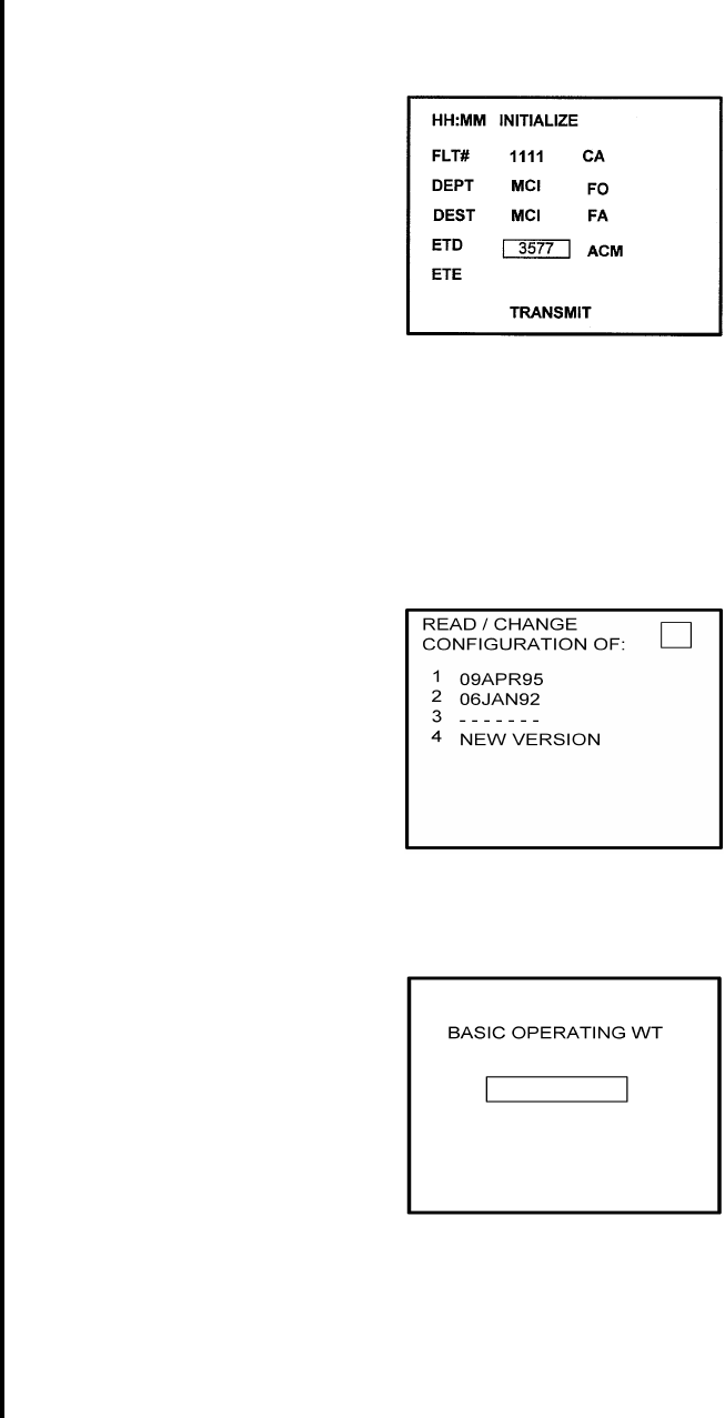
(h) Insert a three digit number (eg. 111) in FLT# field and press ENTER key. Cursor will
move to DEPT field (see Figure 4-106).
(i) Insert a three character departure identifier (eg. MCI) in DEPT field and press
ENTER key. Cursor will move to DEST field.
(j) Insert a three character destination identifier (eg MCI) in DEST field and press
ENTER key. Cursor will move to ETD field.
Global
AIRBORNE FLIGHT INFORMATION SYSTEM
IMAFISJWA 4-47
March/2001
(k) Enter 3577 in ETD field and press ENTER key. See Figure 4-106 and proceed to
step 5.
Figure 4-106
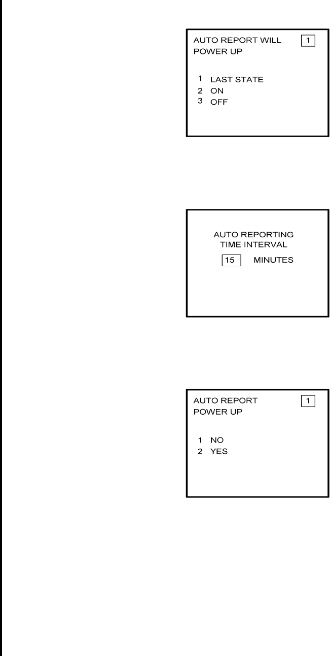
5. Select the AFIS configuration to be read or modified from the AFIS Configuration Menu
Page (Figure 4-107) and press the ENTER Key.
The dates of previously entered configurations are shown in Options 1 to 3. The
newest configuration date appears first. Option 4 allows for the entry of a new
configuration. Select Options 1 to 4 as desired and Figure 4-108 will be displayed.
Figure 4-107
6. Insert the basic operating weight and press ENTER. See Figure 4-108.
Figure 4-108

Global
AIRBORNE FLIGHT INFORMATION SYSTEM
IMAFISJWA 4-48
March/2001
7. Insert the default for Auto Report and press ENTER. See Figure 4-109.
Figure 4-109
8. Insert 15 as the Auto Reporting time interval unless advised differently by the
pilot/operator and press ENTER. See Figure 4-110.
Figure 4-110
9. Select Option 1 if reports are not wanted on the ground. Select Option 2 if reports on
the ground are required. See Figure 4-111.
Figure 4-111
Global
AIRBORNE FLIGHT INFORMATION SYSTEM
IMAFISJWA 4-49
March/2001
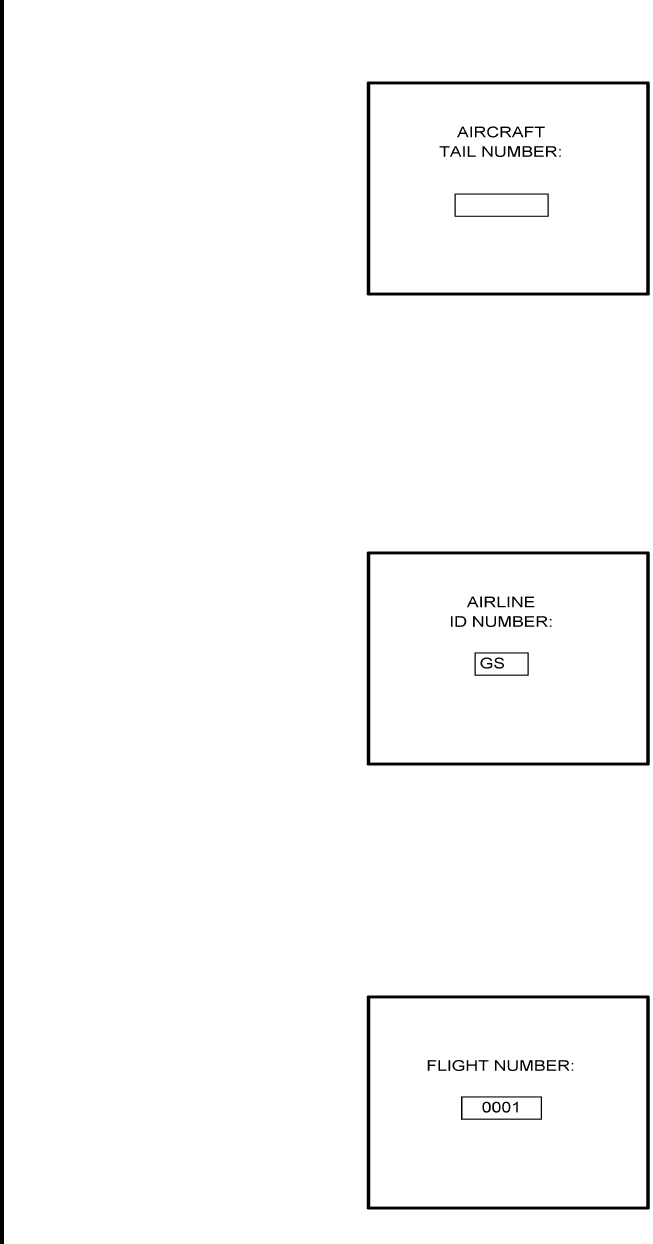
10. Insert complete aircraft registration number (tail number) in the cursor field and press
ENTER. See Figure 4-112.
Figure 4-112
11. Insert GS as the Airline ID number and press ENTER. See Figure 4-113.
NOTE:
Currently, GS is the only valid entry except for the following: XJ for
MESABA Airlines, DH for Atlantic Coast Aviation, Part Numbers
400-045500-0003 or 400-045500-0130 ONLY.
Figure 4-113
12. In the Flight Number cursor field, insert the number 0001 as shown in Figure 4-114.
Press ENTER.
NOTE:
Currently, 0001 is the only valid entry and may change at a future time.
Figure 4-114
Global
AIRBORNE FLIGHT INFORMATION SYSTEM
IMAFISJWA 4-50
March/2001
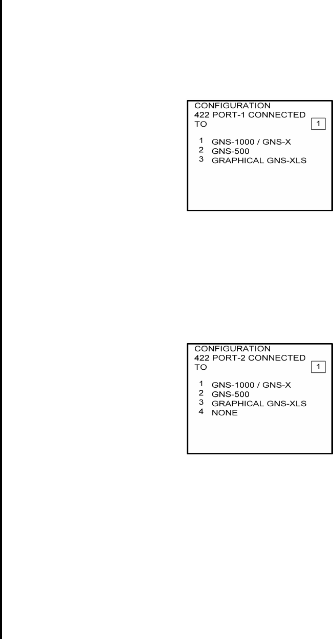
13. Insert 1 as shown in Figure 4-115 to indicate that Port 1 is connected to the GNS-1000,
GNS-X, or other manufactures navigation system and press ENTER.
NOTE:
GNS-X applies also to GNS-XES, GNS-XL and GNS-XLS.
Figure 4-115
14. If applicable, insert 1 to designate that Port 2 is connected to the GNS-1000 or GNS-X
system. Press ENTER. If no Global systems are connected, select Option 4. See
Figure 4-116.
NOTE:
GNS-X applies also to GNS-XES, GNS-XL and GNS-XLS.
Figure 4-116
Global
AIRBORNE FLIGHT INFORMATION SYSTEM
IMAFISJWA 4-51
March/2001
15. If applicable, insert 1 to designate that Port 3 is connected to the GNS-1000 or GNS-X
system. Press ENTER. If no Global systems are connected, select Option 4. See
Figure 4-117.
NOTE:
GNS-X applies also to GNS-XES, GNS-XL and GNS-XLS.
Figure 4-117
16. To designate Port 1 as the Master 422 Port, insert 1 and press ENTER. See Figure
4-118.
NOTE:
The master port refers to the use of one port by the software to have priority
over the data from other ports (i.e. CDU2). Honeywell recommends use of
Port 1.
Figure 4-118
17. The 429 port option is only applicable when other manufacturer’s navigation systems
are installed. If only Global systems are used, insert 3 and press ENTER. See Figure
4-119.
Figure 4-119
Global
AIRBORNE FLIGHT INFORMATION SYSTEM
IMAFISJWA 4-52
March/2001
18. The 429 port option is only applicable when other manufacturer’s navigation systems
are installed. If only Global systems are used, insert 3 and press ENTER. See Figure
4-120.
Figure 4-120
19. The 429 port option is only applicable when other manufacturer’s navigation systems
are installed. If only Global systems are used, insert 3 and press ENTER. See Figure
4-121.
Figure 4-121
20. Select whether the AFIS system is using a separate antenna and press ENTER. See
Figure 4-122.
NOTE:
The Antenna Switching Unit (ASU) allows the AFIS system to share an
antenna with the VHF Comm or use its own antenna.
Figure 4-122
Global
AIRBORNE FLIGHT INFORMATION SYSTEM
IMAFISJWA 4-53
March/2001
21. Insert type designator as listed in Table 4-1 and press ENTER. See Figure 4-123.
NOTE:
If the aircraft type is not listed in Table 4-1, contact Global Data Center to
obtain type designator.
Figure 4-123
22. Select Option 1 for ARINC network or Option 2 for SITA or AVICOM network. Press
ENTER to continue. See Figure 4-124.
Figure 4-124
23. Fuel Flow option is not available for GNS-1000, GNS-X, GNS-XES, GNS-XL or
GNS-XLS. Insert 1 and press the ENTER Key. See Figure 4-125. If DMU P/N
400-045500-0004, 400-045500-0006 or other NAV system is used, select the
appropriate fuel flow pages.
Figure 4-125
Global
AIRBORNE FLIGHT INFORMATION SYSTEM
IMAFISJWA 4-54
March/2001
24. Fuel Flow option is not available for GNS-1000, GNS-X, GNS-XES, GNS-XL or
GNS-XLS. Select 1 and press the ENTER Key. See Figure 4-126.
Figure 4-126
25. Select the applicable special feature option and press the ENTER Key to continue.
(a) If Airline ID of GS has been entered the special selection features page will appear
as in Figure 4-127.
NOTE:
OFF/ON REPORTS = logging takeoff and landing times. OPTION 1 =
customer defined non-standard AFIS features. OFF REPORT = logging
takeoff times. NO OFF/ON REPORTS = no logging of takeoff and landing
times.
Figure 4-127
Global
AIRBORNE FLIGHT INFORMATION SYSTEM
IMAFISJWA 4-55
March/2001
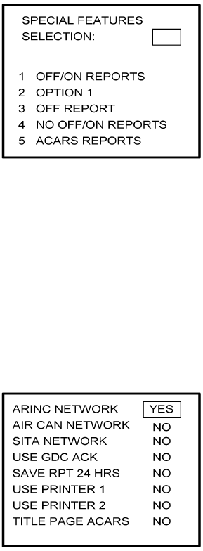
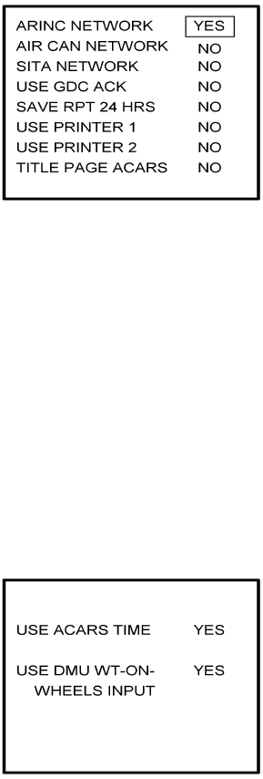
(b) If Airline ID XJ or DH has been inserted the special feature option will be displayed as
Figure 4-128.
NOTE:
OFF/ON REPORTS = logging takeoff and landing times. OPTION 1 =
customer defined non-standard AFIS features. OFF REPORT = logging
takeoff times. NO OFF/ON REPORTS = no logging of takeoff and landing
times. ACARS REPORTS = Customer defined non-standard AFIS
features.
Figure 4-128
NOTE:
If Airline ID is GS, ACARS reports can be accessed by pressing *A or *M
and then pressing ENTER key.
If ACARS REPORTS, 5, has been selected see Figure 4-129 otherwise
proceed to step 27.
(c) If Airline ID of DH or *A has been entered, the following page selections will be
available.
Figure 4-129
Global
AIRBORNE FLIGHT INFORMATION SYSTEM
IMAFISJWA 4-56
March/2001
Use UP or DOWN arrow keys or right hand line select keys to position cursor over
selections. Depress BACK key to cycle between YES and No selection. Press
ENTER key to select. Cursor will move to next entry below selection. If cursor is on
TITLE PAGE ACARS selection, then pressing ENTER key will activate the page
shown in Figure 4-130.
BACK key - depressed with cursor off page causes SPECIAL FEATURES selection
to appear. ENTER key - depressed with cursor off page causes screen shown in
Figure 4-130 to appear.
Figure 4-130
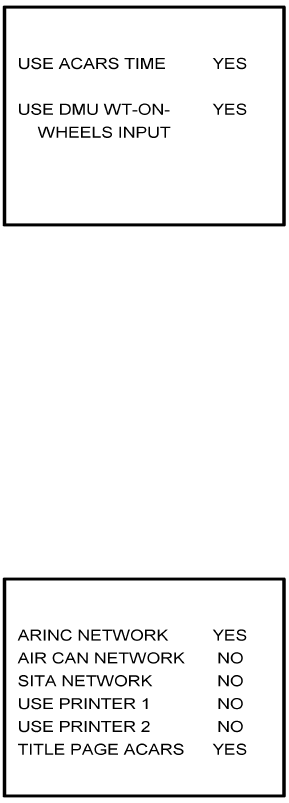
Use UP or Down arrow or right hand LINE SELECT keys to position cursor over
option.
BACK key - depressed to cycle between YES and NO with cursor over desired
selection. ENTER key - depress to select. Cursor will move to next entry below
selection. If over USE DMU WT-ON-WHEELS INPUT selection, pressing ENTER
key will proceed to step 27.
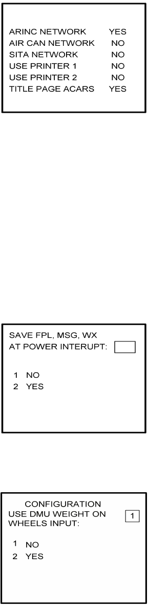
(d) If Airline ID of XJ or *M has been entered, the following configuration selection will
be available. See Figure 4-131.
Figure 4-131
Use UP or Down arrow or right hand LINE SELECT keys to position cursor over
selections.
BACK key - depressed to cycle between YES and NO with cursor over desired
selection.
Global
AIRBORNE FLIGHT INFORMATION SYSTEM
IMAFISJWA 4-57
March/2001
ENTER key - depress to select. Cursor will move to next entry below selection. If over
TITLE PAGE ACARS selection, pressing ENTER key will display the page shown in
Figure 4-130.
26. Select whether stored flight plans, messages and weather will be retained in memory
when power is interrupted. Press the ENTER Key to continue. See Figure 4-132.
Figure 4-132
27. Select the desired option for Auto Weather update status at power up and press the
ENTER Key. See Figure 4-133.
Figure 4-133
Global
AIRBORNE FLIGHT INFORMATION SYSTEM
IMAFISJWA 4-58
March/2001
28. This step is only applicable to GNS-1000, GNS-X, GNS-XES, GNS-XL or GNS-XLS with
Satellite Data Communication System option DMU P/N 400-045500-0003,
400-045500-0004, 400-045500-0005, 400-045500-0006 or 400-045500-0130.
If other versions of the DMU are used, proceed to Step 30. If applicable, select Satcom
Option 2 and press the ENTER Key. See Figure 4-134.
Select GWS option for AERO-C satellite system, ARINC 741 for Aeronautical Standard
(ARINC 741) satellite system and SATFONE for SATFONE system. ARINC 741 and
SATFONE can only be selected when using DMU P/N 400-045500-0005 or
400-045500-0006.
Figure 4-134
29. Select the desired option and press the ENTER Key. See Figure 4-135.
Figure 4-135
30. Write configuration data to the Configuration Module by selecting 2 and press the
ENTER Key. See Figure 4-136.
Figure 4-136
31. Power Off DMU and restart.
Global
AIRBORNE FLIGHT INFORMATION SYSTEM
IMAFISJWA 4-59
March/2001
4.5 CONFIGURATION MODULE PROGRAMMING FOR GNS-1000, GNS-X, GNS-XES,
GNS-XL OR GNS-XLS WITH DMU P/N 400-045500-0210 OR 400-045500-2010.
1. Install test connector P/N 12870-1 to the front of the DMU on J102.
2. Turn system on. Press the ENTER Key to accept DATE, GMT, and Position.
If DMU has been previously configured for ACARS proceed to step 4(a) otherwise step 3.
3. Press the PLAN Key or AFIS Key to display the AFIS MENU Page. See Figures 4-137
through 4-139.
Figure 4-137
Figure 4-138
Figure 4-139
AFIS MENU
1. WX GRAPHICS
2. TERMINAL WX
3. SIGMETS
4. WINDS ALOFT
5. AFIS FLT PLAN
6. RECALL AFIS FPL
7. SEND AFIS MESSAGE
8. DISPL AFIS MSG
9. OPERATING MODES
Global
AIRBORNE FLIGHT INFORMATION SYSTEM
IMAFISJWA 4-60
March/2001
4. Use the UP or DOWN Arrow Key or Line >Select keys to position the cursor over the
RECALL AFIS FPL option and press the ENTER Key. The RECALL AFIS FPL Page
appears. Use the UP or DOWN Arrow Key or Line Select keys to position the cursor
over the DATE field and enter 357777. Press the ENTER Key. See Figure 4-140.
Figure 4-140
NOTE:
For non-ACARS programming, proceed to step 5.
(a) Press the PLAN key or AFIS key to display the ACARS page. See Figure 4-141 or
4-142.
Figure 4-141
Figure 4-142
Global
AIRBORNE FLIGHT INFORMATION SYSTEM
IMAFISJWA 4-61
March/2001
(b) If ACARS page shown in Figure 4-141 appears, press “1" key and the PREFLIGHT
Data page, Figure 4-143 will appear. Otherwise proceed to step 4(h).
Figure 4-143
(c) Insert a one digit number (eg. 1) in FLT NO: field and press ENTER key. Cursor will
move FLT RLS DATE: field.
(d) Insert a one digit number (eg. 1) in FLT RLS DATE: field and press ENTER key.
Cursor will move to DEPT STN: field.
(e) Insert a three character departure station identifier (eg. MCI) in DEPT STN: field and
press ENTER key. Cursor will move to DEPT STN: field.
(f) Insert a three character destination station identifier (eg. MCI) in DEST STN: field
and press ENTER key. Cursor will move to ETE field.
(g) Enter 3577 in ETE field and press ENTER key. See Figure 4-144. Proceed to step 5.
Figure 4-144
(h) Insert a three digit number (eg. 111) in FLT# field and press ENTER key. Cursor will
move to DEPT field.
(i) Insert a three character departure identifier (eg. MCI) in DEPT field and press
ENTER key. Cursor will move to DEST field.
(j) Insert a three character destination identifier (eg MCI) in DEST field and press
ENTER key. Cursor will move to ETD field.
Global
AIRBORNE FLIGHT INFORMATION SYSTEM
IMAFISJWA 4-62
March/2001
(k) Enter 3577 in ETD field and press ENTER key. See Figure 4-145 and proceed to
step 5.
Figure 4-145
5. Select the AFIS configuration to be read or modified from the AFIS Configuration Menu
Page (Figure 4-146) and press the ENTER Key.
The dates of previously entered configurations are shown in Options 1 to 3. The
newest configuration date appears first. Option 4 allows for the entry of a new
configuration. Select Options 1 to 4 as desired and Figure 4-146 will be displayed.
Figure 4-146
6. Insert the basic operating weight and press ENTER. See Figure 4-147.
Figure 4-147
Global
AIRBORNE FLIGHT INFORMATION SYSTEM
IMAFISJWA 4-63
March/2001
7. Insert the default for Auto Report and press ENTER. See Figure 4-148.
Figure 4-148
8. Insert 15 as the Auto Reporting time interval unless advised differently by the
pilot/operator and press ENTER. See Figure 4-149.
Figure 4-149
9. Select Option 1 if reports are not wanted on the ground. Select Option 2 if reports on
the ground are required. See Figure 4-150.
Figure 4-150
Global
AIRBORNE FLIGHT INFORMATION SYSTEM
IMAFISJWA 4-64
March/2001
10. Insert complete aircraft registration number (tail number) in the cursor field and press
ENTER. See Figure 4-151.
Figure 4-151
11. Insert GS as the Airline ID number and press ENTER. See Figure 4-152.
NOTE:
Currently, GS is the only valid entry except for the following: XJ for
MESABA Airlines, DH for Atlantic Coast Aviation.
Figure 4-152
12. In the Flight Number cursor field, insert the number 0001 as shown in Figure 4-153.
Press ENTER.
NOTE:
Currently, 0001 is the only valid entry and may change at a future time.
Figure 4-153
Global
AIRBORNE FLIGHT INFORMATION SYSTEM
IMAFISJWA 4-65
March/2001
13. Insert 1 as shown in Figure 4-154 to indicate that Port 1 is connected to the GNS-1000,
GNS-X, or other manufactures navigation system or insert 3 if a graphical GNS-XLS is
attached to port 1. Press ENTER.
NOTE:
GNS-X applies also to GNS-XES, GNS-XL and GNS-XLS.
Figure 4-154
14. Insert 1 as shown in Figure 4-1555 to designate that Port 2 is connected to the
GNS-1000, GNS-X or other manufacturers navigation system or insert 3 if a
Graphical GNS-XLS is attached to Port 2. Press ENTER. If no Global systems
are connected, select option 4.
NOTE:
GNS-X applies also to GNS-XES, GNS-XL and GNS-XLS.
Figure 4-155
Global
AIRBORNE FLIGHT INFORMATION SYSTEM
IMAFISJWA 4-66
March/2001
15. If applicable, insert 1 to designate that Port 3 is connected to the GNS-1000 or GNS-X
system or insert 3 if Port 3 is connected to a Graphical GNS-XLS. Press ENTER. If no
Global systems are connected, select Option 4. See Figure 4-156.
NOTE:
GNS-X applies also to GNS-XES, GNS-XL and GNS-XLS.
Figure 4-156
16. To designate Port 1 as the Master 422 port, insert 1 and press ENTER. See Figure
4-157.
NOTE:
The master port refers to the use of one port by the software to have
priority over the data from other ports (i.e. CDU2). Global recommends
use of Port 1.
Figure 4-157
17. The 429 port option is only applicable when other manufacturers navigation systems
are installed. If only Global systems are used, insert 3 and press ENTER. See Figure
4-158.
Figure 4-158
Global
AIRBORNE FLIGHT INFORMATION SYSTEM
IMAFISJWA 4-67
March/2001
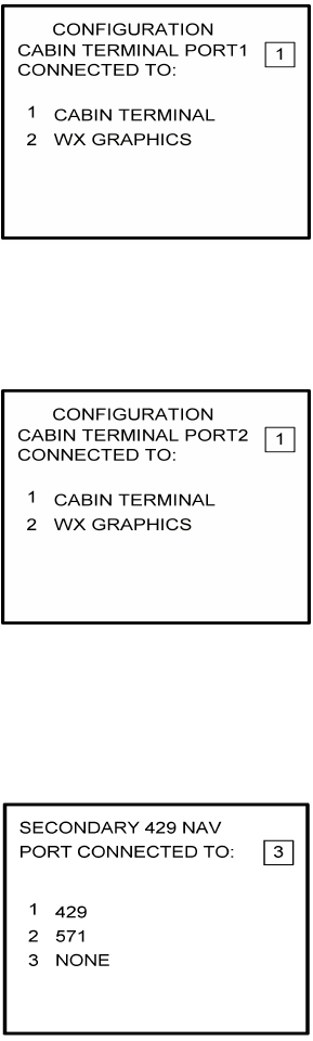
18. Insert a 2 if a weather graphics RPU is connected to Cabin Terminal Port 1. Otherwise,
insert a 1. See Figure 4-159.
Figure 4-159
19. Insert a 2 if a weather graphics RPU is connected to Cabin Terminal Port 2. Otherwise,
insert a 1. See Figure 4-160
Figure 4-160
20. The 429 port option is only applicable when other manufacturer’s navigation systems
are installed. If only Global systems are used, insert 3 and press ENTER. See Figure
4-161.
Figure 4-161
Global
AIRBORNE FLIGHT INFORMATION SYSTEM
IMAFISJWA 4-68
March/2001
21. The 429 port option is only applicable when other manufacturer’s navigation systems
are installed. If only Global systems are used, insert 3 and press ENTER. See Figure
4-162.
Figure 4-162
22. Select whether the AFIS system is using a separate antenna and press ENTER. See
Figure 4-163.
NOTE:
The Antenna Switching Unit (ASU) allows the AFIS system to share an
antenna with the VHF Comm or use its own antenna.
Figure 4-163
23. Insert type designator as listed in Table 4-1 and press ENTER. See Figure 4-164.
NOTE:
If the aircraft type is not listed in Table 4-1, contact Global Data Center to
obtain type designator.
Figure 4-164
Global
AIRBORNE FLIGHT INFORMATION SYSTEM
IMAFISJWA 4-69
March/2001
24. Select Option 1 for ARINC network or Option 2 for SITA or AVICOM network. Press
ENTER to continue. See Figure 4-165.
Figure 4-165
25. Fuel Flow option is not available for GNS-1000, GNS-X, GNS-XES, GNS-XL or
GNS-XLS. Insert 1 and press the ENTER Key. See Figure 4-166. If DMU P/N
400-045500-0004, 400-045500-0006 or other NAV system is used, select the
appropriate fuel flow pages.
Figure 4-166
26. Fuel Flow option is not available for GNS-1000, GNS-X, GNS-XES, GNS-XL or
GNS-XLS. Select 1 and press the ENTER Key. See Figure 4-167.
Figure 4-167
Global
AIRBORNE FLIGHT INFORMATION SYSTEM
IMAFISJWA 4-70
March/2001
27. Select the applicable special feature option and press the ENTER Key to continue.
(a) If Airline ID of GS has been entered the special selection features page will appear
as in Figure 4-168.
NOTE:
OFF/ON REPORTS = logging takeoff and landing times. OPTION 1 =
customer defined non-standard AFIS features. OFF REPORT = logging
takeoff times. NO OFF/ON REPORTS = no logging of takeoff and landing
times.
Figure 4-168
(b) If Airline ID XJ or DH has been inserted the special feature option will be displayed
as Figure 4-169.
NOTE:
OFF/ON REPORTS = logging takeoff and landing times. OPTION 1 =
customer defined non-standard AFIS features. OFF REPORT = logging
takeoff times. NO OFF/ON REPORTS = no logging of takeoff and landing
times. ACARS REPORTS = Customer defined non-standard AFIS
features.
Figure 4-169
NOTE:
If Airline ID is GS, ACARS reports can be accessed by pressing *A or *M
and then pressing ENTER key.
If ACARS REPORTS, 5, has been selected see Figure 4-170 otherwise
proceed to step 28.
Global
AIRBORNE FLIGHT INFORMATION SYSTEM
IMAFISJWA 4-71
March/2001
(c) If Airline ID of DH or *A has been entered, the following page selections will be
available.
Figure 4-170
Use UP or DOWN arrow keys or right hand line select keys to position cursor over
selections. Depress BACK key to cycle between YES and No selection. Press
ENTER key to select. Cursor will move to next entry below selection. If cursor is on
TITLE PAGE ACARS selection, then pressing ENTER key will activate the page
shown in Figure 4-171.
BACK key - depressed with cursor off page causes SPECIAL FEATURES selection
to appear.
ENTER key -depressed with cursor off page causes screen shown in Figure 4-171
to appear.
Figure 4-171
Use UP or Down arrow or right hand LINE SELECT keys to position cursor over
option.
BACK key - depressed to cycle between YES and NO with cursor over desired
selection.
ENTER key - depress to select. Cursor will move to next entry below selection. If over
USE DMU WT-ON-WHEELS INPUT selection, pressing ENTER key
will proceed to step 27.
Global
AIRBORNE FLIGHT INFORMATION SYSTEM
IMAFISJWA 4-72
March/2001
(d) If Airline ID of XJ or *M has been entered, the following configuration selection will
be available. See Figure 4-172.
Figure 4-172
Use UP or Down arrow or right hand LINE SELECT keys to position cursor over
selections.
BACK key - depressed to cycle between YES and NO with cursor over desired
selection.
ENTER key - depress to select. Cursor will move to next entry below selection. If over
TITLE PAGE ACARS selection, pressing ENTER key will display the
page shown in Figure 4-171.
28. Select whether stored flight plans, messages and weather will be retained in memory
when power is interrupted. Press the ENTER Key to continue. See Figure 4-173.
Figure 4-173
29. Insert 2 if the DMU is to use the weight on wheels input. See Figure 4-174.
Figure 4-174
Global
AIRBORNE FLIGHT INFORMATION SYSTEM
IMAFISJWA 4-73
March/2001
30. Select the desired option for Auto Weather update status at power up and press the
ENTER Key. See Figure 4-175.
Figure 4-175
31. This step is only applicable to GNS-1000, GNS-X, GNS-XES, GNS-XL or GNS-XLS with
Satellite Data Communication System option DMU P/N 400-045500-0210 or
400-045500-2010.
If other versions of the DMU are used, proceed to Step 33. If applicable, select Satcom
Option 2 and press the ENTER Key. See Figure 4-176.
Select GWS option for AERO-C satellite system, ARINC 741 for Aeronautical Standard
(ARINC 741) satellite system and SATFONE for SATFONE system. ARINC 741 and
SATFONE can only be selected when using DMU P/N 400-045500-2010.
Figure 4-176
32. Select the desired option and press the ENTER Key. See Figure 4-177.
Figure 4-177
Global
AIRBORNE FLIGHT INFORMATION SYSTEM
IMAFISJWA 4-74
March/2001
33. Write configuration data to the Configuration Module be selecting 2 and press the
ENTER Key. See Figure 4-178.
Figure 4-178
34. Power Off DMU and restart.
NOTE:
This completes AFIS configuration. For ACARS configuration, proceed to step 4(a).
Global
AIRBORNE FLIGHT INFORMATION SYSTEM
IMAFISJWA 4-75
March/2001
4.6 CONFIGURATION MODULE PROGRAMMING FOR GNS-1000, GNS-X, GNS-XES,
GNS-XL OR GNS-XLS WITH DMU P/N 400-045500-0211 OR 400-045500-2011.
1. Install test connector P/N 12870-1 to the front of the DMU on J102.
2. Turn system on. Press the ENTER Key to accept DATE, GMT, and Position.
If DMU has been previously configured for ACARS proceed to step 4(a) otherwise step 3.
3. Press the PLAN Key or AFIS Key to display the AFIS MENU Page. See Figures 4-179
through 4-181.
Figure 4-179
Figure 4-180
Figure 4-181
AFIS MENU
1. WX GRAPHICS
2. TERMINAL WX
3. SIGMETS
4. WINDS ALOFT
5. AFIS FLT PLAN
6. RECALL AFIS FPL
7. SEND AFIS MESSAGE
8. DISPL AFIS MSG
9. OPERATING MODES
Global
AIRBORNE FLIGHT INFORMATION SYSTEM
IMAFISJWA 4-76
March/2001
4. Use the UP or DOWN Arrow Key or Line >Select keys to position the cursor over the
RECALL AFIS FPL option and press the ENTER Key. The RECALL AFIS FPL Page
appears. Use the UP or DOWN Arrow Key or Line Select keys to position the cursor
over the DATE field and enter 357777. Press the ENTER Key. See Figure 4-182.
Figure 4-182
NOTE:
For non-ACARS programming, proceed to step 5.
(a) Press the PLAN key or AFIS key to display the ACARS page. See Figure 4-183 or
4-184.
Figure 4-183
Figure 4-184
Global
AIRBORNE FLIGHT INFORMATION SYSTEM
IMAFISJWA 4-77
March/2001
(b) If ACARS page shown in Figure 4-183 appears, press “1" key and the PREFLIGHT
Data page, Figure 4-185 will appear. Otherwise proceed to step 4(h).
Figure 4-185
(c) Insert a one digit number (eg. 1) in FLT NO: field and press ENTER key. Cursor will
move FLT RLS DATE: field.
(d) Insert a one digit number (eg. 1) in FLT RLS DATE: field and press ENTER key.
Cursor will move to DEPT STN: field.
(e) Insert a three character departure station identifier (eg. MCI) in DEPT STN: field and
press ENTER key. Cursor will move to DEPT STN: field.
(f) Insert a three character destination station identifier (eg. MCI) in DEST STN: field
and press ENTER key. Cursor will move to ETE field.
(g) Enter 3577 in ETE field and press ENTER key. See Figure 4-186. Proceed to step 5.
Figure 4-186
(h) Insert a four digit number (eg. 1111) in FLT# field and press ENTER key. Cursor will
move to DEPT field.
(i) Insert a three character departure identifier (eg. MCI) in DEPT field and press
ENTER key. Cursor will move to DEST field.
(j) Insert a three character destination identifier (eg MCI) in DEST field and press
ENTER key. Cursor will move to ETD field.
Global
AIRBORNE FLIGHT INFORMATION SYSTEM
IMAFISJWA 4-78
March/2001
(k) Enter 3577 in ETD field and press ENTER key. See Figure 4-145 and proceed to
step 5.
Figure 4-187
5. Select the AFIS configuration to be read or modified from the AFIS Configuration Menu
Page (Figure 4-188) and press the ENTER Key.
The dates of previously entered configurations are shown in Options 1 to 3. The
newest configuration date appears first. Option 4 allows for the entry of a new
configuration. Select Options 1 to 4 as desired and Figure 4-188 will be displayed.
Figure 4-188
6. Insert the basic operating weight and press ENTER. See Figure 4-189.
Figure 4-189
Global
AIRBORNE FLIGHT INFORMATION SYSTEM
IMAFISJWA 4-79
March/2001
7. Insert the default for Auto Report and press ENTER. See Figure 4-190.
Figure 4-190
8. Insert 15 as the Auto Reporting time interval unless advised differently by the
pilot/operator and press ENTER. See Figure 4-191.
Figure 4-191
9. Select Option 1 if reports are not wanted on the ground. Select Option 2 if reports on
the ground are required. See Figure 4-192.
Figure 4-192
Global
AIRBORNE FLIGHT INFORMATION SYSTEM
IMAFISJWA 4-80
March/2001
10. Insert complete aircraft registration number (tail number) in the cursor field and press
ENTER. See Figure 4-193.
Figure 4-193
11. Insert GS as the Airline ID number and press ENTER. See Figure 4-194.
NOTE:
Currently, GS is the only valid entry except for the following: XJ for
MESABA Airlines, DH for Atlantic Coast Aviation.
Figure 4-194
12. In the Flight Number cursor field, insert the number 0001 as shown in Figure 4-195.
Press ENTER.
NOTE:
Currently, 0001 is the only valid entry and may change at a future time.
Figure 4-195
Global
AIRBORNE FLIGHT INFORMATION SYSTEM
IMAFISJWA 4-81
March/2001
13. Insert 1 as shown in Figure 4-196 to indicate that Port 1 is connected to the GNS-1000,
GNS-X, or other manufactures navigation system or insert 3 if a graphical GNS-XLS is
attached to port 1. Press ENTER.
NOTE:
GNS-X applies also to GNS-XES, GNS-XL and GNS-XLS.
Figure 4-196
14. Insert 1 as shown in Figure 4-197 to designate that Port 2 is connected to the
GNS-1000, GNS-X or other manufacturers navigation system or insert 3 if a
Graphical GNS-XLS is attached to Port 2. Press ENTER. If no Global systems
are connected, select option 4.
NOTE:
GNS-X applies also to GNS-XES, GNS-XL and GNS-XLS.
Figure 4-197
Global
AIRBORNE FLIGHT INFORMATION SYSTEM
IMAFISJWA 4-82
March/2001
15. If applicable, insert 1 to designate that Port 3 is connected to the GNS-1000 or GNS-X
system or insert 3 if Port 3 is connected to a Graphical GNS-XLS. Press ENTER. If no
Global systems are connected, select Option 4. See Figure 4-198.
NOTE:
GNS-X applies also to GNS-XES, GNS-XL and GNS-XLS.
Figure 4-198
16. To designate Port 1 as the Master 422 port, insert 1 and press ENTER. See Figure
4-199.
NOTE:
The master port refers to the use of one port by the software to have
priority over the data from other ports (i.e. CDU2). Global recommends
use of Port 1.
Figure 4-199
17. Insert a 2 if a weather graphics RPU is connected to Cabin Terminal Port 1. Otherwise,
insert a 1. See Figure 4-200.
Figure 4-200
Global
AIRBORNE FLIGHT INFORMATION SYSTEM
IMAFISJWA 4-83
March/2001
18. Insert a 2 if a weather graphics RPU is connected to Cabin Terminal Port 2. Otherwise,
insert a 1. See Figure 4-201
Figure 4-201
19. The 429 port option is only applicable when other manufacturers navigation systems
are installed. If only Global systems are used, insert 3 and press ENTER. See Figure
4-202.
Figure 4-202
20. The 429 port option is only applicable when other manufacturer’s navigation systems
are installed. If only Global systems are used, insert 3 and press ENTER. See Figure
4-203.
Figure 4-203
Global
AIRBORNE FLIGHT INFORMATION SYSTEM
IMAFISJWA 4-84
March/2001
21. The 429 port option is only applicable when other manufacturer’s navigation systems
are installed. If only Global systems are used, insert 3 and press ENTER. See Figure
4-204.
Figure 4-204
22. Select whether the AFIS system is using a separate antenna and press ENTER. See
Figure 4-205.
NOTE:
The Antenna Switching Unit (ASU) allows the AFIS system to share an
antenna with the VHF Comm or use its own antenna.
Figure 4-205
23. Insert type designator as listed in Table 4-1 and press ENTER. See Figure 4-206.
NOTE:
If the aircraft type is not listed in Table 4-1, contact Global Data Center to
obtain type designator.
Figure 4-206
Global
AIRBORNE FLIGHT INFORMATION SYSTEM
IMAFISJWA 4-85
March/2001
24. Select Option 1 for ARINC network or Option 2 for SITA or AVICOM network. Press
ENTER to continue. See Figure 4-207.
Figure 4-207
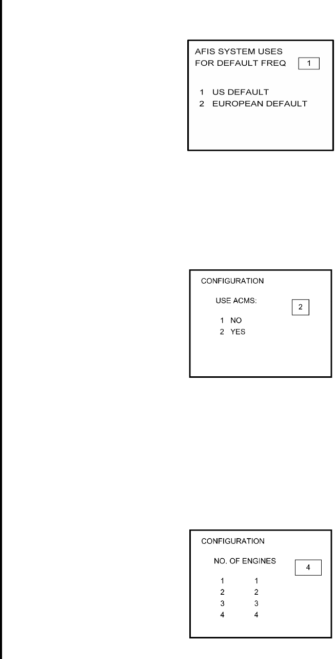
25. Select Option 2 if ACMS (FDAMS) hardware will be installed. Press ENTER key to
continue. See Figure 4-208.
NOTE:
If option 1 is selected, skip to step 28.
Figure 4-208
26. Select number of engines applicable. Press ENTER key to continue. See Figure
4-209.
NOTE:
This menu operation has been modified from its prior use in the Fuel Flow
Menus.
Figure 4-209
Global
AIRBORNE FLIGHT INFORMATION SYSTEM
IMAFISJWA 4-86
March/2001
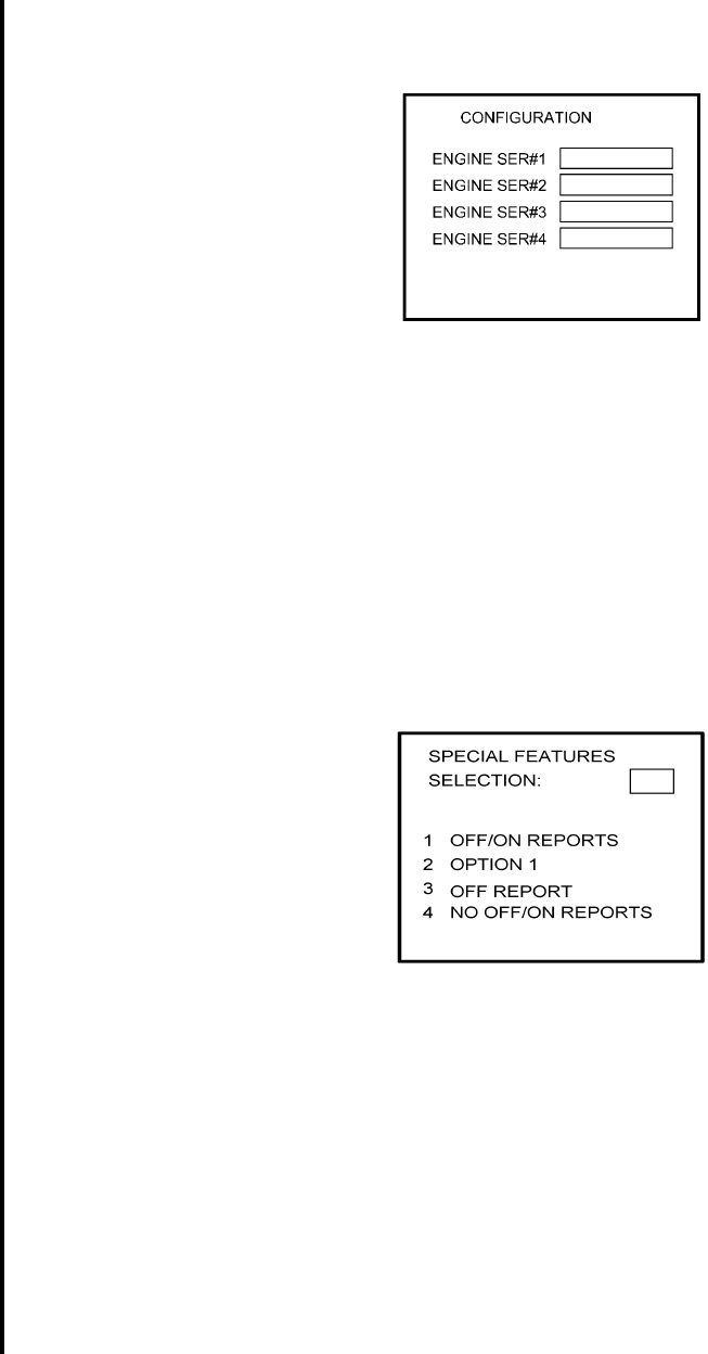
27. Insert 1-4 Engine Serial Numbers based on number entered in Step 26. Press ENTER
key to continue. See Figure 4-210.
Figure 4-210
28. Select the applicable special feature option and press the ENTER Key to continue.
(a) If Airline ID of GS has been entered the special selection features page will appear
as in Figure 4-211.
NOTE:
OFF/ON REPORTS = logging takeoff and landing times. OPTION 1 =
customer defined non-standard AFIS features. OFF REPORT = logging
takeoff times. NO OFF/ON REPORTS = no logging of takeoff and landing
times.
Figure 4-211
Pressing the ENTER key will proceed to step 31.
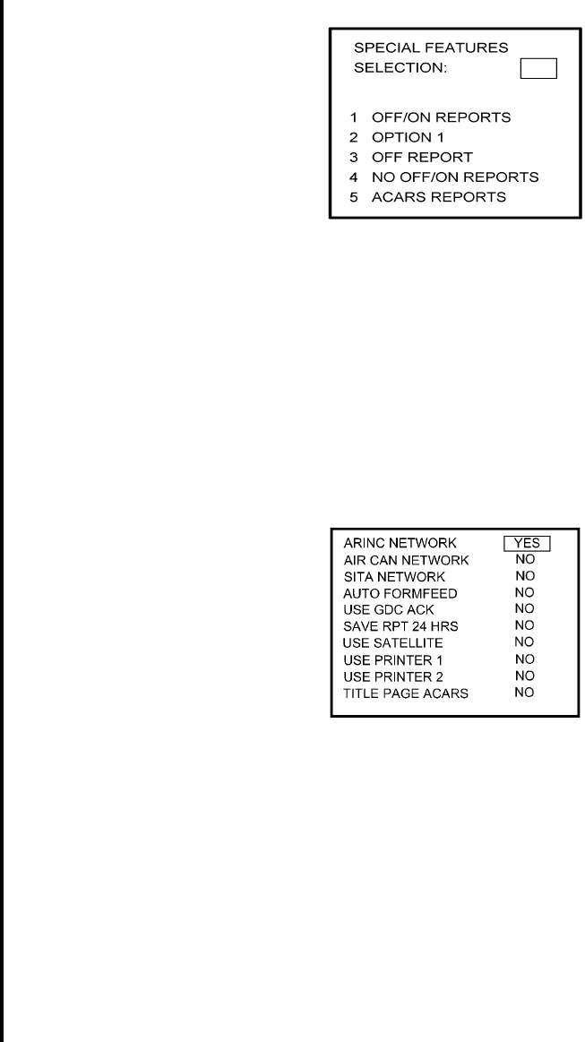
(b) If Airline ID XJ or DH has been inserted the special feature option will be displayed
as Figure 4-212.
NOTE:
OFF/ON REPORTS = logging takeoff and landing times. OPTION 1 =
customer defined non-standard AFIS features. OFF REPORT = logging
takeoff times. NO OFF/ON REPORTS = no logging of takeoff and landing
times. ACARS REPORTS = Customer defined non-standard AFIS
features.
Global
AIRBORNE FLIGHT INFORMATION SYSTEM
IMAFISJWA 4-87
March/2001
Figure 4-212
NOTE:
If Airline ID is GS, ACARS reports can be accessed by pressing *A or *M
and then pressing ENTER key.
If ACARS REPORTS, 5, has been selected, see Figure 4-213 for Airline ID
DH or see Figure 4-215 for Airline ID XJ; otherwise, proceed to step 31.
(c) If Airline ID of DH or *A has been entered, the following page selections will be
available.
Figure 4-213
Use UP or DOWN arrow keys or right hand line select keys to position cursor over
selections. Depress BACK key to cycle between YES and No selection. Press
ENTER key to select. Cursor will move to next entry below selection. If cursor is on
TITLE PAGE ACARS selection, then pressing ENTER key will activate the page
shown in Figure 4-214.
BACK key - depressed with cursor off page causes SPECIAL FEATURES selection
to appear.
ENTER key -depressed with cursor off page causes screen shown in Figure 4-214
to appear.
Global
AIRBORNE FLIGHT INFORMATION SYSTEM
IMAFISJWA 4-88
March/2001
Figure 4-214
Use UP or Down arrow or right hand LINE SELECT keys to position cursor over
option.
NOTE:
For airline ID of DH or *A, set OFF OR ON TRIGGERED BY: to 2.
BACK key - depressed to cycle between YES and NO with cursor over USE ACARS
TIME.
ENTER key - depress to select. Cursor will move to next entry below selection. If over
OFF OR ON TRIGGERED BY: selection, pressing ENTER key will
proceed to step 32.
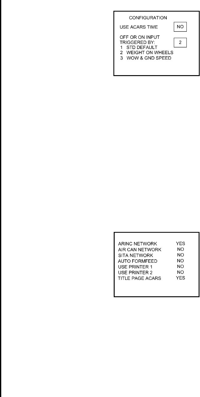
(d) If Airline ID of XJ or *M has been entered, the following configuration selection will
be available. See Figure 4-215.
Figure 4-215
Use UP or Down arrow or right hand LINE SELECT keys to position cursor over
selections.
BACK key - depressed to cycle between YES and NO with cursor over desired
selection. depressed with cursor off page causes SPECIAL
FEATURES selection to appear.
Global
AIRBORNE FLIGHT INFORMATION SYSTEM
IMAFISJWA 4-89
March/2001
ENTER key - depress to select. Cursor will move to next entry below selection. If over
TITLE PAGE ACARS selection, pressing ENTER key will display the
page shown in Figure 4-216
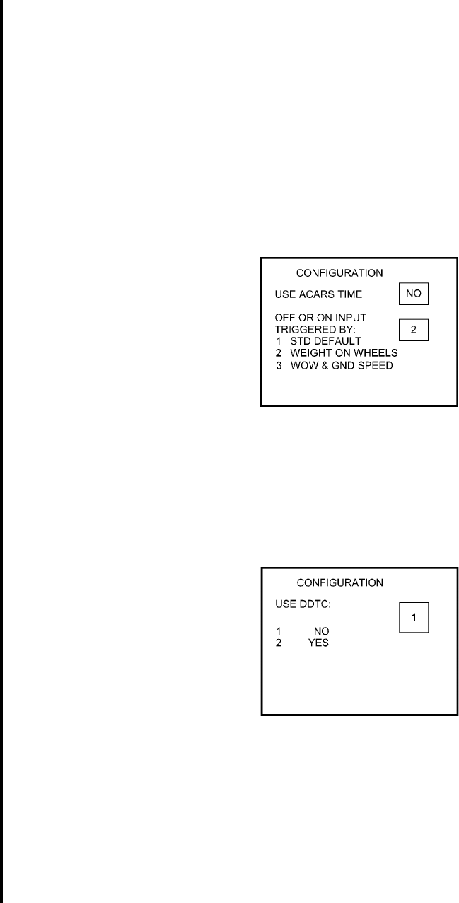
29. Select applicable inputs for use ACARS TIME and OFF OR ON TRIGGERED BY.
NOTE:
If Airline ID of XJ or *M has been entered, set use ACARS TIME to NO
using BACK key and insert 2 for OFF OR ON TRIGGERED BY. See Figure
4-216.
Figure 4-216
Press ENTER key from OFF OR ON TRIGGERED BY to continue to next page
30. Select 1 to disable DDTC (taxi clearance) and Pushback Request options; otherwise,
select option 2. Press ENTER. See Figure 4-217.
Figure 4-217
Pressing the ENTER key will proceed to step 32.
Global
AIRBORNE FLIGHT INFORMATION SYSTEM
IMAFISJWA 4-90
March/2001
31. Select whether the AFIS system is using standard default (ground speed) or weight on
wheels to trigger in-air detection. Enter selection and press ENTER (see Figure 4-218)
Figure 4-218
NOTE:
After making a selection, go to step 32.
32. Select whether stored flight plans, messages and weather will be retained in memory
when power is interrupted. Press the ENTER Key to continue. See Figure 4-218.
Figure 4-219
33. Select the desired option for Auto Weather update status at power up and press the
ENTER Key. See Figure 4-220.
Figure 4-220
34. This step is only applicable to GNS-1000, GNS-X, GNS-XES, GNS-XL or GNS-XLS with
Satellite Data Communication System option DMU P/N 400-045500-0211 or
400-045500-2011.
If other versions of the DMU are used, proceed to Step 36. If applicable, select Satcom
Option 2 and press the ENTER Key. See Figure 4-221.
Global
AIRBORNE FLIGHT INFORMATION SYSTEM
IMAFISJWA 4-91
March/2001
Select AERO-C option for AERO-C satellite system, ARINC 741 for Aeronautical
Standard (ARINC 741) satellite system and SATFONE for SATFONE system. ARINC
741 and SATFONE can only be selected when using DMU P/N 400-045500-2011.
Figure 4-221
35. Select the desired option and press the ENTER Key. See Figure 4-222.
Figure 4-222
36. Write configuration data to the Configuration Module be selecting 2 and press the
ENTER Key. See Figure 4-223.
Figure 4-223
37. Power Off DMU and restart.
NOTE:
This completes AFIS configuration. For ACARS configuration, proceed to step 4(a).
Global
AIRBORNE FLIGHT INFORMATION SYSTEM
IMAFISJWA 4-92
March/2001
4.7 CONFIGURATION MODULE PROGRAMMING FOR 739 MCDU AND OTHER FMS
MANUFACTURERS WITH DMU P/N 400-45000-2011 OR 400-45000-0211
1. Install test connector P/N 12870-1 to the front of the DMU on J102.
2. Turn system on.
If DMU has been configured for ACARS proceed to step 5 otherwise go to step 3.
3. Press line-select-key L4 to access Recall FPL Page. See Figure 4-224.
Figure 4-224
4. Enter 357777 on scratch pad, line 13, and press L3. See figure 4-225. Go to step 5.
Figure 4-225
012345678901234567890123
0AF I S MENU
1
L1 2<FLT PLAN FPL L I ST> - R1
3
L2 4<TERMI NAL WX FLT PRG> - R2
5
L3 6<WI NDS ALOFT S I GMENT S > - R3
7
L4 8<RECALL FPL UPDT FPL> - R4
9
L5 0< SEND MSG D I SPLAY MSG> - R5
1
L6 2<OPERAT I NG MODES - R6
3
012345678901234567890123
0RECALL AF I S FPL 1 / 1
1FPL NUMBER
L1 2XXXXX - R1
3
L2 4-R2
5DATE FROM
L3 611NOV98 KDEN- R3
7ETD TO
L4 801:11 KLAX- R4
9
L5 0-R5
1
L6 2<ME NU TRAN SM I T > - R6
3357777
Global
AIRBORNE FLIGHT INFORMATION SYSTEM
IMAFISJWA 4-93
March/2001
5. Enter 3577 in line 13 and press L4. See figure 4-226.
Figure 4-226
6. Enter six numeric digits represent day, month, and year and press line-select-key L3.
See Figure4-227.
Figure 4-227
012345678901234567890123
0HH : MM I N I T I AL I Z E 1 / 1
1FLT # CA
L1 2AAAA XXXXX - R1
3DEP T F O
L2 4KKK ZZZZZ - R2
5DES T F A
L3 6YYY TTTTT - R3
7ETD A CM
L4 8DDDD RRRRR - R4
9ETE
L5 0L+L L -R5
1
L6 2<ME NU TRAN SM I T > - R6
33577
012345678901234567890123
0CONF I GURAT I ON 1 / 1 1
1
L1 2-R1
3
L2 4-R2
5DAT E : D A Y M O N T H Y E A R
L3 62 2 0 8 9 9 -R3
7
L4 8-R4
9
L5 0-R5
1
L6 2<ME N U N E X T> - R6
3230899
Global
AIRBORNE FLIGHT INFORMATION SYSTEM
IMAFISJWA 4-94
March/2001
7. Select the AFIS configuration to be read or modified from the AFIS configuration Menu
Page (Figure 4-228) by pressing adjacent line-select-key. The dates of previously
entered configurations are shown in Option 1 to 3. The newest configuration date
appears first. Option 4 allows for the entry of a new configuration. Select Option 1 to
4 as desired and Figure 4-229 will be displayed.
Figure 4-228
8. See Figure 4-229 and perform the following steps:
a. Enter complete aircraft registration number (tail number) in the scratch pad line 13
and press line-select-key L1.
b. Enter aircraft id in the scratch pad line 13 and press line-select-key L3.
c. Enter flight number in line 13 and press line-select-key L5.
d. Press line-select-key R6 to go to the next page.
Figure 4-229
012345678901234567890123
0CONF I GURAT I ON 1 / 1 1
1READ / CHANGE
L1 2CONF I GURAT I ON OF : - R1
3
L2 4<1 D D M M Y Y -R2
5
L3 6<2 D D M M Y Y -R3
7
L4 8<3 D D M M Y Y -R4
9
L5 0<4 N E W V E R S I O N -R5
1
L6 2<MENU - R6
3
012345678901234567890123
0CONF I GURAT I ON 2 / 1 1
1A I RCRAFT TA I L NUMBER
L1 2XXXXXXX - R1
3
L2 4-R2
5AIR C R A F T I D N U M B E R
L3 6XX -R3
7
L4 8-R4
9FL I G H T N U M B E R
L5 0XXX X -R5
1
L6 2<PREVIOUS NEXT> - R6
3
Global
AIRBORNE FLIGHT INFORMATION SYSTEM
IMAFISJWA 4-95
March/2001
9. See Figure 4-230 and perform the following steps:
a. Enter aircraft type in the scratch pad line 13 and press line-select-key L1.
b. Enter basic operating weight in the scratch pad line 13 and press line-select-key L2.
c. Press line-select-key L3 to toggle separate antenna to yes or no.
d. Press line-select-key L4 to toggle default frequency between U.S. DEFAULT and
EUROPEAN DEFAULT.
e. Press line-select-key R6 to go to the next page.
Figure 4-230
10. See Figure 4-231 and perform the following steps:
a. Press line-select-key L1 to toggle the default for Auto RPT Will PWR Up between last
state, on, or off.
b. Enter the Auto Reporting time interval unless advised differently by the pilot/operator
in the scratch pad line 13 and press line-select-key L3.
c. Press line-select-key L3 to toggle the Auto Reporting on Ground between YES, and
NO.
d. Press line-select-key R6 to go to the next page.
Figure 4-231
012345678901234567890123
0CONF I GURAT I ON 3 / 1 1
1A I R C R A F T T Y P E
L1 2XXXXXXX -R1
3B A S I C O P E R A T I N G W T
L2 4XXXXXX -R2
5S E P A R A T E A N T E N N A
L3 6* Y E S -R3
7D E F A U L T F R E Q U E N C Y
L4 8* U . S . D E F A U L T -R4
9
L5 0-R5
1
L6 2<PREVIOUS NEXT> - R6
3
012345678901234567890123
0CONF I GURAT I ON 4 / 1 1
1A U T O R P T W I L L P W R U P
L1 2* L A S T S T A T E -R1
3
L2 4-R2
5A U T O R P T T I M E I N T E R V A L
L3 6X X M I N U T E S -R3
7
L4 8-R4
9A U T O R E P O R T I N G O N G N D
L5 0* Y E S -R5
1
L6 2<PREVIOUS NEXT> - R6
3
Global
AIRBORNE FLIGHT INFORMATION SYSTEM
IMAFISJWA 4-96
March/2001
11. See Figure 4-232 and perform the following steps:
a. Press line-select-key L1 to toggle the default for Port 1 between GNS-1000/GNS-X
and GNS-500.
b. Press line-select-key L3 to toggle the default for Port 2 between GNS-1000/GNS-X
and GNS-500
c. Press line-select-key L5 to toggle the default for Port 3 between GNS-1000/GNS-X,
GNS-500, and NONE.
d. Press line-select-key R6 to go to the next page.
Figure 4-232
12. See Figure 4-233 and perform the following steps:
a. Press line-select-key L1 to toggle the default for Port 1 between 429, 571, and OFF.
b. Press line-select-key L3 to toggle the default for Port 2 between 429, 571, and OFF.
c. Press line-select-key L5 to toggle the default for Port 3 between 429, 571, and OFF.
d. Press line-select-key R6 to go to the next page.
NOTE:
For 739 MCDU select L1 or L2 or L3 to indicate which port is connected.
012345678901234567890123
0CONF I GURAT I ON 5 / 1 1
14 2 2 P O R T - 1 C O N N E C T E D :
L1 2* G N S - 1 0 0 0 / G N S - X -R1
3
L2 4-R2
54 2 2 P O R T - 2 C O N N E C T E D :
L3 6* G N S - 5 0 0 -R3
7
L4 8-R4
94 2 2 P O R T - 3 C O N N E C T E D :
L5 0* N O N E -R5
1
L6 2<PREVIOUS NEXT> - R6
3
Global
AIRBORNE FLIGHT INFORMATION SYSTEM
IMAFISJWA 4-97
March/2001
Figure 4-233
13. Select whether stored flight plans, messages and weather will be retained in memory
when power is interrupted. See Figure 4-234.
a. Press line-select-key L1 to toggle the default for Auto Weather Will PWR Up between
LAST STATE, ON, and OFF.
b. Press line-select-key L3 to toggle the default for Save FPL, MSG, WX between YES
or NO.
c. Press line-select-key R6 to go to the next page.
Figure 4-234
14. This step is only applicable to GNS-1000, GNS-X, GNS-XES, GNS-XL or GNS-XLS
with Satellite Date Communication System option DMU P/N 400-045500-2011. If
other versions of the DMU are used, proceed to step 15. If applicable, select Satcom
AERO-C Option for Honeywell satellite system, ARINC741 for Aeronautical Standard
(ARINC 741) satellite system and SATFONE for SATFONE system. ARINC 741 and
SATFONE can only be selected when using DMU P/N 400-045500-2011.
012345678901234567890123
0CONF I GURAT I ON 6 / 1 1
14 2 9 P R I M A R Y P O R T I S :
L1 2* 4 2 9 -R1
3
L2 4-R2
54 2 9 S E C O N D A R Y P O R T I S :
L3 6* 5 7 1 -R3
7
L4 8-R4
94 2 9 T E R T I A R Y P O R T I S :
L5 0* O F F -R5
1
L6 2<PREVIOUS NEXT> - R6
3
012345678901234567890123
0CONF I GURAT I ON 7 / 1 1
1A U T O W E A T H E R W I L L P W R U P
L1 2* L A S T S T A T E -R1
3
L2 4S A V E F P L , M S G , W X A T P W R -R2
5I N T E R R U P T ?
L3 6* Y E S -R3
7
L4 8-R4
9
L5 0-R5
1
L6 2<PREVIOUS NEXT> - R6
3
Global
AIRBORNE FLIGHT INFORMATION SYSTEM
IMAFISJWA 4-98
March/2001
See Figure 4-235.
a. Press line-select-key L1 to toggle the default for SAT System Available between NO,
AERO-C, ARINC741, and SATFONE.
b. Press line-select-key L3 to toggle the default for SAT Network Will PWR Up between
LAST STATE, ON or OFF.
c. Press line-select-key R6 to go to the next page.
Figure 4-235
15. The master port refers to the use of one port by the software to have priority over the
data from other ports (i.e. CDU 2). Honeywell recommends use of Port 1. To
designate Port 1 as the Master 422 Port, toggle line-select-key L1 until Port 1 is
displayed, see Figure 4-236.
a. Press line-select-key L3 to toggle the Use DMU WT-ON-WHEEL Input between YES
or NO.
b. If Airline ID XJ, DH or CRJ has been entered, the ACARS REPORTS will be one of
the available options when L5 is toggling through the feature selection options.
c. If Airline ID is GS, ACARS REPORTS can be accessed by entering .A or .M on the
scratch pad, line 13, and then press line-select-key L5.
NOTE:
OFF/ON REPORTS = logging takeoff and landing times/
OPTION 1 = customer defined non-standard AFIS features.
OFF REPORT = logging takeoff times.
NO OFF/ON REPORTS = no logging of takeoff and landing times.
ACARS REPORTS = Customer defined non-standard AFIS features.
d. Press line-select-key R6 to go to the next page.
012345678901234567890123
0CONF I GURAT I ON 8 / 1 1
1S A T S Y S T E M A V A I L A B L E :
L1 2* A E R O - C -R1
3
L2 4-R2
5S A T N E T W O R K W I L L P W R U P:
L3 6* L A S T S T A T E -R3
7
L4 8-R4
9
L5 0-R5
1
L6 2< P R E V I O U S N E X T >- R6
3
Global
AIRBORNE FLIGHT INFORMATION SYSTEM
IMAFISJWA 4-99
March/2001
Figure 4-236
16. If ACARS REPORT has been selected, see Figure 4-237; otherwise, proceed to step
17.
If Airline ID of DH or CRJ or .A has been entered, the following page selections will be
available.
Figure 4-237
17. Use adjacent line-select-key to toggle and select the configuration items.
Press line-select-key R6 to go to the next page (See Figure 4-238).
If Airline ID of XJ or .M has been entered, the following page selections will be
available.
012345678901234567890123
0CONF I GURAT I ON 9 / 1 1
1M A S T E R 4 2 2 P O R T I S
L1 2* P O R T 1 -R1
3
L2 4-R2
5U S E D M U W T - O N - W H E E L I N PT
L3 6* Y E S -R3
7
L4 8-R4
9F E A T U R E S E L E C T I O N
L5 0* N O O N / O F F R E P O R T S -R5
1
L6 2< P R E V I O U S N E X T >- R6
3
012345678901234567890123
0CONF I GURAT I ON 1 0 / 1 1
1A R I N C U S E S A T E L L I T E
L1 2* Y E S Y E S* - R1
3S I T A U S E G D C A CK
L2 4* Y E S Y E S* - R2
5A T O F O R M F E E D T I T L E A C A RS
L3 6* N O Y E S* - R3
7P R I N T E R 1 S A V E R PT
L4 8* Y E S Y E S* - R4
9P R I N T E R 2 A C A R S T I ME
L5 0* Y E S N O *-R5
1
L6 2<PREVIOUS NEXT> - R6
3
Global
AIRBORNE FLIGHT INFORMATION SYSTEM
IMAFISJWA 4-100
March/2001
Figure 4-238
18. Use adjacent line-select-key to toggle and select the configuration items.
Press line-select-key R6 to go to the next page.
Write configuration data to the Configuration Module by pressing L3. See Figure
4-239.
Figure 4-239
19. Power Off DMU and restart.
012345678901234567890123
0CONF I GURAT I ON 1 0 / 1 1
1A R I N C T I T L E A C A R S
L1 2* Y E S Y E S *-R1
3S I T A A C A R S T I M E
L2 4* Y E S N O *-R2
5A T O F O R M F E E D
L3 6* N O -R3
7P R I N T E R 1
L4 8* Y E S -R4
9P R I N T E R 2
L5 0* Y E S -R5
1
L6 2<PREVIOUS NEXT> - R6
3
012345678901234567890123
0CONF I GURAT I ON 1 1 / 1 1
1W R I T E C O N F I G U R A T I O N
L1 2D A T A T O M O D U L E ? -R1
3
L2 4< N O -R2
5
L3 6< Y E S -R3
7
L4 8-R4
9
L5 0-R5
1
L6 2<PREVIOUS - R6
3
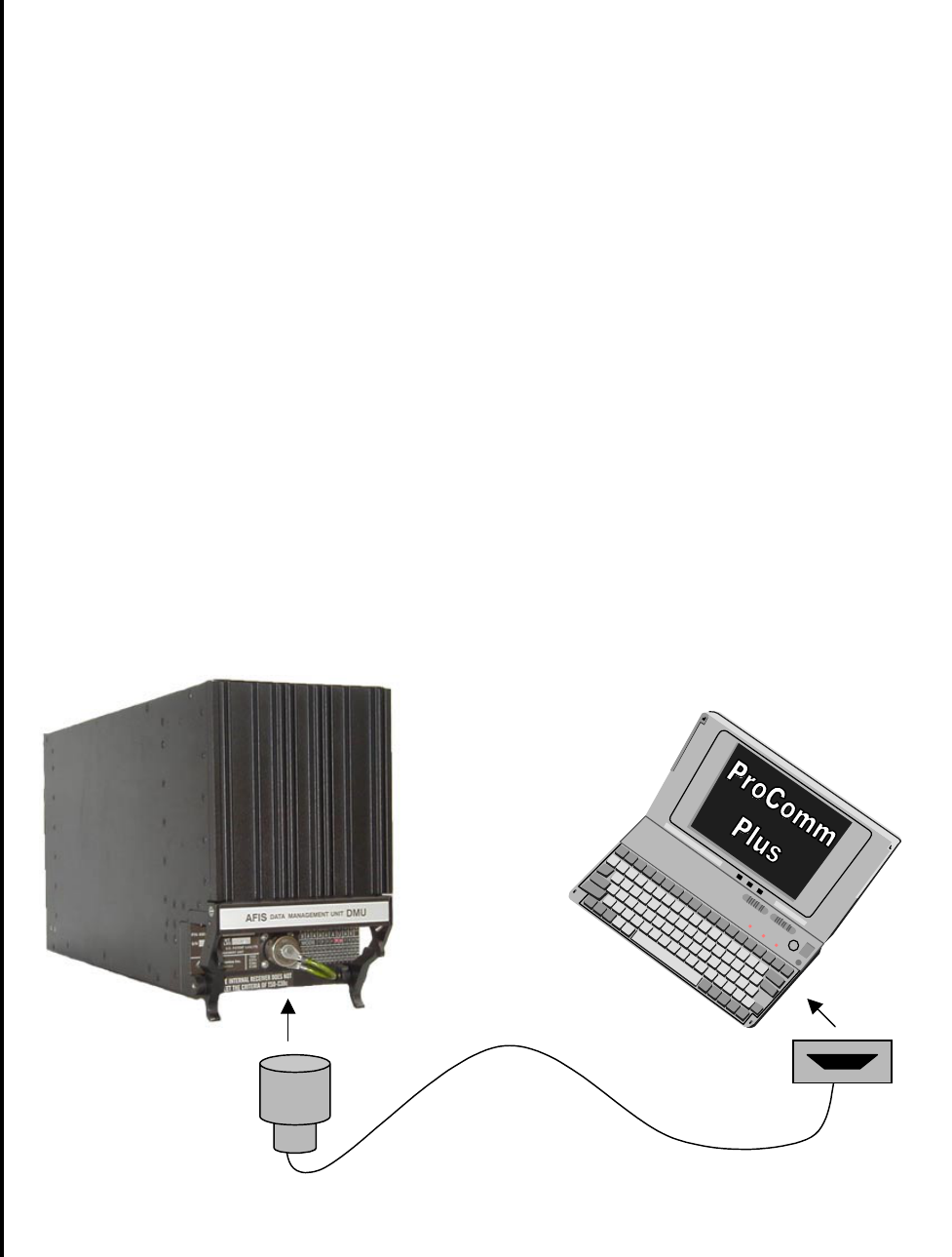
Global
AIRBORNE FLIGHT INFORMATION SYSTEM
IMAFISJWA 4-101
March/2001
4.8 AFIS DATA MANAGEMENT UNIT (DMU) (ProComm Plus Reconfiguration Procedure)
4.8.1 General
This section contains instructions for configuring the AFIS DMU through the test port using a
personal computer (PC) and Symantec Corporation’s ProComm Plus for Windows software. The
aircraft specific configuration settings reside on the configuration module, not in the DMU itself.
Access to the configuration module is through the DMU test port via a PC (laptop computer) using
the interconnect cable (see figure 4-240) described herein. An advantage of storing the
configuration settings on a configuration module is to allow easy replacement or exchange of the
DMU without having to reconfigure the DMU each time it’s removed.
NOTE:
The purpose of this aid is to provide information on configuring the AFIS
system using ProComm Plus software and a laptop computer. It is
assumed that the user will be able to install ProComm Plus according the
manufacturers recommended procedure. There are numerous versions of
ProComm Plus software, this procedure is general in nature and readers
may find some incongruity depending on the version of ProComm being
used.
Figure 4-240
Interconnect Cable
13-pin 9-Pin or
25-Pin
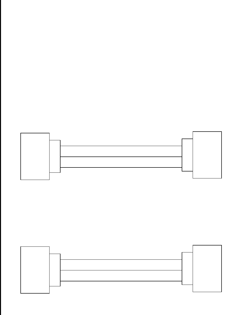
Global
AIRBORNE FLIGHT INFORMATION SYSTEM
IMAFISJWA 4-102
March/2001
4.8.2 Equipment Required
A. AFIS System. DMU P/N 400-045500-XXXX Mod 6 and above.
B. Computer: (IBM or compatible 386, 486, or higher.
1. Windows 3.1 or higher in enhanced mode.
2. A minimum of 4 Megabytes of RAM.
3. Operating system PC-DOS or MS-DOS, version 3.1 or higher.
C. ProComm Plus (for Windows software.
D. User Fabricated Interconnect cable.
The user may construct the interconnect cable wiring to accommodate either a 9-Pin
serial or 25-Pin D-Sub PC RS-232 serial port depending on system availability. Pinouts
for both are described below.
Figure 4-241
Test Port to 9-Pin PC Connector Pinout Diagram
Figure 4-242
Test Port to 25-Pin PC Connector Pinout Diagram
TEST PORT PC
2
3
1
3
2
5
RS-232 IN RS-232 OUT
RS-232 OUT RS-232 IN
GROUND
Connector
P/N
12870-1
TEST PORT PC
2
3
1
2
3
7
RS-232 IN RS-232 OUT
RS-232 OUT RS-232 IN
GROUND
Connector
P/N
12870-1

Global
AIRBORNE FLIGHT INFORMATION SYSTEM
IMAFISJWA 4-103
March/2001
4.8.3 Configuration of Terminal Mode
1. Follow the manufacturer instruction for installing ProComm Plus.
2. Run the ProComm Plus program. (Note: If you’re using a DOS version, it will be
necessary to change to the PCPLUS directory from the DOS prompt)
3. The Terminal Window should now be displayed.
4. Select Port Settings from the Setup Menu, or access Port Settings with the command
ALT-P (see figure 4-243).
5. Set your Port settings as follows:
a) BAUD RATE: 9600
b) PARITY: None
c) DATA BIT: 8
d) STOP BITS: 1
e) DUPLEX: Full
f) BREAK LENGTH: 5 or 350 millisecs
g) SOFTWARE FLOW CONTROL (Xon/Xoff): Set Off
h) Save your settings (ALT-S to save).
6. Set your Data Modem/Connection Settings as follows:
a) Select Connection Setup.
b) Select the local Comm port to be used (unique to your PC).
c) Deselect the following:
1) Use Modem Pacing
2) Drop DTR to hang up
3) Drop DTR between calls
4) Use hardware flow control
d) Ensure that the baud rate is set at 9600.
7. Click on Terminal Options and ensure that the following are selected: (see figure 4-244).
a) Current Terminal: ADM31,TVI925, or TVI950.
b) Terminal Update: Incremental
c) Terminal Size: Rows 24, Columns 80
d) Terminal Keyboard file: ADM31,TVI925, or TVI950.
e) Enquiry OFF
f) Keep cursor in view
g) Screen scroll
h) Strip bit 8
i) Destructive Backspace
j) Tab stops every 8 positions
k) Line wrap
l) Incoming CR to CR/LF
m) Block cursor
n) Disable host printing
8) Click OK or enter ALT-S to save and return to the Terminal Window.
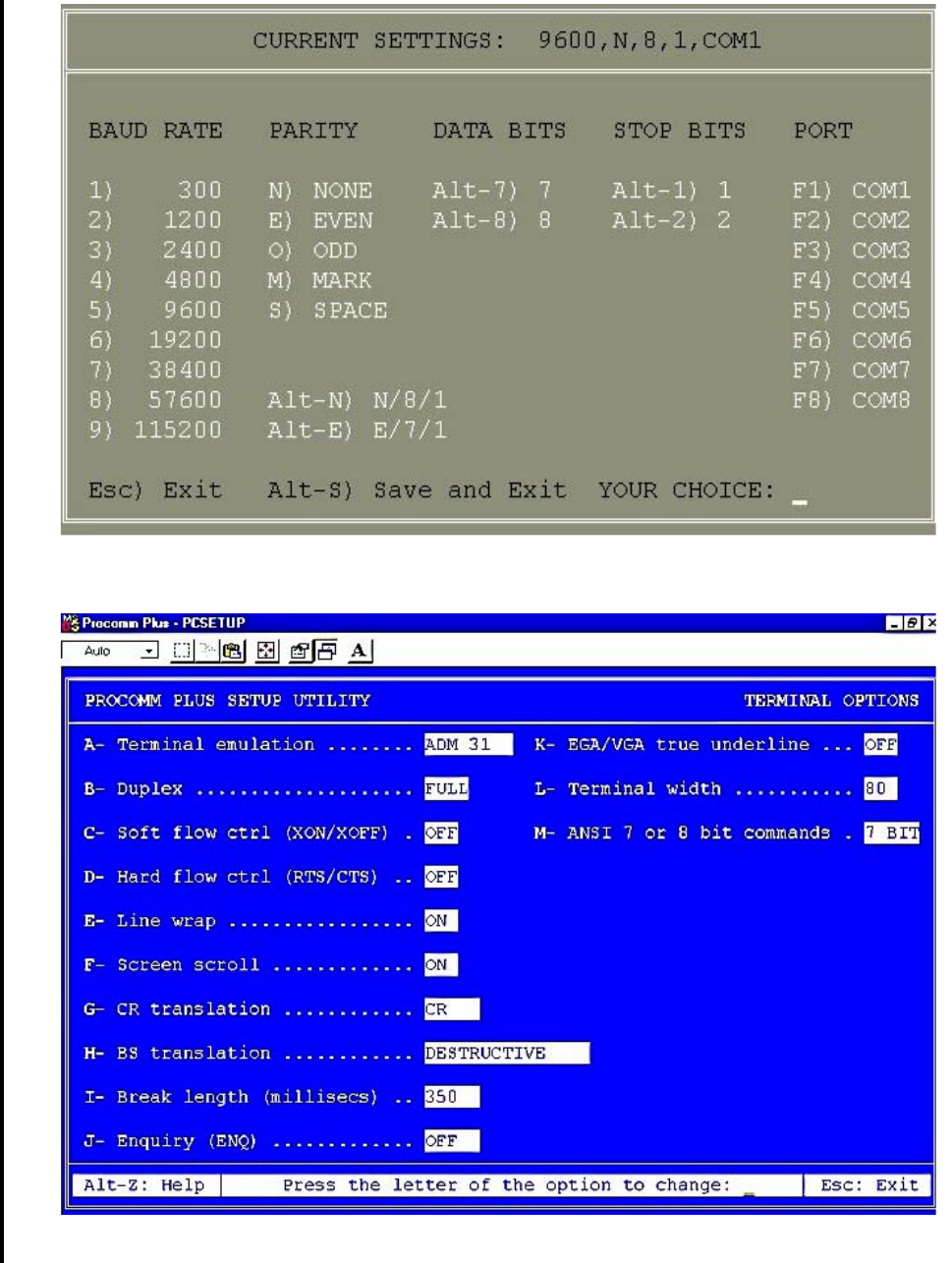
Global
AIRBORNE FLIGHT INFORMATION SYSTEM
IMAFISJWA 4-104
March/2001
Figure 4-243
Sample Port Settings
Figure 4-244
Sample Terminal Options
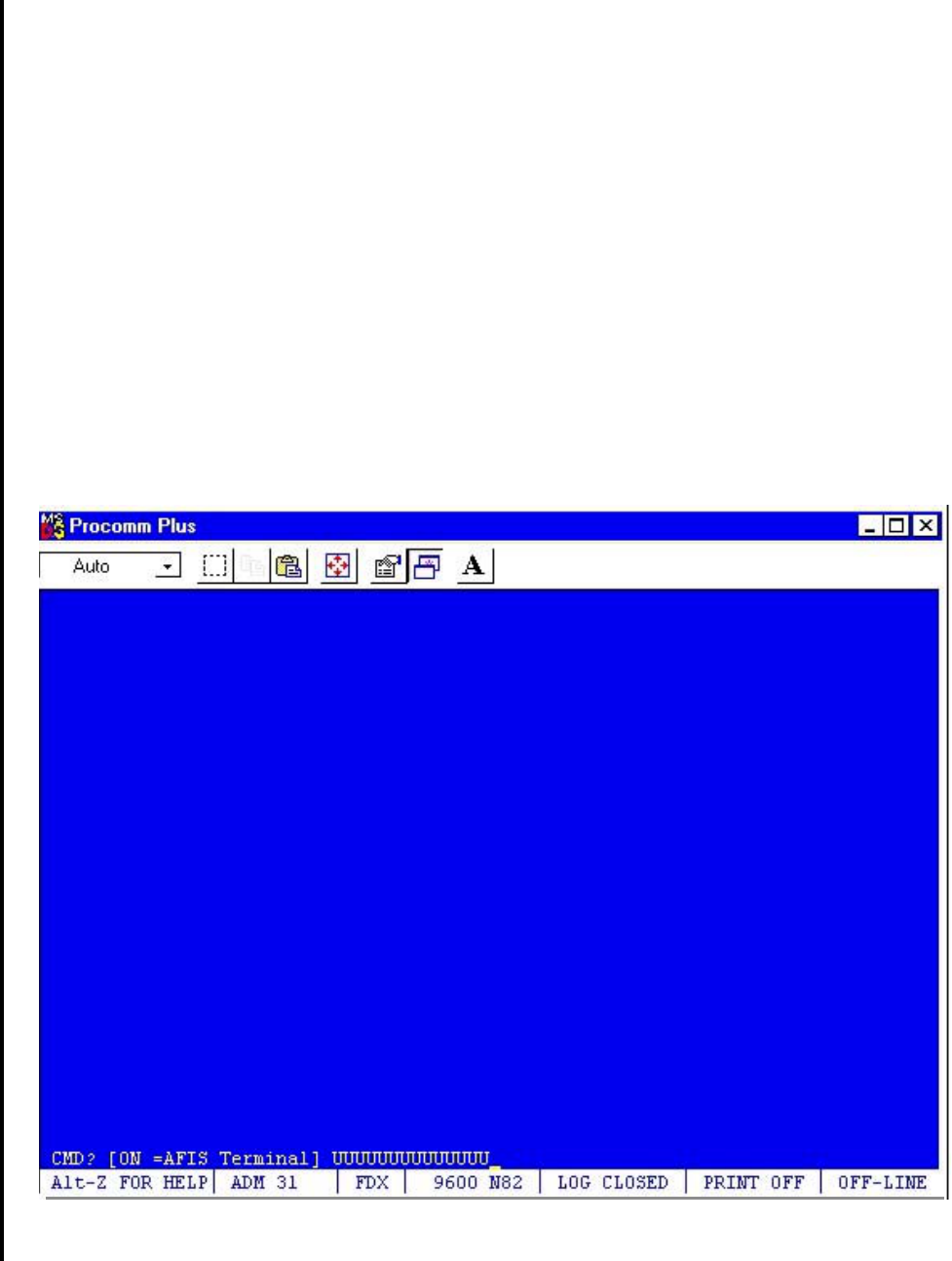
Global
AIRBORNE FLIGHT INFORMATION SYSTEM
IMAFISJWA 4-105
March/2001
4.8.4 Programming the AFIS DMU
1) Attach the interconnect cable to the DMU Test Port, and to the laptop.
2) Start the ProComm program. Windows users click the ProComm Plus icon to get to
the Terminal Window.
3) Apply power to the DMU. The DMU will indicate that it is ready by sending a string of U’s
which appear on the screen at the CMD prompt as indicated in figure 4-245 below.
NOTE:
The Caps Lock on your computer keyboard must be locked "ON".
Figure 4-245
Terminal Window
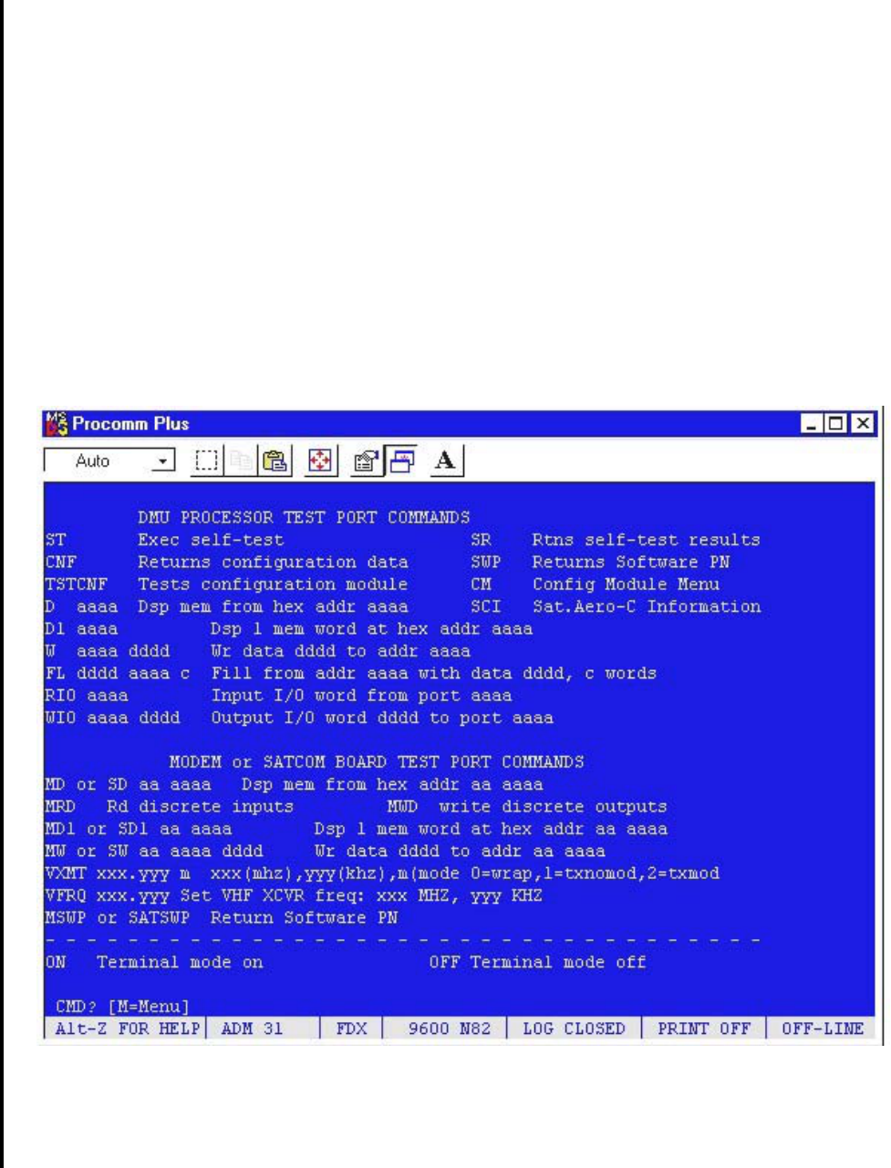
Global
AIRBORNE FLIGHT INFORMATION SYSTEM
IMAFISJWA 4-106
March/2001
4) Type ON to open the AFIS Terminal.
5) Press ENTER. The message “terminal mode on” will appear briefly followed by the
terminal display (see figure 4-246 below).
Figure 4-246
Terminal Display Page
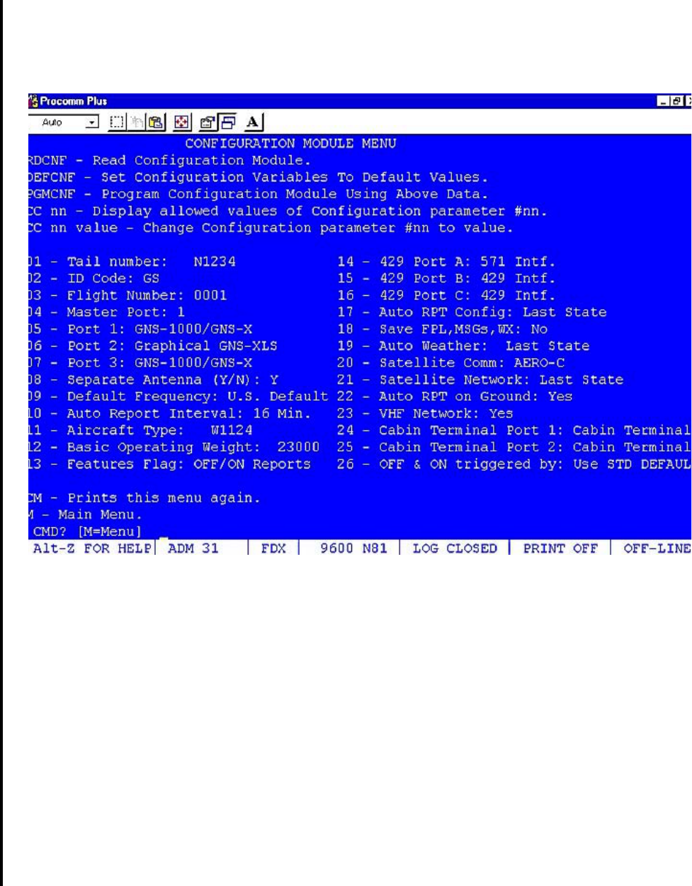
Global
AIRBORNE FLIGHT INFORMATION SYSTEM
IMAFISJWA 4-107
March/2001
6) From the command line, type CM
7) Press ENTER
8) The Configuration Module Menu will be displayed (see figure 4-247 below).
Figure 4-247
Configuration Module Menu
9) For specifics on choosing the parameters shown above please reference the appropriate
section of the AFIS Installation manual. To change a parameter, at the CMD prompt type:
CC NN VALUE (then press ENTER)
Where:
CC = Change Configuration
NN = The two-digit line number you wish to change
VALUE = The parameter you wish to change/add
NOTE:
To view the parameters which are permitted, type: CC NN (then press
ENTER)
Example:
To change the tail number to N5432, type: CC 01 N5432 (then press ENTER).

Global
AIRBORNE FLIGHT INFORMATION SYSTEM
IMAFISJWA 4-108
March/2001
NOTE:
Don’t forget to use spaces between the CC, NN, and VALUE characters as
shown in the example above.
10) After you are finished changing the configuration data, type: PGMCNF (then press
ENTER) Entering this command will program the AFIS configuration module with the
settings from the ProComm Configuration Module Menu page shown in Figure 4-247
above.
11) The configuration change is now complete. To return to the Main menu, at the command
prompt type: M (then press ENTER).
12) At the command prompt, type: OFF (then press ENTER) to turn off the terminal mode.
13) Turn OFF power the DMU, and close all ProComm Plus windows to exit ProComm.
14) End of Procedure.

Global
AIRBORNE FLIGHT INFORMATION SYSTEM
IMAFISJWA 4-109
March/2001
4.9 GENERAL
This section presents the basic test procedure that should be performed after the AFIS
system has been installed.
If AFIS is installed with a GNS-500A Series 4/5 system, be sure the GNS-500A System
Checkout is done per Report 1228, GNS-500A Series 4/5 Installation Manual, before
performing AFIS checkout.
If AFIS is installed with a GNS-1000 system, be sure the GNS-1000 System Checkout is
done per Report 1158, GNS-1000 Flight Management System Installation Manual, before
performing AFIS checkout.
If AFIS is installed with a GNS-X system, be sure the GNS-X System Checkout is done per
Report 1275, GNS-X NAV Management System Installation Manual, before performing
AFIS checkout.
Verify that AFIS configuration has been performed per Section 4, AFIS CONFIGURATION.
NOTE:
GNS-X applies to GNS-X, GNS-XES, GNS-XL and GNS-XLS. If configured
for ACARS (Special Features item 5), temporarily reconfigure with Airline
ID of GS and Special Features, NO OFF/ON REPORTS (item 4). When
finished with this checkout reconfigure Airline ID and SPECIAL FEATURES
as appropriate.
4.10 SYSTEM TEST AND CHECKOUT WITH CUSTOMER SUPPLIED PRE-PROGRAMMED
AFIS DISK
A. Insert pre-programmed AFIS disk in DTU.
NOTE:
Disk must be programmed for the configured aircraft type and must be
programmed with AFIS Flight Plans.
B. Energize the system to initiate SELF TEST.
C. Press the MSG Key to display System Message page. If the AFIS system cannot
communicate with the Global Navigation System an AFIS LINK FAIL message appears.
See Figure 4-248 and 4-249.
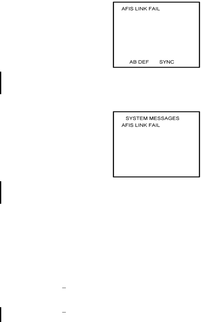
Global
AIRBORNE FLIGHT INFORMATION SYSTEM
IMAFISJWA 4-110
March/2001
GNS-500A
SYSTEM MESSAGE PAGE
Figure 4-248
GNS-1000 OR GNS-X
SYSTEM MESSAGE PAGE
Figure 4-249
1. If the message AFIS LINK FAIL appears on the GNS-500 system message page:
(a) Check aircraft wiring connection between CDU and DMU per Section 3.
(b) Verify that the + 28 VDC is present on the DMU at the appropriate pin locations
as defined in Section 3.
1Pin designation for + 28 VDC on DMU PN 42000-XX-XX is J1-5, J1-3
with a return on J1-4.
2Pin designation for + 28 VDC on DMU PN 400-045500-XXXX is J2-6, J2-7
with a return on J2-1 and J2-2.
2. If the message AFIS LINK FAIL appears on the GNS-1000 Message Page:
(a) Check aircraft wiring connection between the FMC and DMU per Section 3.
(b) Verify that the + 28 VDC is present on the DMU at the appropriate pin locations
as defined in Section 3.
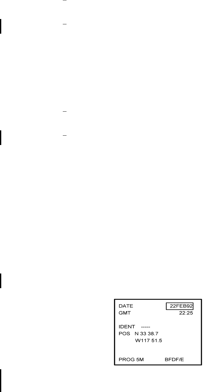
Global
AIRBORNE FLIGHT INFORMATION SYSTEM
IMAFISJWA 4-111
March/2001
1Pin designation for + 28 VDC on DMU PN 42000-XX-XX is J1-5, J1-3 with a
return on J1-4.
2Pin designation for + 28 VDC on DMU PN 400-045500-XXXX is J2-6, J2-7
with a return on J2-1 and J2-2.
3. If the message AFIS LINK FAIL appears on the GNS-X Message Page:
(a) Check aircraft wiring connection between the NMU and DMU and between the
CDU and DMU (+ 28 VDC Switched On Power Control) per Section 3.
(b) Verify that the + 28 VDC is present on the DMU at the appropriate pin locations
as defined in Section 3.
1Pin designation for + 28 VDC on DMU PN 42000-XX-XX is J1-5, J1-3 with a
return on J1-4.
2Pin designation for + 28 VDC on DMU PN 400-045500-XXXX is J2-6, J2-7
with a return on J2-1 and J2-2.
4. If the message AFIS CONFIG CHG is displayed, verify that the AFIS configuration
module is programmed per Section 4, AFIS CONFIGURATION.
5. If the message AFIS CONFIG FAIL is displayed, check wiring connection between
the Configuration Module and the DMU.
6. If the message AFIS CONFIG LOST is displayed, check wiring connection between
the Configuration Module and the DMU.
D. If no AFIS failure messages appear, release MSG Key and CRT will display the
Initialization Page. See Figure 4-250 or Figure 4-251
GNS-1000 OR GNS-X
INITIALIZATION PAGE
Figure 4-250

Global
AIRBORNE FLIGHT INFORMATION SYSTEM
IMAFISJWA 4-112
March/2001
GNS-1000 OR GNS-X
INITIALIZATION PAGE
Figure 4-251
E. With cursor positioned over the DATE field, perform the following:
1. To accept DATE display, press ENTER key.
2. To enter new date make numerical entry from keyboard in order of day-month-year
and press ENTER key.
NOTE:
For example, 5 Feb 1992 would be entered as 050292. Errors in fields
may be corrected as follows: If incorrect digit is entered in a field with
cursor still over the field the BACK key may be used to erase the digit.
To correct the field after the field has been entered or to enter a new
date use the ⇓ key to position cursor over field and enter the new date.
F. Observe that the cursor is over the GMT field after the date was entered. If GMT is
correct, press ENTER. If the GMT requires updating, update GMT in the order of hours
then minutes and press ENTER.
G. Present Position Entry Procedure
1. Observe that the cursor is over the IDENT field. Enter IDENT or accept existing
IDENT and press ENTER.
2. If system does not recognize the entered IDENT, the Waypoint page should appear.
3. Insert present position coordinates or accept existing coordinates by placing cursor
over the coordinates indicated and press ENTER. AFIS Flight Plan List Page
appears. See Figure 4-252.
H. Verify that the AFIS Flight Plan List Page displays the programmed Flight Plan.
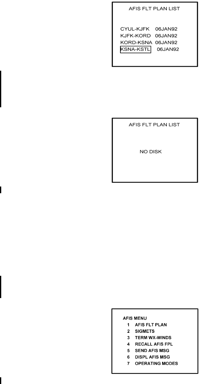
Global
AIRBORNE FLIGHT INFORMATION SYSTEM
IMAFISJWA 4-113
March/2001
Figure 4-252
1. If the NO DISK message appears, verify that the pre-programmed AFIS disk is in the
DTU. If the message persists, check wiring between the DMU and DTU per Section
3. See Figure 4-253.
Figure 4-253
I. SEND MESSAGE Test Procedure for AFIS Users NOT EQUIPPED with Satellite Data
Communications System (System Functional Test)
NOTE:
Aircraft must be in range of ARINC/ACARS or SITA Aircomm, or ground
station and the appropriate ground network must be enabled for
message to be sent to and received from the Global Data Center.
1. Press the DATA key on the GNS-500A or the PLAN key or AFIS key on the
GNS-1000 or GNS-X until the AFIS MENU Page appears. See Figures 4-254
through 4-256.
Figure 4-254
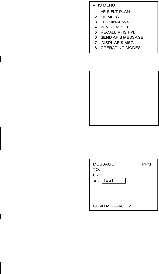
Global
AIRBORNE FLIGHT INFORMATION SYSTEM
IMAFISJWA 4-114
March/2001
Figure 4-255
Figure 4-256
2. Position Cursor over option, SEND AFIS MSG, and press ENTER. MESSAGE page
is displayed. See Figure 4-257.
Figure 4-257
3. Position Cursor over the # field and insert the word TEST.
4. Press ENTER until cursor is over SEND MESSAGE? field.
5. Press ENTER to send the TEST message.
6. When MSG annunciator blinks, press MSG key. SEE AFIS MSG appears on the
System Message Page. See Figure 4-258 or Figure 4-259.
NOTE:
If ARINC/ACARS or SITA Aircomm, or ground station is not within
receiving range, the message NO COMM is displayed on the message
page.
AFIS MENU
1. WX GRAPHICS
2. TERMINAL WX
3. SIGMETS
4. WINDS ALOFT
5. AFIS FLT PLAN
6. RECALL AFIS FPL
7. SEND AFIS MESSAGE
8. DISPL AFIS MSG
9. OPERATING MODES
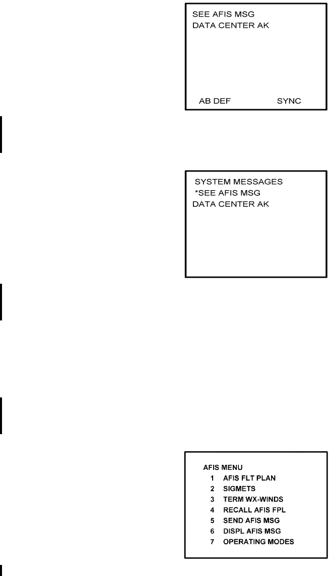
Global
AIRBORNE FLIGHT INFORMATION SYSTEM
IMAFISJWA 4-115
March/2001
For Aircraft equipped with the Antenna Switching Unit, if DATA LINK
DISABLED message appears, enable the AFIS air to ground data link.
GNS-500A
SYSTEM MESSAGE PAGE
Figure 4-258
GNS-1000 OR GNS-X
SYSTEM MESSAGE PAGE
Figure 4-259
7. Press DATA key on the GNS-500A or Plan key or AFIS key on the GNS-1000 or
GNS-X until the AFIS MENU page appears.
8. Position Cursor over option, DISPL AFIS MSG (see Figures 4-260 through 4-262)
and press ENTER. AFIS MESSAGE page is displayed with message from Global
Data Center. See Figure 4-263.
Figure 4-260
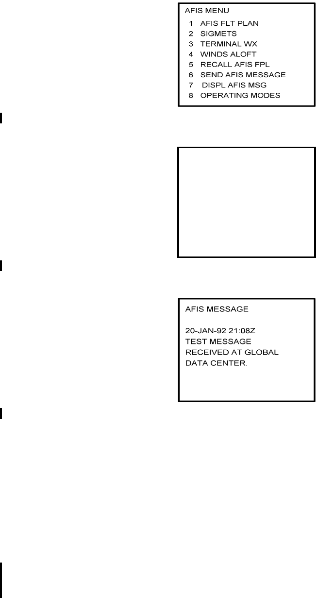
Global
AIRBORNE FLIGHT INFORMATION SYSTEM
IMAFISJWA 4-116
March/2001
Figure 4-261
Figure 4-262
Figure 4-263
J. SEND MESSAGE Test Procedure for AFIS Users EQUIPPED with Satellite Data
Communication System (System Functional Test).
1. Using VHF Network to Send Test Message
NOTE:
Aircraft must be in range of ARINC/ACARS or SITA Aircomm, or ground
station and the appropriate ground network must be enabled for message
to be sent to and received from the Global Data Center.
(a) Press the DATA key on the GNS-500A or the PLAN key or AFIS key on the
GNS-1000 or GNS-X until the AFIS MENU page appears. See Figures 4-264
through 4-266.
AFIS MENU
1. WX GRAPHICS
2. TERMINAL WX
3. SIGMETS
4. WINDS ALOFT
5. AFIS FLT PLAN
6. RECALL AFIS FPL
7. SEND AFIS MESSAGE
8. DISPL AFIS MSG
9. OPERATING MODES
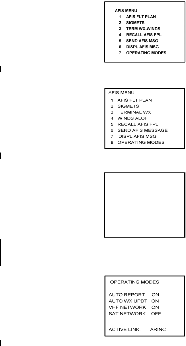
Global
AIRBORNE FLIGHT INFORMATION SYSTEM
IMAFISJWA 4-117
March/2001
Figure 4-264
Figure 4-265
Figure 4-266
(b) Position Cursor over option, OPERATING MODES, and press ENTER.
OPERATING MODES page is displayed. See Figure 4-267.
Figure 4-267
AFIS MENU
1. WX GRAPHICS
2. TERMINAL WX
3. SIGMETS
4. WINDS ALOFT
5. AFIS FLT PLAN
6. RECALL AFIS FPL
7. SEND AFIS MESSAGE
8. DISPL AFIS MSG
9. OPERATING MODES
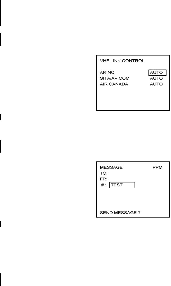
Global
AIRBORNE FLIGHT INFORMATION SYSTEM
IMAFISJWA 4-118
March/2001
(c) Verify VHF NETWORK is ON and SAT NETWORK is OFF or perform the
following:
To turn VHF NETWORK on, position cursor over OFF option of VHF network
field, press BACK key and then press ENTER key to turn on. Figure 4-268, VHF
LINK CONTROL page appears. Depress ENTER until cursor is off the page and
OPERATING MODES page is displayed.
To turn SAT NETWORK off, position cursor over ON option of SAT network field,
press BACK key and then press ENTER key to turn off. See Figure 4-267.
Figure 4-268
(d) Press BACK key to return to AFIS MENU page.
(e) Position cursor over option, SEND AFIS MSG, and press ENTER. MESSAGE
page is displayed. See Figure 4-269.
Figure 4-269
(f) Position cursor over the # field and insert the word TEST.
(g) Press ENTER until cursor is over SEND MESSAGE? field.
(h) Press ENTER to send the TEST message.
(i) When MSG annunciator blinks, press MSG key. SEE AFIS MSG appears on the
System Message Page. See Figure 4-270 or Figure 4-271.
NOTE:
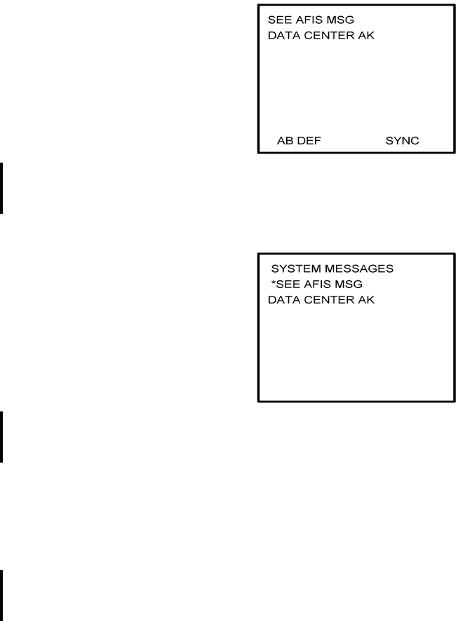
Global
AIRBORNE FLIGHT INFORMATION SYSTEM
IMAFISJWA 4-119
March/2001
If ARINC/ACARS or SITA Aircomm, or ground station is not within
receiving range, the message NO COMM is displayed on the message
page
For Aircraft equipped with the Antenna Switching Unit, if DATA LINK
DISABLED message appears, enable the AFIS air to ground data link.
GNS-500A
SYSTEM MESSAGE PAGE
Figure 4-270
GNS-1000 OR GNS-X
SYSTEM MESSAGE PAGE
Figure 4-271
(j) Press DATA key on the GNS-500A or PLAN key or AFIS key on the GNS-1000
or GNS-X until AFIS MENU page appears.
(k) Position cursor over option, DISPL AFIS MSG (see Figure 4-272 through 4-274)
and press ENTER. AFIS MESSAGE page is displayed with message from Global
Data Center. See Figure 4-275.
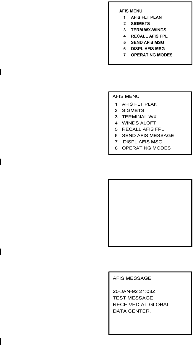
Global
AIRBORNE FLIGHT INFORMATION SYSTEM
IMAFISJWA 4-120
March/2001
Figure 4-272
Figure 4-273
Figure 4-274
Figure 4-275
2. Using Satellite Network to Send Test Message
AFIS MENU
1. WX GRAPHICS
2. TERMINAL WX
3. SIGMETS
4. WINDS ALOFT
5. AFIS FLT PLAN
6. RECALL AFIS FPL
7. SEND AFIS MESSAGE
8. DISPL AFIS MSG
9. OPERATING MODES
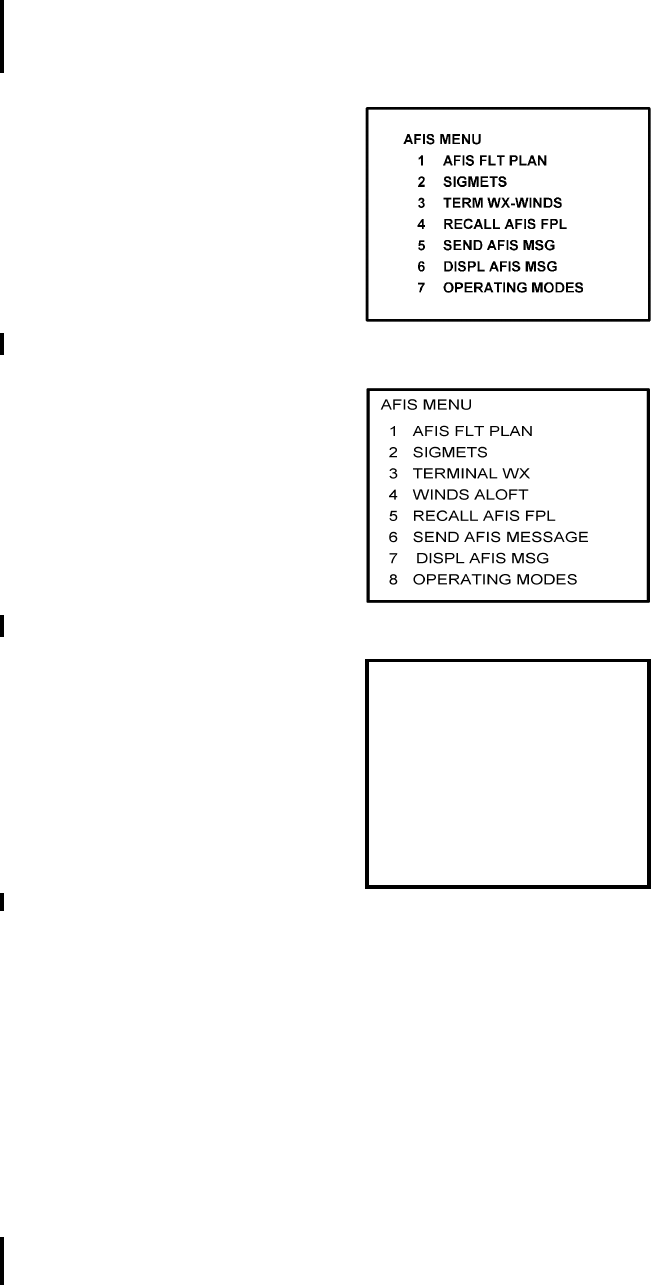
Global
AIRBORNE FLIGHT INFORMATION SYSTEM
IMAFISJWA 4-121
March/2001
(a) Press the DATA key on the GNS-500A or the PLAN key or AFIS key on the
GNS-1000 or GNS-X, XL, XES or XLS until the AFIS MENU page appears. See
Figures 4-276 through 4-278.
Figure 4-276
Figure 4-277
Figure 4-278
(b) Position cursor over option, OPERATING MODES, and press ENTER.
OPERATING MODES page is displayed. See Figure 4-279.
AFIS MENU
1. WX GRAPHICS
2. TERMINAL WX
3. SIGMETS
4. WINDS ALOFT
5. AFIS FLT PLAN
6. RECALL AFIS FPL
7. SEND AFIS MESSAGE
8. DISPL AFIS MSG
9. OPERATING MODES
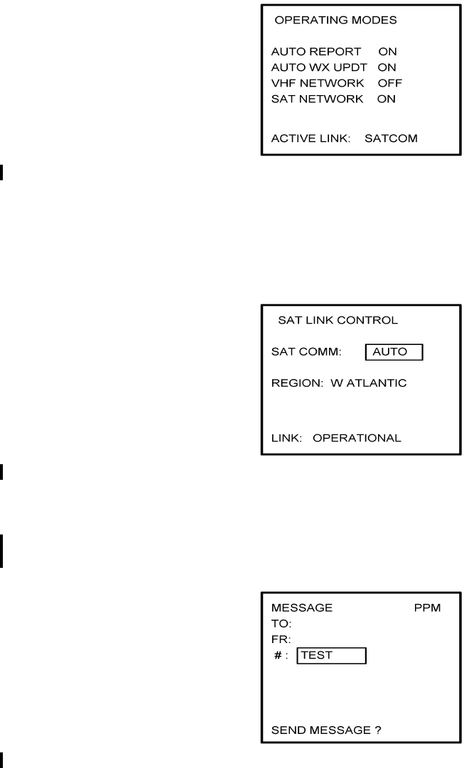
Global
AIRBORNE FLIGHT INFORMATION SYSTEM
IMAFISJWA 4-122
March/2001
Figure 4-279
NOTE:
This page will not appear if the system is configured for ARINC 741 or
SATFONE systems.
Figure 4-280
(d) Press BACK key to return to AFIS MENU page.
(e) Position cursor over option, SEND AFIS MSG, and press ENTER. MESSAGE
page is displayed. See Figure 4-281.
Figure 4-281
(f) Position cursor over the # field and insert the word TEST.
(g) Press ENTER until cursor is over SEND MESSAGE? field.
(h) Press ENTER to send the TEST message.
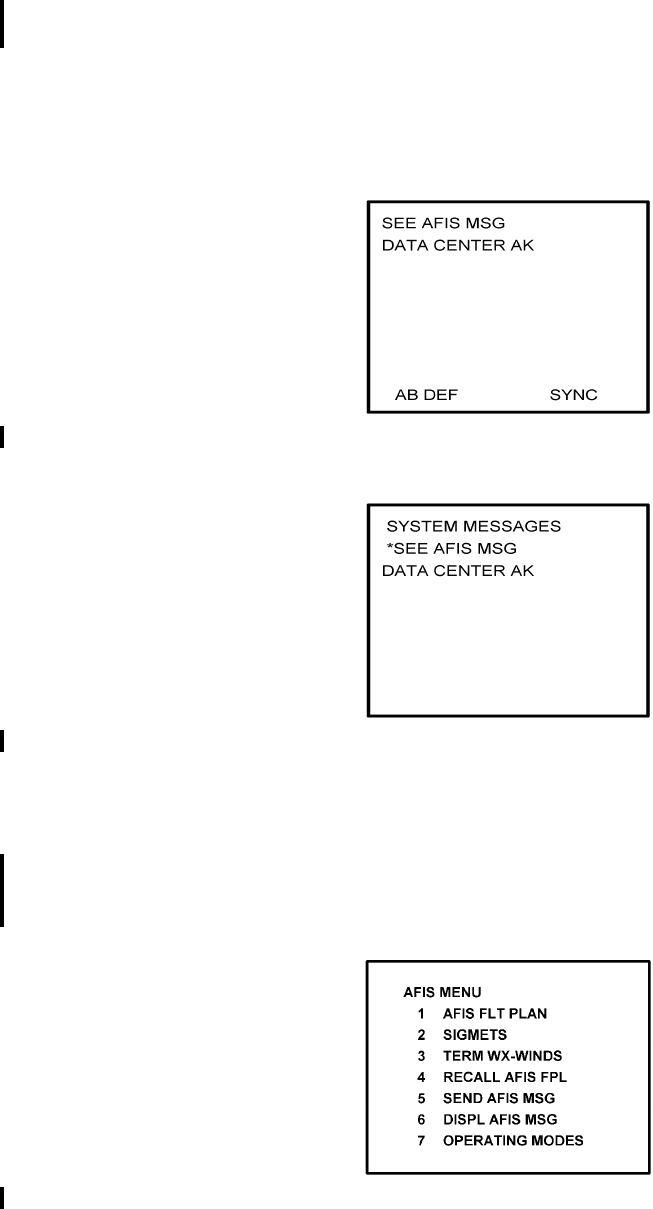
Global
AIRBORNE FLIGHT INFORMATION SYSTEM
IMAFISJWA 4-123
March/2001
(i) When MSG annunciator blinks, press MSG key. SEE AFIS MSG appears on the
System Message Page. See Figure 4-282 or Figure 4-283.
NOTE:
If unable to communicate through satellite network, the message NO
COMM is displayed on the message page.
Figure 4-282
Figure 4-283
(j) Press DATA key on the GNS-500A or PLAN key or AFIS key on the GNS-1000
or GNS-X until AFIS MENU page appears.
(k) Position cursor over option, DISPL AFIS MSG (see Figures 4-284 through 4-286)
and press ENTER. AFIS MESSAGE page is displayed with message from Global
Data Center. See Figure 4-287.
Figure 4-284
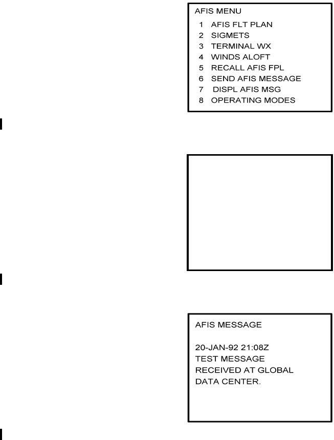
Global
AIRBORNE FLIGHT INFORMATION SYSTEM
IMAFISJWA 4-124
March/2001
Figure 4-285
Figure 4-286
Figure 4-287
K. Fuel Flow Test
NOTE:
Fuel flow is a customer specified AFIS option for GNS-500A users with
DMU P/N 42000-02-02, P/N 42000-04-03, P/N 400-045500-0002, P/N
400-045500-0004 or P/N 400-045500-0006. Since automatic fuel flow
from the DMU to the GNS-500A is an advisory feature, it is
recommended that the system fuel flow be checked against the
aircraft’s primary fuel flow gauges. The data should not replace the
aircraft’s primary fuel flow and quantity gauges.
1. Start aircraft engines.
AFIS MENU
1. WX GRAPHICS
2. TERMINAL WX
3. SIGMETS
4. WINDS ALOFT
5. AFIS FLT PLAN
6. RECALL AFIS FPL
7. SEND AFIS MESSAGE
8. DISPL AFIS MSG
9. OPERATING MODES

Global
AIRBORNE FLIGHT INFORMATION SYSTEM
IMAFISJWA 4-125
March/2001
2. Press NAV key on GNS-500A until the Flight Plan Progress Page appears. See
Figure 4-288.
Figure 4-288
3. Compare actual field (A) for Fuel Flow Per Engine with value displays on panel
indicators. The Fuel Flow Per Engine is an average value and will display a
reasonable comparison to aircraft fuel flow indicators.
4. If Actual field is blank or value is unreasonable, check configuration module for
proper programming.
5. Correct if necessary and repeat test.
(a) If configuration module is OK, check aircraft wiring between fuel indicator and
DMU.
(b) If tracking is not consistent, check aircraft wiring per Section 3.
L. Graphical Weather Test
The Graphical Weather test has been deleted. The AFIS DMU does not control the
software for these pages. If for some reason these pages changed, this manual would
also be revised.
These pages can be found in the Pilots Guide for the GNS-XLS, Enhanced.
Global
AIRBORNE FLIGHT INFORMATION SYSTEM
IMAFISJWA 4-126
March/2001
THIS PAGE IS RESERVED
Global
AIRBORNE FLIGHT INFORMATION SYSTEM
IMAFISJWA EA-1
March/2001
ENVIRONMENTAL QUALIFICATION
APPENDIX
Global
AIRBORNE FLIGHT INFORMATION SYSTEM
IMAFISJWA EA-2
March/2001
THIS PAGE IS RESERVED

Global
AIRBORNE FLIGHT INFORMATION SYSTEM
IMAFISJWA EA-3
March/2001

Global
AIRBORNE FLIGHT INFORMATION SYSTEM
IMAFISJWA EA-4
March/2001

Global
AIRBORNE FLIGHT INFORMATION SYSTEM
IMAFISJWA EA-5
March/2001
Global
AIRBORNE FLIGHT INFORMATION SYSTEM
IMAFISJWA EA-6
March/2001
THIS PAGE IS RESERVED
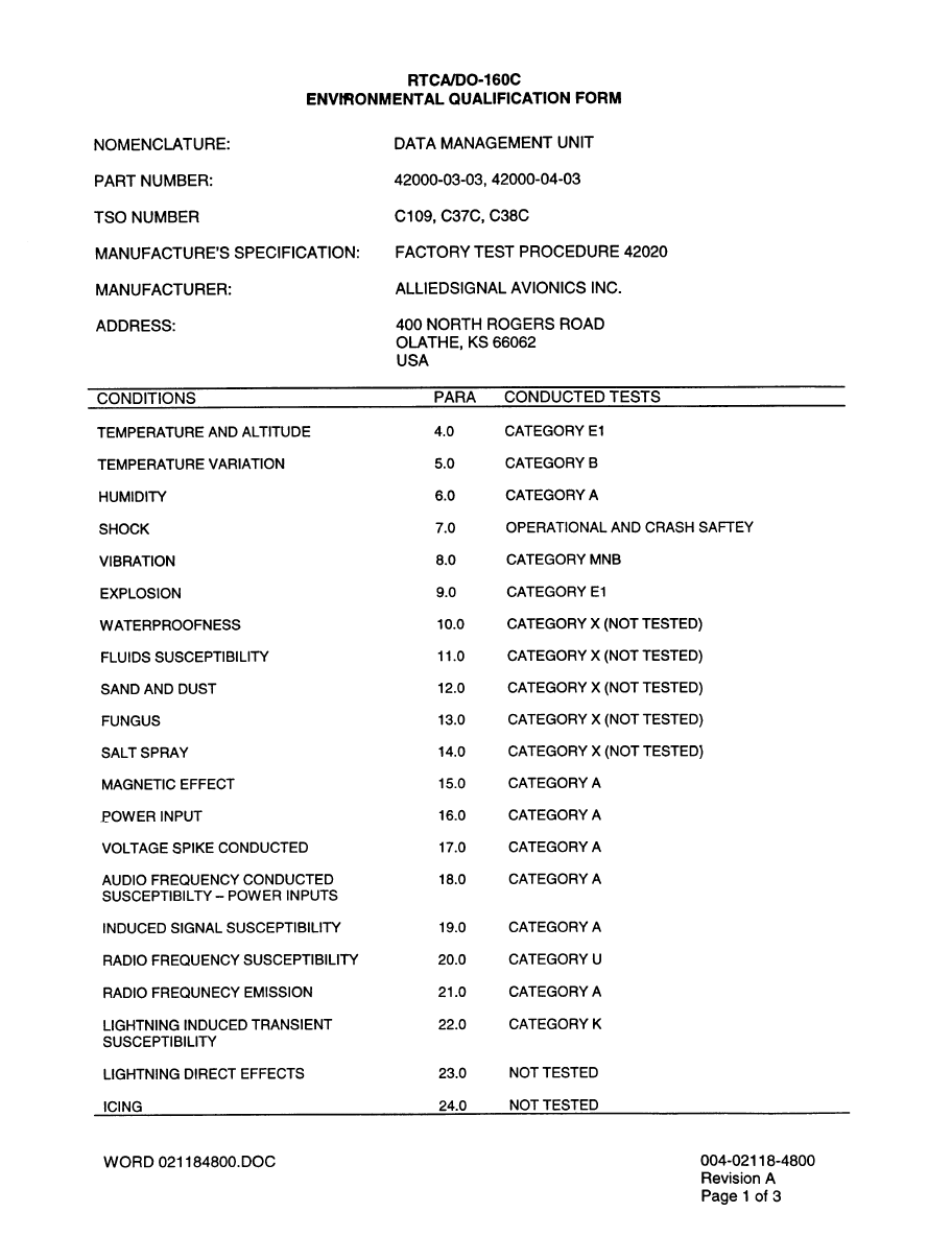
Global
AIRBORNE FLIGHT INFORMATION SYSTEM
IMAFISJWA EA-7
March/2001

Global
AIRBORNE FLIGHT INFORMATION SYSTEM
IMAFISJWA EA-8
March/2001

Global
AIRBORNE FLIGHT INFORMATION SYSTEM
IMAFISJWA EA-9
March/2001
Global
AIRBORNE FLIGHT INFORMATION SYSTEM
IMAFISJWA EA-10
March/2001
THIS PAGE IS RESERVED
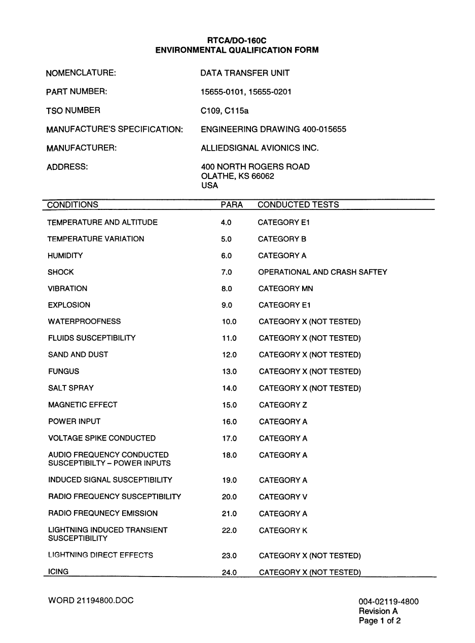
Global
AIRBORNE FLIGHT INFORMATION SYSTEM
IMAFISJWA EA-11
March/2001

Global
AIRBORNE FLIGHT INFORMATION SYSTEM
IMAFISJWA EA-12
March/2001
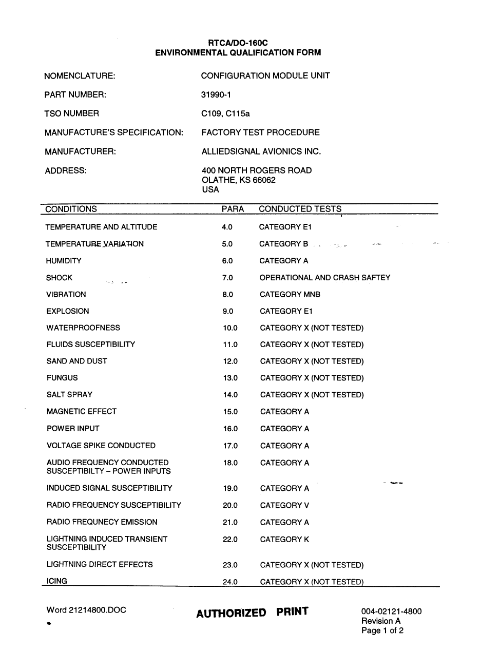
Global
AIRBORNE FLIGHT INFORMATION SYSTEM
IMAFISJWA EA-13
March/2001
Global
AIRBORNE FLIGHT INFORMATION SYSTEM
IMAFISJWA EA-14
March/2001

Global
AIRBORNE FLIGHT INFORMATION SYSTEM
IMAFISJWA EA-15
March/2001
TSO’D UNITS
WITHOUT INDIVIDUAL ENVIRONMENTAL QUALIFICATION FORMS
Part Number Unit Description TSO Categories DO-160B Environmental Categories
44000-1 ASU C109 E1E1 A MNO E1 XXXXX AAAAA
42000-01-01 AFIS DMU C37c, C38c, C109c E1E1 A MNO E1 XXXXX AAAAA
42000-02-02 AFIS DMU C37c, C38c, C109c E1E1 A MNO E1 XXXXX AAAAA
Global
AIRBORNE FLIGHT INFORMATION SYSTEM
IMAFISJWA EA-16
March/2001
THIS PAGE IS RESERVED