Honeywell SD-720 Satellite Data Unit for MCS-7200 SATCOM System User Manual SDIM Multi Channel SATCOM System A15 5111 010
Honeywell International Inc. Satellite Data Unit for MCS-7200 SATCOM System SDIM Multi Channel SATCOM System A15 5111 010
Contents
- 1. SD-720 Manual Part1
- 2. SD-720 Manual Part2
- 3. SD-720 Manual Part 3
- 4. SD-720 Manual Part4
SD-720 Manual Part 3

SYSTEM DESCRIPTION, INSTALLATION, AND MAINTENANCE MANUAL
MCS-4200/7200
TEMPORARY REVISION NO. 23-1
23-20-35 Page 44 of 53
28 Sep 2009
© Honeywell International Inc. Do not copy without express permission of Honeywell.
INSERT PAGE 44 OF 53 FACING PAGE 6-100.
Reason: To add a new failure code, 0B, to Table 6-19 between failure codes 0A and 0D.
Failure code 0B is added as follows:
Table 6-19. Airbus Level I (SDU No. 1) Failure Messages and ATA No.
Failure
Code SDU/SDU No. 1 – CFDS Normal and Interactive Modes ATA Number
0B HDM 232832
SYSTEM DESCRIPTION, INSTALLATION, AND MAINTENANCE MANUAL
MCS--4200/7200 Multi--Channel SATCOM System
23--20--35 15 Jul 2006
Honeywell International Inc. Do not copy without express permission of Honeywell.
Page 6--101
Table 6-19. Airbus Level I (SDU No. 1) Failure Messages and ATA No. (cont)
Failure
Code ATA NumberSDU/SDU No. 1 -- CFDS Normal and Interactive Modes
1A ANTENNA1(116RV1)
HI GAIN ANTENNA--TOP(16RV1)
HI GAIN ANTENNA--L(17RV)
[IGA]
[Top Mount]
[Conformal]
232813
232813
232812
1C HI GAIN ANTENNA--R(18RV) [Conformal] 232812
1F LO GAIN ANTENNA(13RV) 232811
21 MCDU1(2CA1) [A330/A340] 228212
MCDU1(3CA1) [A320] 228212
22 MCDU2(2CA2) [A330/A340] 228212
MCDU2(3CA2) [A320] 228212
23 MCDU3(2CA3) [A330/A340] 228212
MCDU3(3CA3) [A320] 228212
33 ATSU1(1TX1) [ATSU] 462134
ACARS MU(1RB) [A320 ACARS] 232434
ACARS MU1(1RB1) [A330/A340 ACARS] 232434
34 ATSU2 (1TX2) [ATSU] 462134
ACARS MU2 [A320 ACARS] 232434
ACARS MU2(1RB2) [A330/A340 ACARS] 232434
35 ADIRU1(1FP1) 341234
36 ADIRU2(1FP2) 341234
37 RESERVED N/A
38 RESERVED N/A
39 RESERVED N/A
3D FMGC1(1CA1)
FMGEC1(1CA1)
[A320]
[A330/A340]
228334
228334
3E FMGC2(1CA2)
FMGEC2(1CA2)
[A320]
[A330/A340]
228334
228334
40 ARINC 429 ICAO N/A

SYSTEM DESCRIPTION, INSTALLATION, AND MAINTENANCE MANUAL
MCS--4200/7200 Multi--Channel SATCOM System
23--20--35 15 Jul 2006
Honeywell International Inc. Do not copy without express permission of Honeywell.
Page 6--102
Table 6-19. Airbus Level I (SDU No. 1) Failure Messages and ATA No. (cont)
Failure
Code ATA NumberSDU/SDU No. 1 -- CFDS Normal and Interactive Modes
42 CTU--CU CEPT--E1 BUS/SDU1 (105RV1)
CTU--CU CEPT--E1 BUS/SDU1 (105RV1)
CTU--CU CEPT--E1 BUS/SDU1 (5RV1)
CTU--CU CEPT--E1 BUS/SDU1 (5RV1)
[IGA A320]
[IGA A330/A340]
[HGA A320]
[HGA A330/A340]
233500
239200
233500
239200
43 IFE 429 BUS/SDU1 (5RV1)
IFE 429 BUS/SDU1 (105RV1)
IFE 429 BUS/SDU1 (105RV1)
IFE 429 BUS/SDU1 (5RV1)
[A330/A340 HGA]
[A330/A340 HGA]
[A320 IGA]
[A320 HGA]
233000
233000
50 HSDU1 (63RV1)/SDU1 (5RV1) 232839
52 IFE 429 BUS/SDU1 (5RV1)
IFE 429 BUS/SDU1 (105RV1)
IFE 429 BUS/SDU1 (105RV1)
IFE 429 BUS/SDU1 (5RV1)
[A330/A340 HGA]
[A330/A340 HGA]
[A320 IGA]
[A320 HGA]
233000
233000
53 ATSU1 (1TX1)/SDU1(105RV1) [IGA ATSU] 462134
ATSU1 (1TX1)/SDU1(5RV1) [HGA ATSU] 462134
ACARS MU (1RB)/SDU1(105RV1) [IGA A320 ACARS] 232434
ACARS MU1 (1RB1)/SDU1(105RV1) [IGA A330/A340 ACARS] 232434
ACARS MU (1RB)/SDU1(5RV1) [HGA A320 ACARS] 232434
ACARS MU1 (1RB1)/SDU1(5RV1) [HGA A330/A340 ACARS] 232434
54 CTU--CU CEPT--E1 BUS/SDU1(105RV1) [IGA A320] 233500
CTU--CU CEPT--E1 BUS/SDU1(105RV1) [IGA A330/A340] 239200
CTU--CU CEPT--E1 BUS/SDU1(5RV1) [HGA A320] 233500
CTU--CU CEPT--E1 BUS/SDU1(5RV1) [HGA A330/A340] 239200
55 MCDU1(2CA1)/SDU1(105RV1)
MCDU1(2CA1)/SDU1(5RV1)
MCDU1(3CA1)/SDU1(105RV1)
MCDU(3CA1)/SDU1(5RV1)
[IGA A330/A340]
[HGA A330/A340]
[IGA A320]
[HGA A320]
228212
228212
228212
228212
56 MCDU2(2CA2)/SDU1(105RV1)
MCDU2(2CA2)/SDU1(5RV1)
MCDU2(3CA2)/SDU1(105RV1)
MCDU2(3CA2)/SDU1(5RV1)
[IGA A330/A340]
[HGA A330/A340]
IGA A320
HGA A320
228212
228212
228212
228212

SYSTEM DESCRIPTION, INSTALLATION, AND MAINTENANCE MANUAL
MCS--4200/7200 Multi--Channel SATCOM System
23--20--35 15 Jul 2006
Honeywell International Inc. Do not copy without express permission of Honeywell.
Page 6--103
Table 6-19. Airbus Level I (SDU No. 1) Failure Messages and ATA No. (cont)
Failure
Code ATA NumberSDU/SDU No. 1 -- CFDS Normal and Interactive Modes
57 ATSU2 (1TX2)/SDU1(105RV1) [IGA ATSU] 462134
ATSU2 (1TX2)/SDU1(5RV1) [HGA ATSU] 462134
ACARS MU2/SDU1(105RV1) [IGA A320 ACARS] 232434
ACARS MU2 (1RB2)/SDU1(105RV1) [IGA A330/A340 ACARS] 232434
ACARS MU2/SDU1(5RV1) [HGA A320 ACARS] 232434
ACARS MU2 (1RB2)/SDU1(5RV1) [HGA A330/A340 ACARS] 232434
59 CFDIU(1TW)/SDU1(105RV1) [IGA A320] 313234
CMC1(1TM1)/SDU1(105RV1) [IGA A330/A340] 451334
CFDIU(1TW)/SDU1(5RV1) [HGA A320] 313234
CMC1(1TM1)/SDU1(5RV1) [HGA A330/A340] 451334
5A ADIRU1(1FP1)/SDU1(105RV1)
ADIRU1(1FP1)/SDU1(5RV1)
[IGA]
[HGA]
341234
341234
5B ADIRU2(1FP2)/SDU1(105RV1)
ADIRU2(1FP2)/SDU1(5RV1)
[IGA]
[HGA]
341234
341234
5C HPA1 (110RV1)/SDU1(105RV1)
HPA--HI GAIN(7RV1)/SDU1(5RV1)
[IGA]
[HGA]
232831
232831
5F HPA--LO GAIN(9RV)/SDU1(5RV1)
HPA--LO GAIN(9RV)/SDU1(105RV1)
[HGA + LGA]
[IGA + LGA]
232835
232835
62 BSU(8RV1)/SDU1(5RV1)
BSU--L(15RV1)/SDU1(5RV1)
[Top Mount]
[Conformal]
232846
232844
64 BSU--R(15RV2)/SDU1(5RV1) [Conformal] 232844
66 MCDU3(2CA3)/SDU1(105RV1)
MCDU3(2CA3)/SDU1(5RV1)
MCDU3(3CA3)/SDU1(105RV1)
MCDU3(CA3)/SDU1(5RV1)
[IGA A330/A340]
[HGA A330/A340]
[IGA A320]
[HGA A320]
228212
228212
228212
228212
67 RESERVED
68 RESERVED
6A RESERVED
6C RESERVED
6D RESERVED
SYSTEM DESCRIPTION, INSTALLATION, AND MAINTENANCE MANUAL
MCS--4200/7200 Multi--Channel SATCOM System
23--20--35 15 Jul 2006
Honeywell International Inc. Do not copy without express permission of Honeywell.
Page 6--104
Table 6-19. Airbus Level I (SDU No. 1) Failure Messages and ATA No. (cont)
Failure
Code ATA NumberSDU/SDU No. 1 -- CFDS Normal and Interactive Modes
6E RESERVED
6F RESERVED
71 SDU2(105RV2)CROSSTALK BUS/SDU1
(105RV1)
SDU2(5RV2)CROSSTALK BUS/SDU1
5RV1)
[IGA]
[HGA]
232834
232834
73 FMGC1(1CA1)/SDU1(105RV1) [IGA A320] 228334
FMGEC1(1CA1)/SDU1(105RV1) [IGA A330/A340] 228334
FMGC1(1CA1)/SDU1(5RV1) [HGA A320] 228334
FMGEC1(1CA1)/SDU1(5RV1) [HGA A330/A340] 228334
74 FMGC2(1CA2)/SDU1(105RV1) [IGA A320] 228334
FMGEC2(1CA2)/SDU1(105RV1) [IGA A330/A340] 228334
FMGC2(1CA2)/SDU1(5RV1) [HGA A320] 228334
FMGEC2(1CA2)/SDU1(5RV1) [HGA A330/A340] 228334
80 RESERVED
82 RESERVED
88 RESERVED
90 SDU1(105RV1) BUS M--CTRL/HPA1(110RV1) [IGA] 232834
SDU1(5RV1) BUS M--CTRL/HPA--HI
GAIN(7RV1)
[HGA] 232834
96 SDU1(5RV1) BUS M--CTRL/HPA--LO
GAIN(9RV)
[HGA+LGA] 232834
SDU1(105RV1) BUS M--CTRL/HPA--LO
GAIN(9RV)
[IGA+LGA] 232834
98 SDU1(5RV1) BUS M--CTRL/BSU(8RV1)
SDU1(5RV1) BUS M--CTRL/BSU--L(15RV1)
[Top Mount]
[Conformal]
232834
232834
9A BSU--R (15RV2) XTALK BUS/BSU--L(15RV1) [Conformal] 232844
9C SDU1(5RV1) BUS M--CTRL/BSU--R(15RV2) [Conformal] 232834
9D BSU--L (15RV1) XTALK BUS/BSU--R(15RV2) [Conformal] 232844
9E SDU1 (5RV1) /HSDU1 (63RV1) 232834
9F Not applicable for package 6.0 and beyond N/A
SYSTEM DESCRIPTION, INSTALLATION, AND MAINTENANCE MANUAL
MCS--4200/7200 Multi--Channel SATCOM System
23--20--35 15 Jul 2006
Honeywell International Inc. Do not copy without express permission of Honeywell.
Page 6--105
Table 6-19. Airbus Level I (SDU No. 1) Failure Messages and ATA No. (cont)
Failure
Code ATA NumberSDU/SDU No. 1 -- CFDS Normal and Interactive Modes
A1 SDU1(105RV1)/MCDU1(2CA1) [IGA] 228212
SDU1(5RV1)/MCDU1(2CA1) [HGA] 228212
A2 SDU1(105RV1).MCDU2(2CA2) [IGA] 228212
SDU1(5RV1)/MCDU2(2CA2) [HGA] 228212
A3 SDU1(105RV1)/MCDU3(2CA3) [IGA] 228212
SDU1(5RV1)/MCDU3(2CA3) [HGA] 228212
A6 ESU(101RF) ETHERNET 1/HSDU1(63RV1) 464131
A7 ESU(101RF) ETHERNET 2/HSDU1(63RV1) 464131
A8 ESU(101RF) ISDN 1/HSDU1(63RV1) 464131
A9 ESU(101RF) ISDN 2/HSDU1(63RV1) 464131
C0 WRG:CONFIG PIN PROG/SDU1(105RV1) [IGA] 232800
WRG:CONFIG PIN PROG/SDU1(5RV1) [HGA] 232800
C1 LGCIU1(5GA1)/LGCIU2(5GA2)/SDU1(105RV1) [IGA] 323171
LGCIU1(5GA1)/LGCIU2(5GA2)/SDU1(5RV1) [HGA] 323171
C2 SDU1(105RV1) SEL--DISABLE
DISCRETE/SDU2(105RV2)
[IGA] 232834
SDU1(5RV1) SEL--DISABLE
DISCRETE/SDU2(5RV2)
[HGA] 232834
C3 WRG:ICAO ADDRESS PIN
PROG/SDU1(105RV1)
[IGA] 232800
WRG:ICAO ADDRESS PIN
PROG/SDU1(5RV1)
[HGA] 232800
C4 HPA1 (110RV1)/VSWR [IGA] 232831
HPA--HI GAIN(7RV1)/VSWR [HGA] 232831
C5 WRG:CONFIG PIN PROG/SDU1(105RV1)
OWNER REQS DB
[IGA] 232800
WRG:CONFIG PIN PROG/SDU1(5RV1)
OWNER REQS DB
[HGA] 232800
C6 HPA--LO GAIN(9RV)/VSWR 232835
C7 HPA(110RV1)/OVER TEMPERATURE [IGA] 232831
HPA--HI GAIN(7RV1)/OVER TEMPERATURE [HGA] 232831

SYSTEM DESCRIPTION, INSTALLATION, AND MAINTENANCE MANUAL
MCS--4200/7200 Multi--Channel SATCOM System
23--20--35 15 Jul 2006
Honeywell International Inc. Do not copy without express permission of Honeywell.
Page 6--106
Table 6-19. Airbus Level I (SDU No. 1) Failure Messages and ATA No. (cont)
Failure
Code ATA NumberSDU/SDU No. 1 -- CFDS Normal and Interactive Modes
C8 SDU1(105RV1)/BAD DATA FROM GROUND
STATION
[IGA] 232834
SDU1(5RV1)/BAD DATA FROM GROUND
EARTH STATION
[HGA] 232834
C9 HPA--LO GAIN(9RV)/OVER TEMPERATURE 232835
CA SDU1(5RV1)CTRL DISCRETE/DLNA--LO
GAIN(14RV)
[HGA+LGA] 232834
SDU1(105RV1)CTRL DISCRETE/DLNA--LO
GAIN(14RV)
[IGA+LGA] 232834
CB WRG:SDI PIN PROG/HPA1(110RV1) [IGA] 232800
WRG:SDI PIN PROG/HPA--HI GAIN(7RV1) [HGA] 232800
CC WRG:SDI PIN PROG/HPA--LO GAIN(9RV) 232800
CD N/A N/A
CE RESERVED
CF N/A N/A
D0 N/A N/A
D1 WRG:SDI PIN PROG/HPA1(110RV1) 232800
WRG:SDI PIN PROG/HPA--HI GAIN(7RV1) 232800
D2 WRG:SDI PIN PROG/HPA--LO GAIN(9RV) 232800
D3 WRG:SDI PIN PROG/BSU(8RV1)
WRG:SDI PIN PROG/BSU--L(15RV1)
[Top Mount]
[Conformal]
232800
232800
D4 WRG:SDI PIN PROG/BSU--R(15RV2) [Conformal] 232800
D5 SDU1(105RV1)/TXCOAX [IGA] 232834
SDU1(5RV1)/TXCOAX [HGA] 232834
D6 SDU1 (105RV1)/TXCOAX [IGA+LGA] 232834
SDU1(5RV1)/TXCOAX [HGA+LGA] 232834
D7 RESERVED
D8 SDU1(105RV1)/RXCOAX
SDU1(5RV1)/RXCOAX
[IGA]
[HGA]
232834
232834
D9 SDU2(5RV1)/RXCOAX 232834
DA SDU1(105RV1)/RXCOAX [IGA+LGA] 232834
SYSTEM DESCRIPTION, INSTALLATION, AND MAINTENANCE MANUAL
MCS--4200/7200 Multi--Channel SATCOM System
23--20--35 15 Jul 2006
Honeywell International Inc. Do not copy without express permission of Honeywell.
Page 6--107
Table 6-19. Airbus Level I (SDU No. 1) Failure Messages and ATA No. (cont)
Failure
Code ATA NumberSDU/SDU No. 1 -- CFDS Normal and Interactive Modes
SDU1(5RV1)/RXCOAX [HGA+LGA] 232834
DB LO GAIN ANTENNA(13RV)
LOG ON FAILURE
232811
DC N/A N/A to Airbus
DD SDU1(105RV1) OWNER REQS DB SECURED
PARTITION
[IGA] 232834
SDU1(5RV1) OWNER REQS DB SECURED
PARTITION
[HGA] 232834
DE SDU1(105RV1) OWNER REQS DB USER
PARTITION
[IGA] 232834
SDU1(5RV1) OWNER REQS DB USER
PARTITION
[HGA] 232834
DF SDU1(105RV1)
LOG ON FAILURE
[IGA] 232834
SDU1(5RV1)
LOG ON FAILURE
[HGA] 232834
E0 RESERVED
E1 SDU1(5RV1) DISCRETE/HSDU1(63RV1) 232834
E2 N/A N/A
E3 N/A N/A to Airbus
E4 SDU1(5RV1)/HSDU1(63RV1) 232834
E5 N/A N/A to Airbus
E6 HSDU1(63RV1)/TXCOAX 232839
E7 N/A N/A
E8 HSDU1(63RV1)/RXCOAX 232839
E9 N/A N/A
EA N/A N/A to Airbus
EB MCDU1(2CA1)+MCDU2(2CA2)+MCDU3(2CA3)
INACTIVE
[RMP only] 228212
EC WRG:CONFIG PIN PROG/HSDU1(63RV1) 232800
ED WRG:CONFIG PIN PROG/HSDU1(63RV1)
SDU ORT
232800
SYSTEM DESCRIPTION, INSTALLATION, AND MAINTENANCE MANUAL
MCS--4200/7200 Multi--Channel SATCOM System
23--20--35 15 Jul 2006
Honeywell International Inc. Do not copy without express permission of Honeywell.
Page 6--108
Table 6-19. Airbus Level I (SDU No. 1) Failure Messages and ATA No. (cont)
Failure
Code ATA NumberSDU/SDU No. 1 -- CFDS Normal and Interactive Modes
EE WRG:FWD ID1 ADDRESS PIN
PROG/HSDU1(63RV1)
232800
FE POWER SUPPLY INTERRUPT 240000
Table 6-20. Airbus Level I (SDU No. 2) Failure Messages and ATA No.
Failure
Code SDU/SDU No. 2 -- CFDS Normal and Interactive Modes ATA Number
01 SDU2(105RV2)
SDU2(5RV2)
[IGA]
[HGA]
232834
232834
02 SDU1(105RV1) INCOMPATIBILITY
SDU1(5RV1) INCOMPATIBILITY
[IGA]
[HGA]
232834
232834
03 HSDU2(63RV2) 232839
04 HPA2(110RV2)
HPA--HI GAIN(7RV2)
[IGA]
[HGA]
232831
232831
07 HPA--LO GAIN(9RV) 232835
0A HI POWER RELAY(21RV) 232842
0D DLNA2 (119RV2)
DLNA--TOP(19RV2)
DLNA--L(20RV3)
[IGA]
[Top Mount]
[Conformal]
232838
232838
232837
0F DLNA--R(20RV4) [Conformal] 232837
10 DLNA--LO GAIN(14RV) 232836
13 BSU(8RV2)
BSU--L(15RV3)
[Top Mount]
[Conformal]
232846
232844
15 BSU--R(15RV4) [Conformal] 232844
1A ANTENNA2(116RV2)
HI GAIN ANTENNA--TOP(16RV1)
HI GAIN ANTENNA--L(17RV)
[IGA]
[Top Mount]
[Conformal]
232813
232813
232812
1C HI GAIN ANTENNA--R(18RV) [Conformal] 232812
1F LO GAIN ANTENNA(13RV) 232811
21 MCDU1(2CA1)
MCDU1(3CA1)
[A330/A340]
[A320]
228212
228212

SYSTEM DESCRIPTION, INSTALLATION, AND MAINTENANCE MANUAL
MCS-4200/7200
TEMPORARY REVISION NO. 23-1
23-20-35 Page 45 of 53
28 Sep 2009
© Honeywell International Inc. Do not copy without express permission of Honeywell.
INSERT PAGE 45 OF 53 FACING PAGE 6-108.
Reason: To add a new failure code, 0B, to Table 6-20 between failure codes 0A and 0D.
Failure code 0B is added as follows:
Table 6-20. Airbus Level I (SDU No. 2) Failure Messages and ATA No.
Failure
Code SDU/SDU No. 2 – CFDS Normal and Interactive Modes ATA Number
0B HDM 232832

SYSTEM DESCRIPTION, INSTALLATION, AND MAINTENANCE MANUAL
MCS--4200/7200 Multi--Channel SATCOM System
23--20--35 15 Jul 2006
Honeywell International Inc. Do not copy without express permission of Honeywell.
Page 6--109
Table 6-20. Airbus Level I (SDU No. 2) Failure Messages and ATA No. (cont)
Failure
Code ATA NumberSDU/SDU No. 2 -- CFDS Normal and Interactive Modes
22 MCDU2(2CA2)
MCDU2(3CA2)
[A330/A340]
[A320]
228212
228212
23 MCDU3(2CA3)
MCDU3(3CA3)
[A330/A340]
[A320]
228212
228212
33 ATSU1(1TX1) [ATSU] 462134
ACARS MU(1RB) [A320 ACARS] 232434
ACARS MU1(1RB1) [A330/A340 ACARS] 232434
34 ATSU2 (1TX2) [ATSU] 462134
ACARS MU(1RB) [A320 ACARS] 232434
ACARS MU2(1RB2) [A320/A340 ACARS] 232434
35 ADIRU1(1FP1) 341234
36 ADIRU2(1FP2) 341234
37 RESERVED N/A
38 RESERVED N/A
39 RESERVED N/A
3D FMGC1(1CA1)
FMGEC1(1CA1)
[A320]
[A330/A340]
228334
228334
3E FMGC2(1CA2)
FMGEC2(1CA2)
[A320]
[A330/A340]
228334
228334
40 ARINC 429 ICAO 232800
42 CTU -- CU CEPT--E1 BUS/SDU2(105RV2)
CTU -- CU CEPT--E1 BUS/SDU2(105RV2)
CTU -- CU CEPT--E1 BUS/SDU2(5RV2)
CTU -- CU CEPT--E1 BUS/SDU2(5RV2)
[IGA A320]
[IGA A330/A340]
[HGA A320]
[HGA A330/A340]
233500
239200
233500
239200
43 IFE 429 BUS/SDU2(5RV2)
IFE 429 BUS/SDU2(105RV2)
IFE 429 BUS/SDU2(105RV2)
IFE 429 BUS/SDU2(5RV2)
[A330/A340 HGA]
[A330/A340 IGA]
[A320 IGA]
[A320 HGA]
233000
233000
50 HSDU2(63RV2)/SDU2(5RV2) 232839
51 RESERVED

SYSTEM DESCRIPTION, INSTALLATION, AND MAINTENANCE MANUAL
MCS--4200/7200 Multi--Channel SATCOM System
23--20--35 15 Jul 2006
Honeywell International Inc. Do not copy without express permission of Honeywell.
Page 6--110
Table 6-20. Airbus Level I (SDU No. 2) Failure Messages and ATA No. (cont)
Failure
Code ATA NumberSDU/SDU No. 2 -- CFDS Normal and Interactive Modes
52 IFE 429 BUS/SDU2(5RV2)
IFE 429 BUS/SDU2(105RV2)
IFE 429 BUS/SDU2(105RV2)
IFE 429 BUS/SDU2(5RV2)
[A330/A340 HGA]
[A330/A340 IGA]
[A320 IGA]
[A320 HGA]
233000
233000
53 ATSU1 (1TX1)/SDU2(105RV2) [IGA ATSU] 462134
ATSU1 (1TX1)/SDU2(5RV2) [HGA ATSU] 462134
ACARS MU(1RB1)/SDU2(105RV2) [IGA ACARS A330/A340] 232434
ACARS MU1(1RB1)/SDU2(5RV2) [HGA ACARS A330/A340] 232434
ACARS MU(1RB)/SDU2(105RV2) [IGA ACARS A320] 232434
ACARS MU1(1RB)/SDU2(5RV2) [HGA ACARS A320] 232434
54 CTU -- CU CEPT--E1 BUS/SDU2(105RV2) [IGA A320] 233500
CTU -- CU CEPT--E1 BUS/SDU2(105RV2) [IGA A330/A340] 239200
CTU -- CU CEPT--E1 BUS/SDU2(5RV2) [HGA A320] 233500
CTU -- CU CEPT--E1 BUS/SDU2(5RV2) [HGA A330/A340] 239200
55 MCDU1(2CA1)/SDU2(105RV2)
MCDU1(2CA1)/SDU2(5RV2)
MCDU1(3CA1)/SDU2(105RV2)
MCDU1(3CA1)/SDU2(5RV2)
[IGA A330/A340]
[HGA A330/A340]
[IGA A320]
[HGA A320]
228212
228212
228212
228212
56 MCDU2(2CA2)/SDU2(105RV2)
MCDU2(2CA2)/SDU2(5RV2)
MCDU2(3CA2)/SDU2(105RV2)
MCDU2(3CA2)/SDU2(5RV2)
[IGA]
[HGA]
[IGA A320]
[HGA A320]
228212
228212
228212
228212
57 ATSU2 (1TX2)/SDU2(105RV2) [IGA ATSU] 462134
ATSU2 (1TX2)/SDU2(5RV2) [HGA ATSU] 462134
ACARS MU2/SDU2(105RV2) [IGA A320 ACARS] 232434
ACARS MU2 (1RB2)/SDU2(105RV2) [IGA A330/A340 ACARS] 232434
ACARS MU2/SDU2(5RV2) [HGA A320 ACARS] 232434
ACARS MU2(1RB2)/SDU2(5RV2) [HGA A330/A340 ACARS] 232434
SYSTEM DESCRIPTION, INSTALLATION, AND MAINTENANCE MANUAL
MCS--4200/7200 Multi--Channel SATCOM System
23--20--35 15 Jul 2006
Honeywell International Inc. Do not copy without express permission of Honeywell.
Page 6--111
Table 6-20. Airbus Level I (SDU No. 2) Failure Messages and ATA No. (cont)
Failure
Code ATA NumberSDU/SDU No. 2 -- CFDS Normal and Interactive Modes
59 CFDIU(1TW)/SDU2(105RV2) [IGA A320] 313234
CMC1(1TM1)/SDU2(105RV2) [IGA A330/A340] 451334
CFDIU(1TW)/SDU2(5RV2) [HGA A320] 313234
CMC1(1TM1)/SDU2(5RV2) [HGA A330/A340] 451334
5A ADIRU1(1FP1)/SDU2(105RV2) [IGA] 341234
ADIRU1(1FP1)/SDU2(5RV2) [HGA] 341234
5B ADIRU2(1FP2)/SDU2(105RV2) [IGA] 341234
ADIRU2(1FP2)/SDU2(5RV2) [HGA] 341234
5C HPA2(110RV2)/SDU2(105RV2) [IGA] 232831
HPA--HI GAIN(7RV2)/SDU2(5RV2) [HGA] 232831
5F HPA--LO GAIN(9RV)/SDU2(5RV2)
HPA--LO GAIN(9RV)/SDU2(105RV2)
HGA+LGA
IGA+LGA
232835
232835
62 BSU(8RV2)/SDU2(5RV2)
BSU--L(15RV3)/SDU2(5RV2)
[Top Mount]
[Conformal]
232846
232844
64 BSU--R(15RV4)/SDU2(5RV2) [Conformal] 232844
66 MCDU3(2CA3)/SDU2(105RV2)
MCDU3(2CA3)/SDU2(5RV2)
MCDU3(3CA3)/SDU2(105RV2)
MCDU3(3CA3)/SDU2(5RV2)
[IGA A330/A340]
[HGA A330/A340]
[IGA A320]
[HGA A320]
228212
228212
228212
228212
67 RESERVED
68 RESERVED
6A RESERVED
6C RESERVED
6D RESERVED
6E RESERVED
6F RESERVED
71 SDU1(105RV1)CROSSTALK
BUS/SDU2(105RV2)
SDU1(5RV1)CROSSTALK BUS/SDU2(5RV2)
[IGA]
[HGA]
232834
232834
SYSTEM DESCRIPTION, INSTALLATION, AND MAINTENANCE MANUAL
MCS--4200/7200 Multi--Channel SATCOM System
23--20--35 15 Jul 2006
Honeywell International Inc. Do not copy without express permission of Honeywell.
Page 6--112
Table 6-20. Airbus Level I (SDU No. 2) Failure Messages and ATA No. (cont)
Failure
Code ATA NumberSDU/SDU No. 2 -- CFDS Normal and Interactive Modes
73 FMGC1(1CA1)/SDU2(105RV2) [IGA A320] 228334
FMGEC1(1CA1)/SDU2(105RV2) [IGA A330/A340] 228334
FMGC1(1CA1)/SDU2(5RV2) [HGA A320] 228334
FMGEC1(1CA1)/SDU2(5RV2) [HGA A330/A340] 228334
74 FMGC2(1CA2)/SDU2(105RV2) [IGA A320] 228334
FMGEC2(1CA2)/SDU2(105RV2) [IGA A330/A340] 228334
FMGC2(1CA2)/SDU2(5RV2) [HGA A320] 228334
FMGEC2(1CA2)/SDU2(5RV2) [HGA A330/A340] 228334
80 RESERVED
82 RESERVED
88 RESERVED
90 SDU2(105RV2) BUS M--CTRL/HPA2(110RV2) [IGA] 232834
SDU2(5RV2) BUS M--CTRL/HPA--HI
GAIN(7RV2)
[HGA] 232834
96 SDU2(5RV2) BUS M--CTRL/HPA--LO
GAIN(9RV)
SDU2(105RV2) BUS M--CTRL/HPA--LO
GAIN(9RV)
HGA+LGA
IGA+LGA
232834
232834
98 SDU2(5RV2) BUS M--CTRL/BSU(8RV2) [Top Mount] 232834
SDU2(5RV2) BUS M--CTRL/BSU--L(15RV3) [Conformal] 232834
9A BSU--R(15RV4) XTALK/BSU--L(15RV3) [Conformal] 232844
9C SDU2(5RV2) BUS M--CTRL/BSU--R(15RV4) [Conformal] 232834
9D BSU--L(15RV3) XTALK BUS/BSU--R(15RV4) [Conformal] 232844
9E SDU2(5RV2)/HSDU2(63RV2) 232834
9F Not applicable for package 6.0 and beyond N/A
A1 SDU2(105RV2)/MCDU1(2CA1)
SDU2(5RV2)/MCDU1(2CA1)
[IGA]
[HGA]
228212
228212
A2 SDU2(105RV2)/MCDU2(2CA2)
SDU2(RV2)/MCDU2(2CA2)
[IGA]
[HGA]
228212
228212

SYSTEM DESCRIPTION, INSTALLATION, AND MAINTENANCE MANUAL
MCS--4200/7200 Multi--Channel SATCOM System
23--20--35 15 Jul 2006
Honeywell International Inc. Do not copy without express permission of Honeywell.
Page 6--113
Table 6-20. Airbus Level I (SDU No. 2) Failure Messages and ATA No. (cont)
Failure
Code ATA NumberSDU/SDU No. 2 -- CFDS Normal and Interactive Modes
A3 SDU2(105RV2)/MCDU3(2CA3)
SDU2(5RV2)/MCDU3(2CA3)
[IGA]
[HGA]
228212
228212
A6 ESU(101RF) ETHERNET 1/HSDU2(63RV2) 464131
A7 ESU(101RF) ETHERNET 2/HSDU2(63RV2) 464131
A8 ESU(101RF) ISDN 1/HSDU2(63RV2) 464131
A9 ESU(101RF) ISDN 2/HSDU2(63RV2) 464131
C0 WRG:CONFIG PIN PROG/SDU2(105RV2)
WRG:CONFIG PIN PROG/SDU2(5RV2)
[IGA]
[HGA]
232800
232800
C1 LGCIU1(5GA1)/LGCIU2(5GA2)/SDU2(105RV2) [IGA] 323171
LGCIU1(5GA1)/LGCIU2(5GA2)/SDU2(5RV2) [HGA] 323171
C2 SDU2(105RV2) SEL--DISABLE
DISCRETE/SDU1(105RV1)
[IGA] 232834
SDU2(5RV2) SELECT--DISABLE
DISCRETE/SDU1(5RV1)
[HGA] 232834
C3 WRG:ICAO ADDRESS PIN PROG/
SDU2(105RV2)
[IGA] 232800
WRG:ICAO ADDRESS PIN PROG/
SDU2(5RV2)
[HGA] 232800
C4 HPA2(110RV2)/COAX [IGA] 232831
HPA--HI GAIN(7RV1)/COAX [HGA] 232831
C5 WRG:CONFIG PIN PROG/SDU2(105RV2)
OWNER REQS DB
[IGA] 232800
WRG:CONFIG PIN PROG/SDU2(5RV2)
OWNER REQS DB
[HGA] 232800
C6 LPA--LO GAIN(9RV)/COAX 232835
C7 HPA2(110RV2)/OVER TEMPERATURE [IGA] 232831
HPA--HI GAIN(7RV2)/OVER TEMPERATURE [HGA] 232831
C8 SDU2(105RV2)/BAD DATA FROM GROUND
STATION
[IGA] 232834
SDU2(5RV2)/BAD DATA FROM GROUND
EARTH STATION
[HGA] 232834
C9 HPA--LO GAIN(9RV)/OVER TEMPERATURE 232835
SYSTEM DESCRIPTION, INSTALLATION, AND MAINTENANCE MANUAL
MCS--4200/7200 Multi--Channel SATCOM System
23--20--35 15 Jul 2006
Honeywell International Inc. Do not copy without express permission of Honeywell.
Page 6--114
Table 6-20. Airbus Level I (SDU No. 2) Failure Messages and ATA No. (cont)
Failure
Code ATA NumberSDU/SDU No. 2 -- CFDS Normal and Interactive Modes
CA SDU2(5RV2)CTRL DISCRETE/DLNA--LO
GAIN(14RV)
SDU2(105RV2)CTRL DISCRETE/DLNA--LO
GAIN(14RV)
[HGA+LGA]
[IGA+LGA]
232834
232834
CB WRG:SDI PIN PROG/HPA2(110RV1) [IGA] 232800
WRG:SDI PIN PROG/HPA--HI GAIN(7RV2) [HGA] 232800
CC WRG:SDI PIN PROG/HPA--LO GAIN(9RV) 232800
CD N/A N/A
CE RESERVED
CF N/A N/A
D0 N/A N/A
D1 WRG:SDI PIN PROG/HPA2(110RV1) [IGA] 232800
WRG:SDI PIN PROG/HPA--HI GAIN(7RV2) [HGA] 232800
D2 WRG:SDI PIN PROG/HPA--LO GAIN(9RV) 232800
D3 WRG:SDI PIN PROG/BSU(8RV2)
WRG:SDI PIN PROG/BSU--L(15RV3)
[Top Mount]
[Conformal]
232800
232800
D4 WRG:SDI PIN PROG/BSU--R(15RV4) [Conformal] 232800
D5 SDU2(105RV2)/TXCOAX [IGA] 232834
SDU2(5RV2)/TXCOAX [HGA] 232834
D6 SDU2(105RV2)/TXCOAX
SDU2(5RV2)/TXCOAX
[LGA]
[HGA or IGA]
232834
232834
D7 RESERVED
D8 SDU2(105RV2)/RXCOAX [IGA] 232834
SDU2(5RV2)/RXCOAX [HGA] 232834
D9 SDU2(5RV2)/RXCOAX [HGA] 232834
DA SDU2(105RV2)/RXCOAX
SDU2(5RV2)/RXCOAX
LGA+(HGA or IGA)
LGA+(HGA or IGA)
232834
232834
DB LO GAIN ANTENNA(13RV) LOG ON FAILURE 232811
DC N/A N/A

SYSTEM DESCRIPTION, INSTALLATION, AND MAINTENANCE MANUAL
MCS--4200/7200 Multi--Channel SATCOM System
23--20--35 15 Jul 2006
Honeywell International Inc. Do not copy without express permission of Honeywell.
Page 6--115
Table 6-20. Airbus Level I (SDU No. 2) Failure Messages and ATA No. (cont)
Failure
Code ATA NumberSDU/SDU No. 2 -- CFDS Normal and Interactive Modes
DD SDU2 (105RV2) OWNER REQS DB SECURED
PARTITION
[IGA] 232834
SDU2 (5RV2) OWNER REQS DB SECURED
PARTITION
[HGA] 232834
DE SDU2 (105RV2) OWNER REQS DB USER
PARTITION
[IGA] 232834
SDU2 (5RV2) OWNER REQS DB USER
PARTITION
[HGA] 232834
DF SDU2 (105RV2) LOG ON FAILURE [IGA] 232834
SDU2 (5RV2) LOG ON FAILURE [HGA] 232834
E0 RESERVED
E1 SDU2(5RV2) DISCRETE/HSDU2(63RV2) 232834
E2 N/A N/A
E3 N/A N/A
E4 SDU2(5RV2)/HSDU2(63RV2) 232834
E5 N/A N/A
E6 HSDU2(63RV2)/TXCOAX 232839
E7 N/A N/A
E8 HSDU2(63RV2)/RXCOAX 232839
E9 N/A N/A
EA N/A N/A
EB MCDU1(2CA1)+MCDU2(2CA2)+MCDU3(2CA3)
INACTIVE
[RMP only] 228212
EC WRG:CONFIG PIN PROG/HSDU2(63RV2) 232800
ED WRG:CONFIG PIN PROG/HSDU2(63RV2)
SDU ORT
232800
EE WRG:FWD ID1 ADDRESS PIN
PROG/HSDU2(63RV2)
232800
FE POWER SUPPLY INTERRUPT 240000

SYSTEM DESCRIPTION, INSTALLATION, AND MAINTENANCE MANUAL
MCS--4200/7200 Multi--Channel SATCOM System
23--20--35 15 Jul 2006
Honeywell International Inc. Do not copy without express permission of Honeywell.
Page 6--116
Table 6-21. McDonnell Douglas Level I Failures Messages and
ATA Reference Numbers
Failure
Code CFDS Normal and Interactive Modes ATA Number
01 SDU 232610
02 OTHER SDU INCOMPATIBILITY 232611
03 HSU 232664
04 HPA--IN GAIN [IGA] 232600
HPA--HI GAIN [HGA] 232613
07 HPA--LO GAIN 232614
0A HI POWER RELAY 232615
0D DLNA--(TOP/L) 232616
0F DLNA--R 232618
10 DLNA--LO GAIN 232619
13 BSU--(TOP/L) 23261B
15 BSU--R 23261C
1A IN GAIN ANTENNA--TOP [IGA] 232600
HI GAIN ANTENNA--(TOP/L) [HGA] 23261D
1C HI GAIN ANTENNA--R 23261F
1F LO GAIN ANTENNA 232620
21 MCDU1 232635
22 MCDU2 232636
23 MCDU3 232637
33 (ACARS MU/CMU) 23243C
34 (ACARS MU/CMU)2 N/A
35 (IRS/ADIRU)--PRI 23263E
36 (IRS/ADIRU)--SEC 23263F
37 RESERVED
38 RESERVED
39 RESERVED
3D (FMC/VIA)1 232642
3E (FMC/VIA)2 232643

SYSTEM DESCRIPTION, INSTALLATION, AND MAINTENANCE MANUAL
MCS-4200/7200
TEMPORARY REVISION NO. 23-1
23-20-35 Page 46 of 53
28 Sep 2009
© Honeywell International Inc. Do not copy without express permission of Honeywell.
INSERT PAGE 46 OF 53 FACING PAGE 6-116.
Reason: To add a new failure code, 0B, to Table 6-21 between failure codes 0A and 0D.
Failure code 0B is added as follows:
Table 6-21. McDonnell Douglas Level I Failure Messages and
ATA Reference Numbers
Failure
Code CFDS Normal and Interactive Modes ATA Number
0B HDM 232664

SYSTEM DESCRIPTION, INSTALLATION, AND MAINTENANCE MANUAL
MCS--4200/7200 Multi--Channel SATCOM System
23--20--35 15 Jul 2006
Honeywell International Inc. Do not copy without express permission of Honeywell.
Page 6--117
Table 6-21. McDonnell Douglas Level I Failures Messages and
ATA Reference Numbers (cont)
Failure
Code ATA NumberCFDS Normal and Interactive Modes
40 ARINC 429 ICAO ADDRESS N/A
42 CTU 232644
43 (CFS/CPDF) TBD
50 HSU/SDU 232664
52 (CFS/CPDF)/SDU TBD
53 (ACARS MU/CMU)/SDU 23263C
54 CTU/SDU 232644
55 MCDU1/SDU 232635
56 MCDU2/SDU 232636
57 (ACARS MU/CMU)2/SDU N/A
59 CFDIU/SDU 232641
5A (IRS/ADIRU)--PRI/SDU 23263E
5B (IRS/ADIRU)--SEC/SDU 23263F
5C HPA--IN GAIN/SDU [IGA] 232600
HPA--HI GAIN/SDU [HGA] 232600
5F HPA--LO GAIN/SDU 232623
62 BSU--(TOP/L)/SDU 232626
64 BSU--R/SDU 232627
66 MCDU3/SDU 232637
67 RESERVED
68 RESERVED
6A RESERVED
6C RESERVED
6D RESERVED
6E RESERVED
6F RESERVED
71 OTHER SDU/THIS SDU 232600
73 (FMC/VIA)1/SDU 232642

SYSTEM DESCRIPTION, INSTALLATION, AND MAINTENANCE MANUAL
MCS--4200/7200 Multi--Channel SATCOM System
23--20--35 15 Jul 2006
Honeywell International Inc. Do not copy without express permission of Honeywell.
Page 6--118
Table 6-21. McDonnell Douglas Level I Failures Messages and
ATA Reference Numbers (cont)
Failure
Code ATA NumberCFDS Normal and Interactive Modes
74 (FMC/VIA)2/SDU 232643
80 RESERVED
82 RESERVED
88 RESERVED
90 SDU M--CTRL/HPA--IN GAIN
SDU M--CTRL/HPA--HI GAIN
[IGA]
[HGA]
232600
232600
96 SDU M--CTRL/HPA--LO GAIN 23262D
98 SDU M--CTRL/BSU--(TOP/L) 232600
9A BSU--R XTALK/BSU--L 232600
9C SDU M--CTRL/BSU--R 232630
9D BSU--L XTALK/BSU--R 232600
9E SDU/HSU 232664
9F RESERVED 232664
A6 HSU ETHERNET PORT 1 232664
A7 HSU ETHERNET PORT 2 232664
A8 HSUISDNPORT1 232664
A9 HSUISDNPORT2 232664
C0 WRG:CONFIG PIN PROG/SDU 232600
C1 SDU WOW MISCOMPARE N/A
C2 SDU/OTHER SDU SELECT--DISABLE DISCRETE 232600
C3 WRG:ICAO ADDRESS PIN PROG/SDU 232631
C4 TX PATH VSWR--IN GAIN
TX PATH VSWR--HI GAIN
[IGA]
[HGA]
232600
232600
C5 WRG:CONFIG PIN PROG/SDU OWNER REQS 232600
C6 TX PATH VSWR--LO GAIN 232600
C7 HPA--IN GAIN/OVER TEMPERATURE
HPA--HI GAIN/OVER TEMPERATURE
[IGA]
[HGA]
232600
23262C
C8 BAD DATA FROM GROUND EARTH STATION None
C9 HPA--LO GAIN/OVER TEMPERATURE 232634

SYSTEM DESCRIPTION, INSTALLATION, AND MAINTENANCE MANUAL
MCS--4200/7200 Multi--Channel SATCOM System
23--20--35 15 Jul 2006
Honeywell International Inc. Do not copy without express permission of Honeywell.
Page 6--119
Table 6-21. McDonnell Douglas Level I Failures Messages and
ATA Reference Numbers (cont)
Failure
Code ATA NumberCFDS Normal and Interactive Modes
CA SDU/DLNA--LO GAIN 232619
CB WRG:SDI PIN PROG/HPA--IN GAIN
WRG:SDI PIN PROG/HPA--HI GAIN
[IGA]
[HGA]
232600
232600
CC WRG:SDI PIN PROG/HPA--LO GAIN 232600
CD SDU (POC/TOTC) DATA RESET None
CE RESERVED
CF HPA--IN GAIN (POC/TOTC) DATA RESET
HPA--HI GAIN (POC/TOTC) DATA RESET
[IGA]
[HGA]
None
None
D0 HPA--LO GAIN (POC/TOTC) None
D1 WRG:SDI PIN PROG/HPA--IN GAIN
WRG:SDI PIN PROG/HPA--HI GAIN
[IGA]
[HGA]
232600
232600
D2 WRG:SDI PIN PROG/HPA--LO GAIN 232600
D3 WRG:SDI PIN PROG/BSU--(TOP/L) 232600
D4 WRG:SDI PIN PROG/BSU--R 232600
D5 SDU COAX/HPA--IN GAIN
SDU COAX/HPA--HI GAIN
[IGA]
[HGA]
232600
232600
D6 SDU COAX/HPA--LO GAIN 232600
D7 RESERVED
D8 DLNA/(SDU)--(TOP/L) 232600
D9 DLNA/(SDU)--R 232600
DA DLNA/(SDU)--LO GAIN 232600
DB LO GAIN SUBSYSTEM 232600
DC NO ACTIVE ACARS MU/CMU 232400
DD SDU OWNER REQS -- SECURED None
DE SDU OWNER REQS -- USER None
DF IN GAIN SUBSYSTEM
HI GAIN SUBSYSTEM
[IGA]
[HGA]
232600
232600
E0 RESERVED
E1 BAD HSU DISABLE DISCRETE 232664

SYSTEM DESCRIPTION, INSTALLATION, AND MAINTENANCE MANUAL
MCS--4200/7200 Multi--Channel SATCOM System
23--20--35 15 Jul 2006
Honeywell International Inc. Do not copy without express permission of Honeywell.
Page 6--120
Table 6-21. McDonnell Douglas Level I Failures Messages and
ATA Reference Numbers (cont)
Failure
Code ATA NumberCFDS Normal and Interactive Modes
E2 RESERVED
E3 RESERVED
E4 HSU/SDU INTERFACE VER INCOMPATIBILITY 232664
E5 RESERVED
E6 HSU/HPA TX RF PATH 232664
E7 RESERVED
E8 DLNA/HSU RX RF PATH 232664
E9 RESERVED
EA RESERVED
EC WRG:CONFIG PIN PROG/HSU 232664
ED WRG:CONFIG PIN PROG/HSU SDU OWNER REQS 232664
EE WRG:FWD ID PIN PROG/HSU 232664
FE POWER SUPPLY INTERRUPT None

SYSTEM DESCRIPTION, INSTALLATION, AND MAINTENANCE MANUAL
MCS--4200/7200 Multi--Channel SATCOM System
23--20--35 15 Jul 2006
Honeywell International Inc. Do not copy without express permission of Honeywell.
Page 6--121
4. SCDU for Dual SATCOM
A. General
(1) The SDU supports SCDU page displays for dual systems. All pages are as specified
in paragraph 2.D. (SCDU pages) with the following exceptions.
B. SATCOM Logical Channels
(1) The SATCOM channels for HEADSET calls in a dual system can be supplied by
several combinations of physical channels within both SDUs. These combinations are
determined by the configuration strap settings for cockpit wiring and ORT items
regarding the use of SDU channel resources (items vi, vii, and xlviii). The display of
channel status and selections as reported on menus MAIN, DIRECTORY, and
CATEGORY-n reflect the logical channel status.
C. SATCOM (Cross-Talk Bus Failed)
(1) The SDU designated as the slave unit in a dual system must receive most of the
system status information from the master over the SDU cross-talk bus. If full
communication is not established, the slave unit cannot receive the necessary data
for the display pages. The default SATCOM MAIN MENU display page THIS UNIT
UNAVAILABLE is displayed in this case.
D. SATCOM
(1) The channel status page reflects the physical channels within the SDU that is
providing the display page.
E. SATCOM Menus
(1) The maintenance menus reflect the maintenance data for the SATCOM system that
is providing the display page.
5. Maintenance Panel Assembly
A. General
(1) The maintenance panel assembly interface diagram (Figure 5-17) supplies remote
monitoring of MCS system operation. The maintenance panel assembly is made up
of two parts: the cabin telecommunications (CTM) panel and the Commissioning and
Maintenance Terminal (CMT) panel. The CTM panel is used for monitoring the cabin
telecommunications equipment. The panel contains six lamps to indicate the
availability of the telephone handsets. A keyed on/off switch arms the system when
the key is turned to the ON position.
(2) The CMT panel is used primarily to debug, detect, isolate software and/or hardware
integration, LRU and system integration, formal testing, and system access approval,
as well as general performance analysis. The CMT data connector supplies an
access port for a commissioning and maintenance terminal that can be a personal
computer, a dumb terminal, or a modem. The SDU interface connector on the panel
supplies a remote access port for testing the SDU. The panel also contains lamps to
indicate the status of the MCS system. These lamps are defined in Table 6-22.

SYSTEM DESCRIPTION, INSTALLATION, AND MAINTENANCE MANUAL
MCS--4200/7200 Multi--Channel SATCOM System
23--20--35 15 Jul 2006
Honeywell International Inc. Do not copy without express permission of Honeywell.
Page 6--122
Table 6-22. Commissioning and Maintenance Terminal Panel Lamps
Lamp Definition
IN USE CH--1 (SDU pin TPH1) This lamp lights to show channel 1 is in use.
IN USE CH--2 (SDU pin TPK1) This lamp lights to show channel 2 is in use.
PILOT VCE NOT AVAIL (SDU pin TP3A) This lamp lights to show no additional voice channels can be
established. This can be because no resources are available, or all available
resources being allocated to existing calls.
LOG OFF (SDU pin TPC3) This lamp lights to show no packet mode data service
capability exists at any data rate; system not logged on.
CABIN VCE NOT AVAIL (SDU pin TPB3) This lamp lights to show no additional channels can be
established for analog or digital cabin voice, or circuit--mode data. This can be
because no resources are available, or all available resources being allocated
to existing calls.
MCS FAIL (SDU pin TPG1) This lamp lights to show a total loss of all SATCOM voice and
data services, and at least one cause can be attributable to the MCS system
LRUs themselves. Replacement of the appropriate LRU (SDU, HPA) is
necessary to restore partial or complete service. It is possible for this indicator
and the MCS inoperable indicator (NON-MCS FAIL) to be active
simultaneously, indicating failure in both the MCS system LRUs and nonsystem
LRUs.
NON-MCS FAIL (SDU pin TPE3) This lamp lights to show total loss of all SATCOM voice and
data services, and at least one cause is attributable to the non-MCS system
LRUs, or interfaces to those LRUs. Replacement of the appropriate non MCS
LRU(s), or correction of the interface failure is necessary to restore partial or
complete service. It is possible for this indicator and the SATCOM fail indicator
(MCS FAIL) to be active simultaneously, indicating failure in both the MCS
system LRUs and the nonsystem LRUs or interfaces.
NO SAT LINK (SDU pin TPJ1) This lamp lights to show no SATCOM voice or data services
are available because of the AES not being successfully logged-on, and the
cause is definitely not due to reported failures (MCS or non-MCS). If there is a
MCS or non-MCS failure, the NO SAT LINK lamp will not light.
HGA FAIL (SDU pin TPD3) This lamp lights to show packet-mode data service capability
exists, but only at the lowest channel rates (600 and 1200 bps). This indicator
is assumed to only be present in high gain antennas installations that have a
low gain antenna backup system. The lamp indicates an HGA failure due to the
reduction from normal high speed capability.

SYSTEM DESCRIPTION, INSTALLATION, AND MAINTENANCE MANUAL
MCS--4200/7200 Multi--Channel SATCOM System
23--20--35 15 Jul 2006
Honeywell International Inc. Do not copy without express permission of Honeywell.
Page 7--1
SECTION 7
MAINTENANCE PRACTICES
1. Overview
A. General
(1) This section supplies instructions for removing, reinstalling, and adjusting each LRU
of the MCS that has been installed by the aircraft manufacturer or completion center.
Where applicable, instructions for replacing lamps, knobs, and set screws are
included. Adjustment information is called out as required.
CAUTION: SHOULD ANY INSTALLATION CRITICAL CASES ARISE WITH THE
REINSTALLATION OF ANY UNIT, YOU MUST COMPLY 100 PERCENT
WITH THE INSTRUCTION.
CAUTION: TO PREVENT DAMAGE TO EQUIPMENT, TURN AIRCRAFT POWER OFF
WHEN REMOVING OR INSTALLING LRUS.
2. Equipment and Materials
A. General
CAUTION: DO NOT USE MATERIALS THAT ARE NOT EQUIVALENT TO
MATERIALS SPECIFIED BY HONEYWELL. MATERIALS NOT
EQUIVALENT CAN CAUSE DAMAGE TO THE EQUIPMENT AND CAN
MAKE THE WARRANTY NOT APPLICABLE.
(1) Maintenance materials identified with a Honeywell Material Number (HMN) are given
in Table 7-1.
(2) No additional special equipment or materials other than those commonly used in the
shop are required to install the units in existing trays and clamps, and to adjust the
system. Do not over tighten mounting screws. Where torque values are not given, it
is acceptable to finger tighten the mounting screws.
Table 7-1. Materials
Item Description Source
HMN 97P5778 RTV silicone, No. 3145,
translucent, per MIL--A--46146,
Group II, Type I military
designation M4614621XTN.
Dow Corning Corp, Midland, MI
(05AJ8)
HMN 98C0978 Sealant, corrosion inhibitive
(MIL--S--81733, Type II--1/2 -- for
extrusion application in the time of
1/2 hour) — Pro--Seal 870B--1/2
Courtaulds Aerospace, Glendale,
CA (83574)
NOTES: NOTES:
1. Equivalent alternatives are permitted for materials in this list.
2. The HMN codes in the list of materials identify the Honeywell Material Number (HMN) given to each material.

SYSTEM DESCRIPTION, INSTALLATION, AND MAINTENANCE MANUAL
MCS--4200/7200 Multi--Channel SATCOM System
23--20--35 15 Jul 2006
Honeywell International Inc. Do not copy without express permission of Honeywell.
Page 7--2
3. Procedure for Antennas
A. General
(1) The following paragraphs describe general information when removing or installing
antennas.
NOTE: For all antennas not supplied by Honeywell, removal and installation should
be done according to installation instructions from the manufacturer.
B. Antenna Weather Protection
(1) Some antennas require gaskets and others have O--rings. When reinstalling
antennas, new gaskets or O--rings should be used.
(2) A weather sealant should be applied around the periphery of the antenna base to
prevent seepage of water and condensation and preclude corrosion. If a sealant or
aerodynamic smoother is used around the periphery of the antenna base, it should
be applied after the antenna has been bolted down. The sealant used should be
nonadhering so the antenna can be removed at a later time, if necessary. Chromatic
tape is recommended.
NOTE: When mounting antennas on a pressurized fuselage, a leveling and sealing
compound like Pro-Seal 870B--1/2 should be used between the entire
mounting surface of the antenna and the fuselage. Use of this compound, in
addition to the installation gasket, compensates for surface irregularities and
voids between the antenna and the fuselage. A mold releasing agent can be
used on the fuselage prior to installation to prevent the leveling compound
from adhering to the fuselage.
(3) To prevent water seepage on top mounted antennas, it can be necessary to apply
Silastic sealant (RTV--3145 or equivalent) to the mounting screw heads.
C. Antenna Hardware
(1) Clean the airframe at the antenna mounting area to remove any foreign material.
(2) Because of the insulation qualities of gaskets and leveling compounds, the mounting
screws are required to supply the electrical bonding between the antennas and the
aircraft (typically 15 milliohms or less is required). The technician doing the
reinstallation must be sure any hardware being reused is clean and free of corrosion.
If in doubt, use new hardware.
(3) Gaskets and O--rings deform during initial installation. While it is possible to reuse
gaskets and O--rings, it is highly recommended new gaskets or O--rings be used.

SYSTEM DESCRIPTION, INSTALLATION, AND MAINTENANCE MANUAL
MCS--4200/7200 Multi--Channel SATCOM System
23--20--35 15 Jul 2006
Honeywell International Inc. Do not copy without express permission of Honeywell.
Page 7--3
D. General Antenna Removal Instructions
NOTE: These procedures apply to all antennas. To prevent damage to the
antennas, do not apply pressure to the plastic housings or pry on plastic
housings.
(1) Pull the appropriate circuit breakers.
(2) After removing and saving the hardware, cut the bond line of any installer--applied
sealant between the antenna and the aircraft skin.
(3) Pull the antenna away from the aircraft skin far enough to disconnect the cable
connector(s).
4. Procedure for the LRUs
CAUTION: BEFORE AN LRU IS INSTALLED OR REMOVED, PULL THE CIRCUIT
BREAKERS THAT SUPPLY POWER TO THE LRU TO REMOVE POWER.
CAUTION: MOISTURE AND DIRT CAUSE DAMAGE TO LRUs.
CAUTION: LRU FAILURE RATES INCREASE WITH A RISE IN TEMPERATURE. INSTALL
THE LRUs WITH CLEARANCE; LET THE AIR FLOW ON TOP AND BOTTOM
OF LRUS TO PREVENT OVERHEATING.
A. LRU Removal
(1) Remove an LRU as follows:
(a) Disconnect the circuit breakers that supply power to the LRU.
(b) Tag the circuit breakers with DO-NOT-OPERATE identifiers.
(c) Loosen the clamp knobs and let them drop out of the way.
(d) Pull the LRU forward a minimum of 1/2 inch to clear the rear connector pins.
(e) Lift the LRU free of the cooling air-duct gasket on the mounting rack.
B. LRU Installation
(1) Install an LRU as follows:
(a) Determine the location of each LRU in the aircraft.
(b) Check the LRU to be installed and make sure all connector pins are straight and
ready for connection.
(c) Make sure the index pin coding on the rear connector is correct for the mating
connector.

SYSTEM DESCRIPTION, INSTALLATION, AND MAINTENANCE MANUAL
MCS--4200/7200 Multi--Channel SATCOM System
23--20--35 15 Jul 2006
Honeywell International Inc. Do not copy without express permission of Honeywell.
Page 7--4
(d) Place the LRU in the appropriate mounting rack and align the connectors. Push
the LRU back to make contact with the connector pins. Push the LRU into place
and rock the LRU sideways slightly.
CAUTION: DO NOT OVER TIGHTEN THE CLAMP. EXCESSIVE TORQUE CAN
CAUSE BRACKETS AND CONNECTORS TO WARP AND BEND.
(e) Put the hold-down clamps in place and tighten the knobs finger-tight.
5. Owner Requirements Table Uploading
A. General
(1) When the SDU is replaced, the ORT needs to be uploaded before normal operation
can begin. Refer to SYSTEM OPERATION, for the ORT uploading procedure.

SYSTEM DESCRIPTION, INSTALLATION, AND MAINTENANCE MANUAL
MCS--4200/7200 Multi--Channel SATCOM System
23--20--35 15 Jul 2006
Honeywell International Inc. Do not copy without express permission of Honeywell.
Page 7--5
6. Instructions for Continued Airworthiness, FAR 25.1529
A. General
(1) Maintenance requirements and instructions for continued airworthiness of the MCS
components are contained in the paragraphs that follow.
(2) Installation of the MCS on an aircraft by supplemental type certificate or Form 337
obligates the aircraft operator to include the maintenance information supplied by this
manual in the operator’s Aircraft Maintenance Manual and the operator’s Aircraft
Scheduled Maintenance Program.
(a) Maintenance information for the MCS (system description, removal, installation,
testing, etc.) is contained in this manual.
(b) LRU part numbers and other necessary part numbers contained in this manual
should be placed into the aircraft operator’s appropriate aircraft illustrated parts
catalog (IPC).
(c) Wiring diagram information contained in this manual should be placed into the
aircraft operator’s appropriate aircraft Wiring Diagram Manuals.
(d) The MCS system components are considered on--condition units and no
additional maintenance is required other than a check for security and operation
at normal inspection intervals.
(e) If a system component is inoperative, remove unit, secure cables and wiring,
collar applicable switches and circuit breakers, and placard them inoperative.
Revise equipment list and weight and balance as applicable prior to flight and
make a log book entry that unit was removed (refer to section 91.213 of the FAR
or the aircraft’s minimum equipment list (MEL).
(f) The MCS components can be repaired at a factory authorized repair center or an
appropriately rated FAA Part 145 repair station.
(g) Once repaired, reinstall the LRU in the aircraft in accordance with the original
Form 337 approved data or instructions in this manual. Do a Return to Service
test of the system and approve it for return to service with a log book entry
required by section 43.9.
(h) Scheduled maintenance program tasks to be added to the aircraft operator’s
appropriate aircraft maintenance program are as follows:
1Recommended periodic scheduled servicing tasks: None required.
2Recommended periodic inspections: None required.
NOTE: The (applicable LRUs) used with this system have test and
inspections that are required by FAR 91.413 to be completed every
24 calender months.
3Recommended periodic scheduled preventative maintenance tests (Tests to
determine system condition and/or latent failures): None required.

SYSTEM DESCRIPTION, INSTALLATION, AND MAINTENANCE MANUAL
MCS--4200/7200 Multi--Channel SATCOM System
23--20--35 15 Jul 2006
Honeywell International Inc. Do not copy without express permission of Honeywell.
Page 7--6
Blank Page

SYSTEM DESCRIPTION, INSTALLATION, AND MAINTENANCE MANUAL
MCS--4200/7200 Multi--Channel SATCOM System
23--20--35 15 Jul 2006
Honeywell International Inc. Do not copy without express permission of Honeywell.
Page A--1
APPENDIX A
VENDOR EQUIPMENT
1. Overview
A. General
(1) Appendix A contains information on vendor-manufactured equipment that can be
installed on an aircraft configured for MCS system. Installation of this equipment
depends on the specific requirements of the operator. Therefore, information in this
section is supplied as a courtesy to the MCS equipment operators.
2. Electronic Cable Specialists
A. General
(1) This paragraph contains information on how to select installation provisions offered
by ECS for the Honeywell MCS--4200/7200 system. ECS designs and manufactures
the installation provisions described here and can supply either individual
components or complete installation kits. The address for Electronic Cable
Specialists is as follows:
Electronic Cable Specialists
5300 W. Franklin Drive
Franklin, WI 53132
U.S.A.
Telephone: (414) 421--5300
FAX: (414) 421--5301
B. Radio Frequency Components
(1) All RF components (cable, connectors, and attenuators) supplied to interface the
SATCOM Avionics and Antenna Subsystems have been designed to meet the strict
usage and attenuation requirements of the Honeywell MCS--4200/7200 system and
ARINC 741/761. A selected list of RF components offered by ECS for SATCOM
installations is shown in Table A--1 and Table A--2.
C. Cable Assembly Fabrication
(1) ECS fabricates cable assemblies guaranteed to meet SATCOM system requirements
and ARINC 741 specifications.
•Each cable assembly is fabricated with an individual part number, which is
permanently affixed to each end of the assembly.
•Each set of cable assemblies is assigned a serial number, which is printed on the
part number label. Serialization makes sure each cable assembly is traceable and
repeatable.
SYSTEM DESCRIPTION, INSTALLATION, AND MAINTENANCE MANUAL
MCS--4200/7200 Multi--Channel SATCOM System
23--20--35 15 Jul 2006
Honeywell International Inc. Do not copy without express permission of Honeywell.
Page A--2
Table A--1. ECS Cables and Connectors
ECS Cable Part No. 310801 310201 311501 311601 311901 3C142B*
Nominal Attenuation
@ 1.6 GHz (dB/100 ft)
4.7 6.9 8.7 10.7 15.5 18.4
Overall Diameter 0.45 in. 0.32 in. 0.245 in. 0.23 in. 0.195 in. 0.195 in.
Pounds/100 ft 15.0 8.6 5.2 5.0 4.3 5.0
Male TNC 180°CTS022 CTS122 CTS922 CTS922 CTS722 CTS722
Male TNC 90°CTR022 CTR122 CTR922 CTR922 CTR722 CTR722
Male N 180°CNS022 CNS122 CNS922 CNS922 CNS722 CNS722
Male N 90°CNR022 CNR122 CNR922 CNR922 CNR722 CNR722
Female N 180°FNS022 FNS122 FNS922 FNS922 FNS722 FNS722
ARINC 600 Size 1 L0122 L1122 L9122 L9122 L7122 L7122
ARINC 600 Size 5 N/A N/A A650922 A650922 225791--2 225791--2
Table A--2. ECS Attenuators
Attenuator (Transmit Path) Attenuator (Receive Path)
Fixed or Variable Fixed or Variable
D. Cable Assembly Testing
(1) Testing is done on Hewlett-Packard 8753 network analyzers to verify insertion loss
and VSWR. The results become part of a test database and are shipped with each
cable assembly. Each cable assembly is tested across the SATCOM system
frequency bandwidth (1530 MHz to 1660.5 MHz). Received path cable assemblies
are test swept from 1530 MHz to 1559 MHz. Customers have the option of having
cable assemblies tested with or without attenuators.
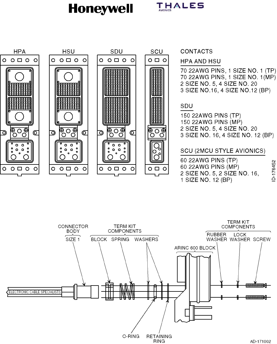
E. ARINC 600 Connectors
(1) ECS supplies ARINC 600 connectors for ARINC 741 style avionic electrical
interfaces. The SATCOM rack-side connectors (Figure A--1) are described in this
paragraph. Connector part numbers are:
(2) ECS supplies ARINC 600 Size 1 coaxial connectors with the requisite termination kit
and assembly instructions (Figure A--2).
SYSTEM DESCRIPTION, INSTALLATION, AND MAINTENANCE MANUAL
MCS--4200/7200 Multi--Channel SATCOM System
23--20--35 15 Jul 2006
Honeywell International Inc. Do not copy without express permission of Honeywell.
Page A--3
Figure A--1. ARINC Connectors
Figure A--2. ARINC Assembly

SYSTEM DESCRIPTION, INSTALLATION, AND MAINTENANCE MANUAL
MCS--4200/7200 Multi--Channel SATCOM System
23--20--35 15 Jul 2006
Honeywell International Inc. Do not copy without express permission of Honeywell.
Page A--4
F. SATCOM Avionics Unit Mounting Hardware
(1) SATCOM avionics mounting hardware is made up of the HPA, SDU, and SCU and
will be mounted in ARINC 600 style tray assemblies. The HPA and SDU each require
forced air cooling during normal operation, whereas the SCU can function properly
with convection cooling alone. Refer to MECHANICAL INSTALLATION, for LRU
cooling requirements.
G. SATCOM Hardware Component Kits
(1) This paragraph contains information on how to select SATCOM hardware component
kits offered by ECS for the Honeywell MCS--4200/7200 avionic units in Table A--3
thru Table A--8. ECS supplies several options for each kit to accommodate the variety
of mounting requirements specific to each aircraft installation. ECS tray assemblies
come with and without independent cooling systems to ensure installation flexibility.
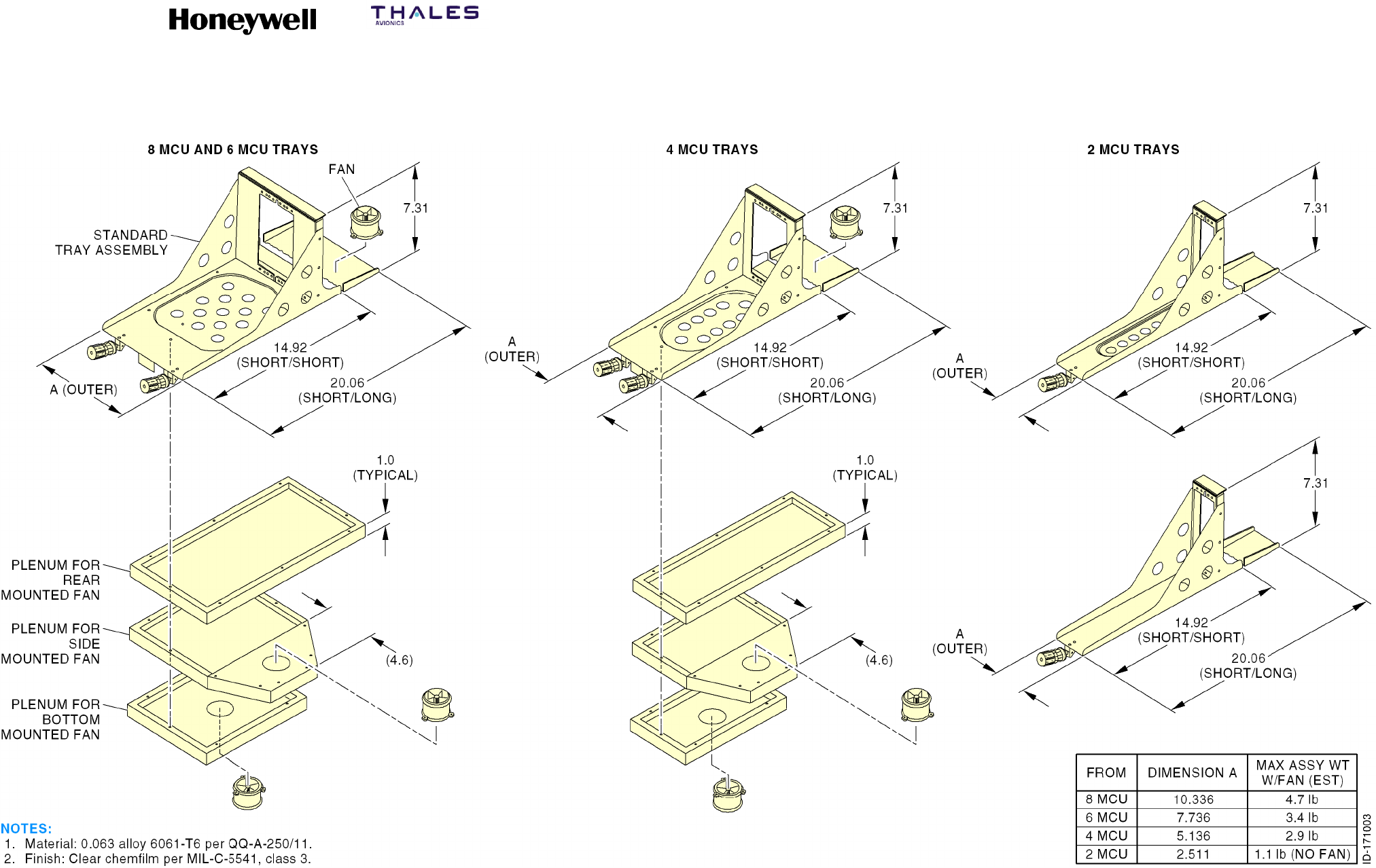
(2) The tray assemblies have been specially designed to meet Honeywell and ARINC
600 LRU cooling requirements. Tray assemblies are supplied with insertion/extraction
front hold-downs as standard, but are available with other front hold-down options.
For tray assembly dimensions refer to Figure A--3.
(3) The hardware component kits for the HPA, HSU, and SDU are listed in Table A--3
thru Table A--8, respectively.
SYSTEM DESCRIPTION, INSTALLATION, AND MAINTENANCE MANUAL
MCS--4200/7200 Multi--Channel SATCOM System
23--20--35 15 Jul 2006
Honeywell International Inc. Do not copy without express permission of Honeywell.
Page A--5/A--6
Figure A--3. Dimensions for ECS Tray Assemblies
SYSTEM DESCRIPTION, INSTALLATION, AND MAINTENANCE MANUAL
MCS--4200/7200 Multi--Channel SATCOM System
23--20--35 15 Jul 2006
Honeywell International Inc. Do not copy without express permission of Honeywell.
Page A--7/A--8
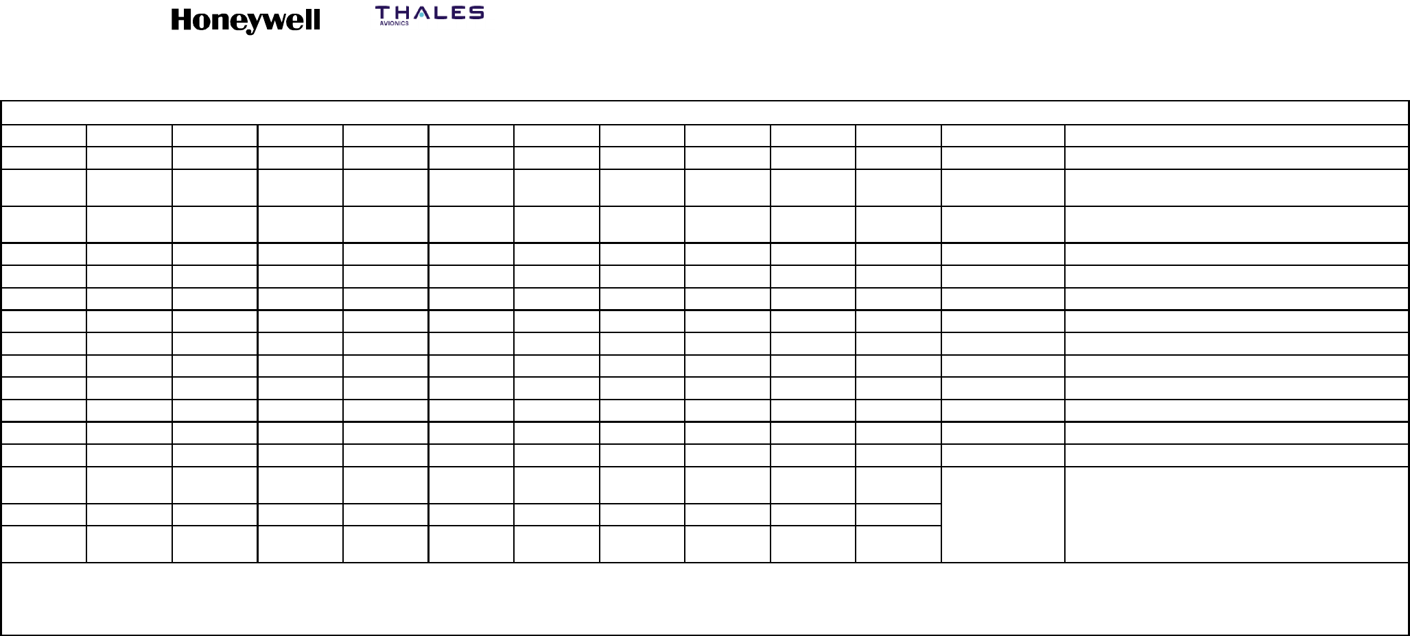
Table A--3. SD--720 (120--10141--1XX) Pressurized Hardware Kit
4 4 4 4 4 4 4 4 4 4 4 MS51957--29 6--32 X 7/16 IN. PAN HEAD
4 4 4 4 4 4 4 4 4 4 4 NAS1149DN616J WASHER, FLAT
1 1 1 1 1 1 1 1 1 1 1 NSXN2P201S01 SD--720 ARINC CONNECTOR W/PINS AND
SOCKETS (NOTE 1 AND 2)
1-- -- -- -- -- -- -- -- -- -- 6028--101 6 MCU TRAY SHORT, RIGHT SIDE DC FAN
-- 1-- -- -- -- -- -- -- -- -- 6068--101 6 MCU TRAY, SHORT, LEFT SIDE DC FAN
-- -- 1-- -- -- -- -- -- -- -- 6413--101 6 MCU TRAY, LONG, REAR DC FAN
-- -- -- 1-- -- -- -- -- -- -- 6013--102 6 MCU TRAY, SHORT, BOTTOM DC FAN
-- -- -- -- 1-- -- -- -- -- -- 6218--101 6 MCU TRAY, LONG, RIGHT REAR AC FAN
-- -- -- -- -- 1-- -- -- -- -- 6217--101 6 MCU TRAY, LONG, LEFT REAR AC FAN
-- -- -- -- -- -- 1-- -- -- -- 6080--101 6 MCU TRAY, LONG, NO FAN
-- -- -- -- -- -- -- 1-- -- -- 6110--101 6 MCU TRAY, SHORT, RIGHT SIDE AC FAN
-- -- -- -- -- -- -- -- 1-- -- 6216--101 6 MCU TRAY, SHORT, LEFT SIDE AC FAN
-- -- -- -- -- -- -- -- -- 16013--106 6 MCU TRAY, SHORT, BOTTOM AC FAN
-- -- -- -- -- -- -- -- -- -- 16035--101 6MCUTRAY,SHORT,NOFAN
QTY
REQ’D
QTY
REQ’D
QTY
REQ’D
QTY
REQ’D
QTY
REQ’D
QTY
REQ’D
QTY
REQ’D
QTY
REQ’D
QTY
REQ’D
QTY
REQ’D
QTY
REQ’D COMPONENTS
P
A
R
T
N
O
N
O
M
E
N
C
L
A
T
U
R
E
-- 111 -- 11 0 --109 --108 --107 --106 --105 --104 --103 --102 --101 PART NO.
O
R
N
O
M
E
N
C
L
A
T
U
R
E
OR
D
E
S
C
R
I
P
T
I
O
N
ASSEMBLY
P/N
ASSEMBLY
P/N
ASSEMBLY
P/N
ASSEMBLY
P/N
ASSEMBLY
P/N
ASSEMBLY
P/N
ASSEMBLY
P/N
ASSEMBLY
P/N
ASSEMBLY
P/N
ASSEMBLY
P/N
ASSEMBLY
P/N
O
R
IDENTIFYING NO. DESCRIPTION
NOTES:
1. ALTERNATE P/N: AD2--313--3AA00, NIC66H21A00AA0.
2. CONTACTS ARE: 22 AWG PINS, QTY OF 300; 20 AWG SOCKETS, QTY OF 4; 16 AWG SOCKETS. QTY OF 3; 12 AWG SOCKETS, QTY OF 4.
SYSTEM DESCRIPTION, INSTALLATION, AND MAINTENANCE MANUAL
MCS--4200/7200 Multi--Channel SATCOM System
23--20--35 15 Jul 2006
Honeywell International Inc. Do not copy without express permission of Honeywell.
Page A--9/A--10
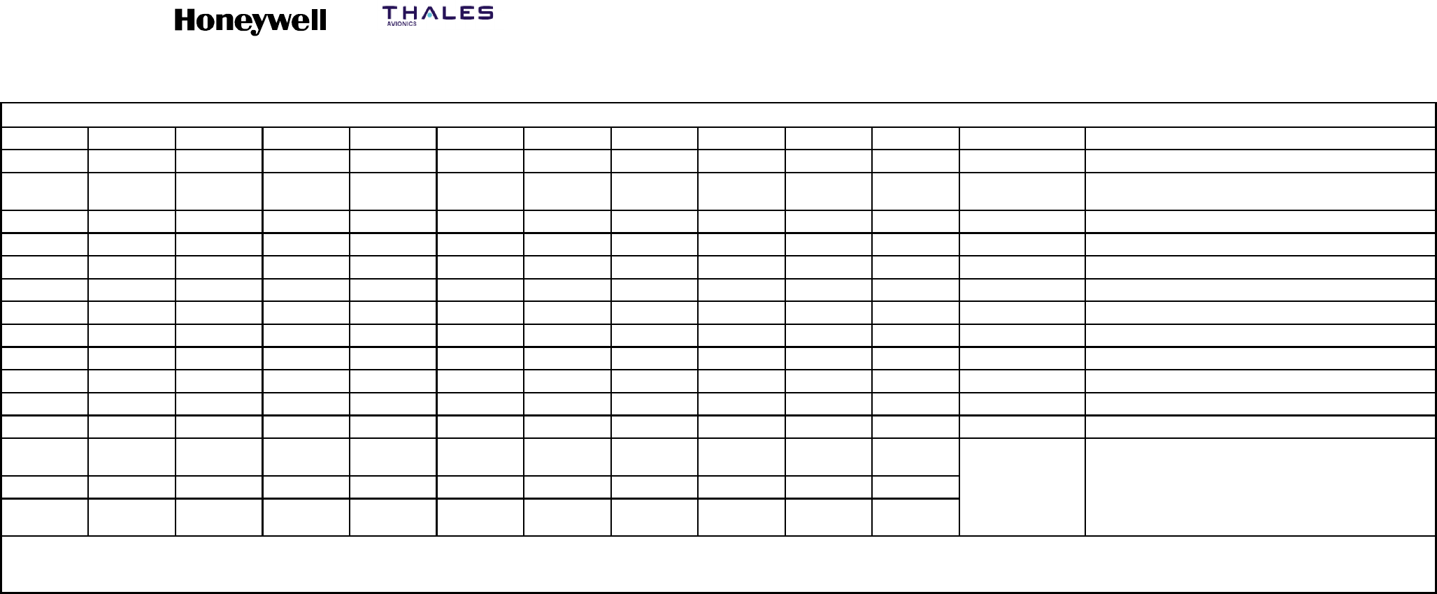
Table A--4. SD--720 (120--10142--1XX) Unpressurized Hardware Kit
4 4 4 4 4 4 4 4 4 4 4 MS51957--29 6--32 X 7/16 IN. PAN HEAD
4 4 4 4 4 4 4 4 4 4 4 NAS1149DN616J WASHER, FLAT
1 1 1 1 1 1 1 1 1 1 1 NSXN2P201S01 SD--720 ARINC CONNECTOR W/PINS
AND SOCKETS (NOTE 1 AND 2)
1-- -- -- -- -- -- -- -- -- -- 200--10276--101 6 MCU TRAY SHORT, RIGHT SIDE DC FAN
(NOTE 3)
-- 1-- -- -- -- -- -- -- -- -- 200--85743--101 6 MCU TRAY, SHORT, LEFT SIDE DC FAN
-- -- 1-- -- -- -- -- -- -- -- 200--93955--101 6 MCU TRAY, LONG, REAR DC FAN
-- -- -- 1-- -- -- -- -- -- -- 200--93112--101 6 MCU TRAY, SHORT, BOTTOM DC FAN
-- -- -- -- 1-- -- -- -- -- -- 6281--101 6 MCU TRAY, LONG, RIGHT REAR AC FAN
-- -- -- -- -- 1-- -- -- -- -- 6045--109 6 MCU TRAY, LONG, LEFT REAR AC FAN
-- -- -- -- -- -- 1-- -- -- -- 6080--101 6 MCU TRAY, LONG, NO FAN
-- -- -- -- -- -- -- 1-- -- -- 6282--101 6 MCU TRAY, SHORT, RIGHT SIDE AC FAN
-- -- -- -- -- -- -- -- 1-- -- 6232--101 6 MCU TRAY, SHORT, LEFT SIDE AC FAN
-- -- -- -- -- -- -- -- -- 1-- 6283--101 6 MCU TRAY, SHORT, BOTTOM AC FAN
-- -- -- -- -- -- -- -- -- -- 16035--101 6MCUTRAY,SHORT,NOFAN
QTY
REQ’D
QTY
REQ’D
QTY
REQ’D
QTY
REQ’D
QTY
REQ’D
QTY
REQ’D
QTY
REQ’D
QTY
REQ’D
QTY
REQ’D
QTY
REQ’D
QTY
REQ’D COMPONENTS
P
A
R
T
N
O
.
N
O
M
E
N
C
L
A
T
U
R
E
-- 111 -- 11 0 --109 --108 --107 --106 --105 --104 --103 --102 --101
P
A
R
T
N
O
.
OR
I
D
E
N
T
I
F
Y
I
N
G
N
O
M
E
N
C
L
A
T
U
R
E
OR
D
E
S
C
R
I
P
T
I
O
N
ASSEMBLY
P/N
ASSEMBLY
P/N
ASSEMBLY
P/N
ASSEMBLY
P/N
ASSEMBLY
P/N
ASSEMBLY
P/N
ASSEMBLY
P/N
ASSEMBLY
P/N
ASSEMBLY
P/N
ASSEMBLY
P/N
ASSEMBLY
P/N
IDENTIFYING
NO.
DESCRIPTION
NOTES:
1. ALTERNATE P/N: AD2--313--3AA00, NIC66H21A00AA0.
2. CONTACTS ARE: 22 AWG PINS, QTY OF 300; 20 AWG SOCKETS, QTY OF 4; 16 AWG SOCKETS, QTY OF 3; 12 AWG SOCKETS, QTY OF 4.
3. 200--10276--101 TRAY NOT CURRENTLY DESIGNED. APPROVED FAN ASSEMBLIES ARE: S0085--125, --134, --135, --138, AND --142.

SYSTEM DESCRIPTION, INSTALLATION, AND MAINTENANCE MANUAL
MCS--4200/7200 Multi--Channel SATCOM System
23--20--35 15 Jul 2006
Honeywell International Inc. Do not copy without express permission of Honeywell.
Page A--11/A--12
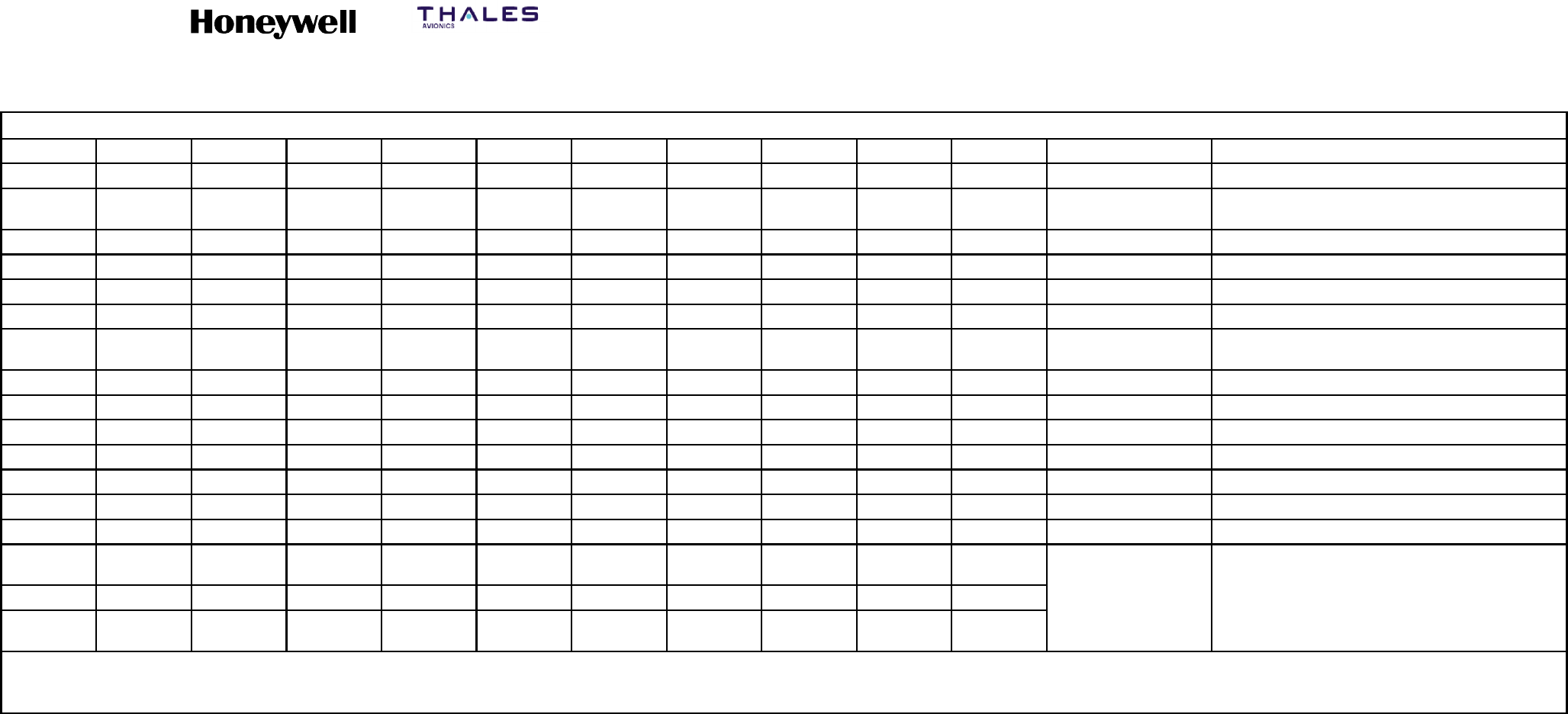
Table A--5. HS--720 (120--10267--1XX) Pressurized Hardware Kit
4 4 4 4 4 4 4 4 4 4 4 MS51957--29 6--32 X 7/16 IN. PAN HEAD
4 4 4 4 4 4 4 4 4 4 4 NAS1149DN616J WASHER, FLAT
1 1 1 1 1 1 1 1 1 1 1 NSXN2P221S01 HS--720 ARINC CONNECTOR W/PINS AND
SOCKETS (NOTE 1 AND 2)
1-- -- -- -- -- -- -- -- -- -- 200--10510--101 4 MCU TRAY SHORT, RIGHT SIDE DC FAN
-- 1-- -- -- -- -- -- -- -- -- 200--92609--101 4 MCU TRAY, SHORT, LEFT SIDE DC FAN
-- -- 1-- -- -- -- -- -- -- -- 200--92893--101 4 MCU TRAY, LONG, REAR DC FAN
-- -- -- 1-- -- -- -- -- -- -- 200--84977--101 4 MCU TRAY, SHORT, BOTTOM DC FAN
-- -- -- -- 11-- -- -- -- -- 6083--102 4 MCU TRAY, LONG, REAR AC FAN
-- -- -- -- -- -- 1-- -- -- -- 6026--101 4 MCU TRAY, LONG, NO FAN
-- -- -- -- -- -- -- 1-- -- -- 6049--102 4 MCU TRAY, SHORT, RIGHT SIDE AC FAN
-- -- -- -- -- -- -- -- 1-- -- 6049--101 4 MCU TRAY, SHORT, LEFT SIDE AC FAN
-- -- -- -- -- -- -- -- -- 1-- 6050--101 4 MCU TRAY, SHORT, BOTTOM AC FAN
-- -- -- -- -- -- -- -- -- -- 16034--101 4MCUTRAY,SHORT,NOFAN
QTY
REQ’D
QTY
REQ’D
QTY
REQ’D
QTY
REQ’D
QTY
REQ’D
QTY
REQ’D
QTY
REQ’D
QTY
REQ’D
QTY
REQ’D
QTY
REQ’D
QTY
REQ’D COMPONENTS
P
A
R
T
N
O
.
N
O
M
E
N
C
L
A
T
U
R
E
-- 111 -- 11 0 --109 --108 --107 --106 --105 --104 --103 --102 --101
P
A
R
T
N
O
.
OR
I
D
E
N
T
I
F
Y
I
N
G
N
O
M
E
N
C
L
A
T
U
R
E
OR
D
E
S
C
R
I
P
T
I
O
N
ASSEMBLY
P/N
ASSEMBLY
P/N
ASSEMBLY
P/N
ASSEMBLY
P/N
ASSEMBLY
P/N
ASSEMBLY
P/N
ASSEMBLY
P/N
ASSEMBLY
P/N
ASSEMBLY
P/N
ASSEMBLY
P/N
ASSEMBLY
P/N
IDENTIFYING
NO.
DESCRIPTION
NOTES:
1. ALTERNATE P/N: AD2--155C--3AA00, AD2--155C--30000, NIC66H20A00A00.
2. CONTACTS ARE: 22 AWG PINS, QTY OF 140; 20 AWG SOCKETS, QTY OF 4; 16 AWG SOCKETS, QTY OF 3; 12 AWG SOCKETS, QTY OF 4.
SYSTEM DESCRIPTION, INSTALLATION, AND MAINTENANCE MANUAL
MCS--4200/7200 Multi--Channel SATCOM System
23--20--35 15 Jul 2006
Honeywell International Inc. Do not copy without express permission of Honeywell.
Page A--13/A--14
Table A--6. HS--720 (120--10268--1XX) Unpressurized Hardware Kit
4 4 4 4 4 4 4 4 4 4 4 MS51957--29 6--32 X 7/16 IN. PAN HEAD
4 4 4 4 4 4 4 4 4 4 4 NAS1149DN616J WASHER, FLAT
1 1 1 1 1 1 1 1 1 1 1 NSXN2P221S01 HS--720 ARINC CONNECTOR W/PINS AND
SOCKETS (NOTE 1 AND 2)
1-- -- -- -- -- -- -- -- -- -- 200--10684--101 4 MCU TRAY SHORT, RIGHT SIDE DC FAN
-- 1-- -- -- -- -- -- -- -- -- 200--10683--101 4 MCU TRAY, SHORT, LEFT SIDE DC FAN
-- -- 1-- -- -- -- -- -- -- -- 200--85588--101 4 MCU TRAY, LONG, REAR DC FAN
-- -- -- 1-- -- -- -- -- -- -- 200--10682--101 4 MCU TRAY, SHORT, BOTTOM DC FAN
-- -- -- -- 11-- -- -- -- -- 6137--101 4 MCU TRAY, LONG, REAR AC FAN
-- -- -- -- -- -- 1-- -- -- -- 6026--101 4 MCU TRAY, LONG, NO FAN
-- -- -- -- -- -- -- 1-- -- -- 200--87190--101 4 MCU TRAY, SHORT, RIGHT SIDE AC FAN
-- -- -- -- -- -- -- -- 1-- -- 200--84496--101 4 MCU TRAY, SHORT, LEFT SIDE AC FAN
-- -- -- -- -- -- -- -- -- 1-- 6376--101 4 MCU TRAY, SHORT, BOTTOM AC FAN
-- -- -- -- -- -- -- -- -- -- 16034--101 4MCUTRAY,SHORT,NOFAN
QTY
REQ’D
QTY
REQ’D
QTY
REQ’D
QTY
REQ’D
QTY
REQ’D
QTY
REQ’D
QTY
REQ’D
QTY
REQ’D
QTY
REQ’D
QTY
REQ’D
QTY
REQ’D COMPONENTS
P
A
R
T
N
O
.
N
O
M
E
N
C
L
A
T
U
R
E
-- 111 -- 11 0 --109 --108 --107 --106 --105 --104 --103 --102 --101
P
A
R
T
N
O
.
OR
I
D
E
N
T
I
F
Y
I
N
G
N
O
M
E
N
C
L
A
T
U
R
E
OR
D
E
S
C
R
I
P
T
I
O
N
ASSEMBLY
P/N
ASSEMBLY
P/N
ASSEMBLY
P/N
ASSEMBLY
P/N
ASSEMBLY
P/N
ASSEMBLY
P/N
ASSEMBLY
P/N
ASSEMBLY
P/N
ASSEMBLY
P/N
ASSEMBLY
P/N
ASSEMBLY
P/N
IDENTIFYING
NO.
DESCRIPTION
NOTES:
1. ALTERNATE P/N: AD2--155C--3AA00, AD2--155C--30000, NIC66H20A00A00.
2. CONTACTS ARE: 22 AWG PINS, QTY OF 140; 20 AWG SOCKETS, QTY OF 4; 16 AWG SOCKETS, QTY OF 3; 12 AWG SOCKETS, QTY OF 4.
SYSTEM DESCRIPTION, INSTALLATION, AND MAINTENANCE MANUAL
MCS--4200/7200 Multi--Channel SATCOM System
23--20--35 15 Jul 2006
Honeywell International Inc. Do not copy without express permission of Honeywell.
Page A--15/A--16
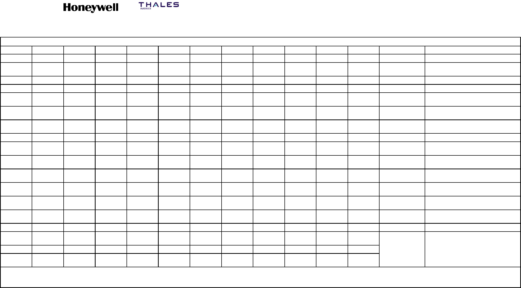
Table A--7. HP--720 (120--99510--1XX) Pressurized Hardware Kit
4 4 4 4 4 4 4 4 4 4 4 MS51957--29 6--32 X 7/16 IN. PAN HEAD
4 4 4 4 4 4 4 4 4 4 4 NAS1149DN616J WASHER, FLAT
1 1 1 1 1 1 1 1 1 1 1 NSXN2P221S01 HSD--128 ARINC CONNECTOR W/CONTACTS
(NOTE 1 AND 2)
1 1 1 1 1 1 1 1 1 1 1 MS25083--2BB8 6 INCH GROUNDING STRAP
1-- -- -- -- -- -- -- -- -- -- 200--96981--101 8 MCU S/S W/RIGHT MOUNTED DC FAN
-- 1-- -- -- -- -- -- -- -- -- 200--91171--101 8 MCU S/S TRAY W/LEFT MOUNTED DC FAN
-- -- 1-- -- -- -- -- -- -- -- 200--90568--101 8 MCU S/L W/REAR MOUNTED DC FAN
-- -- -- 1-- -- -- -- -- -- -- 200--88654--101 8 MCU S/S TRAY W/BOTTOM MOUNTED DC
FAN
-- -- -- -- 1-- -- -- -- -- -- 6117--103 8 MCU S/L TRAY W/RIGHT REAR AC FAN
-- -- -- -- -- 1-- -- -- -- -- 6117--101 8 MCU S/L TRAY W/LEFT REAR AC FAN
-- -- -- -- -- -- 1-- -- -- -- 6096--101 8 MCU S/L STANDARD TRAY
-- -- -- -- -- -- -- 1-- -- -- 6101--101 8 MCU S/S TRAY W/RIGHT SIDE AC FAN
-- -- -- -- -- -- -- -- 1-- -- 6100--101 8MCUS/STRAYW/LEFTSIDEACFAN
-- -- -- -- -- -- -- -- -- 16093--103 8 MCU S/S TRAY W/BOTTOM AC FAN
-- -- -- -- -- -- -- -- -- -- 16072--102 8 MCU S/S STANDARD TRAY
QTY
REQ’D
QTY
REQ’D
QTY
REQ’D
QTY
REQ’D
QTY
REQ’D
QTY
REQ’D
QTY
REQ’D
QTY
REQ’D
QTY
REQ’D
QTY
REQ’D
QTY
REQ’D COMPONENTS
P
A
R
T
N
O
N
O
M
E
N
C
L
A
T
U
R
E
-- 111 -- 11 0 --109 --108 --107 --106 --105 --104 --103 --102 --101 PART NO.
O
R
N
O
M
E
N
C
L
A
T
U
R
E
OR
D
E
S
C
R
I
P
T
I
O
N
ASSEMBLY
P/N
ASSEMBLY
P/N
ASSEMBLY
P/N
ASSEMBLY
P/N
ASSEMBLY
P/N
ASSEMBLY
P/N
ASSEMBLY
P/N
ASSEMBLY
P/N
ASSEMBLY
P/N
ASSEMBLY
P/N
ASSEMBLY
P/N
O
R
IDENTIFYING NO. DESCRIPTION
NOTES:
1. ALTERNATE P/N: 4D2--155C--3AA00, AD2--155C--30000, 4D2--155C--38900, BKAD2--V155M--301, NIC66H20A00AA0.
2. CONTACTS ARE: 22 AWG PINS, QTY OF 140; 20 AWG SOCKETS, QTY OF 4; 16 AWG SOCKETS, QTY OF 3; 12 AWG SOCKETS, QTY OF 4.
SYSTEM DESCRIPTION, INSTALLATION, AND MAINTENANCE MANUAL
MCS--4200/7200 Multi--Channel SATCOM System
23--20--35 15 Jul 2006
Honeywell International Inc. Do not copy without express permission of Honeywell.
Page A--17/A--18
Table A--8. HP--720 (120--99509--1XX) Unpressurized Hardware Kit
4 4 4 4 4 4 4 4 4 4 4 4 MS51957--29 6--32 X 7/16 IN. PAN HEAD
4 4 4 4 4 4 4 4 4 4 4 4 NAS1149DN616J WASHER
1 1 1 1 1 1 1 1 1 1 1 1 NSXN2P221S01 HSD--128 ARINC CONNECTOR
W/CONTACTS (NOTE 1 AND 2)
1 1 1 1 1 1 1 1 1 1 1 1 MS25083--2BB8 6 INCH GROUNDING STRAP
1-- -- -- -- -- -- -- -- -- -- -- 200--90568--101 8 MCU S/L W REAR DC FAN
-- 1-- -- -- -- -- -- -- -- -- -- 200--91171--102 8 MCU S/S W LEFT DC FAN &
FINGER GUARD
-- -- 1-- -- -- -- -- -- -- -- -- 200--91171--101 8MCUS/STRAYW/LEFTSIDEDC
FAN
-- -- -- 1-- -- -- -- -- -- -- -- 6--08S1C1C0 8 MCU S/S TRAY W/O COOLING AND
#10 MOUNTING HOLES
-- -- -- -- 1-- -- -- -- -- -- -- 200--91165--101 8 MCU S/S TRAY W/BOTTOM DC FAN
-- -- -- -- -- 1-- -- -- -- -- -- 6288--101 8MCUS/STRAYW/LEFTSIDEAC
FAN
-- -- -- -- -- -- 1-- -- -- -- -- 6269--101 8 MCU S/S TRAY W/BOTTOM AC
MOUNTED
-- -- -- -- -- -- -- 1-- -- -- -- 6286--101 8 MCU S/L TRAY W/RIGHT AC REAR
FAN
-- -- -- -- -- -- -- -- 1-- -- -- 6284--101 8 MCU S/L TRAY W/LEFT AC REAR
FAN
-- -- -- -- -- -- -- -- -- 1-- -- 6290--101 8 MCU S/S TRAY W/RIGHT AC SIDE
FAN
-- -- -- -- -- -- -- -- -- -- 1200--90202--101 8MCUS/STRAYW/LEFTSIDEAC
FAN/FILTER
-- -- -- -- -- -- -- -- -- -- -- 16292--101 8 MCU S/S TRAY W/BOTTOM FAN
QTY
REQ’D
QTY
REQ’D
QTY
REQ’D
QTY
REQ’D
QTY
REQ’D
QTY
REQ’D
QTY
REQ’D
QTY
REQ’D
QTY
REQ’D
QTY
REQ’D
QTY
REQ’D
QTY
REQ’D COMPONENTS
P
A
R
T
N
O
.
N
O
M
E
N
C
L
A
T
U
R
E
-- 11 2 -- 111 -- 1 1 0 --109 --108 --107 --106 --105 --104 --103 --102 --101
P
A
R
T
N
O
.
OR
I
D
E
N
T
I
F
Y
I
N
G
N
O
M
E
N
C
L
A
T
U
R
E
OR
D
E
S
C
R
I
P
T
I
O
N
ASSEMBLY
P/N
ASSEMBLY
P/N
ASSEMBLY
P/N
ASSEMBLY
P/N
ASSEMBLY
P/N
ASSEMBLY
P/N
ASSEMBLY
P/N
ASSEMBLY
P/N
ASSEMBLY
P/N
ASSEMBLY
P/N
ASSEMBLY
P/N
ASSEMBLY
P/N
IDENTIFYING
NO.
DESCRIPTION
NOTES:
1. ALTERNATE P/N: 4D2--155C--3AA00, AD2--155C--30000, 4D2--155C--38900, BKAD2--V155M--301, NIC66H20A00AA0.
2. CONTACTS ARE: 22 AWG PINS, QTY OF 140; 20 AWG SOCKETS, QTY OF 4; 16 AWG SOCKETS, QTY OF 3; 12 AWG SOCKETS, QTY OF 4.

SYSTEM DESCRIPTION, INSTALLATION, AND MAINTENANCE MANUAL
MCS--4200/7200 Multi--Channel SATCOM System
23--20--35 15 Jul 2006
Honeywell International Inc. Do not copy without express permission of Honeywell.
Page A--19
H. Air Filtration Assemblies
(1) ECS can supply air filtration assemblies for the HPA, SDU, and BSU tray assemblies
described in Table A--9. These filter assemblies offer protection against airborne
contaminants, such as dust and cigarette smoke. System
mean--time--between--failures (MTBF) can be significantly increased. Appendix B
supplies installation procedures for air filtration hardware.
I. SATCOM Shelf Assemblies
(1) ECS supplies customized and standard turnkey plenum shelf assemblies to
accommodate either single or dual SATCOM installations. A shelf assembly can
incorporate equipment trays, racking, and additional support structures, such as
disconnect panels, cover plates, and mounting brackets. ECS can supply
components that are compatible with all types of air transport aircraft.
NOTE: Some SATCOM system installation locations render the aircraft cooling
system inadequate. ECS has designed a self-contained cooling system for
the SATCOM shelf assembly that can be used in this type of installation.
J. Additional Avionics Installation Components
(1) ECS supplies a variety of additional components to support a SATCOM installation.
These include RF splitters, combiners, high power relays, maintenance panels,
placards, circuit breakers, and control annunciator panels.
K. Antenna System Provisions
(1) SATCOM antenna systems are available in numerous configurations. ECS supplies
installation provisions for each of these configurations.
•Some high-gain top-mounted antenna systems require a 2-MCU tray assembly
and an ARINC 600 connector for the BSU. Others require mounting bracketry for
the BSU. ECS supplies both BSU 2-MCU tray assembly, and connector and
mounting bracketry as required.
•ECS supplies trays and ARINC connectors for various SCUs in the market place.
•ECS supplies other antenna mounting hardware, such as mounting brackets for
the diplexer/low noise amplifier (D/LNA) and high- and low-gain antenna doublers.
L. Cabin Communications System Provisions
(1) ECS supplies ARINC 746 compliant air-to-ground communication systems installation
provisions. These provisions include mounting hardware and connectors, shelves,
racks, brackets, placards, cover plates, RF cable, connectors, cable assemblies, and
wire harness assemblies.
M. Wire Harnesses
(1) ECS can supply wire harness provisions that interface the SATCOM avionics with the
cabin communication units, the cabin communications units with the cabin phones,
and both the SATCOM avionics and cabin communication units with other aircraft
systems.

SYSTEM DESCRIPTION, INSTALLATION, AND MAINTENANCE MANUAL
MCS--4200/7200 Multi--Channel SATCOM System
23--20--35 15 Jul 2006
Honeywell International Inc. Do not copy without express permission of Honeywell.
Page A--20
(2) ECS wire harness assemblies can be custom designed and fabricated to meet
system installation requirements.
N. Complete Integrated SATCOM Installation Kits
(1) Complete system integration packages are available for ECS for virtually any given
installation requirements. These integration packages can include any of the
installation provisions discussed in this section, along with other customer-specified
components. ECS can also support Honeywell’s customers with systems installation
design engineering and certification design data packaging.
3. Hollingsead International
A. General
(1) This information aids you in selecting the engineering services and installation
provisions offered by Hollingsead International for the various MCS systems.
Hollingsead International is rapidly transforming into a world-class avionics and
aircraft systems integration leader, providing the capability to perform any or all of the
following:
•Design and manufacturing of the structural mounting for the MCS and all
associated avionics.
•Design and manufacturing of all wire and cable harness assembly interface
connections between the MCS and all associated avionics.
•Development of all engineering design substantiation, documentation, and testing
in support of FAA approval.
•Complete on-site support of a full installation team for the entire MCS installation
kit.
(2) You can contact them at the following address regarding your specific MCS program
requirements:
Hollingsead International
13701 Excelsior Drive
Santa Fe Springs, CA 90670
U.S.A.
Telephone: (310) 921-3438
FAX: (310) 921-6313
Telex: 691-462
B. Engineering Services
(1) As addressed in the previous paragraph, Hollingsead International supplies any level
of engineering support from minimal consultation to full turn-key. Full turn-key support
is defined as Hollingsead International undertaking the entire systems integration
from initial design through procurement and manufacture of parts to final installation
and certification on behalf on the customer.

SYSTEM DESCRIPTION, INSTALLATION, AND MAINTENANCE MANUAL
MCS--4200/7200 Multi--Channel SATCOM System
23--20--35 15 Jul 2006
Honeywell International Inc. Do not copy without express permission of Honeywell.
Page A--21
C. LRU Mounting Requirements
(1) MCS avionics are made up of the HPA, SDU, and BSU, which are mounted in ARINC
600 style tray assemblies. The HPA and SDU each require forced air cooling during
normal operation. The BSU and CMU, which are mounted in an ARINC 404 tray,
function properly with convection cooling alone.
D. Installation Kit Components
(1) General
(a) Complete system installation kits are available from Hollingsead International for
virtually any given installation requirement. These installation kits can include any
of the installation provisions discussed herein along with other
customer-specified components.
(2) Coaxial Cables
(a) All coaxial cables, connectors, and attenuators have been designed to fulfill the
MCS system and the ARINC 741 usage and attenuation requirements.
Hollingsead International supplies immediate access to several types and
manufacturers of coaxial cable, appropriate N or TNC connectors, and
attenuators to make sure the specific attenuation profiles for each aircraft
installation is achieved. These cables range in nominal attenuation from 1.27 to
16.3 dB per 100 feet at 1.6 GHz. The cable outer diameter range is from 0.206
inch to 1.55 inches. Each cable assembly is fabricated with an individual part
number and, where necessary, is assigned a serial number, which is
permanently affixed to each end. Serialization insures traceability and
reproducibility.
(b) Testing of each cable assembly is performed to verify insertion loss and VSWR.
The results become part of a test database and are shipped with each cable
assembly. Each cable assembly is tested across the MCS system frequency
bandwidth. Transmit path cable assemblies are test swept from 1626.5 MHz to
1660.5 MHz and receive path cable assemblies are test swept from 1530 MHz to
1559 MHz. Customers have the option of having cable assemblies tested with or
without attenuators.
(3) Connectors
(a) Hollingsead International supplies the appropriate ARINC connectors for ARINC
Characteristic 741 style avionics electrical interfaces. The SATCOM rack-side
connector blocks are appropriately mounted on each tray assembly. Hollingsead
International supplies ARINC 600 Size 1 coaxial connectors with the necessary
termination kit assembly instructions.
SYSTEM DESCRIPTION, INSTALLATION, AND MAINTENANCE MANUAL
MCS--4200/7200 Multi--Channel SATCOM System
23--20--35 15 Jul 2006
Honeywell International Inc. Do not copy without express permission of Honeywell.
Page A--22
(b) The connector part numbers are as follows:
•SDU -- C--06B3--0204--0100
•HPA -- C--06B3--0708--0100
•HSU -- C--06B3--0708--0100
•BSU -- C--06B1--0101--0100
•CMU -- DPX2MA--A106PA106P--33B--0001.
(4) Tray Assemblies
(a) Hollingsead International manufactures several tray assemblies for the MCS
avionics. These tray assemblies come with or without independent cooling
systems to ensure installation flexibility. Where forced air cooling is required,
these tray assemblies have been specially designed to meet the cooling
requirements of each LRU using a single fan. Tray assemblies are supplied with
insertion/extraction front hold-downs as standard, but are available with other
front hold-down options. Table A--9 identifies the various tray options and
Figure A--3 identifies the dimensions for each tray assembly.
Table A -- 9. Tray Assembly Part Numbers
Standard
T
a
Assembly Fan Location
Type
Tray
Assembly Bottom Left Side Right Side Left Rear Right Rear
8MCUS/S 1708006--101 1708007--101 1708008--101 1708008--102 N/A N/A
8MCUS/L 1708006--201 1708007--201 1708008--201 1708008--202 1708009--101 1708009--102
6MCUS/S 1706007--101 1706008--101 1706009--101 1706009--102 N/A N/A
6MCUS/L 1706007--201 1706008--201 1706009--201 1706009--202 1706010--101 1706010--102
4MCUS/S 1704008--101 1704009--101 1704010--101 1704010--102 N/A N/A
4MCUS/L 1704008--201 1704009--201 1704010--201 1704010--202 1704011--101 1704011--102
2MCUS/S 1702002--101 1702003--101
2MCUS/L 1702002--201 1702003--201
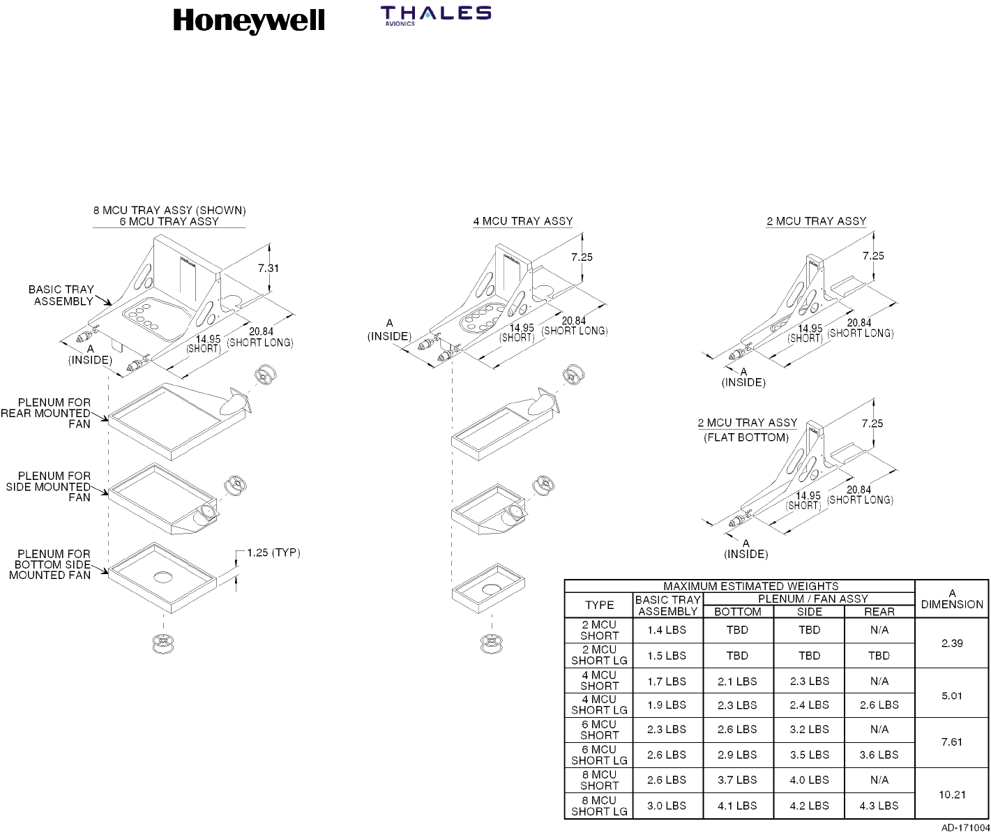
SYSTEM DESCRIPTION, INSTALLATION, AND MAINTENANCE MANUAL
MCS--4200/7200 Multi--Channel SATCOM System
23--20--35 15 Jul 2006
Honeywell International Inc. Do not copy without express permission of Honeywell.
Page A--23/A--24
Figure A--4. Dimensions for Hollingsead Tray Assemblies

SYSTEM DESCRIPTION, INSTALLATION, AND MAINTENANCE MANUAL
MCS--4200/7200 Multi--Channel SATCOM System
23--20--35 15 Jul 2006
Honeywell International Inc. Do not copy without express permission of Honeywell.
Page A--25
(5) Plenum Shelf Assemblies
(a) Hollingsead International supplies customized and standard turnkey plenum
shelf assemblies to accommodate either single or dual MCS system installations.
A shelf assembly can incorporate equipment trays, racking, and additional
support structures such as disconnect panels, cover plates, and mounting
brackets. Hollingsead International can supply components that are compatible
with all types of air transport aircraft.
(6) Additional Components
(a) Hollingsead International supplies a variety of additional components to support
an MCS installation, including RF splitters, combiners, high power relays,
maintenance panels, placards, circuit breakers, and control enunciator panels.
(7) Antenna System Provisions
(a) The antenna subsystems for the MCS system are available in numerous
configurations. Hollingsead International supplies installation provisions for each
of these configurations. Some high-gain, top-mounted antenna systems use a
2-MCU tray assembly and ARINC 600 connector for the BSU. Others use
mounting bracket hardware for the BSU. Hollingsead International supplies both
BSU 2-MCU tray assemblies and mounting bracket hardware as necessary.
Hollingsead International supplies other antenna mounting hardware such as
mounting brackets for the diplexer/LNA and high-gain and low-gain antenna
doublers.
(8) Cabin Communications System Provisions
(a) Hollingsead International supplies ARINC 746 compliant air-to-ground
communications system installation provisions. These provisions include
mounting hardware and connectors, shelves, racks, brackets, placards, cover
plates, RF cable, connectors, cable assemblies, and wire harness assemblies.
(9) Wire Harness Assemblies
(a) Hollingsead International wire harness assemblies are custom designed and
fabricated to meet each customer’s specific system installation requirements.
Hollingsead International supplies wire harness assemblies for the following
interfaces:
•MCS avionics and cabin communication units
•MCS avionics and flight deck data and voice communication sources
•Cabin communications units and cabin telephones
•Both the SATCOM avionics and cabin communication units with other aircraft
systems.

SYSTEM DESCRIPTION, INSTALLATION, AND MAINTENANCE MANUAL
MCS--4200/7200 Multi--Channel SATCOM System
23--20--35 15 Jul 2006
Honeywell International Inc. Do not copy without express permission of Honeywell.
Page A--26
4. Signal Conditioning Unit
A. General
(1) The SCU (Part No. 56047--010XX) is manufactured by ATS USA Inc. in the U.S.A.
Contact the project manager at the following address for additional information not
supplied in this section:
ATS USA Inc.
11410 Isaac Newton Square
Suite 210
Reston, VA 20190
U.S.A.
Telephone: (800) 709--0172
FAX: (888) 325--5808
(2) The MCS system requires ARINC 429 data for antenna pointing, antenna
stabilization, and Doppler frequency correction. These requirements are defined in
Table A--10. If the aircraft does not have an IRS that supplies this ARINC data, the
SCU can be used to supply the data.
(3) The SCU is packaged as an ARINC 600 2 MCU and weighs a maximum of 5.95
pounds (2.70 kilograms). The outer case of the SCU is constructed from two
half-shells identical in dimensions, which are made of an aluminum alloy 1.6
millimeters thick. The front and rear panels are made of the same alloy 3.3
millimeters thick. Both panels attach to the outer half-shells with corner brackets. Two
divider plates mount between the half-shells of the outer case to supply additional
rigidity and electrical shielding.
(4) The SCU translates and consolidates various input data formats into a two-wire
differential ARINC 429 high speed output for latitude and longitude position, true
heading, track angle, ground speed, and pitch and roll attitude. Program pins define
the particular type of data being received. These pins are interrogated at power on by
the software to determine the required configuration.
(5) The SCU operates from a nominal 115 V ac, 400 Hz single phase supply and/or from
28 V dc primary power. Input pins are supplied for both power sources in the ARINC
600 connector, and both power inputs can be connected to the aircraft power.
Current consumption depends on the input voltage and temperature, but is typically
0.25 amperes at 115 V ac or 0.40 amperes at 28 V dc.
SYSTEM DESCRIPTION, INSTALLATION, AND MAINTENANCE MANUAL
MCS--4200/7200 Multi--Channel SATCOM System
23--20--35 15 Jul 2006
Honeywell International Inc. Do not copy without express permission of Honeywell.
Page A--27
Table A--10. ARINC 429 Data Requirements
Label Definition
Minimum
Rate (MS)
Maximum
Rate (ms)
310 Latitude of present position 334 67
311 Longitude of present position 334 67
312 Ground speed 125 22
313 Track angle 55 22
314 True heading 55 22
324 Pitch 40 8
325 Roll 40 8
B. Operator Functions
(1) The front panel contains six LED indicators to allow monitoring of the SCU status.
However, these indicators are intended for use during repair by maintenance
personnel rather than by the operator during normal flight operation. Discrete outputs
representing the state of each LED indicator are also supplied for remote monitoring.
The functions of these discretes are defined in Table A--11.
Table A--11. SCU Discrete Functions
Color Nomenclature Function
Green Power Indicates SCU is on and all voltages are correct when lit.
Green SCU Valid Indicates correct operation of the SCU logic and processing
circuits when lit.
Red BIT Fail •Indicates normal operation when off.
•Indicates BIT is running repetitively when flashing slowly.
Indicates the SCU has failed BIT when steadily lit.
•Indicates the SCU has failed BIT when steadily lit.
Amber Signal 1 Indicates selection of input channel 1 when lit.
Amber Signal 2 Indicates selection of input channel 2 when lit.
Amber Signal 3 Indicates selection of input channel 3 when lit.
(2) Three amber LED indicators supply an error code that is displayed when the SCU
fails in the BIT mode. The red indicator lights and a three-bit code is continuously
displayed on the amber LEDs as indicated in Table A--12. BIT is interruptive and all
normal operation ceases during the time when the SCU is in the BIT mode.

SYSTEM DESCRIPTION, INSTALLATION, AND MAINTENANCE MANUAL
MCS--4200/7200 Multi--Channel SATCOM System
23--20--35 15 Jul 2006
Honeywell International Inc. Do not copy without express permission of Honeywell.
Page A--28
Table A--12. SCU Error Code
Failure Code LED 1 LED 2 LED 3
ARINC 429 translator not programmed 1ON OFF OFF
RAM read/write failed 2OFF ON OFF
ARINC 561 translator failed 3ON ON OFF
PROM checksum failed 4OFF OFF ON
ARINC 561 translator not programmed 5ON OFF ON
Discrete input failed 6OFF ON ON
ARINC 429 translator failed 7ON ON ON
C. Control Functions
(1) Normal operation of the SCU is fully automatic and does not require operator
intervention. Some control functions are supplied through the main ARINC 600
connector. These functions include:
•Remote SCU on/off control
•BIT initiate control
•Signal select A
•Signal select B
•Program pin A
•Program pin B
•Program pin C.
(2) The remote SCU on/off control line enables the operation of the SCU power supply.
The control line is active low and must be connected to ground to enable operation of
the SCU. An open circuit or 28 V dc on this line shuts down operation of the SCU.
(3) The BIT initiate control line is an active low input used to enable BIT in the SCU. The
BIT mode is an optional function that supplies a pre/post-flight confidence check and
is intended for use by maintenance personnel as a diagnostic tool. The SCU remains
in the BIT mode as long as the BIT initiate control line is grounded. An open circuit or
28 V dc on this control causes the SCU to return to normal operation.
(4) Signal selection is normally an automatic function under control of the internal SCU
program and is based on the validity of the received data. The signal select control
lines supply an override of this automatic function to allow manual selection of one
input from three available sources. The signal select control lines are active low and
are internally pulled high. Manual selection is accomplished by applying a ground to
the control lines as given in Table A--13.
SYSTEM DESCRIPTION, INSTALLATION, AND MAINTENANCE MANUAL
MCS--4200/7200 Multi--Channel SATCOM System
23--20--35 15 Jul 2006
Honeywell International Inc. Do not copy without express permission of Honeywell.
Page A--29
Table A--13. SCU Manual Signal Selection
Signal Select Control Lines
Function A B
Automatic Selection High High
Select Input No. 1 Low High
Select Input No. 2 High Low
Select Input No. 3 Low Low
D. System Functions
(1) Initialization
(a) Operation begins with BIT when the SCU is activated by applying aircraft power
and grounding the on/off control line. Testing normally takes approximately 0.5
second and when BIT passes normal operation begins. If the SCU fails the initial
BIT check, the unit latches in the BIT mode and displays an error code with the
amber LED indicators.
(2) Automatic Input Selection Mode
(a) There are three available data input channels. Unless a channel is manually
selected, the input to be used by the SCU is selected automatically. After initially
selecting Channel 1, the SCU checks for the presence of the required valid
words in the input data stream and the status of the attitude warning discrete
from the selected synchro channel. If all validity conditions are met within 1.6
seconds from the initial channel selection, the SCU locks on to the current
channel and continues to operate from that data source. The appropriate amber
LED indicator lights to indicate the selected channel to operator. If any of the
required data is invalid, the SCU cycles to the next input channel until a channel
providing a complete frame of valid data is received.
(3) Valid Channel Condition
(a) Conditions that must exist to let the SCU accept the current input channel
include:
•At least one new data word for each of the required labels is received within
the specified time period.
•The sign/status matrix (SSM) of all words for all required labels must be valid.
•The primary attitude warning input discrete must be in a valid state to indicate
the synchro inputs for attitude are usable.
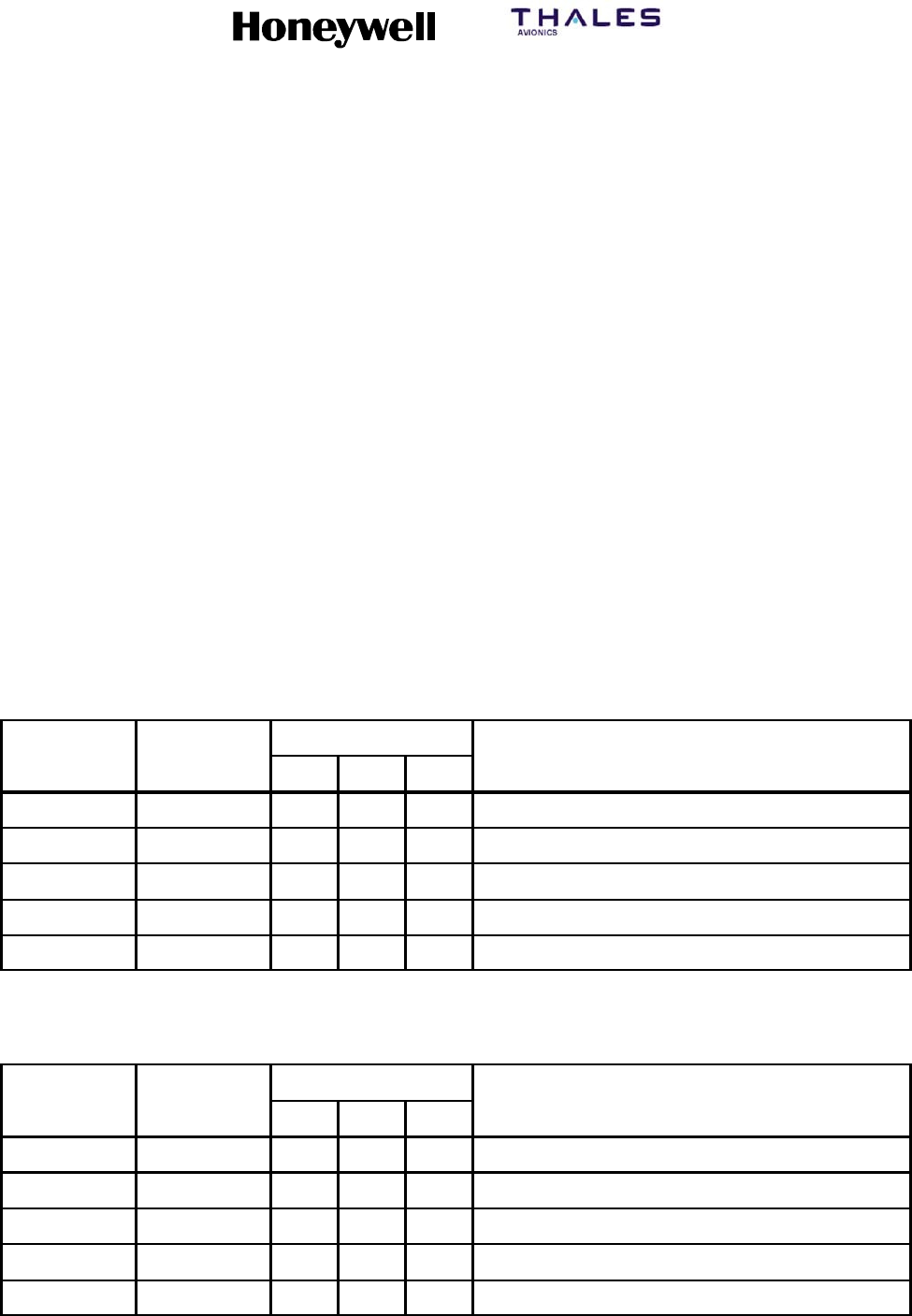
SYSTEM DESCRIPTION, INSTALLATION, AND MAINTENANCE MANUAL
MCS--4200/7200 Multi--Channel SATCOM System
23--20--35 15 Jul 2006
Honeywell International Inc. Do not copy without express permission of Honeywell.
Page A--30
(4) Channel Switching Timing
(a) The SCU allows 1.6 seconds for the selected input channel to receive a valid
data frame. However, if 1.6 seconds has passed and the valid channel
conditions have not been satisfied, the input channel cycles to the next
sequential channel. If all three input channels have been checked and none are
valid, the SCU prevents further cycling of the input channel selection for 1
minute. This prevents the SCU from continuously cycling when the inertial
navigation units or other sources of navigation data have not been initialized.
After the 1-minute delay, the SCU again initiates the checking cycle.
(5) Data Input
(a) A data subset made up of present latitude and longitude, true heading, track
angle, and ground speed is received through either the ARINC 561--6 wire inputs
or the ARINC 571--2 wire inputs as defined by the program pin selections. When
used as a selector of ARINC 404 data inputs, pitch and roll labels are also
included. The words are selected from the data stream by their octal labels while
other words are ignored. Program pin selections and associated data formats
and labels are defined in Table A--14 thru Table A--18.
Table A--14. ARINC 561 Binary Data
Program Pin
Octal Label Coded ABC Definition
310 Binary 000Latitude of present position
311 Binary 000Longitude of present position
212 Binary 000Ground speed
213 Binary 000Track angle
214 Binary 000True heading
Table A--15. ARINC 561 BCD Data
Program Pin
Octal Label Coded ABC Definition
010 BCD 100Latitude of present position
011 BCD 100Longitude of present position
012 BCD 100Ground speed
013 BCD 100Track angle
014 BCD 100True heading
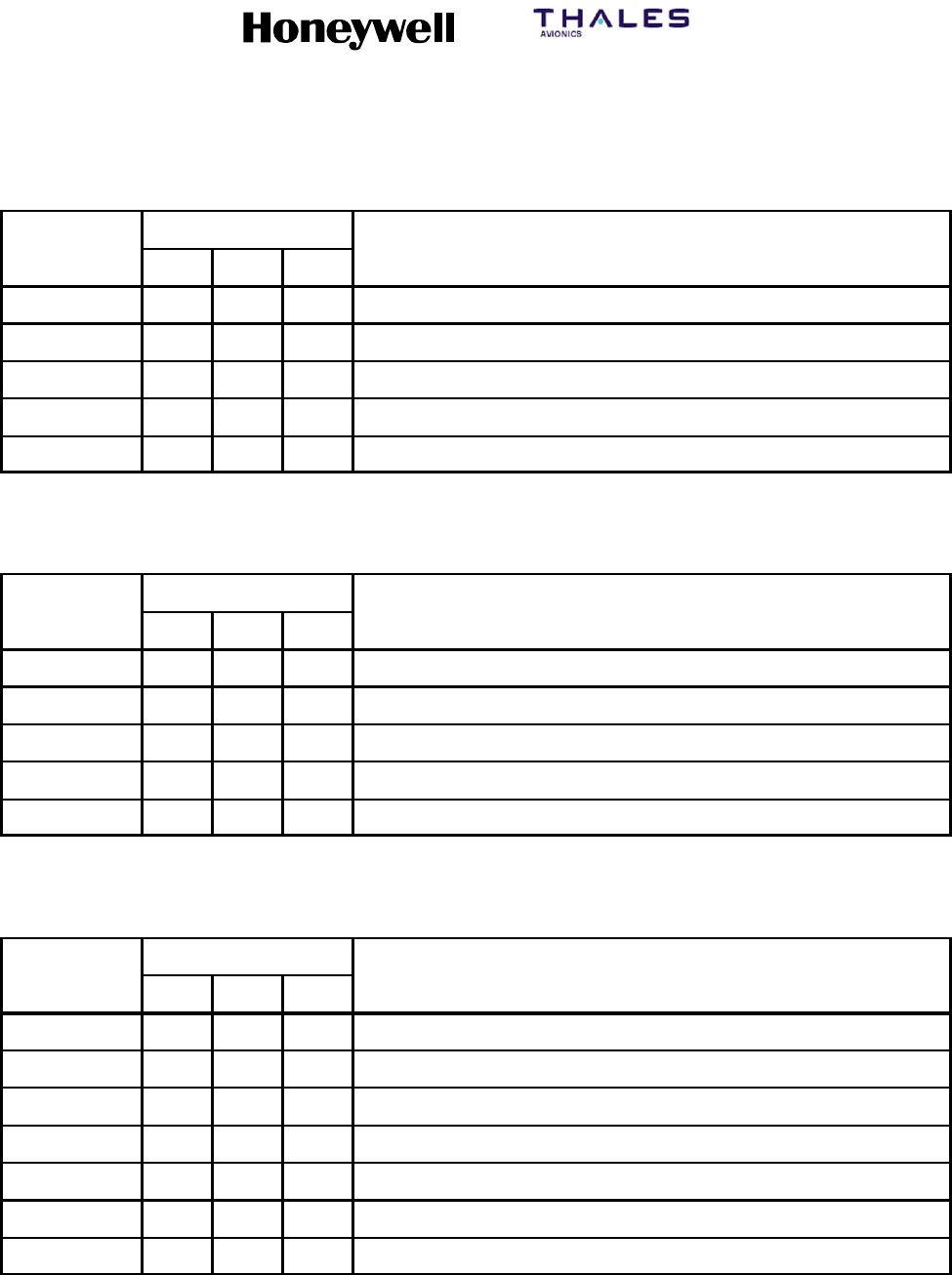
SYSTEM DESCRIPTION, INSTALLATION, AND MAINTENANCE MANUAL
MCS--4200/7200 Multi--Channel SATCOM System
23--20--35 15 Jul 2006
Honeywell International Inc. Do not copy without express permission of Honeywell.
Page A--31
Table A--16. ARINC 571 Data, ARINC 429 Format
Program Pin
Octal Label ABC Definition
310 010Latitude of present position
311 010Longitude of present position
212 010Ground speed
213 010Track angle
214 010True heading
Table A--17. ARINC 571 Data, ARINC 419 Format
Program Pin
Octal Label ABC Definition
210 110Latitude of present position
211 110Longitude of present position
212 110Ground speed
213 110Track angle
214 110True heading
Table A--18. ARINC 404 Data, ARINC 429 Format
Program Pin
Octal Label ABC Definition
310 001Latitude of present position
311 001Longitude of present position
312 001Ground speed
313 001Track angle
314 001True heading
324 001Pitch
325 001Roll
(b) The SSM of each received data word is checked. Valid words are converted to
ARINC 429 data. Invalid words are discarded.

SYSTEM DESCRIPTION, INSTALLATION, AND MAINTENANCE MANUAL
MCS--4200/7200 Multi--Channel SATCOM System
23--20--35 15 Jul 2006
Honeywell International Inc. Do not copy without express permission of Honeywell.
Page A--32
(c) With exception of the ARINC 404 input, the SCU also receives attitude data from
an associated attitude source. The attitude data is in the form of ARINC 407
pitch and roll synchro channels and an attitude warning flag. Attitude data is
selected from a source associated with the source selected for digital data. The
attitude inputs used are given in Table A--19.
Table A--19. SCU Attitude Data Inputs
Data Line Function
Roll Synchro X
Roll Synchro Y
Roll Synchro Z
Pitch Synchro X
Pitch Synchro Y
Pitch Synchro Z
Roll/Pitch Reference HI
Roll/Pitch Reference LO
Warning Flag HI Flag (HI = Good)
(d) The pitch and roll synchro inputs are read every 20 milliseconds. The attitude
warning flag is sampled before each computation to check the validity of the
input data before the data is accepted.
(6) Data Output
(a) The SCU transmits ARINC 429 serial words at a rate of one complete
seven-word message every 20 milliseconds. The SSMs in the navigation data
words are based on those supplied by the digital input words. The SSM data for
the attitude words is derived from computations and from the primary warning
flag.
(b) The data output is in accordance with ARINC 429 high speed data (100 kHz
clock speed). The SCU outputs ARINC 429 data on two separate ports operating
in parallel. Data from both ports is identical, but independent output buffers are
used to supply redundancy.
SYSTEM DESCRIPTION, INSTALLATION, AND MAINTENANCE MANUAL
MCS--4200/7200 Multi--Channel SATCOM System
23--20--35 15 Jul 2006
Honeywell International Inc. Do not copy without express permission of Honeywell.
Page A--33
E. ARINC 600 Connector Pin Assignments
(1) The rear connector (ARINC Part No. NIC66F11A00AA0) of the SCU complies with
ARINC Characteristic 600 as specified in the following:
•ARINC 600 -- Size MCU 2 no. 2 shell
•Type 0X top insert
•Type 0X middle insert
•Type 0X bottom insert
•Index pin code 0X.
(2) The contact arrangements for the connector are specified in Table A--20. An example
pin designation of BC12 for the table is given below.
Pin Designation Example: Pin BC12
Connector Cavity Identifier
Top C av ity = A
Middle Cavity = B
Bottom Cavity = C
Column Identifier
(A,B,C,orD)
Row Identifier
(1 thru 15)
B--C --12

SYSTEM DESCRIPTION, INSTALLATION, AND MAINTENANCE MANUAL
MCS--4200/7200 Multi--Channel SATCOM System
23--20--35 15 Jul 2006
Honeywell International Inc. Do not copy without express permission of Honeywell.
Page A--34
Table A--20. Contact Arrangements for SCU ARINC 600 Connector
Pin Function Remarks
AC1 ARINC 561 Data No. 1 (HI) Note 1.
AD1 ARINC 561 Data No. 1 (LO) Note 1.
AC2 ARINC 561 Clock No. 1 (HI) Note 1.
AD2 ARINC 561 Clock No. 1 (LO) Note 1.
AC3 ARINC 561 Strobe No. 1 (HI) or ARINC 429/419 Data No. 1 (HI) Note 1.
AD3 ARINC 561 Strobe No. 1 (LO) or ARINC 429/419 Data No. 1 (LO) Note 1.
AC4 Spare
AD4 Spare
AC5 Spare
AD5 Spare
AC6 Spare
AD6 Spare
AC7 Spare
AD7 Spare
AC8 Spare
AD8 Spare
AC9 ARINC 561 Data No. 3 (HI) Note 1.
AD9 ARINC 561 Data No. 3 (LO) Note 1.
AC10 ARINC 561 Clock No. 3 (HI) Note 1.
AD10 ARINC 561 Clock No. 3 (LO) Note 1.
AC11 ARINC 561 Strobe No. 3 (HI) or ARINC 429/419 Data No. 3 (HI) Note 1.
AD11 ARINC 561 Strobe No. 3 (LO) or ARINC 429/419 Data No. 3 (LO) Note 1.
AC12 Spare
AD12 Spare
AC13 ARINC 407 Pitch No. 1 X Note 2.
AD13 ARINC 407 Pitch No. 1 Y Note 2.
AC14 ARINC 407 Pitch No. 1 Z Note 2.
AD14 ARINC 407 Heading X Reserved
AC15 ARINC 407 Heading Y Reserved
AD15 ARINC 407 Heading Z Reserved

SYSTEM DESCRIPTION, INSTALLATION, AND MAINTENANCE MANUAL
MCS--4200/7200 Multi--Channel SATCOM System
23--20--35 15 Jul 2006
Honeywell International Inc. Do not copy without express permission of Honeywell.
Page A--35
Table A--20. Contact Arrangements for SCU ARINC 600 Connector (cont)
Pin RemarksFunction
AA1 ARINC 407 Pitch No. 3 X Note 2.
AB1 ARINC 407 Pitch No. 3 Y Note 2.
AA2 ARINC 407 Pitch No. 3 Z Note 2.
AB2 Attitude Warning No. 1 (From Attitude Source) Note 2.
AA3 ARINC 407 Reference No. 1 (HI)
AB3 ARINC 407 Reference No. 1 (LO)
AA4 ARINC 407 Heading Reference (HI) Reserved
AB4 ARINC 407 Heading Reference (LO) Reserved
AA5 ARINC 407 Reference No. 3 (HI)
AB5 ARINC 407 Reference No. 3 (LO)
AA6 Attitude Warning No. 3 (From Attitude Source) Note 2.
AB6 Spare
AA7 ARINC 407 Roll No. 1 X Note 2.
AB7 ARINC 407 Roll No. 1 Y Note 2.
AA8 ARINC 407 Roll No. 1 Z Note 2.
AB8 Spare
AA9 Spare
AB9 Spare
AA10 Spare
AB10 Spare
AA11 ARINC 407 Roll No. 3 X Note 2.
AB11 ARINC 407 Roll No. 3 Y Note 2.
AA12 ARINC 407 Roll No. 3 Z Note 2.
AB12 Spare
AA13 ARINC 404 Echo (HI) Note 3.
AB13 ARINC 404 Echo (LO) Note 3.
AA14 Spare
AB14 Spare
AA15 Spare
AB15 Spare

SYSTEM DESCRIPTION, INSTALLATION, AND MAINTENANCE MANUAL
MCS--4200/7200 Multi--Channel SATCOM System
23--20--35 15 Jul 2006
Honeywell International Inc. Do not copy without express permission of Honeywell.
Page A--36
Table A--20. Contact Arrangements for SCU ARINC 600 Connector (cont)
Pin RemarksFunction
BC1 ARINC 407 Pitch No. 2 X Note 2.
BD1 ARINC 407 Pitch No. 2 Y Note 2.
BC2 ARINC 407 Pitch No. 2 Z Note 2.
BD2 Spare
BC3 ARINC 407 Roll No. 2 X Note 2.
BD3 ARINC 407 Roll No. 2 Y Note 2.
BC4 Spare
BD4 ARINC 407 Roll No. 2 Z Note 2.
BC5 Spare
BD5 Attitude Warning No. 2 (From Attitude Source) Note 2.
BC6 ARINC 407 Reference No. 2 (HI)
BD6 ARINC 407 Reference No. 2 (LO)
BC7 Signal Source Select A (Input No. 1) Note 4.
BD7 Signal Source Select (Input No. 2) Note 4.
BC8 BIT initiate (Input No. 3) Note 5.
BD8 Spare
BC9 BIT Failed (Output No. 2) Reserved
BD9 SCU Valid Reserved
BC10 Superflag (+28 V dc = Output Valid) Note 6.
BD10 /Superflag (<1 V dc = Output Valid) Note 6.
BC11 Program Pin A (Input No. 5) Note 7.
BD11 Program Pin B (Input No. 6) Note 7.
BC12 Program Pin C (Input No. 7) Note 7.
BD12 Spare
BC13 Spare
BD13 Spare
BC14 Spare
BD14 Spare
BC15 ARINC 429 Out No. 1 (HI)
BD15 ARINC 429 Out No. 1 (LO)

SYSTEM DESCRIPTION, INSTALLATION, AND MAINTENANCE MANUAL
MCS--4200/7200 Multi--Channel SATCOM System
23--20--35 15 Jul 2006
Honeywell International Inc. Do not copy without express permission of Honeywell.
Page A--37
Table A--20. Contact Arrangements for SCU ARINC 600 Connector (cont)
Pin RemarksFunction
BA1 Spare
BB1 Spare
BA2 ARINC 429 Out No. 2 (HI)
BB2 ARINC 429 Out No. 2 (LO)
BA3 Spare
BB3 Spare
BA4 Discrete Out No. 3 (Select No. 2 LED) Reserved
BB4 Discrete Out No. 4 (Select No. 3 LED) Reserved
BA5 Discrete Out No. 5 (Select No. 1 LED) Reserved
BB5 Discrete Out No. 6 Reserved
BA6 Discrete Out No. 7 Reserved
BB6 Discrete Out No. 8 Reserved
BA7 ARINC 561 Data No. 2 (HI) Note 1.
BB7 ARINC 561 Data No. 2 (LO) Note 1.
BA8 ARINC 561 Clock No. 2 (HI) Note 1.
BB8 ARINC 561 Clock No. 2 (LO) Note 1.
BA9 ARINC 561 Strobe No. 2 (HI) or ARINC 429/419 Data No. 2 (HI) Note 1.
BB9 ARINC 561 Strobe No. 2 (LO) or ARINC 429/419 Data No. 2 (LO) Note 1.
BA10 +28 V dc Power Aircraft Power (Note 8.)
BB10 +28 V dc Power Aircraft Power (Note 8.)
BA11 0 V dc Power Return Aircraft Power (Note 8.)
BB11 0 V dc Power Return Aircraft Power (Note 8.)
BA12 Chassis Ground
BB12 Remote SCU On/Off Control Note 9.
BA13 Shield return Connected to Chassis
BB13 Shield Return Connected to Chassis
BA14 115 V ac Power 400 Hz (HI) Aircraft Power (Note 8.)
BB14 Chassis Ground
BA15 115 V ac Power 400 Hz (LO) Aircraft Power (Note 8.)
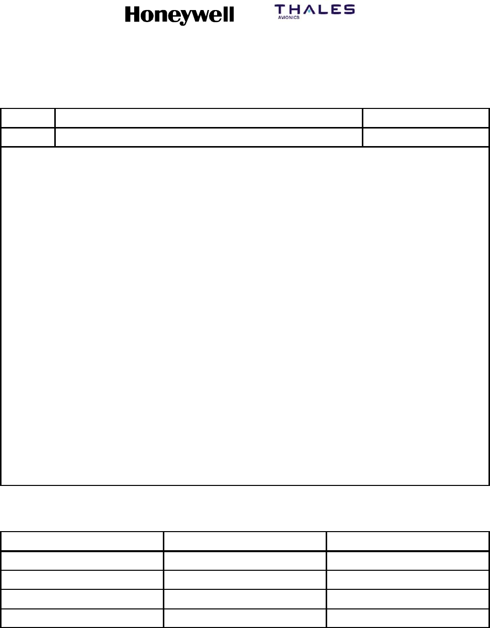
SYSTEM DESCRIPTION, INSTALLATION, AND MAINTENANCE MANUAL
MCS--4200/7200 Multi--Channel SATCOM System
23--20--35 15 Jul 2006
Honeywell International Inc. Do not copy without express permission of Honeywell.
Page A--38
Table A--20. Contact Arrangements for SCU ARINC 600 Connector (cont)
Pin RemarksFunction
BB15 Chassis Ground
NOTES:
1. The 6-wire ARINC 561 or 2-wire ARINC 429/419 (ARINC 571/404) data can be routed from up to three sources.
However, if a single input is supplied, it should be connected to the No. 1 inputs as indicated. Inputs No. 2 and 3
should be left open. The type of data being used, either ARINC 561 or ARINC 571/404, must be indicated by
selecting the proper program pins as specified in NOTE 7. Also, refer to NOTE 4. for more information on selecting
a specific input as the data source.
2. The synchro pitch and roll data can be routed from up to three sources. However, sources of attitude data must be
paired with sources of ARINC 561 or ARINC 571 data. Thus, if only one source of ARINC 561 or ARINC 571 data
is available, then only one source of attitude data can be used. An attitude warning flag for each source of attitude
that is active must be supplied. +28 V dc = valid. Ground or open = invalid.
3. When the SCU is used as a selector/controller of multiple ARINC 404 compatible data sources, the receiving
equipment should be connected to the ARINC 404 echo outputs. In this configuration, the input as valid by the
SCU is routed back out of the unit on these pins. Since attitude data is embedded in the ARINC 404 data stream,
no attitude inputs are used.
4. When multiple sources of data are available and routed to the SCU, it automatically searches for an input with valid
attitude data and ARINC 561/571 data. If only one source of ARINC 561/571 data and attitude data is available, the
SCU should be connected to only one input and the signal source select lines should be linked as applicable for
the selected input as given in Table A--21.
5. Grounding the BIT initiate input forces the SCU to enter the interruptive BIT mode and repetitively do its BIT
routines until ground is removed. BIT is automatically done at each power-up cycle. This input should be an open, if
not used.
6. The superflag output is +28 V dc whenever the SCU is operating normally and the output data is valid. If a portion
of the input data is invalid or the SCU detects an internal fault, then the superflag output is 0 V dc. The /superflag
output is the inverse of the superflag output.
7. The data format and characteristics accepted by the SCU are programmable through pins A, B, and C. The
combinations supported by the SCU are specified in Table A--22.
8. The SCU operates from either +28 V dc or 115 V ac, 400 Hz power. The power source not used should remain
unconnected.
9. The remote SCU on/off control can be used to power down the SCU from a remote location. A ground activates the
unit and an open switches the unit off. If remote control is not required, this pin should be permanently grounded at
the connector.
Table A--21. Signal Source Select Lines
Signal Source Select A B
Auto Open Open
Input No.1 Ground Open
Input No. 2 Open Ground
Input No. 3 Ground Ground
SYSTEM DESCRIPTION, INSTALLATION, AND MAINTENANCE MANUAL
MCS--4200/7200 Multi--Channel SATCOM System
23--20--35 15 Jul 2006
Honeywell International Inc. Do not copy without express permission of Honeywell.
Page A--39
Table A--22. SCU Program Pin Combinations
Program Pins
ABC Input Description
000ARINC 561 data, binary labels, synchro attitude
100ARINC 561 data, BCD labels, synchro attitude
010ARINC 571 data with ARINC 429 format, synchro attitude
110ARINC 571 data with ARINC 419 format, synchro attitude
NOTE: Ground = 1; open = 0.

SYSTEM DESCRIPTION, INSTALLATION, AND MAINTENANCE MANUAL
MCS--4200/7200 Multi--Channel SATCOM System
23--20--35 15 Jul 2006
Honeywell International Inc. Do not copy without express permission of Honeywell.
Page A--40
Blank Page

SYSTEM DESCRIPTION, INSTALLATION, AND MAINTENANCE MANUAL
MCS--4200/7200 Multi--Channel SATCOM System
23--20--35 15 Jul 2006
Honeywell International Inc. Do not copy without express permission of Honeywell.
Page B--1
APPENDIX B
INSTALLATION PROCEDURES FOR SATCOM AIR FILTRATION
SYSTEMS
1. Introduction
A. General
(1) Appendix B contains information on the different air filtration systems available for the
SATCOM installations. Procedures for installing these air filtration systems are also
supplied. After you have determined the proper air filtration system for your needs,
follow the appropriate procedures in paragraph 4.
(2) The SATCOM system (SDU and HPA) is designed to ARINC 600 standards including
ARINC 600 cooling requirements. ARINC 600 calls for the cooling air to contain no
contamination particles in excess of 400 microns. Several installation designs do not
supply cooling air in accordance with ARINC 600. The OEM installation design for the
B747, B767, and B777 supply unfiltered cooling air (cabin air) to the SATCOM LRUs.
As a result, contaminants in the air tend to accumulate on and inside the LRUs
sometimes blocking off the cooling air passages. This leads to units operating at a
higher temperature, which can result in decreasing the MTBF of the units.
(3) Filter assemblies have been designed that attach to the SATCOM LRUs or to the
LRU trays. These filter assemblies contain filter media that filter out contaminants
before entering the LRUs. This design is for installations where the cooling air is
drawn through the LRU top to bottom, and where there is at least 1 inch of clearance
above the LRUs to allow for the assembly itself. Thus, the air filtration units included
in this appendix are acceptable for installation on the B747 and B777 aircraft, but
because of clearance problems, are not acceptable for installation on the
OEM-provisioned B767 aircraft.
2. Continued Airworthiness
A. General
CAUTION: THE FILTER MEDIA MUST BE REPLACED (OR CLEANED) APPROXIMATELY
EVERY 4000 FLIGHT HOURS OR EVERY C CHECK, WHICHEVER COMES
FIRST, OR THE EFFECTIVENESS OF THE AIR FILTRATION ASSEMBLY CAN
BE DEGRADED.
(1) The selection of the type of filter media cartridge is based on the following:
•Effectiveness of the filter media in removing contaminants from the cooling air
before entering the SATCOM LRUs.
•Impact of the filter media on the cooling air mass flow rate through the units.
•Time between removals.
SYSTEM DESCRIPTION, INSTALLATION, AND MAINTENANCE MANUAL
MCS--4200/7200 Multi--Channel SATCOM System
23--20--35 15 Jul 2006
Honeywell International Inc. Do not copy without express permission of Honeywell.
Page B--2
3. Equipment and Materials
A. General
CAUTION: DO NOT USE MATERIALS THAT ARE NOT EQUIVALENT TO
MATERIALS SPECIFIED BY HONEYWELL. MATERIALS NOT
EQUIVALENT CAN CAUSE DAMAGE TO THE EQUIPMENT AND CAN
MAKE THE WARRANTY NOT APPLICABLE.
(1) Refer to Table B--1 for a list of materials.
Table B--1. Materials
Item Description Source
HMN 9730178 Retaining compound
(MIL--S--22473, grade A) — Grade
A
Loctite Corp, Rocky Hill, CT
(05972)
HMN 9731178 Primer for retaining compound,
ready--to--use, quick
(MIL--S--22473, grade T, form R)
— Locquic Grade T
NOTES: NOTES:
1. Equivalent alternatives are permitted for equipment and materials in this list.
2. The HMN codes in the list of materials identify the Honeywell Material Number (HMN) given to each material.
(2) The equipment listed in Table B--2, Table B--3, and Table B--4 supplies the necessary
hardware to install air filtration systems on the aircraft. Find the air filtration system
and filter that best fits your needs and contact the company that manufacturers that
particular equipment.
Table B--2. Air Filtration Systems from ECS for a Top Mount Assembly
Equipment Quantity LRU Part No. SATCOM System
SATCOM Filter Assembly 1SDU 10919--101 6--MCU assembly
SATCOM Filter Assembly 1HPA (20W) 10968--101 4--MCU assembly
SATCOM Filter Assembly 1HPA (40W) 10923--101 8--MCU assembly
Filter Cartridge Assembly 1SDU 10907--105 6--MCU assembly
Filter Cartridge Assembly 1HPA (20W) 10907--104 4--MCU assembly
Filter Cartridge Assembly 1HPA (40W) 10907--106 8--MCU assembly
SYSTEM DESCRIPTION, INSTALLATION, AND MAINTENANCE MANUAL
MCS--4200/7200 Multi--Channel SATCOM System
23--20--35 15 Jul 2006
Honeywell International Inc. Do not copy without express permission of Honeywell.
Page B--3
Table B--3. Air Filtration Systems from ECS for a Body--Mounted Design
Equipment Quantity LRU Part No. SATCOM System
SATCOM Filter Assembly 1SDU P0329--106 6--MCU assembly
SATCOM Filter Assembly 1HPA (20W) P0329--104 4--MCU assembly
SATCOM Filter Assembly 1HPA (40W) P0329--108 8--MCU assembly
Filter Cartridge Assembly 1SDU 20008--05 6--MCU assembly
Filter Cartridge Assembly 1HPA (20W) 20008--04 4--MCU assembly
Filter Cartridge Assembly 1HPA (40W) 20008--06 8--MCU assembly
Table B--4. Air Filtration Systems from ECS for a Tray--Mounted Design
Equipment Quantity LRU Part No. SATCOM System
SATCOM Filter Assembly 1SDU 20005--103 6--MCU assembly
SATCOM Filter Assembly 1HPA (20W) 20005--102 4--MCU assembly
SATCOM Filter Assembly 1HPA (40W) 20005--104 8--MCU assembly
Filter Cartridge Assembly 1SDU 20008--05 6--MCU assembly
Filter Cartridge Assembly 1HPA (20W) 20008--04 4--MCU assembly
Filter Cartridge Assembly 1HPA (40W) 20008--06 8--MCU assembly

SYSTEM DESCRIPTION, INSTALLATION, AND MAINTENANCE MANUAL
MCS--4200/7200 Multi--Channel SATCOM System
23--20--35 15 Jul 2006
Honeywell International Inc. Do not copy without express permission of Honeywell.
Page B--4
4. Installation Instructions
A. Top Mount Assembly
(1) The ECS top mount air filtration assembly is designed to clamp to the top of the
SATCOM LRUs so it does not come off the LRU. Once attached to the top of the
LRU, it forms a seal letting only filtered air enter the LRU. The assembly is held to the
top of the LRU by friction from the sides of the assembly and by the clamps that
supply friction to the front and rear panels of the unit. Figure B--1 shows the location
of the components for the following procedures.
(2) Install the filter assembly to an SDU or HPA using the following steps.
(a) Make sure the correct size assembly is selected for the given LRU (refer to
Table B--2).
(b) OPTIONAL — Remove the SATCOM LRU from its tray and set it on a secure
surface. (The assembly can be installed while the unit is in the rack.)
(c) Install the air filtration media inside the air filtration assembly in the rectangular
filter frame.
(d) Place the filter assembly over the top of the LRU with the clamps in the up
(thumb lever over the top of the filter assembly) position and pointing toward you.
(e) Push down on the air filtration unit until it fits over the top of the SATCOM LRU.
The sides of the air filtration assembly may need to be spread open slightly prior
to sliding over the sides of the LRU.
(f) Once the air filtration unit is firmly seated to the top of the LRU, clamp the
assembly to the unit by pushing down on the two thumb levers until they lock into
position. The thumb levers pass through approximately 180 degrees of rotation
for the clamping process.
(g) Make sure the air filtration assembly remains seated firmly against the top of the
LRU to maintain the air seal.
(h) Make sure the air filtration assembly is held tightly to the unit by gently lifting up
on the assembly; making sure the assembly does not pull off of the LRU.
(i) OPTIONAL -- Install the SATCOM LRU back into its tray if removed in step
4.A.(2)(b).
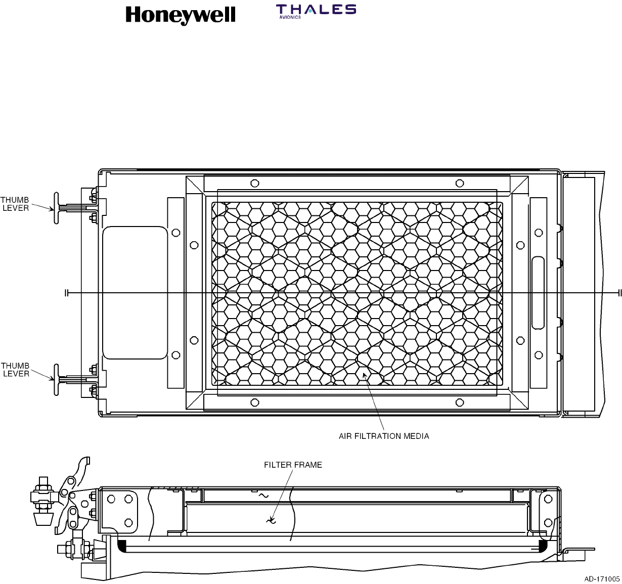
SYSTEM DESCRIPTION, INSTALLATION, AND MAINTENANCE MANUAL
MCS--4200/7200 Multi--Channel SATCOM System
23--20--35 15 Jul 2006
Honeywell International Inc. Do not copy without express permission of Honeywell.
Page B--5/B--6
Figure B--1. ECS Top Mount Air Filtration Assembly

SYSTEM DESCRIPTION, INSTALLATION, AND MAINTENANCE MANUAL
MCS--4200/7200 Multi--Channel SATCOM System
23--20--35 15 Jul 2006
Honeywell International Inc. Do not copy without express permission of Honeywell.
Page B--7
(3) Replace the filter media according to the following steps.
(a) Gain access to the SATCOM LRUs.
(b) Lift up on the two thumb levers (approximately 180 degrees).
(c) Pull up on the air filtration unit until it lifts off the top of the SATCOM LRU. The
sides of the air filtration assembly may need to be spread open slightly prior to
sliding up the sides of the LRU.
(d) Remove the air filtration media from the air filtration assembly in the rectangular
filter frame.
(e) Once the assembly is removed, pull the filter assembly out of its retaining fixture
and discard the filter appropriately.
(f) Obtain a new filter.
(g) Make sure the correct size filter assembly is selected for the given LRU (refer to
Table B--2).
(h) Install the new filter media into the filter assembly retaining fixture.
(i) OPTIONAL — Remove the SATCOM LRU from its tray and set on a secure
surface. (The assembly can be installed while the unit is in the rack.)
(j) Install the air filtration media inside the air filtration assembly in the rectangular
filter frame.
(k) Place the filter assembly over the top of the LRU with the clamps in the up
(thumb lever over the top of the filter assembly) position and pointing toward you.
(l) Push down on the air filtration unit until it fits over the top of the SATCOM LRU.
The sides of the air filtration assembly may need to be spread open slightly prior
to sliding over the sides of the LRU.
(m) Once the air filtration unit is firmly seated to the top of the LRU, clamp the
assembly to the unit by pushing down on the two thumb levers until they lock into
position. The thumb levers will pass through approximately 180 degrees of
rotation for the clamping process.
(n) Make sure the air filtration assembly remains seated firmly against the top of the
LRU to maintain the air seal.
(o) Make sure the air filtration assembly is held tightly to the unit by gently lifting up
on the assembly to verify the assembly does not pull off the LRU.
(p) OPTIONAL -- Install the SATCOM LRU back into its tray if removed in step
4.A.(3)(i).

SYSTEM DESCRIPTION, INSTALLATION, AND MAINTENANCE MANUAL
MCS--4200/7200 Multi--Channel SATCOM System
23--20--35 15 Jul 2006
Honeywell International Inc. Do not copy without express permission of Honeywell.
Page B--8
B. Body--Mounted Assembly
(1) The ECS body-mounted air filtration assembly is designed to strap around the body
of the SATCOM LRUs in a way that it will not come off the LRU. Once attached to the
LRU, it forms a seal allowing only filtered air to enter the LRU. The assembly is held
to the top of the LRU with a strap that fits securely around the body of the unit. The
filtration unit sits on top of the SATCOM LRU. The strap runs down the side,
underneath, and up the other side of the LRU. By way of a clamping system on top of
the LRU, the strap is pulled tight, which firmly secures the filter assembly to the top of
the unit.
(2) Install the filter assembly to an SDU or HPA according to the following steps.
(a) Make sure the correct size assembly is selected for the given LRU
(refer to Table B--3).
(b) Remove the SATCOM LRU from its tray and set it on a secure surface.
(c) Slide the filter strap around the front of the LRU so the strap is underneath and
coming up each side of the LRU.
(d) Place the filter assembly on top of the LRU so the back lip of the assembly unit
fits over the back of the LRU.
(e) Pull the strap around the top of the filter assembly unit so the two ends of the
strap overlap. The strap should come over the top of the filter assembly on the
front end of the assembly (dog-house end of the LRU). A channel is built into the
filter assembly for the strap.
(f) With the strap in place, latch the strap together by inserting the lips of the strap
ends together so they latch together. With the LRU facing you, the strap on the
left-hand side should latch over the top of the strap on the right-hand side.
(g) Once the strap is latched, make sure the lip on the rear of the filter assembly is
seated firmly just over the rear of the LRU.
(h) Make sure the filter retainer mechanism is latched closed.
(3) Replace the filter media according to the following steps. Figure B--2 shows the
location of the components used.
(a) Gain access to the SATCOM LRUs.
(b) Locate the filter retaining clips located on the forward end of the filter assembly
mechanism.
(c) Slide the retainer clips (one on the left and one on the right) out to disengage the
clips from the latching pins.
(d) Lift the filter retaining tray up, (hinged on the rear side) remove the filter media
cartridge and discard the filter appropriately.

SYSTEM DESCRIPTION, INSTALLATION, AND MAINTENANCE MANUAL
MCS--4200/7200 Multi--Channel SATCOM System
23--20--35 15 Jul 2006
Honeywell International Inc. Do not copy without express permission of Honeywell.
Page B--9
(e) Install the new filter media by placing a new filter media cartridge in the filter
retaining tray chamber.
(f) Lower the filter retaining tray down until the locating pins protrude through the
clearance holes on the filter retaining tray.
(g) Slide the retaining clips (left and right) in until they latch around the latching pins.
C. Tray--Mounted Assembly
(1) The ECS tray-mounted air filtration assembly is designed as an integral part of the
equipment tray and does not attach to the LRU itself. The SATCOM LRU slides into
the tray, sandwiched between the tray and plenum below, and the air filtration
assembly above. Since the air filtration assembly is an integral part of the equipment
tray, in order to install this type of assembly, a modified equipment tray must be
purchased for each LRU.
(2) Replace the filter media according to the following steps. Figure B--2 shows the
location of the components used.
(a) Gain access to the SATCOM LRUs.
(b) Locate the filter retaining clips located on the forward end of the filter assembly
mechanism.
(c) Slide the retainer clips (one on the left and one on the right) out to disengage the
clips from the latching pins.
(d) Lift the filter retaining tray up (hinged on the rear side) and remove the filter
media cartridge. Discard the filter media cartridge appropriately.
(e) Install the new filter media by placing a new filter media cartridge in the filter
retaining tray chamber.
(f) Make sure the filter cartridge is supported on the air plenum seals. The direction
of airflow through the filter is not important.
(g) Lower the filter retaining tray until the locating pins protrude through the
clearance holes on the filter retaining tray.
(h) Slide the retaining clips (left and right) in until they latch around the latching pins.
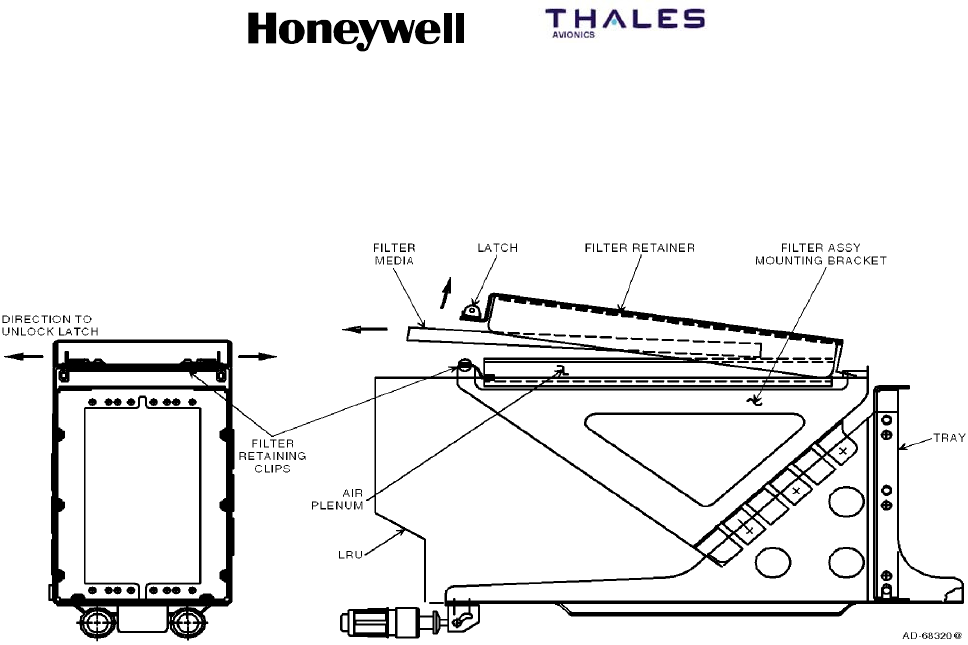
SYSTEM DESCRIPTION, INSTALLATION, AND MAINTENANCE MANUAL
MCS--4200/7200 Multi--Channel SATCOM System
23--20--35 15 Jul 2006
Honeywell International Inc. Do not copy without express permission of Honeywell.
Page B--10
Figure B--2. Front and Side Views Showing Filter Removal

SYSTEM DESCRIPTION, INSTALLATION, AND MAINTENANCE MANUAL
MCS--4200/7200 Multi--Channel SATCOM System
23--20--35 15 Jul 2006
Honeywell International Inc. Do not copy without express permission of Honeywell.
Page C--1
APPENDIX C
OWNER REQUIREMENTS TABLE
1. Overview
A. General
(1) Appendix C contains information on the ORT and is stored in non--volatile memory in
the SDU. The ORT contains information relating to different areas of functionality,
such as log-on and telephony. The ORT does not lose its contents because of the
loss of SDU primary power or as a result of PAST. All ORT contents are set to default
values by a factory settings restart. The ORT contains all pilot and aircraft operator
entered information preserved when the SDU is powered-down. The characteristics
of the ORT are specified in Table C--1.
NOTE: Honeywell supplies Windows--based software (ORT editor) that is used to
generate the ORT files for upload. Contact your Honeywell representative for
a copy of this software.
Table C--1. ORT Characteristics
ORT Item Characteristic Attributes Description
iLog-On Policy Secured,
common
This item defines the log-on procedure. When the SDU has
power applied, the SDU either starts the automatic log-on
procedure at the earliest opportunity (automatic), or the SDU
goes to an inert standby state, even if the SDU is entirely
failure free, where the SDU then waits for user stimulus to
start logging-on (commanded).
ii Satellite/GES
Names
User,
common
This item defines associated names for the satellites and
GESs. Satellite names are up to five characters long. GES
names are up to 14 characters long. Names made up of
upper case letters, decimal digits, hyphens, and spaces are
allowed. A GES name can include satellite and service
identifying strings; e.g., GOON A--E SKY takes 12 characters
and identifies Goonhilly, the United Kingdom GES servicing
the Skyphone consortium and using the Atlantic ocean region
east satellite.
iii GES Preference
Values
User,
common
This item defines the automatic log-on preference values for
GESs from 0 to 9, where 9 corresponds to the most preferred
GES. The interpretation of preference value 0 is determined
by item lvi, 0 is either the least preferred GES or it is not used
for automatic log-on. GESs with preference level 0 can still be
used for a constrained log-on. When all GESs on a particular
satellite have a preference level of 0 and this satellite
becomes the candidate for logon, the logon processing
considers all of these GESs to have a preference level of 1 to
facilitate continued SATCOM operation.
iv Maintenance
Page Access
User,
common
This item defines whether the SCDU maintenance pages are
accessible as: a) never; b) always; or c) only when the aircraft
is on the ground.

SYSTEM DESCRIPTION, INSTALLATION, AND MAINTENANCE MANUAL
MCS--4200/7200 Multi--Channel SATCOM System
23--20--35 15 Jul 2006
Honeywell International Inc. Do not copy without express permission of Honeywell.
Page C--2
Table C--1. ORT Characteristics (cont)
ORT Item DescriptionAttributesCharacteristic
vCockpit
Telephone
Numbers
User,
common
This item defines up to 100 telephone numbers as follows:
•Each made up of up to 18 numeric characters (including
optional spaces and/or trailing network ID preceded by a
slash)
•Each number having an associated priority value
(i.e., 1 thru 4), protection (i.e., protected or unprotected),
and a mnemonic of up to 14 characters
•All are located in four user-definable categories of no more
than 25 telephone numbers each.
If configuration pin TP13A is set to the zero state, every entry
with a priority 4 is modified to a priority 3 following an ORT
upload or following a POST/PAST where priority 4 numbers
existed prior to TP13A being set to the zero state. In a dual
system, this modification takes place only if strap TP13A is in
the zero state on both SDU systems. This item includes
manually entered telephones from the SCDU CATEGORY
NUMBERS pages.
vi Deleted
vii Resources
Reserved for
Headset
User,
common
When enabled, this item reserves the following resources for
cockpit headset use at all times: one codec, one modem, and
sufficient HPA power to support an extra C--channel in all
prevailing circumstances. These resources are capable of
being reserved for either of the cockpit audio channels. In a
dual system, channel refers to logical channel.
viii Response
Capability to
Log-On
Interrogation
N/A This item is not considered part of the MCS ORT, since the
AES always supports log-on interrogation. There is always
one SDU modem dedicated to P--channel reception and
capable of R--channel and T--channel transmission.
ix Use and Value of
Flight
Identification
N/A This item is not considered part of the MCS ORT since the
value is dynamic and is obtained from the CFDS/CMC/OMS
or SCDU (along with item xxxiv).
xGround-to-Air
Circuit-Mode
Data
User,
common
This item defines the allowing/disallowing of analog
interconnect circuit-mode data on ground-to-air calls. It lets
the AES identify itself to the GES as being data capable and
the owner/operator anticipates receiving ground-to-air calls
that need circuit-mode data service, thereby directing the
GES to assign data capable channels to all ground-to-air
calls.
xi Deleted
xii Deleted

SYSTEM DESCRIPTION, INSTALLATION, AND MAINTENANCE MANUAL
MCS--4200/7200 Multi--Channel SATCOM System
23--20--35 15 Jul 2006
Honeywell International Inc. Do not copy without express permission of Honeywell.
Page C--3
Table C--1. ORT Characteristics (cont)
ORT Item DescriptionAttributesCharacteristic
xiii Ground-to-Air
Calls
User,
common
This item defines the allowing/disallowing and routing of
ground-to-air priority 4 calls. If calls are allowed and if two or
more of the AES voice user interfaces (i.e., digital phones,
analog handset, or headset) are fitted, this item specifies
which destination (digital phone, analog handset, or headset)
incoming priority 4 calls are routed. However, routing to the
headset is only possible if configuration pin TP13A is set to
the one state. If TP13A is set to the zero state, the ORT
setting is modified to Disallowed following a factory setting
restart, an ORT upload with headset selected, or a
POST/PAST if headset was selected prior to TP13A being set
to the zero state. In a dual system, ground-to-air priority 4
calls can be routed to an interface that is installed on at least
one of the SDU systems. Routing to HEADSET is only
possible if at least one SDU system has a codec wired to
AMS with TP13A strap in the one state (on this same SDU
system).
xiv Call Camp-On
Duration
User,
common
This item defines the camp-on duration be either indefinite, or
a specified time-out period in the range of 1 to 15 minutes, or
a time--out period of zero minutes (immediate time--out).
xv Camp-On
Time-out Action
User,
common
This item defines whether the camp-on time-out action is to
(a) preempt (if a candidate call exists) or to cancel camp-on
(if no candidate call exists), or (b) to cancel camp-on.
xvi Stored APHONE
(WH--10)
Telephone
Numbers
User,
duplicated
This item defines up to 10 stored telephone numbers (9
numbers plus last number redial), with each telephone
number made up of up to 18 digits, for each of the two analog
(APHONE) WH--10 channels. All such telephone numbers are
priority 4 and the priority is not modifiable. These two sets of
stored telephone numbers can be separate (distinct) or
shared as specified in ORT item xxvi.
xvii Deleted
xviii Noise Insertion
Level
Secured,
common
This item defines whether to enable or disable noise insertion
on ground-to-air circuit-mode telephone calls. When noise
insertion is enabled, this item also defines the level, as
selected. Noise insertion minimizes annoying noise
modulation when the GES drops the carrier in the forward
(to--aircraft) direction during speech pauses.
xix Ground-to-Air
Preemption
User,
common
This item defines whether or not incoming calls of priority 2
and/or 3 automatically preempt (as necessary) a candidate
call as specified in SYSTEM DESCRIPTION. Priority 1
ground-to-air calls unconditionally preempt other calls of lower
priority as necessary.
xx Preferred Cockpit
Call Routing
User,
common
This item defines the routing of ground-initiated cockpit voice
calls to a particular channel when two channels are available.
This item does not affect which channel should be preempted
if both channels are not available. In a dual system, channel
refers to logical channel.

SYSTEM DESCRIPTION, INSTALLATION, AND MAINTENANCE MANUAL
MCS--4200/7200 Multi--Channel SATCOM System
23--20--35 15 Jul 2006
Honeywell International Inc. Do not copy without express permission of Honeywell.
Page C--4
Table C--1. ORT Characteristics (cont)
ORT Item DescriptionAttributesCharacteristic
xxi Preferred
APHONE Call
Routing
User,
duplicated
When allowed by item xiii, this item defines the routing of
ground-to-air priority 4 calls, when allowed in accordance with
item xiii, to a particular channel when two APHONE channels
are available. In a dual system, this item specifies the
preferred physical channel on each SDU system, or None
when there is no channel wired to APHONE on that system.
xxii HGA Tx Gain
Threshold
Secured,
common
This item specifies the threshold on the reported HGA Tx gain
for stimulating log-on renewal at Class 1 or automatic
handover.
xxiii Analog telephone
(APHONE)
System
Management
Commands
Secured,
duplicated
This item defines the allowing/disallowing of system
management commands from the analog phone (APHONE)
interface (WH--10 or APBX).
xxiv Analog telephone
(APHONE)
Outgoing Call
Barring Level
User,
duplicated
This item defines one of three levels for analog phone call
barring. Level 0 allows all outgoing calls and the Store Phone
Number Memory command specified in SYSTEM
DESCRIPTION, but disallows six-digit numbers between
42XXXX and 47XXXX if accompanied by credit card data.
Level 1 allows only stored phone numbers, directly dialed
short-code phone numbers, and long dialed numbers from the
APBX accompanied with credit card data to initiate outgoing
calls. Level 1 disallows manually dialed full-length phone
numbers not accompanied with credit card data, six-digit
numbers between 42XXXX and 47XXXX if accompanied by
credit card data, and the Store Phone Number Memory
command. Level 2 disallows all outgoing calls, both manual
and stored numbers, and the Store Phone Number Memory
command.
NOTE: The six-digit numbers between 42XXXX and
47XXXX have been designated air traffic control
(ATC) destinations. These numbers may be dialed
at any priority and are assigned a network ID of 1.
In order to prevent unauthorized use of these
numbers once they become publicly available, the
AES filters these numbers appropriately. The
filtering specified prohibits these numbers from
being dialed with credit card data present based on
the assumption anyone making a call to one of
these numbers using a credit card is not an
authorized user (i.e., a passenger).
xxv Call Barring
Security Code
User,
duplicated
This item defines a four-digit password that, if entered
through the analog phone (APHONE), allows call barring
commands (SYSTEM DESCRIPTION) to be accepted.

SYSTEM DESCRIPTION, INSTALLATION, AND MAINTENANCE MANUAL
MCS--4200/7200 Multi--Channel SATCOM System
23--20--35 15 Jul 2006
Honeywell International Inc. Do not copy without express permission of Honeywell.
Page C--5
Table C--1. ORT Characteristics (cont)
ORT Item DescriptionAttributesCharacteristic
xxvi Shared Analog
Telephone
(WH--10)
(APHONE)
Number Storage
User,
duplicated
This item defines whether the 10 stored numbers (9 numbers
plus the last number redial) maintained for each of the analog
phone (APHONE) channels are separate or shared (i.e.,
whether a phone number stored on a channel is accessible
by the dial stored phone number command on the other
channel).
xxvii Deleted
xxviii Default HPA
Backoff Limits
Secured,
duplicated
This item defines the maximum backoff values for the linear
and class C HPAs. The working (volatile) values are
automatically updated by non zero values (i.e., other than
16 dB) received in the HPA backoff range fields of valid HPA
status words. The nonvolatile entries are not modified with
the received values.
xxix HPA Minimum
Reportable
Actual Power
Output
Secured,
duplicated
This item defines the minimum values of actual power output
capable of being reported through the HPA status words by
the linear and class C HPAs. When this value or a lower value
is reported in the HPA status word, calibration is inhibited.
xxx Default Assumed
Global Beam
Initial C--Channel
EIRP
Secured,
common
This item defines the default assumed global beam initial
C--channel EIRP. This value is used to assess the power
availability for a C--channel call in the absence of any existing
C--channels.
xxxi SCDU Telephone
Number
Preselect
Secured,
common
This item defines whether selection of a phone number on
one of the CATEGORY NUMBERS pages preselects the
phone number or initiates a call using the phone number. If
this item is enabled, the selection of a phone number on one
of the CATEGORY NUMBERS pages or manual entry of a
phone number on the DIRECTORY page retrieves the
selected number to the SATCOM MAIN MENU page
(TESTING/FAULT ISOLATION), where the number can then
be dialed by selecting the MAKE CALL prompt or by any of
the call initiation methods triggered by activation of an input
discrete.

SYSTEM DESCRIPTION, INSTALLATION, AND MAINTENANCE MANUAL
MCS--4200/7200 Multi--Channel SATCOM System
23--20--35 15 Jul 2006
Honeywell International Inc. Do not copy without express permission of Honeywell.
Page C--6
Table C--1. ORT Characteristics (cont)
ORT Item DescriptionAttributesCharacteristic
xxxii ACP Call
Initiation
Secured,
common
This item enables/disables ACP call initiation. This item can
only be enabled when item xxxi is enabled. If enabled, one of
the following two pairs of SDU discretes are capable of being
used for call initiation (when the associated cockpit voice call
light outputs are open), based on the state of program pin
TP13K:
•Cockpit voice mic on inputs — if the latched ACP
hookswitch signaling method is strapped.
•Place/End call discrete inputs — if the switched PTT
hookswitch signaling method is strapped.
In either case, this item specifies whether the number dialed
should come from the ATC phone number register rather than
the SCDU MAIN menu. If the MAIN menu is selected, the
phone number displayed on the SATCOM MAIN MENU (3L
label line for channel 1, or 5L label line for channel 2) is used
for call initiation. If the ATC menu is selected, the phone
number displayed on the ATC menu is used for call initiation
on either cockpit channel. In a dual system, this item is
enabled if the straps of both SDU systems are identical.
xxxiii User (or
Composite)
Partition ORT
Description
User,
common
This item defines the 24-character field to describe the ORT.
The ORT description is a 24-character field that annotates a
particular set of options, in order to distinguish one set from
another (e.g., NORTH PACIFIC ROUTE, SOUTH ATLANTIC
ROUTE, 747--400 ASIAN ROUTE, 777 ASIAN ROUTE).
Alternatively, this item could contain a software identification
(e.g., a software part number for the ORT as a released
entity). If the ORT version is for a composite file, the
description field is for the entire ORT and item liii is not used.
See item liii also.
xxxiv Airline Code User,
common
This item defines an airline code made up of up to four ISO--5
characters to be used with a four-digit BCD flight number
received from a McDonnell Douglas CFDIU (SYSTEM
DESCRIPTION) in constructing a flight identifier for log-on.
This is only used if the CFDS/CMC/OMS does not supply the
airline code.
xxxv Headset
Outgoing Call
Barring Level
User,
common
This item defines one of two levels for headset call barring.
Level 0 allows all outgoing calls. Level 1 allows only stored
phone numbers, manually dialed short-code numbers, and
manually dialed numbers with a network ID other than 1. For
Level 1 call barring, all cockpit stored numbers are treated as
protected (i.e., they cannot be modified from the SCDU).
xxxvi Headset Transit
Call
User,
common
This item either enables or disables transit calls from the
headset for line select key 4L.

SYSTEM DESCRIPTION, INSTALLATION, AND MAINTENANCE MANUAL
MCS--4200/7200 Multi--Channel SATCOM System
23--20--35 15 Jul 2006
Honeywell International Inc. Do not copy without express permission of Honeywell.
Page C--7
Table C--1. ORT Characteristics (cont)
ORT Item DescriptionAttributesCharacteristic
xxxvii User ORT
Partition Modified
Flag
User,
common
This item indicates whether any item in the nonvolatile copy
of the user partition of the ORT partition has been modified
since the ORT was created in a configured state by the
PC-based off-line ORT editing tool. When any user-partition
ORT item is modified in nonvolatile memory by the SDU
software, either directly or indirectly, this flag is set to
modified. This value is never set to unmodified by the SDU
software. Its value is displayed on the SCDU, on the CFDS,
on the front panel display of the SDU, and on the CMT.
xxxviii Failure Masking
Data
Secured,
common
This item is made up of a list of up to 50 failures (Level I
code, SRU code, and failure code) whose operation is
masked or suppressed. A switch is stored with each specified
failure to indicate whether that failure should never be raised
(i.e., the failure annunciation and reversion should be
suppressed completely), or whether the failure should be
annunciated normally (i.e., recorded and reported as
specified in TESTING/FAULT ISOLATION) when declared,
but not indict the appropriate functional resource specified for
the failure (i.e., not take any other action in response to the
failure, such as reconfiguring redundant resources). Unused
entries in this table are represented by the Level I code, SRU
code, and failure code all set to zero.
xxxix Elevation
Handover
Threshold
Secured,
common
This item, ranging in integer degrees between 0°and 90°,is
used in combination with calculated elevation of the highest
satellite to determine at what elevation to initiate a handover
from the current satellite. This item is also used to determine
when a satellite is not high enough in elevation to be
considered in view for acquisition purposes by the automatic
log-on process.
xl HighRateData
Transmit Support
User,
common
This item made up of two flags that specify (by being set to
enabled or disabled) whether the SDU indicates support for
10,500 bps R-- and T--channels in its log-on request of class
2, 3, and 4 (i.e., when using a high gain antenna), for the
global beam and spot beam log-on requests, respectively.

SYSTEM DESCRIPTION, INSTALLATION, AND MAINTENANCE MANUAL
MCS--4200/7200 Multi--Channel SATCOM System
23--20--35 15 Jul 2006
Honeywell International Inc. Do not copy without express permission of Honeywell.
Page C--8
Table C--1. ORT Characteristics (cont)
ORT Item DescriptionAttributesCharacteristic
xli Automatic Transit
Call GES Table
Secured,
common
This item indicates the transit GES ID to be specified in an
air-to-ground call setup request (SYSTEM DESCRIPTION) if
no transit GES ID has been explicitly specified through the
initiating user interface (APHONE, Headset, DPHONE). If the
GES ID in the table is 377 octal (indicating null), then the
log-on GES is used in the call setup request. For each
satellite ID of 0, 1, 2, and 3, the table stores a GES ID to be
used with the following types of calls:
•Any PSTN long number call (i.e., with network ID 1, with
between 7 and 18 digits, beginning with 00) with country
code beginning with 1 (i.e., North America)
•Any PSTN long number call with a country code beginning
with 2 (i.e., Africa)
•Any PSTN long number call with a country code beginning
with 3 (i.e., South and West Europe)
•Any PSTN long number call with a country code beginning
witha4(i.e.,NorthandEastEurope)
•Any PSTN long number call with a country code beginning
witha5(i.e.,SouthAmerica)
•Any PSTN long number call with a country code beginning
witha6(i.e.,SouthEastAsiaandAustralia)
•Any PSTN long number call with a country code beginning
witha7(i.e.,SovietUnion)
•Any PSTN long number call with a country code beginning
withan8(i.e.,FarEast)
•Any PSTN long number call with a country code beginning
witha9(i.e.,IndiaandMiddleEast)
•Any PSTN short number call (i.e., network ID of 1, with
between 2 and 6 digits not beginning with 00)
•Any non-PSTN call (i.e., with network ID other than 1).
The geographical region associated with each zone is
approximate; refer to Figure 1--3 for details of individual
country codes.
xlii Air-to-Ground
Chime
Secured,
common
This item defines one of three chime options. These options
only affect air-to-ground chime activation for call annunciation
and the setting of SDU-to-ACARS MU/CMU status word bits.
The first option is to always chime and always set the
appropriate bits. The second option is to chime and set the
appropriate bits only if the call was camped-on. The third
option is to never chime and never set the bits.

SYSTEM DESCRIPTION, INSTALLATION, AND MAINTENANCE MANUAL
MCS--4200/7200 Multi--Channel SATCOM System
23--20--35 15 Jul 2006
Honeywell International Inc. Do not copy without express permission of Honeywell.
Page C--9
Table C--1. ORT Characteristics (cont)
ORT Item DescriptionAttributesCharacteristic
xliii SCDU Call
Prompts
Secured,
common
This item defines one of three levels of SCDU call prompt
display. Level 0 causes all SCDU call prompts to be
displayed. Level 1 causes the ANSWER CALL, REJECT, and
END CALL prompts to not be displayed. Level 2 causes the
MAKE CALL prompt and the Level 1 prompts to not be
displayed. Level 2 is selectable only if ORT item xxxii is
enabled.
xliv EIRP Overdraft
Checking Priority
Secured,
common
This item defines the call priority level where at least one call
must be in progress when considering if an EIRP overdraft is
allowed.
xlv Analog
Telephone
(APHONE)
Called Terminal
ID Assignment
User,
duplicated
This item provides for the assignment of a three-digit called
terminal identification (CTid) code to each APHONE channel
routing ground-to-air priority 4 calls to the APHONE interface,
based on the called terminal field in the call announcement
signal unit. The CTid assigned can be any decimal value
between --1 and 999. A CTid value of --1 represents no
specific routing.
This item also specifies a CTid assignment type of exclusive
or nonexclusive for each channel. The assignment type
defaults to nonexclusive if no CTid is assigned. An
assignment type of exclusive with no CTid assigned is
undefined and is not selectable. With a CTid assigned, an
assignment type of exclusive inhibits all incoming calls from
being routed to the associated channel unless the call
announcement contains a CTid that matches the assigned
value. An assignment type of nonexclusive allows all
incoming calls to be routed to the associated channel unless
the call announcement contains a CTid that matches the
assigned value of the other channel. Regardless of the
assignment type, an incoming call with a matching CTid is
rejected if the associated channel is unavailable.
Modifications of this item through the APHONE or CMT are
checked for duplication with the other APHONE channel in
the SDU and, in a dual system, with the APHONE channels in
the other SDU.
The primary use of this ORT item is to let incoming facsimile
calls be routed to the channel connected to the facsimile
machine.
xlvi Cockpit Audio
Level Settings
Secured,
common
This item defines the level settings for the cockpit
microphone, sidetone, and receive audio.
xlvii HGA Retry
Period (ground
and air)
Secured,
common
This item defines the time interval for ground and airborne
cases after which SATCOM (when logged on through the
LGA) is to make attempts to logon through the HGA. A value
of 0 disables the periodic retry for each case. The time
interval is in integer minutes ranging from 0 to 255.
SYSTEM DESCRIPTION, INSTALLATION, AND MAINTENANCE MANUAL
MCS--4200/7200 Multi--Channel SATCOM System
23--20--35 15 Jul 2006
Honeywell International Inc. Do not copy without express permission of Honeywell.
Page C--10
Table C--1. ORT Characteristics (cont)
ORT Item DescriptionAttributesCharacteristic
xlviii Cockpit Channel
Interface Type for
Dual
Secured,
common
This item defines the functional mapping of the one to four
potentially available physical SDU cockpit voice channels in a
dual system to the one or two logical cockpit voice channels
(as viewed from the perspective of the ACP and SCDU). It is
used in combination with ORT item vi and system
configuration pins TP13F and TP13J to determine the
number of logical channels and which physical channel(s)
is/are potentially available for each logical channel.
This item is capable of taking on the states of fixed and
shared. Fixed interfacing is interfacing each ACP/SCDU
(logical) channel to one physical channel on one SDU only.
Shared interfacing is interfacing each ACP/SCDU logical
channel to one physical channel on each of the two SDUs.
The fixed or shared interfacing declaration refers to the
functional channel mapping, and not necessarily to the
physical interwiring, e.g., the interwiring can be independent
but the interface can be effectively shared by virtue of
splitting/combining/paralleling within the AMS (as in the
Boeing 777), or the interwiring can be literally paralleled,
forcing the interface type to shared.
In the case of two logical channels, it is assumed the single
value for this item applies to both channels (i.e., both fixed or
both shared). For the case of shared (for one or two logical
channels), it is assumed each logical channel shares the
same numbered physical channel on each SDU.
The state of this item is checked for compatibility with the
state of pins TP13F and TP13J of both SDUs and the state of
ORT item vi of both SDUs.

SYSTEM DESCRIPTION, INSTALLATION, AND MAINTENANCE MANUAL
MCS--4200/7200 Multi--Channel SATCOM System
23--20--35 15 Jul 2006
Honeywell International Inc. Do not copy without express permission of Honeywell.
Page C--11
Table C--1. ORT Characteristics (cont)
ORT Item DescriptionAttributesCharacteristic
il Mastery
Handover
Algorithm
Weighting
User,
common
This item stores the relative weighting factors for each of the
six functional capability items that form the criteria for
determining which system should automatically become the
master in a dual system. Each of the six weighting factors is a
non-negative integer ranging from 0 to 99. Higher factors
indicate more important criteria; however, only the relative
values of the factors is significant. Zero is used to indicate a
capability factor not installed, not used, or is a don’t care. The
functional capability items are as follows:
•CoV -- Cockpit voice (for any number of channels).
•CaV -- Cabin circuit-mode voice/fax/data
(any number of channels, any cabin interface).
•CoL -- Cockpit packet-mode data
(through [C]MU) at low-rate only.
•CoH -- Cockpit packet-mode data
(through [C]MU) at (potentially) high-rate.
•CaL -- Cabin packet-mode data
(through CPDF or CTU) at low rate only.
•CaH -- Cabin packet-mode data (through CPDF or CTU) at
(potentially) high-rate.
CoL and CoH are mutually exclusive, as are CaL and
CaH — i.e., regardless of the weighting factors assigned, no
more than one of the cockpit data (or cabin data) capabilities
canbetrueatatime.
The primary practical use of this ORT item is for determining
which SDU in a dual system should be the master when the
choice is down to one system which only has voice capability
vs one which only has data capability, or one with only cockpit
services capabilities vs one with only cabin services
capabilities.
lDisable/Reenable
Other SATCOM
SCDU Prompts
Secured,
common
This item determines if the disable other SATCOM and
re--enable other SATCOM toggling SCDU prompts are
presented or suppressed. The SCDU prompts are usually
suppressed if the optional external manual switch (that
controls the dual system select and disable discretes) is
supplied so there is only one means of performing any
function at a time and the possibility of inadvertently disabling
both systems is avoided.
li SCDU SATCOM
Subsystem
Prompts
Secured,
duplicated
This item defines up to six ISO--5 characters used for the
SCDU main menu SATCOM subsystem selection LSK
prompts. The owner/operator is able to select any ISO--5
characters and any length up to six characters. Example
character strings would be SAT L and SAT R, or <SDU--1 and
<SDU--2.

SYSTEM DESCRIPTION, INSTALLATION, AND MAINTENANCE MANUAL
MCS--4200/7200 Multi--Channel SATCOM System
23--20--35 15 Jul 2006
Honeywell International Inc. Do not copy without express permission of Honeywell.
Page C--12
Table C--1. ORT Characteristics (cont)
ORT Item DescriptionAttributesCharacteristic
lii SCDU Channel
Label Suffixes
Secured,
common
This item defines the one-character suffix for each cockpit
voice channel label on the SCDU displays. The choices are 1
and 2, or L and R for channels 1 and 2, respectively. These
suffixes are used for the channel identifiers on the SATCOM
Main Menu, Directory, and Category Numbers pages.
liii Secured ORT
Description
Secured,
common
This items defines a 24-character (ISO--5) field to describe
the secured ORT partition. The description field is used to
write a particular set of secured ORT items to distinguish one
from another (e.g., B777 DUAL 950901, B747--400 DUAL
951001, B747--300 STC 951225). Alternatively, this item can
contain a software identification (e.g., a software part number
for the ORT as a released entity). If the ORT version is for a
composite file, description field xxxiii is for the entire ORT, so
item liii is not used in that case.
liv Composite ORT
File Upload
Capability
Secured,
common
This item defines whether or not the uploading of a composite
ORT file version is to be allowed. This option is required to
prevent the unintentional overwriting of the secured partition
with a composite ORT file that contains both user and
secured ORT items.
lv Secured ORT
Modified Flag
Secured,
common
This item indicates whether any item in the nonvolatile copy
of the secured ORT partition has been modified since the
ORT was created in a configured state by the PC-based
off-line ORT editing tool. When any secured ORT item is
modified in nonvolatile memory by the SDU software, directly
or indirectly, this flag is set to Modified. This value is never set
to Unmodified by SDU software. Its value is displayed on the
SCDU, the CFDS, the front panel display, and the CMT.
lvi Access to
Zero-Preference
GESs
Secured,
common
This item defines whether automatic log-on is allowed or
disallowed to GESs with preference values set to zero by
ORT item iii. This is intended to be set to allowed in Essential
certified systems so at least two GESs are selectable for
automatic log-on on each satellite. It can be set to disallowed
in nonessential certified systems to intentionally preclude
automatic log-on to particular GESs, e.g., those with the AES
owner/operator have no contractual arrangements. See ORT
item iii for additional information.
lvii L--Band
Reference Offset
Calibration
Thresholds
Secured,
common
This item defines (in Hz) the thresholds of the L--Band
reference offset calibration for both the with IRS and without
IRS cases. These thresholds are used to determine whether
to adjust the L--Band reference offsets. These values are
displayed on the CMT.
lviii Suppress AES
Position
Reporting
User,
common
This item enables or disables the AES position reporting sent
across each active C--channel.
lix APHONE Audio
Level Setting
Secured,
common
This item defines the output level setting for the receive
audio.

SYSTEM DESCRIPTION, INSTALLATION, AND MAINTENANCE MANUAL
MCS--4200/7200 Multi--Channel SATCOM System
23--20--35 15 Jul 2006
Honeywell International Inc. Do not copy without express permission of Honeywell.
Page C--13
Table C--1. ORT Characteristics (cont)
ORT Item DescriptionAttributesCharacteristic
lx AERO H Only
Operation
Secured,
common
This item defines the service mode when an HGA is installed.
lxi HSD Preemption
Preferences
user,
common
This ORT item defines the preferences to be used in
determining which channel(s)/call(s) will be preempted
when one or more HSD channels are among the
preemption candidates. The following preference sets are
selectable:
Level Retention Preferences
0 C--P4 > MPDS/BGAN > ISDN
1 C--P4 > ISDN > MPDS/BGAN
2 MPDS/BGAN > C--P4 > ISDN
3 MPDS/BGAN > ISDN > C--P4
4ISDN>C--P4>MPDS/BGAN
5 ISDN > MPDS/BGAN > C--P4
Ixii Ongoing HSD
Call EIRP
user,
common
This item defines the minimum level of power that the
SDU reserves for an ongoing Swift64 M--ISDN HSD
call. If the HSU requested EIRP falls below this
reserved EIRP level, then power reserved for the HSU
will freeze at this level even though the actual power
will track the EIRP requested by the HSU. The defined
range of this item is 0.0 to 25.0 dBW.
Ixiii WSC Manual
Dialing
user,
common
This item defines parameter options to be passed to
any connected and active Williamsburg SDU
controller(s) (WSCs), for the WSC’s own optional
usage. It has no other direct functionality within the
SDU. It shall be capable of taking on the values
“Disabled” and “Enabled”, and for the latter case, it
specifies the priority level (1 through 4, [for Manual
Dial Enable and Priority for Manual Dial] ) to be used
for such calls.
Ixiv Minimum HSD
Call EIRP
user,
common
This item defines the minimum permissible level of
power that the SDU deems adequate for an ongoing
Swift64 M--ISDN HSD call. If the HSU requested EIRP
falls below this level, then the SDU terminates the
call. The defined range of this item is 0.0 to 30.0
dBW.
Ixv HSD Registration
Preference
user,
common
This item specifies the type of HSD service
(Swift64 or BGAN) which the HSU shall provide by way of the
chosen satellite when in a region of both Swift64 and
BGAN service coverage. The item defines the
registration preference to be either
a) automatic (i.e. BGAN when in BGAN coverage,
otherwise Swift64 if in Swift64 coverage)
b) Swift64 only
c) BGAN only.

SYSTEM DESCRIPTION, INSTALLATION, AND MAINTENANCE MANUAL
MCS--4200/7200 Multi--Channel SATCOM System
23--20--35 15 Jul 2006
Honeywell International Inc. Do not copy without express permission of Honeywell.
Page C--14
Table C--1. ORT Characteristics (cont)
ORT Item DescriptionAttributesCharacteristic
Ixvi Swift64 M--ISDN
LES Preference
Values
user,
common
This item defines automatic log--on preference values
for Swift64 M--ISDN LESs in the range of 0 to 9 for use
by the HSU, where 0 disallows use for automatic log
on and 9 corresponds to most preferred.
Ixvii Swift64 MPDS
LES Preference
Values
user,
common
This item defines automatic log--on preference values
for Swift64 MPDS LESs in the range of 0 to 9 for use
by the HSU, where 0 disallows use for automatic log--on and
9 corresponds to most preferred.
Ixviii Ethernet MAC
Address
Assignment
user,
common
This item defines the MAC addresses that will be used
to overwrite the globally unique, IEEE--allocated
addresses associated with the Ethernet chipsets for
HSU port 1 and 2. The defined range for each of the
two addresses is 00--00--00-- 00--00--00 (i.e., retain
chipset value) to FF--FF--FF--FF--FF--FF. If an ORT
upload attempts to set the MAC addresses for both
HSU ports to the same non--zero value, then both
addresses are set to their default values (as
specified in Section 3.3.3.1.4.3.2), the User ORT
Modified Flag is set and the associated range
check failure is declared.
Ixix PPPoE Access--
Concentrator
Name
user,
duplicated
This item defines the Access Concentrator (AC) name,
for use in the HSU’s PADO response to a PADI
received during PPPoE communications. The AC
name is up to 15 characters long.
Names consisting of upper case letters, decimal digits,
hyphens and spaces shall be allowed.
In a dual system, this item specifies the AC name
for each SDU system. If an ORT upload attempts to
set identical AC names for both SDU #1 and SDU #2,
then both names are set to their default values,
the User ORT Modified Flag is set and the
associated range check failure is declared.
lxx Telnet Server
Access
user,
common
This item defines whether access to the HSU Telnet
client, by way of the HSU’s Ethernet port 1, is Disallowed or
Allowed.
Ixxi DHCP Server
Access
user,
common
This item defines whether access to the HSU Dynamic
Host Configuration Protocol (DHCP) server, by way of the
HSU’s ethernet port 1, is Disallowed or Allowed.
Ixxii Telnet IP Address
Assignment
user,
duplicated
This item defines the base IP address to be used for
the HSU Telnet server on Ethernet port 1. The defined
range for this item is 0.0.0.0 to 255.255.255.255.

SYSTEM DESCRIPTION, INSTALLATION, AND MAINTENANCE MANUAL
MCS-4200/7200
TEMPORARY REVISION NO. 23-1
23-20-35 Page 47 of 53
28 Sep 2009
© Honeywell International Inc. Do not copy without express permission of Honeywell.
INSERT PAGE 47 OF 53 THRU N OF N FACING PAGE C-15.
Reason: To change the capitalization of INMARSAT to Inmarsat in the description of ORT Item lxxviii.
The description for Item lxxviii is changed as follows:
Table C-1. ORT Characteristics (cont)
ORT Item Characteristic Attributes Description
lxxviii This item defines Psid frequencies that may be used when
attempting to acquire a satellite. The item specifies two
frequencies and associated system table revision number
for a maximum of 10 satellites. The frequencies are
specified as Inmarsat channel numbers, with 0000x
indicating no frequency stored.

SYSTEM DESCRIPTION, INSTALLATION, AND MAINTENANCE MANUAL
MCS--4200/7200 Multi--Channel SATCOM System
23--20--35 15 Jul 2006
Honeywell International Inc. Do not copy without express permission of Honeywell.
Page C--15
Table C--1. ORT Characteristics (cont)
ORT Item DescriptionAttributesCharacteristic
lxxiii Telnet Subnet
Mask
Assignment
user,
duplicated
This item defines the subnet mask address to be used
for the HSU Telnet server on Ethernet port 1. The
defined range for this item is 0.0.0.0 to
255.255.255.255. In a dual system, this item
specifies the subnet mask address for each SDU
system.
lxxiv Telnet Default
Gateway
Assignment
user,
duplicated
This item defines the default gateway address to be
used for the HSU Telnet server on Ethernet port 1. The
defined range for this item must be 0.0.0.0 to
255.255.255.255. In a dual system, this item
specifies the default gateway address for each SDU
system.
Ixxv DHCP IP
Address
Assignment
user,
common
This item defines the base IP address to be used for
the HSU DHCP server on Ethernet port 1. The defined
range for this item is 0.0.0.0 to 255.255.255.255.
Ixxvi DHCP IP
Address Pool
Allocation
user,
common
This item defines the number of IP addresses
allocated for use by the HSU DHCP server on Ethernet
port 1. The defined range for this item is 3 to
250.
lxxvii BGAN PDP
Session
Parameters
user,
common
This item defines the default values to be used in
establishing a BGAN PDP session when no control
parameter information is passed from the user
terminal. The item specifies defaults for the following
parameters: Traffic Class, Maximum Downlink and
Uplink Bit Rates, Guaranteed Downlink and Uplink Bit
Rates. The item defines the traffic class to be
either
a) Conversational
b) Streaming
c) Interactive
d) Background
The defined range of all bit rate parameters is 0
to FFFFx kbit/s.
lxxviii Psid
Supplementary
Frequencies
user,
common
This item defines Psid frequencies that may be used
when attempting to acquire a satellite. The item
specifies two frequencies and associated system table
revision number for a maximum of 10 satellites. The
frequencies are specified as INMARSAT channel
numbers, with 0000x indicating no frequency stored.

SYSTEM DESCRIPTION, INSTALLATION, AND MAINTENANCE MANUAL
MCS-4200/7200
TEMPORARY REVISION NO. 23-1
23-20-35 Page 48 of 53
28 Sep 2009
© Honeywell International Inc. Do not copy without express permission of Honeywell.
INSERT PAGE 48 OF 53 THRU 51 OF 53 FACING PAGE C-16.
Reason: To add Items lxxix thru cviii to Table C-1, ORT Characteristics.
Table C-1 is changed to add new data as follows:
Table C-1. ORT Characteristics (cont)
ORT Item Characteristic Attributes Description
lxxix DHCP Client
Activated
User,
duplicated
This item defines whether the DHCP client within the HSDU should be
enabled or disabled on the two HSDU Ethernet ports.
lxxx Access Point
Name
User,
common
This item defines the Access Point Name (APN) of an external network
that can be accessed by the HSDU. The APN can be up to 40
characters long and can consist of upper case letters, decimal digits
and hyphens.
lxxxi Telnet User
Name and
Password
User,
duplicated
This item defines the user name and password to be used when
accessing Telnet sessions on the HSDU. The user name and
password can each be up to 15 characters long and consist of upper
case letters, decimal digits, hyphens and spaces. If the user name is
defined as a null string, the HSDU will impose no access restrictions on
a Telnet session.
lxxxii Port Host
Name
User,
duplicated
This item defines the host names for Ethernet ports 1 and 2 for use by
the DHCP client in the HSDU for TCP/IP addressing. Each host name
can be up to 15 characters long and consist of upper case letters,
decimal digits, hyphens, underscores and spaces.
lxxxiii Reserved - -
lxxxiv TFTP Software
Upload
Enabled
User,
common
This item defines whether the TFTP server within the HSDU should be
enabled or disabled. If enabled, the upload of an HSDU software image
through Ethernet port 1 will be allowed.
lxxxv CHAP/PAP
User Name and
Password
User,
duplicated
This item defines the user name and password to be used when the IP
router function is enabled within the HSDU and CHAP/PAP
authentication is required. The user name and password can each be
up to 15 characters long and consist of upper case letters, decimal
digits, hyphens and spaces. If the user name is defined as a null string,
the HSDU will impose no access restrictions.
lxxxvi User ORT Part
Number
User,
common
This item defines the 15-character (ISO-5) ARINC-665 User ORT part
number.
lxxxvii Secured ORT
Part Number
Secured,
common
This item defines the 15-character (ISO-5) ARINC-665 Secured ORT
part number.
lxxxviii MIB Self-Test
User,
common
This item defines whether the HSDU can be reset via the SNMP
interface and can be set to either allowed or disallowed.
lxxxix Primary
Context
Loading
User,
duplicated
This item defines the philosophy used by the HSDU for assigning new
Primary contexts to available channel cards. The options available are:
a) Share new Primary contexts between channel cards
b) Fill channel card 1 before moving onto channel card 2 or
c) Fill channel card 2 before moving onto channel card 1.

SYSTEM DESCRIPTION, INSTALLATION, AND MAINTENANCE MANUAL
MCS-4200/7200
TEMPORARY REVISION NO. 23-1
23-20-35 Page 50 of 53
28 Sep 2009
© Honeywell International Inc. Do not copy without express permission of Honeywell.
Table C-1. ORT Characteristics (cont)
ORT Item Characteristic Attributes Description
xcvii Ciphering
Enabled
User,
common
This item defines whether the data passed over the air should be
encrypted as per the 3G specifications. The value can be Enabled or
Disabled.
xcviii Ethernet
Duplex Mode
User,
duplicated
This item shall control the half/full duplex mode applicable to both HSU
Ethernet ports. The available options are:
a) Both Ethernet ports operate at half duplex,
b) Ethernet Port 1 operates at full duplex, Ethernet Port 2
operates at half duplex,
c) Ethernet Port 1 operates at half duplex, Ethernet Port operates
at full duplex or
d) Both Ethernet ports operate at full duplex.
ic SwiftBroadband
Attachment
Mode
User,
common
This item shall control the mode of attachment the HSU will use when
in SwiftBroadband mode. The available options are:
a) No automatic attachment,
b) Automatic attachment for SwiftBroadband Circuit Switched
service,
c) Automatic attachment for SwiftBroadband Packet Switched
service or
d) Automatic attachment for SwiftBroadband Circuit Switched and
Packet Switched services.
c HSD Channel
Preemption
Preference
User,
common
This item defines the preferred HSD Channel to preempt when more
than one HSD channel is among the preemption candidates and the
HSU is in SwiftBroadband mode. The available options are:
a) Any Channel,
b) HSD Channel Card 1,
c) HSD Channel Card 2.
ci LCP
Authentication
Enabled
User,
common
This item defines whether LCP Authentication (using the PAP protocol)
should be Enabled or Disabled.
The HSU shall only utilize the CHAP/PAP Username and Password if
the LCP Authentication Enabled flag indicates ‘Enabled’. If LCP
Authentication is enabled, the CHAP/PAP Username and Password
shall be compared against the Username and Password provided by
the PPPoE client, if they both match, then no authentication
parameters are sent in the PDP context activation request to the
network. If they do not match, the HSU shall pass the Username and
Password parameters provided by the PPPoE client in the PDP context
activation request for authentication with the network.

SYSTEM DESCRIPTION, INSTALLATION, AND MAINTENANCE MANUAL
MCS-4200/7200
TEMPORARY REVISION NO. 23-1
23-20-35 Page 49 of 53
28 Sep 2009
© Honeywell International Inc. Do not copy without express permission of Honeywell.
Table C-1. ORT Characteristics (cont)
ORT Item Characteristic Attributes Description
xc BGAN Packet
Data Threshold
User,
common
This item defines the values to be used as a data threshold value in
determining if any active PDP context has sufficient data throughput to
deem SwiftBroadband service as being “in use”. This item contains two
values, the number of data packets that defines the threshold, and a
period value in milliseconds in which the designated number of packets
are to be transmitted / received.
xci Satellite
Preferences
User,
common
This item defines the satellites to be used in the automatic satellite
selection algorithm. A satellite can be marked as either 0 (not
considered for selection) or 1 (considered for selection).
xcii Service
Preferences
User,
common
This item defines a preference level associated with a service or
combination of services that the system can provide. The preference
value ranges from 0 to 3, with 3 being the most preferred service(s) for
which to attempt registration and 0 indicating that registration should
not be attempted for the service(s).
xciii Satellite
Handover
based on
Service
Preferences
User,
common
This item defines whether a satellite handover can be initiated due to a
higher preference service being available for selection.
xciv HSD Service
Recovery
Timeout
User,
common
This item defines the number of minutes to wait before allowing HSDU
services to be available for selection again on a particular satellite after
being temporarily marked as unavailable (e.g. as a result of registration
rejection). The defined range for the timeout is 1 to 30 minutes.
xcv Satellite
Constellation
User,
common
This item contains satellite constellation information which includes the
satellite identity, satellite longitude and satellite service information.
This item can be used to provide data for use in automatic satellite and
service selection.
xcvi IP Header
Compression
User,
common
This item defines whether IP Header Compression of TCP and UDP
headers as per RFC 2507 should be disabled or enabled and the
amount of memory to reserve for use. The range of values are:
0: IP header compression is disabled
1: IP header compression is enabled, with 512 bytes
2: 1024 bytes
3: 2048 bytes
4: 4096 bytes
5: 8192 bytes
6: 16384 bytes
7: 32768 bytes
8: 65536 bytes
9: 131072 bytes
SYSTEM DESCRIPTION, INSTALLATION, AND MAINTENANCE MANUAL
MCS-4200/7200
TEMPORARY REVISION NO. 23-1
23-20-35 Page 51 of 53
28 Sep 2009
© Honeywell International Inc. Do not copy without express permission of Honeywell.
Table C-1. ORT Characteristics (cont)
ORT Item Characteristic Attributes Description
cii Maximum
SwiftBroadband
Streaming
Bandwidth
User,
common
This item defines the maximum streaming bandwidth permitted within
the HSU when using SwiftBroadband service.
The Maximum SwiftBroadband Streaming Bandwidth ORT Item will not
be used by the HSU to deny SwiftBroadband service at the interface
level. It will instead be used as a basis of populating the ARINC 781
MIB Service Availability Related Sub Branch for information purposes.
ciii PIMBIT Fault
Threshold
User,
common
Reserved.
civ PIMBIT Fault
Threshold for
Antenna
Beams
User,
common
Reserved.
cv PIMBIT Data
Invalid
Thresholds
User,
common
Reserved.
cvi PIMBIT
Antenna Beam
Angles
User,
common
Reserved.
cvii PIMBIT Sample
Discard Ratio
User,
common
Reserved.
cviii Aero Satellite
Recovery Timer
User,
common
This item defines the number of minutes to wait before allowing a Aero
service to be available for selection again on a particular satellite after
being temporarily marked as unavailable (e.g. as a result of P-Channel
degradation or failure to acquire a P-Channel or HGA transmit gain
below threshold). The defined range for the timeout is 1 to 30 minutes.

SYSTEM DESCRIPTION, INSTALLATION, AND MAINTENANCE MANUAL
MCS--4200/7200 Multi--Channel SATCOM System
23--20--35 15 Jul 2006
Honeywell International Inc. Do not copy without express permission of Honeywell.
Page C--16
Blank Page

SYSTEM DESCRIPTION, INSTALLATION, AND MAINTENANCE MANUAL
MCS--4200/7200 Multi--Channel SATCOM System
23--20--35 15 Jul 2006
Honeywell International Inc. Do not copy without express permission of Honeywell.
Page D--1
APPENDIX D
CALL EVENTS LOG (CEL)
1. Call Events Log
A. General
(1) A CEL is maintained in non--volatile storage for post--flight analysis of circuit--mode
call statistics. The CEL can store at least 300 events. In a dual system, each SDU
maintains its own CEL for the calls it provides through its own antenna subsystem.
The slave logs its own calls, and the master does not log calls provided by the slave,
even though the master is involved with the establishment of the slave’s calls. Events
and the associated parameters to be stored are listed in Table D--1.
Table D--1. Call Events Log
Event Parameters
Air to Ground Call Setup Request Current Time/Date
Interface (Headset 1 or 2, WH--10 1 or 2, APBX 1 or
2, DPHONE)
Application Reference Number
Call Precedence (Q)
Initial 6 digits of B--Party Address
Credit Card Data Present Flag
Calling Terminal Number
GES Id
Modem Number
Satellite Relative Azimuth and Elevation
Voice Channel Characteristics
RFM Channel Id
Transcoder Number
Call Setup Failure Current Time/Date
Application Reference Number
Call Precedence (Q)
SLCV and detailed code
GES Id
Ground to Air Call Announcement Current Time/Date
Application Reference Number
Call Precedence (Q)
GES Id
Called Terminal Number
Modem Number
Transcoder Number
Satellite Relative Azimuth and Elevation
SLCV and detailed code (NULL if not rejected)
Voice Channel Characteristics
RFM Channel Id

SYSTEM DESCRIPTION, INSTALLATION, AND MAINTENANCE MANUAL
MCS--4200/7200 Multi--Channel SATCOM System
23--20--35 15 Jul 2006
Honeywell International Inc. Do not copy without express permission of Honeywell.
Page D--2
Table D--1. Call Events Log (cont)
Event Parameters
Ground to Air Call Answer Current Time/Date
Application Reference Number
Call Precedence (Q)
Interface (Headset 1 or 2, WH--10 1 or 2, APBX 1 or
2, DPHONE)
GES Id
Call Termination Current Time/Date
Application Reference Number
Call Precedence (Q)
Satellite Relative Azimuth and Elevation
Return EIRP at end of call
Clearing SLCV and detailed code
GES Id
Highest audio level reported during call
CTU Call Setup Failure Current Time/Date
Call Reference Number
CTU Event Type
SLCV and Detailed Code
HSD Air to Ground Call Setup Request HSD channel number
Current Time/Date
Call Reference Number
Service Address (dialed phone number)
Service Variant
Originating Terminal Id
LES Id
Spot Beam Id (package 6.0 and subsequent)
Satellite Relative Azimuth and Elevation
Latitude
Longitude
HSU Interface (package 6.0 and subsequent)
HSD Ground to Air Call Announcement HSD channel number
Current Time/Date
Call Reference Number
Service Variant
Destination Terminal Id
LES Id
Spot Beam Id (package 6.0 and subsequent)
Satellite Relative Azimuth and Elevation
Latitude
Longitude
HSD Channel Assignment HSD channel number
Current Time/Date
Call Reference Number
LES Id
Spot Beam Id (package 6.0 and subsequent)
Initial call EIRP
Forward and return channel Id

SYSTEM DESCRIPTION, INSTALLATION, AND MAINTENANCE MANUAL
MCS--4200/7200 Multi--Channel SATCOM System
23--20--35 15 Jul 2006
Honeywell International Inc. Do not copy without express permission of Honeywell.
Page D--3
Table D--1. Call Events Log (cont)
Event Parameters
HSD Call Termination HSD channel number
Current Time/Date
Call Reference Number
LES Id
Spot Beam Id (package 6.0 and subsequent)
Satellite Relative Azimuth and Elevation
Latitude
Longitude
EIRP at end of call
SLCV and Detailed Termination Code
Carrier to Noise Density at end of call
Unique Word Error Count
BGAN Air to Ground Circuit HSD channel number
Switched Setup Request
Current Time/Date
Call Reference Number
Radio Network Controller
Spot Beam Id
Service Address (dialed phone number)
Calling Terminal Id
Service Type
HSU Interface
Satellite Relative Azimuth and Elevation
Latitude
Longitude
BGAN Call Termination HSD channel number
Current Time/Date
Call Reference Number
Radio Network Controller
Spot Beam Id
Clearing SLCV and detailed termination code
Satellite Relative Azimuth and Elevation
Latitude
Longitude
BGAN Ground to Air Circuit HSD channel number
Switched Setup Request
Current Time/Date
Call Reference Number
Radio Network Controller
Spot Beam Id
Calling Terminal Id
Service Type
HSU Interface
Satellite Relative Azimuth and Elevation
Latitude
Longitude

SYSTEM DESCRIPTION, INSTALLATION, AND MAINTENANCE MANUAL
MCS--4200/7200 Multi--Channel SATCOM System
23--20--35 15 Jul 2006
Honeywell International Inc. Do not copy without express permission of Honeywell.
Page D--4
2. Commentary
A. Most Significant Digit
(1) The DSLCV may be used to determine the type of circuit--mode service in--use when
a call terminates. The coding for this digit is as follows:
•0 Not Answered
•1 Answered, Voice Call
•2 2400 bps TIF Fax
•3 4800 bps TIF Fax
•4 9600 bps TIF Fax (reserved)
•5 V.21 only TIF Fax
•6 1200/2400 bps TIF V.22bis “PC” Data
•7 4800 (reserved)
•8 9600 (reserved)
•9 (reserved)
•A (reserved)
•B 9600 bps CN11 Circuit Mode Data
•C Answered ISDN Call
B. SLCV And Detailed Code Definitions
(1) Table D--2 lists the SLCV and detailed code combinations and associated
descriptions.
Table D--2. SCLV and Detailed Code Descriptions
Code Description
0006 xBx CTU, Chan Unacceptable <state>
0010 x00 Gnd User, Normal Clear
0010 x01 Normal Clear from Handset
0010 x02 Normal Clear from MCDU
0010 x03 Normal Clear from ACP Mic
0010 x04 Normal Clear from Cockpit Disc
0010 xBx CTU, Normal Clear <state>
0012 x81 Incoming Call Not Answered
0012 xBx CTU, No User Responding <state>
0015 x00 Call Rejected from SCDU

SYSTEM DESCRIPTION, INSTALLATION, AND MAINTENANCE MANUAL
MCS--4200/7200 Multi--Channel SATCOM System
23--20--35 15 Jul 2006
Honeywell International Inc. Do not copy without express permission of Honeywell.
Page D--5
Table D--2. SCLV and Detailed Code Descriptions (cont)
Code Description
0015 xBx CTU, Call Rejected <state>
001d xBx CTU, Req Facility Reject <state>
001e xBx CTU, Respnse to Enquiry <state>
001f xBx CTU, Unspecified Failure <state>
0029 xBx CTU, Temporary Failure <state>
002c xBx CTU, Chan Unavailable <state>
0043 xBx CTU, Incoming APC Barred <state>
0051 xBx CTU, Invalid Call Ref <state>
0060 xBx CTU, Info Elemts Missing <state>
0061 xBx CTU, Invalid Msg Type <state>
0064 xBx CTU, Invalid Info Ctnts <state>
0065 xBx CTU, Inappropriate Msg <state>
0066 xBx CTU, Protocl Timer Expry <state>
006f xBx CTU, Unspec Protocol Err <state>
0106 xBx 931, Chan Unacceptable <state>
0110 xBx 931, Normal Clear <state>
0112 xBx 931, No User Responding <state>
0115 xBx 931, Call Rejected <state>
011d xBx 931, Req Facility Reject <state>
011e xBx 931, Respnse to Enquiry <state>
011f xBx 931, Unspecified Failure <state>
0129 xBx 931, Temporary Failure <state>
012c xBx 931, Chan Unavailable <state>
0143 xBx 931, Incoming APC Barred <state>
0151 xBx 931, Invalid Call Ref <state>
0160 xBx 931, Info Elemts Missing <state>
0161 xBx 931, Invalid Msg Type <state>
0164 xBx 931, Invalid Info Ctnts <state>
0165 xBx 931, Inappropriate Msg <state>
0166 xBx 931, Protocl Timer Expry <state>

SYSTEM DESCRIPTION, INSTALLATION, AND MAINTENANCE MANUAL
MCS--4200/7200 Multi--Channel SATCOM System
23--20--35 15 Jul 2006
Honeywell International Inc. Do not copy without express permission of Honeywell.
Page D--6
Table D--2. SCLV and Detailed Code Descriptions (cont)
Code Description
016f xBx 931, Unspec Protocol Err <state>
0206 xBx CTU, Chan Unacceptable <state>
0210 xBx CTU, Normal Clear <state>
0212 xBx CTU, No User Responding <state>
0212 xC0 Timer 301, No User Responding
0215 xBx CTU, Call Rejected <state>
021C x40 Invalid B--Party Address
021d xBx CTU, Req Facility Reject <state>
021e xBx CTU, Respnse to Enquiry <state>
021f xBx CTU, Unspecified Failure <state>
0229 xBx CTU, Temporary Failure <state>
022c xBx CTU, Chan Unavailable <state>
0243 xBx CTU, Incoming APC Barred <state>
0251 xBx CTU, Invalid Call Ref <state>
0260 xBx CTU, Info Elemts Missing <state>
0261 xBx CTU, Invalid Msg Type <state>
0264 xBx CTU, Invalid Info Ctnts <state>
0265 xBx CTU, Inappropriate Msg <state>
0266 xBx CTU, Protocl Timer Expry <state>
026f xBx CTU, Unspec Protocol Err <state>
0401 x00 Pub Net, Unassigned Number
0403 x00 PubNet,NoRoutetoDest
0411 x00 Pub Net, User Busy
0412 x00 Pub Net, No User Responding
0412 xC0 G-->A Call Not Answered by User
041B x00 Pub Net, Dest Out of Service
041C x00 Pub Net, Invalid Number Format
0422 x00 Pub Net, No Circuit Avail
0426 x00 Pub Net, Network Out of Order
042A x00 Pub Net, Equip Congestion

SYSTEM DESCRIPTION, INSTALLATION, AND MAINTENANCE MANUAL
MCS--4200/7200 Multi--Channel SATCOM System
23--20--35 15 Jul 2006
Honeywell International Inc. Do not copy without express permission of Honeywell.
Page D--7
Table D--2. SCLV and Detailed Code Descriptions (cont)
Code Description
0442 x00 Pub Net, Chan Type not Implnt’d
046f xC0 Pub Net -- Q.931 Error State I1
046f xC1 Pub Net -- Q.931 Error State I3
046f xC2 Pub Net -- Q.931 Error State I4
046f xC3 Pub Net -- Q.931 Error State I6
046f xC4 Pub Net -- Q.931 Error State I7
046f xC5 Pub Net -- Q.931 Error State I9
046f xC6 Pub Net -- Q.931 Error State I10
0501 x00 Priv Net, Unassigned Number
071F x00 Intn’l, Busy Flash (Unspec’d)
1111 x11 Preempt by Higher Priority
1121 xC0 B--Channel Not Available
1131 xC0 Invalid CCD, No Track 2 Data
1132 xC0 Invalid Address/Call’Party Num
1132 xC1 Number not preselected for cockpit
1141 xC0 Dest Out of Service, Chan Abort
1141 xC1 Dest Out of Service, I/F Abort
1141 xC2 Call Rejected, in Released St
1161 xB0 Credit Card Not Supported
1164 x92 Outgoing call -- GES cannot provide requested voice service
1165 xC0 Invalid Bearer Capability
1165 xC1 Invalid Net Specific Facilities
1221 x20 GES Selective Release
1221 x21 No Power to Sustain Call
1221 x22 Satellite Handover
1221 x23 System Logged--Off
1221 x24 Equipment Failure (loss of min--op)
1221 x25 HGA Failed
1221 x26 HGA Deselected
1221 x27 Modem Revoked

SYSTEM DESCRIPTION, INSTALLATION, AND MAINTENANCE MANUAL
MCS--4200/7200 Multi--Channel SATCOM System
23--20--35 15 Jul 2006
Honeywell International Inc. Do not copy without express permission of Honeywell.
Page D--8
Table D--2. SCLV and Detailed Code Descriptions (cont)
Code Description
1221 x28 Transcoder Revoked
1221 x29 This SDU Disabled
1221 x2A Cross--Talk Bus Failure
1221 x41 Analog Audio Interface revoked from call
1222 x32 Outgoing call -- Insufficient Power for Setup
1222 x33 Outgoing call -- No Modem for Setup
1222 x34 Outgoing call -- No Transcoder for Setup
1222 x35 Not Logged On
1222 x36 Outgoing call -- Cockpit Camp--On Cancel
1222 x37 Outgoing call -- Call Failed to Preempt
1222 x38 Missing Resource for Setup
1222 x39 Incoming call -- Destination I/F Not Wired
1222 x3A Incoming call -- Internal Equipment Failure
1222 x3B Incoming call -- External Equipment Failure
1222 x3C Incoming call -- Invalid DDI Called Term Id
1222 x3D Incoming call -- No Channel Available
1222 x3E Incoming call -- Master [other_satcom] Not OK
1222 x3F Incoming call -- Cannot Reach CTId on Other SATCOM (e.g., XTB failure)
1222 x40 Outgoing call -- No available analog interface
1242 x90 Outgoing Calls Disallowed (ORT item xxvi)
1243 x50 Incoming Public Calls Barred (ORT item xiii)
1251 x61 C’ty Fail (C--Chan not Received)
1251 x63 C’ty Fail (No C--Chan Assignmnt)
1251 x64 C’ty Fail (No Test SU Received)
1251 x65 C’ty Fail (No S4 or S7 SU Rxed)
1251 x66 C’ty Fail (No Ack to Connect)
1251 x67 C--channel Bit Error Rate Degradation (CN59)
1251 x68 C--channel Inhibited, AES ID or ARN mismatch (CN59)
1264 x91 Incoming call -- Voice Channel Type Not Supported
1265 x70 Not Logged On for Voice
SYSTEM DESCRIPTION, INSTALLATION, AND MAINTENANCE MANUAL
MCS--4200/7200 Multi--Channel SATCOM System
23--20--35 15 Jul 2006
Honeywell International Inc. Do not copy without express permission of Honeywell.
Page D--9
Table D--2. SCLV and Detailed Code Descriptions (cont)
Code Description
1271 x80 User Busy, Handset Off--Hook
1321 x00 GES, No Channel Avail
1322 x00 GES, No Channel Unit
1323 x00 GES, Analog Equip Unavail
1324 x00 GES, Digital Equip Unavail
1331 x00 GES, Credit Card Number Rejected
1332 x00 GES, Invalid Address
1341 x00 GES, Dest Out Of Service
1342 x00 GES, AES not Authorized
1351 x00 GES, Continuity Failure
1361 x00 GES, Credit Card Type not supported
1362 x00 GES, Analog Rate not Supp
1363 x00 GES, Digital Rate not Supp
1364 x00 GES, Voice Type not Supp
1365 x00 GES, Service not Supported
1374 x00 Spot Beam Handover
NOTE: <STATE> indicates the Q.931 Call STATE, for example, “Active” or “Incoming”. “X” indicates any value.
C. HSD ISDN Call SLCV And Detailed Codes
(1) Table D--3 lists the SLCV and associated descriptions for HSD ISDN call
terminations. Table D--4 lists the detailed combinations.
Table D--3. SLCV Description for HSD ISDN Call Terminations
S L V C Description
1 0 0 1 MES is clearing the call as instructed by the relevant MES terminal
equipment (that is, normal clearing due to MES terminal “on--hook,” etc.).
1 0 1 1 MES is rejecting the call because the specified MES terminal number is
currently busy, and MES has not been authorized to divert calls which are
addressed to that number.
1 0 1 2 MES is clearing the fixed--originated call because subsequent to the
acceptance of the call and the signaling of the identity of the mobile terminal
to which the call will actually be routed, that terminal has become busy and
hence cannot be rung.

SYSTEM DESCRIPTION, INSTALLATION, AND MAINTENANCE MANUAL
MCS--4200/7200 Multi--Channel SATCOM System
23--20--35 15 Jul 2006
Honeywell International Inc. Do not copy without express permission of Honeywell.
Page D--10
Table D--3. SLCV Description for HSD ISDN Call Terminations (cont)
S DescriptionCVL
1 0 2 1 MES is clearing the call because appropriate “off-hook” signaling has not
been received from the addressed MES terminal (including any authorized
diversions) within the allowed time limit.
1 0 8 1 MES is rejecting the call because the specified MES terminal number has
not been installed, and MES has not been authorized to divert calls which
are addressed to that number.
1 0 9 1 MES is rejecting the call because the specified MES terminal number is
currently out--of--service, and MES has not been authorized to divert calls
which are addressed to that number.
1 0 9 2 MES is clearing the fixed--originated call because subsequent to the
acceptance of the call and the signalling of the identity of the mobile terminal
to which the call will actually be routed, that terminal has become
out--of--service and hence cannot be rung.
1 1 4 5 MES is prematurely clearing the mobile--originated call which is in the
process of being established because the MES user has initiated a call from
a terminal which is authorized to automatically preempt an existing
mobile--originated call.
1 1 4 6 MES is prematurely clearing the mobile--originated call which is in the
process of being established because the MES user has abandoned the call
(by placing the originating terminal “on--hook”).
1 1 D 1 LES is rejecting the call because the “Service Nature” and/or “Service Type”
and/or “Channel parameter” information received from the MES is invalid
(eg, not currently defined in the SDM, mutually contradictory, or not
applicable to a MES--originated call).
1 1 D 2 LES is clearing the call because the “service address” information received
from the MES is invalid (ie, less than 2 digits).
1 1 D 3 LES is clearing the call because the “service address” information received
from the MES is a 2--digit address which is either undefined or which is
currently unavailable at this LES.
1 1 D 5 LES is clearing the call because the “service address” information received
from the MES contains a country code which is regarded (by this LES) as
invalid.
1 1 D 6 LES is clearing the call because the “PID” information received from the
MES in the “scrambling vector” message (type 8DH ) is not consistent with
the PID information in the Fixed/MES--Originated (PID) and PID/MES
Registration Tables at the LES as it relates to this call.
1 2 0 2 (Spot Beam Handover): MES is ready to make the transition from the
current beam to the next beam.
1 2 8 1 MES is rejecting the call because the MES is not equipped to provide the
specified service.

SYSTEM DESCRIPTION, INSTALLATION, AND MAINTENANCE MANUAL
MCS-4200/7200
TEMPORARY REVISION NO. 23-1
23-20-35 Page 52 of 53
28 Sep 2009
© Honeywell International Inc. Do not copy without express permission of Honeywell.
INSERT PAGE 52 OF 53 FACING PAGE D-11.
Reason: To change the capitalization of INMARSAT to Inmarsat in the Description column of Table D-3.
The description for SLVC 1-3-6-2 is changed as follows:
Table D-3. ORT Characteristics (cont)
S L V C Description
1 3 6 2 MES is clearing the call because a long-term interruption in reception has
occurred (the definition of a “long-term interruption” depends upon the
service type, See Inmarsat SDM).

SYSTEM DESCRIPTION, INSTALLATION, AND MAINTENANCE MANUAL
MCS--4200/7200 Multi--Channel SATCOM System
23--20--35 15 Jul 2006
Honeywell International Inc. Do not copy without express permission of Honeywell.
Page D--11
Table D--3. SLCV Description for HSD ISDN Call Terminations (cont)
S DescriptionCVL
1 2 9 1 MES is rejecting the call because although it is equipped to provide the
specified service, it is not currently able to do so.
1 2 B 1 MES is rejecting or clearing the call for a reason which is not covered by any
of the currently defined “Cause” events.
1 2 C 0 Internal HSDU Termination (pertains to HS--720 only, for packages 6.0 and
subsequent). DSLCV codes are “THA” codes that are only available from
EMS.
1 2 C 3 MES is clearing the call because a “LES Connect” message (type 8CH ) has
not been received by the MES within the allowed time limit.
1 2 C 4 MES is clearing the call because the “authentication query” ISU message
(type B4H ) and/or the “authentication query” SSU message (type B5H )
have not been received by the MES within the allowed time limit.
1 2 C 5 MES is clearing the call because an expected supplementary services SU(s)
has (have) not been received by the MES within the allowed time limit.
1 2 C 6 MES is clearing the call because the “supplementary services interrogation”
ISU (type B2H ), and/or “subscriber digits” SSU (type AD H ) messages
have not been received by the MES within the allowed time limit.
1 2 C 7 MES is clearing the call because a “SCPC channel release” SU (type 8A H )
has not been received by the MES, in response to the transmission of a
“notification acknowledge” message (type BAH) during the supplementary
services call diversion information retrieval process, within the allowed time
limit.
1 2 C 8 (Spot Beam Handover): MES is clearing the call session in the next beam
because the MES did not detect the LESH carrier on the new frequency.
1 2 D 1 LES is rejecting the call because the “spot--beam ID” information received
from the MES is invalid (ie, ID is not allocated on satellite in use).
1 2 D 2 LES is clearing the call because the “Scrambling Vector” information
received from the MES is invalid (ie, 0000 H , 6959 H or 7FFF H ).
1 3 6 1 MES is clearing the call because the Above--decks equipment is about to
“cable unwrap”.
1 3 6 2 MES is clearing the call because a long--term interruption in reception has
occurred (the definition of a “long--term interruption” depends upon the
service type, See INMARSAT SDM).
1 3 9 1 MES is clearing the call because the call has lasted more than 700 km in
linear traveled distance (used for Aero Class MES only). Not used by HSU.
1 3 9 2 MES is clearing the call because it has moved out of spot beam coverage.
1 3 9 3 Aeronautical Class MES only: MES in “cooperative mode” is clearing the call
because of a preemption request from the master entity. This code is used
by the HSU for any channel release commanded from the SDU when an
HSD call is in progress.
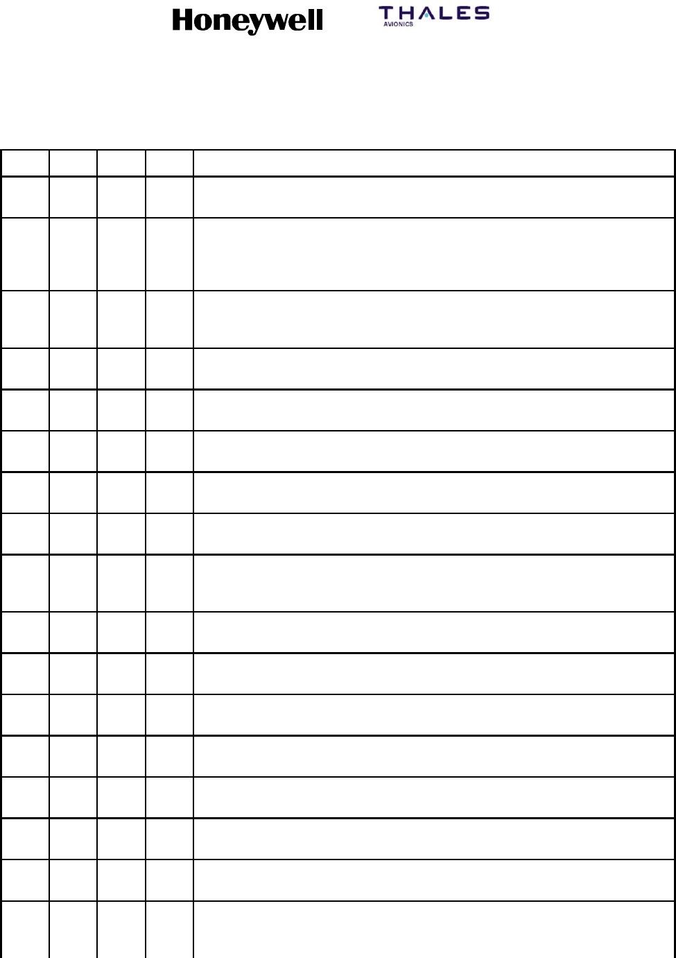
SYSTEM DESCRIPTION, INSTALLATION, AND MAINTENANCE MANUAL
MCS--4200/7200 Multi--Channel SATCOM System
23--20--35 15 Jul 2006
Honeywell International Inc. Do not copy without express permission of Honeywell.
Page D--12
Table D--3. SLCV Description for HSD ISDN Call Terminations (cont)
S DescriptionCVL
1 4 5 1 LES is rejecting the call because an appropriate terrestrial circuit is not
currently available at this specific LES.
1 4 5 2 LES is rejecting the call because an appropriate channel unit and associated
terrestrial circuit are not currently available at this LES. [This “cause” is only
utilized when there is a permanent “one--to--one” connection between
appropriate channel units and their terrestrial circuits].
1 5 0 2 (Spot Beam Handover): LES is ready to make the transition from the current
beam to the next beam and is clearing the call session in the current beam
(normal clear).
1 5 5 1 LES is rejecting the call because an appropriate satellite channel is not
currently available at this specific LES.
1 5 8 1 LES is rejecting the call because the requested service is not provided by
this specific LES.
1 5 9 1 LES is rejecting the call because the requested service is temporarily not
available at this specific LES.
1 5 A 1 LES is rejecting the call because the specified MES is not authorized for any
service at this specific LES.
1 5 A 2 LES is rejecting the call because the specified MES is not authorized to use
specific requested service via this specific LES.
1 5 A 4 LES is clearing the call because the data received from the MES in the
“authentication reply” message (type B6H) has been declared “invalid” by
the LES authentication process.
1 5 A 5 LES is rejecting the call because the specified PID is not authorized for any
service at this specific LES.
1 5 A 6 LES is rejecting the call because the specified PID is not authorized to use
specific requested service via this specific LES.
1 5 A 7 LES is clearing the call because the service address received from the MES
is not authorized for the requested priority.
1 5 B 1 LES is rejecting or clearing the call for a reason which is not covered by any
of the currently defined “Cause” events.
1 5 C 1 LES is rejecting the call because an appropriate “Channel Assignment”
message has not been received by the LES within the allowed time limit.
1 5 C 2 LES is clearing the call because the “service address” information has not
been received by the LES within the allowed time limit.
1 5 C 3 LES is clearing the call because a “Scrambling Vector” message (type 8DH)
has not been received by the LES within the allowed time limit.
1 5 C 4 LES is clearing the call because neither the “service address” information
nor a “Scrambling Vector” message (type 8DH ) has been received by the
LES within the allowed time limit.
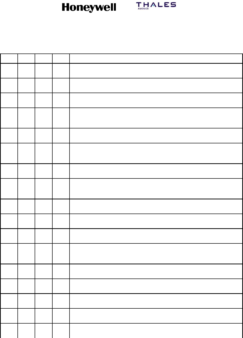
SYSTEM DESCRIPTION, INSTALLATION, AND MAINTENANCE MANUAL
MCS--4200/7200 Multi--Channel SATCOM System
23--20--35 15 Jul 2006
Honeywell International Inc. Do not copy without express permission of Honeywell.
Page D--13
Table D--3. SLCV Description for HSD ISDN Call Terminations (cont)
S DescriptionCVL
1 5 C 7 LES is clearing the call because a “MES Connect” message (type 99H) has
not been received by the LES within the allowed time limit.
1 5 C 9 LES is clearing the call because a “authentication reply” message (type
B6H) has not been received by the LES within the allowed time limit.
1 5 C A LES is clearing the call because a “notification acknowledge” message (type
BAH ) has not been received by the LES within the allowed time limit.
1 5 C B LES is clearing the call because the request sequence number contained in
the received “notification acknowledge” message (type BA) is not valid (i.e.
either not ‘0’ or not the next value in the sequence).
1 5 C C (Spot Beam Handover): LES is terminating the procedure because it did not
receive a response to the Handover Request from the NCS.
1 5 C D (Spot Beam Handover): LES is clearing the call session in the next beam
because the MES did not indicate that it was ready to make the transition
(possibly because the MES did not receive the Channel Assignment).
1 5 D 1 LES is rejecting the call because the “Channel Assignment” message
received from the NCS contains inappropriate or conflicting information.
1 5 D 2 LES is clearing this MES ID and channel number in the busy lists at LES
and NCS because a new call to/from this MES is being set--up (and thus
any previous call to/from this MES must have cleared).
1 5 E 1 LES is attempting to clear an MES which has sent an SCPC channel
release message but is found still to be transmitting 5.12 seconds later.
1 6 5 1 LES is rejecting the call because an appropriate channel unit is not currently
available at this specific LES.
1 6 6 1 LES is clearing the call because of an interruption in reception of the MES
carrier exceeding the allowed time limit.
1 6 C 2 LES is clearing the call because an appropriate SCPC MES carrier has not
been received by the LES (at the commencement of the call) within the
allowed time limit.
1 6 C 3 (Spot Beam Handover): LES is clearing the call session in the next beam
because the LES did not detect the MESH carrier on the new frequency.
1 7 9 1 LES is clearing the call because of a malfunction in the authentication
checking database or in the communications links thereto.
1 8 1 1 NCS is rejecting the call because the specified MES ID is in the “MES busy”
list at the NCS.
1 8 1 2 NCS is rejecting the call because the specified MES is busy with an IPDS
call at the NCS.
1 8 5 1 NCS is rejecting the call because an appropriate SCPC channel is not
currently available.
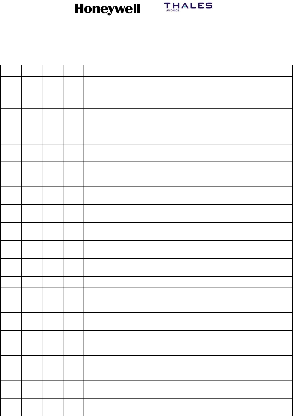
SYSTEM DESCRIPTION, INSTALLATION, AND MAINTENANCE MANUAL
MCS--4200/7200 Multi--Channel SATCOM System
23--20--35 15 Jul 2006
Honeywell International Inc. Do not copy without express permission of Honeywell.
Page D--14
Table D--3. SLCV Description for HSD ISDN Call Terminations (cont)
S DescriptionCVL
1 8 5 2 NCS is rejecting the call because no SCPC channel exists at the NCS which
matches the contents of the Channel Parameters, Service Nature, Service
Type, MES Category, Spot Beam ID and Priority fields contained in the
Request for Channel Assignment.
1 8 5 3 NCS is rejecting the call because no SCPC channel is currently available for
the specified leasemarked MES.
1 8 5 4 NCS is rejecting the call because the MES is outside the spot beam
coverage area.
1 8 5 5 NCS is rejecting the call because an appropriate SCPC channel is not
currently available and channel pre--emption failed.
1 8 5 6 NCS is rejecting the call because the requested spot beam indicates failed
spot beam selection (“FF” ) and an appropriate global SCPC channel is not
currently available.
1 8 5 7 (Spot Beam Handover) NCS is rejecting the Handover Request because an
appropriate SCPC channel is not available in the next beam.
1 8 A 1 NCS is rejecting the call because the specified MES ID was not found in the
“Forward and Return MES ID” cross--reference table.
1 8 A 2 NCS is rejecting the call because the specified MES is not authorized for
any service (except for Distress calls) at the NCS.
1 8 A 3 NCS is rejecting the call because the specified LES is not authorized for the
requested service at the NCS.
1 8 B 1 NCS is rejecting or clearing the call for a reason which is not covered by any
of the currently defined “Cause” events.
1 8 B 2 NCS is rejecting the call because the requested service variant is invalid.
1 8 C 1 NCS is rejecting the call because no message was received from the
specified MES (in reaction to a Call Announcement message) within the
allowed time limit.
1 8 C 3 NCS is rejecting the call because the specified MES was busy and the MES
pre--emption failed (i.e. no response within the allowed time limit).
1 8 D 1 NCS is rejecting the call because the Request for Call Announcement or
Request for Channel Assignment contains invalid or inappropriate
information.
1 8 E 1 NCS is rejecting the call because the specified MES ID is in the “MES busy”
list at the NCS, and is listed as being busy with a call through the same LES
as that now requesting a “call announcement” addressed to that MES.
1 8 E 2 NCS is rejecting the call because the specified MES is busy with an IPDS
call through the same LES which is requesting the call announcement.
1 F 0 1 LES is clearing the call because of the receipt of “on--hook” signalling from
the relevant terrestrial circuit (i.e., normal clearing).
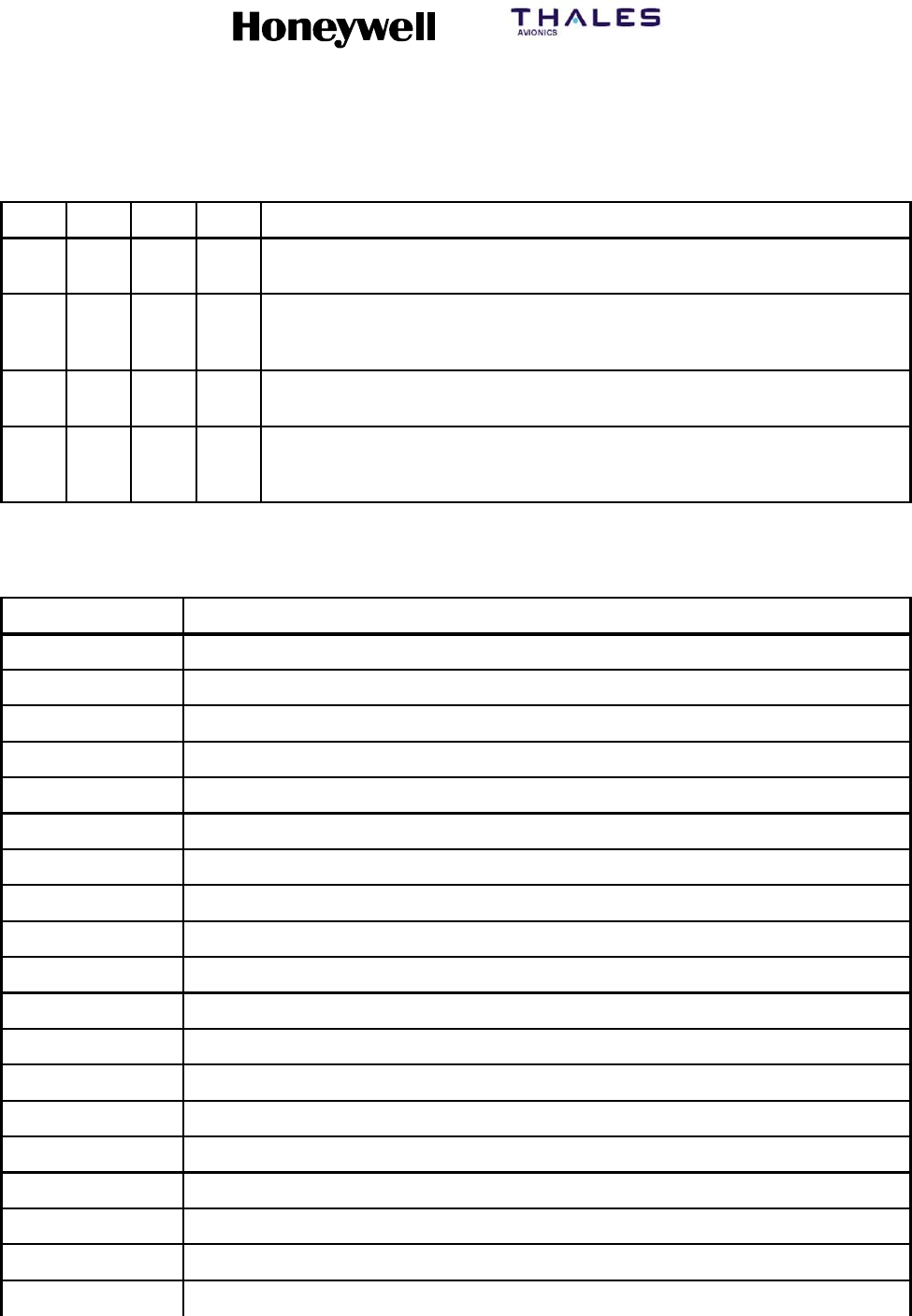
SYSTEM DESCRIPTION, INSTALLATION, AND MAINTENANCE MANUAL
MCS--4200/7200 Multi--Channel SATCOM System
23--20--35 15 Jul 2006
Honeywell International Inc. Do not copy without express permission of Honeywell.
Page D--15
Table D--3. SLCV Description for HSD ISDN Call Terminations (cont)
S DescriptionCVL
1 F 1 1 LES is clearing the call because the terrestrial called party is engaged
(busy).
1 F 2 1 LES is clearing the call because appropriate “off--hook” signalling from the
terrestrial called party has not been received by the LES within the allowed
time limit.
1 F 6 1 LES is clearing the call because of the detection of a failure in the relevant
terrestrial circuit.
1 F 6 2 The LES is clearing the call because the terrestrial calling party or the
terrestrial network has cleared the call before the “MES connect” message
has been received by the LES.
Table D--4. Detailed Codes
ID Description
0x00 Default value
0x01 Channel out of range
0x04 MES time--out
0x05 Incoming call in progress
0x09 Call spacing restriction not fulfilled
0x0B Timeout on phone number dialing
0x0E Invalid Ocean Region
0x10 Invalid Telephone Interface type
0x11 The terminal id already in use
0x22 Min--op not achieved
0x24 HSU equipment failure
0x30 Cooperative Preempt: High Priority Call
0x31 Cooperative Preempt: Ocean Region Handover
0x32 Cooperative Preempt: System Failure
0x33 Cooperative Preempt: No Power Available
0x34 Cooperative Preempt: Not Logged On
0x35 Cooperative Preempt: GNSS Frequency Check Error
0x36 Cooperative Preempt: Spare
0x37 Cooperative Preempt: Invalid Parameter
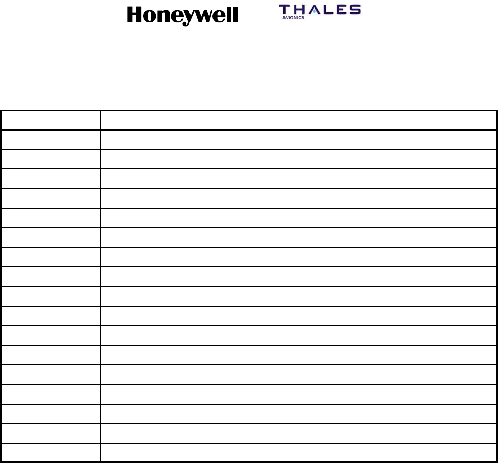
SYSTEM DESCRIPTION, INSTALLATION, AND MAINTENANCE MANUAL
MCS--4200/7200 Multi--Channel SATCOM System
23--20--35 15 Jul 2006
Honeywell International Inc. Do not copy without express permission of Honeywell.
Page D--16
Table D--4. Detailed Codes (cont)
ID Description
0x40 Ruthless Preempt: High Priority Call
0x41 Ruthless Preempt: Ocean Region Handover
0x42 Ruthless Preempt: System Failure
0x43 Ruthless Preempt: No Power Available
0x44 Ruthless Preempt: Not Logged On
0x45 Ruthless Preempt: GNSS Frequency Check Error
0x46 Ruthless Preempt: Spare
0x47 Ruthless Preempt: Invalid Parameter
0x50 EIRP Request Reject: High Priority Call
0x51 EIRP Request Reject: Ocean Region Handover
0x52 EIRP Request Reject: System Failure
0x53 EIRP Request Reject: No Power Available
0x54 EIRP Request Reject: Not Logged On
0x55 Power Not Available (prior to Package 6.0)
0x55 EIRP Request Reject: GNSS Frequency Check Error (Package 6.0 and subsequent)
0x56 EIRP Request Reject: Spare
0x57 EIRP Request Reject: Invalid Parameter

SYSTEM DESCRIPTION, INSTALLATION, AND MAINTENANCE MANUAL
MCS--4200/7200 Multi--Channel SATCOM System
23--20--35 15 Jul 2006
Honeywell International Inc. Do not copy without express permission of Honeywell.
Page E--1
APPENDIX E
MESSAGING
1. PPPoE Messaging
A. General
(1) The following subsections define the format and services for the PPPoE discovery
packets as defined in RFC 2516.
B. PPPoE Active Discovery Offer (PADO)
(1) The HSU will respond to PPPoE Active Discovery Initiation (PADI) packets in
accordance with RFC 2516. If the requested service in not available, the HSU will not
provide a PADO response.
(2) The HSU will support service names of length less than or equal to 64 characters.
The conditions for the PADO response and the PADO content are as specified in
Table E--1.
Table E--1. PADO Services
PADI Service Name PADO Response Controlling Condition
No service name tag Null terminated, or PacketData, or
Swift64
If all services are available or if
SwiftBroadband PS services are
available or if MPDS services are
available. This PADI may be used
as a status poll from a server.
PacketData PacketData SwiftBroadband PS services or
MPDS services are available on at
least one channel.
BGAN BGAN SwiftBroadband PS services
available on at least one channel.
BGAN--1 BGAN--1 SwiftBroadband PS services
available on Channel Card 1.
BGAN--2 BGAN--2 SwiftBroadband CS and PS
services available on Channel
Card 2.
MPDS MPDS MPDS service available on at
least one channel.
MPDS--1 MPDS--1 MPDS service available on at
least on channel of Channel Card
1 (HSU channel 1 or 2).
MPDS--2 MPDS--2 MPDS service available on at
least on channel of Channel Card
2 (HSU channel 3 or 4).
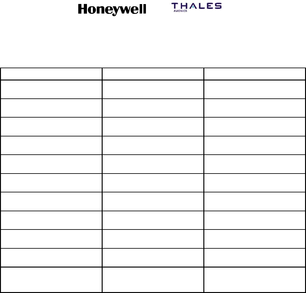
SYSTEM DESCRIPTION, INSTALLATION, AND MAINTENANCE MANUAL
MCS--4200/7200 Multi--Channel SATCOM System
23--20--35 15 Jul 2006
Honeywell International Inc. Do not copy without express permission of Honeywell.
Page E--2
Table E--1. PADO Services (cont)
PADI Service Name Controlling ConditionPADO Response
MPDS--1A MPDS--1A MPDS service available on HSU
Channel 1.
MPDS--1B MPDS--1B MPDS service available on HSU
Channel 2.
MPDS--2A MPDS--2A MPDS service available on HSU
Channel 3.
MPDS--2B MPDS--2B MPDS service available on HSU
Channel 4.
MPDS--C1 MPDS--C1 MPDS service is available on HSU
Channel 1.
MPDS--C2 MPDS--C2 MPDS service is available on HSU
Channel 2.
MPDS--C3 MPDS--C3 MPDS service is available on HSU
Channel 3.
MPDS--C4 MPDS--C4 MPDS service is available on HSU
Channel 4.
123 123 MPDS service available on at
least one channel.
28# 28# M--ISDN service is available on at
least one channel.
Numeric digits (See below) Numeric digits (See below) SwiftBroadband CS or M--ISDN
service available on at least one
channel.
(3) The PADI response to a series of numeric digits is detailed in the following:
(a) Definitions:
•“Dialed”digitsaredefinedastheset{0,1,2,3,4,5,6,7,8,9,*}
•“Dial Termination” characters are defined as the set { # (octothorp, ASCII 23x),
: (colon, ASCII 3Ax)}
•“Unrecognized” characters are defined as the rest of the ASCII character set.
•“Filtered Service Name” is the service--name with unrecognized characters
removed, stopping at (but not including) the first dial termination character, if
any.
(b) If the PADI service name contains up to the first dial termination character, no
unrecognized characters, and consists of two (2) or more dialed digits, and if
SwiftBroadband CS or Swift64 M--ISDN service is available on a channel, the
HSU will respond with a PADO echoing the service name.

SYSTEM DESCRIPTION, INSTALLATION, AND MAINTENANCE MANUAL
MCS--4200/7200 Multi--Channel SATCOM System
23--20--35 15 Jul 2006
Honeywell International Inc. Do not copy without express permission of Honeywell.
Page E--3
(c) If the PADI filtered service name consists of seven (7) or more dialed digits, and
if SwiftBroadband CS or Swift64 M--ISDN service is available on a channel, the
HSU will respond with a PADO echoing the service name.
(d) If the PADI service name consists of the specific string “123”, and if MPDS
service is available on any available channel, the HSU will respond with a PADO
echoing the service name.
C. PPPoE Active Discovery Request (PADR)
(1) The HSU will respond to PPPoE Active Discovery Request (PADR) packets in
accordance with RFC 2516. If the requested service in not available, the HSU will not
initiate a PPP session and will send a PPPoE active discovery session confirmation
(PADS) packet with a service--name error tag.
(2) The HSU will support service names of length less than or equal to 64 characters.
(3) The HSU response to the PADR packet is as specified in Table E--2.
Table E--2. PADR Services
PADR Service
Name HSU response
No service name
tag
If SwiftBroadband services are available, a PS session is initiated using the PDP
parameters provided by the SDU. If SwiftBroadband services are not available and
MPDS services are available, an MPDS session will be initiated.
PacketData If SwiftBroadband services are available, a PS session is initiated using the PDP
parameters provided by the SDU. If SwiftBroadband services are not available and
MPDS services are available, an MPDS session will be initiated.
BGAN A SwiftBroadband PS session is initiated on an available channel card.
BGAN--1 A SwiftBroadband PS session is initiated on Channel Card 1.
BGAN--2 A SwiftBroadband PS session is initiated on Channel Card 2.
MPDS An MPDS session is initiated on an available channel.
MPDS --1 An MPDS session is initiated on Channel Card 1 (HSU channel 1 or 2).
MPDS --2 An MPDS session is initiated on Channel Card 2 (HSU channel 3 or 4).
MPDS--1A MPDS session is initiated on HSU Channel 1.
MPDS--1B MPDS session is initiated on HSU Channel 2.
MPDS--2A MPDS session is initiated on HSU Channel 3.
MPDS--2B MPDS session is initiated on HSU Channel 4.
MPDS--C1 MPDS session is initiated on HSU Channel 1.
MPDS--C2 MPDS session is initiated on HSU Channel 2.
MPDS--C3 MPDS session is initiated on HSU Channel 3.
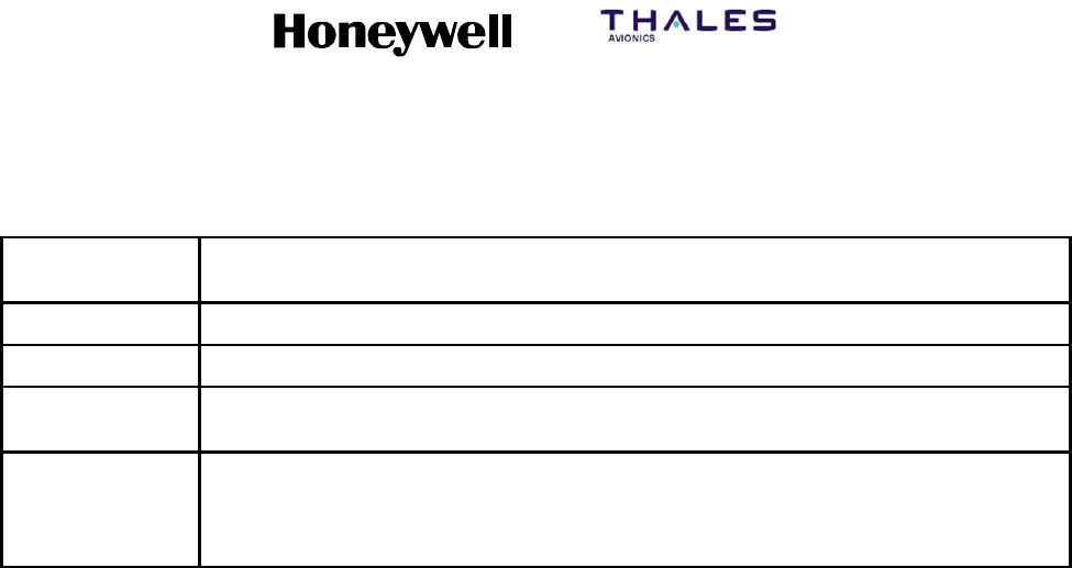
SYSTEM DESCRIPTION, INSTALLATION, AND MAINTENANCE MANUAL
MCS--4200/7200 Multi--Channel SATCOM System
23--20--35 15 Jul 2006
Honeywell International Inc. Do not copy without express permission of Honeywell.
Page E--4
Table E--2. PADR Services (cont)
PADR Service
Name HSU response
MPDS--C4 MPDS session is initiated on HSU Channel 4.
123 MPDS session is initiated on any available channel.
28# M--ISDN 64k UDI session initiated to called party number “28” on any available
channel.
Numeric digits
(See below)
If SwiftBroadband services are available, a CS session is initiated on any available
channel to the called party number defined below. If SwiftBroadband services are not
available and M--ISDN service is available, a 64k UDI session is initiated on any
available channel to the called party number defined below.
(4) The HSU will determine the called party number from the PADR service name as
detailed in the following:
(a) Definitions:
•“Dialed”digitsaredefinedastheset{0,1,2,3,4,5,6,7,8,9,*}
•“Dial Termination” characters are defined as the set { # (octothorp, ASCII 23x),
: (colon, ASCII 3Ax)}
•“Unrecognized” characters are defined as the rest of the ASCII character set.
•“Filtered Service Name” is the service--name with unrecognized characters
removed, stopping at (but not including) the first dial termination character, if
any.
(b) If the PADR service name contains up to the first dial termination character, no
unrecognized characters, and consists of two (2) or more “dialed” digits, and if
SwiftBroadband CS service is available, the HSU will initiate a SwiftBroadband
CS session on an available channel using the service name as the called party
number.
(c) If the PADR service name contains up to the first dial termination character, no
unrecognized characters, and consists of two (2) or more “dialed” digits, and
SwiftBroadband CS service is not available, and Swift64 M--ISDN is available,
the HSU will initiate a M--ISDN 64k UDI session on an available channel using
the service name as the called party number.
(d) If the PADR filtered service name contains up to seven (7) or more “dialed” digits,
and if SwiftBroadband CS service is available, the HSU will initiate a
SwiftBroadband CS session on an available channel using the filtered service
name as the called party number.
(e) If the PADR filtered service name contains up to seven (7) or more “dialed” digits,
and SwiftBroadband CS service is not available, and Swift64 M--ISDN is
available, the HSU will initiate an M--ISDN 64k UDI session on an available
channel using the filtered service name as the called party number.

SYSTEM DESCRIPTION, INSTALLATION, AND MAINTENANCE MANUAL
MCS--4200/7200 Multi--Channel SATCOM System
23--20--35 15 Jul 2006
Honeywell International Inc. Do not copy without express permission of Honeywell.
Page E--5
(f) If the PADR service name consists of the specific string “123”, and if MPDS
service is available on any channel, the HSU will initiate an MPDS session on an
available channel.
D. PPPoE Active Discovery Session--Confirmation (PADS)
(1) The HSU will provide PPPoE Active Discovery Session--Confirmation (PADS) packets
in response to PADR packets in accordance with RFC 2516.
(2) If the requested service in not available, the HSU will not initiate a PPP session and
will send a PPPoE active discovery session confirmation (PADS) packet with a
service--name error tag as specified in Table E--3.
(3) The HSU may provide a PADS response prior to the establishment of the
over--the--satellite call connection.
TableE--3. ServiceNameError
PADR Service Name Service--Name Error Tag
No Service--Name tag Missing Service--Name
No Service--Name tag
(and default service is disabled by a HSU
configuration item)
Default service disabled
Service--Name not recognized
(not from set of Table E--2)
Unrecognized service
Requested Service--Name is disabled or not
available
Service disabled or unavailable
Requested Service--Name became unavailable after
PADR received, but before PPP session established
Unable to reserve the channel
E. PPPoE Active Discovery Termination (PADT)
(1) The HSU will provide a PPPoE Active Discovery Termination (PADT) packet in
response to termination of the PPPoE session.
(2) The PPPoE session may be terminated by the HSU or by a PADT from the host.
(3) The HSU will send periodic Echo--Request packets to the host to assess continued
connectivity.
(4) The HSU will generate a Generic Error tag upon termination of every session,
including those that terminate normally. The Generic--Error tag is of the following
format:

SYSTEM DESCRIPTION, INSTALLATION, AND MAINTENANCE MANUAL
MCS--4200/7200 Multi--Channel SATCOM System
23--20--35 15 Jul 2006
Honeywell International Inc. Do not copy without express permission of Honeywell.
Page E--6
(a) SLCV – nnnn/dddd: SLCV_cause_string [detailed_cause_string] Where:
•nnnn is the Inmarsat SLCV termination code as defined in Table E--4.
•dddd is the detailed cause code defined in Table E--4.
•SLCV_cause_string is the (modified) Inmarsat standard cause code
wording defined in Table E--4.
•detailed_cause_string is extended cause description as defined in
Table E--4.
(5) The HSU will generate an AC--System--Error tag upon termination of every session,
including those that terminate normally. The AC--System--Error tag is as defined
below.
(a) If the PPPoE session was a Swift64 64k UDI session, the AC--System--Error tag
will be of the following format:
1Q850 – qqq: Q.850_string Where:
•qqq is the ISDN Q.850 cause code defined in Table E--5.
•Q.850_string is the Q.850 cause string defined in Table E--5.
(b) If the PPPoE session was a Swift64 MPDS session, the AC--System--Error tag
will be of the following format:
1MPDS – mmm: +WQ_cause_string defined in Table E--6. Where:
•qqq is the MPDS AT +WQ cause number defined in Table E--6.
•+WQ_cause_string is the MPDS AT +WQ cause string defined in
Table E--6.
(c) If the PPPoE session was a SwiftBroadband PS session, the AC--System--Error
tag will be of the following format:
1BGAN – bbb: TBD Where:
•bbb and TBD are not specified.
Table E--4. SLCV Cause Codes and Strings
SLCV dddd SLCV cause string Detailed cause string Comments
1001 0000 call cleared by MES terminal
1011 0000 call failed, MES terminal busy
1012 0000 call cleared, MES terminal
busy
1021 0000 call failed, MES time--out (no
answer)
1081 0000 call failed, MES terminal not
installed

SYSTEM DESCRIPTION, INSTALLATION, AND MAINTENANCE MANUAL
MCS--4200/7200 Multi--Channel SATCOM System
23--20--35 15 Jul 2006
Honeywell International Inc. Do not copy without express permission of Honeywell.
Page E--7
Table E--4. SLCV Cause Codes and Strings (cont)
SLCV CommentsDetailed cause stringSLCV cause stringdddd
1091 0000 call failed, MES terminal
out--of--service
1092 0000 call cleared, MES terminal
out--of--service
1141 0000 MES preempted clear by
higher priority call
1142 0000 MES preempted fixed call by
higher priority call
1143 0000 offered call cleared,
pre--empted at MES
1144 0000 call cleared, MES initiated
preemption
1145 0000 attempted call cleared,
pre--empted at MES
1146 0000 attempted call abandoned by
MES terminal
1191 0000 MES outside spot beam
11A0 0000 call cleared, credit card not
accepted
11D1 0000 call failed, LES service call
type Incorrect
11D2 0000 call failed, insufficient digits in
service address
11D3 0000 call failed, invalid service
address
11D4 0000 call cleared, credit card data
information invalid
11D5 0000 call cleared, invalid country
code
11D6 0000 call cleared, PID information is
not consistent
11D7 0000 call rejected, invalid service for
pri. 1 or 2 call
11D8 0000 call cleared, dialed number not
2 or 3 digits for pri. 1 or 2 call
11E0 0000 call cleared, invalid credit card
PIN at this LES

SYSTEM DESCRIPTION, INSTALLATION, AND MAINTENANCE MANUAL
MCS--4200/7200 Multi--Channel SATCOM System
23--20--35 15 Jul 2006
Honeywell International Inc. Do not copy without express permission of Honeywell.
Page E--8
Table E--4. SLCV Cause Codes and Strings (cont)
SLCV CommentsDetailed cause stringSLCV cause stringdddd
11E1 0000 call cleared, too many invalid
credit card call attempts
1202 0000 handover, MES ready
1262 0000 MES distress timeout
1281 0000 call failed, MES cannot accept
1291 0000 call failed, MES cannot accept
at present
1291 0034 call failed, MES cannot accept
at present
Call cleared, SDU not logged
On
Cooperative Preempt:
Not Logged On
1291 0035 call failed, MES cannot accept
at present
Call cleared, GNSS frequency
check error
Cooperative Preempt:
GNSS Frequency
Check Error
1291 0044 call failed, MES cannot accept
at present
Call cleared, SDU not logged
On
Ruthless Preempt:
Not Logged On
1291 0045 call failed, MES cannot accept
at present
Ruthless Preempt: GNSS
Frequency Check Error
Call cleared, GNSS
frequency check error
1291 0054 call failed, MES cannot accept
at present
EIRP Request rejected due to:
Not Logged On
Call rejected, SDU not
logged On
1291 0055 call failed, MES cannot accept
at present
Call rejected, GNSS
frequency check error
EIRP Request
rejected due to:
GNSS Frequency
Check Error
12B1 0000 call cleared by MES for
unspecified reason
12B1 0024 call cleared by MES for
unspecified reason
HSU Equipment Failure
12B1 0032 call cleared by MES for
unspecified reason
Call cleared, SDU reporting
system failure
Cooperative Preempt:
System Failure
12B1 0036 call cleared by MES for
unspecified reason
Call cleared, pre--empted by
SDU for undeclared reason
Cooperative Preempt:
Spare
12B1 0037 call cleared by MES for
unspecified reason
Call cleared, pre--empted by
SDU for invalid parameter
Cooperative Preempt:
Invalid Parameter
12B1 0042 call cleared by MES for
unspecified reason
Call cleared, SDU reporting
system failure
Ruthless Preempt:
System Failure
12B1 0046 call cleared by MES for
unspecified reason
Call cleared, pre--empted by
SDU for undeclared reason
Ruthless Preempt:
Spare
12B1 0047 call cleared by MES for
unspecified reason
Call cleared, pre--empted by
SDU for invalid parameter
Ruthless Preempt:
Invalid Parameter

SYSTEM DESCRIPTION, INSTALLATION, AND MAINTENANCE MANUAL
MCS--4200/7200 Multi--Channel SATCOM System
23--20--35 15 Jul 2006
Honeywell International Inc. Do not copy without express permission of Honeywell.
Page E--9
Table E--4. SLCV Cause Codes and Strings (cont)
SLCV CommentsDetailed cause stringSLCV cause stringdddd
12B1 0052 call cleared by MES for
unspecified reason
Call rejected, SDU reporting
system failure
EIRP Request
rejected due to:
System Failure
12B1 0056 call cleared by MES for
unspecified reason
Call rejected, pre--empted by
SDU for undeclared reason
EIRP Request
rejected due to: Spare
12B1 0057 call cleared by MES for
unspecified reason
Call rejected, pre--empted by
SDU for invalid parameter
EIRP Request
rejected due to:
Invalid Parameter
12C2 0000 call cleared, no credit card
valid message received
12C3 0000 call failed, MES time--out (no
terrestrial answer)
12C4 0000 call cleared, authentication
query not received
12C5 0000 call cleared, MES missing sup
service SU
12C6 0000 call cleared, MES missing sup
service2SU
12C7 0000 call cleared, MES missing
SCPC channel release SU
sup service
12C8 0000 handover failed, LES not
detected
12D1 0000 call failed, spot beam data
invalid
12D2 0000 call failed, invalid scrambling
vector
1351 0000 call cleared, insufficient free
memory
1361 0000 call cleared by MES cable
unwrap
1362 0000 call cleared, long interruption
in reception at MES
1363 0000 MES secondary clear due to
repoint OR
1363 0031 MES secondary clear due to
repoint OR
Call cleared, SDU re--pointing
antenna to different Ocean
Region
Cooperative Preempt:
Ocean Region
Handover

SYSTEM DESCRIPTION, INSTALLATION, AND MAINTENANCE MANUAL
MCS--4200/7200 Multi--Channel SATCOM System
23--20--35 15 Jul 2006
Honeywell International Inc. Do not copy without express permission of Honeywell.
Page E--10
Table E--4. SLCV Cause Codes and Strings (cont)
SLCV CommentsDetailed cause stringSLCV cause stringdddd
1363 0041 MES secondary clear due to
repoint OR
Call cleared, SDU re--pointing
antenna to different Ocean
Region
Ruthless Preempt:
Ocean Region
Handover
1363 0051 MES secondary clear due to
repoint OR
Call rejected, SDU re--pointing
antenna to different Ocean
Region
EIRP Request
rejected due to:
Ocean Region
Handover
1391 0000 call cleared, traveled distance
exceeds 700km
1392 0000 call cleared, spot beam
transition
1393 0000 call cleared, cooperative mode
1393 0030 call cleared, cooperative mode Call cleared, pre--empted by
higher priority call
Cooperative Preempt:
High Priority Call
1393 0033 call cleared, cooperative mode Call cleared, no power
available from SDU
Cooperative Preempt:
No Power Available
1393 0040 call cleared, cooperative mode Call cleared, pre--empted by
higher priority call
Ruthless Preempt:
High Priority Call
1393 0043 call cleared, cooperative mode Call cleared, no power
available from SDU
Ruthless Preempt: No
Power Available
1393 0044 call cleared, cooperative mode Channel cleared, SDU not
logged on
Ruthless Preempt:
Not Logged On
1393 0050 call cleared, cooperative mode Call rejected, pre--empted by
higher priority call
EIRP Request
rejected due to: High
Priority Call
1393 0053 call cleared, cooperative mode Call rejected, no power
available from SDU
EIRP Request
rejected due to: No
Power Available
1451 0000 call failed, terrestrial circuits
congested
1452 0000 call failed, LES congested (no
channel and no circuit)
1502 0000 spotbeam handover, LES
ready, normal clear
1551 0000 call failed, LES congested (no
channel)
1581 0000 call failed, service not
provided at this LES

SYSTEM DESCRIPTION, INSTALLATION, AND MAINTENANCE MANUAL
MCS--4200/7200 Multi--Channel SATCOM System
23--20--35 15 Jul 2006
Honeywell International Inc. Do not copy without express permission of Honeywell.
Page E--11
Table E--4. SLCV Cause Codes and Strings (cont)
SLCV CommentsDetailed cause stringSLCV cause stringdddd
1591 0000 call failed, service temporarily
not available at this LES
1592 0000 call cleared, credit card type
not supported
15A1 0000 call failed, MES not authorised
at this LES
15A2 0000 call failed, service not
authorised at this LES
15A3 0000 call cleared, credit card not
authorised
15A4 0000 call cleared, authentication
reply invalid
15A5 0000 call failed, PID not authorised
for any service
15A6 0000 call failed, PID not authorised
for requested service
15B1 0000 call cleared by LES for
unspecified reason
15C1 0000 call failed, no channel
assignment from LES
15C2 0000 call failed, LES time--out (no
service address)
15C3 0000 call failed, LES time--out (no
scrambling vector)
15C4 0000 call failed, no service address
and no scrambling vector
15C5 0000 call cleared, incomplete credit
card data information
15C7 0000 call failed, LES time--out (no
MES connect)
15C9 0000 call cleared, no authentication
reply
15CA 0000 call cleared, notification ack
not received
15CB 0000 call cleared, invalid sequence
number in notification ack
15CC 0000 handover failed, no response
to request

SYSTEM DESCRIPTION, INSTALLATION, AND MAINTENANCE MANUAL
MCS--4200/7200 Multi--Channel SATCOM System
23--20--35 15 Jul 2006
Honeywell International Inc. Do not copy without express permission of Honeywell.
Page E--12
Table E--4. SLCV Cause Codes and Strings (cont)
SLCV CommentsDetailed cause stringSLCV cause stringdddd
15CD 0000 handover failed, MES not
ready
15D1 0000 call failed, LES time--out
(invalid assignment)
15D2 0000 LES MES already busy
15E1 0000 call cleared but MES still
transmitting (FAULT)
1651 0000 call failed, LES congested (no
channel unit)
1661 0000 call failed, long interruption in
reception at LES
1662 0000 LES long term blockage of
SCPC MES
16C2 0000 LES missing MES SCPC
16C3 0000 handover failed, MES not
detected
1790 0000 call cleared, failure credit card
validation process
1791 0000 call cleared, failure
authentication process
1811 0000 NCS MES ID busy
1812 0000 NCS MES ID busy MPDS
1813 0000 Call waiting request rejected,
MES not accepted call
1814 0000 Call waiting request rejected,
RLES shows MES busy
1841 0000 call cleared, NCS initiated
preemption for incoming pri.1
call
1842 0000 call cleared, NCS initiated
preemption for incoming pri.2
call
1843 0000 call cleared, NCS initiated
preemption for incoming pri.3
call
1844 0000 call cleared, NCS initiated
preemption

SYSTEM DESCRIPTION, INSTALLATION, AND MAINTENANCE MANUAL
MCS--4200/7200 Multi--Channel SATCOM System
23--20--35 15 Jul 2006
Honeywell International Inc. Do not copy without express permission of Honeywell.
Page E--13
Table E--4. SLCV Cause Codes and Strings (cont)
SLCV CommentsDetailed cause stringSLCV cause stringdddd
1851 0000 call failed, satellite congestion
NCS reject no SCPC available
1852 0000 call failed, satellite congestion
NCS reject SCPC does not
match request
1853 0000 call failed, lease channel
congestion
1854 0000 call failed, MES outside spot
beam coverage area
1855 0000 call rejected, preemption
failed, no channel available
1856 0000 call rejected, spot beam
selection failed
1857 0000 handover failed, channel not
available
185A 0000 NCS Reject Lease--marked
MES----NoMatchingSCPC
channel
18A1 0000 NCS MES ID not found
18A2 0000 call failed, MES not authorised
18A3 0000 call failed, LES not authorised
18B1 0000 call failed by NCS for
unspecified reason
18B2 0000 call rejected, invalid service
requested
18C1 0000 NCS MES burst missing
18C3 0000 NCS MES busy preemption
failed
18D1 0000 call failed, invalid call request
18E1 0000 NCS MES busy already
18E2 0000 NCS MES busy already
MPDS
1D61 0000 Call wait failed, fixed line hung
up
1F01 0000 call cleared by terrestrial
circuit

SYSTEM DESCRIPTION, INSTALLATION, AND MAINTENANCE MANUAL
MCS--4200/7200 Multi--Channel SATCOM System
23--20--35 15 Jul 2006
Honeywell International Inc. Do not copy without express permission of Honeywell.
Page E--14
Table E--4. SLCV Cause Codes and Strings (cont)
SLCV CommentsDetailed cause stringSLCV cause stringdddd
1F11 0000 call failed, terrestrial party
busy
1F21 0000 call failed, LES time--out (no
answer)
1F61 0000 call failed, terrestrial circuit
failure
1F62 0000 call failed, early clear by
terrestrial circuit
0000 0000 MPDS channel cleared No Inmarsat SLCV for
termination of MPDS
session
0000 0064 MPDS channel cleared MPDS Port error code 100
401
0000 01F4 MPDS channel cleared Unknown Error 500
0000 01F5 MPDS channel cleared LES Access Code does not
support MPDS
0000 01F6 MPDS channel cleared Network does not recognise
Mobile ID
0000 01F7 MPDS channel cleared Network does not recognise
Sim Card
0000 01F8 MPDS channel cleared Authentication Failed to
Complete
0000 01F9 MPDS channel cleared Authentication Failure
0000 01FA MPDS channel cleared Authorisation Failure
0000 01FB MPDS channel cleared Authorisation Failure -- Mobile
Barred
0000 01FC MPDS channel cleared Authorisation Failure -- Mobile
Barred on this LES Access
Code
0000 01FD MPDS channel cleared Authorisation Failure -- SIM
Card Barred on this LES
Access Code
0000 01FE MPDS channel cleared Authorisation Failure --
Temporarily Unable to Accept
Credit Cards
0000 01FF MPDS channel cleared Authorisation Failure -- Unable
to Accept Credit Cards

SYSTEM DESCRIPTION, INSTALLATION, AND MAINTENANCE MANUAL
MCS--4200/7200 Multi--Channel SATCOM System
23--20--35 15 Jul 2006
Honeywell International Inc. Do not copy without express permission of Honeywell.
Page E--15
Table E--4. SLCV Cause Codes and Strings (cont)
SLCV CommentsDetailed cause stringSLCV cause stringdddd
0000 0200 MPDS channel cleared Authorisation Failure -- Credit
Card Refused
0000 0201 MPDS channel cleared Authorisation Failure -- This
Service not Allowed
0000 0202 MPDS channel cleared Authorisation Failure -- Service
Option(s) not Allowed
0000 0203 MPDS channel cleared Authorisation Failure -- QoS
not Allowed
0000 0204 MPDS channel cleared Authorisation Failure --
Unsupported Service
Option(s)
0000 0205 MPDS channel cleared QoS Option(s) Unsupported
By Mobile
0000 0206 MPDS channel cleared QoS Option(s) Unsupported
By Network
0000 0207 MPDS channel cleared Satellite Network Congestion
0000 0208 MPDS channel cleared Satellite Network Unavailable
0000 0209 MPDS channel cleared Service Congestion
0000 020A MPDS channel cleared Service Unavailable
0000 020B MPDS channel cleared Terrestrial Network
Congestion
0000 020C MPDS channel cleared Terrestrial Network
Unavailable
0000 020D MPDS channel cleared Terrestrial Network Destination
-- B u s y
0000 020E MPDS channel cleared Terrestrial Network Destination
-- N o A n s w e r
0000 020F MPDS channel cleared Terrestrial Network Destination
-- Unavailable
0000 0210 MPDS channel cleared Terrestrial Network Destination
-- No Carrier
0000 0211 MPDS channel cleared Service Timed Out
0000 0212 MPDS channel cleared Terminated by Network
Operator
0000 0213 MPDS channel cleared Insufficient Resources at
Mobile
0000 0214 MPDS channel cleared Mobile Failure

SYSTEM DESCRIPTION, INSTALLATION, AND MAINTENANCE MANUAL
MCS--4200/7200 Multi--Channel SATCOM System
23--20--35 15 Jul 2006
Honeywell International Inc. Do not copy without express permission of Honeywell.
Page E--16
Table E--4. SLCV Cause Codes and Strings (cont)
SLCV CommentsDetailed cause stringSLCV cause stringdddd
0000 0215 MPDS channel cleared Mobile -- Connection to DTE
Lost
0000 0216 MPDS channel cleared Mobile -- Unrecoverable DTE
Protocol Error
0000 0217 MPDS channel cleared Mobile Reset
0000 0218 MPDS channel cleared User Cancellation of
Connection Establishment
0000 0258 MPDS channel cleared Unable to Find Satellite
Access Node
0000 0259 MPDS channel cleared Unable to Establish
Communication with Satellite
Access Node
0000 025A MPDS channel cleared Link with Satellite Access
Node Lost
0000 02BC MPDS channel cleared Reason Unspecified
0000 02BD MPDS channel cleared L3 Release
0000 02BE MPDS channel cleared L3 Deregister
0000 02BF MPDS channel cleared L3 Reject
0000 02CC MPDS channel cleared SAN Idle Timer Expiry
0000 02CD MPDS channel cleared MAN Idle Timer Expiry
0000 02CE MPDS channel cleared SAN Connect Timer
0000 02CF MPDS channel cleared SAN Modify Timer
0000 02D0 MPDS channel cleared SAN Handover Timer
0000 02D1 MPDS channel cleared SAN Connection Timer
0000 02D2 MPDS channel cleared MAN Connection Timer
0000 02DC MPDS channel cleared Insufficient operating system
resources at MAN
0000 02DD MPDS channel cleared Insufficient memory at MAN
0000 02EC MPDS channel cleared Invalid L3 Call Ref in Establish
SDU
0000 02ED MPDS channel cleared Invalid L3 Call Ref in Modify
SDU
0000 02FC MPDS channel cleared Unsupported MPDS MAC
version

SYSTEM DESCRIPTION, INSTALLATION, AND MAINTENANCE MANUAL
MCS--4200/7200 Multi--Channel SATCOM System
23--20--35 15 Jul 2006
Honeywell International Inc. Do not copy without express permission of Honeywell.
Page E--17
Table E--4. SLCV Cause Codes and Strings (cont)
SLCV CommentsDetailed cause stringSLCV cause stringdddd
0000 02FD MPDS channel cleared Invalid Bearer Connection
type in Establish SDU
0000 02FE MPDS channel cleared Invalid Bearer Control type in
Establish SDU
0000 02FF MPDS channel cleared Invalid Bearer Connection ID
in Establish SDU
0000 0300 MPDS channel cleared Invalid Bearer Connection
type in Modify SDU
0000 0301 MPDS channel cleared Invalid Bearer Control type in
Modify SDU
0000 0302 MPDS channel cleared Invalid Bearer Connection ID
in Modify SDU
0000 0303 MPDS channel cleared Invalid Handover SDU
0000 0304 MPDS channel cleared Invalid SDU type
0000 0305 MPDS channel cleared SDU Incorrectly Formatted
0000 030C MPDS channel cleared Connection sub--layer protocol
failure (MAN specific
signaling)
0000 030D MPDS channel cleared Connection sub--layer protocol
failure (HDLC signaling)
0000 031C MPDS channel cleared Control sub--layer protocol
failure
0000 032C MPDS channel cleared Channel Unit failure
0000 032D MPDS channel cleared Hardware failure
0000 032E MPDS channel cleared MAN not responding to
frequency corrections
0000 032F MPDS channel cleared MAN not responding to power
corrections
0000 0330 MPDS channel cleared MAN not responding to timing
corrections
0000 033C MPDS channel cleared Internal SAN failure
0000 033D MPDS channel cleared SAN Shutting Down
0000 034C MPDS channel cleared Bearer Control -- No satellite
link
0000 034D MPDS channel cleared Bearer Control -- No suitable
contention slot
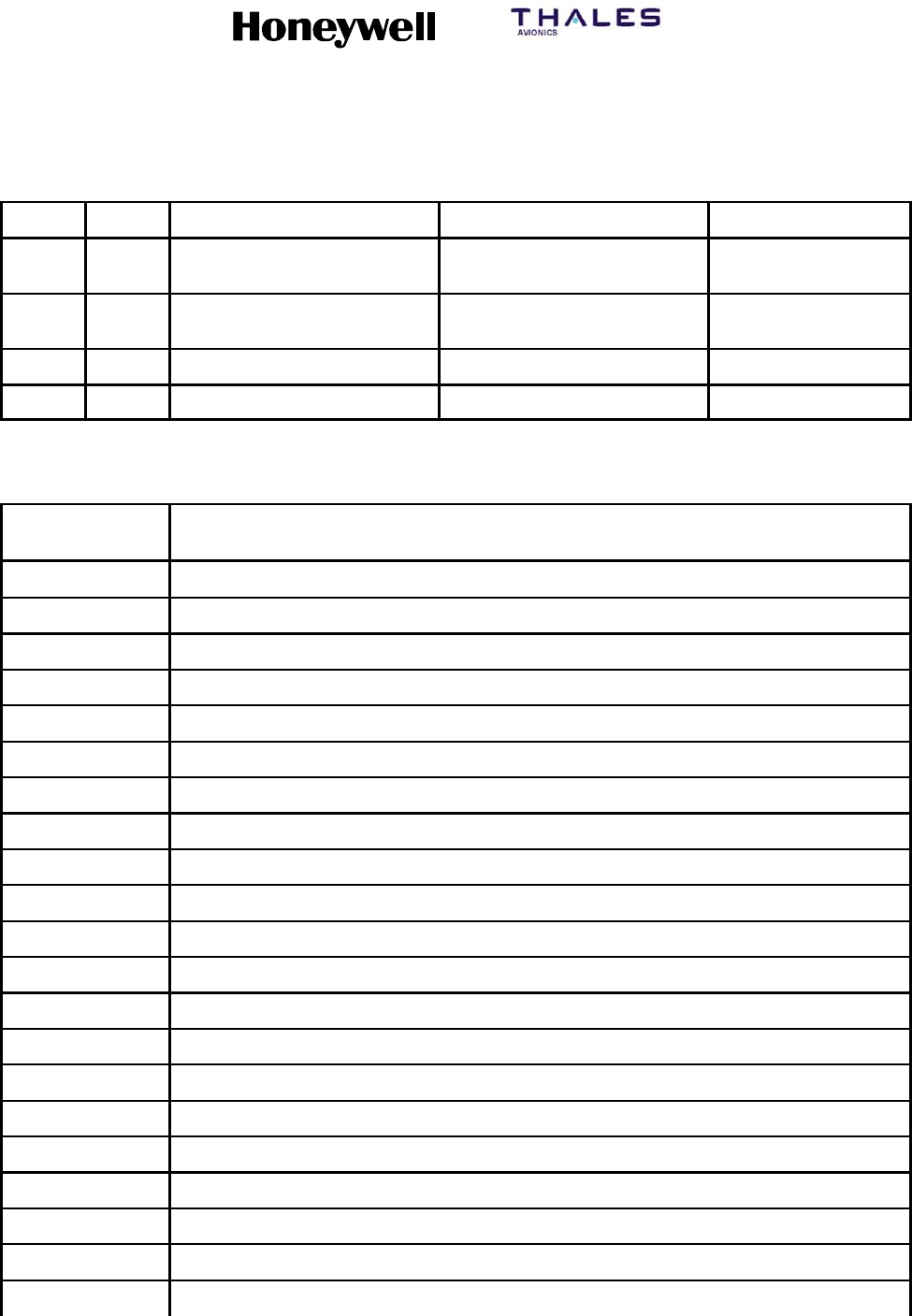
SYSTEM DESCRIPTION, INSTALLATION, AND MAINTENANCE MANUAL
MCS--4200/7200 Multi--Channel SATCOM System
23--20--35 15 Jul 2006
Honeywell International Inc. Do not copy without express permission of Honeywell.
Page E--18
Table E--4. SLCV Cause Codes and Strings (cont)
SLCV CommentsDetailed cause stringSLCV cause stringdddd
0000 034E MPDS channel cleared Bearer Control -- Status
Acknowledgement failure
0000 034F MPDS channel cleared Bearer Control -- Incorrect
SAN ID
0000 035C MPDS channel cleared No such MAN
0000 035D MPDS channel cleared Invalid L3 Call Reference
Table E--5. Q.850 Cause Codes and Strings
Q.850 Value
(qqq) Q8.50 string
1Unallocated number
2No route to specified transit network
3No route to destination
4Send special information tone
5Misdialed trunk prefix
6Channel unacceptable
7Call awarded and being delivered in an established channel
8Preemption
9Preemption -- circuit reserved for reuse
10 Normal call clearing
16 Normal call clearing
17 User busy
18 No user responding
19 No answer from user
20 Subscriber absent
21 Call rejected
22 Number changed
26 Non--selected user clearing
27 Destination out of order
28 Invalid number format -- address incomplete
29 Facility rejected

SYSTEM DESCRIPTION, INSTALLATION, AND MAINTENANCE MANUAL
MCS--4200/7200 Multi--Channel SATCOM System
23--20--35 15 Jul 2006
Honeywell International Inc. Do not copy without express permission of Honeywell.
Page E--19
Table E--5. Q.850 Cause Codes and Strings (cont)
Q.850 Value
(qqq) Q8.50 string
30 Response to a status enquiry
31 Normal, unspecified
34 No circuit/channel available
38 Network out of order
39 Permanent frame mode connection out--of--service
40 Permanent frame mode connection operational
41 Temporary failure
42 Switching equipment congestion
43 Access information discarded
44 Request channel not available
46 Precedence call blocked
47 Resource not available
49 Quality of service unavailable
50 Requested facility not subscribed
52 Outgoing calls barred
53 Outgoing calls barred within CUG
54 Incoming calls barred
55 Incoming calls barred within CUG
57 Bearer capability not authorized
58 Bearer capability not presently available
62 Inconsistency in designated outgoing access information and subscriber class
63 Service or option not available
65 Bearer capability not implemented
66 Channel type not implemented
69 Request facility not implemented
70 Only restricted digital information bearer capability is available
79 Service or option not implemented, unspecified
81 Invalid call reference value
82 Identified channel does not exist
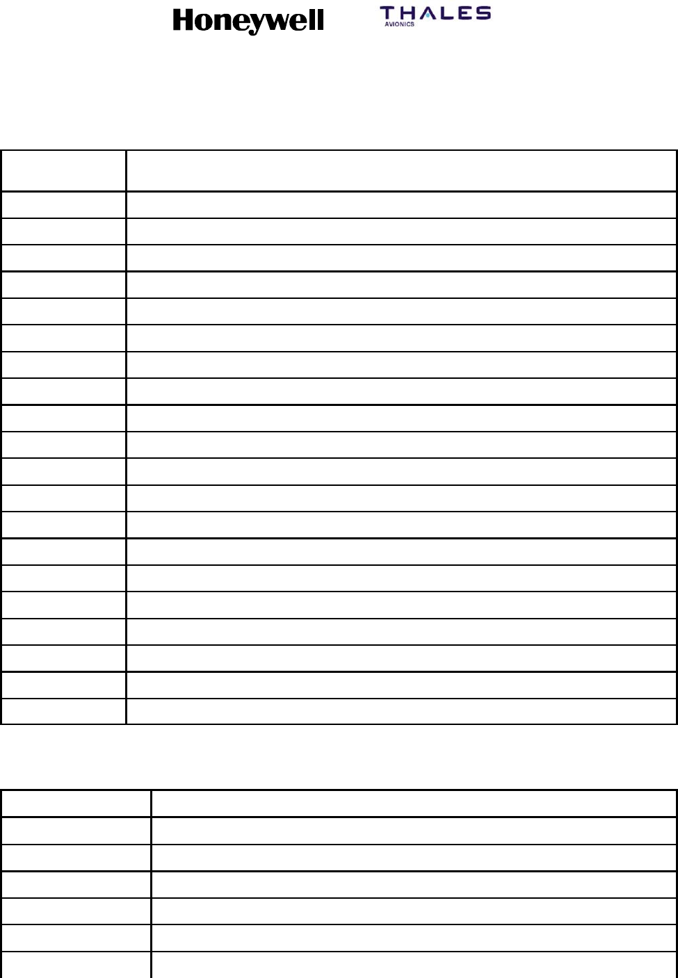
SYSTEM DESCRIPTION, INSTALLATION, AND MAINTENANCE MANUAL
MCS--4200/7200 Multi--Channel SATCOM System
23--20--35 15 Jul 2006
Honeywell International Inc. Do not copy without express permission of Honeywell.
Page E--20
Table E--5. Q.850 Cause Codes and Strings (cont)
Q.850 Value
(qqq) Q8.50 string
83 Suspended call exists, but call identity does not
84 Call identity in use
85 No call suspended
86 Call with the specified call identity is cleared
87 User not a member of CUG
88 Incompatible destination
90 Non--existent CUG
91 Invalid transit network selection
95 Invalid message, unspecified
96 Mandatory information element is missing
97 Message type non--existent or not implemented
98 Message not compatible with call state or message type non--existent
99 Information element non--existent or not implemented
100 Invalid information element contents
101 Message not compatible with call state
102 Recovery on timer expiry
103 Parameter non--existent or not implemented -- passed on
110 Message with unrecognized parameter, discarded
111 Protocol error, unspecified
127 Internetworking, unspecified
Table E--6. MPDS +WQ Cause Codes and Strings
mmm +WQ cause code string
100 MPDS Port error code 100 401
500 Unknown Error 500
501 LES Access Code does not support MPDS
502 Network does not recognize Mobile ID
503 Network does not recognize Sim Card
504 Authentication Failed to Complete

SYSTEM DESCRIPTION, INSTALLATION, AND MAINTENANCE MANUAL
MCS--4200/7200 Multi--Channel SATCOM System
23--20--35 15 Jul 2006
Honeywell International Inc. Do not copy without express permission of Honeywell.
Page E--21
Table E--6. MPDS +WQ Cause Codes and Strings (cont)
mmm +WQ cause code string
505 Authentication Failure
506 Authorization Failure
507 Authorization Failure -- Mobile Barred
508 Authorization Failure -- Mobile Barred on this LES Access Code
509 Authorization Failure -- SIM Card Barred on this LES Access Code
510 Authorization Failure -- Temporarily Unable to Accept Credit Cards
511 Authorization Failure -- Unable to Accept Credit Cards
512 Authorization Failure -- Credit Card Refused
513 Authorization Failure -- This Service not Allowed
514 Authorization Failure -- Service Option(s) not Allowed
515 Authorization Failure -- QoS not Allowed
516 Authorization Failure -- Unsupported Service Option(s)
517 QoS Option(s) Unsupported By Mobile
518 QoS Option(s) Unsupported By Network
519 Satellite Network Congestion
520 Satellite Network Unavailable
521 Service Congestion
522 Service Unavailable
523 Terrestrial Network Congestion
524 Terrestrial Network Unavailable
525 Terrestrial Network Destination -- Busy
526 Terrestrial Network Destination -- No Answer
527 Terrestrial Network Destination -- Unavailable
528 Terrestrial Network Destination -- No Carrier
529 Service Timed Out
530 Terminated by Network Operator
531 Insufficient Resources at Mobile
532 Mobile Failure
533 Mobile -- Connection to DTE Lost
534 Mobile -- Unrecoverable DTE Protocol Error

SYSTEM DESCRIPTION, INSTALLATION, AND MAINTENANCE MANUAL
MCS--4200/7200 Multi--Channel SATCOM System
23--20--35 15 Jul 2006
Honeywell International Inc. Do not copy without express permission of Honeywell.
Page E--22
Table E--6. MPDS +WQ Cause Codes and Strings (cont)
mmm +WQ cause code string
535 Mobile Reset
536 User Cancellation of Connection Establishment
600 Unable to Find Satellite Access Node
601 Unable to Establish Communication with Satellite Access Node
602 Link with Satellite Access Node Lost
700 Reason Unspecified
701 L3 Release
702 L3 Deregister
703 L3 Reject
716 SAN Idle Timer Expiry
717 MAN Idle Timer Expiry
718 SAN Connect Timer
719 SAN Modify Timer
720 SAN Handover Timer
721 SAN Connection Timer
722 MAN Connection Timer
732 Insufficient operating system resources at MAN
733 Insufficient memory at MAN
748 Invalid L3 Call Ref in Establish SDU
749 Invalid L3 Call Ref in Modify SDU
764 Unsupported MPDS MAC version
765 Invalid Bearer Connection type in Establish SDU
766 Invalid Bearer Control type in Establish SDU
767 Invalid Bearer Connection ID in Establish SDU
768 Invalid Bearer Connection type in Modify SDU
769 Invalid Bearer Control type in Modify SDU
770 Invalid Bearer Connection ID in Modify SDU
771 Invalid Handover SDU
772 Invalid SDU type
773 SDU Incorrectly Formatted
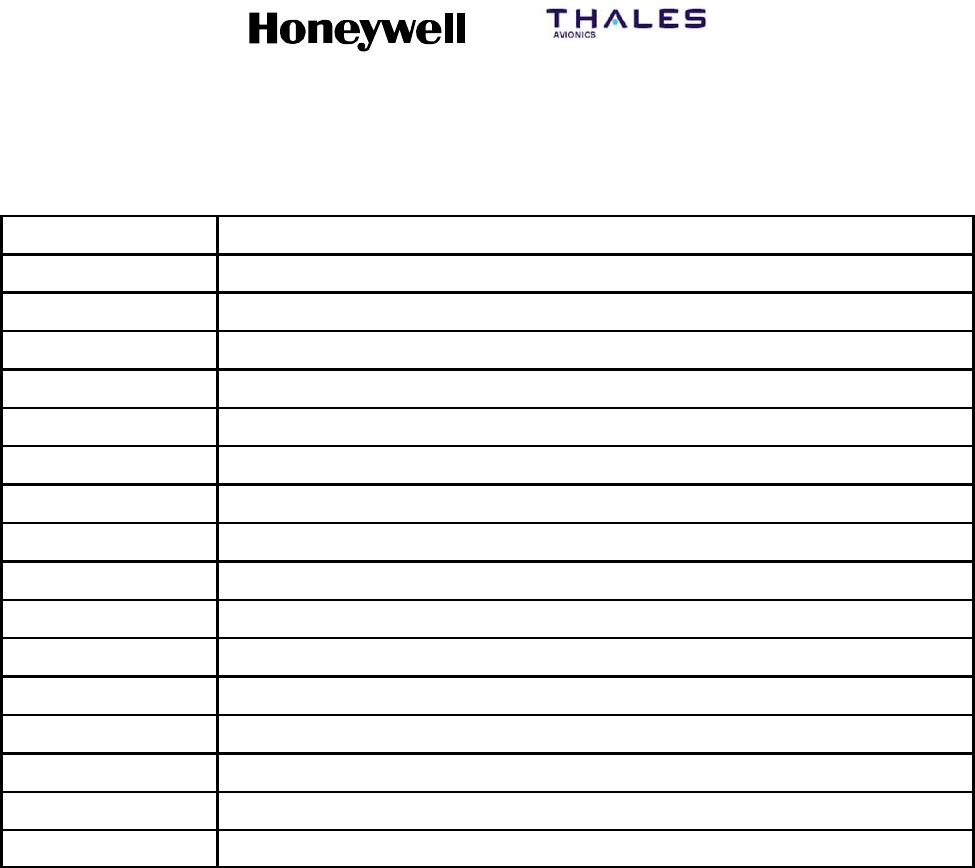
SYSTEM DESCRIPTION, INSTALLATION, AND MAINTENANCE MANUAL
MCS--4200/7200 Multi--Channel SATCOM System
23--20--35 15 Jul 2006
Honeywell International Inc. Do not copy without express permission of Honeywell.
Page E--23
Table E--6. MPDS +WQ Cause Codes and Strings (cont)
mmm +WQ cause code string
780 Connection sub--layer protocol failure (MAN specific signaling)
781 Connection sub--layer protocol failure (HDLC signaling)
796 Control sub--layer protocol failure
812 Channel Unit failure
813 Hardware failure
814 MAN not responding to frequency corrections
815 MAN not responding to power corrections
816 MAN not responding to timing corrections
828 Internal SAN failure
829 SAN Shutting Down
844 Bearer Control -- No satellite link
845 Bearer Control -- No suitable contention slot
846 Bearer Control -- Status Acknowledgement failure
847 Bearer Control -- Incorrect SAN ID
860 No such MAN
861 Invalid L3 Call Reference

SYSTEM DESCRIPTION, INSTALLATION, AND MAINTENANCE MANUAL
MCS--4200/7200 Multi--Channel SATCOM System
23--20--35 15 Jul 2006
Honeywell International Inc. Do not copy without express permission of Honeywell.
Page E--24
Blank Page

SYSTEM DESCRIPTION, INSTALLATION, AND MAINTENANCE MANUAL
MCS--4200/7200 Multi--Channel SATCOM System
23--20--35 15 Jul 2006
Honeywell International Inc. Do not copy without express permission of Honeywell.
Page F--1
APPENDIX F
FAILURE OVERVIEW
1. Fault Codes
CODE FAILURE DESCRIPTION
UNKNOWN LEVEL 1 UNKNOWN SRU
00 0 01 RESERVED
00002 SPARE
00 0 03 RESERVED
00 0 04 RESERVED
00 0 05 RESERVED
00 0 06 RESERVED
00 0 07 RESERVED
00 0 08 RESERVED
SDU
UNKNOWN SDU SRU
01001 SPARE
01 0 02 HMPM HPA CMD WORD (143) UPDATE RATE FAIL
01 0 03 HMPM HPA CMD WORD (143) DATA FAIL
01 0 04 RESERVED
01 0 05 RESERVED
01 0 06 RESERVED
01 0 07 HSU1--SDU W’BURG DATA TX FAIL
01 0 08 HSU1--SDU W’BURG SOLO WORD ACK FAIL
01009 SPARE
0100A SPARE
01 0 0B HSU2--SDU W’BURG DATA TX FAIL
01 0 0C HSU2--SDU W’BURG SOLO WORD ACK FAIL
0100D SPARE
0100E SPARE
0100F SPARE
01 0 10 HGA HPA COMMAND WORD (NCD)
01011 SPARE
01 0 12 LGA HPA COMMAND WORD (NCD)
01 0 13 RESERVED
01 0 14 RESERVED
01 0 15 RESERVED
01 0 96 INCOMPLETE ID PROM RESPONSES

SYSTEM DESCRIPTION, INSTALLATION, AND MAINTENANCE MANUAL
MCS--4200/7200 Multi--Channel SATCOM System
23--20--35 15 Jul 2006
Honeywell International Inc. Do not copy without express permission of Honeywell.
Page F--2
CODE FAILURE DESCRIPTION
SMPM: SDU MAIN PROCESSOR MODULE
01 1 81 SDU H/W--S/W COMPATIBILITY FAIL
01 1 82 BATTERY VOLTAGE LOW
01 1 83 WATCHDOG TIMEOUT FAIL
01 1 84 MICRO BOOT ROM FAIL
01 1 85/05 EEPROM FAIL
01 1 86/06 FLASH FAIL
01 1 87/07 SRAM FAIL
01 1 88/08 REAL TIME CLOCK FAIL
01189 QUARTFAIL
01 1 0A SOFTWARE ERROR (SYSFAIL)
01 1 0B FLASH--PSRAM MISCOMPARE
01 1 0C FLASH--PSRAM MISCOMPARE EXTENSION
01 1 0D FLASH--PSRAM MISCOMPARE EXTENSION
CODA: SDU VOICE CODEC MODULE A
01 2 81/01 <CODEC--A> PROGRAM MEMORY CRC FAIL
01 2 82 <CODEC--A> RESERVED
01 2 83 <CODEC--A> RESERVED
01 2 84 <CODEC--A> RESERVED
01 2 05 <CODEC--A> RESERVED
01 2 86 <CODEC--A> RESERVED
01 2 87/07 <CODEC--A> TIMING GENERATOR FAIL
01 2 88 <CODEC--A> DUAL PORT RAM FAIL CODEC SIDE
01 2 89 <CODEC--A> RESERVED
01 2 8A/0A <CODEC--A> PROGRAM MEMORY W/R FAIL
01 2 8B PP <CODEC--A> DSP INTERNAL MEMORY W/R FAIL
01 2 8C/0C <CODEC--A> DSP COMPREHENSIVE FAIL
01 2 0D <CODEC--A> HEALTH COUNT UPDATE
01 2 8E <CODEC--A> DUAL PORT RAM FAIL SMPM SIDE
01 2 0F <CODEC--A> SPARE
01 2 90 <CODEC--A> BUS ERROR
01 2 91 <CODEC--A> SELF TEST MISOPERATION
01 2 12 <CODEC--A> COMMUNICATION PROBLEM
01 2 93/13 <CODEC--A> RESERVED
01 2 94 <CODEC--A> ST BUS AUDIO LOOPBACK FAIL
01 2 95 <CODEC--A> SW DOWNLOAD FAIL

SYSTEM DESCRIPTION, INSTALLATION, AND MAINTENANCE MANUAL
MCS--4200/7200 Multi--Channel SATCOM System
23--20--35 15 Jul 2006
Honeywell International Inc. Do not copy without express permission of Honeywell.
Page F--3
CODE FAILURE DESCRIPTION
CODB: SDU VOICE CODEC MODULE B
01 3 Same entries as for CODA above except substitute CODB for CODA, SRU code 3 for
code 2, [CODEC_B] for [CODEC_A] and <CODEC--B> for <CODEC--A>.
Fault codes for codecs C--F have Level 2 (SRU) codes E--H. They are listed in the appropriate
section of this table for those SRU codes.
SIOM: SDU INPUT/OUTPUT MODULE (EXCLUSIVE TO SIOM)
01 4 81 A429 XMTR LOOP--BACK TO OTHER SDU FAIL
01 4 82 A429 XMTR LOOP--BACK TO CFDS FAIL
01 4 83 A429 XMTR LOOP--BACK TO ADL FAIL
01 4 84 A429 XMTR LOOP--BACK TO PDL FAIL
01 4 85 A429 XMTR LOOP--BACK TO (C)MUs FAIL
01 4 86 A429 XMTR LOOP--BACK TO SCDUs FAIL
01 4 87 A429 XMTR LOOP--BACK TO MULTI--CNTRL FAIL
01 4 88 RESERVED
01 4 89 A429 XMTR LOOP--BACK TO RMP/CAP FAIL
01 4 8A A429 XMTR LOOP--BACK TO SNU/CPDF FAIL
01 4 8B A429 XMTR LOOP--BACK TO HSU1 FAIL
01 4 8C A429 XMTR LOOP--BACK TO HSU2 FAIL
01 4 8D A429 XMTR LOOP--BACK SPARE
01 4 8E A429 XMTR LOOP--BACK SPARE
01 4 8F A429 XMTR LOOP--BACK SPARE
01 4 90 A429 XMTR LOOP--BACK SPARE
01 4 91 RESERVED
014AB SIOMBUSERROR
01 4 2C A429 TX TO OTHER SDU BUFFER FULL
01 4 2D A429 TX TO CFDS BUFFER FULL
0142E A429TXTOADLBUFFERFULL
0142F A429TXTOPDLBUFFERFULL
01 4 30 A429 TX TO (C)MUs BUFFER FULL
01 4 31 A429 TX TO SCDUs BUFFER FULL
01 4 32 A429 TX TO MULTI--CTRL BUFFER FULL
01 4 33 RESERVED
01 4 34 A429 TX TO RMP/CAP BUFFER FULL
01 4 35 A429 TX TO SNU/CPDF BUFFER FULL
01 4 36 A429 TX TO HSU1 BUFFER FULL
01 4 37 A429 TX TO HSU2 BUFFER FULL
01 4 38 A429 TX BUFFER FULL SPARE
01 4 39 A429 TX BUFFER FULL SPARE

SYSTEM DESCRIPTION, INSTALLATION, AND MAINTENANCE MANUAL
MCS--4200/7200 Multi--Channel SATCOM System
23--20--35 15 Jul 2006
Honeywell International Inc. Do not copy without express permission of Honeywell.
Page F--4
CODE FAILURE DESCRIPTION
01 4 3A A429 TX BUFFER FULL SPARE
01 4 3B A429 TX BUFFER FULL SPARE
01 4 BC SIOM INTERRUPT FAIL
01 4 3D IRS ASIC MATCHING PROBLEM
SMDM1: SDU MODEM MODULE #1
01 5 81 <MODEM--1> PROCESSOR FAIL
01 5 82/02 RESERVED
01 5 83/03 RESERVED
01 5 84/04 <MODEM--1> PROGRAM CRC FAIL
01 5 85/05 RESERVED
01 5 86/06 RESERVED
01 5 87 RESERVED
01 5 88/08 RESERVED
01 5 89/09 RESERVED
01 5 0A <MODEM--1>MODEM TO RFM INTERFACE FAIL
01 5 8B <MODEM--1> TIMER/INTERRUPT FAIL
01 5 8C RESERVED
01 5 8D RESERVED
01 5 8E <MODEM--1> EXTERNAL MEMORY FAIL
01 5 8F/0F RESERVED
01 5 90/10 RESERVED
01 5 91 <MODEM--1> MODEM DPR FAIL
01 5 92 RESERVED
01 5 93/13 RESERVED
01 5 94/14 RESERVED
01 5 95 <MODEM--1> SMPM SIDE DPR FAIL
01 5 16 <MODEM--1> SW DOWNLOAD FAIL
01 5 17 <MODEM--1> HEALTH COUNT UPDATE FAIL
01 5 18 RESERVED
01 5 99 <MODEM--1> BUS ERROR
01 5 9A <MODEM--1> SELF TEST MISOPERATION
01 5 1B <MODEM--1> SOFTWARE FAIL
01 5 1C <MODEM--1> COMMUNICATIONS PROBLEM
01 5 1D RESERVED
01 5 9E <MODEM--1> RFM SSI LOOPBACK FAIL
01 5 9F RESERVED

SYSTEM DESCRIPTION, INSTALLATION, AND MAINTENANCE MANUAL
MCS--4200/7200 Multi--Channel SATCOM System
23--20--35 15 Jul 2006
Honeywell International Inc. Do not copy without express permission of Honeywell.
Page F--5
CODE FAILURE DESCRIPTION
SMDM2: SDU MODEM MODULE #2
01 6 Same entries as for SMDM1 above except substitute SMDM2 for SMDM1, SRU code 6
for code 5, [MODEM_2] for [MODEM_1] and <MODEM-- 2> for <MODEM--1>.
SMDM3: SDU MODEM MODULE #3
01 7 Same entries as for SMDM1 above except substitute SMDM3 for SMDM1, SRU code 7
for code 5, [MODEM_3] for [MODEM_1] and <MODEM-- 3> for <MODEM--1>.
Fault codes for modems 4--7 have Level 2 (SRU) codes J, L, M and N. They are listed in this
table in the appropriate section for those SRU codes.
SRFM: SDU RADIO FREQUENCY MODULE
01 8 81 RESERVED
01 8 82 RESERVED
01 8 83 RESERVED
01 8 84 RESERVED
01 8 85 RESERVED
01 8 86 RESERVED
01 8 87 RESERVED
01 8 88 RESERVED
01 8 89 RESERVED
0180A SPARE
0180B SPARE
0180C SPARE
0180D SPARE
01 8 8E/0E RF SYNTH CHAN1 LOCK DETECT FAIL
01 8 8F/0F RESERVED
01 8 90/10 RF SYNTH CHAN2 LOCK DETECT FAIL
01 8 91/11 RESERVED
01 8 92/12 RF SYNTH CHAN3 LOCK DETECT FAIL
01 8 93/13 RESERVED
01 8 94/14 RESERVED
01 8 95/15 RESERVED
01 8 96/16 RF SYNTH CHAN4 LOCK DETECT FAIL
01 8 97/17 RF SYNTH CHAN5 LOCK DETECT FAIL
01 8 98/18 RF SYNTH CHAN6 LOCK DETECT FAIL
01 8 99/19 RF SYNTH CHAN7 LOCK DETECT FAIL
01 8 9A/1A RF SYNTH CHAN8 LOCK DETECT FAIL
01 8 9B/1B RF SYNTH TX BLOCK PLO LOCK DETECT FAIL
01 8 9C/1C RF SYNTH RX BLOCK PLO LOCK DETECT FAIL

SYSTEM DESCRIPTION, INSTALLATION, AND MAINTENANCE MANUAL
MCS--4200/7200 Multi--Channel SATCOM System
23--20--35 15 Jul 2006
Honeywell International Inc. Do not copy without express permission of Honeywell.
Page F--6
CODE FAILURE DESCRIPTION
01 8 9D/1D RF SYNTH RX CHAN PLO LOCK DETECT FAIL
01 8 9E/1E RF SYNTH TX DOPPLER PLO LOCK DETECT FAIL
01 8 A0 RFM CHAN 1 L--BAND LOOP--BACK (TX) FAIL
01 8 A1 RFM CHAN 1 L--BAND LOOP--BACK (RX) FAIL
01 8 A2 RFM CHAN 2 L--BAND LOOP--BACK (TX) FAIL
01 8 A3 RFM CHAN 2 L--BAND LOOP--BACK (RX) FAIL
01 8 A4 RFM CHAN 3 L--BAND LOOP--BACK (TX) FAIL
01 8 A5 RFM CHAN 3 L--BAND LOOP--BACK (RX) FAIL
01 8 A6 RFM CHAN 4 L--BAND LOOP--BACK (TX) FAIL
01 8 A7 RFM CHAN 4 L--BAND LOOP--BACK (RX) FAIL
01 8 A8 RFM CHAN 5 L--BAND LOOP--BACK (TX) FAIL
01 8 A9 RFM CHAN 5 L--BAND LOOP--BACK (RX) FAIL
01 8 AA RFM CHAN 6 L--BAND LOOP--BACK (TX) FAIL
01 8 AB RFM CHAN 6 L--BAND LOOP--BACK (RX) FAIL
01 8 AC RFM CHAN 7 L--BAND LOOP--BACK (TX) FAIL
01 8 AD RFM CHAN 7 L--BAND LOOP--BACK (RX) FAIL
01 8 AE RFM CHAN 8 L--BAND LOOP--BACK (TX) FAIL
01 8 AF RFM CHAN 8 L--BAND LOOP--BACK (RX) FAIL
01 8 30 RFM CHAN 1 TX CALIBRATION ERROR
01 8 31 RFM CHAN 2 TX CALIBRATION ERROR
01 8 32 RFM CHAN 3 TX CALIBRATION ERROR
01 8 33 RFM CHAN 4 TX CALIBRATION ERROR
01 8 34 RFM CHAN 5 TX CALIBRATION ERROR
01 8 35 RFM CHAN 6 TX CALIBRATION ERROR
01 8 36 RFM CHAN 7 TX CALIBRATION ERROR
01 8 37 RFM CHAN 8 TX CALIBRATION ERROR
01 8 38 RFM CHAN 1 RX CALIBRATION ERROR
01 8 39 RFM CHAN 2 RX CALIBRATION ERROR
01 8 3A RFM CHAN 3 RX CALIBRATION ERROR
01 8 3B RFM CHAN 4 RX CALIBRATION ERROR
01 8 3C RFM CHAN 5 RX CALIBRATION ERROR
01 8 3D RFM CHAN 6 RX CALIBRATION ERROR
01 8 3E RFM CHAN 7 RX CALIBRATION ERROR
01 8 3F RFM CHAN 8 RX CALIBRATION ERROR
01 8 C0/40 RFM CHAN 1 AGC TELLBACK FAIL
01 8 C1/41 RFM CHAN 2 AGC TELLBACK FAIL
01 8 C2/42 RFM CHAN 3 AGC TELLBACK FAIL
01 8 C3/43 RFM CHAN 4 AGC TELLBACK FAIL
01 8 C4/44 RFM CHAN 5 AGC TELLBACK FAIL

SYSTEM DESCRIPTION, INSTALLATION, AND MAINTENANCE MANUAL
MCS--4200/7200 Multi--Channel SATCOM System
23--20--35 15 Jul 2006
Honeywell International Inc. Do not copy without express permission of Honeywell.
Page F--7
CODE FAILURE DESCRIPTION
01 8 C5/45 RFM CHAN 6 AGC TELLBACK FAIL
01 8 C6/46 RFM CHAN 7 AGC TELLBACK FAIL
01 8 C7/47 RFM CHAN 8 AGC TELLBACK FAIL
01 8 C8/48 RFM BLOCK AGC TELLBACK FAIL
01 8 C9 I/Q CALIBRATION FAIL
01 8 D0 RFM CHAN 1 AGC CALIBRATION ERROR
01 8 D1 RFM CHAN 2 AGC CALIBRATION ERROR
01 8 D2 RFM CHAN 3 AGC CALIBRATION ERROR
01 8 D3 RFM CHAN 4 AGC CALIBRATION ERROR
01 8 D4 RFM CHAN 5 AGC CALIBRATION ERROR
01 8 D5 RFM CHAN 6 AGC CALIBRATION ERROR
01 8 D6 RFM CHAN 7 AGC CALIBRATION ERROR
01 8 D7 RFM CHAN 8 AGC CALIBRATION ERROR
01 8 D8 RFM BLOCK AGC CALIBRATION ERROR
SCFM: SDU CHANNEL FILTER MODULE
01 9 81/01 RESERVED
01 9 82/02 RESERVED
01 9 83/03 RESERVED
01 9 04 RESERVED
01 9 05 RESERVED
01 9 06 RESERVED
01 9 07 RESERVED
01 9 08 RESERVED
01 9 09 RESERVED
01 9 0A RESERVED
OCXO: SDU OVEN CONTROLLED CRYSTAL OSCILLATOR
01 A 01 OVEN READY FAIL
SMB: SDU MOTHER BOARD
01 B NONE
SPSU: SDU AC OR DC POWER SUPPLY UNIT
01 C 01 PSU TEMP LIMITS FAIL
01 C 02 SPARE
01 C 03 PSU SECONDARY VOLTAGE FAIL

SYSTEM DESCRIPTION, INSTALLATION, AND MAINTENANCE MANUAL
MCS--4200/7200 Multi--Channel SATCOM System
23--20--35 15 Jul 2006
Honeywell International Inc. Do not copy without express permission of Honeywell.
Page F--8
CODE FAILURE DESCRIPTION
SFPDM: SDU FRONT PANEL DISPLAY MODULE
01 D 01 TEST (PAST) SWITCH STUCK
01 D 02 MANUAL SCROLL SWITCH STUCK
CODC: SDU VOICE CODEC MODULE C
01 E Same entries as for CODA (01 2 xx) above except substitute CODC for CODA, SRU
code E for code 2, [CODEC_C] for [CODEC_A] and <CODEC--C> for <CODEC--A>.
CODD: SDU VOICE CODEC MODULE D
01 F Same entries as for CODA (01 2 xx) above except substitute CODD for CODA, SRU
code F for code 2, [CODEC_D] for [CODEC_A] and <CODEC--D> for <CODEC--A>.
CODE: SDU VOICE CODEC MODULE E
01 G Same entries as for CODA (01 2 xx) above except substitute CODE for CODA, SRU
code G for code 2, [CODEC_E] for [CODEC_A] and <CODEC--E> for <CODEC--A>.
CODF: SDU VOICE CODEC MODULE F
01 H Same entries as for CODA (01 2 xx) above except substitute CODF for CODA, SRU
code H for code 2, [CODEC_F] for [CODEC_A] and <CODEC--F> for <CODEC--A>.
01 I Not used.
SMDM4: SDU MODEM MODULE #4
01 J Same entries as for SMDM1 (01 5 xx) above except substitute SMDM4 for SMDM1,
SRU code J for code 5, [MODEM_4] for [MODEM_1] and <MODEM--4> for
<MODEM--1>.
01 K Not used.
SMDM5: SDU MODEM MODULE #5
01 L Same entries as for SMDM1 (01 5 xx) above except substitute SMDM5 for SMDM1,
SRU code L for code 5, [MODEM_5] for [MODEM_1] and <MODEM--5> for
<MODEM--1>.
SMDM6: SDU MODEM MODULE #6
01 M Same entries as for SMDM1 (01 5 xx) above except substitute SMDM6 for SMDM1,
SRU code M for code 5, [MODEM_6] for [MODEM_1] and <MODEM--6> for
<MODEM--1>.
SMDM7: SDU MODEM MODULE #7
01 N Same entries as for SMDM1 (01 5 xx) above except substitute SMDM7 for SMDM1,
SRU code N for code 5, [MODEM_7] for [MODEM_1] and <MODEM--7> for
<MODEM--1>.

SYSTEM DESCRIPTION, INSTALLATION, AND MAINTENANCE MANUAL
MCS--4200/7200 Multi--Channel SATCOM System
23--20--35 15 Jul 2006
Honeywell International Inc. Do not copy without express permission of Honeywell.
Page F--9
CODE FAILURE DESCRIPTION
VIM: VOICE INTERFACE MODULE
01 P 81 CABIN INTERFACE 1 AUDIO LOOPBACK FAIL
01 P 82 CABIN INTERFACE 2 AUDIO LOOPBACK FAIL
01 P 83 COCKPIT INTERFACE 1 AUDIO LOOPBACK FAIL
01 P 84 COCKPIT INTERFACE 2 AUDIO LOOPBACK FAIL
01 P 85 CTU CEPT--E1 AUDIO LOOPBACK FAIL
01 P 06 SPARE
01 P 07 CABIN AUDIO DISCRETE OUTPUTS LOOPBACK FAIL
01 P 08 COCKPIT AUDIO DISCRETE OUTPUTS LOOPBACK FAIL
01 P 89 CTU CEPT--E1 HDLC LOOPBACK FAIL
01 P 8A CABIN INTERFACE 1 BUS ERROR
01 P 8B CABIN INTERFACE 2 BUS ERROR
01 P 8C COCKPIT INTERFACE 1 BUS ERROR
01 P 8D COCKPIT INTERFACE 2 BUS ERROR
01 P 8E CTU CEPT--E1 BUS ERROR
“OTHER” SATCOM SYSTEM
02 0 01 PROTOCOL VERSION NUMBER INCOMPATIBLE
02 0 02 SDU/SDU MESSAGE PROTOCOL ERROR
HSU
Only applicable to Package 6.0 and subsequent.
UNKNOWN HSU SRU
03 0 01 HSU SELF--DECLARED FAILURE
03 0 02 HSU WILLIAMSBURG PROTOCOL ALO/ALR FAIL
03 0 03 HSU WILLIAMSBURG PROTOCOL DATA XFER FAIL
03 0 84 HSU SELF--TEST MISOPERATION
03 0 05 HSU SERIAL PORT MIS--WIRING
03 0 86/06 HSU TOTC RESET
03 0 87/07 HSU POC RESET
03008 SPARE
03 0 09--0B RESERVED
03 0 0C HSU CHANNEL 1 FAILURE
03 0 0D HSU CHANNEL RELEASE ACKNOWLEDGE FAILURE
03 0 8E/0E HSU RF LOOPBACK INHIBIT FAILURE
03 0 0F HSU CHANNEL 2 FAILURE
03 0 10 HSU CHANNEL 3 FAILURE
03 0 11 HSU CHANNEL 4 FAILURE

SYSTEM DESCRIPTION, INSTALLATION, AND MAINTENANCE MANUAL
MCS--4200/7200 Multi--Channel SATCOM System
23--20--35 15 Jul 2006
Honeywell International Inc. Do not copy without express permission of Honeywell.
Page F--10
CODE FAILURE DESCRIPTION
HSCC1: HSU CHANNEL CARD 1
03 1 01 HSU CC1 MODEM FAULT
03 1 02 HSU CC1 MODEM FAILURE
03 1 03 HSU CC1 PERIPHERAL ERROR
03 1 04 HSU CC1 PERIPHERAL FAILURE
03 1 05 HSU CC1 CP SW INCOMPATIBILITY
03 1 06 RESERVED
03 1 07 HSU CC1 RF FAULT
03 1 08 HSU CC1 RF FAILURE
03 1 09 HSU CC1 TAL ERROR
03 1 0A HSU CC1 MODEM CALIBRATION MISSING
03 1 0B HSU CC1 TEMPERATURE UNREADABLE
03 1 0C HSU CC1 OVER TEMPERATURE
03 1 0D RESERVED
03 1 0E HSU CC1 TURBO FAULT
03 1 0F HSU CC1 TURBO FAILURE
03 1 10 RESERVED
03 1 11 HSU CC1 VCODEC FAULT|
03 1 12 HSU CC1 VCODEC FAILURE
03 1 93 HSU CC1 APPLICATION CODE ERROR
HSCC2: HSU CHANNEL CARD 2
03 2 01 HSU CC2 MODEM FAULT
03 2 02 HSU CC2 MODEM FAILURE
03 2 03 HSU CC2 PERIPHERAL ERROR
03 2 04 HSU CC2 PERIPHERAL FAILURE
03 2 05 HSU CC2 CP SW INCOMPATIBILITY
03 2 06 RESERVED
03 2 07 HSU CC2 RF FAULT
03 2 08 HSU CC2 RF FAILURE
03 2 09 HSU CC2 TAL ERROR
03 2 0A HSU CC2 MODEM CALIBRATION MISSING
03 2 0B HSU CC2 TEMPERATURE UNREADABLE
03 2 0C HSU CC2 OVER TEMPERATURE
03 2 0D RESERVED
03 2 0E HSU CC2 TURBO FAULT
03 2 0F HSU CC2 TURBO FAILURE
03 2 10 RESERVED

SYSTEM DESCRIPTION, INSTALLATION, AND MAINTENANCE MANUAL
MCS--4200/7200 Multi--Channel SATCOM System
23--20--35 15 Jul 2006
Honeywell International Inc. Do not copy without express permission of Honeywell.
Page F--11
CODE FAILURE DESCRIPTION
03 2 11 HSU CC2 VCODEC FAULT
03 2 12 HSU CC2 VCODEC FAILURE
03 2 93 HSU CC2 APPLICATION CODE ERROR
HSDIO: HSU DATA I/O CARD
03 3 01 RESERVED
03 3 02 HSU UNRECOVERABLE SW / PROTOCOL ERROR
03 3 03 HSU I/O CHANNEL CARD 1 UNSERVICEABLE
03 3 04 HSU I/O CHANNEL CARD 2 UNSERVICEABLE
03 3 85 HSU CONFIGURATION ERROR
03 3 86 HSU I/O PERIPHERAL FAILURE
03 3 07 HSU I/O BOTH CHANNEL CARDS UNSERVICEABLE
03 3 08 HSU I/O RAM FAULT
03 3 09 HSU I/O ROM FAULT
03 3 0A HSU SW CONFIGURATION ERROR
03 3 0B HSU PPPoE SESSION FAILURE
HSCP: HSU CONTROL PROCESSOR
03 4 01 RESERVED
03 4 02 RESERVED
03 4 03 RESERVED
03 4 04 RESERVED
03 4 05 RESERVED
03 4 06 RESERVED
03 4 87/07 HSU CP CHANNEL CARD 1 UNRESPONSIVE
03 4 88/08 HSU CP CHANNEL CARD 2 UNRESPONSIVE
03 4 89/09 HSU CP BOTH CHANNEL CARDS UNRESPONSIVE
03 4 8A/0A HSU DATA I/O CARD UNRESPONSIVE
03 4 0B CM HSU CP RAM FAULT
03 4 0C CM HSU CP ROM FAULT
03 4 0D CM HSU OVER TEMPERATURE
03 4 0E CM HSU CHANNEL CARD 1 OVER TEMPERATURE
03 4 0F CM HSU CHANNEL CARD 2 OVER TEMPERATURE
03 4 10 CM HSU BOTH CHANNEL CARDS OVER TEMPERATURE
03 4 91 PP HSU ADL BUS INTERFACE FAILURE
03 4 92 PP HSU PDL BUS INTERFACE FAILURE
03 4 93 PP HSU DATA I/O DUART FAILURE
03 4 94 PP HSU CHANNEL CARD 1 DUART FAILURE

SYSTEM DESCRIPTION, INSTALLATION, AND MAINTENANCE MANUAL
MCS--4200/7200 Multi--Channel SATCOM System
23--20--35 15 Jul 2006
Honeywell International Inc. Do not copy without express permission of Honeywell.
Page F--12
CODE FAILURE DESCRIPTION
03 4 95 PP HSU CHANNEL CARD 2 DUART FAILURE
03 4 96 PP HSU BOTH CHANNEL CARDS DUART FAILURE
03 4 97 PP HSU MAINTENANCE INTERFACE DUART FAILURE
03 4 98 PP HSU DISCRETE OUTPUT FAILURE
03 4 99 PP HSU BOARD CONFIGURATION/REVISION FAILURE
HOCXO: HSU OVEN--CONTROLLED 10 MHZ OSCILLATOR
03 5 01 HSU OCXO TIMEOUT
03 5 02 HSU OCXO TEMPERATURE UNSTABLE
HSPSU: HSU POWER SUPPLY UNIT 1
03 6 01 HSU POWER SUPPLY FAIL
03 6 02 HSU PSU OVER TEMPERATURE
HSCDM: HSU CONFIGURATION DATA MODULE
037NONE
HSFP: HSU FRONT PANEL
03 8 81 HSU SELF--TEST BUTTON STUCK
HSBP: HSU BACKPLANE
039NONE
HGA/IGA HPA
This section lists failure codes inclusive of all HPA designs. Each HPA uses the SRU codes
appropriate to its design.
UNKNOWN HGA/IGA HPA SRU
04 0 01 <HGA HPA> STATUS WORD (143) UPDATE RATE FAIL
04 0 02 <HGA HPA> STATUS WORD (143) DATA FAIL
04 0 03 <HGA HPA> MNTNC WORD (350) UPDATE RATE FAIL
04 0 04 <HGA HPA> MNTNC WORD (350) DATA FAIL
04 0 05 <HGA HPA> SPARE
04 0 06 <HGA HPA> SPARE
04 0 87 <HGA HPA> SELF--TEST MISOPERATION
04 0 08 <HGA HPA> RF OVERDRIVE ERROR
04 0 09 <HGA HPA> RF SUPPLY CURRENT FAIL
04 0 0A <HGA HPA> OVER TEMP (COMB/DET) SHUTDOWN
04 0 0B <HGA HPA> NO RESPONSE TO CARRIER COMMAND
04 0 0C <HGA HPA> FAILURE WARNING W/NO DISC’S SET

SYSTEM DESCRIPTION, INSTALLATION, AND MAINTENANCE MANUAL
MCS--4200/7200 Multi--Channel SATCOM System
23--20--35 15 Jul 2006
Honeywell International Inc. Do not copy without express permission of Honeywell.
Page F--13
CODE FAILURE DESCRIPTION
04 0 0D <HGA HPA> 429 MNTNC WORD PSU FAIL (350)
04 0 0E <HGA HPA> 429 MNTNC WORD INTERNAL RAM FAIL
04 0 0F <HGA HPA> 429 MNTNC WORD INTERNAL ROM FAIL
04 0 10 <HGA HPA> CLASS C HPA MAX AVAIL PWR FAIL
04 0 40 <HGA HPA> SELF--TEST BUTTON STUCK
04 0 41 <HGA HPA> RESERVED (HP--720 “RF Power Input Low”)
HPSU: HPA AC OR DC POWER SUPPLY UNIT
04 1 01 <HGA HPA> PSU OVER TEMP SHUTDOWN
04 1 02 <HGA HPA> PSU TEMP SENSOR FAIL
04 1 03 <HGA HPA> PSU BIAS +5VDC FAIL
04 1 04 <HGA HPA> PSU +28/+25.5 VDC FAIL
04 1 05 <HGA HPA> PSU +5 VDC FAIL
04106 <HGAHPA>PSU+15VDCFAIL
04 1 07 <HGA HPA> PSU --15 VDC FAIL
04 1 08 <HGA HPA> PSU --85 VDC FAIL
04 1 09 <HGA HPA> PSU +8 VDC FAIL
0410A <HGAHPA>PSU+16VDCFAIL
04 1 40 <HGA HPA> INTERNAL POWER SUPPLY FAIL
04 1 41 <HGA HPA> PSU OVER TEMP
HMPM: HPA MAIN PROCESSOR MODULE
04 2 81 <HGA HPA> H/W--S/W COMPATIBILITY FAIL
04 2 02 <HGA HPA> SPARE
04 2 83/03 <HGA HPA> BOOT FLASH MEMORY FAIL
04 2 04 <HGA HPA> A429 SDU XMTR LOOP--BACK FAIL
04 2 05 <HGA HPA> SPARE
04 2 06 <HGA HPA> SPARE
04 2 87 <HGA HPA> A429 MULTICNT RCVR FAIL
04 2 88 <HGA HPA> A429 ADL RCVR FAIL
04 2 89 <HGA HPA> A429 PDL--TO--HPA RCVR FAIL
04 2 0A <HGA HPA> MAINTENANCE MEMORY CRC FAIL
04 2 0B <HGA HPA> MAINTENANCE MEMORY WRITE FAIL
04 2 8C/0C <HGA HPA> CALIBRATION MEMORY CRC FAIL
04 2 0D <HGA HPA> CALIBRATION MEMORY WRITE FAIL
04 2 8E/0E <HGA HPA> PROGRAM FLASH MEMORY FAIL
04 2 0F <HGA HPA> SPARE
04290 <HGAHPA>RAMFAIL
04 2 11 <HGA HPA> CPU OVER TEMP SHUTDOWN

SYSTEM DESCRIPTION, INSTALLATION, AND MAINTENANCE MANUAL
MCS--4200/7200 Multi--Channel SATCOM System
23--20--35 15 Jul 2006
Honeywell International Inc. Do not copy without express permission of Honeywell.
Page F--14
CODE FAILURE DESCRIPTION
04 2 12 <HGA HPA> CPU TEMP SENSOR FAIL
04 2 93/13 <HGA HPA> CPU GND REF FAIL
04 2 94/14 <HGA HPA> FAN RELAY DRIVER FAIL
04 2 95/15 <HGA HPA> BIAS ENABLE LOOPBACK FAIL
04 2 96/16 <HGA HPA> VAR ATTN DRIVER FAIL
04 2 17 <HGA HPA> FRONT PANEL TEST SWITCH STUCK
04 2 98 <HGA HPA> WATCHDOG TIMEOUT FAIL
04 2 19 <HGA HPA> DRIVER GND FAIL
04 2 1A <HGA HPA> SPARE
04 2 1B <HGA HPA> SPARE
04 2 9C/1C <HGA HPA> DRIVER TEST -- MUX
04 2 9D <HGA HPA> DRIVER TEST -- GREEN LED
04 2 9E <HGA HPA> DRIVER TEST -- RED LED
04 2 1F <HGA HPA> SPARE
04 2 A0 <HGA HPA> DRIVER TEST--MUTE ATTENUATOR
0 4 2 2 1 < H G A H P A > S PA R E -- -- -- -- --
04 2 A2 <HGA HPA> DRIVER TEST -- SER DATA CONCATENATE
04 2 23 <HGA HPA> SPARE
04 2 24 <HGA HPA> SPARE
04 2 A5 <HGA HPA> MUTE INPUT TEST
04 2 A6 <HGA HPA> CPU DEVICE TEST
04 2 A7 <HGA HPA> ACTUAL POWER CALIBRATION
04 2 A8 <HGA HPA> VALIDATION OF UPLOAD
04 2 29 <HGA HPA> MUTE ATTEN P OUT OF LIMITS
04 2 2A <HGA HPA> CODE VPP OUT OF LIMITS
04 2 2B <HGA HPA> MAINT LOG VPP OUT OF LIMITS
04 2 2C <HGA HPA> CAL MEM VPP OUT OF LIMITS
04 2 AD/2D <HGA HPA> ADC REF OUT OF LIMITS
04 2 2E <HGA HPA> PWR LO OUT OF LIMITS
04 2 2F <HGA HPA> PSU TEMP LO OUT OF LIMITS
04230 <HGAHPA>AMPSLOOUTOFLIMITS
04231 <HGAHPA>SOFTWAREFAULT
04 2 32 <HGA HPA> SPARE
04 2 B3/33 <HGA HPA> DISC OUTPUT TEST -- FAN
04 2 B4 <HGA HPA> RS--422 INTERNAL LOOPBACK FAIL
04 2 35 <HGA HPA> IGA LNA/DIP ON/OFF DISC LOOP FAIL
04 2 C0 <HGA HPA> I2C INTERFACE FAILURE
04 2 C1/41 <HGA HPA> RAM FAILURE
04 2 C2 <HGA HPA> KERNAL CODE ERROR

SYSTEM DESCRIPTION, INSTALLATION, AND MAINTENANCE MANUAL
MCS--4200/7200 Multi--Channel SATCOM System
23--20--35 15 Jul 2006
Honeywell International Inc. Do not copy without express permission of Honeywell.
Page F--15
CODE FAILURE DESCRIPTION
04 2 C3 <HGA HPA> APPLICATION CODE ERROR
04 2 C4 <HGA HPA> CONFIGURATION ERROR
04 2 C5 <HGA HPA> SDU BUS I/F FAILURE
04 2 C6 <HGA HPA> ADL BUS I/F FAILURE
04 2 C7 <HGA HPA> PDL BUS I/F FAILURE
04 2 C8 <HGA HPA> MAINTENANCE DUART FAILURE
04 2 C9/49 <HGA HPA> DISCRETE OUTPUTS FAILURE
04 2 CA/4A <HGA HPA> CP TEMP SENSOR FAILURE
04 2 CB <HGA HPA> BOARD CONFIG/REV FAILURE
0424C <HGAHPA>I
2C INTERFACE FAILURE
04 2 4D <HGA HPA> ROM FAILURE
DRIV: HPA RF DRIVER
04 3 01 <HGA HPA> DRIVER RF OUTPUT FAIL
04 3 02 <HGA HPA> DRIVER TEMP SENSOR FAIL
04 3 03 <HGA HPA> DRIVER OVER TEMP SHUTDOWN
04 3 04 <HGA HPA> DRIVER VCC FAIL
04 3 05 <HGA HPA> SPARE
SPLT: HPA RF SPLITTER
04 4 01 <HGA HPA> SPARE
PWR1: HPA RF POWER AMPLIFIER (1)
04 5 01 <HGA HPA> <AMP 1> RF BALANCE FAIL
04502 <HGAHPA><AMP1>VCCFAIL
04 5 03 <HGA HPA> SPARE
PWR2: HPA RF POWER AMPLIFIER (2)
04 6 Same as for PWR1 except sub. SRU code 6 for 5 and <AMP--2> for <AMP--1>.
PWR3: HPA RF POWER AMPLIFIER (3)
04 7 Same as for PWR1 except sub. SRU code 7 for 5 and <AMP--3> for <AMP--1>.
C/DET: HPA RF POWER COMBINER/DETECTOR
04 8 01 <HGA HPA> FORWARD OUTPUT POWER DET 1 FAIL
04 8 02 <HGA HPA> FORWARD OUTPUT POWER DET 2 FAIL
04 8 03 <HGA HPA> FORWARD OUTPUT PWR COMPARE FAIL
04 8 04 <HGA HPA> REFLECTED OUTPUT PWR DET FAIL
04 8 05 <HGA HPA> COMBINER TEMP SENSOR FAIL
04 8 06 <HGA HPA> SPARE

SYSTEM DESCRIPTION, INSTALLATION, AND MAINTENANCE MANUAL
MCS--4200/7200 Multi--Channel SATCOM System
23--20--35 15 Jul 2006
Honeywell International Inc. Do not copy without express permission of Honeywell.
Page F--16
CODE FAILURE DESCRIPTION
FPAMP: HPA RF FINAL POWER AMPLIFIER
04 9 01 <HGA HPA> FINAL AMP 1 RF BALANCE FAIL
04 9 02 <HGA HPA> FINAL AMP 1 VCC FAIL
04 9 03 <HGA HPA> SPARE
04 9 04 <HGA HPA> FINAL AMP 2 RF BALANCE FAIL
04 9 05 <HGA HPA> FINAL AMP 2 VCC FAIL
04 9 06 <HGA HPA> SPARE
04 9 C0/40 <HGA HPA> PA UNRESPONSIVE
04 9 41 <HGA HPA> SPARE
04 9 42 <HGA HPA> OVER CURRENT FAILURE
04 9 43 <HGA HPA> DRIVER AMPLIFIER DC VOLTAGE FAILURE
04 9 44 <HGA HPA> DRIVER AMPLIFIER CURRENT FAILURE
04 9 45 <HGA HPA> 12 VDC FAILURE
04 9 46 <HGA HPA> PA MUTE FAILURE
04947 <HGAHPA>PAOVERTEMP
04948 <HGAHPA>PASTATUSFAILURE
04 9 49 <HGA HPA> PA TEMP SENSOR FAILURE
HMB: HPA MOTHER BOARD
04 A 40 <HGA HPA> BP TEMP SENSOR FAILURE
RFAM: 20W HPA RF AMPLIFIER MODULE
04 B 01 <HGA HPA> OVER TEMP SHUTDOWN
04B02 <HGAHPA>RFAMVCCFAIL
04B03 <HGAHPA>AMP1VCCFAIL
04 B 04 <HGA HPA> FORWARD OUTPUT POWER DET 1 FAIL
04 B 05 <HGA HPA> FORWARD OUTPUT POWER DET 2 FAIL
04 B 06 <HGA HPA> REFLECTED OUTPUT PWR DET FAIL
04 B 07 <HGA HPA> TEMP SENSOR FAIL
04 B 08 <HGA HPA> FORWARD OUTPUT POWER FAIL
04 B 09 <HGA HPA> AMP 2 RF BALANCE FAIL
04B0A <HGAHPA>AMP2VCCFAIL
SPARE Level 1 Codes
05
06
LGA HPA
07 Same entries as for HGA/IGA HPA above except substitute LRU code 7 for code 4,
<LGA HPA> for <HGA HPA>, and [LGA_SUBSYS] for [HGA_SUBSYS]. For the cases
of conditional HGA subsystem indictments ([cond_HGA_SUBSYS]), the equivalent
LGA HPA failures shall UNconditionally indict [LGA_SUBSYS].

SYSTEM DESCRIPTION, INSTALLATION, AND MAINTENANCE MANUAL
MCS--4200/7200 Multi--Channel SATCOM System
23--20--35 15 Jul 2006
Honeywell International Inc. Do not copy without express permission of Honeywell.
Page F--17
CODE FAILURE DESCRIPTION
HSU #1
Only applicable prior to Package 6.0.
UNKNOWN <HSU1> SRU
08 0 01 <HSU1> SELF--DECLARED FAILURE
08 0 02 <HSU1> WILLIAMSBURG PROTOCOL ALO/ALR FAIL
08 0 03 <HSU1> WILLIAMSBURG PROTOCOL DATA XFER FAIL
08 0 84 <HSU1> SELF--TEST MISOPERATION
08 0 05 <HSU1> CHANNEL RELEASE ACKNOWLEDGE FAILURE
08 0 86/06 <HSU1> RF LOOPBACK INHIBIT FAILURE
HSCPU: <HSU1> CPU
08101--79 SPARE
08 1 FA <HSU1> ACCESS LEVEL DEVELOPMENT
08 1 FB <HSU1> ACCESS LEVEL PRODUCTION
08 1 FC <HSU1> ACCESS LEVEL PRODUCTION FAST STARTUP
08 1 FD <HSU1> SW VERSIONS INCONSISTENCY
0 8 1 7 E S PA R E -- -- -- -- --
08 1 7F <HSU1> ENVIRONMENT TEMP AT POWER--UP FAIL
0 8 1 8 0 -- 9 0 S PA R E -- -- -- -- --
08 1 91 <HSU1> TEMP SENSOR FAILURE
FDSMP: <HSU1> FRAME DSP (AND INTERFACES)
08201--14 SPARE
08 2 95 <HSU1> FRAME DSP/CPU INTERFACE FAILURE
VSDPM: <HSU1> VFC DSP (AND INTERFACES)
08301--17 SPARE
08 3 98 <HSU1> VFC DSP/CPU INTERFACE FAILURE
TFPGA: <HSU1> TURBO FPGA
08401--05 SPARE
08 4 86 <HSU1> TURBO FPGA FAIL
ISDNT: <HSU1> ISDN TRANSCEIVER
08501--06 SPARE
08 5 87 <HSU1> ISDN TRANSCEIVER FAILURE
AFPGA: <HSU1> ARINC 429 FPGA
086NONE

SYSTEM DESCRIPTION, INSTALLATION, AND MAINTENANCE MANUAL
MCS--4200/7200 Multi--Channel SATCOM System
23--20--35 15 Jul 2006
Honeywell International Inc. Do not copy without express permission of Honeywell.
Page F--18
CODE FAILURE DESCRIPTION
CPURM: <HSU1> CPU RAM
08701--03 SPARE
08 7 84 <HSU1> CPU RAM FAILURE
CEM: <HSU1> CONVERTER EEPROM
08 8 81 <HSU1> EEPROM FAILURE
FLASH: <HSU1> FLASH
08981 SPARE
08 9 82 <HSU1> PARAMETER BLOCK CHECKSUM FAILURE
08 9 83 <HSU1> CPU BIOS/APPLICATION CRC FAILURE
08904--06 SPARE
08 9 87 <HSU1> MISSING FILE IN FLASH
08 9 88 <HSU1> CORRUPTED FILE IN FLASH/INCORRECT CRC
QUART: <HSU1> QUAD UART
08 A 01--10 SPARE
08 A 91 <HSU1> EXTERNAL UART FAILURE
ETHER: <HSU1> ETHERNET
08 B NONE
PSPCB: <HSU1> POWER SUPPLY PCB
08 C 01--0A SPARE
08 C 0B <HSU1> POWER FAILURE
ETIME: <HSU1> EXTERNAL TIMER
08 D NONE
SPARE
08 E NONE
SPARE
08 F NONE
HCDMI: <HSU1>/CDM INTERFACE
08 G 01--71 SPARE
08 G F2 <HSU1> CDM INTERFACE FAILURE
08 G 73--7D SPARE
08 G FE <HSU1> CDM NOT FITTED

SYSTEM DESCRIPTION, INSTALLATION, AND MAINTENANCE MANUAL
MCS--4200/7200 Multi--Channel SATCOM System
23--20--35 15 Jul 2006
Honeywell International Inc. Do not copy without express permission of Honeywell.
Page F--19
CODE FAILURE DESCRIPTION
SPARE
08 H NONE
SPARE
08 I NONE
TDRAM: <HSU1> TURBO DECODER RAM
08 J 81--89 SPARE
08 J 8A <HSU1> TURBO DECODER RAM FAILURE
BATTM: <HSU1> BATTERY
08 K 01--04 SPARE
08 K 85 <HSU1> BATTERY CHECK FAILURE
IUART: <HSU1> INTERNAL UART
08LNONE
STAM: <HSU1> STEP ATTENUATOR
08 M 01--04 SPARE
08 M B5 <HSU1> STEP ATTENUATOR FAILURE
HRFM: <HSU1> RF
08 N 81 <HSU1> 1.LO LOCK DETECTOR FAILURE
08 N 82 <HSU1> 2.LO LOCK DETECTOR FAILURE
08 N 83 <HSU1> 3.LO LOCK DETECTOR FAILURE
08 N 04--10 SPARE
08 N 91 <HSU1> 1.LO MIN FREQUENCY TEST FAILURE
08 N 92 <HSU1> 2.LO MIN FREQUENCY TEST FAILURE
08 N 93 <HSU1> 3.LO MIN FREQUENCY TEST FAILURE
08 N 14--20 SPARE
08 N A1 <HSU1> 1.LO MAX FREQUENCY TEST FAILURE
08 N A2 <HSU1> 2.LO MAX FREQUENCY TEST FAILURE
08 N A3 <HSU1> 3.LO MAX FREQUENCY TEST FAILURE
08 N 24--2F SPARE
08 N B0 <HSU1> ALC -- CARRIER OFF FAILURE
08 N B1 <HSU1> ALC -- CARRIER ON FAILURE
08 N B2 <HSU1> RF LOOPBACK FAILURE
08 N B3 <HSU1> AVERAGE AMPLITUDE FAILURE
08 N B4 <HSU1> 16QAM SCPC FRAME SYNC FAILURE
08 N 35--39 SPARE

SYSTEM DESCRIPTION, INSTALLATION, AND MAINTENANCE MANUAL
MCS--4200/7200 Multi--Channel SATCOM System
23--20--35 15 Jul 2006
Honeywell International Inc. Do not copy without express permission of Honeywell.
Page F--20
CODE FAILURE DESCRIPTION
08 N BA <HSU1> INTERNAL RX COAX CABLE FAILURE
08 N BB <HSU1> TX/RX CHANNEL FREQUENCY ERROR
08 N BC <HSU1> CARRIER_ON OFF CONTROL FAILURE
08 N BD <HSU1> RF LOOP_BACK OFF CONTROL FAILURE
08 N BE <HSU1> TX_ON/OFF CONTROL FAILURE
08 N BF--40 SPARE
08 N 41 <HSU1> AGC LEVEL OUTSIDE LIMITS WARNING
08 N 42 SPARE
08 N C3 <HSU1> LINEARITY OUTSIDE LIMITS WARNING
08 N 44--50 SPARE
08 N 51 <HSU1> 1.LO LOCK FAILURE
08 N 52 <HSU1> 2.LO LOCK FAILURE
08 N 53 <HSU1> 3.LO LOCK FAILURE
REOSM: <HSU1> REFERENCE OSCILLATOR
08 O 01--41 SPARE
08 O 42 <HSU1> REF OSC WARNING: SEND HSU TO CAL
08 O 43--62 SPARE
08 O 63 <HSU1> REF OSC FAILURE/VOLTAGE TOO LOW
08 O 64 <HSU1> REF OSC FAILURE/VOLTAGE TOO HIGH
BMONM: <HSU1> BURST DURATION MONITOR
08 P 81 <HSU1> BURST DURATION MONITOR CIRCUIT
08 P 02--03 SPARE
08 P 04 <HSU1> TDM BURST DURATION FAILURE
08 P 85 <HSU1> CARRIER ON SIGNALS
DCOMM: <HSU1> DOPPLER COMPENSATION
08 Q 01--38 SPARE
08 Q 39 <HSU1> REF OSC COMPENSATION ERROR
FVFCI: <HSU1> FRAME DSP/VFC DSP INTERFACE
08 R 01--16 SPARE
08 R 17 <HSU1> FRAME DSP/VFC DSP FAILURE
FDTFI: <HSU1> FRAME DSP/TURBO FPGA INTERFACE
08 S 01--15 SPARE
08 S 96 <HSU1> FRAME TURBO FPGA INTERFACE FAILURE

SYSTEM DESCRIPTION, INSTALLATION, AND MAINTENANCE MANUAL
MCS-4200/7200
TEMPORARY REVISION NO. 23-1
23-20-35 Page 53 of 53
28 Sep 2009
© Honeywell International Inc. Do not copy without express permission of Honeywell.
INSERT PAGE 53 OF 53 FACING PAGE F-21.
Reason: To move 0B from the SPARE code at the bottom of the page and to add 0B to a new code
category HDM and applicable failure descriptions.
The SPARE code is changed and the new HDM code and subheading UNKNOWN HDM SRU are added
before the SPARE code as follows:
HDM
UNKNOWN HDM SRU
0B 0 81/01 HSU DATA MODULE ABSENT/REMOVED
0B 0 82 HDM USIM 1 ABSENT
0B 0 83/03 RESERVED
0B 0 84 HDM USIM 3 ABSENT
0B 0 85/05 RESERVED
0B 0 86 HDM USIMS 1 & 3 ABSENT
0B 0 07 HDM ORT FAILURE
0B 0 08 HDM TEMPERATURE UNSTABLE
0B 0 09 HDM TEMPERATURE TIMEOUT
0B 0 8A HDM USIM 1 INVALID
0B 0 8B/0B RESERVED
0B 0 8C HDM USIM 3 INVALID
0B 0 8D/0D RESERVED
0B 0 8E HDM USIM 1 & 3 INVALID
0B 0 8F/0F HDM USIM 1 FAILED
0B 0 90/10 RESERVED
0B 0 91/11 HDM USIM 3 FAILED
0B 0 92/12 RESERVED
0B 0 93/13 HDM USIM 1 & 3 FAILED
SPARE
0C

SYSTEM DESCRIPTION, INSTALLATION, AND MAINTENANCE MANUAL
MCS--4200/7200 Multi--Channel SATCOM System
23--20--35 15 Jul 2006
Honeywell International Inc. Do not copy without express permission of Honeywell.
Page F--21
CODE FAILURE DESCRIPTION
VDTFI: <HSU1> VFC DSP/TURBO FPGA INTERFACE
08 T NONE
VDITI: <HSU1> VFC DSP/ISDN TRANSCEIVER INTERFACE
08 U NONE
TFTDR: <HSU1> TURBO FPGA/TURBO DECODER RAM INTERFACE
08 V NONE
PSIPI: <HSU1> POWER SUPPLY PCB/ISDN PHONE INTERFACE
08 W 01--07 SPARE
08 W 88 <HSU1> ISDN SUPPLY VOLTAGE FAILURE
CDM: <HSU1> CONFIGURATION DATA MODULE
08 X 01--70 SPARE
08 X F1 <HSU1> INVALID SERIAL NUMBER
08 X 72 SPARE
08 X F3 <HSU1> CDM ESSENTIAL DATA FAILURE
08 X F4 <HSU1> CDM DATA ACCESS ERROR
08 X F5 <HSU1> CDM MISSING WRITE PROTECTION
08 X F6 <HSU1> CDM INCORRECT VERSION
SPARE
08 Y NONE
ITPSI: <HSU1> ISDN TRANSCEIVER/POWER SUPPLY PCB INTERFACE
08 Z 01--08 SPARE
08 Z 89 <HSU1> ISDN RX VOLTAGE
HSU #2
09 Same entries as for HSU #1 above except substitute LRU code 09 for code 08,
<HSU2> for <HSU1>, and [HSU2] for [HSU1]. Only applicable prior to Package 6.0.
HIGH POWER RELAY
UNKNOWN HPR SRU
0A 0 01 (PORT) MNTNC WORD HPR FAIL
0A 0 02 (STBD) MNTNC WORD HPR FAIL
SPARE
0B
0C

SYSTEM DESCRIPTION, INSTALLATION, AND MAINTENANCE MANUAL
MCS--4200/7200 Multi--Channel SATCOM System
23--20--35 15 Jul 2006
Honeywell International Inc. Do not copy without express permission of Honeywell.
Page F--22
CODE FAILURE DESCRIPTION
TOP/PORT LNA/DIPLEXER
UNKNOWN TOP/PORT LNA/DIPLEXER SRU
0D 0 01 <T/P LNA/DIP> MNTNC WORD FAIL
SPARE
0E
STARBOARD LNA/DIPLEXER
0F Same entries as for TOP/PORT LNA/Diplexer above except substitute STBD BSU for
T/P BSU, LRU code 0F for code 0D and <STBD LNA/DIP> for <T/P LNA/DIP>.
LGA LNA/DIPLEXER
UNKNOWN LGA LNA/DIPLEXER SRU
10 0 01 LGA LNA/DIP FAIL
SPARE
11
12
TOP/PORT BSU OR ACU
UNKNOWN TOP/PORT BSU OR ACU SRU
13 0 01 <T/P B/A> MNTNC WORD (350) UPDATE RATE FAIL
13 0 02 <T/P B/A> MNTNC WORD (350) DATA FAIL
13 0 03 <T/P B/A> STATUS WORD (144) UPDATE RATE FAIL
13 0 04 <T/P B/A> STATUS WORD (144) DATA FAIL
13 0 05 <T/P B/A> MNTNC WORD RAM FAIL
13 0 06 <T/P B/A> MNTNC WORD ROM FAIL
13 0 07 <T/P B/A> MNTNC WORD PSU FAIL
13 0 08 <T/P B/A> MNTNC WORD PARAMETER FAIL
13 0 09 <T/P B/A> MNTNC WORD TEMP FAIL
13 0 8A <T/P B/A> SELF--TEST MISOPERATION
SPARE
14
STARBOARD BSU
15 Same entries as for TOP/PORT BSU or ACU above except substitute LRU code 15 for
code 13 and <STBD BSU> for <T/P B/A>.

SYSTEM DESCRIPTION, INSTALLATION, AND MAINTENANCE MANUAL
MCS--4200/7200 Multi--Channel SATCOM System
23--20--35 15 Jul 2006
Honeywell International Inc. Do not copy without express permission of Honeywell.
Page F--23
CODE FAILURE DESCRIPTION
SPARE
16
17
18
19
TOP/PORT HGA/IGA
UNKNOWN TOP/PORT HGA/IGA SRU
1A 0 01 CM SMPM <T/P HGA/IGA> MNTNC WORD FAIL
1A 0 02 CM HMPM IGA FAILURE
1A 0 03 CM HMPM IGA RS--422 INPUT BUS LINK FAULT
1A 0 04 CM HMPM IGA HPA RS--422 INPUT BUS ERROR/INACTIVE
SPARE
1B
STARBOARD HGA
1C Same entries as for TOP/PORT HGA above except substitute LRU code 1C for code
1A, <STBD BSU> for <T/P B/A>, and <STBD HGA> for <T/P HGA>.
SPARE
1D
1E
LGA
UNKNOWN LGA SRU
1F RESERVED
SPARE
20
SCDU/WSC #1
UNKNOWN SCDU/WSC #1 SRU
21 0 01 <SCDU--1> PROTOCOL ERROR
21 0 02 <WSC--1> STATUS (270) BAD SSM
21 0 03 <WSC--1> MASTER PROTOCOL ERROR
21 0 04 <WSC--1> DATA TRANSMISSION FAILURE
21005 SPARE
21006 SPARE
21 0 07 <WSC--1> MASTER TEST LOOP FAILURE

SYSTEM DESCRIPTION, INSTALLATION, AND MAINTENANCE MANUAL
MCS--4200/7200 Multi--Channel SATCOM System
23--20--35 15 Jul 2006
Honeywell International Inc. Do not copy without express permission of Honeywell.
Page F--24
CODE FAILURE DESCRIPTION
21008 SPARE
SCDU/WSC #2
22 Same entries as for SCDU/WSC #1 above except substitute LRU code 22 for code 21,
<WSC--2> for <WSC--1>, and <SCDU--2> for <SCDU--1>.
SCDU/WSC #3
23 Same entries as for SCDU/WSC #1 above except substitute LRU code 23 for code 21,
<WSC--3> for <WSC--1>, and <SCDU--3> for <SCDU--1>.
SPARE
24--2F
RMP
UNKNOWN RMP SRU
30 RESERVED
SPARE
31
32
(C)MU #1
UNKNOWN (C)MU #1 SRU
33001 <(C)MU--1>SPARE----------
33 0 02 <(C)MU--1> STATUS (270) BAD SSM
33 0 03 <(C)MU--1> MASTER PROTOCOL ERROR
33 0 04 <(C)MU--1> DATA TRANSMISSION FAILURE
33 0 05 <(C)MU--1> SLAVE PROTOCOL ERROR
33 0 06 <(C)MU--1> SELF--DECLARED FAILURE
33 0 07 <(C)MU--1> MASTER TEST LOOP FAILURE
33 0 08 <(C)MU--1> SLAVE TEST LOOP FAILURE
(C)MU #2
34 Same entries as for CMU #1 above except substitute LRU code 34 for code 33 and
<(C)MU--2> for <(C)MU--1>.
IRS--PRI
UNKNOWN IRS--PRI SRU
35001 SPARE
35 0 02 <IRS--PRI> LAT DATA (310) FAIL
35003 SPARE

SYSTEM DESCRIPTION, INSTALLATION, AND MAINTENANCE MANUAL
MCS--4200/7200 Multi--Channel SATCOM System
23--20--35 15 Jul 2006
Honeywell International Inc. Do not copy without express permission of Honeywell.
Page F--25
CODE FAILURE DESCRIPTION
35 0 04 <IRS--PRI> LON DATA (311) FAIL
35005 SPARE
35 0 06 <IRS--PRI> GND SPD DATA (312) FAIL
35007 SPARE
35 0 08 <IRS--PRI> TRK DATA (313) FAIL
35009 SPARE
35 0 0A <IRS--PRI> TRUE HDG DATA (314) FAIL
3500B SPARE
35 0 0C <IRS--PRI> PITCH DATA (324) FAIL
3500D SPARE
35 0 0E <IRS--PRI> ROLL DATA (325) FAIL
IRS--SEC
36 Same entries as for IRS--PRI above except substitute LRU code 36 for code 35 and
<IRS--SEC> for <IRS--PRI>.
RESERVED
37
38
CFDS/CMC
UNKNOWN CFDS/CMC SRU
39 0 01 INVALID OMS PARAMETER(S) 3 3 E 29,34 NONE
SPARE
3A--3C
FMC #1
UNKNOWN FMC #1 SRU
3D RESERVED
FMC #2
3E Same entries as for FMC #1 above except substitute LRU code 3E for code 3D and
<FMC--2> for <FMC--1>.
SPARE
3F

SYSTEM DESCRIPTION, INSTALLATION, AND MAINTENANCE MANUAL
MCS--4200/7200 Multi--Channel SATCOM System
23--20--35 15 Jul 2006
Honeywell International Inc. Do not copy without express permission of Honeywell.
Page F--26
CODE FAILURE DESCRIPTION
429 ICAO ADDRESS SOURCE
UNKNOWN 429 ICAO ADDRESS SOURCE SRU
40 0 01 429 ICAO ADDRESS FAIL
40 0 02 DUAL SYSTEM DIFFERENT 429 AES ID
SPARE
41
CABIN TELECOMMUNICATIONS UNIT
UNKNOWN CABIN TELECOMMUNICATIONS UNIT SRU
42 0 01 CCS ECL NOT ESTABLISHED
42 0 02 CCS CCL NOT ESTABLISHED
42 0 03 CCS CTU NOT AVAILABLE
42 0 04 CCS PDL NOT ESTABLISHED
CPDF
43 Same entries as for CMU #1 above except substitute LRU code 43 for code 33,
<CPDF> for <(C)MU--1> and make the class of all CPDF failure 2.
SPARE
44 -- 4F
SDU INPUT BUSES AND RELATED
50 0 01 SDU HSU1 BUS INACTIVE
50 0 02 HSU1 SELF--TEST MISOPERATION
50 0 03 HSU1 PERIODIC DATA RATE FAIL
50004 HSU1SOLOWORDDATARATEFAIL
50 0 05 HSU1 W’BURG DATA RATE FAIL
51 0 01 SDU HSU2 BUS INACTIVE
51 0 02 HSU2 SELF--TEST MISOPERATION
51 0 03 HSU2 PERIODIC DATA RATE FAIL
51004 HSU2SOLOWORDDATARATEFAIL
51 0 05 HSU2 W’BURG DATA RATE FAIL
52 0 01 SDU CPDF BUS INACTIVE
53 0 01 SDU CMU--1 BUS INACTIVE
54 0 01 SDU CTU CEPT--E1 BUS INACTIVE
55 0 01 SDU SCDU/WSC--1 BUS INACTIVE
56 0 01 SDU SCDU/WSC--2 BUS INACTIVE
57 0 01 SDU CMU--2 BUS INACTIVE

SYSTEM DESCRIPTION, INSTALLATION, AND MAINTENANCE MANUAL
MCS--4200/7200 Multi--Channel SATCOM System
23--20--35 15 Jul 2006
Honeywell International Inc. Do not copy without express permission of Honeywell.
Page F--27
CODE FAILURE DESCRIPTION
58001 SPAREMP4A/B
59 0 01 SDU CFDS BUS INACTIVE
59 0 02 INVALID OMS PARAMETER(S)
5A 0 01 SDU PRI IRS BUS INACTIVE
5B 0 01 SDU SEC IRS BUS INACTIVE
5C 0 01 SDU HGA/IGA HPA BITE BUS INACTIVE
5C 0 02 HGA/IGA HPA SELF--TEST MISOPERATION
5D SPARE
5E SPARE MP6G/H
5F 0 01 SDU LGA HPA BITE BUS INACTIVE
5F 0 02 LGA HPA SELF--TEST MISOPERATION
60 SPARE MP7A/B
61 SPARE
62 0 01 SDU TOP/PORT BSU/ACU BITE BUS INACTIVE
62 0 02 TOP/PORT BSU/ACU SELF--TEST MISOPERATION
63 SPARE
64 0 01 SDU STBD BSU BITE BUS INACTIVE
64 0 02 STBD BSU/ACU SELF--TEST MISOPERATION
65 0 01 SDU RMP BUS INACTIVE
66 0 01 SDU SCDU/WSC--3 BUS INACTIVE
67 0 01 RESERVED
68 0 01 RESERVED
69 SPARE
6A 0 81 RESERVED
6B 0 01 SPARE
6C 0 81 RESERVED
6D 0 81 RESERVED
6E 0 81 RESERVED
6F 0 81 RESERVED
70 SPARE
71 0 01 SDU CROSS--TALK BUS INACTIVE 3 2 I -- [OTHER_SATCOM]
72 SPARE MP12E/F
73 0 01 SDU FMC--1 BUS INACTIVE
74 0 01 SDU FMC--2 BUS INACTIVE
75 SPARE
76 SPARE
77 SPARE
78 SPARE

SYSTEM DESCRIPTION, INSTALLATION, AND MAINTENANCE MANUAL
MCS--4200/7200 Multi--Channel SATCOM System
23--20--35 15 Jul 2006
Honeywell International Inc. Do not copy without express permission of Honeywell.
Page F--28
CODE FAILURE DESCRIPTION
79 SPARE
7A SPARE
7B SPARE
7C SPARE
7D SPARE
7E SPARE
7F SPARE
RESERVED
80--8F
HGA/IGA HPA INPUT BUSES
90 0 01 HGA/IGA HPA 429 MNTNC WORD CTL BUS INACTIVE
90 0 02 HGA/IGA HPA MULTICONTROL BUS INACTIVE
91 SPARE TP2A/B
92 SPARE
93 SPARE
94 SPARE
95 SPARE
LGA HPA INPUT BUSES
96 0 01 LGA HPA 429 MNTNC WORD CONTROL BUS INACTIVE
96 0 02 LGA HPA MULTICONTROL BUS INACTIVE
97 SPARE TP2A/B
TOP/PORT BSU/ACU INPUT BUSES
98 0 01 MNTNC WORD T/P BSU/ACU MULTICTL BUS INACTIVE
99 SPARE
PORT BSU INPUT BUSES
9A 0 01 MNTNC WORD PORT BSU CROSSTALK BUS INACTIVE
9B SPARE
STARBOARD BSU INPUT BUSES
9C 0 01 MNTNC WORD STBD BSU MULTICTL BUS INACTIVE
9D 0 01 MNTNC WORD STBD BSU CROSSTALK BUS INACTIVE

SYSTEM DESCRIPTION, INSTALLATION, AND MAINTENANCE MANUAL
MCS--4200/7200 Multi--Channel SATCOM System
23--20--35 15 Jul 2006
Honeywell International Inc. Do not copy without express permission of Honeywell.
Page F--29
CODE FAILURE DESCRIPTION
HSU #1 INPUT BUS
9E 0 01 <HSU1> 429 CONTROL BUS INACTIVE
9E 0 02 <HSU1> ICAO ADDRESS INVALID
9E 0 03 <HSU1> POSITION UNAVAILABLE
9E 0 04 <HSU1> VELOCITY UNAVAILABLE
HSU #2 INPUT BUS
9F Same as entries for HSU #1 above except substitute Level 1 code 9F for code 9E and
<HSU2> for <HSU1>. Only applicable prior to Package 6.0.
SPARE
A0 SPARE----------
WSC INPUT BUSES
A1 0 01 WSC1 429 CNTRL BUS FROM THIS SDU INACTIVE
A2 0 01 WSC2 429 CNTRL BUS FROM THIS SDU INACTIVE
A3 0 01 WSC3 429 CNTRL BUS FROM THIS SDU INACTIVE
SPARE
A4--A5
HSU USER INTERFACES
A6 0 01 HSU ETHERNET PORT 1 BUS INACTIVE
A7 0 01 HSU ETHERNET PORT 2 BUS INACTIVE
A8 0 01 HSU ISDN PORT 1 BUS INACTIVE
A9 0 01 HSU ISDN PORT 2 BUS INACTIVE
SPARE
AA--BF
MISCELLANEOUS ERRORS, FAILURES AND WARNINGS
SDU SYSTEM CONFIGURATION STRAP ERRORS
C0 0 81 SDU STRAPS PARITY ERROR
C0 0 82 SDU ANT CONFIG STRAPS ERROR
C0 0 83 SDU CFDS CONFIG STRAPS ERROR
C0 0 84 SDU STRAPS INCONSISTENCY
C0 0 05 DUAL SYSTEM CONFIG STRAPS ERROR
C0 0 06 DUAL REMOTE COCKPIT STRAPS INCOMPATIBLE
C0 0 87 MANUFACTURER--SPECIFIC STRAPS PARITY ERROR

SYSTEM DESCRIPTION, INSTALLATION, AND MAINTENANCE MANUAL
MCS--4200/7200 Multi--Channel SATCOM System
23--20--35 15 Jul 2006
Honeywell International Inc. Do not copy without express permission of Honeywell.
Page F--30
CODE FAILURE DESCRIPTION
MISC
C1 0 81/01 SDU WOW MISCOMPARE ERROR
C2 0 81 SDU DUAL SYSTEM SELECT/DISABLE TEST ERROR
C2 0 82 SDU DUAL SYSTEM SEL/DIS TEST NOT INITIATED
C3 0 81 SDU (ICAO) ADDRESS BITS (STRAPS) ERROR
C3 0 02 DUAL SYSTEM DIFFERENT STRAPS AES ID
C4 0 01 HGA/IGA HPA 429 MNTNC WORD OUTPUT VSWR BAD
C4 0 02 HGA/IGA HPA REFLECTED OUTPUT POWER ERROR
C5 0 81/01 ORT/LOCAL CONFIG STRAPS INCOMPATIBILITY
C5 0 02 DUAL ORT/COMBINED CONFIG STRAPS INCOMP
C6 0 01 LGA HPA 429 MNTNC WORD OUTPUT VSWR BAD
C6 0 02 LGA HPA REFLECTED OUTPUT POWER ERROR
HGA/IGA HPA OVER TEMP WARNINGS
C7 0 01 HGA HPA MNTNC WORD LRU OVER TEMP
C7 1 01 HGA HPA PSU OVER TEMP WARNING
C7 2 01 HGA HPA CPU OVER TEMP WARNING
C7 2 02 HGA HPA OVER TEMP WARNING
C7 3 01 HGA HPA DRIVER OVER TEMP WARNING
C7 8 01 HGA HPA OVER TEMP (COMBINER) WARNING
C7 B 01 HGA HPA RFAM OVER TEMP WARNING
MISC
C8 0 01 INVALID FREQ CMD FROM GES
C8 0 02 GNSS INTERFERENCE RISK FROM GES
LGA HPA OVER TEMP WARNINGS
C9 0 01 LGA HPA MNTNC WORD LRU OVER TEMP
C9 1 01 LGA HPA PSU OVER TEMP WARNING
C9 2 01 LGA HPA CPU OVER TEMP WARNING
C9 2 02 LGA HPA OVER TEMP WARNING
C9 3 01 LGA HPA DRIVER OVER TEMP WARNING
C9 8 01 LGA HPA OVER TEMP (COMBINER) WARNING
C9 B 01 LGA HPA RFAM OVER TEMP WARNING
MISC
CA 0 01 LGA LNA CONTROL DRIVER FAIL
CB 0 01 HGA/IGA HPA INVALID SDI STRAPPING
CC 0 01 LGA HPA INVALID SDI STRAPPING

SYSTEM DESCRIPTION, INSTALLATION, AND MAINTENANCE MANUAL
MCS--4200/7200 Multi--Channel SATCOM System
23--20--35 15 Jul 2006
Honeywell International Inc. Do not copy without express permission of Honeywell.
Page F--31
CODE FAILURE DESCRIPTION
TOTC/POC RESETS
CD 0 81/01 SDU TOTC AUTO/MANUAL RESET
CD 0 82/02 SDU POC AUTO/MANUAL RESET
CE 0 81/01 RESERVED
CE 0 82/02 RESERVED
CF 0 81/01 HGA/IGA HPA TOTC AUTO/MANUAL RESET
CF 0 82/02 HGA/IGA HPA POC AUTO/MANUAL RESET
D0 0 81/01 LGA HPA TOTC AUTO/MANUAL RESET
D0 0 82/02 LGA HPA POC AUTO/MANUAL RESET
WRONG SDI CODES
D1 0 01 HGA/IGA HPA WRONG A429 SDI CODE
D2 0 01 LGA HPA WRONG A429 SDI CODE
D3 0 01 TOP/PORT BSU/ACU WRONG A429 SDI CODE
D4 0 01 STARBOARD BSU WRONG A429 SDI CODE
RF INTER--LRU FAILURES
D5 0 01 SDU TO HGA/IGA HPA CALIBRATION ERROR
D5 0 02 SDU TO LINEAR HGA/IGA HPA RF CONTIN. FAIL
D5 0 03 SDU TO CLASS C HGA/IGA HPA RF CONTIN. FAIL
D5 0 04 SDU TO HGA/IGA HPA ATTEN. CALIBRATION ERROR
D5 0 05 SDU TO LINEAR HGA/IGA HPA ATTEN. RF CONTIN. FAIL
D6 0 01 SDU TO LGA HPA CALIBRATION ERROR
D6 0 02 SDU TO LINEAR LGA HPA RF CONTINUITY FAIL
D6 0 03 SDU TO CLASS C LGA HPA RF CONTINUITY FAIL
D6 0 04 SDU TO LGA HPA ATTEN. CALIBRATION ERROR
D6 0 05 SDU TO LINEAR LGA HPA ATTEN. RF CONTIN. FAIL
D7 0 01 RESERVED
D7 0 82 RESERVED
D8 0 81 T/P HGA LNA TO SDU RF CONTINUITY FAIL
D9 0 81 STBD HGA LNA TO SDU RF CONTINUITY FAIL
DA 0 81 LGA LNA TO SDU RF CONTINUITY FAIL
MISC
DB 0 01 LGA LOG--ON TEST FAILURE
DB 0 02 SLAVE LGA LOG--ON TEST NOT INITIATED
DC 0 01 NO DECLARED ACTIVE (C)MU -- 1

SYSTEM DESCRIPTION, INSTALLATION, AND MAINTENANCE MANUAL
MCS--4200/7200 Multi--Channel SATCOM System
23--20--35 15 Jul 2006
Honeywell International Inc. Do not copy without express permission of Honeywell.
Page F--32
CODE FAILURE DESCRIPTION
SDU ORT ERRORS
SDU SECURED ORT ERRORS
DD 0 01 (I) STARTUP LOG--ON POLICY
DD 0 02 RESERVED
DD 0 03 (VIII) RESPONSE CAPABILITY TO LOG--ON INTRRGTN
DD 0 04 (XVIII) NOISE INSERTION LEVEL
DD 0 05 (XXII) TX GAIN THRESHOLD
DD 0 06 (XXIII) APHONE SYSTEM MANAGEMENT COMMANDS
DD 0 07 RESERVED
DD 0 08 (XXVIII) HPA BACKOFF LIMITS
DD 0 09 (XXIX) HPA MIN REPORTABLE ACTUAL PWR OUT
DD 0 0A (XXX) DEFAULT ASSUMED GLOBAL INITIAL C--CH EIRP
DD 0 0B (XXXI) SCDU TELEPHONE NUMBER PRESELECT
DD 0 0C (XXXII) ACP CALL INITIATION
DD 0 0D (XXXVIII) FAILURE MASKING DATA
DD 0 0E (XXXIX) ELEVATION HANDOVER THRESHOLD
DD 0 0F (XLI) AUTOMATIC TRANSIT CALL GES TABLE
DD 0 10 (XLII) AIR--TO--GROUND CHIME
DD 0 11 (XLIII) SCDU CALL PROMPTS
DD 0 12 (XLIV) EIRP OVERDRAFT CHECKING PRIORITY
DD 0 13 (XLVI) COCKPIT AUDIO LEVEL SETTINGS
DD 0 14 (XLVII) HGA RETRY PERIOD
DD 0 15 (XLVIII) COCKPIT CHAN INTERFACE TYPE FOR DUAL
DD 0 16 (L) ”DIS/REENABLE OTHER SATCOM” SCDU PROMPTS
DD 0 17 (LI) SCDU SATCOM SUBSYSTEM PROMPTS
DD 0 18 (LII) SCDU CHANNEL LABEL SUFFIXES
DD 0 19 (LIII) SECURED ORT DESCRIPTION
DD 0 1A (LIV) COMPOSITE ORT FILE UPLOAD ALLOWED
DD 0 1B SECURED ORT MISMATCH WITH OTHER SDU
DD 0 1C (LVI) ACCESS TO ZERO--PREFERENCE GESS
DD 0 1D (LV) SECURED ORT MODIFIED FLAG
DD 0 1E (LVII) L--BAND REFERENCE OFFSET CAL THRESHOLDS
DD 0 1F (LIX) APHONE AUDIO LEVEL SETTING
DD 0 20 (LX) AERO--H ONLY OPERATION

SYSTEM DESCRIPTION, INSTALLATION, AND MAINTENANCE MANUAL
MCS--4200/7200 Multi--Channel SATCOM System
23--20--35 15 Jul 2006
Honeywell International Inc. Do not copy without express permission of Honeywell.
Page F--33
CODE FAILURE DESCRIPTION
SDU USER ORT ERRORS
DE 0 01 (II) SATELLITE/GES NAMES
DE 0 02 (III) GES PREFERENCE VALUES
DE 0 03 (IV) MAINTENANCE PAGE ACCESS
DE 0 04 (V) COCKPIT TELEPHONE NUMBERS
DE 0 05 (VII) RESOURCES RESERVED FOR HEADSET
DE 0 06 SPARE
DE 0 07 (X) GROUND--TO--AIR CIRCUIT--MODE DATA
DE 0 08 (XIII) GROUND--TO--AIR CALLS
DE 0 09 (XIV) CALL CAMP--ON DURATION
DE 0 0A (XV) CAMP--ON TIMEOUT ACTION
DE 0 0B (XVI) STORE APHONE TELEPHONE NUMBERS
DE 0 0C (XIX) GROUND--TO--AIR CALL PREEMPTION
DE 0 0D (XX) PREFERRED COCKPIT CALL ROUTING
DE 0 0E (XXI) PREFERRED APHONE CALL ROUTING
DE 0 0F (XXIV) APHONE OUTGOING CALL BARRING LEVEL
DE 0 10 (XXV) CALL BARRING SECURITY CODE
DE 0 11 (XXVI) SHARED APHONE PHONE NUMBER STORAGE
DE 0 12 (XXXIII) ORT DESCRIPTION
DE 0 13 (XXXIV) AIRLINE CODE
DE 0 14 (XXXV) HEADSET OUTGOING CALL BARRING LEVEL
DE 0 15 (XXXVI) HEADSET TRANSIT CALL
DE 0 16 (XL) HIGH RATE DATA TRANSMIT SUPPORT
DE 0 17 (XLV) APHONE CALLED TERMINAL ID ASSIGNMENT
DE 0 18 (IL) MASTERY HANDOVER ALGORITHM WEIGHTING
DE 0 19 (LVIII) AES POSITION REPORTING
DE 0 1A (LXI) HSD PREEMPTION FOR PRIORITY 4 CALLS
DE 0 1B (LXII) ONGOING HSD CALL EIRP
DE 0 1C (XXXVII) ORT MODIFIED FLAG
DE 0 1D (LXIII) WSC MANUAL DIALING
DE 0 1E (LXIV) MINIMUM HSD CALL EIRP
DE 0 1F (LXV) HSD REGISTRATION PREFERENCE
DE 0 20 (LXVI) SWIFT64 M--ISDN LES PREFERENCE VALUES
DE 0 21 (LXVII) SWIFT64 MPDS LES PREFERENCE VALUES
DE 0 22 (LXVIII) ETHERNET MAC ADDRESS ASSIGNMENT
DE 0 23 (LXIX) PPPoE ACCESS--CONCENTRATOR NAME
DE 0 24 (LXX) TELNET SERVER ACCESS
DE 0 25 (LXXI) DHCP SERVER ACCESS
DE 0 26 (LXXII) TELNET IP ADDRESS ASSIGNMENT

SYSTEM DESCRIPTION, INSTALLATION, AND MAINTENANCE MANUAL
MCS--4200/7200 Multi--Channel SATCOM System
23--20--35 15 Jul 2006
Honeywell International Inc. Do not copy without express permission of Honeywell.
Page F--34
CODE FAILURE DESCRIPTION
DE 0 27 (LXXIII) TELNET SUBNET MASK ASSIGNMENT
DE 0 28 (LXXIV) TELNET DEFAULT GATEWAY ASSIGNMENT
DE 0 29 (LXXV) DHCP IP ADDRESS ASSIGNMENT
DE 0 2A (LXXVI) DHCP IP ADDRESS POOL ALLOCATION
DE 0 2B (LXXVII) BGAN PDP SESSION PARAMETERS
DE 0 2C (LXXVIII) PSID SUPPLEMENTARY FREQUENCIES
MISC
DF 0 01 SLAVE HGA/IGA LOG--ON TEST FAILURE
DF 0 02 SLAVE HGA/IGA LOG--ON TEST NOT INITIATED
E0 0 81 RESERVED
E1 0 01 HSU1 SYSTEM DISABLE DISCRETE FAILURE
E1 0 01 HSU SYSTEM DISABLE DISCRETE FAILURE
E2 0 01 HSU2 SYSTEM DISABLE DISCRETE FAILURE
E3 0 01 UNSUPPORTED HSU1 CONFIGURATION
E3 0 02 UNSUPPORTED HSU2 CONFIGURATION
E4 0 81 HSU1/SDU INTERFACE VERSION INCOMPATIBILITY
E5 0 81 HSU2/SDU INTERFACE VERSION INCOMPATIBILITY
E6 0 81/01 HSU1/HPA TX RF SIGNAL PATH FAILURE
E6 0 02 HSU1 to HGA/IGA HPA CALIBRATION ERROR
E6 0 03 HSU2 to HGA/IGA HPA CALIBRATION ERROR
E6 0 04 HSU3 to HGA/IGA HPA CALIBRATION ERROR
E6 0 05 HSU4 to HGA/IGA HPA CALIBRATION ERROR
E7 0 01 HSU2/HPA TX RF SIGNAL PATH FAILURE
E8 0 81 DLNA/HSU1 RX RF SIGNAL PATH FAILURE
E9 0 81 DLNA/HSU2 RX RF SIGNAL PATH FAILURE
EA 0 01 DUAL HSU--700 CONFIG WARNING
EB 0 01 NO DECLARED ACTIVE WSC
EC 0 81 HSU CONFIGURATION STRAPS PARITY ERROR
EC 0 82 HSU CONFIGURATION STRAPS ERROR
ED 0 01 SDU ORT/HSU CONFIG STRAPS INCOMPATIBILITY
EE 0 81 HSU FORWARD ID ADDRESS BITS (STRAPS) ERROR
EE 0 82 ILLEGAL HSU FORWARD ID ADDRESS

SYSTEM DESCRIPTION, INSTALLATION, AND MAINTENANCE MANUAL
MCS--4200/7200 Multi--Channel SATCOM System
23--20--35 15 Jul 2006
Honeywell International Inc. Do not copy without express permission of Honeywell.
Page F--35
CODE FAILURE DESCRIPTION
SPARE
EF -- FC
FD 0 01--16 EXTERNAL PILOT EVENT MARKER TO SDU
FE 0 01 EXTERNAL POWER SUPPLY INTERRUPT TO SDU
RESERVED
FF

SYSTEM DESCRIPTION, INSTALLATION, AND MAINTENANCE MANUAL
MCS--4200/7200 Multi--Channel SATCOM System
23--20--35 15 Jul 2006
Honeywell International Inc. Do not copy without express permission of Honeywell.
Page F--36
Blank Page

SYSTEM DESCRIPTION, INSTALLATION, AND MAINTENANCE MANUAL
MCS--4200/7200 Multi--Channel SATCOM System
23--20--35 15 Jul 2006
Honeywell International Inc. Do not copy without express permission of Honeywell.
Page INDEX--1
INDEX
A
ACARS, aircraft communications addressing and
reporting system, 1--1, 1--11
ACP. See audio control panel
actual power out status, 6--57
aeronautical administrative communications, 1--1
Aeronautical Mobile Satellite Services Document, 1--25
aeronautical operational control, 1--1
aeronautical passenger communications, 1--1, 3--2
Aeronautical Radio, Inc., 1--3, 2--28
AFIS, aircraft flight information system, 2--28
air filtration systems, B--1
installation instructions, B--4
air traffic control, 1--1
air traffic services, 1--1
Air Transport Association, reference numbers, 6--89
Airbus, 6--94, 6--95, 6--96, 6--98, 6--100, 6--101, 6--103,
6--105
Boeing, 6--90, 6--91, 6--92, 6--93
McDonnell Douglas, 6--106, 6--107, 6--108, 6--109
air--to--ground calls, 5--69
airborne data loader, 1--11, 2--8, 2--11, 2--12, 2--13
Airbus, 1--17
aircraft avionics, 1--3
aircraft communications addressing and reporting system,
peripheral function, 2--28
aircraft earth station, 1--2, 1--3, 2--1, 2--2, 2--15, 2--16
identification, 5--57
management, 2--1
operational modes for log--on, 2--3
aircraft identification, 6--8, 6--68
aircraft telecommunications network, 1--1
alphanumeric display test, 6--6
AMS. See audio management system
AMU. See audio management unit
analog
audio channel, 3--2
connected telephone(s), 1--3, 3--1, 3--5, 3--15
call barring level, 3--5, 3--7, C--4
handset, 2--5, 2--6, 2--7
stored telephone numbers, 3--7, C--5
system management commands, 3--8, 3--9, C--4
private branch exchange, 1--10, 3--1, 5--61
interfaces, 3--11
trunk lines, 3--2
antenna
general removal instructions, 7--3
hardware, 7--2
removal and installation, 7--2
weather protection, 7--2
antenna control unit, 5--63, 6--5, 6--8
antenna subsystem, 1--3, 5--62, 5--63
APHONE. See channels, analog
APOS. See actual power out status
ARINC, Aeronautical Radio, Inc., 1--11
ARINC 600 connector
layouts and contact arrangement, 5--1
pin assignments, A--23
requirements, 5--3
ATA. See Air Transport Association
audio control panel, 2--27, 3--14, 5--69
audio management system, 2--27
audio management unit, 3--14
automatic dependent surveillance, 1--1
B
beam steering unit, 1--9, 5--63, 6--5, 6--8, A--4, A--9, A--10,
A--15
BIT. See built--in test
Boeing, 1--17
bootstrap
program, 2--8
system table, 2--2
built--in test, 6--88, A--17, A--19
built--in test equipment, 1--26, 5--63, 6--3, 6--5, 6--7, 6--89
requirements, 6--1, 6--18
system communication, 6--1
bulk data communication, 2--13
C
cabin
communications, 3--1
communications system, 1--3, 1--9, 3--1, 5--61, A--9,
A--15
packet data function, 2--17, 5--59
telecommunications panel, 6--110
telecommunications unit, 1--9, 2--17, 3--1
voice services, 2--13
cabin/passenger communications equipment, 3--1
cable
attenuation, 4--2
loss requirements, 4--2
CAIMS. See central aircraft information and maintenance
system
call
initiation from analog phone, 3--11
termination, 2--7, 2--16, 3--5, 3--15
central aircraft information and maintenance system,
6--10, 6--88

SYSTEM DESCRIPTION, INSTALLATION, AND MAINTENANCE MANUAL
MCS--4200/7200 Multi--Channel SATCOM System
23--20--35 15 Jul 2006
Honeywell International Inc. Do not copy without express permission of Honeywell.
Page INDEX--2
central fault display system, 1--11, 5--63, 6--6, 6--7, 6--10,
6--16, 6--17, 6--27, 6--38, 6--46, 6--68, 6--71, 6--79, 6--89
Airbus, 6--84, 6--87
McDonnell--Douglas, 6--84, 6--87
pages, 6--10, 6--88
central maintenance computer, 1--11, 5--63, 6--7, 6--10,
6--16, 6--17, 6--46, 6--87
Boeing 747--400, 6--84
to SDU communication, 6--84
centralized fault display interface unit, 6--87, 6--88
communication with SDU, 6--87
CFDIU. See centralized fault display interface unit
channels, analog, C--3
circuit card assembly, 1--21
circuit--mode, 2--16, 2--20
call setup, 2--15, 2--16
data, 2--4, 2--13, 2--15, 3--10, 6--111
services, 2--13, 2--16
voice, 2--7, 2--13
CM. See continuous monitoring
CMT. See commissioning and maintenance terminal
cockpit
communications, 3--14
hookswitch signaling, 5--69
voice
call light test, 6--33, 6--34
call light/chime, 5--67
channels, 2--27
configurations, 2--27
functionality, 2--27
services, 2--13
cockpit voice sources, 1--3
codec dedication, 5--68
codec--generated
messages, 3--6
pacifiers, 3--6, 3--15
commissioning and maintenance terminal, 2--5, 2--7,
2--12, 6--6, 6--10, 6--18, 6--72, 6--110
interface, 6--17
page, 2--11, 6--3
panel lamps, 6--111
communications management unit, 1--11, 5--57, 5--58,
5--65, A--10
configuration data messages, 6--85
configuration pins, 5--21, 5--55, 5--56, 5--58, 5--59, 5--60,
5--61, 5--63, 5--64, 5--65, 5--66, 5--67, 5--68, 6--39, 6--45,
6--46, 6--48, 6--49, 6--51, 6--85, 6--88, 6--89
continued airworthiness, 7--5, B--1
continuity, 5--21
continuous monitoring, 6--4, 6--5, 6--7, 6--8, 6--9, 6--11,
6--30
failure, 6--11
failure records, 6--8
Control Processor Card, 1--23
cooling requirements, 4--3, B--1
coordinated universal time, 6--68, 6--71, 6--75, 6--79, 6--81
CPDF. See cabin, packet data function
CRC. See cyclic redundancy check
cross talk, 5--64
cross--talk bus, 2--17, 2--18, 2--19, 6--110
CTM panel. See cabin, telecommunications panel
cyclic redundancy check, 2--9, 6--17
D
D/LNA, Diplexer/ Low Noise Amplifier, 1--9
data
interface unit, 2--15
set
download, 2--8
upload, 2--8
terminal equipment, 2--15
digitally connected phones, 3--1
diplexer, 5--63, 6--5, 6--8, A--9, A--15
Diplexer/ Low Noise Amplifier, 1--9
DIU. See data, interface unit
DTE. See data, terminal equipment
dual in--line packaging, 1--25
dual SATCOM system, 2--10, 2--16, 5--64, 6--27
antenna configurations, 2--19
cockpit voice configurations, 2--27
control/status, 2--17
reversion, 2--18
automatic, 2--18
manual, 2--19
SCDU page displays, 6--110
wiring diagram, 2--18
dual tone multifrequency, 3--2, 3--6, 3--11, 3--12, 3--15
E
effective isotopic radiated power, 2--5
Electronic Cable Specialists
air filtration assemblies, A--8
ARINC 600 connectors
beam steering unit, A--2
high power amplifier, A--2
satellite data unit, A--2
signal conditioning unit, A--2
attenuators, A--1, A--2
cabin communications system provisions, A--9
cable, A--1, A--2
connectors, A--1, A--2
hardware component kits, A--4, A--7, A--8
plenum shelf assemblies, A--9
tray assemblies, A--4, A--8
elevation handover threshold, 2--5, 2--7
encrypted voice/data communication, 2--13

SYSTEM DESCRIPTION, INSTALLATION, AND MAINTENANCE MANUAL
MCS--4200/7200 Multi--Channel SATCOM System
23--20--35 15 Jul 2006
Honeywell International Inc. Do not copy without express permission of Honeywell.
Page INDEX--3
F
facsimile, 2--13, 2--15, 3--1
failure
detection and reporting level, 6--3
memory log, 6--8, 6--18, 6--68, 6--71, 6--75, 6--79, 6--81,
6--83
messages in normal mode, 6--87
recording, 6--7
reporting, 6--8
fault warning processor, 6--89
flight
identification number, 2--4
leg, 6--8
management computer, 5--58
plan information, 5--58
FMC. See flight, management computer
forward ID, 1--24
functional tests, 6--4, 6--5, 6--8, 6--9, 6--11, 6--84
failure, 6--12
failure records, 6--8
FWP. See fault warning processor
G
GES--specific data broadcast, 2--16
global beam, 2--1, 2--3
Global--Wulfsberg Flitephone WH--10, 3--1
commands, 3--7
interface, 3--5
Greenwich Mean Time, 6--8
ground earth station, 2--1, 2--2, 2--15, 3--9, 3--12, 5--58
preference, 2--5, 2--6, 2--7, 3--9
tied preferences, 2--5
ground earth stations, 1--2, 1--12
ground speed, 6--77, 6--83
ground--to--air calls, 2--4, 3--9, 3--10, 3--14, 5--66, C--3
GSDB. See GES--specific data broadcast
GSPD. See ground speed
H
handover, 2--1, 2--2, 2--7
automatic, 2--1, 2--2, 2--7
of mastery, 2--17, 2--18, 2--20
user command, 2--1, 2--7
high frequency, 1--1
high gain antenna, 1--9, 2--16, 2--19, 2--21, 2--22, 2--23,
2--24, 2--25, 2--26, 2--27, 4--3, 5--63, 6--5, 6--7, 6--16,
6--56, 6--58
maximum permissible exposure level, INTRO--9
high power amplifier, 1--3, 1--16, 3--17, 5--62, 5--63, 6--1,
6--2, 6--5, 6--6, 6--7, 6--9, 6--16, 6--17, 6--19, 6--56, 6--58,
6--71, 6--85, 6--88, 6--111, A--4, A--10, B--1, B--4, B--8
20 watt
front panel connector, 5--1
rear connector, 5--1
40 watt
ARINC 600 connector requirements, 5--3
cooling requirements, 4--3
front panel connector, 5--1
rear connector, 5--1
failure reporting, 6--8
front panel
indicators and controls, 6--8
light emitting diodes, 6--9
software upload, 2--9
software/database updates, 2--8
high power relay, 4--3, 5--63, 6--5, A--9, A--15
high speed data unit, 1--1, 1--3, 1--16
Hollingsead International, A--10
ARINC 600 connectors
beam steering unit, A--11
communications management unit, A--11
high power amplifier, A--11
satellite data unit, A--11
cabin communications system provisions, A--15
engineering support, A--10
installation kit components, A--11
cables, A--11
connectors, A--11
tray assemblies, A--12
plenum shelf assemblies, A--15
HPR. See high power relay
I
inertial reference system, 1--11, 2--5, 5--61, 6--40, A--16
initial signal unit, 3--12
input/output module, 1--23
installation, new, 4--1
instructions for continued airworthiness, 7--5
integrated services digital network, 1--10
interactive data communication, 2--13
intermediate gain antenna, 2--19
maximum permissible exposure level, INTRO--9
International Civil Aviation Organization, 1--2
address, 2--16, 5--21, 5--57, 6--8, 6--38
aircraft identification code, 2--4
block strapping, 5--29
International Maritime Satellite Organization, 1--1, 1--9,
1--14, 2--1, 2--13, 2--15
International Organization for Standardization, 2--15, 3--13
International Telecommunications Union, 1--2
ISO. See International Organization for Standardization

SYSTEM DESCRIPTION, INSTALLATION, AND MAINTENANCE MANUAL
MCS--4200/7200 Multi--Channel SATCOM System
23--20--35 15 Jul 2006
Honeywell International Inc. Do not copy without express permission of Honeywell.
Page INDEX--4
ISU. See initial signal unit
L
level I failure messages, 6--12, 6--13, 6--14, 6--16, 6--89
Airbus, 6--94, 6--95, 6--96, 6--98, 6--100, 6--101, 6--103,
6--105
Boeing, 6--90, 6--91, 6--92, 6--93
McDonnell Douglas, 6--106, 6--107, 6--108, 6--109
light emitting diode, 1--30, 6--8, A--17, A--19
test, 6--6, 6--11
line replaceable unit, 2--8, 6--4, 6--5, 6--75, 6--77, 6--81,
6--86, 6--88, 6--89, 6--111, 7--1, 7--5, B--1, B--4, B--7, B--8,
B--9
coverage, 6--3
data record, 6--87
header record, 2--9
identification, 6--16, 6--71
installation, 7--3
mechanical installation, 4--1
removal, 7--3
log--off, 2--1, 2--3, 2--6, 2--7, 6--23
log--on, 2--1, 2--2, 2--3, 2--4, 2--5, 2--10, 2--16, 6--27, 6--33,
6--34, 6--65
automatic, 2--5, 2--6, 2--7
constrained, 2--6, 2--7
mode selection, 2--6
policy, 2--3, 2--5, 3--8, C--1
user command, 2--3
low gain antenna, 1--9, 2--5, 2--16, 2--19, 2--21, 2--23,
2--24, 2--25, 2--26, 2--27, 5--63, 6--5, 6--7, 6--16, 6--56,
6--58
maximum permissible exposure level, INTRO--10
low noise amplifier, 5--63, 6--5, 6--8, A--9, A--15
LRU. See line replaceable unit
M
maintenance
activity log, 6--18, 6--19
activity record, 6--19
panel assembly, 6--110
management unit, 1--11, 2--17
MAR. See maintenance, activity record
maximum permissible exposure level, INTRO--8
high gain antenna, INTRO--9
intermediate gain antenna, INTRO--9
low gain antenna, INTRO--10
radio frequency energy levels, INTRO--10
MCDU, multifunction control display unit, 1--4
MCS SATCOM avionics, 1--3
MCU, modular concept unit, 1--25
mobile integrated services digital network, 1--10
mobile packet--data service, 1--10
MPEL. See maximum permissible exposure level
Multi--Channel SATCOM, 1--1
multi--channel SATCOM system
ARINC 429 data requirements, A--16, A--17
avionics, 3--1
cooling requirements, 4--3
failures, 6--1
multifunction control and display unit, 2--11, 3--14, 5--65,
5--67, 6--17, 6--20, 6--21
N
non--volatile memory, 6--89, C--1
O
OCXO. See oven--controlled crystal oscillator
off--hook, 3--2, 3--5, 3--7, 3--9, 3--11, 3--13, 3--14, 5--69
on--board maintenance system, 1--11
Boeing 777, 6--84
CAIMS, 6--89
on--hook, 3--6, 3--7, 3--8, 3--9, 3--11, 3--12, 3--15, 5--69
operational software, 2--8, 2--9
ORT. See owner requirements table
oven--controlled crystal oscillator, 1--23, 1--28, 1--33, 4--3,
6--5, 6--6
owner requirements table, 1--4, 1--11, 3--7, 3--8, 3--9,
3--10, 3--15, 3--17, 4--2, 5--66, 5--68, 6--27, 6--64, 6--65,
6--110, C--1
download/upload diskettes, 2--8, 2--11
identification, 6--18, 6--71, 6--74, 6--85, 6--87, 6--88
identification message, 6--11
upload, 4--2, 7--4
upload/download, 2--11
P
packet data, 5--59
messages, 2--15
services, 2--15, 2--16, 2--20
packet--mode channels, 2--16
part number block, 6--17
Pd--channel, 2--1, 2--2, 2--3, 2--4
frequency, 2--3
person--activated self--test, 2--9, 2--10, 2--12, 2--13, 5--57,
6--4, 6--6, 6--9, 6--29, 6--35, 6--38, 6--87
phase--locked oscillator, 6--5, 6--6
PMAT. See portable maintenance access terminal
POC. See power--on counter
point--to--point protocol over Ethernet, 1--23
portable data loader, 1--11, 2--8, 2--11, 2--12, 2--13, 5--1
portable maintenance access terminal, 6--89
power interrupts, 6--4
power supply unit, 1--23, 6--6, 6--77, 6--83