Honeywell SD-720 Satellite Data Unit for MCS-7200 SATCOM System User Manual SDIM Multi Channel SATCOM System A15 5111 010
Honeywell International Inc. Satellite Data Unit for MCS-7200 SATCOM System SDIM Multi Channel SATCOM System A15 5111 010
Contents
- 1. SD-720 Manual Part1
- 2. SD-720 Manual Part2
- 3. SD-720 Manual Part 3
- 4. SD-720 Manual Part4
SD-720 Manual Part2

SYSTEM DESCRIPTION, INSTALLATION, AND MAINTENANCE MANUAL
MCS--4200/7200 Multi--Channel SATCOM System
23--20--35 15 Jul 2006
Honeywell International Inc. Do not copy without express permission of Honeywell.
Page 3--12
2Taking an APBX handset off-hook results in the same decisions as specified
for the WH--10 handset. However, the SDU to APBX off--hook actions are
specified in Table 3-4, where the DTMF tone sequence <DTMF--C>,
<DTMF--n> (n is 0, 1, 2, or 4) sent to the APBX handset indicates the
SATCOM channel status:
•An outgoing call cannot be supported (n = 1, 2, or 4) or
•An outgoing call can be attempted (n = 0).
3If the channel status indicates a call can be attempted, the SDU accepts any
command determined to be valid from an APBX interface, including the
on-hook DTMF tone. If the channel status indicates a call can not be
attempted, the APBX handset is expected to send the on-hook DTMF tone.
Otherwise, the SDU still accepts any command determined to be valid from
an APBX interface; though the checked B-party address transfer command
is guaranteed to produce a call setup failure. Subsequent to call setup
commands sent to the SDU, call setup progress, failure, and termination
DTMF tone sequences are sent to the APBX handset.
4The SDU considers an off-hook channel to be in the on-hook state if no call
has been in progress on that channel and no DTMF signals have been
received for at least 120 seconds. A channel in the on-hook state must issue
another DTMF off-hook signal to enable the reentry into the off-hook state.
(b) Checked Credit Card Data Transfer Command
1The *2284*c*ddd# command, if valid, loads the transferred three-digit value
into the SDU calling terminal ID buffer. This data is used in place of the
default 000 in the calling terminal field of the call information service address
initial signal unit (ISU) (S5) for any outgoing call setups on this channel until
the next APBX on-hook is received. The command is accepted only if the
modulo 10 sum of all the decimal digits in the command, including 2284, the
three-digit calling terminal ID, and the check digit c is zero.
(c) Checked B-Party Address Transfer Command
1The *2262*cdddd....# command, if valid, initiates a call setup request to the
GES using the transferred digits dddd... as the B-party address and any
track 2 credit card data stored since the previous on-hook transition on this
channel. The command is only accepted if the modulo 10 sum of all decimal
digits in the command, including 2262 and the check digit c is zero. A valid
command causes the SDU to send the DTMF sequence <DTMF--C>,
<DTMF--8> to the APBX handset. An invalid command causes the SDU to
send the DTMF sequence <DTMF--C>, <DTMF--9> to the APBX handset.

SYSTEM DESCRIPTION, INSTALLATION, AND MAINTENANCE MANUAL
MCS--4200/7200 Multi--Channel SATCOM System
23--20--35 15 Jul 2006
Honeywell International Inc. Do not copy without express permission of Honeywell.
Page 3--13
Table 3-3. Assignment of DTMF Digits in the APBX Interface
DTMF Digit Low (Hz) High (Hz) Meaning To/From SDU
1697 1209 1Both
2697 1336 2Both
3697 1477 3Both
4770 1209 4Both
5770 1336 5Both
6770 1477 6Both
7852 1209 7Both
8852 1336 8Both
9852 1477 9Both
0941 1336 0Both
*941 1209 */STX To
#941 1477 #/ETX To
A697 1633 FS/Answer Both
B770 1633 Off--Hook To
C852 1633 Status From
D941 1633 On--Hook To
NOTE: STX (start sentinel), ETX (end sentinel), and FS (frame separator) are used in the transfer of ISO 7813 track 2
data from the APBX to the SDU.
Table 3-4. SDU to APBX Off-Hook Actions
Action Description
1Play <DTMF--C>, <DTMF--2> followed by silence (idle).
2Play <DTMF--C>, <DTMF--1> followed by silence (failure).
3Play <DTMF--C>, <DTMF--4> followed by silence (accessing).
4Play <DTMF--C>, <DTMF--2> followed by silence (idle).
5Play <DTMF--C>, <DTMF--4> followed by silence (accessing).
6Play <DTMF--C>, <DTMF--0> followed by silence (available).

SYSTEM DESCRIPTION, INSTALLATION, AND MAINTENANCE MANUAL
MCS--4200/7200 Multi--Channel SATCOM System
23--20--35 15 Jul 2006
Honeywell International Inc. Do not copy without express permission of Honeywell.
Page 3--14
2. Cockpit Communications
A. General
(1) The SDU codecs support headset interfaces for cockpit use only. These interfaces
incorporate 600-ohm, 4-wire, off-hook/on-hook signaling and dialing through the
combination of a control and display unit (either SCDU or MCDU), and (at the user’s
option) PTT, mic-on, or place/end call switches. If used, when the PTT button is
pushed, the microphone audio signal is sent to the selected voice channel; activation
of one of the discretes is signalled to the SDU. Also, an off-hook signal can be sent to
the SDU through the SCDU. An audible chime and call lamps announce a
ground-to-air call.
(2) The cockpit headsets interface with the codecs in the SDU through an audio
management unit (AMU), which is also connected to other aircraft radios. The ACP
associated with the AMU can be capable of selecting either a single or dual voice
channels for the MCS system. When single-channel AMUs are installed, voice
channel 1 is wired to AMU No. 1 and voice channel 2 is wired to AMU No. 2. This
permits operation of two independent channels. When dual-channel AMUs are
installed, voice channels No. 1 and No. 2 are wired in parallel to each AMU, enabling
two voice channels to be shared by the cockpit users.
(3) Two functionally identical voice codec modules (VCM) are installed in the SDU and
designated Codec A and Codec B.
(4) Associated with the SATCOM channels are SCDU pages, call lamps, channel
selection switches, a chime, and a chime reset. The SDU hookswitch signaling can
be supplied:
•When the ACP SATCOM channel select switch is activated
•When a PTT switch is activated
•When signaling through the SCDU, where the SDU hookswitch signaling discrete
is inactive.
(5) Once off-hook, microphone audio is supplied to the selected SATCOM voice channel
and the appropriate signaling is exchanged for call lamp and chime reset.
Conversely, once on-hook, microphone audio is removed from the selected SATCOM
voice channel and the call lamp is turned off.
B. Headset Off-Hook Signaling
(1) The headset is capable of going off-hook (to connect the call and to acknowledge the
call signaling) if the cockpit voice call light output has transitioned for either the
flashing or steady light activation, at which time:
•If the latched ACP hookswitch signaling is strapped, the headset is considered
off-hook whenever the cockpit voice mic-on input is activated (connected to
ground).
•If the switched PTT hookswitch signaling is strapped, the headset is considered
off-hook whenever the cockpit voice mic-on input is activated for the first time after
the call light activation for an incoming call, or when the place/end call input is
activated to initiate an outgoing call.

SYSTEM DESCRIPTION, INSTALLATION, AND MAINTENANCE MANUAL
MCS--4200/7200 Multi--Channel SATCOM System
23--20--35 15 Jul 2006
Honeywell International Inc. Do not copy without express permission of Honeywell.
Page 3--15
(2) If ORT item xliii is enabled, the headset is capable of going off-hook when ANSWER
CALL is selected on the SATCOM main menu page (TESTING/FAULT ISOLATION)
after the call light activation and irrespective of hookswitch signaling.
C. Headset On-Hook Signaling
(1) If latched ACP hookswitch signaling is strapped, the headset is placed on-hook when
an open is present on the cockpit voice mic-on input. Regardless of the hookswitch
signaling, the cockpit voice place/end call 1 and 2 discrete inputs place the headset
interface on-hook for cockpit audio channels 1 and 2, respectively, when a call clear
event occurs. If ORT item xliii is enabled, the selection of END CALL or REJECT on
the SATCOM main menu page (TESTING/FAULT ISOLATION) places the headset
interface on-hook. Placing the headset on-hook results in normal call termination.
D. Voice Codec Module Audio Switching
(1) Headsets and analog connected phones interface to the SDU through the VCMs.
Using a switch internal to the modules, each VCM can be connected to one of the
cabin audio interfaces, or to one of the cockpit audio interfaces (or to both). Each
VCM can be switched between either of its audio interfaces as follows:
•Codec A can be used in conjunction with either cabin audio No. 1 (WH--10 or
APBX) or cockpit audio No. 1
•Codec B can be used in conjunction with either cabin audio No. 2 (WH--10 or
APBX) or cockpit audio No. 2.
E. Voice Codec Module Sidetone
(1) Sidetone is supplied by each VCM. The sidetone level is adjustable for the cockpit
audio, and is set to off for cabin audio. The adjustment range for cockpit sidetone is
from 0 dB below the receive audio to off, with the default value set to 14.1 dB below
the receive audio level. This setting is stored in nonvolatile memory within the SDU.
F. Voice Interface Module Stored Audio Messages
(1) The VIMs are capable of playing standard telephony supervisory lone signals, DTMF
tones, and voice messages to the headset and analog phone users. These pacifiers
are only sent to the analog interfaces:
•Headset
•WH--10 handsets
•APBX handsets.
(2) Stored audio messages are summarized in Table 3-5.

SYSTEM DESCRIPTION, INSTALLATION, AND MAINTENANCE MANUAL
MCS--4200/7200 Multi--Channel SATCOM System
23--20--35 15 Jul 2006
Honeywell International Inc. Do not copy without express permission of Honeywell.
Page 3--16
Table 3-5. Stored Audio Messages
Message No. Message
1Sorry, equipment failure, please refer to the user guide.
2Sorry, attempting satellite access, please try later.
3Sorry, log-on disabled, please refer to the user guide.
4Sorry, no channel available, please try later.
5Phone number memory <one> is empty.
6Sorry, your call can no longer be sustained, please try later.
7Sorry, your call has been preempted, please try later.
8Sorry, connection failure, please try later.
9Sorry, dialed calls have been disallowed, please refer to the user guide.
10 Sorry, outgoing calls have been disallowed, please refer to the user guide.
11 Sorry, number unobtainable.
12 Sorry, number busy, please try later.
13 Sorry, network congestion, please try later.
14 Sorry, credit card not honored at the ground station.
15 Sorry, access unauthorized.
16 Please wait, connecting your call.
17 Command accepted.
18 Command rejected.
19 The phone number stored in memory <one> is <oh> <oh> <one>...
20 The SATCOM is in <standby> |<auto log-on| <constrained log-on> mode.
21 Logged on to GES ID <one> <oh> <three>.
22 The preference level of GES ID <three> <oh> <two> on satellite <oh> <oh> <three> is
<six>.
23 Equipment failure, equipment failure.
24 No channel available, no channel available.
25 Your call can no longer be sustained.
26 Your call has been preempted.
27 Connection failure, connection failure.
28 Number unobtainable, number unobtainable.
29 Number busy, number busy.
30 Network congestion, network congestion.
31 Channel <one> terminal ID is not assigned.
32 Channel <two> terminal ID is <oh> <one> <three> <nonexclusive>.

SYSTEM DESCRIPTION, INSTALLATION, AND MAINTENANCE MANUAL
MCS--4200/7200 Multi--Channel SATCOM System
23--20--35 15 Jul 2006
Honeywell International Inc. Do not copy without express permission of Honeywell.
Page 3--17
Table 3-5. Stored Audio Messages (cont)
Message No. Message
33 Ground-to-air public calls destination set to <disallowed>.
34 Ground-to-air circuit mode data calls are <allowed>.
G. Voice Interface Module Dedication
(1) Each VIM has the property of dedication, which is different from the codec wiring.
This property is of value on aircraft that have both headset and cabin (analog and
digital) interface wiring, where contention for codec use can arise. Each VIM
dedication is set to cabin, headset, or automatic through ORT item vi.
(2) A VIM with its dedication set to automatic can be allocated to a headset call or a
cabin call, and is allocated on a first-come, first-served basis. A VIM can be
reallocated to a headset call of priority 1, 2, or 3 through the preemption mechanism.
A VIM with its dedication set to cabin is dedicated to its cabin (WH--10 or APBX)
interface.
(3) A VIM with its dedication set to headset is unusable by the cabin interface. A VIM can
be reallocated to a different headset call of priority 1, 2, or 3 through the preemption
mechanism. ORT item vii (Appendix C) specifies whether a modem and HPA power
should be reserved for a VIM dedicated to headset. This lets the pilot reserve one
channel for cockpit use only.

SYSTEM DESCRIPTION, INSTALLATION, AND MAINTENANCE MANUAL
MCS--4200/7200 Multi--Channel SATCOM System
23--20--35 15 Jul 2006
Honeywell International Inc. Do not copy without express permission of Honeywell.
Page 3--18
Blank Page

SYSTEM DESCRIPTION, INSTALLATION, AND MAINTENANCE MANUAL
MCS--4200/7200 Multi--Channel SATCOM System
23--20--35 15 Jul 2006
Honeywell International Inc. Do not copy without express permission of Honeywell.
Page 4--1
SECTION 4
MECHANICAL INSTALLATION
1. Overview
A. General
(1) This section contains information on how and where to mount each component of the
MCS system. For new installations, plan the installation in two stages. First,
determine the location of the LRUs in the aircraft. Next, determine the length of RF
and electrical interconnections for selected locations.
2. Equipment and Materials
A. General
(1) Refer to SYSTEM DESCRIPTION for mounting tray and mating connector
information. For all other components, refer to the applicable Outline and Installation
Diagram in this section.
(2) No additional special equipment or materials, other than those commonly used in the
shop, are required to install the units in existing trays and clamps, and to adjust the
system. Do not over tighten mounting screws. Where torque values are not given, it
is acceptable to finger tighten the mounting screws.
3. Mechanical Installation Design
A. LRU Mechanical Installation
(1) The SDU and HPA are installed in mounting racks (ARINC 600) typically in the
equipment bay of the aircraft. For a SATCOM installation, the primary installation
dependent parameter is the RF coax cable loss requirements identified in Table 4-1.
To make sure these requirements are met, some installations require the HPA(s) be
installed in close proximity to the antenna subsystem components. Refer to the
aircraft installation drawings for the location of the SATCOM equipment. For new
installations, refer to Table 4-1 to determine the location of the SATCOM equipment
to make sure the cable loss requirements are met.
(2) Mechanical installation data for the SDU, HPA, HSDU, and RFUIA are shown in
Figure 4-2 thru Figure 4--5.

SYSTEM DESCRIPTION, INSTALLATION, AND MAINTENANCE MANUAL
MCS--4200/7200 Multi--Channel SATCOM System
23--20--35 15 Jul 2006
Honeywell International Inc. Do not copy without express permission of Honeywell.
Page 4--2
CAUTION: BEFORE AN LRU IS INSTALLED, PULL THE CIRCUIT BREAKERS THAT
SUPPLY POWER TO THE LRU TO REMOVE POWER.
CAUTION: MOISTURE AND DIRT CAUSE DAMAGE TO LRUS.
CAUTION: LRU FAILURE RATES INCREASE WITH A RISE IN TEMPERATURE.
INSTALL THE LRUS WITH CLEARANCE. LET THE AIR FLOW ON TOP
AND BOTTOM OF LRUS TO PREVENT OVERHEATING.
CAUTION: MAKE SURE THAT THE LATEST ORT DATABASE SOFTWARE IS
INSTALLED IN THE SDU BEFORE PERFORMING SYSTEM
OPERATIONS.
NOTE: Honeywell/Thales recommends the MCS LRUs be installed so their
installation is level (zero degrees) to the horizontal plane of the aircraft.
Compliance with RTCA/DO--160D has been demonstrated with this
orientation.
NOTE: Ambient temperature at the LRU location must be less than 104 °F(40°C)
during operation for best reliability.
B. Installation Dependent Considerations
(1) Refer to the SYSTEM DESCRIPTION section for the installation dependent
considerations for the SDU.
C. Owner Requirements Table (ORT) Uploading
(1) When the SDU is changed, the ORT needs to be uploaded before normal operation
can begin. Refer to the SYSTEM OPERATION section for the ORT upload
procedures.
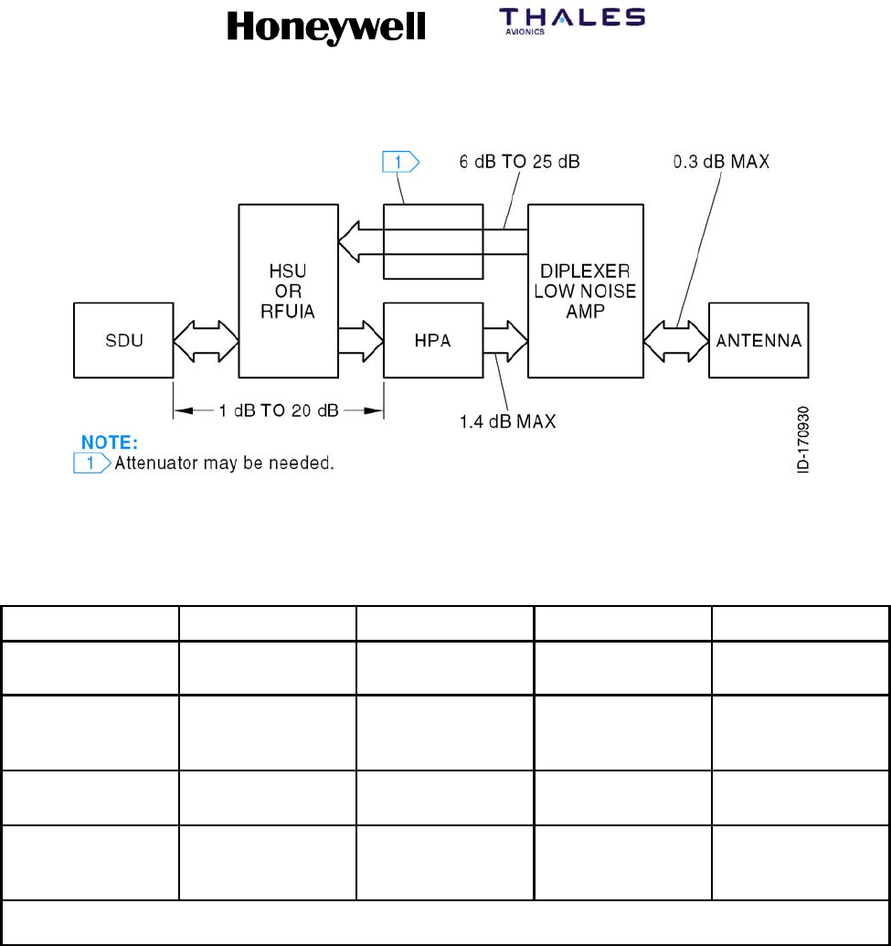
D. Cable Loss Requirements
(1) The attenuation and voltage standing wave ratio (VSWR) of coaxial cable used in the
MCS system must meet the requirements specified in Table 4-1 to make sure the
system operates correctly. Figure 4-1 shows the specific cable attenuations for the
SATCOM equipment. All specified cable attenuations include connector losses, which
are assumed to be 0.1 dB each. Honeywell recommends each cable assembly be
sweep tested for loss and VSWR.
SYSTEM DESCRIPTION, INSTALLATION, AND MAINTENANCE MANUAL
MCS--4200/7200 Multi--Channel SATCOM System
23--20--35 15 Jul 2006
Honeywell International Inc. Do not copy without express permission of Honeywell.
Page 4--3
Figure 4-1. Cable Attenuations
Table 4-1. Cable Loss Requirements
Cable Assembly Location Minimum Loss Maximum Loss Maximum VSWR
TX Cable Between SDU,
HSU and HPA
1dB 20 dB 2.0
RX Cable Between
Diplexer/LNA and
SDU
6dB 25 dB 2.0
TX Cable Between HPA and
Diplexer/LNA
N/A 1.4 dB
(See Note)
1.3
RF Cable Between
Diplexer/LNA and
Antenna
N/A 0.3 dB 1.3
NOTE: In installations that use a high power relay (HPR), the HPR loss must be included. The maximum Tx cable loss
between the HGA and the antenna must not exceed 2.5 dB.
E. Cooling Requirements
(1) The cooling requirements for the MCS avionics are specified in Table 4-2 as follows:
•Power dissipation is in Watts.
•Mass airflow is in pounds per hour.
•CF/M is cubic feet per minute at sea level and 104 °F(40°C).
•Pressure drop is in inches of water.
(2) In most cases, a cooling system that meets the sea level requirements also meets
the cooling requirements at --67 °F(--55°C) and 70,000 feet.

SYSTEM DESCRIPTION, INSTALLATION, AND MAINTENANCE MANUAL
MCS--4200/7200 Multi--Channel SATCOM System
23--20--35 15 Jul 2006
Honeywell International Inc. Do not copy without express permission of Honeywell.
Page 4--4
Table 4-2. Cooling Requirements
Power
Dissipation Mass Airflow CF/M Pressure Drop
LRU Max. Nom. Max. Min. Max. Min. Max. Min.
SDU 150 105 96 (44 kg/hr) 73 (33 kg/hr) 23 18 0.25
(6.35 mm)
0.15
(3.81 mm)
HPA
(60W)
425 250 176 (80 kg/hr) 121 (55 kg/hr) 42 29 0.25
(6.35 mm)
0.2
(5.0 mm)
HSU 100 55 63 (29 kg/hr) 49 (22 kg/hr) 15 11 0.25
(6.35 mm)
0.15
(3.81 mm)
NOTE: The SDU draws an additional 20 W during the first 10 minutes (maximum) of operation at 25 _C because of the
oven controlled crystal oscillator (OCXO). The OCXO continuously dissipates this additional 20 W at --55 _C.
F. Vendor Supplied Equipment
(1) Installation equipment like mounting trays, connectors, and cables can be obtained
from various vendors. Refer to Appendix A for additional information about vendor
manufactured equipment. For vendor supplied avionics, refer to the vendor
documentation.
SYSTEM DESCRIPTION, INSTALLATION, AND MAINTENANCE MANUAL
MCS--4200/7200 Multi--Channel SATCOM System
23--20--35 15 Jul 2006
Honeywell International Inc. Do not copy without express permission of Honeywell.
Page 4--5/4--6
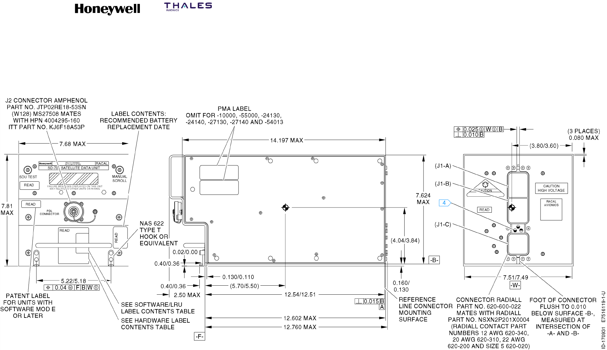
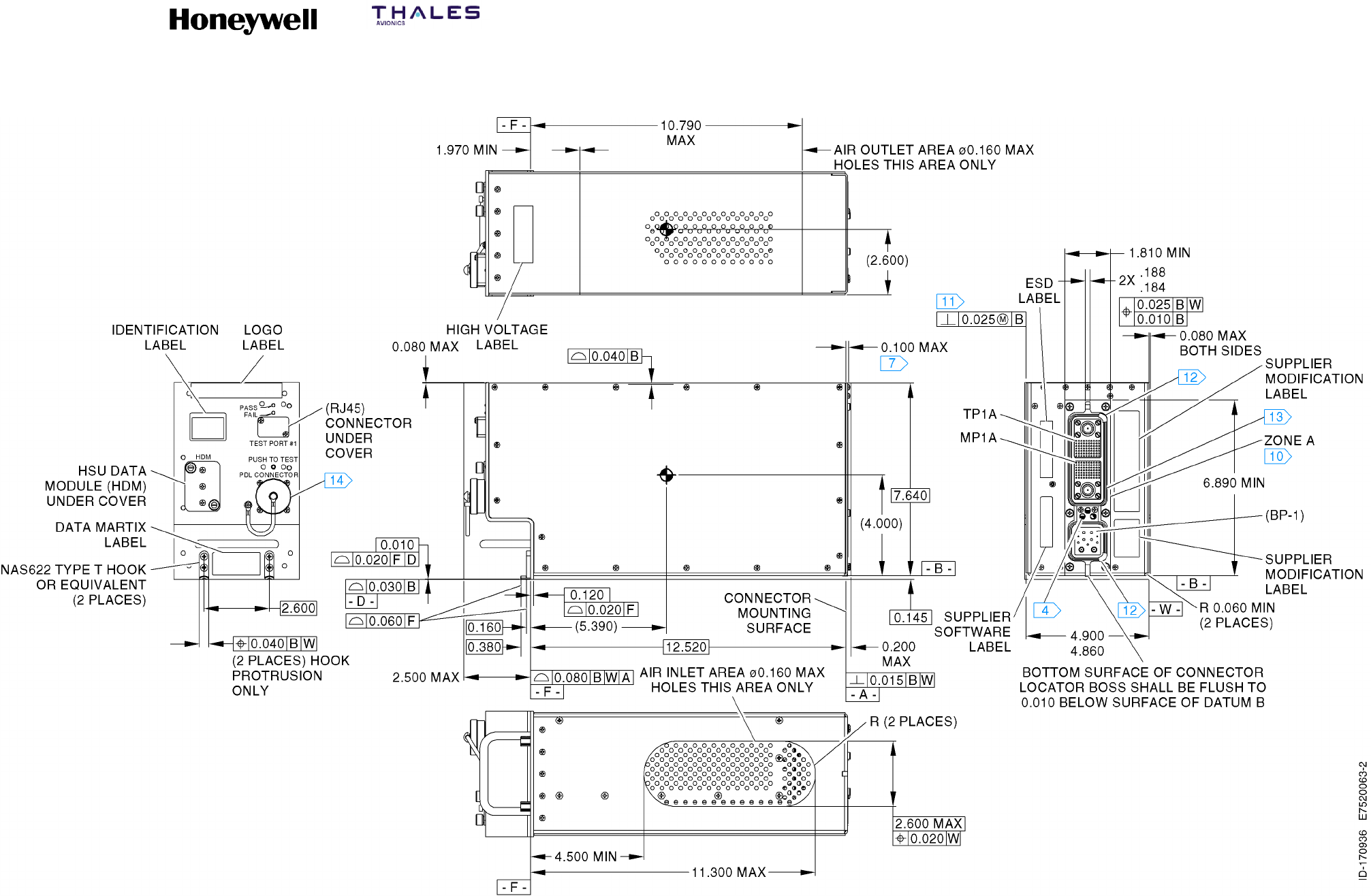
Figure 4-2. SD-700 and SD-720 (7516119) Outline and Installation Diagram
SYSTEM DESCRIPTION, INSTALLATION, AND MAINTENANCE MANUAL
MCS--4200/7200 Multi--Channel SATCOM System
23--20--35 15 Jul 2006
Honeywell International Inc. Do not copy without express permission of Honeywell.
Page 4--7/4--8
NOTES:
1. This assembly includes components which are subject
to damage by electrostatic charges: Therefore all
components shall be handled in accordance with
guidelines for electrostatic discharge control.
2. Unit Weight:
Nominal: 28.0 pounds (12.70 kilograms).
Maximum: 32.0 pounds (14.50 kilograms).
3. Denotes approximate center of gravity.
4. Darkened portion indicates raised part of polarizing keyway.
5. This installation is in accordance with ARINC 600--12 Number 8 MCU.
6. Dimensions are in inches. See the Metric Conversion Table for corresponding
dimensions in millimeters.
7. Cooling airflow requirements:
Minimum: 0.25 ±0.05 inches of water (6.35 ±1.27 millimeters of water) at a flow rate
of 176.4 ±2.0 pounds per hour (80.00 ±0.91 kilograms per hour).
8. Unit finish: gold chemical film.
9. This unit defines 7520000--XXYYY.
XX = Hardware dash number 1 thru 99
YYY = Software Part No. 001 through 999.
10. 0.10 maximum rear panel thickness is required in connector mounting area defined
as zone A. No other projections except connector mounting hardware are permitted
in area defined as zone A.
11. Applies 0.750 from datum B.
12. Electrostatic dust covers shown partially removed for clarity.
13. ARINC 600 connector, receptacle, size 2
Unit Part No.: Radiall NSXFR221Y0908. Tray mating plug Part No. Radiall
NSX2P221X0008.
ARINC 600 connector contact Radiall Part Nos.:
Size 22: Unit Part No. 620--361, tray mating Part No. 620--200.
Size 20: Unit Part No. 620--210, tray mating Part No. 620--310.
Size 12: Unit Part No. 620--240, tray mating Part No. 620--340.
Size 1 coax: Unit Part No. 620--044, see SDIM for tray mating contact Part No.
Size 5 coax: Unit Part No. 620--134, see SDIM for tray mating contact Part No.
14. ARINC 615 connector (PDL):
Unit connector Honeywell Part No. 4008114--160 or MS27508E18B53S, mating
connectors Honeywell Part No. 4004295--160 or ITT Part No. KJ6F18A53P.
METRIC CONVERSION TABLE
INCHES MILLIMETERS
.010 0.254
.015 0.381
.020 0.508
.025 0.635
.030 0.762
.040 1.016
.060 1.524
.080 2.032
.100 2.240
.120 3.048
.145 3.683
.160 4.064
.184 4.674
.188 4.775
.200 5.080
.380 9.652
.750 19.050
1.400 35.560
1.810 45.974
1.970 50.038
2.500 63.500
3.590 91.186
4.500 114.300
5.310 134.874
5.750 146.050
6.890 175.006
7.640 194.056
7.800 198.120
10.070 255.778
10.110 256.794
10.790 274.066
11.300 287.020
12.520 318.008
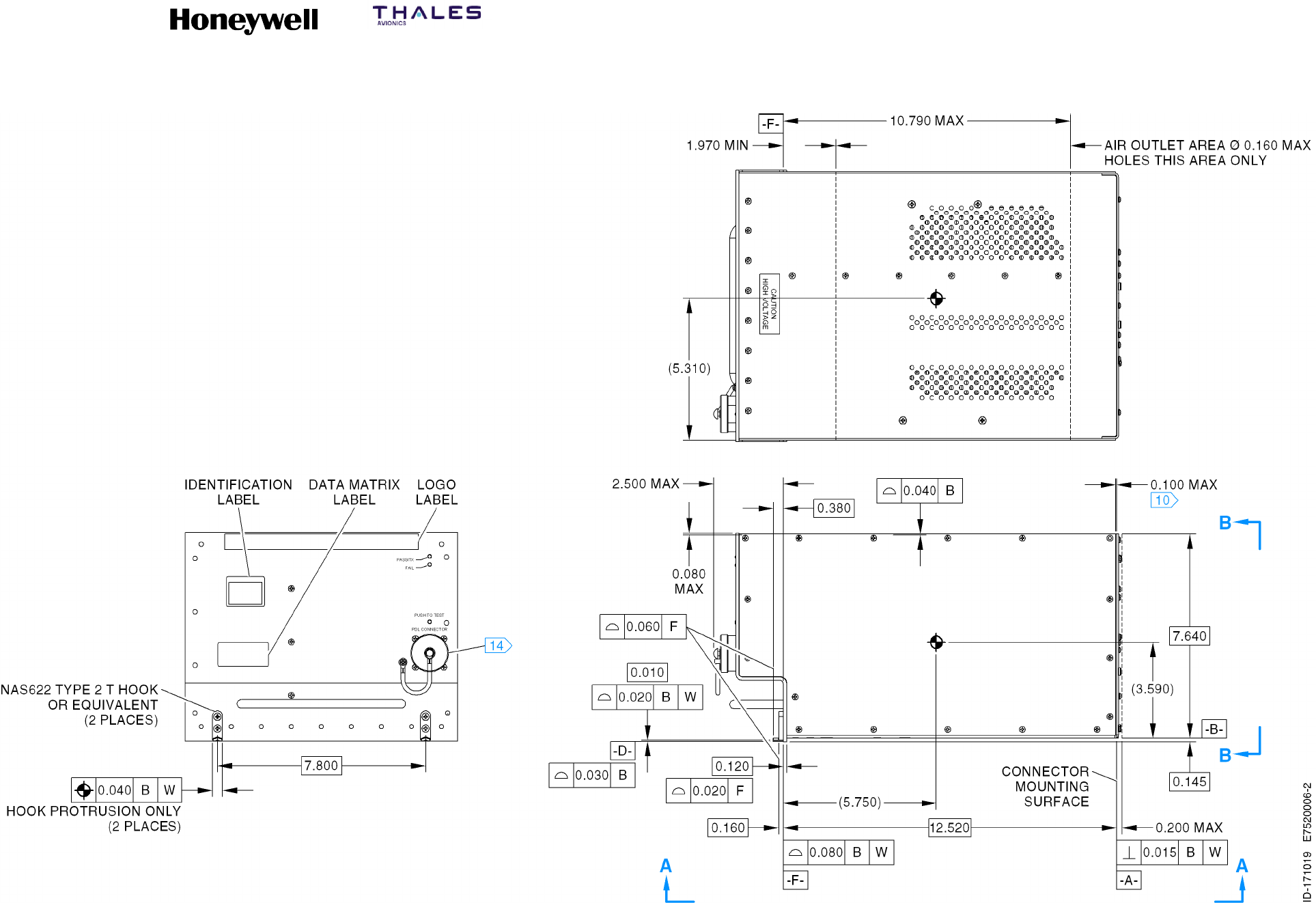
Figure 4-3 (Sheet 1). HP--720 (7520006) Outline and Installation Diagram
6
SYSTEM DESCRIPTION, INSTALLATION, AND MAINTENANCE MANUAL
MCS--4200/7200 Multi--Channel SATCOM System
23--20--35 15 Jul 2006
Honeywell International Inc. Do not copy without express permission of Honeywell.
Page 4--9/4--10
Figure 4-3 (Sheet 2). HP--720 (7520006) Outline and Installation Diagram
SYSTEM DESCRIPTION, INSTALLATION, AND MAINTENANCE MANUAL
MCS--4200/7200 Multi--Channel SATCOM System
23--20--35 15 Jul 2006
Honeywell International Inc. Do not copy without express permission of Honeywell.
Page 4--11/4--12
Figure 4-3 (Sheet 3). HP--720 (7520006) Outline and Installation Diagram
SYSTEM DESCRIPTION, INSTALLATION, AND MAINTENANCE MANUAL
MCS--4200/7200 Multi--Channel SATCOM System
23--20--35 15 Jul 2006
Honeywell International Inc. Do not copy without express permission of Honeywell.
Page 4--13/4--14
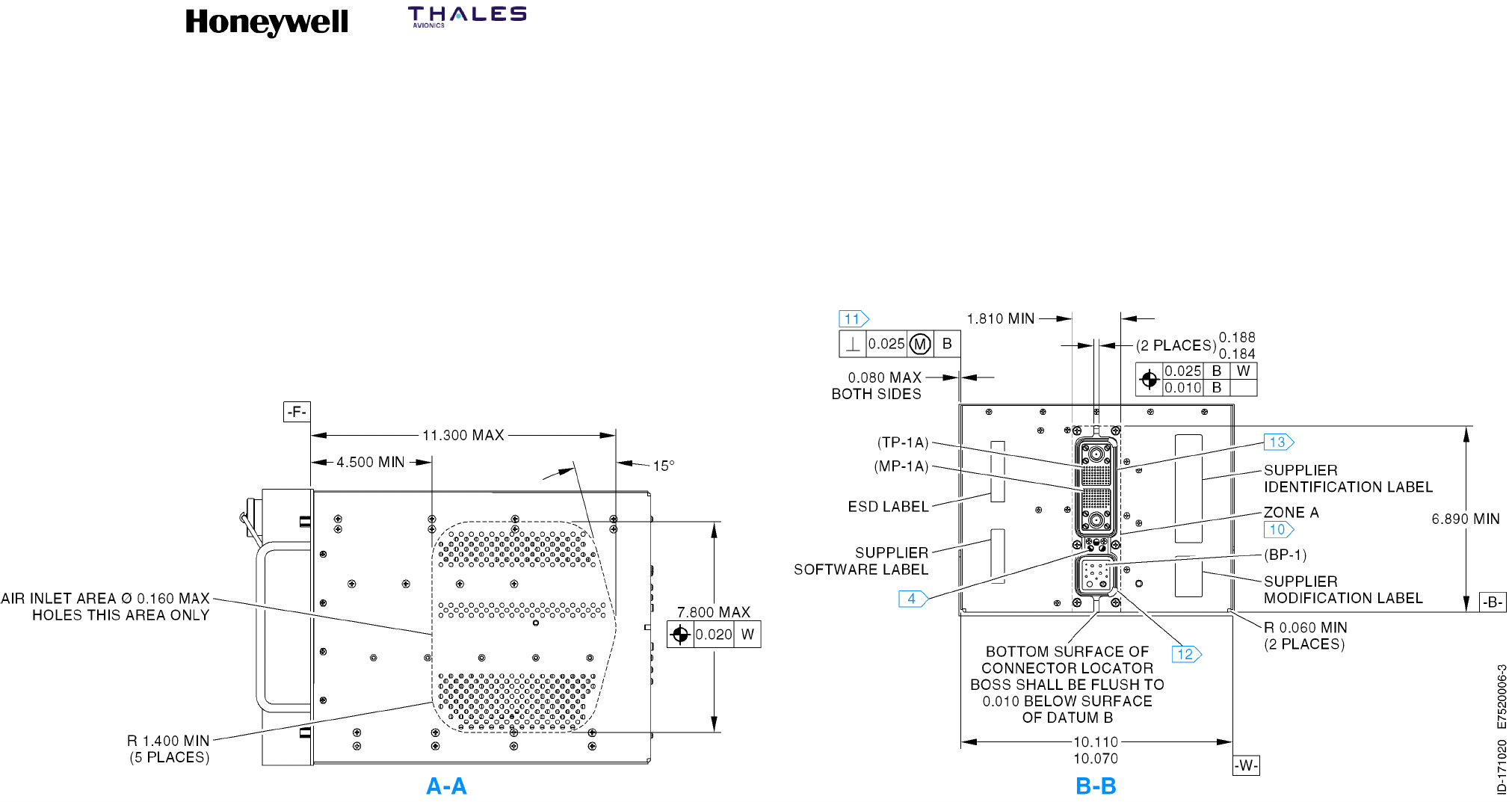
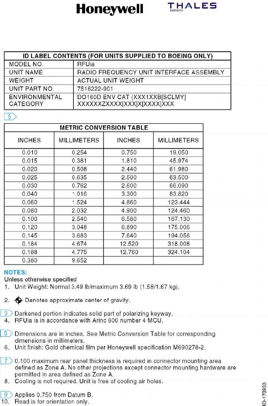
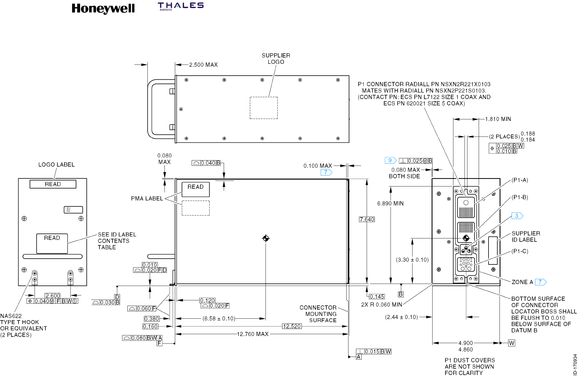
Figure 4-4 (Sheet 1). RFUIA Outline and Installation Diagram
SYSTEM DESCRIPTION, INSTALLATION, AND MAINTENANCE MANUAL
MCS--4200/7200 Multi--Channel SATCOM System
23--20--35 15 Jul 2006
Honeywell International Inc. Do not copy without express permission of Honeywell.
Page 4--15/4--16
Figure 4-4 (Sheet 2). RFUIA Outline and Installation Diagram
SYSTEM DESCRIPTION, INSTALLATION, AND MAINTENANCE MANUAL
MCS--4200/7200 Multi--Channel SATCOM System
23--20--35 15 Jul 2006
Honeywell International Inc. Do not copy without express permission of Honeywell.
Page 4--17/4--18
NOTES:
1. This assembly includes components which are subject
to damage by electrostatic charges: Therefore all
components shall be handled in accordance with
guidelines for electrostatic discharge control.
2. Unit Weight:
Nominal: 15.4 pounds (6.98 kilograms).
Maximum: 16.0 pounds (7.26 kilograms).
3. Denotes approximate center of gravity.
4. Darkened portion indicates raised part of polarizing keyway.
5. This installation is in accordance with ARINC 600--12 Number 4 MCU.
6. Dimensions are in inches. See the Metric Conversion Table for corresponding
dimensions in millimeters.
7. Cooling airflow requirements:
Minimum: 0.15 ±0.05 inches of water (13.81 ±1.27 millimeters of water) at a flow
rate of 49.5 ±2.0 pounds per hour (22.00 ±0.91 kilograms per hour). For added
reliability the following may be used: 0.25 ±0.05 inches of water (6.35 ±1.27
millimeters of water) at a flow rate of 63.1 ±2.0 pounds per hour (28.62 ±0.91
kilograms per hour).
8. Unit finish: gold chemical film.
9. This unit defines 7520061--XXYYY.
XX = Hardware dash number 1 thru 99
YYY = Software Part No. 001 through 999.
10. 0.10 maximum rear panel thickness is required in connector mounting area defined
as zone A. No other projections except connector mounting hardware are permitted
in area defined as zone A.
11. Applies 0.750 from datum B.
12. Electrostatic dust covers shown partially removed for clarity.
13. ARINC 600 connector, receptacle, size 2
Unit Part No.: Radiall NSXFR221Y0903. Tray mating plug Part No. Radiall
NSX2P221X0003.
ARINC 600 connector contact Radiall Part Nos.:
Size 22: Unit Part No. 620--361, tray mating Part No. 620--200.
Size 20: Unit Part No. 620--210, tray mating Part No. 620--310.
Size 12: Unit Part No. 620--240, tray mating Part No. 620--340.
Size 1 coax: Unit Part No. 620--044, see SDIM for tray mating contact Part No.
Size 5 coax: Unit Part No. 620--134, see SDIM for tray mating contact Part No.
14. ARINC 615 connector (PDL):
Unit connector Honeywell Part No. 4008114--160 or MS27508E188535, mating
connectors Honeywell Part No. 4004295--160 or ITT Part No. KJ6F18A53P.
METRIC CONVERSION TABLE
INCHES MILLIMETERS
.010 0.254
.015 0.381
.020 0.508
.025 0.635
.030 0.762
.040 1.016
.060 1.524
.080 2.032
.100 2.240
.120 3.048
.145 3.683
.160 4.064
.184 4.674
.188 4.775
.200 5.080
.380 9.652
.750 19.050
1.810 45.974
1.970 50.038
2.500 63.500
2.600 66.040
4.000 101.600
4.500 114.300
4.860 123.444
4.900 124.460
5.390 136.906
6.890 175.006
7.640 194.056
10.790 274.066
11.300 287.020
12.520 318.008
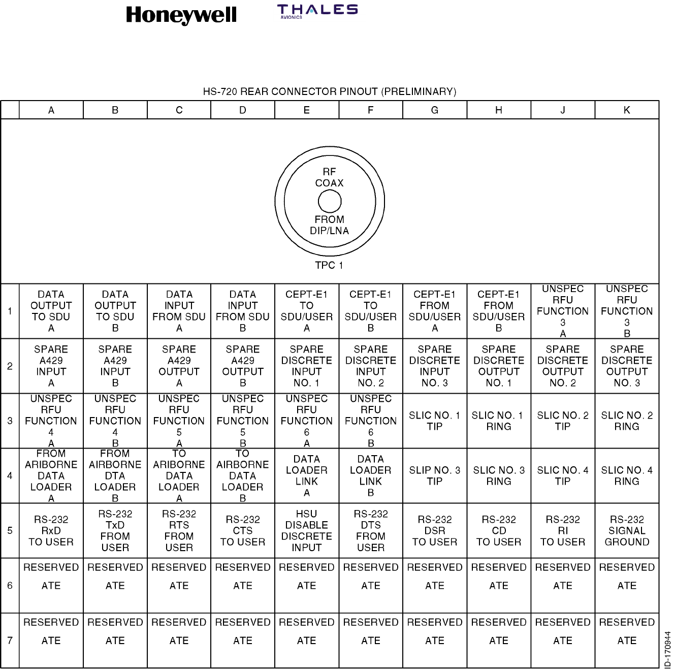
Figure 4-5 (Sheet 1). HS--720 (7520063) Outline and Installation Diagram
6
SYSTEM DESCRIPTION, INSTALLATION, AND MAINTENANCE MANUAL
MCS--4200/7200 Multi--Channel SATCOM System
23--20--35 15 Jul 2006
Honeywell International Inc. Do not copy without express permission of Honeywell.
Page 4--19/4--20
Figure 4-5 (Sheet 2). HS--720 (7520063) Outline and Installation Diagram

SYSTEM DESCRIPTION, INSTALLATION, AND MAINTENANCE MANUAL
MCS--4200/7200 Multi--Channel SATCOM System
23--20--35 15 Jul 2006
Honeywell International Inc. Do not copy without express permission of Honeywell.
Page 5--1
SECTION 5
ELECTRICAL INSTALLATION
1. Overview
A. General
(1) This section supplies electrical installation procedures, power distribution, and
interconnect diagrams for each component of the MCS system.
2. Equipment and Materials
A. General
(1) None.
3. Electrical Installation Procedure
A. Connector Layout and Contact Arrangement
(1) Each front panel connector of the SDU, HSU, and HPA complies with ARINC
characteristic 615, and is used to interface the LRU with an ARINC 615 portable data
loader for software uploads. Pin callouts are specified in Table 5-1. See the
MECHANICAL INSTALLATION section for specifics regarding connector part
numbers for the ARINC 615 connector for each LRU and the corresponding mating
connector.
(2) Table 5-2 lists the pin arrangements for the RJ--45 jack for the Ethernet Port 1. When
a user terminal is connected to this jack, the rear connectors are disconnected so
only the Ethernet Port 1 communications are available from this interface.
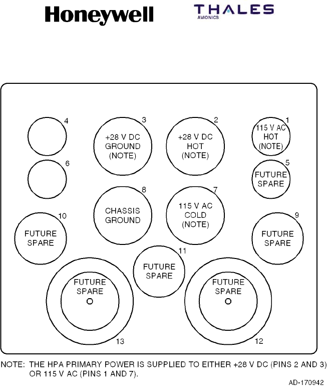
(3) The rear connectors of the SDU, HPA, RFUIA, and HSU comply with ARINC
characteristic 600 as specified in Table 5-3. The ARINC 600 connector layouts and
contact arrangement for the various connector plugs for each LRU of the MCS
system are shown in Figure 5-1 thru Figure 5-11.
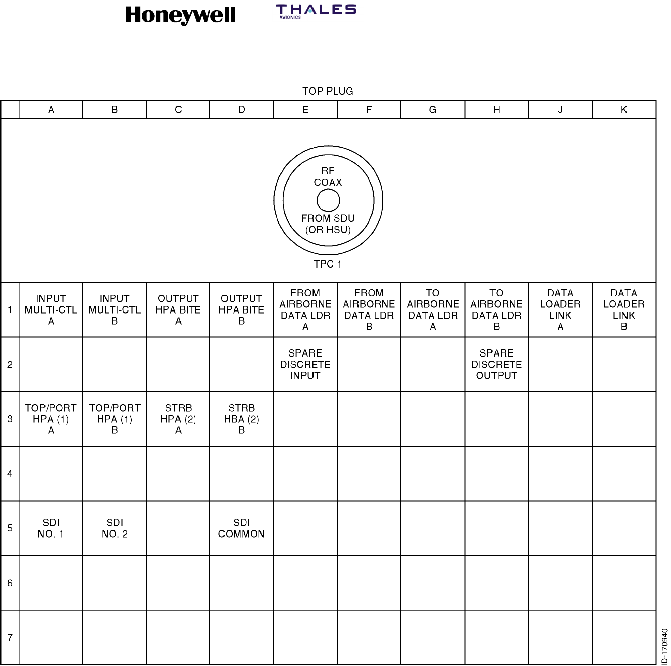
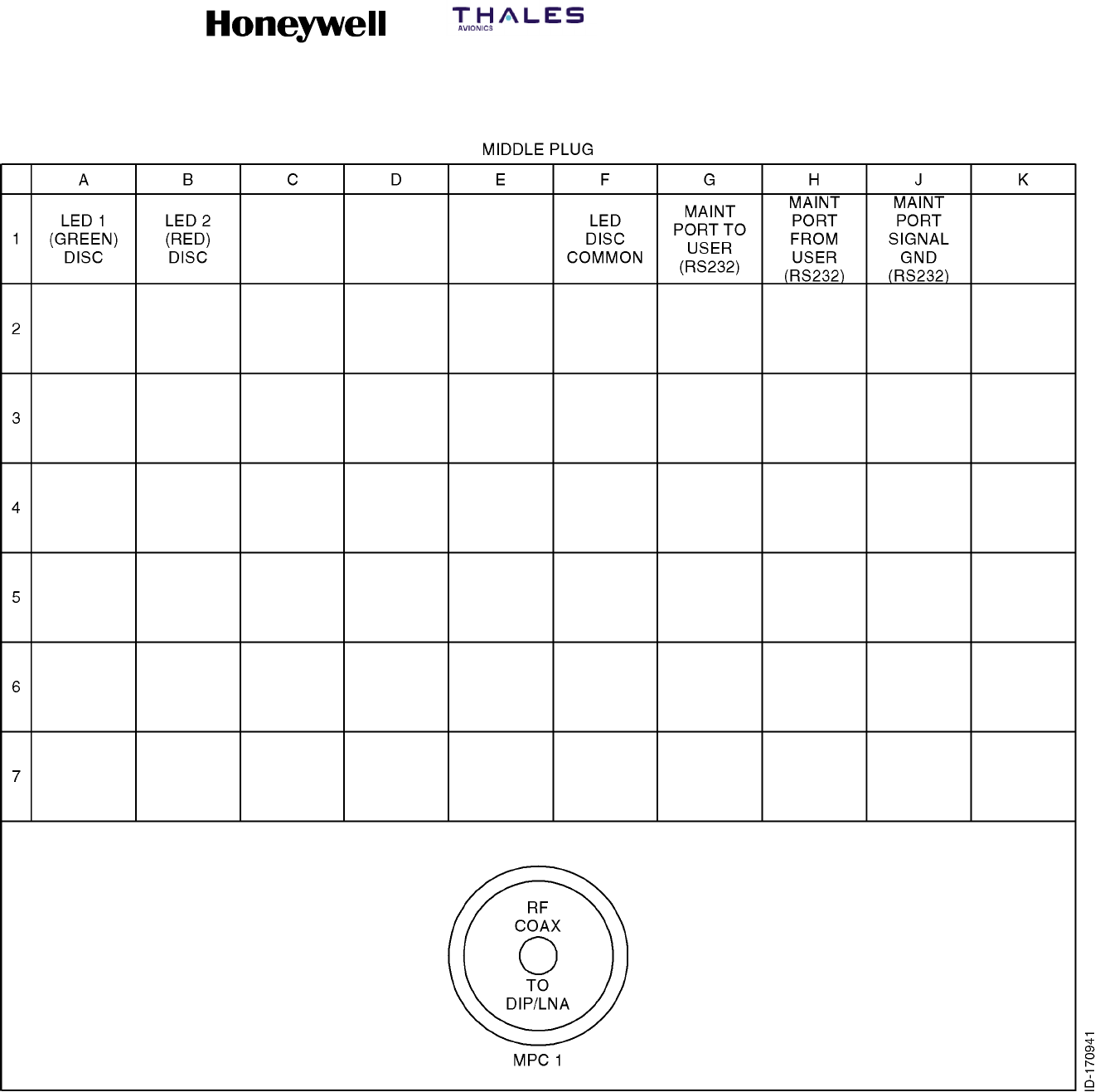
(4) Table 5-4 and Table 5-5 list the contact arrangements for the top and middle inserts
for the SDU ARINC 600 connector. Table 5-6 lists the ICAO Block Strapping.

SYSTEM DESCRIPTION, INSTALLATION, AND MAINTENANCE MANUAL
MCS--4200/7200 Multi--Channel SATCOM System
23--20--35 15 Jul 2006
Honeywell International Inc. Do not copy without express permission of Honeywell.
Page 5--2
Table 5-1. ARINC 615 Connector Pin Callouts
Pin SDU Signal Name HSU Signal Name HPA Signal Name
1PDL 429 A IN PDL 429 A IN PDL TO HPA 429 A
2PDL 429 B IN PDL 429 B IN PDL TO HPA 429 B
5SHIELD GND SHIELD GND SHIELD GND
8PDL 429 A OUT PDL 429 A OUT HPA TO PDL 429 A
9PDL 429 B OUT PDL 429 B OUT HPA TO PDL 429 B
16 SHIELD GND SHIELD GND SHIELD GND
18 PDL LINK A PDL LINK A PDL LINK A
19 GND (PDL LINK B) GND (PDL LINK B) GND (PDL LINK B)
20 115 VAC HOT 115 VAC HOT 115 VAC HOT
21 CHASSIS GND CHASSIS GND CHASSIS GND
22 115 VAC GND 115 VAC GND 115 VAC GND
37 -- -- 28 V DC OUTPUT 28 V DC OUTPUT
38 -- -- 28 V DC RETURN 28 V DC RETURN
40 RS232 A RX--DLT -- -- -- --
41 RS232 A TX--DLT -- -- -- --
42 RS232 B RX--CMT RS232 TO HSU RS232 TO HPA
43 RS232 B TX--CMT RS232 TO DEBUG RS232 TO DEBUG
48 LOGIC COMMON GND LOGIC COMMON GND LOGIC COMMON GND
49 LOGIC COMMON GND LOGIC COMMON GND LOGIC COMMON GND
Table 5-2. HSU Front Panel RJ--45 Pin Arrangements
RJ--45 Connector Pin Pin Name Signal Name
1TX + RJ--45 from User (+)
2TX -- RJ--45 from User (--)
3RX + RJ--45 to User (+)
6RX -- RJ--45 to User (--)

SYSTEM DESCRIPTION, INSTALLATION, AND MAINTENANCE MANUAL
MCS--4200/7200 Multi--Channel SATCOM System
23--20--35 15 Jul 2006
Honeywell International Inc. Do not copy without express permission of Honeywell.
Page 5--3
Table 5-3. ARINC 600 Connector Requirements
LRU Connector Description
LRU Rear
Connector Part
No.
Rack Mounting
Connector Part No. Outline Diagram
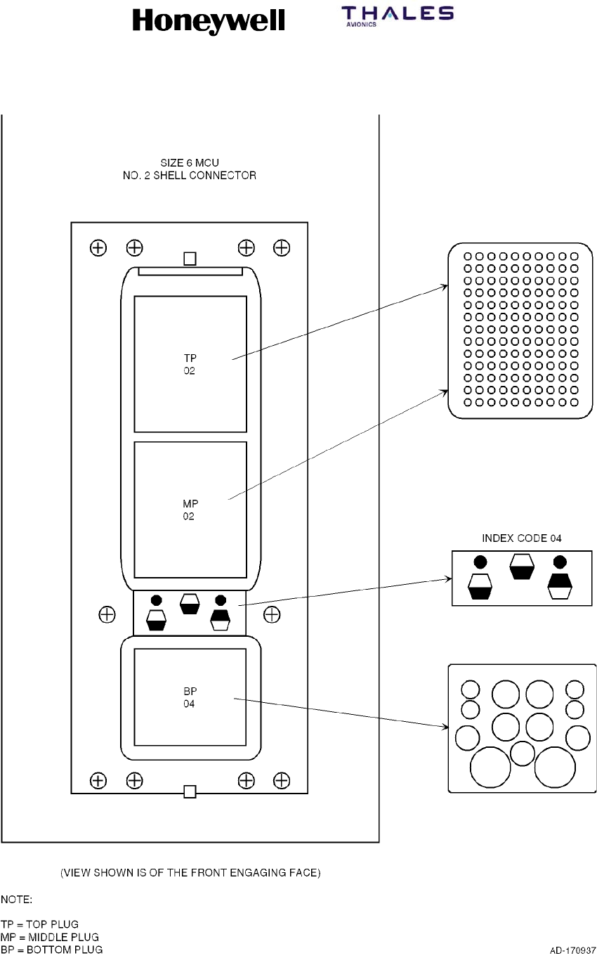
SDU ARINC 600 -- Size 6
MCU No. 2 Shell
•Type 02 Top Insert
•Type 02 Middle Insert
•Type 04 Bottom Insert
•Index Pin Code 04
620--600--022
(Radiall)
NSXN2P201X0004
(Radiall)
Figure 4-2,
Figure 5-1,
Figure 5-2,
Table 5-4, and
Table 5-5
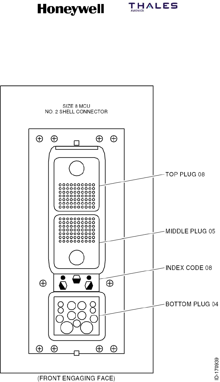
HPA
(60 W)
ARINC 600 -- Size 8
MCU No. 2 Shell
•Type 08 Top Insert
•Type 05 Middle Insert
•Type 04 Bottom Insert
•Index Pin Code 08
620--600--076
(Radiall)
NSXN2P221X0008
(Radiall)
Figure 4-3
Figure 5-3 thru
Figure 5-6
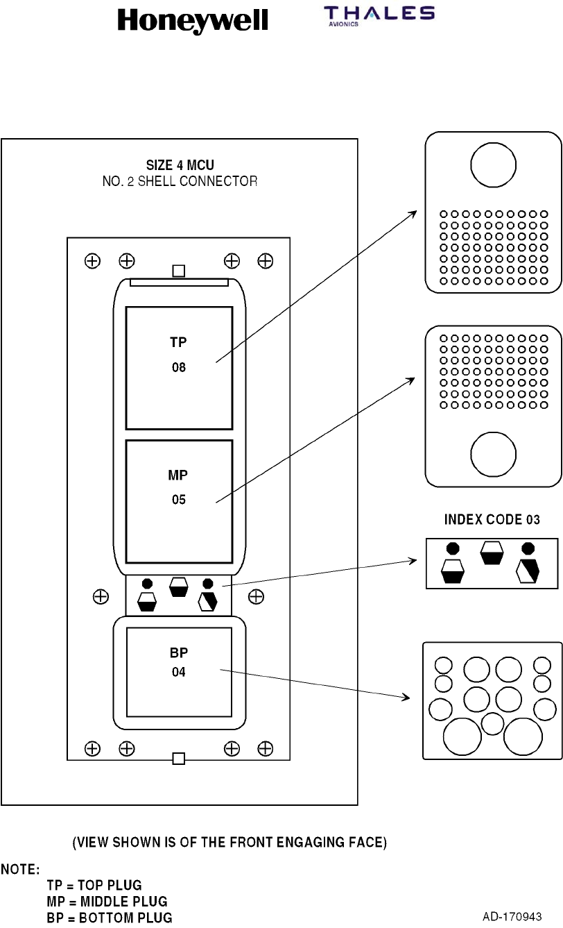
RFUIA ARINC 600 -- Size 4
MCU No. 2 Shell
•Type 08 Top Insert
•Type 05 Middle Insert
•Type 04 Bottom Insert
•Index Pin Code 03
NSXNR221X0103
(Radiall)
NSXNP221S0103
(Radiall)
Figure 4--4
Figure 5-11
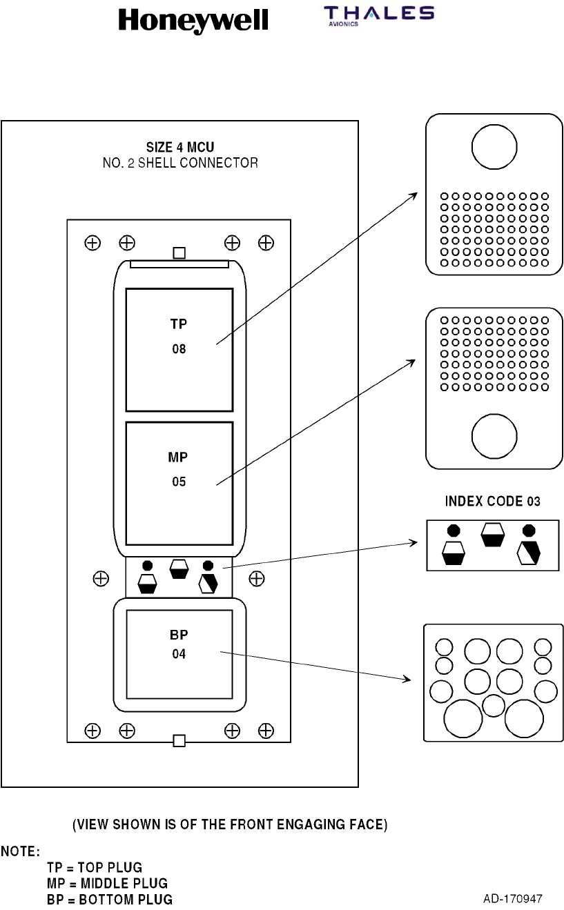
HSU ARINC 600-- Size 4
MCU No. 2 shell
•Type 08 Top Insert
•Type 05 Middle Insert
•Type 04 Bottom Insert
•Index Pin Code 03
620--600--075
(Radiall)
NSXN2P221X0003
(Radiall)
Figure 4--5
Figure 5--7 thru
Figure 5--10
SYSTEM DESCRIPTION, INSTALLATION, AND MAINTENANCE MANUAL
MCS--4200/7200 Multi--Channel SATCOM System
23--20--35 15 Jul 2006
Honeywell International Inc. Do not copy without express permission of Honeywell.
Page 5--4
Figure 5-1. SDU ARINC 600 Connector Layout

SYSTEM DESCRIPTION, INSTALLATION, AND MAINTENANCE MANUAL
MCS--4200/7200 Multi--Channel SATCOM System
23--20--35 15 Jul 2006
Honeywell International Inc. Do not copy without express permission of Honeywell.
Page 5--5
Table 5-4. Contact Arrangements for Top Insert, SDU ARINC 600 Connector
A B C D E F G H J K
1
WH--10
CABIN
VOICE
CHANNEL 1
HOOK--
SWITCH
WH--10
CABIN
VOICE
CHANNEL 2
HOOK--
SWITCH
WH10--1
STATUS
A
(RINGER)
WH10--1
STATUS
B
(RINGER)
WH10--2
STATUS
A
(RINGER)
WH10--2
STATUS
B
(RINGER)
AVIONICS
SUB--
SYSTEM
SATCOM
FAIL
WARNING
(NON MCS
FAIL)
WH--10
CABIN VOICE
CHANNEL 1
IN--USE
SATELLITE
LINK NOT
READY
WH--10
CABIN
VOICE
CHANNEL 2
IN--USE
2
ANALOG
PBX
CHANNEL 1
INPUT HI
ANALOG
PBX
CHANNEL 1
INPUT LO
ANALOG
PBX
CHANNEL 1
OUTPUT HI
ANALOG
PBX
CHANNEL 1
OUTPUT LO
ANALOG
PBX
CHANNEL 2
INPUT HI
ANALOG
PBX
CHANNEL 2
INPUT LO
ANALOG
PBX
CHANNEL 2
OUTPUT HI
ANALOG PBX
CHANNEL 2
OUTPUT LO
O O
3
COCKPIT
VOICE UN--
AVAILABLE
CABIN
VOICE UN--
AVAILABLE
PACKET
DATA UN--
AVAILABLE
PACKET
DATA LOW
SPEED ONLY
AVAILABLE
(CD2--2)
SATCOM IN--
OPERABLE
(MCS FAIL)
CEPT--E1
0V SHIELD
(GND)
CEPT--E1 to
BRIDGED
CTU
(CM--250) 1A
CEPT--E1 to
BRIDGED CTU
(CM--250) 1B
CEPT--E1 to
BRIDGED
CTU
(CM--250) 2A
CEPT--E1 to
BRIDGED
CTU
(CM--250) 2B
4RESERVED RESERVED RESERVED RESERVED RESERVED RESERVED RESERVED RESERVED RESERVED CEPT--E1
0V
5RESERVED RESERVED RESERVED RESERVED RESERVED RESERVED RESERVED RESERVED RESERVED RESERVED
6RESERVED RESERVED SPARE 429
OUTPUT A
SPARE 429
OUTPUT B RESERVED RESERVED RESERVED RESERVED RESERVED SPARE
7RESERVED RESERVED SPARE RESERVED RESERVED RESERVED RESERVED RESERVED RESERVED RESERVED
8RESERVED RESERVED RESERVED RESERVED RESERVED RESERVED RESERVED RESERVED SPARE SPARE
9
SPARE
DISCRETE
INPUT
CONFIG
STRAP TYPE
SPARE
DISCRETE
INPUT
CONFIG
STRAP TYPE
SPARE RESERVED RESERVED RESERVED RESERVED RESERVED RESERVED SPARE
10
AVAIL OF
429 SSR
MODE S
ADDRESS
RESERVED
FOR FMC
CONFIG
RESERVED
FOR FMC
CONFIG
CMU
BUS
SPEED
CPDF
CONFIG
AES ID
BUS SPEED
HSU #1
PRESENCE
SDU
CONTROLLER
TYPE
RESERVED
FOR STRAP
OPTION
CALL LIGHT
ACTIVATOR
CONFIGU--
RATION
11
STRAP
PARITY
(ODD)
CCS
PRESENCE
IRS
CONFIG
IRS
CONFIG
HPR/HPA/
BSU/LGA
CONFIG
HPR/HPA/
BSU/LGA
CONFIG
HPR/HPA/
BSU/LGA
CONFIG
HPR/HPA/
BSU/LGA
CONFIG
HPR/HPA/
BSU/LGA
CONFIG
HPR/HPA/
BSU/LGA
CONFIG
12 CFDS/CMC
TYPE
CFDS/CMC
TYPE
CFDS/CMC
TYPE
RESERVED
CONFIG
SDU
CONFIG
SDU
NUMBER
CMU
NO. 1
CONFIG
CMU
NO. 2 CONFIG
WSC/
MCDU/
NO. 1
CONFIG
WSC/
MCDU/
NO. 2
CONFIG
13 PRIORITY
4 CALLS
MCDU/
BUS SPEED
LIGHT/
CHIME
CODE
LIGHT/
CHIME
CODE
WSC/
MCDU/
NO. 3
CONFIG
SDU
CODEC 1
WIRING
SDU
CODEC 1
WIRING
SDU
CODEC 2
WIRING
SDU
CODEC 2
WIRING
COCKPIT
SIGNALING
METHOD
14 5V
POS_MON
9V
POS_MON
RESERVED
ATE
RESET--
MON_N PEIT_SEL_N RESERVED
ATE
RS--232
INPUT FROM
HSU
RS--232
OUTPUT TO
HSU
CEPT--E1
FROM
BRIDGED
CTU
(CM--250)1A
CEPT--E1
FROM
BRIDGED
CTU
(CM--250)1B
15 15 V
POS_MON
15 V
NEG_MON
GND (ATE
COMMON)
CEPT--E1
FROM
BRIDGED
CTU
(CM--250) 2A
CEPT--E1
FROM
BRIDGED
CTU
(CM--250) 2B
DLT_RX
(RS232
RX--SDU)
DLT_TX
(RS232
TX--SDU)
CMT_RX
(RS232
RX--SDU)
CMT_TX
(RS232
TX--SDU)
CMT_DLT_
RTN

SYSTEM DESCRIPTION, INSTALLATION, AND MAINTENANCE MANUAL
MCS--4200/7200 Multi--Channel SATCOM System
23--20--35 15 Jul 2006
Honeywell International Inc. Do not copy without express permission of Honeywell.
Page 5--6
Table 5-5. Contact Arrangements for Middle Insert, SDU ARINC 600 Connector
A B C D E F G H J K
1
WH10 CABIN
NO. 1
AUDIO IN HI
WH10 CABIN
No. 1
AUDIO IN LO
WH10 CABIN
No. 1
AUDIO OUT
HI
WH10 CABIN
No. 1
AUDIO OUT
LO
DATA BUS
FROM CABIN
PACKET DATA
A
DATA BUS
FROM CABIN
PACKET
DATA B
FROM CMU
NO. 1
429
A
FROM CMU
NO. 1
429
B
TO CMU
NO. 1 AND
NO. 2
429 A
TO CMU
NO. 1 AND
NO. 2
429 B
2
COCKPIT
AUDIO CH 1
INPUT HI
COCKPIT
AUDIO CH 1
INPUT LO
COCKPIT
AUDIO CH 1
OUTPUT HI
COCKPIT
AUDIO CH 1
OUTPUT LO
COCKPIT
AUDIO CH 2
INPUT HI
COCKPIT
AUDIO CH 2
INPUT LO
COCKPIT
AUDIO CH 2
OUTPUT HI
COCKPIT
AUDIO CH 2
OUTPUT LO
CEPT--E1
FROM CTU
INPUT A
CEPT--E1
FROM CTU
INPUT B
3
CEPT--E1 TO
CTU OUTPUT
A
CEPT--E1 TO
CTU OUTPUT
B
DATA FROM
MCDU/WSC
NO. 1
A
DATA FROM
MCDU/WSC
NO. 1
B
DATA FROM
MCDU/WSC
NO. 2
A
DATA FROM
MCDU/WSC
NO. 2
B
DATA FROM
CMU
NO. 2
A
DATA FROM
CMU
NO. 2
B
DATA TO
SCDU/WSC
NO. 1,
NO.2,AND
NO. 3
A
DATA TO
SCDU/WSC
NO. 1,
NO.2,AND
NO. 3
B
4
AES
ID
INPUT
A
AES
ID
INPUT
B
FROM
CFDS
A
FROM
CFDS
B
TO
CFDS
A
TO
CFDS
B
MULTI--
CONTROL
OUTPUT
A
MULTI--
CONTROL
OUTPUT
B
WH10 CABIN
NO. 2
AUDIO IN
HI
WH10 CABIN
NO. 2
AUDIO IN
LO
L
G
A
LN
A
W E I G H T -- O N -- W H E E L S WH10 CABIN
N
O
.
2
WH10 CABIN
N
O
.
2
BITE INPUT
FROM LG
A
CHIME/
LIGHT
DUAL
S
Y
STEM
DUAL
S
Y
STEM
5
L
G
A
L
N
A
ON/OFF
CONTROL INPUT
NO. 1
INPUT
NO. 2
PROGRAM
SELECT
N
O
.
2
AUDIO OUT HI
N
O
.
2
AUDIO OUT
LO
F
R
O
M
L
G
A
LNA
L
I
G
H
T
INHIBIT
S
Y
S
T
E
M
SELECT
DISCRETE
I/O
S
Y
S
T
E
M
SELECT
DISCRETE
INHIBIT
6
DATA FROM
PRIMARY
IRS A
DATA FROM
PRIMARY
IRS B
DATA FROM
SECONDARY
IRS A
DATA FROM
SECONDARY
IRS B
BITE INPUT
FROM
HGA/HPA A
BITE INPUT
FROM
HGA/HPA B
SPARE 429
INPUT
A
SPARE 429
INPUT
B
BITE INPUT
FROM
LGA/HPA A
BITE INPUT
FROM
LGA/HPA B
7
DATA BUS
FROM
AIRBORNE
LOADER
A
DATA BUS
FROM
AIRBORNE
LOADER
B
DATA BUS
TO
AIRBORNE
LOADER
A
DATA BUS
TO
AIRBORNE
LOADER
B
RESERVED RESERVED
BITE INPUT
FROM ACU
OR
TOP--PORT
BSU A
BITE INPUT
FROM ACU
OR
TOP--PORT
BSU B
BITE INPUT
FROM STBD
BSU
A
BITE INPUT
FROM STBD
BSU
B
8
DATA
LOADER
LINK A
DATA
LOADER
LINK B
RESERVED
FOR DATA
BUS FROM
RMP A
RESERVED
FOR DATA
BUS FROM
RMP B
CP VOICE
CALL LGT
OUTPUT
NO. 1
(CD1--1)
CP VOICE
MIC ON
INPUT
NO. 1
CP VOICE
CALL LGT
OUTPUT
NO. 2
(CD2--2)
CP VOICE
MIC ON
INPUT
NO. 2
DATA FROM
MCDU/WSC
NO. 3
A
DATA FROM
MCDU/WSC
NO. 3
B
9
DATA BUS
TO SNU OR
CPDF A
DATA BUS
TO SNU OR
CPDF B
RESERVED
FOR DATA
TO RMP A
RESERVED
FOR DATA
TO RMP B
FROM HSU #1
429A
FROM HSU
#1 429B
TO HSU #1
429A TO HSU 429B
CEPT--E1
FROM 0BE1
A
CEPT--E1
FROM 0BE1
B
10 CEPT--E1 TO
0BE1 A
CEPT--E1 TO
0BE1 B RESERVED RESERVED RESERVED
(GND)
RESERVED
(GND)
RESERVED
(GND)
RESERVED
(GND) SPARE SPARE
11
FROM
MOTION
SENSOR
NO. 1
MOTION
SENSOR
NO. 1
PROGRAM
SELECT
CALL
PLACE/END
DISCRETE
INPUT
NO. 1
CALL
PLACE/END
DISCRETE
INPUT
NO. 2
CGU
CONNECTION
CONFIG
COCKPIT
CALL
DISCRETE
SIGNALLING
MODE
RESERVED
UNSPEC
PROGRAM
RESERVED
UNSPEC
PROGRAM
RESERVED
UNSPEC
PROGRAM
STRAP
PARITY
EVEN
12
CROSSTALK
FROM
OTHERSDU
A
CROSSTALK
FROM
OTHERSDU
B
CROSSTALK
TO
OTHERSDU
A
CROSSTALK
TO
OTHERSDU
B
SPARE
O
SPARE
O
RESERVED
FOR DATA
FROM
FMC 1
A
RESERVED
FOR DATA
FROM
FMC 1
B
RESERVED
FOR DATA
FROM
FMC 2
A
RESERVED
FOR DATA
FROM
FMC 2
B
13
HSU #1
DISABLE
DISCRETE
OUT
SPARE
O
ICAO
ADDRESS
BIT NO. 1
(MSB)
ICAO
ADDRESS
BIT NO. 2
ICAO
ADDRESS BIT
NO. 3
ICAO
ADDRESS
BIT NO. 4
ICAO
ADDRESS
BIT NO. 5
ICAO
ADDRESS
BIT NO. 6
ICAO
ADDRESS
BIT NO. 7
ICAO
ADDRESS
BIT NO. 8
14
CP VOICE
GO--AHEAD
CHIME
RESET
CP VOICE
CHIME
CONTACT
1 (CD2--8)
CP VOICE
CONTACT
2
ICAO
ADDRESS
BIT NO. 9
ICAO
ADDRESS BIT
NO. 10
ICAO
ADDRESS
BIT NO. 11
ICAO
ADDRESS
BIT NO. 12
ICAO
ADDRESS
BIT NO. 13
ICAO
ADDRESS
BIT NO. 14
ICAO
ADDRESS
BIT NO. 15
15
ICAO
ADDRESS
BIT NO. 16
ICAO
ADDRESS
BIT NO. 17
ICAO
ADDRESS
BIT NO. 18
ICAO
ADDRESS
BIT NO. 19
ICAO
ADDRESS BIT
NO. 20
ICAO
ADDRESS
BIT NO. 21
ICAO
ADDRESS
BIT NO. 22
ICAO
ADDRESS
BIT NO. 23
ICAO
ADDRESS
BIT NO. 24
(LSB)
ICAO
ADDRESS
COMMON
SYSTEM DESCRIPTION, INSTALLATION, AND MAINTENANCE MANUAL
MCS--4200/7200 Multi--Channel SATCOM System
23--20--35 15 Jul 2006
Honeywell International Inc. Do not copy without express permission of Honeywell.
Page 5--7
Figure 5-2. Contact Arrangements for Bottom Insert, SDU ARINC 600 Connector
SYSTEM DESCRIPTION, INSTALLATION, AND MAINTENANCE MANUAL
MCS--4200/7200 Multi--Channel SATCOM System
23--20--35 15 Jul 2006
Honeywell International Inc. Do not copy without express permission of Honeywell.
Page 5--8
Figure 5-3. HPA ARINC 600 Connector Layout
SYSTEM DESCRIPTION, INSTALLATION, AND MAINTENANCE MANUAL
MCS--4200/7200 Multi--Channel SATCOM System
23--20--35 15 Jul 2006
Honeywell International Inc. Do not copy without express permission of Honeywell.
Page 5--9/5--10
Figure 5-4. Contact Arrangements for the Top Insert 60 Watt HPA ARINC 600 Connector
SYSTEM DESCRIPTION, INSTALLATION, AND MAINTENANCE MANUAL
MCS--4200/7200 Multi--Channel SATCOM System
23--20--35 15 Jul 2006
Honeywell International Inc. Do not copy without express permission of Honeywell.
Page 5--11/5--12
Figure 5-5. Contact Arrangements for Middle Insert, HPA (60 Watt) ARINC 600
SYSTEM DESCRIPTION, INSTALLATION, AND MAINTENANCE MANUAL
MCS--4200/7200 Multi--Channel SATCOM System
23--20--35 15 Jul 2006
Honeywell International Inc. Do not copy without express permission of Honeywell.
Page 5--13
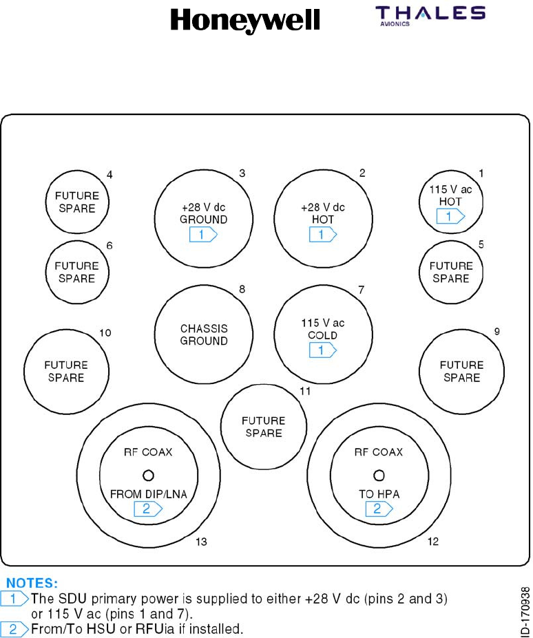
Figure 5-6. Contact Arrangements for Bottom Insert, HPA (60 Watt) ARINC 600 Connector
SYSTEM DESCRIPTION, INSTALLATION, AND MAINTENANCE MANUAL
MCS--4200/7200 Multi--Channel SATCOM System
23--20--35 15 Jul 2006
Honeywell International Inc. Do not copy without express permission of Honeywell.
Page 5--14
Figure 5-7. HS--720 ARINC 600 Connector Layout
SYSTEM DESCRIPTION, INSTALLATION, AND MAINTENANCE MANUAL
MCS--4200/7200 Multi--Channel SATCOM System
23--20--35 15 Jul 2006
Honeywell International Inc. Do not copy without express permission of Honeywell.
Page 5--15/5--16
Figure 5-8. Contact Arrangements for Top Insert, HSU ARINC 600 Connector
SYSTEM DESCRIPTION, INSTALLATION, AND MAINTENANCE MANUAL
MCS--4200/7200 Multi--Channel SATCOM System
23--20--35 15 Jul 2006
Honeywell International Inc. Do not copy without express permission of Honeywell.
Page 5--17/5--18
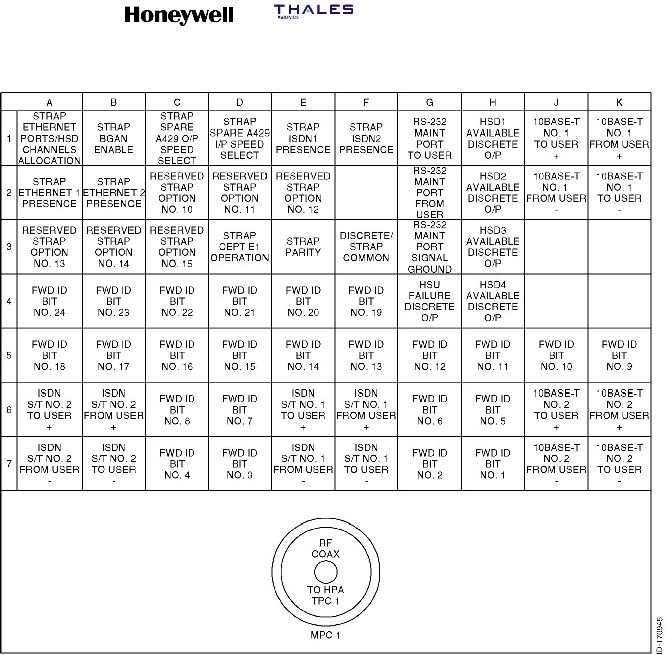
Figure 5-9. Contact Arrangements for the Middle Insert, HSU ARINC 600 Connector
SYSTEM DESCRIPTION, INSTALLATION, AND MAINTENANCE MANUAL
MCS--4200/7200 Multi--Channel SATCOM System
23--20--35 15 Jul 2006
Honeywell International Inc. Do not copy without express permission of Honeywell.
Page 5--19
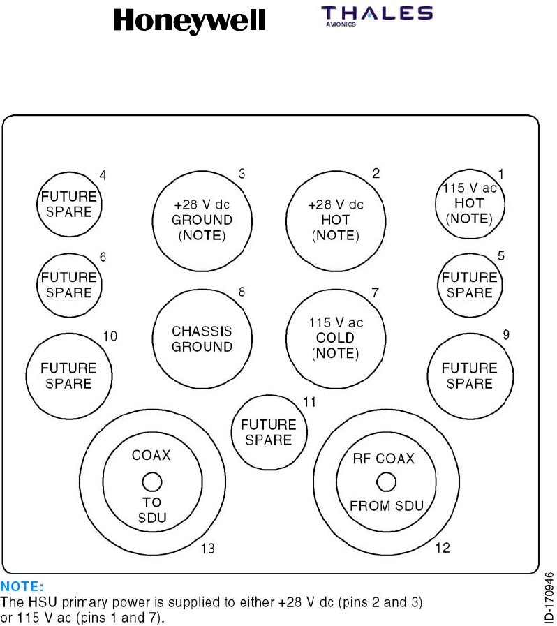
Figure 5-10. Contact Arrangements for the Bottom Insert, HSU ARINC 600 Connector
SYSTEM DESCRIPTION, INSTALLATION, AND MAINTENANCE MANUAL
MCS--4200/7200 Multi--Channel SATCOM System
23--20--35 15 Jul 2006
Honeywell International Inc. Do not copy without express permission of Honeywell.
Page 5--20
Figure 5-11. RFUIA ARINC 600 Connector Layout

SYSTEM DESCRIPTION, INSTALLATION, AND MAINTENANCE MANUAL
MCS--4200/7200 Multi--Channel SATCOM System
23--20--35 15 Jul 2006
Honeywell International Inc. Do not copy without express permission of Honeywell.
Page 5--21
B. Electrical Installation
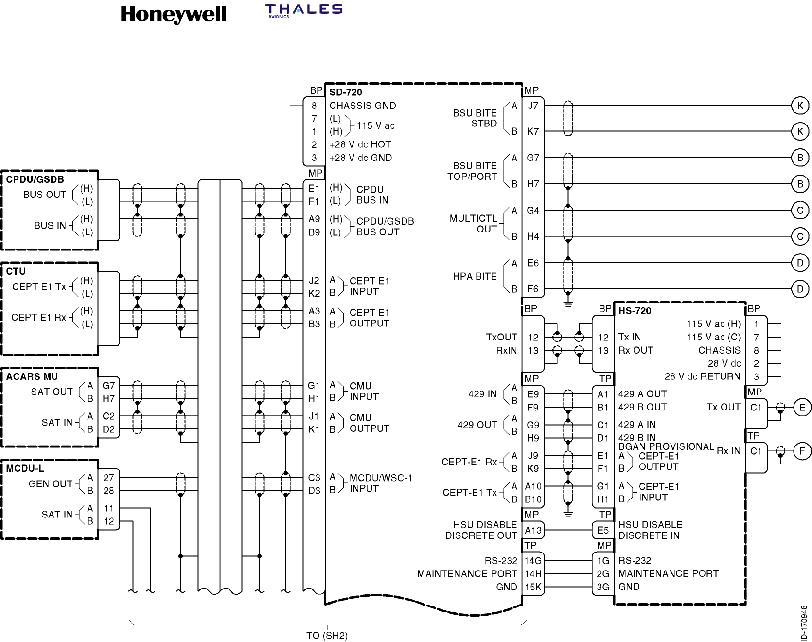
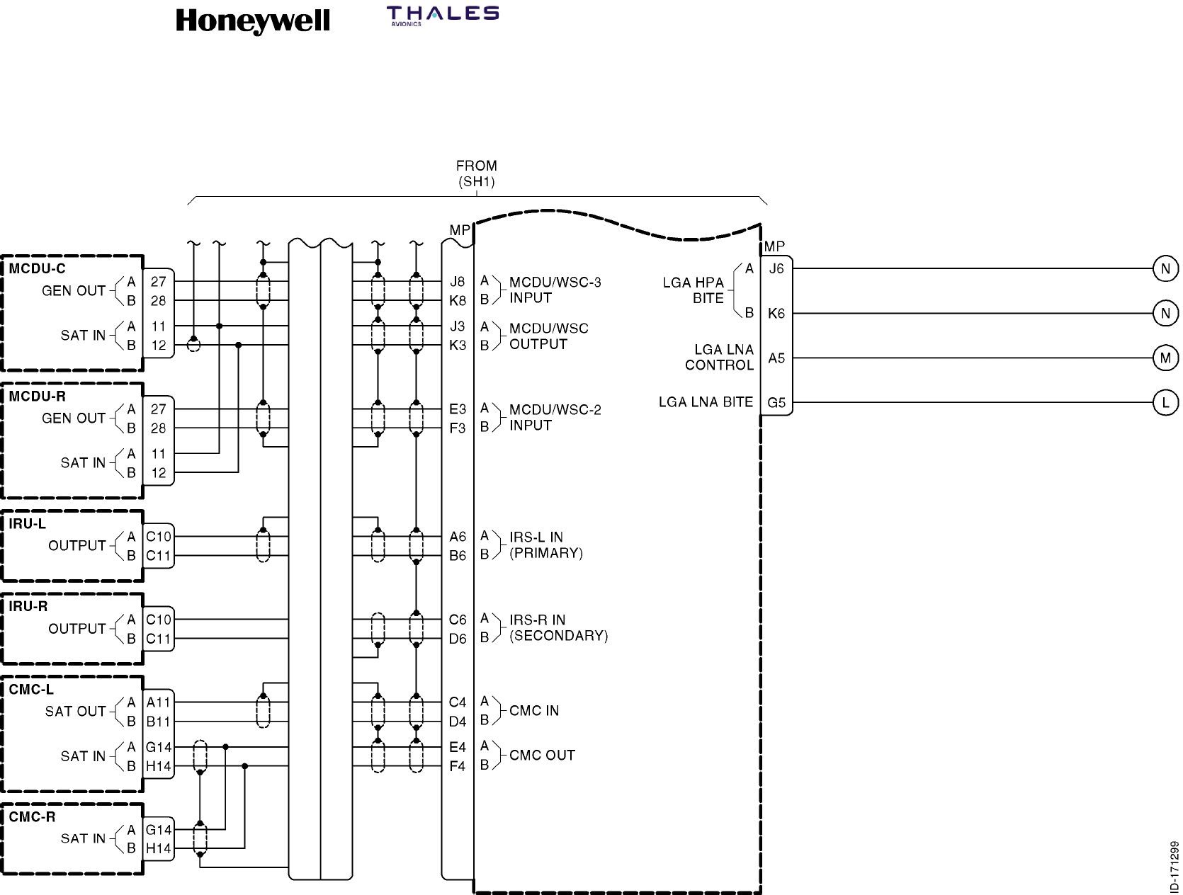
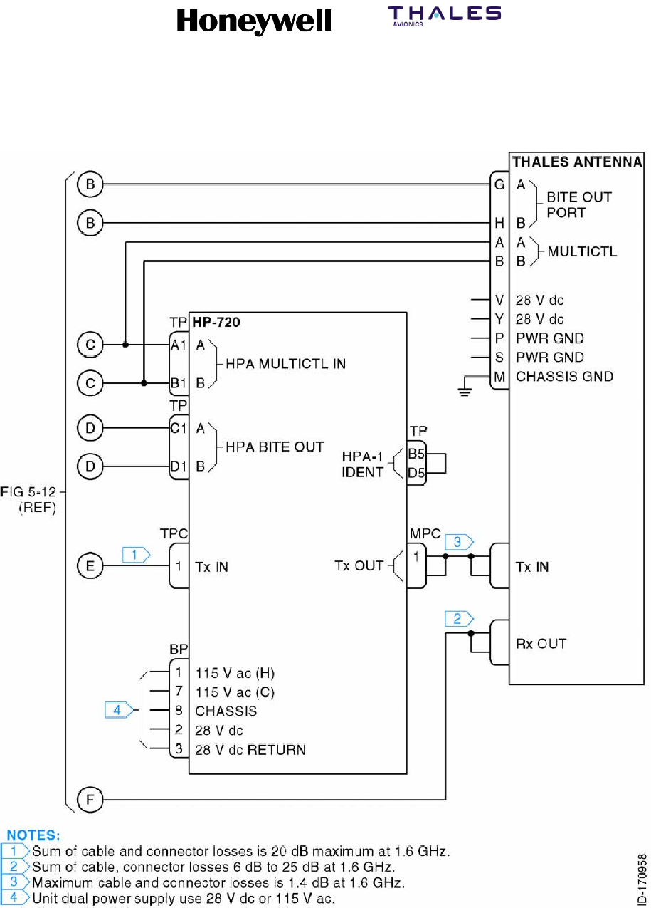
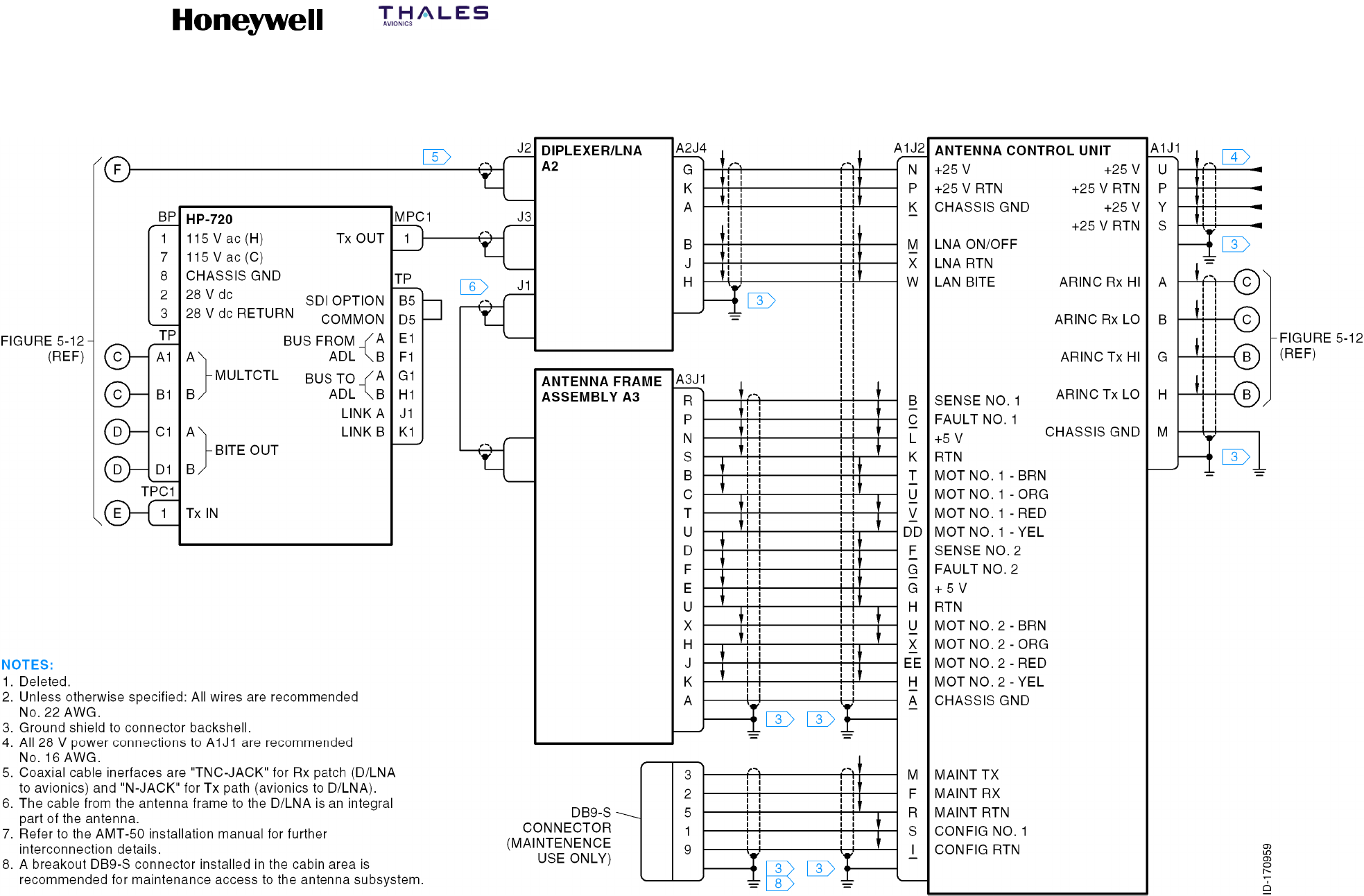
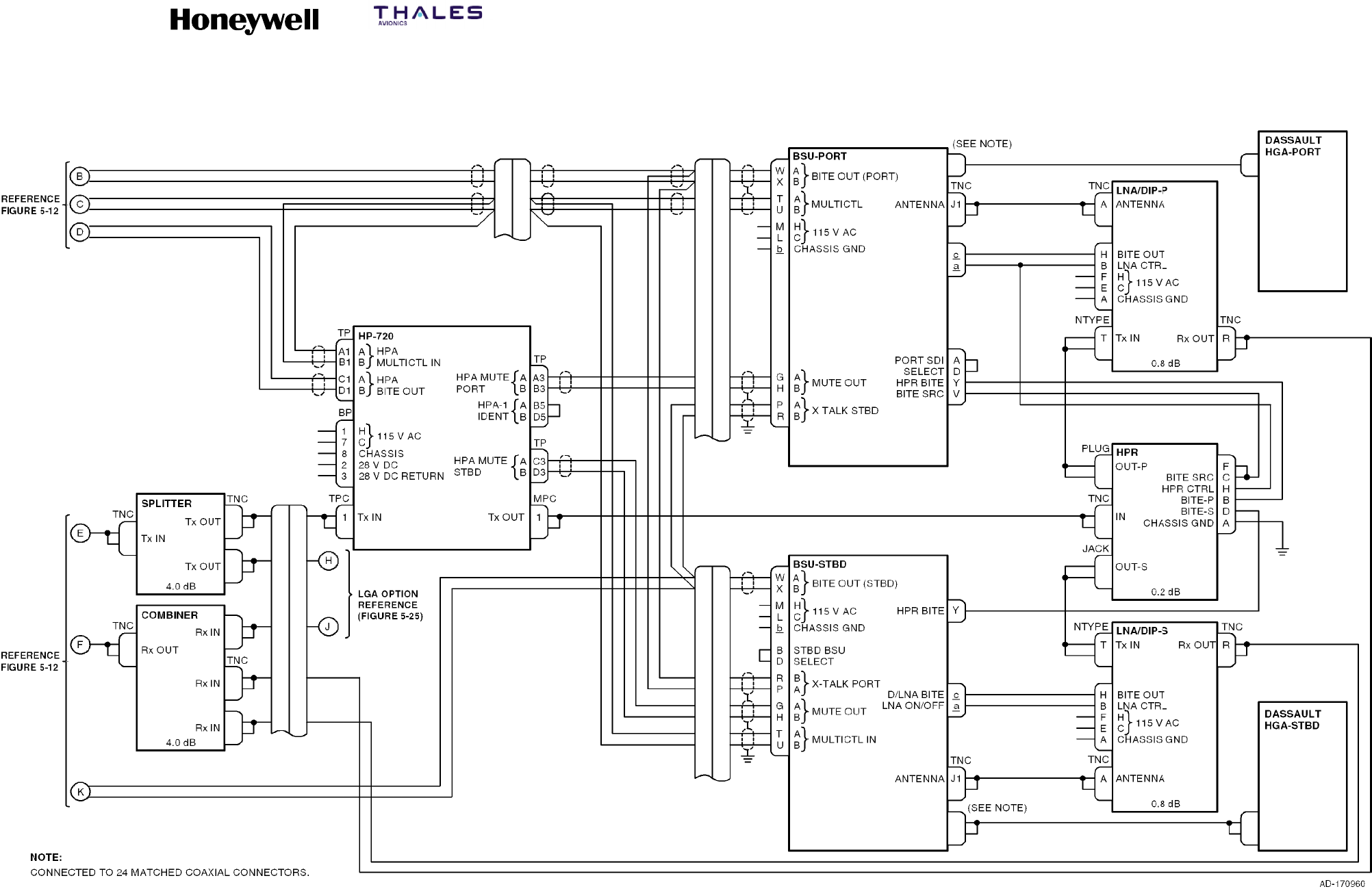
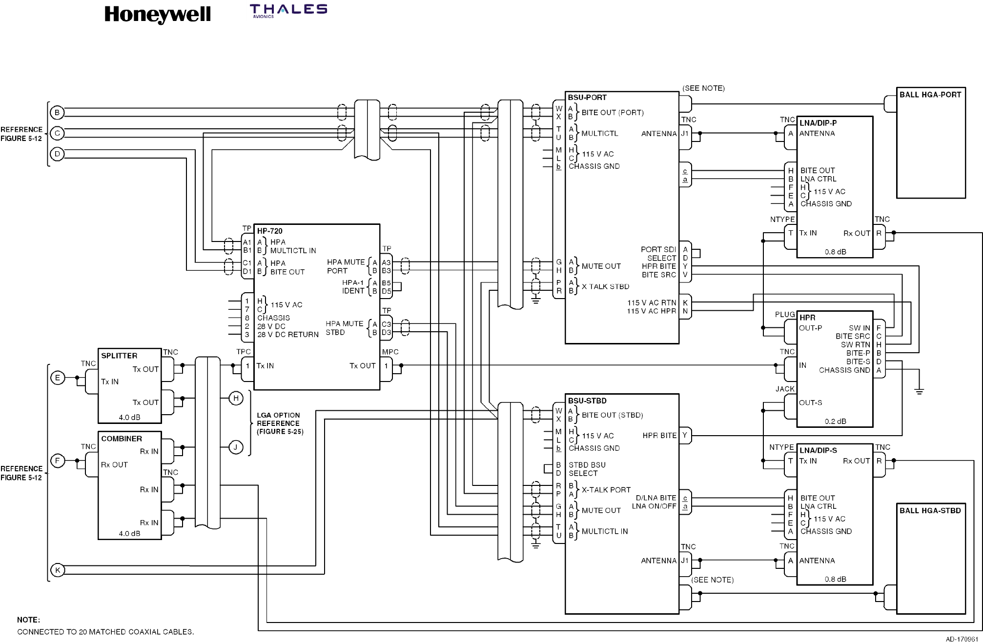
(1) The information necessary to supply the electrical interconnects is shown in
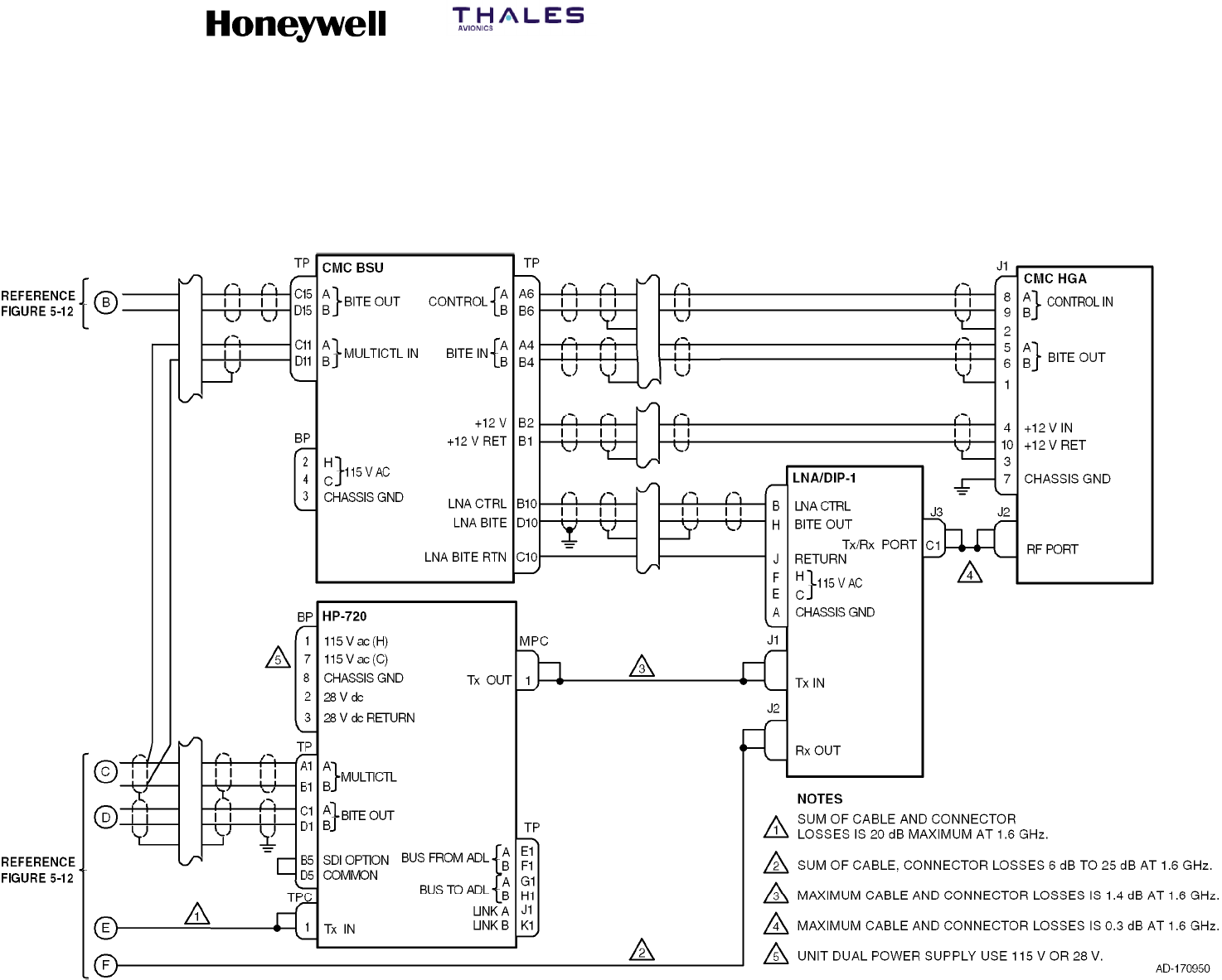
Figure 5-12 thru Figure 5-26. Interconnect diagrams are as follows:
•Figure 5-12. Satellite Data Unit & HSU Interface Diagram
•Figure 5-13. CMC Top--mounted High Gain Antenna Interface Diagram
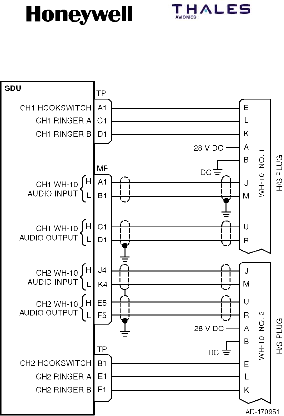
•Figure 5-14. WH--10 Handset Interface Diagram
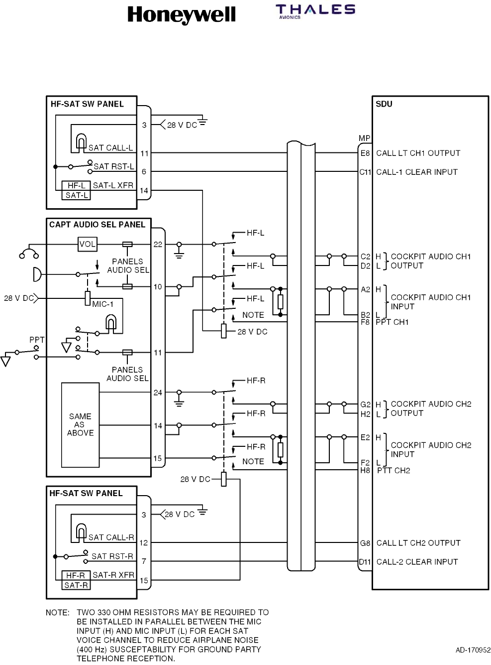
•Figure 5-15. HF--SAT Transfer Panel Interface Diagram
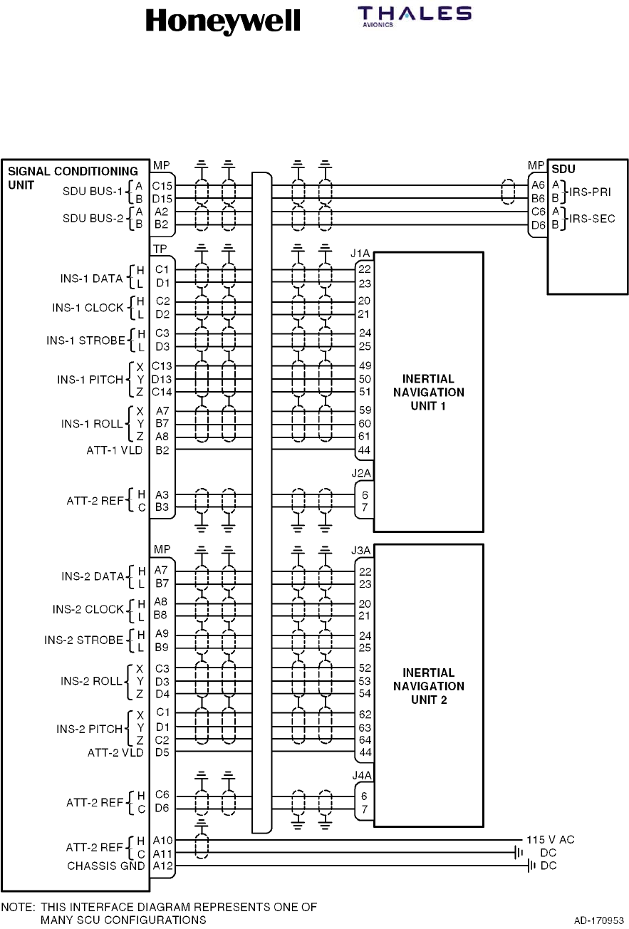
•Figure 5-16. Signal Conditioning Unit Interface Diagram
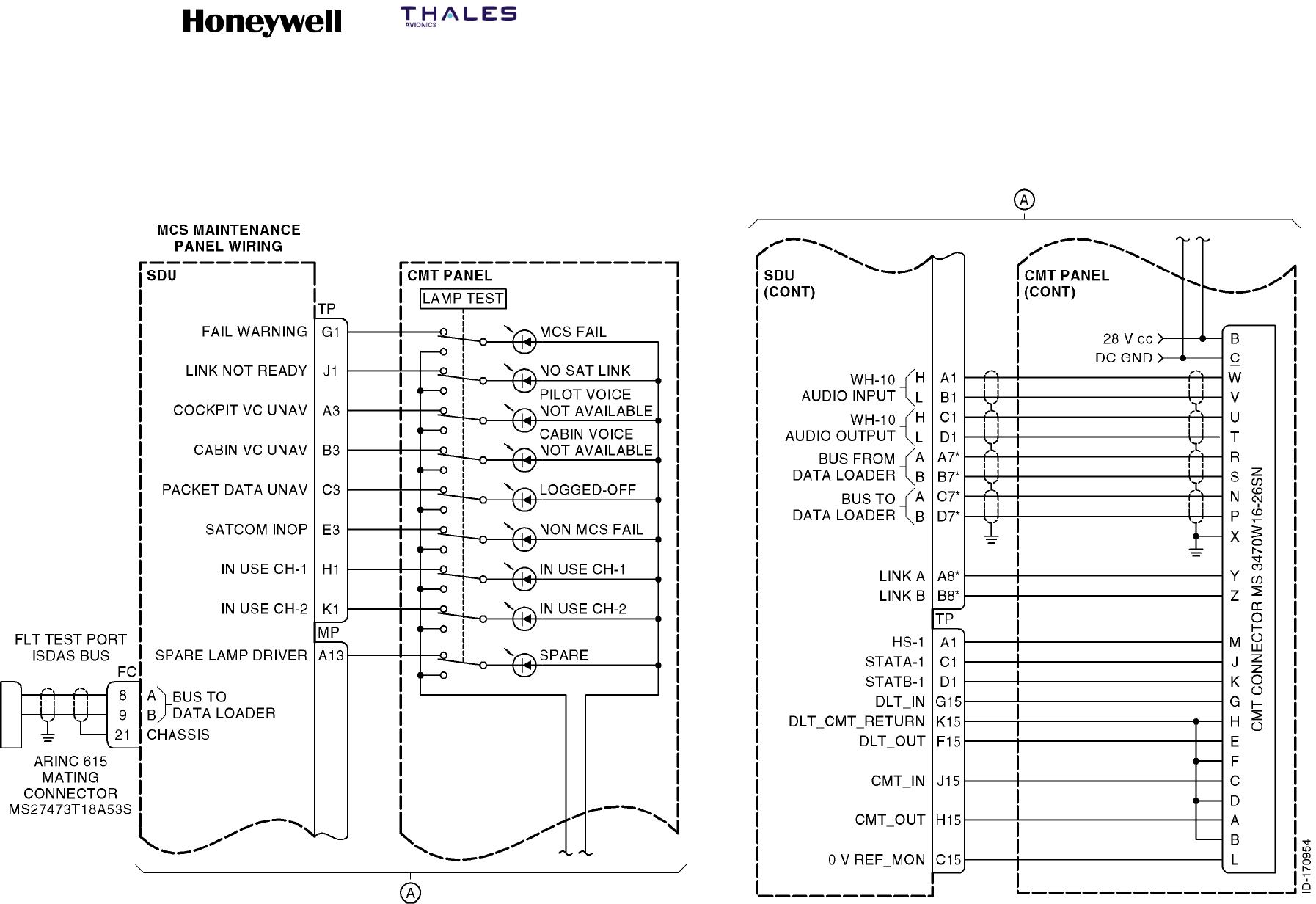
•Figure 5-17. Maintenance Panel Assembly Interface Diagram
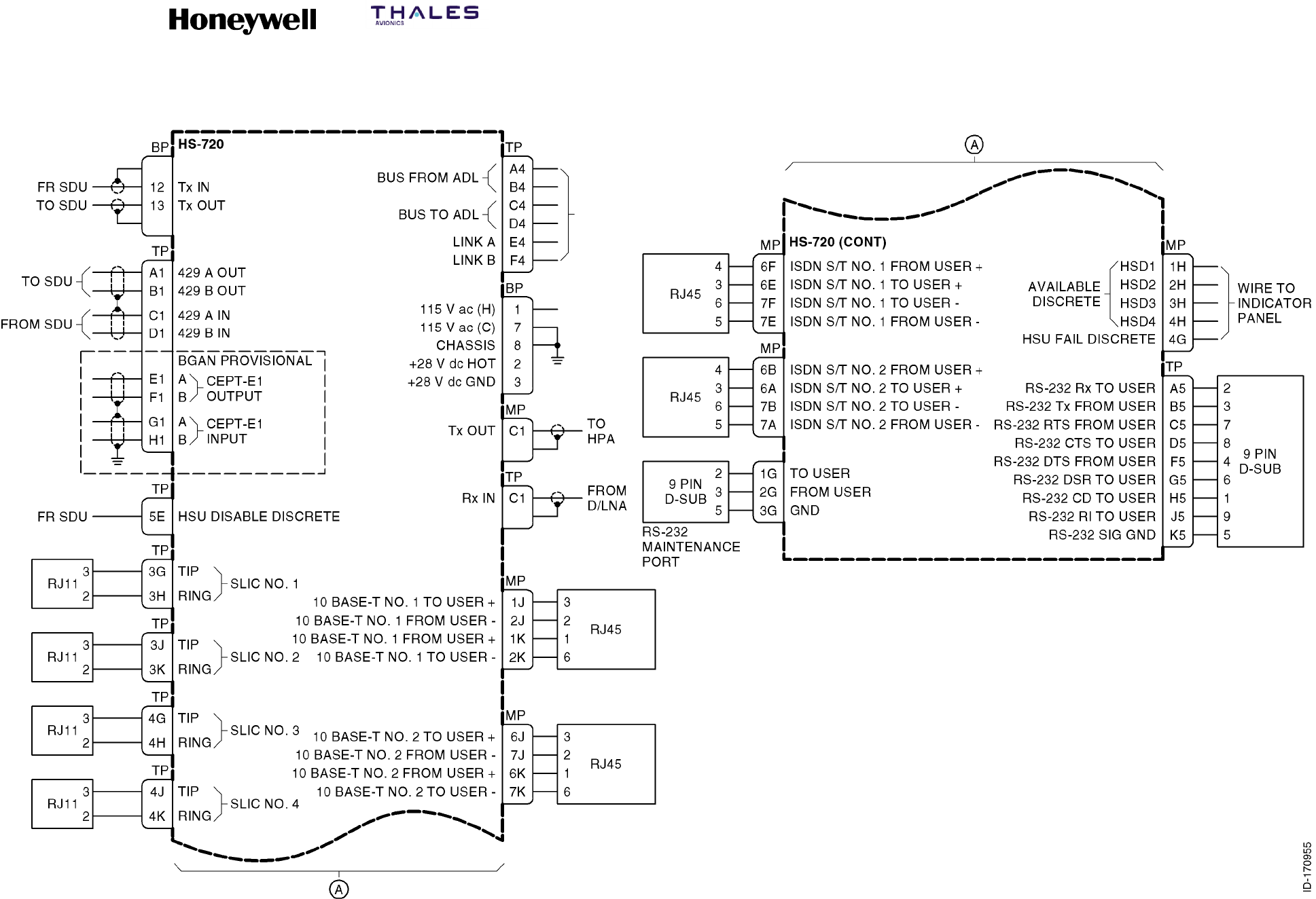
•Figure 5-18. HS--720 Interface Diagram
•Figure 5-19. HS--720 Forward ID and Configuration Pins
•Figure 5-20. Tecom Top--Mounted High Gain Antenna Interface Diagram
•Figure 5-21. Mechanically Steered High Gain Antenna Interface Diagram
•Figure 5-22. AMT--50 Mechanically Steered High Gain Antenna Interface Diagram
•Figure 5-23. Dassault Conformal High Gain Antenna Interface Diagram
•Figure 5-24. Ball Conformal High Gain Antenna Interface Diagram
•Figure 5-25. Low Gain Antenna Interface Diagram
•Figure 5-26. Toyocom Top--Mounted High Gain Antenna Interface Diagram.
(2) The applicable configuration pins in the aircraft wiring must be connected to make the
MCS system functional. The SDU receives and sends 30 system configuration
discrete inputs through the configuration pins to properly match the avionics
equipment installed on the aircraft (see Figure 5-12 and Paragraph 4. to identify the
configuration pins).
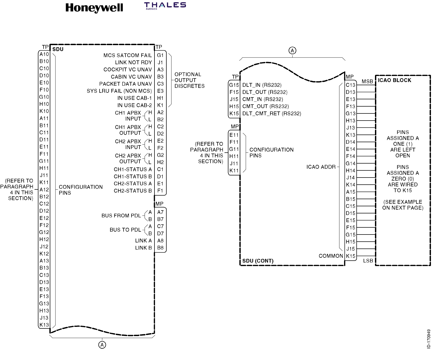
(3) The SDU receives a 24-bit ICAO address that identifies the aircraft in which the SDU
is installed (Figure 5-12). Continuity is defined as a resistance of 10 ohms or less
between a configuration pin or address pin and the common. Continuity is broken
when the resistance between a configuration pin or address pin and common
measures 100k ohms or greater.
(4) Table 5-6 lists ICAO Block Strapping.

SYSTEM DESCRIPTION, INSTALLATION, AND MAINTENANCE MANUAL
MCS--4200/7200 Multi--Channel SATCOM System
23--20--35 15 Jul 2006
Honeywell International Inc. Do not copy without express permission of Honeywell.
Page 5--22
Blank Page
SYSTEM DESCRIPTION, INSTALLATION, AND MAINTENANCE MANUAL
MCS--4200/7200 Multi--Channel SATCOM System
23--20--35 15 Jul 2006
Honeywell International Inc. Do not copy without express permission of Honeywell.
Page 5--23/5--24
Figure 5-12 (Sheet 1). Satellite Data Unit & HSU Interface Diagram
SYSTEM DESCRIPTION, INSTALLATION, AND MAINTENANCE MANUAL
MCS--4200/7200 Multi--Channel SATCOM System
23--20--35 15 Jul 2006
Honeywell International Inc. Do not copy without express permission of Honeywell.
Page 5--25/5--26
Figure 5-12 (Sheet 2). Satellite Data Unit & HSU Interface Diagram
SYSTEM DESCRIPTION, INSTALLATION, AND MAINTENANCE MANUAL
MCS--4200/7200 Multi--Channel SATCOM System
23--20--35 15 Jul 2006
Honeywell International Inc. Do not copy without express permission of Honeywell.
Page 5--27/5--28
Figure 5-12 (Sheet 3). Satellite Data Unit & HSU Interface Diagram

SYSTEM DESCRIPTION, INSTALLATION, AND MAINTENANCE MANUAL
MCS--4200/7200 Multi--Channel SATCOM System
23--20--35 15 Jul 2006
Honeywell International Inc. Do not copy without express permission of Honeywell.
Page 5--29
Table 5-6. ICAO Block Strapping
Example: AES ID 53375006 (Octal)
Octal Binary SDU Connector Pin (MP)
1C13
5 0 D13
1E13
0F13
3 1 G13
1H13
0 J13
3 1 K13
1D14
1E14
7 1 F14
1G14
1H14
5 0 J14
1K14
0A15
0 0 B15
0C15
0D15
0 0 E15
0F15
1G15
6 1 H15
0 J15
Common K15
NOTES:
1. 53375006 (Octal) = 101011011111101000000110 (Binary).
2. Binary 1 = Open; Binary 0 = Ground.
3. Pins assigned a zero (0) are wired to SDU connector pin MP--K15 (common).

SYSTEM DESCRIPTION, INSTALLATION, AND MAINTENANCE MANUAL
MCS--4200/7200 Multi--Channel SATCOM System
23--20--35 15 Jul 2006
Honeywell International Inc. Do not copy without express permission of Honeywell.
Page 5--30
Blank Page
SYSTEM DESCRIPTION, INSTALLATION, AND MAINTENANCE MANUAL
MCS--4200/7200 Multi--Channel SATCOM System
23--20--35 15 Jul 2006
Honeywell International Inc. Do not copy without express permission of Honeywell.
Page 5--31/5--32
Figure 5-13. CMC Top--mounted High Gain Antenna (HGA) Interface Diagram
SYSTEM DESCRIPTION, INSTALLATION, AND MAINTENANCE MANUAL
MCS--4200/7200 Multi--Channel SATCOM System
23--20--35 15 Jul 2006
Honeywell International Inc. Do not copy without express permission of Honeywell.
Page 5--33
Figure 5-14. WH--10 Handset Interface Diagram
SYSTEM DESCRIPTION, INSTALLATION, AND MAINTENANCE MANUAL
MCS--4200/7200 Multi--Channel SATCOM System
23--20--35 15 Jul 2006
Honeywell International Inc. Do not copy without express permission of Honeywell.
Page 5--34
Figure 5-15. HF-SAT Transfer Panel Interface Diagram
SYSTEM DESCRIPTION, INSTALLATION, AND MAINTENANCE MANUAL
MCS--4200/7200 Multi--Channel SATCOM System
23--20--35 15 Jul 2006
Honeywell International Inc. Do not copy without express permission of Honeywell.
Page 5--35
Figure 5-16. Signal Conditioning Unit Interface Diagram

SYSTEM DESCRIPTION, INSTALLATION, AND MAINTENANCE MANUAL
MCS--4200/7200 Multi--Channel SATCOM System
23--20--35 15 Jul 2006
Honeywell International Inc. Do not copy without express permission of Honeywell.
Page 5--36
Blank Page
SYSTEM DESCRIPTION, INSTALLATION, AND MAINTENANCE MANUAL
MCS--4200/7200 Multi--Channel SATCOM System
23--20--35 15 Jul 2006
Honeywell International Inc. Do not copy without express permission of Honeywell.
Page 5--37/5--38
Figure 5-17. Maintenance Panel Assembly Interface Diagram
SYSTEM DESCRIPTION, INSTALLATION, AND MAINTENANCE MANUAL
MCS--4200/7200 Multi--Channel SATCOM System
23--20--35 15 Jul 2006
Honeywell International Inc. Do not copy without express permission of Honeywell.
Page 5--39/5--40
Figure 5-18. HS--720 Interface Diagram
SYSTEM DESCRIPTION, INSTALLATION, AND MAINTENANCE MANUAL
MCS-4200/7200
TEMPORARY REVISION NO. 23-1
23-20-35 Page 40 of 53
28 Sep 2009
© Honeywell International Inc. Do not copy without express permission of Honeywell.
INSERT PAGE 40 OF 53 FACING PAGE 5-41/5-42.
Reason: To add Note 3 to incorporate SBB operation data to Figure 5-19.
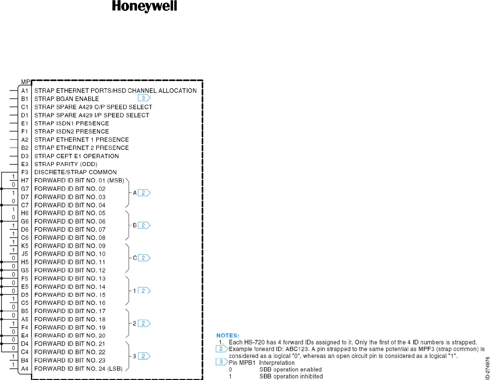
Replace Figure 5-19 with the new illustration as follows:
Figure 5-19. HS-720 Forward ID & Configuration Pins
SYSTEM DESCRIPTION, INSTALLATION, AND MAINTENANCE MANUAL
MCS--4200/7200 Multi--Channel SATCOM System
23--20--35 15 Jul 2006
Honeywell International Inc. Do not copy without express permission of Honeywell.
Page 5--41/5--42
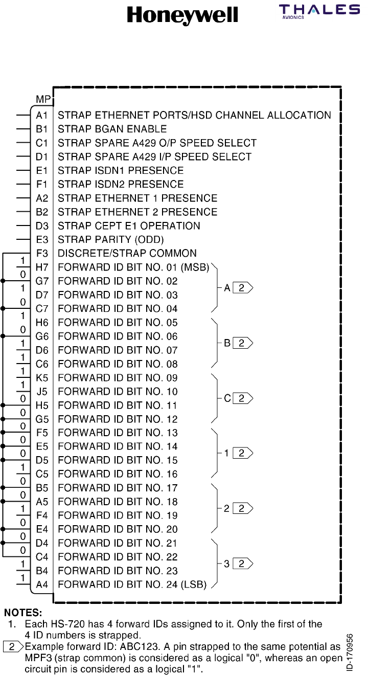
Figure 5-19. HS--720 Forward ID & Configuration Pins
SYSTEM DESCRIPTION, INSTALLATION, AND MAINTENANCE MANUAL
MCS--4200/7200 Multi--Channel SATCOM System
23--20--35 15 Jul 2006
Honeywell International Inc. Do not copy without express permission of Honeywell.
Page 5--43/5--44
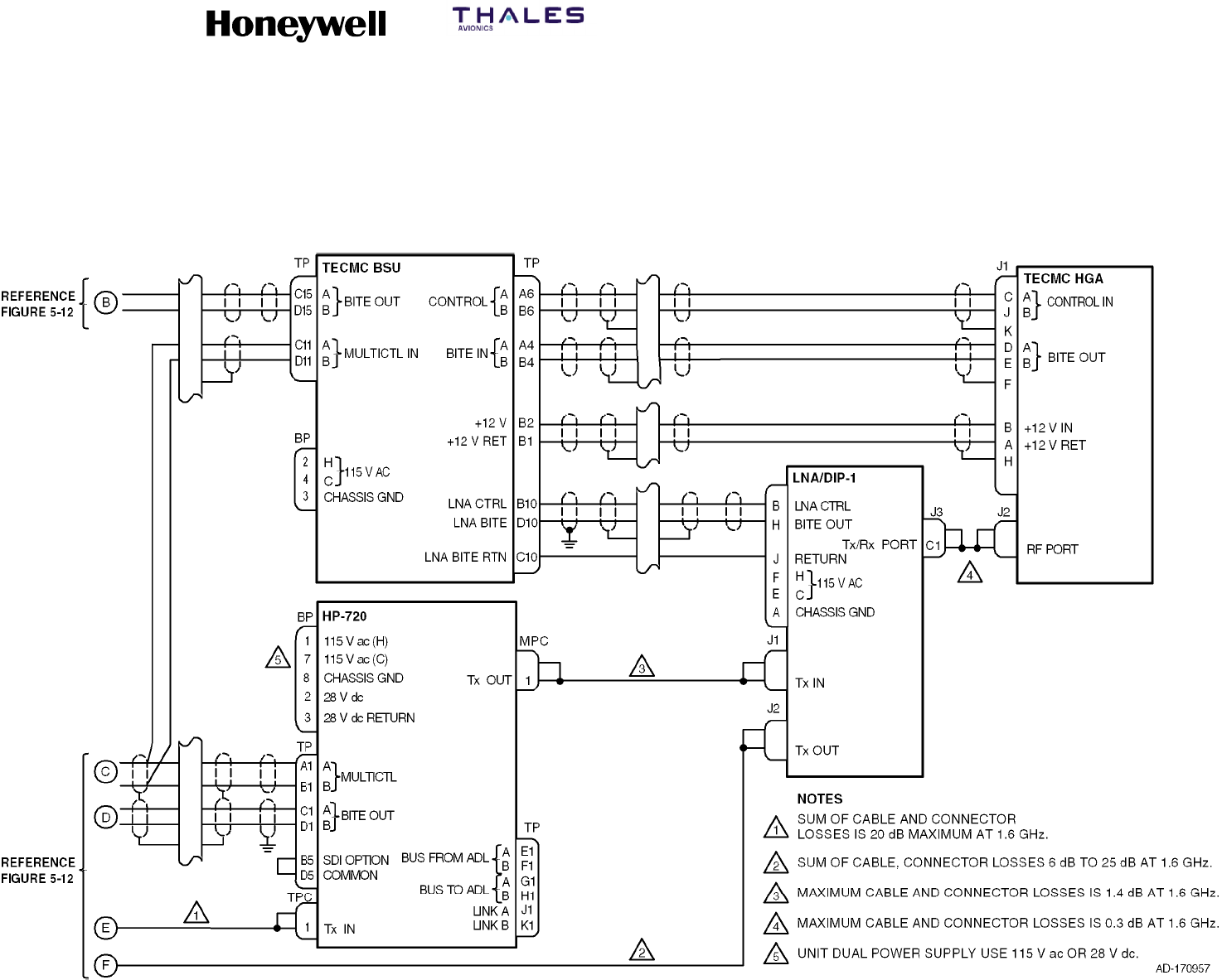
Figure 5-20. Tecom Top--Mount High Gain Antenna Interface Diagram
SYSTEM DESCRIPTION, INSTALLATION, AND MAINTENANCE MANUAL
MCS--4200/7200 Multi--Channel SATCOM System
23--20--35 15 Jul 2006
Honeywell International Inc. Do not copy without express permission of Honeywell.
Page 5--45/5--46
Figure 5-21. Thales Mechanically Steered High Gain Antenna Interface Diagram
SYSTEM DESCRIPTION, INSTALLATION, AND MAINTENANCE MANUAL
MCS--4200/7200 Multi--Channel SATCOM System
23--20--35 15 Jul 2006
Honeywell International Inc. Do not copy without express permission of Honeywell.
Page 5--47/5--48
Figure 5-22. EMS AMT--50 Mechanically Steered High Gain Antenna Interface Diagram
SYSTEM DESCRIPTION, INSTALLATION, AND MAINTENANCE MANUAL
MCS--4200/7200 Multi--Channel SATCOM System
23--20--35 15 Jul 2006
Honeywell International Inc. Do not copy without express permission of Honeywell.
Page 5--49/5--50
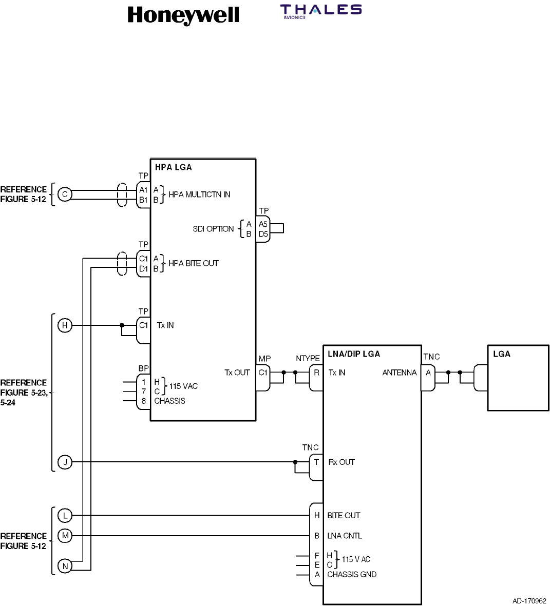
Figure 5-23. Dassault Conformal High Gain Antenna Interface Diagram
SYSTEM DESCRIPTION, INSTALLATION, AND MAINTENANCE MANUAL
MCS--4200/7200 Multi--Channel SATCOM System
23--20--35 15 Jul 2006
Honeywell International Inc. Do not copy without express permission of Honeywell.
Page 5--51/5--52
Figure 5-24. Ball Conformal High Gain Antenna Interface Diagram
SYSTEM DESCRIPTION, INSTALLATION, AND MAINTENANCE MANUAL
MCS--4200/7200 Multi--Channel SATCOM System
23--20--35 15 Jul 2006
Honeywell International Inc. Do not copy without express permission of Honeywell.
Page 5--53/5--54
Figure 5-25. Low Gain Antenna Interface Diagram
SYSTEM DESCRIPTION, INSTALLATION, AND MAINTENANCE MANUAL
MCS--4200/7200 Multi--Channel SATCOM System
23--20--35 15 Jul 2006
Honeywell International Inc. Do not copy without express permission of Honeywell.
Page 5--55/5--56
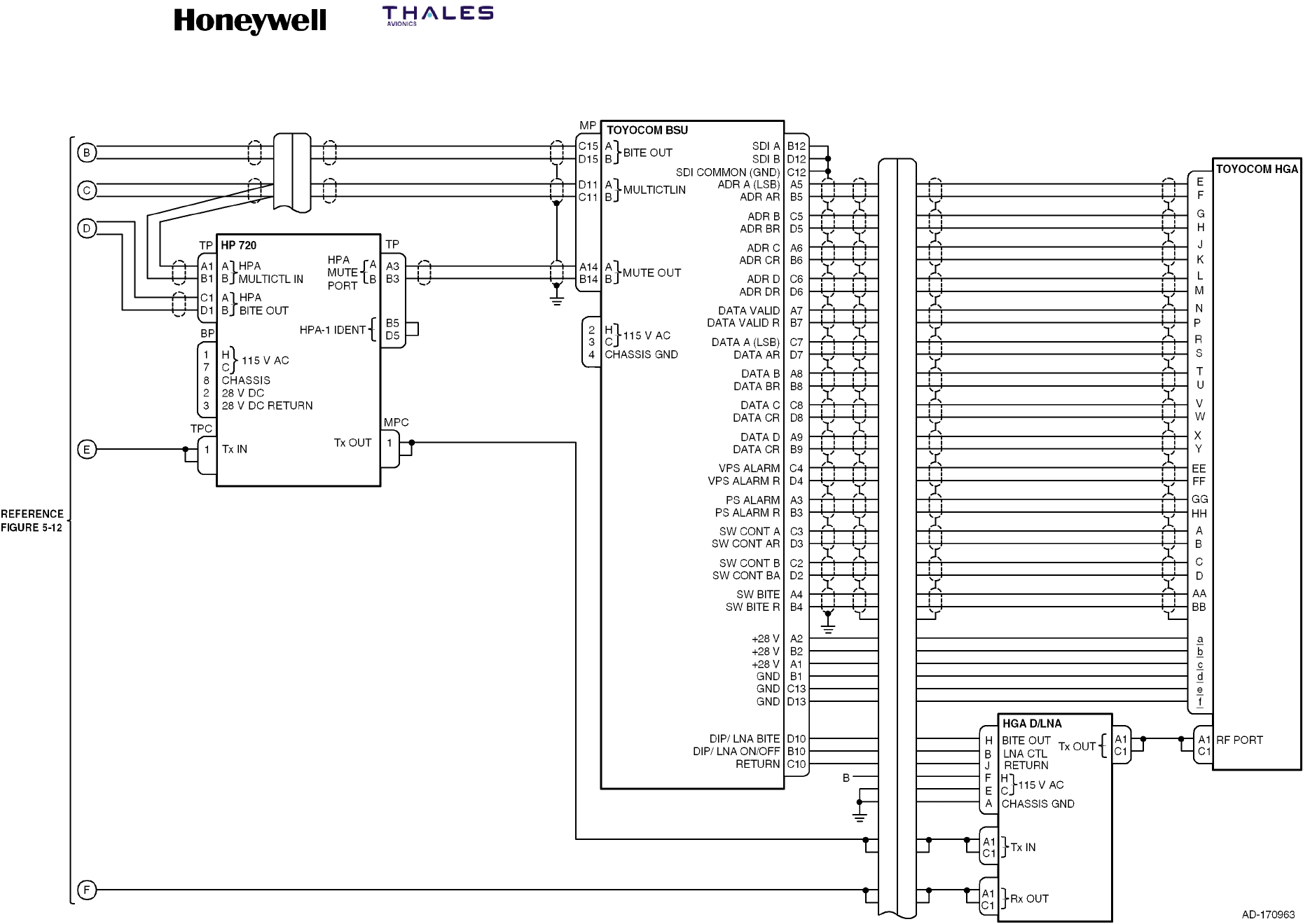
Figure 5-26. Toyocom Top--mounted High Gain Antenna Interface Diagram

SYSTEM DESCRIPTION, INSTALLATION, AND MAINTENANCE MANUAL
MCS-4200/7200
TEMPORARY REVISION NO. 23-1
23-20-35 Page 41 of 53
28 Sep 2009
© Honeywell International Inc. Do not copy without express permission of Honeywell.
INSERT PAGE 41 OF 53 FACING PAGE 5-57.
Reason: To change Table 5-7 to incorporate the GNSS frequency check algorithm data for pins TP11E
thru TP11K.
Replace Table 5-7 as follows:
Table 5-7. Configuration Pins
Pin Definition
TP11E HPA ANTENNA SUBSYSTEM CONFIGURATION AND GNSS FREQUENCY CHECK ALGORITHM
TP11F HPA ANTENNA SUBSYSTEM CONFIGURATION AND GNSS FREQUENCY CHECK ALGORITHM
TP11G HPA ANTENNA SUBSYSTEM CONFIGURATION AND GNSS FREQUENCY CHECK ALGORITHM
TP11H HPA ANTENNA SUBSYSTEM CONFIGURATION AND GNSS FREQUENCY CHECK ALGORITHM
TP11J HPA ANTENNA SUBSYSTEM CONFIGURATION AND GNSS FREQUENCY CHECK ALGORITHM
TP11K HPA ANTENNA SUBSYSTEM CONFIGURATION AND GNSS FREQUENCY CHECK ALGORITHM

SYSTEM DESCRIPTION, INSTALLATION, AND MAINTENANCE MANUAL
MCS--4200/7200 Multi--Channel SATCOM System
23--20--35 15 Jul 2006
Honeywell International Inc. Do not copy without express permission of Honeywell.
Page 5--57
4. Configuration Pins
A. General
(1) The following paragraphs supply system configuration pin definitions and
interpretation information. Pins assigned to take on the binary one stateinagiven
code should be left as an open circuit. Pins assigned to take on the binary zero state
in the code should be wired to SDU connector pin MP15K (address common) on the
airframe side of the connection. The configuration pins are listed in Table 5-7.
Table 5-7. Configuration Pins
Pin Definition
TP10A AVAILABILITY OF ARINC 429 ICAO 24--BIT AIRCRAFT ADDRESS (AES ID) FROM 429
PORTS
TP10B FMC CONNECTION TO SDU
TP10C FMC CONNECTION TO SDU
TP10D ARINC 429 BUS SPEED TO/FROM CMU NO. 1 AND CMU NO. 2
TP10E CPDF CONFIGURATION
TP10F 429 BUS SPEED OF AES ID INPUT
TP10G HSU INSTALLED
TP10H SCDU CONTROLLER TYPE
TP10J RESERVED FOR STRAP OPTION
TP10K CALL LIGHT ACTIVATION
TP11A STRAP PARITY (ODD: COVERING THE OTHER 39 STRAP PINS)
TP11B CCS PRESENCE
TP11C IRS CONFIGURATION
TP11D IRS CONFIGURATION
TP11E HPR/HPA/BSU/LGA CONFIGURATION
TP11F HPR/HPA/BSU/LGA CONFIGURATION
TP11G HPR/HPA/BSU/LGA CONFIGURATION
TP11H HPR/HPA/BSU/LGA CONFIGURATION
TP11J HPR/HPA/BSU/LGA CONFIGURATION
TP11K HPR/HPA/BSU/LGA CONFIGURATION
TP12A CFDS TYPE
TP12B CFDS TYPE
TP12C CFDS TYPE

SYSTEM DESCRIPTION, INSTALLATION, AND MAINTENANCE MANUAL
MCS--4200/7200 Multi--Channel SATCOM System
23--20--35 15 Jul 2006
Honeywell International Inc. Do not copy without express permission of Honeywell.
Page 5--58
Table 5-7. Configuration Pins (cont)
Pin Definition
TP12D PAD FOR CFDS/SDU CONFIGURATION
TP12E SDU CONFIGURATION
TP12F SDU NUMBER
TP12G CMU NO. 1 CONFIGURATION
TP12H CMU NO. 2 CONFIGURATION
TP12J MCDU/WSC NO. 1 CONFIGURATION
TP12K MCDU/WSC NO. 2 CONFIGURATION
TP13A PRIORITY 4 CALLS TO/FROM COCKPIT
TP13B ARINC 429 BUS SPEED TO MCDU NO. 1, NO. 2, AND NO. 3
TP13C COCKPIT VOICE CALL LIGHT/CHIME OPTIONS
TP13D COCKPIT VOICE CALL LIGHT/CHIME OPTIONS
TP13E MCDU/WSC NO. 3 CONFIGURATION
TP13F SDU CODEC 1 WIRING
TP13G SDU CODEC 1 WIRING
TP13H SDU CODEC 2 WIRING
TP13J SDU CODEC 2 WIRING
TP13K COCKPIT HOOKSWITCH SIGNALING METHOD
MP11E CM--250 CGU CONNECTION CONFIGURATION
MP11F COCKPIT CALL DISCRETE SIGNALING MODE
MP11G SPARE
MP11H SPARE
MP11J SPARE
MP11K PARITY
B. Availability of ARINC 429 ICAO ADDRESS (AES ID) from 429 Ports
(1) The interpretation of this configuration pin is given in Table 5-8.

SYSTEM DESCRIPTION, INSTALLATION, AND MAINTENANCE MANUAL
MCS--4200/7200 Multi--Channel SATCOM System
23--20--35 15 Jul 2006
Honeywell International Inc. Do not copy without express permission of Honeywell.
Page 5--59
Table 5-8. Availability of ARINC 429 ICAO ADDRESS (AES ID) from 429 Ports
TP10 Pin A Interpretation
1ICAO ADDRESS (AES ID) NOT AVAILABLE FROM CMU NO. 1 OR CMU NO. 2 OR
AES ID INPUT
0ICAO ADDRESS (AES ID) IS AVAILABLE FROM CMU NO. 1 OR CMU NO. 2 OR AES
ID INPUT
(2) When wired to the zero state, the TP10A configuration pin indicates the ICAO 24--bit
aircraft address (AES ID) is available in the ARINC 429 label 275/276 format from
one or both of the SDU CMU input ports or ARINC 429 label 214/216 format from the
AES ID input port, and that one of those ARINC 429 sources of the address is used
with no specific preference for CMU 1, CMU 2, or the AES ID input. In this state, the
discrete inputs on SDU pins MP13C thru MP13K and MP14D thru MP14J are not
assumed to be wired and the SDU does not use the discretes, even if the ARINC 429
sources fail or remain inactive.
(3) In the zero state, the SDU monitors the CMU 1, CMU 2, and AES ID input buses until
a valid ICAO address is received. Bits 1 thru 16 of the AES ID are obtained from the
label 214/275 word and bits 17 thru 24 are obtained from the label 216/276 word.
The SDU only constructs a full 24-bit address from labels 214/275 and 216/276
words received from the same input port (e.g., label 214/275 from CMU 1 can not be
combined with label 216/276 from CMU 2 or label 216 from the AES ID input). The
address is only considered valid if it does not consist of all zeros or ones, and has
been received in ARINC 429 words with their sign--status matrix (SSM) indicating
normal operation.
(4) If address words containing either all zeros or ones are received, followed by address
words with a valid address (i.e., not all zeros or ones), the SDU verifies the receipt of
both labels 214/275 and 216/276 at least twice with the same address bits content in
each respective word before declaring the address valid. This is to preclude the SDU
from inadvertently and prematurely assuming the address is valid after only one of
the two labels has yielded a valid segment of the overall address, but the most
previously received copy of the other label has not yet been updated to its intended
code. The root problem is that the 24 correlated address bits are transmitted in two
separate asynchronous words that are not inherently correlated/paired. This
requirement is intended to effectively pair the label 214/275 and 216/276
transmissions.
SYSTEM DESCRIPTION, INSTALLATION, AND MAINTENANCE MANUAL
MCS--4200/7200 Multi--Channel SATCOM System
23--20--35 15 Jul 2006
Honeywell International Inc. Do not copy without express permission of Honeywell.
Page 5--60
(5) Once a valid ICAO address is received on any bus, the SDU ignores further data
received on any of the buses until the next POST/PAST. This requirement relieves
the SDU of having to deal with the possibility that the ICAO technical address might
change while the SDU is logged-on. The AES ID (ICAO address) is determined at
startup and cannot change until the next POST/PAST. The SDU does not log-on until
it has a valid AES ID. The SDU waits indefinitely to receive a valid address from an
available ARINC 429 source rather than giving up at the end of POST/PAST, since it
cannot proceed as an AES without the address. If the configuration pin indicates the
ARINC 429 source is available, the discretes are not wired. The SDU will not revert to
the discretes at the end of POST/PAST as the CMU may not yet be operational.
(6) If configuration pin TP10A is wired to the one state, then neither CMU input port nor
the AES ID input port is capable of supplying the AES ID in the ARINC 429 format
and the SDU reads the AES ID from the discrete inputs.
(7) With either the ARINC 429 or discrete inputs source, an AES ID of all zeros or all
ones (binary) is invalid (typically indicative of an unprogrammed address) which
constitutes a failure. The SDU does not attempt to log-on to a GES with an invalid
AES ID.
C. FMC Connection to SDU
(1) The interpretation of this configuration pin is given in Table 5-9.
Table 5-9. FMC Connection to SDU
TP10 Pins
B C Interpretation
0 0 FMC NO. 1 CONNECTED, FMC NO. 2 CONNECTED
0 1 FMC NO. 1 CONNECTED, FMC NO. 2 NOT CONNECTED
1 0 FMC NO. 1 NOT CONNECTED, FMC NO. 2 CONNECTED
1 1 NEITHER FMC CONNECTED
NOTE: SATCOM does not support the FMC interface.
D. ARINC 429 Speed to/from CMU No. 1 and CMU No. 2
(1) The interpretation of this configuration pin is given in Table 5-10.
Table 5-10. ARINC 429 Speed to/from CMU No. 1 and CMU No. 2
TP10 Pin D Interpretation
1LOW SPEED ARINC 429 DATA BUS
0HIGH SPEED ARINC 429 DATA BUS
SYSTEM DESCRIPTION, INSTALLATION, AND MAINTENANCE MANUAL
MCS--4200/7200 Multi--Channel SATCOM System
23--20--35 15 Jul 2006
Honeywell International Inc. Do not copy without express permission of Honeywell.
Page 5--61
(2) When this configuration pin is wired to the zero state, the SDU operates its input and
output ARINC 429 buses for the CMUs No. 1 and No. 2 at high speed. When wired to
the one state, the SDU operates these buses at the low speed.
E. Cabin Packet Data Function (CPDF)
(1) The interpretation of this configuration pin is given in Table 5-11.
Table 5-11. Cabin Packet Data Function (CPDF)
TP10 Pin E Interpretation
0CPDF CONNECTED
1CPDF NOT CONNECTED
(2) When wired to the zero state, this configuration pin indicates the input designated for
the CPDF (MP1E and MP1F) is connected to an ARINC 429 source of data--3 packet
data and that the SDU output (pins MP9A and MP9B) is wired to the CPDF. The SDU
only logs/reports/ indicates CPDF failures and bus inactivity on the CPDF input bus if
this configuration pin indicates the bus is supposed to be connected to an ARINC
source. The SDU can assume (for functional purposes) the presence of the CPDF
connections from the state of this pin.
F. ARINC 429 BUS Speed of AES ID Input
(1) The interpretation of this configuration pin is given in Table 5-12.
Table 5-12. ARINC 429 Bus Speed of AES ID Input
TP10 Pin F Interpretation
0HIGH SPEED ARINC 429 BUS
1LOW SPEED ARINC 429 BUS
G. HSU Presence
(1) The interpretation of this configuration pin is given in Table 5-13.
Table 5-13. HSU Presence
TP10 Pin G Interpretation
0HSU INSTALLED
1HSU NOT INSTALLED
(2) When wired to the zero state, this configuration indicates that SDU pins MP9E/F and
MP9G/H are connected to the high speed data unit (HSDU). The SDU only
logs/reports/indicates inactivity on its HSU input bus when this strap is in the zero
state. The SDU assumes, for functional purposes, the presence of the HSU from the
state of this strap.
SYSTEM DESCRIPTION, INSTALLATION, AND MAINTENANCE MANUAL
MCS--4200/7200 Multi--Channel SATCOM System
23--20--35 15 Jul 2006
Honeywell International Inc. Do not copy without express permission of Honeywell.
Page 5--62
H. SDU Controller Type
(1) The interpretation of this configuration pin is given in Table 5-14.
Table 5-14. SDU Controller Type
TP10 Pin H Interpretation
0WSC SDU CONTROLLER TYPE
1MCDU/SDU CONTROLLER TYPE
(2) When wired to the zero state, the SDU interfaces to the Williamsburg SDU controller
(WSC) interface. When wired to the one state, the SDU interfaces to the
Multi--Controller Display Unit (MCDU). The SDU chooses the appropriate interface
protocols and BITE failures based on the state of TP10H.
(3) When the WSC SDU controller type is selected, TP13B (Table 5--29) must also be
wired to the zero state since the WSC interface only operates at low speed.
I. Call Light On (Air/Ground Calls)
(1) The interpretation of this configuration pin is given in Table 5-15.
Table 5-15. Call Light On (Air/Ground Calls)
TP10 Pin K Interpretation
0CALL LIGHT ON AT CALL INITIATION (FOR AIR/GROUND CALLS)
1CALL LIGHT ON AT CALL CONNECTION (FOR AIR/GROUND CALLS)
J. Strap Parity (ODD)
(1) The interpretation of this configuration pin is given in Table 5-16.
Table 5-16. Strap Parity (ODD)
TP11 Pin A Interpretation
0SUM OF ALL OTHER STRAPS SET TO 1 IS ODD
1SUM OF ALL OTHER STRAPS SET TO 1 IS EVEN
(2) The coverage of the parity pin is SDU connector pins TP10A thru TP10K and TP11B
thru TP13K (39 pins other than itself). The parity pin is programmed to a zero or one
to yield an odd number of strap bits set to the one state, including the parity pin itself.
(3) The parity pin is wired to yield odd parity over all 40 configuration pins (i.e., the parity
pin is programmed to the zero or one state to yield an odd number of configuration
pins wired to the one state, including itself. The SDU verifies the state of the parity
pin is correct when the configuration pins are read (typically once per power cycle just
after power-up). An invalid state of the parity pin is logged/reported/indicated; the
states of the other configuration pins are used as read despite the parity error.
SYSTEM DESCRIPTION, INSTALLATION, AND MAINTENANCE MANUAL
MCS--4200/7200 Multi--Channel SATCOM System
23--20--35 15 Jul 2006
Honeywell International Inc. Do not copy without express permission of Honeywell.
Page 5--63
K. Cabin Communications System (CCS)
(1) The interpretation of this configuration pin is given in Table 5-17.
Table 5-17. Cabin Communications System (CCS)
TP11 Pin B Interpretation
0CCS INSTALLED
1CCS NOT INSTALLED
(2) When wired to the zero state, this configuration indicates that SDU pins MP2J/K and
MP3A/B (CEPT--E1 input and output respectively) are connected to the CCS CTU.
(3) The SDU only logs, reports, and/or indicates inactivity on its CCS input bus when this
strap is in the zero state. The SDU assumes, for functional purposes, the presence of
the CCS from the state of this strap.
L. Inertial Reference System (IRS)
(1) The interpretation of these configuration pins is given in Table 5-18.
Table 5-18. Inertial Reference System (IRS)
TP11 Pins
C D Interpretation
0 0 PRIMARY IRS INSTALLED, SECONDARY IRS INSTALLED
0 1 PRIMARY IRS INSTALLED, SECONDARY IRS NOT INSTALLED
1 0 PRIMARY IRS NOT INSTALLED, SECONDARY IRS INSTALLED
1 1 PRIMARY IRS NOT INSTALLED, SECONDARY IRS NOT INSTALLED
(2) When individually wired to the zero state, configuration pins TP11C and TP11D
indicate, respectively, that the inputs designated for the primary and secondary IRSs
(MP6A/MP6B and MP6C/MP6D, respectively) are connected to an ARINC 429
source of IRS label 310, 311, 312, 314, 324, 325, and 361 information (although label
361, Inertial Altitude, is not required for SATCOM). The actual IRS (i.e., IRS No. 1,
IRS No. 2, or IRS No. 3) driving either SDU input is determined from the source
destination identifier (SDI) bits of the received ARINC words. The SDU only
logs/reports/indicates bus inactivity on either bus if the respective configuration pin
indicates that the bus is supposed to be connected to an ARINC 429 source. The
SDU can assume (for functional purposes) the presence of the IRS connections from
the state of these pins.
SYSTEM DESCRIPTION, INSTALLATION, AND MAINTENANCE MANUAL
MCS--4200/7200 Multi--Channel SATCOM System
23--20--35 15 Jul 2006
Honeywell International Inc. Do not copy without express permission of Honeywell.
Page 5--64
M. HPA/Antenna Subsystem Configuration
(1) The interpretation of these configuration pins is given in Table 5-19.
Table 5-19. HPA/Antenna Subsystem Configuration
TP11 Pins
L
G
A
+
L
N
A
T
O
P
/
P
O
R
S
T
A
R
B
O
A
R
D
R
E
S
E
R
V
E
D
F
R
E
S
E
R
V
E
E F G H J K
A
/
D
I
P
L
E
X
E
R
L
G
A
H
P
A
R
T
B
S
U
+
H
G
A
D
B
S
U
+
H
G
A
H
G
A
H
P
A
H
P
R
F
O
R
F
U
T
U
R
E
E
D
F
O
R
M
F
R
1111114 4
011111 4 4
1011114 4 4 4
0011114 44444
110111 4
010111 4
1001114 4 4 4 Note 1
0001114 4 4 4 4 Note 1
111011 4444
0
1
1
0
1
0
0
1
1
0
1
0
to 4Note 2
1
0
1
0
1
0
0
0
0
0
0
0
to 4Note 2
NOTES:
1. Not defined at this time.
2. Other configurations are possible and can be added at a later date.

SYSTEM DESCRIPTION, INSTALLATION, AND MAINTENANCE MANUAL
MCS-4200/7200
TEMPORARY REVISION NO. 23-1
23-20-35 Page 42 of 53
28 Sep 2009
© Honeywell International Inc. Do not copy without express permission of Honeywell.
INSERT PAGE 42 OF 53 FACING PAGE 5-64.
Reason: To change Table 5-19 to incorporate the GNSS frequency check algorithm data.
Replace Table 5-19 as follows:
Table 5-19. (TP11E – K) HPA/Antenna Subsystem Configuration and
GNSS Frequency Check Algorithm1
[10]
Decimal
Code Pins TP11 LGA
LGA
HPA
TOP/PORT
BSU +
HGA
STARBOARD
BSU + HGA
HGA
HPA HPR
GNSS
FREQ
CHK
REQD
GNSS
FREQ
CHK
NOT
REQD
ARINC
781
HGA
RESERVED
FOR
FUTURE
RESERVED
FOR MFR NOTES
E F G H J K
63 1 1 1 1 1 1 * * *
62 0 1 1 1 1 1 * * *
61 1 0 1 1 1 1 * * * * *
60 0 0 1 1 1 1 * * * * * * *
59 1 1 0 1 1 1 * *
58 0 1 0 1 1 1 * *
57 1 0 0 1 1 1 * *
56 0 0 0 1 1 1 * *
55 1 1 1 0 1 1 * * * * *
54 0 1 1 0 1 1 * * *
48-53 1
0
0
0
1
0
0
0
1
1
1
1
to *
47 1 1 1 1 0 1 * * *
46 0 1 1 1 0 1 * * *
45 1 0 1 1 0 1 * * * * *
44 0 0 1 1 0 1 * * * * * * *
43 1 1 0 1 0 1 * *
42 0 1 0 1 0 1 * *
41 1 0 0 1 0 1 * *
40 0 0 0 1 0 1 * *
39 1 1 1 0 0 1 * * * * *
38 0 1 1 0 0 1 * * *
8-37 1
0
0
0
1
0
0
1
0
0
1
0
to *
0-7 1
0
1
0
1
0
0
0
0
0
0
0
to *
Note 1: Other configurations are possible and may be added at a later date. Note that ARINC Characteristic 761 Attachment 1-4B Table 1-3K (which is an extension of ARINC
Characteristic 741 Table 1-4K) defines configurations which include intermediate-gain antennas (IGAs). Those IGA configurations may also apply to ARINC Characteristic
741-compatible equipment; therefore, the IGA codes defined in ARINC Characteristic 761 should be considered as reserved for those definitions in this table as well. Any
changes to this table should be coordinated with ARINC Characteristic 761. Note that the configuration codes for “GNSS Frequency Check Required” and “GNSS
Frequency Check Not Required” are identical except for TP11J. Refer to ARINC 741 Part 2 Section 3.5.4.1.1 regarding the frequency check for GNSS interference
prevention.
SYSTEM DESCRIPTION, INSTALLATION, AND MAINTENANCE MANUAL
MCS--4200/7200 Multi--Channel SATCOM System
23--20--35 15 Jul 2006
Honeywell International Inc. Do not copy without express permission of Honeywell.
Page 5--65
(2) For functional purposes, the SDU assumes the HPA and antenna subsystem
configuration of its particular installation from states of these configuration pins.
However, configurations 100111 and 000111 are not supported. Both of the
nonsupported configurations involve the sharing of a single HPA between an LGA
and HGA, by using a high power relay (HPR). No control or BITE signal interfaces
are specified for the HPR, the MCS system does not accommodate these
configurations.
(3) The SDU commands the system, uses its resources, and logs/reports/indicates
failures in the HPAs and antenna subsystem based on the determined HPA and
antenna subsystem configuration. Inactivity on the SDU input buses from the HPA(s)
and ACU/BSU(s) and failures against the diplexer/LNA and HPR are
logged/reported/indicated if the respective LRU is specified to be connected
according to these pins. If these configuration pins are set to a nonsupported,
reserved for future, or reserved for Mfr state, the SDU logs/reports/indicates the
appropriate strap failure(s) and does not attempt any satellite communication
functions.
N. CFDS/CMC
(1) The interpretation of these configuration pins is given in Table 5-20.
Table 5-20. CFDS/CMC
TP12 Pins
ABC Interpretation
000UNDEFINED
001McDONNELL--DOUGLAS TYPE CFDS
010AIRBUS TYPE CFDS
011HONEYWELL CAIMS
100BOEING TYPE CMC (ALL EPIC PLATFORMS)
101UNDEFINED
110UNDEFINED
111CFDS NOT INSTALLED
(2) For functional purposes, the SDU can assume the type of central fault/maintenance
system (if any) that is connected from the state of these configuration pins. The
CMC/CFDS interface operates according to the determined type. The appropriate
strap failure(s) is(are) logged/indicated if an undefined code is present. The SDU only
logs/reports/indicates bus inactivity for the MP4C/MP4D CFDS interface input bus if
the configuration pins indicate the CMC/CFDS is supposed to be installed.
SYSTEM DESCRIPTION, INSTALLATION, AND MAINTENANCE MANUAL
MCS--4200/7200 Multi--Channel SATCOM System
23--20--35 15 Jul 2006
Honeywell International Inc. Do not copy without express permission of Honeywell.
Page 5--66
O. SDU Configuration
(1) The interpretation of this configuration pin is given in Table 5-21.
Table 5-21. SDU Configuration
TP12 Pin E Interpretation
0SECOND SDU INSTALLED
1SECOND SDU NOT INSTALLED
(2) When wired to the zero state, this configuration pin indicates a second SDU is
present as part of the MCS system installation. The zero state also indicates pins
MP12C/MP12D and MP12A/MP12B (cross talk to and from the other SDU,
respectively) and MP5J/MP5K (dual system select and dual system disable discretes,
respectively) are connected to the second SDU. When this pin is in the zero state, it
also indicates these signals are used to determine dual SATCOM operation as
specified in SYSTEM OPERATION. The SDU only logs/reports/indicates inactivity on
its input cross--talk bus from the second SDU when this pin is in the zero state. The
SDU can assume (for functional purposes) the presence of a second SDU from the
state of this configuration pin. The SDU also uses the state of this pin (and for dual
SATCOM installations, the state of SDU number pin TP12F) to determine the state of
its output word SDI fields.
P. SDU Number
(1) The interpretation of this configuration pin is given in Table 5-22.
Table 5-22. SDU Number
TP12 Pin F Interpretation
0SDU NO. 2
1SDU NO. 1
NOTE: The state of this strap is Don’t Care for a single SDU configuration.
(2) When wired to the zero state, this configuration pin indicates this SDU is No. 2 in a
dual MCS system installation. The one state indicates this SDU is No. 1 in a dual
installation. The SDU uses the state of this pin and the SDU configuration pin TP12E
to determine the state of its output word SDI fields. In a single MCS system
installation, the status of this configuration pin is ignored.
SYSTEM DESCRIPTION, INSTALLATION, AND MAINTENANCE MANUAL
MCS--4200/7200 Multi--Channel SATCOM System
23--20--35 15 Jul 2006
Honeywell International Inc. Do not copy without express permission of Honeywell.
Page 5--67
Q. CMU No. 1 and No. 2 Configuration
(1) The interpretation of these configuration pins is given in Table 5-23 and Table 5-24.
Table 5-23. CMU No. 1
TP12 Pin G Interpretation
0CMU NO. 1 INSTALLED
1CMU NO. 1 NOT INSTALLED
Table 5-24. CMU No. 2
TP12 Pin H Interpretation
0CMU NO. 2 INSTALLED
1CMU NO. 2 NOT INSTALLED
(2) When individually wired to the zero state, configuration pins TP12G and TP12H
indicate, respectively, that the inputs designated for CMU No. 1 and CMU No. 2 (pins
MP1G/MP1H and MP3G/MP3H, respectively) are connected to an ARINC 429
source of CMU information (e.g., CMU label 270 and SAL 304), and also the single
SDU output (pins MP1J/MP1K) is wired to the appropriate CMU(s). The SDU only
logs/reports/indicates bus inactivity on either CMU input bus if the respective
configuration pin indicates the bus is supposed to be connected to an ARINC source.
The SDU can assume (for functional purposes) the presence of the CMU
connections from the state of these configuration pins.
R. MCDU/WSC No. 1 thru No. 3 Configuration
(1) The interpretation of these configuration pins is given in Table 5-25 thru Table 5-27.
Table 5-25. MCDU/WSC No. 1
TP12 Pin J Interpretation
0MCDU/WSC NO. 1 INSTALLED
1MCDU/WSC NO. 1 NOT INSTALLED
Table 5-26. MCDU/WSC No. 2
TP12 Pin K Interpretation
0MCDU/WSC NO. 2 INSTALLED
1MCDU/WSC NO. 2 NOT INSTALLED
SYSTEM DESCRIPTION, INSTALLATION, AND MAINTENANCE MANUAL
MCS--4200/7200 Multi--Channel SATCOM System
23--20--35 15 Jul 2006
Honeywell International Inc. Do not copy without express permission of Honeywell.
Page 5--68
Table 5-27. MCDU/WSC No. 3
TP13 Pin E Interpretation
0MCDU/WSC NO. 3 INSTALLED
1MCDU/WSC NO. 3 NOT INSTALLED
(2) When individually wired to the zero state, configuration pins TP12J, TP12K, and
TP13E indicate, respectively, that the inputs designated for MCDU/WSC No. 1, No. 2,
and No. 3 (pins MP3C/MP3D, MP3E/MP3F, and MP8J/MP8K, respectively) are
connected to an ARINC 429 source of line select/keypad control information, and
also the single SDU output (MP3J/MP3K) is wired to all appropriate MCDU/WSC(s).
The SDU only logs/reports/indicates bus inactivity on any of the three buses if the
respective configuration pin indicates the bus is supposed to be connected to an
ARINC source. The SDU can assume (for functional purposes) the presence of the
MCDU/WSC connections from the state of these configuration pins.
S. Priority 4 Calls to/from Cockpit
(1) The interpretation of this configuration pin is given in Table 5-28.
Table 5-28. Priority 4 Calls to/from Cockpit
TP13 Pin A Interpretation
0DISALLOW PRIORITY 4 CALLS
1ALLOWS PRIORITY 4 CALLS
(2) When this configuration pin is wired to the zero state, the SDU disallows priority 4
calls from being routed to or initiated from the cockpit. This state prevents ORT item
xiii (Appendix C) from being set to allow routing of ground-to-air priority 4 calls to the
cockpit headset. When this configuration is wired to the one state, the SDU lets
priority 4 calls be initiated from the cockpit and lets ground-to-air calls be routed to
the cockpit based upon ORT item xiii.
SYSTEM DESCRIPTION, INSTALLATION, AND MAINTENANCE MANUAL
MCS--4200/7200 Multi--Channel SATCOM System
23--20--35 15 Jul 2006
Honeywell International Inc. Do not copy without express permission of Honeywell.
Page 5--69
T. ARINC 429 BUS Speed to MCDU No. 1/MCDU No. 2/MCDU No. 3
(1) The interpretation of this configuration pin is given in Table 5-29.
Table 5-29. ARINC 429 Bus Speed to MCDU No. 1/MCDU No.2/MCDU No. 3
TP13 Pin B Interpretation
0LOW SPEED ARINC 429 BUS
1HIGH SPEED ARINC 429 BUS
(2) When this configuration pin is wired to the zero state, the SDU operates its ARINC
429 output bus for MCDU No. 1, No. 2, and No. 3 at the low speed. When wired to
the one state, the SDU operates this bus at the high speed.
U. Cockpit Voice Call Light/Chime Option
(1) The interpretation of these configuration pins is given in Table 5-30.
Table 5-30. Cockpit Voice Call Light/Chime Option
TP13 Pins
C D Interpretation
0 0 SPARE
0 1 STEADY LIGHTS AND MULTISTROKE CHIME
1 0 FLASHING LIGHTS AND SINGLE STROKE CHIME
1 1 STEADY LIGHTS AND SINGLE STROKE CHIME
(2) The SDU determines the mode of cockpit call annunciation (flashing vs. steady voice
call lamp, multistroke vs single stroke chime) from the states of these configuration
pins. The functionality of the cockpit call annunciation interface (pins MP8E and
MP8G for the call lights, and MP14B and MP14C for the chime) operate according to
the configuration pin connections selected. The selected state of pins TP13C and
TP13D applies to both air- and ground-initiated calls; it only applies to the call
annunciation phase (i.e., following connection acknowledgement by receipt of the
off-hook state as specified by the state of TP13K, a multistroke chime is silenced and
the call lamp remains on steady). The appropriate strap failure(s) is logged/indicated
if an undefined code is present. The SDU defaults to the steady lights and single
stroke chime state if an undefined code is present.
(3) The steady versus flashing light option applies to the call annunciation phase only.
The light remains on (steady) for the duration of the call after the acknowledgement
of the annunciation for either the steady or flashing light option.
SYSTEM DESCRIPTION, INSTALLATION, AND MAINTENANCE MANUAL
MCS--4200/7200 Multi--Channel SATCOM System
23--20--35 15 Jul 2006
Honeywell International Inc. Do not copy without express permission of Honeywell.
Page 5--70
V. SDU CODEC 1 and CODEC 2 Wiring
(1) The interpretation of these configuration pins is given in Table 5-31 and Table 5-32.
Table 5-31. SDU Analog Interface No. 1 Wiring
TP13 Pins
F G Interpretation
0 0 AMS WIRED, CABIN AUDIO WIRED
0 1 AMS WIRED, CABIN AUDIO NOT WIRED
1 0 AMS NOT WIRED, CABIN AUDIO WIRED
1 1 AMS NOT WIRED, CABIN AUDIO NOT WIRED
Table 5-32. SDU Analog Interface No. 2 Wiring
TP13 Pins
H J Interpretation
0 0 AMS WIRED, CABIN AUDIO WIRED
0 1 AMS WIRED, CABIN AUDIO NOT WIRED
1 0 AMS NOT WIRED, CABIN AUDIO WIRED
1 1 AMS NOT WIRED, CABIN AUDIO NOT WIRED
(2) The SDU determines the extent and nature of the analog cockpit and cabin voice
connections from the states of these configuration pins. The functionality of the
analog cockpit and cabin voice interface (pins MP1A/MP1B, MP1C/MP1D,
MP2A/MP2B, MP2C/MP2D, MP2E/MP2F, MP2G/MP2H, MP4J/MP4K, and
MP5E/MP5F) operate according to the connections selected. ORT item vi for codec
dedication (Appendix C) is related to the SDU codec configuration pins; dedication or
automatic sharing of a codec to or with a particular interface is only possible if the
SDU codec wiring straps indicate the codec is wired to that interface.
W. Cockpit Hookswitch Signaling Method
(1) General
(a) The interpretation of this configuration pin is given in Table 5-33.
Table 5-33. Cockpit Hookswitch Signaling Method
TP13 Pin K Interpretation
1SWITCHED PTT AND/OR SCDU LINE SWITCH(ES)
0LATCHED AUDIO CONTROL PANEL SATCOM MICROPHONE SWITCH

SYSTEM DESCRIPTION, INSTALLATION, AND MAINTENANCE MANUAL
MCS--4200/7200 Multi--Channel SATCOM System
23--20--35 15 Jul 2006
Honeywell International Inc. Do not copy without express permission of Honeywell.
Page 5--71
(b) This configuration pin specifies the functionality of the SDU Cockpit Voice
Mic-On Input No. 1 (and No. 2) discrete inputs (referred to as the mic-on
inputs). When TP13K is wired to the one state, the SDU utilizes the switched
PTT and/or MCDU/SCDU line switch(es) (referred to as switched PTT) method
for cockpit hookswitch signaling on the mic-on inputs. When TP13K is wired to
the zero state, the SDU utilizes the latched audio control panel SATCOM
microphone switch (referred to as the latched ACP) method. These two
methods are described below.
(2) Switched PTT Method
(a) With the switched PTT method, the SDU assumes the mic-on inputs are wired to
conventional microphone momentary push-to-talk switches (i.e., they are
dynamically active [on/off] throughout the duration of the call). The SDU
assumes the air- or ground-initiated call annunciation to have been
acknowledged (i.e., the call to be in the off-hook state) when the appropriate
mic-on input is activated (connected to ground) for the first time after the call
annunciation for a particular channel. Successive activations of that mic-on input
for the duration of that call have no effect on the status of that call until the call
has been cleared.
(b) With the switched PTT method, the off-hook state is also entered following
activation of the Answer Call line select switch on the MCDU/SCDU. The
on-hook state is entered following activation of the End Call line select switch on
the MCDU/SCDU that results in call clearing.
(c) This method also allows usage of the place/end call discrete input and
associated switch to initiate calls to preselected numbers, as well as to terminate
existing calls.
(3) Latched ACP Method
(a) With the latched ACP method, the SDU assumes the mic-on inputs are wired to
SATCOM microphone select switches on the ACP that are latched on
(connected to ground) for the entire duration of a call. The SDU considers the
air- or ground-initiated call annunciation to have been acknowledged (i.e., the
call to be in the off-hook state) when the appropriate mic-on input is active
(connected to ground) for a particular channel. The call is cleared and the
channel is considered to be in the on-hook state when the mic-on input is in the
open-circuit state.
(b) With the latched ACP method, all hookswitch signaling for answering and
terminating all air- and ground-initiated calls is handled by the mic-on inputs; the
MCDU/SCDU Answer Call and End Call options are blanked (the MCDU/SCDU
is only necessary for specifying the called-party number and initiating the call
process for air-to-ground calls).
(c) This method also allows usage of the mic--on discrete input and switch to initiate
calls to preselected numbers.
SYSTEM DESCRIPTION, INSTALLATION, AND MAINTENANCE MANUAL
MCS--4200/7200 Multi--Channel SATCOM System
23--20--35 15 Jul 2006
Honeywell International Inc. Do not copy without express permission of Honeywell.
Page 5--72
X. CM--250 CGU Connection Configuration
(1) The interpretation of this configuration pin is given in Table 5-34.
Table 5-34. CM--250 CGU Connection Configuration
MP11 Pin E Interpretation
0CM--250 LOOPED CONFIGURATION
1CM--250 IN--LINE CONFIGURATION
(2) Looped configuration is not implemented. Assume In--Line configuration (MP11E set
to the 1 state).
Y. Cockpit Call Discrete Signaling Mode
(1) The interpretation of this configuration pin is given in Table 5-35.
Table 5-35. Cockpit Call Discrete Signaling Mode
MP11 Pin F Interpretation
0EPIC COCKPIT CALL DISCRETE SIGNALING MODE
1COCKPIT CALL LIGHT/CHIME SIGNALING MODE
(2) Table 5-36 gives the call signaling definitions and SDU output pins with MP11F in a
logic 0 and logic 1 state.
Table 5-36. Call Signaling Definitions
SDU Output Pin
Legacy Call Signaling
Definition (MP11F=1)
Enhanced Call Signaling
Definition (MP11F=0)
MP8E CHANNEL 1 CALL LIGHT CHANNEL 1 CD 1 (CD1--1)
MP14B CHIME CHANNEL 1 CD 2 (CD2--1)
MP8G CHANNEL 2 CALL LIGHT CHANNEL 2 CD 1 (CD1--2)
TP3D PACKET DATA LOW SPEED
ONLY
CHANNEL 2 CD 2 (CD2--2)
(3) Selecting the EPIC cockpit call discrete signaling mode (MP11F=0) is only required
when the SDU is connected to the Honeywell AV--900 audio control panel (ACP).
This ACP is typically installed on EPIC equipped aircraft.
(4) When MP11F is wired to the zero state, the SDU output pins identified in Table 5-36
function as combinational logic to indicate one of the four states shown in Table 5-37.
SYSTEM DESCRIPTION, INSTALLATION, AND MAINTENANCE MANUAL
MCS--4200/7200 Multi--Channel SATCOM System
23--20--35 15 Jul 2006
Honeywell International Inc. Do not copy without express permission of Honeywell.
Page 5--73
Table 5-37. Per Channel State Definition (MP11F=0)
CD1 CD2 Channel State
High1High On Hook
Low1High Call Initiated/Connected2
High Low Call Answered
Low Low Incoming Call
NOTES:
1. “High” and “Low” (impedance ---- open--collector--type output) are as defined in ARINC 741 Part 1 Attachment 1--4
Note 10.
2. Depending on the state of SDU system configuration pin TP10K, the state will transition on either call initiation or
call connection.
Z. Strap Parity
(1) The interpretation of this configuration pin is given in Table 5-38.
Table 5-38. Strap Parity
MP11 Pin E Interpretation
0SUM OF ALL STRAPS IS SET TO EVEN
1SUM OF ALL STRAPS IS SET TO ODD
(2) This pin is set to the zero or one state to yield an even number of strapped pins
(MP11E to MP11K).

SYSTEM DESCRIPTION, INSTALLATION, AND MAINTENANCE MANUAL
MCS--4200/7200 Multi--Channel SATCOM System
23--20--35 15 Jul 2006
Honeywell International Inc. Do not copy without express permission of Honeywell.
Page 5--74
Blank Page
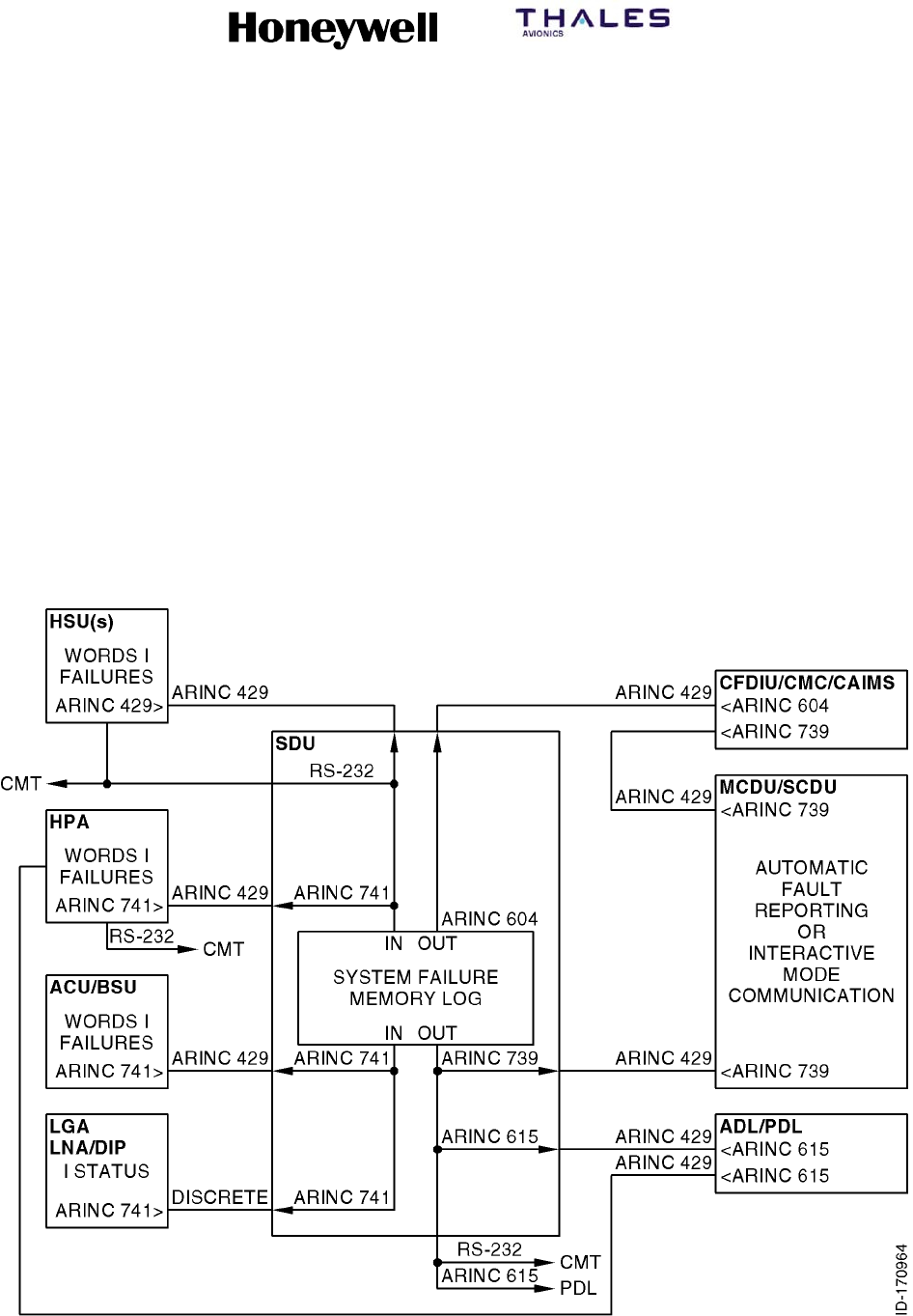
SYSTEM DESCRIPTION, INSTALLATION, AND MAINTENANCE MANUAL
MCS--4200/7200 Multi--Channel SATCOM System
23--20--35 15 Jul 2006
Honeywell International Inc. Do not copy without express permission of Honeywell.
Page 6--1
SECTION 6
TESTING/FAULT ISOLATION
1. Overview
A. General
(1) This section defines the built-in test equipment (BITE) requirements for the MCS
system (i.e., SDU and HPA). Information supplied in this section describes how MCS
system failures are detected, recorded, and reported. See Figure 6-1 for an overview
of the BITE system communications.
(2) System BITE contributes to a number of maintenance functions:
•Detection of internal and external failures
•Storage of in-flight failure data
•Reporting failure status in the air and on the ground
•Ground test capability for isolating faulty LRUs, performance verification, and
system level testing.
Figure 6-1. System BITE Communication

SYSTEM DESCRIPTION, INSTALLATION, AND MAINTENANCE MANUAL
MCS--4200/7200 Multi--Channel SATCOM System
23--20--35 15 Jul 2006
Honeywell International Inc. Do not copy without express permission of Honeywell.
Page 6--2
B. Definitions
(1) Degraded Operation
(a) Degraded operation is defined as the condition when the MCS system is
operating with a failure that results in diminished capability (e.g., some, but not
all channel units available, or less than nominal HPA power available).
(2) Failure
(a) A failure is defined as a fault that persists for a predetermined amount of time or
for a predetermined number of samples. The tolerance on all failure timing
criteria is ±0.5 second.
(3) Intermittent Failure
(a) An intermittent failure is defined as a fault that had been declared a failure,
recovered to its normal valid state, and then is declared to have failed again. A
failure occurrence counter is maintained for each entry in the LRU and system
failure logs to identify intermittent failures.
(4) Fault
(a) A fault is defined as the result of a measurement or comparison that does not
satisfy the test or monitoring result requirements. The test or monitoring result
requirements can require a time element.
(5) Reversion
(a) Reversion is defined as the system response to a failure condition that results in
continued system operation in the presence of the failure, and can result in
degraded system capability.
(6) MCS LRU
(a) The following are defined as the MCS LRUs (i.e., those manufactured by
Honeywell/Thales):
•SDU
•HPA
•HSU.

SYSTEM DESCRIPTION, INSTALLATION, AND MAINTENANCE MANUAL
MCS--4200/7200 Multi--Channel SATCOM System
23--20--35 15 Jul 2006
Honeywell International Inc. Do not copy without express permission of Honeywell.
Page 6--3
C. Failure Detection and Reporting Levels
(1) Failures are detected in the MCS system by a wide variety of tests. The immediate
result of failure detection is usually diagnosis of the failure to a specific component or
functional circuit group, on a specific SRU, in a specific LRU. However, some
detected failures may only be able to be diagnosed to a suspect SRU, or only to a
suspect LRU, or only to a pair or group of LRUs and the physical or logical
interface(s) between them. Three enumerated levels of failure diagnosis are defined
in Table 6-1.
Table 6-1. Levels of Failure
Level Description
Level I Diagnosis to the LRU level or its equivalent (e.g., a specific inactive bus, error, or
warning)
Level II Diagnosis to the SRU (module or circuit card) level
Level III Diagnosis to the component or functional circuit group level or equivalent (e.g., a
very specific error condition)
(2) All MCS LRUs implement Level I and, where possible, Level II failure detection. Level
I diagnosis primarily supports line maintenance. Front panel displays and automatic
reports to central fault/maintenance systems are only performed to Level I resolution
because they are primarily used to support line maintenance, which is typically limited
to LRU replacement. Level II and Level III diagnosis primarily support shop and
factory maintenance. Level II and Level III failure detection information is stored in
the LRU and system failure logs, and can be displayed on the commissioning and
maintenance terminal (CMT) pages.
D. LRU Coverage
(1) The LRU coverage is defined as the sum of all component failure rates covered by
the BITE circuitry within an LRU, divided by the total of the component failure rates
within that LRU. This coverage is greater than or equal to 0.95 as defined. The LRU
probability of false detection is defined as the sum of all component failure rates of
the BITE circuitry within an LRU divided by the total of the component failure rates
within that LRU. This coverage is greater than 0.01 as defined. The LRU coverage
includes the following:
•All SDU to avionic interfaces, where possible
•All MCS inter-LRU interfaces
•All power supply voltages
•All battery voltages
•All microprocessors/microcontrollers
•All memory devices (RAM, ROM, etc).
(2) All discrete drivers between the SDU and the avionics LRUs have over current
protection and open-circuit detection.

SYSTEM DESCRIPTION, INSTALLATION, AND MAINTENANCE MANUAL
MCS--4200/7200 Multi--Channel SATCOM System
23--20--35 15 Jul 2006
Honeywell International Inc. Do not copy without express permission of Honeywell.
Page 6--4
E. Monitoring and Testing Functions
(1) General
(a) The declaration of an inactive input bus takes precedence over declaration of
one or more data word failures against the LRU driving that bus (i.e., if the bus is
inactive, additional logging and reporting of low-rate failures of individual data
words on that bus are precluded). The failure and recovery criteria is set to make
sure individual data word failures are not declared when the bus is inactive. This
is typically done by setting inactive bus failure criteria (e.g., three seconds) to be
faster than word update rate failure criteria (e.g., five seconds), and inactive bus
recovery criteria (e.g., two seconds) to be longer than word update rate recovery
criteria (e.g., one second).
(b) Unless an LRU providing ARINC 429 data declares itself to have failed, a fault is
declared against that LRU when the ARINC 429 data is faulty. This is determined
by checking (as appropriate for each word) for data inconsistencies, data
out-of-range, uses of undefined or reserved values, and occurrences of the
failure warning state in the sign/status matrix (SSM) field.
(c) Two basic types of failure detection testing performed are: functional tests and
continuous monitoring (CM). The purpose of functional testing in the form of
power-on self test and person-activated self test is to exercise the equipment in a
manner as closely as possible to its normal operation. Failures detected during
functional testing are declared to be current failures until a subsequent functional
test shows the failure condition has recovered.
(d) The purpose of continuous monitoring is to test the equipment in a nondisruptive
manner while it is performing its normal operations. Such testing usually includes
monitoring the power supply voltages, temperature sensors, bias currents, input
bus activity, buffer overflow, input data failures, etc. This testing can also include
abnormal failures that cannot be tested as part of the functional testing, such as
protocol failures, processor instruction traps, data loader problems, etc.
(2) Power-On Self-Test
(a) General
1The power-on self-test (POST) is a series of functional tests for individual
LRUs; each MCS LRU performs its own internal POST upon a cold start. A
cold start is defined as the response of an LRU where no retention of any
previously stored information in any volatile memory is assumed. The power
supply provides signals to help an orderly power-down and power-up
process for the LRU during power interrupts of any length. Primary power
interrupts of less than 5 milliseconds duration have no effect on system
operation. For primary power interrupts longer than 5 milliseconds and up to
200 milliseconds duration, the LRU maintains normal operation, except the
RF transmit and receive processes do not need to be supported in any LRU
during this interval. For primary power interrupts greater than 200
milliseconds duration that causes normal operation to cease, the LRU
performs a cold start following restoration of primary power.

SYSTEM DESCRIPTION, INSTALLATION, AND MAINTENANCE MANUAL
MCS--4200/7200 Multi--Channel SATCOM System
23--20--35 15 Jul 2006
Honeywell International Inc. Do not copy without express permission of Honeywell.
Page 6--5
2The POST sequence of tests does not terminate when an out-of-tolerance
condition is encountered. Instead, the sequence continues to complete as
many tests as possible to record all available information regarding existing
failures. An individual LRU that successfully passes POST is declared to be
fully functional. POST must take into account failures detected by
continuous monitoring (i.e., if POST passes, but testing unique to
continuous monitoring has detected and logged a current failure, then the
POST result is logged as a failure).
3After executing its own POST, the SDU commands a system-wide functional
test of the HPA(s), HSU and ACU/BSU(s) (including the HGAs, HGA
diplexer/LNA, and HPR) as applicable for the installed equipment in
accordance with the system configuration pins (see MECHANICAL
INSTALLATION). The SDU then processes the results of the functional tests
from these LRUs. The SDU commands the functional test as follows
through:
•BIT request in the HSU command word
•SSM field of the HPA command word(s) for the HPA
•SSM field(s) for the ACU/BSU control word(s) for the ACU/BSU(s).
4The BITE status from the LGA diplexer/LNA is continuously sent to the SDU,
with no functional test command necessary or possible. Test results from the
HGA(s), HGA diplexer/LNA, and HPR are reported by the ACU/BSU(s).
5The SDU allows up to 30 ±1 seconds for other system LRUs, except the
HSU, which is allowed 60 ±1 seconds to report their POST results following
initiation of a system-wide functional test. If an LRU fails to report its
functional test results within this time period, but otherwise meets the ARINC
429 bus communication rate requirements, the SDU considers that LRU to
have failed. If no ARINC 429 bus communication is received on a particular
bus, the SDU considers that bus to be inactive.
(b) Test Initiation
1The correct operation of much of the internal circuitry of the SDU depends
on clocks derived from the high-stability frequency reference generated by
the oven-controlled crystal oscillator (OCXO). Therefore, it is inappropriate to
perform BITE tests until this clock frequency has achieved gross stability. If
the SDU is powered on after having stabilized at a cold external temperature
(e.g., --55°C), it can take several tens of seconds for the frequency drift rate
to be low enough before the phase locked oscillators (PLO) that derive the
dependent clocks can lock onto the OCXO frequency reference.

SYSTEM DESCRIPTION, INSTALLATION, AND MAINTENANCE MANUAL
MCS--4200/7200 Multi--Channel SATCOM System
23--20--35 15 Jul 2006
Honeywell International Inc. Do not copy without express permission of Honeywell.
Page 6--6
2The SDU defers testing of sensitive equipment until a positive indication of
settling is detected, or sufficient time passes so the lack of settling itself can
be classified as a failure. Deferral of these sections of POST also result in
normal operation being deferred, including access to the user interfaces
(SCDU, CFDS, and CMT) and all automatic calibration processing.
Consequently, the SDU suspends POST until the SDU detects the first of
the following conditions:
•OCXO heater monitor indicates it has achieved operating temperature.
•Power supply unit (PSU) temperature sensor indicates a reading above
25 °C.
•Channel filter module transmit and receive PLO lock detectors both
indicate that lock has been achieved.
•More than 4 minutes have elapsed since primary power was applied.
(c) LRU Front Panel LED and Alphanumeric Display Tests
1A test of the HPA and HSU front panel LEDs is performed as a part of each
POST. At a minimum, this is made up of flashing the LEDs on and off. The
LED flashing continues until POST is completed or for 3 ±0.5 seconds.
During the test, the SDU tests its alphanumeric display by incorporating one
or more occurrences of the word TESTING into its display sequence to
make sure all display elements are tested.
(d) RF Loop Back Tests
1As part of the system-wide POST, the SDU implements a RF loop back test.
The RF loop back occurs in the radio frequency module (RFM) installed in
the SDU.
2The SDU delays initiating the RF loop back test until it receives an indication
the RF loop back has been activated. If the SDU fails to receive a valid
indication within 30 seconds following the RF loop back request, then the
SDU completes its POST without executing the RF loop back test. The SDU
cancels the RF loop back request when the loop back test is completed, or if
the 30 second timer expires while waiting for verification of an active RF loop
back.
(3) Person-Activated Self-Test
(a) The person-activated self-test (PAST) performs the same functions as POST.
PAST is initiated in the HPA and the HSU by pushing the PUSH-TO-TEST (PTT)
switch on the respective LRU front panel. PAST can also be initiated any time
through:
•Respective CMT interface to the LRU
•SSM field of the HPA command word sent to the HPA from the SDU
•BIT request in HSU command word sent to the HSU from the SDU.

SYSTEM DESCRIPTION, INSTALLATION, AND MAINTENANCE MANUAL
MCS--4200/7200 Multi--Channel SATCOM System
23--20--35 15 Jul 2006
Honeywell International Inc. Do not copy without express permission of Honeywell.
Page 6--7
(b) A stuck switch on the CMT or LRU front panel does not cause PAST to remain
active. Any switch activity is ignored while PAST (or POST) is executing.
(c) The HPA and HSU inhibit PAST while the aircraft is airborne, except when PAST
is initiated through the CMT, which is permitted at any time. The HPA and HSU
cannot properly function if not receiving valid command words from the SDU
containing the air/ground status and command information. Under these
conditions, the HPA and HSU are not usable by the SDU. PAST is only permitted
while the aircraft is on the ground, or when the airborne/on-ground status is
unknown. In lieu of the airborne/on-ground status information from the SDU, the
HPA and HSU permit PAST as though the aircraft is on the ground.
(d) A system-wide PAST is initiated in the SDU when commanded by:
•Entry through the SATCOM control and display unit (SCDU)
•Entry through the central maintenance computer (CMC)
•Entry through the central fault display system (CFDS)
•Command from the CMT
•Activating the PTT switch (SDU TEST) on the front panel.
(e) A stuck switch on the SDU front panel does not cause PAST to remain active.
Any switch activity is ignored while PAST (or POST) is executing.
(4) Continuous Monitoring
(a) Continuous monitoring (CM) of the BITE circuitry does not interfere with the
normal operation of the system. Instead any failure condition is recorded and
reported. Continuous monitoring operates as a background task at all times,
even during functional testing. Functional test failure codes that are identical to
the continuous monitoring codes (except for the MSB of the level 3 code)
indicate cases where the functional test differs in some way from the companion
CM test. Those CM failures detected during functional testing (e.g., maintenance
and status word failures) are logged as CM failures, not functional failures.
F. Failure Recording
(1) The SDU records CFDS internal failures at all times. The SDU only records CFDS
external failures while receiving a valid All Call DC1 Command if a Douglas or Airbus
CFDS is installed. Internal failures are defined as those internal to the SATCOM
subsystem. External failures are defined as those external to the SATCOM
subsystem. If a Boeing CMC (or no CFDS) is installed or if valid DC commands are
not available, then the air/ground status is used to generate pseudo DC states of
DC0 (aircraft on-ground) and DC1 (aircraft airborne).
(2) The HPA records internal failures at all times. The HPA only records external failures
while the aircraft is airborne, based on the status of the weight-on-wheels discrete
(on-ground vs. airborne). Internal failures are defined as those that have the same
Level I code as the LRU recording the failure (i.e., 01 for the SDU, 04 for the HGA
HPA, and 07 for the LGA HPA). External failures are defined as those failures not
having the same level 1 code as the LRU recording the failure.

SYSTEM DESCRIPTION, INSTALLATION, AND MAINTENANCE MANUAL
MCS--4200/7200 Multi--Channel SATCOM System
23--20--35 15 Jul 2006
Honeywell International Inc. Do not copy without express permission of Honeywell.
Page 6--8
(3) The HPA and HSU store their functional test and CM failure records in nonvolatile
memory designated as the LRU failure memory log. Each LRU failure memory log is
capable of being interrogated and cleared. The SDU contains a nonvolatile memory
that serves as a system failure memory log. Functional test results supplied by the
HSU, HPA(s), ACU/BSU(s), LGA diplexer/LNA, and the SDU itself are recorded in
this system failure memory log. The system failure memory log is capable of being
interrogated and cleared for each LRU individually. Each LRU failure memory log and
the system failure memory log is capable of recording at least 1000 failures.
(4) The HPA, HSU and other system LRUs supply failure information to the SDU for
storage in the system failure memory log. In the absence of any detected failures
during a flight leg, the SDU records the flight leg counter, flight number, ICAO
address, date, and Greenwich Mean Time (GMT) at the flight leg transition. The SDU
also records the aircraft identification for display on the SCDU and CFDS
maintenance pages.
(5) Class -- The SDU declares and stores the classification (Airbus/Douglas CFDS) of
failure (one, two, three) for each entry in this field.
•Class 1 failures are indicated in flight to the crew by the CFDS because they have
operational consequences for the current or next flight(s).
•Class 2 failures are not automatically indicated in flight to the crew by the CFDS
because they have no operational consequences for the current or next flight(s),
but are indicated to the crew on the ground because they cannot be left
uncorrected until the next routine scheduled maintenance check.
•Class 3 failures are not indicated to the flight crew because they can be left
uncorrected until a routine scheduled maintenance check. An accumulation of
Class 3 failures can lead to a Class 2 or Class 1 failure.
•Aircraft Identification -- The aircraft identification (i.e., the tail number) is made up
of nine alphanumeric characters. The SDU obtains the aircraft identification from
the CMC or CFDS through ARINC labels 301, 302, and 303 (if available).
G. Failure Reporting
(1) General
(a) Active failures include those internal and external failures deemed to be currently
failing while the aircraft is on the ground or airborne. Unlike failure recording that
excludes recording external failures while on the ground, failure reporting has its
own set of criteria as specified in the following paragraphs.
(2) HPA Failure Reporting
(a) General
1The HPA reports its functional test/CM failure status by lighting its front panel
LEDs, and through communication to the SDU.
(b) HPA Front Panel Indicators and Controls
1The HPA indicators and controls are given in Table 6-2.
SYSTEM DESCRIPTION, INSTALLATION, AND MAINTENANCE MANUAL
MCS--4200/7200 Multi--Channel SATCOM System
23--20--35 15 Jul 2006
Honeywell International Inc. Do not copy without express permission of Honeywell.
Page 6--9
Table 6-2. HPA Indicators/Controls
Indicator/Control Description
PASS LED Shows green after a test, if no failures are detected in the HPA
FAIL LED Shows red after a test, if failures are detected in the HPA
PUSH--TO--TEST (PTT) Push this button to start a test of the HPA
(c) HPA Front Panel LEDs
1Functional testing effectively controls the on/off state of the front panel LEDs
during the period beginning with initiation of the functional testing
(POST/PAST), through execution of the functional test sequences (including
LED testing), and up to and including the indication of the test results on the
LEDs. Continuous monitoring exclusively controls the LEDs at all other
times.
2The green LED (PASS) lights for 30 ±5 seconds at the conclusion of the
functional test sequences if both of the following are true:
•The HPA determines there are no currently active CM failures having its
own Level I code (i.e., 04 or 07, as applicable)
•No functional test failures have been detected with its own Level I code.
3There must be no known failures in order to light the green LED as the
functional test indication.
4The red LED (FAIL) lights continuously during the functional test indication
phase and through the transition to the CM indication phase, if the HPA
detects at least one currently active CM failure with its own Level I code. If
the HPA detects only functional test failures (i.e., no CM failures are
currently active), the red LED lights for 30 ±5 seconds and is then turned
off.
5The red LED also lights as long as the failure persists, if the HPA detects
any CM failure that has its own Level I code while continuous monitoring is
controlling the LEDs. Otherwise, both LEDs are turned off. Continuous
monitoring itself never causes the green LED to light. The presence or
absence of functional test failures does not affect the CM indication.
(d) HPA-SDU Communication
1The HPA communicates its functional testing/CM failure status to the SDU
through the HPA maintenance and status words. The HPA only indicates a
FW SSM state in its maintenance and status words, and active discrete
failure bits in its maintenance word. Since no failures unique to functional
testing activate the SSM FW state or the discrete failure bits in the
maintenance word, no functional test failures need to be latched until the
next functional testing sequence.
SYSTEM DESCRIPTION, INSTALLATION, AND MAINTENANCE MANUAL
MCS--4200/7200 Multi--Channel SATCOM System
23--20--35 15 Jul 2006
Honeywell International Inc. Do not copy without express permission of Honeywell.
Page 6--10
2For certain failures detected during continuous monitoring, the appropriate
discrete failure bits and the SSM FW state are set within the maintenance
and status words as long as the failure persists.
(3) HSU Failure Reporting
(a) General
1The HSU reports its functional test/CM failure status by lighting its front
panel LEDs, and through communication to the SDU.
(b) HSU Front Panel Indicators and Controls
1The HSU indicators and controls are given in Table 6-3.
Table 6-3. HSU Indicators/Controls
Indicator/Control Description
PASS LED Shows green after a test, if no failures are detected in the HSU
FAIL LED Shows red after a test, if failures are detected in the HSU
PUSH--TO--TEST (PTT) Push this button to start a test of the HSU
(c) HSU Front Panel LEDs
1Functional testing effectively controls the on/off state of the front panel LEDs
during the period beginning with initiation of the functional testing
(POST/PAST), through execution of the functional test sequences (including
LED testing), and up to and including the indication of the test results on the
LEDs. Continuous monitoring exclusively controls the LEDs at all other
times.
2The green LED (PASS) lights for 30 ±5 seconds at the conclusion of the
functional test sequences if both of the following are true:
•The HSU determines there are no currently active CM failures having its
own Level I code (i.e., 03)
•No functional test failures have been detected with its own Level I code.
3There must be no known failures in order to light the green LED as the
functional test indication.
4The red LED (FAIL) lights continuously during the functional test indication
phase and through the transition to the CM indication phase, if the HSU
detects at least one currently active CM failure with its own Level I code. If
the HSU detects only functional test failures (i.e., no CM failures are
currently active), the red LED lights for 30 ±5 seconds and is then turned
off.

SYSTEM DESCRIPTION, INSTALLATION, AND MAINTENANCE MANUAL
MCS--4200/7200 Multi--Channel SATCOM System
23--20--35 15 Jul 2006
Honeywell International Inc. Do not copy without express permission of Honeywell.
Page 6--11
5The red LED also lights as long as the failure persists, if the HSU detects
any CM failure that has its own Level I code while continuous monitoring is
controlling the LEDs. Otherwise, both LEDs are turned off. Continuous
monitoring itself never causes the green LED to light. The presence or
absence of functional test failures does not affect the CM indication.
(d) HSU-SDU Communication
1The HSU communicates its functional testing/CM failure status to the SDU
through the HSU status word. The HSU indicates a FW SSM state in its
status word, when failures are present that prevent it from offering HSD
service.
2For certain failures detected during continuous monitoring, the appropriate
discrete failure bits and the SSM FW state are set within the maintenance
and status words as long as the failure persists.
(4) SDU Failure Reporting
(a) General
1The SDU reports its functional testing/CM failure status and all other system
LRUs by:
•Activating its alphanumeric display
•Communicating to the SCDU, CMC, CFDS, and CMT interfaces.
2The alphanumeric display indicates all applicable failure conditions with no
regard to:
•Any type of internal/external failure differentiation
•Any CFDS failure class distinctions
•Which LRU detected a failure (either the SDU itself or one of the reporting
LRUs in the SATCOM subsystem).
3The SDU delays reporting the results of the functional test sequence for a
period of 5 seconds. This gives continuous monitoring the opportunity to
perform its unique tests during the delay period, and include any current CM
failures in the test report. The SDU takes a snapshot at the end of the
functional test delay period to include all currently active CM failures in
addition to all failures detected during functional testing. The functional test
delay period applies to the SDU alphanumeric display, the SCDU
maintenance pages, the CFDS pages, and the CAIMS and CMC fault
summary words, but not to the CMT.
(b) SDU Front Panel Indicators and Controls
1The SDU indicators and controls are given in Table 6-4.

SYSTEM DESCRIPTION, INSTALLATION, AND MAINTENANCE MANUAL
MCS--4200/7200 Multi--Channel SATCOM System
23--20--35 15 Jul 2006
Honeywell International Inc. Do not copy without express permission of Honeywell.
Page 6--12
Table 6-4. SDU Indicators/Controls
Indicator/Control Description
SDU TEST Push this button to initiate a system--wide SATCOM test
SYSTEM STATUS DISPLAY Shows data defining the SATCOM system configuration and the
identification of all SATCOM components that are not operating as required
MANUAL SCROLL Push this button to scroll through the messages on the system status
display
(c) Front Panel Alphanumeric Display and MANUAL SCROLL Button
1General
aThe alphanumeric display makes it easy for the maintenance personnel
to identify which system LRU has failed. The alphanumeric display is
blank unless specifically activated for temporary display of failure
messages and other status information. The alphanumeric display is
also kept blank under conditions of extreme temperatures. The display
is not intended to be started when its temperature is less than --5 °C, or
greater than +30 °C. The alphanumeric display is started during the LED
test portion of the functional test sequence. After the functional test
delay period, and any time during continuous monitoring, the
alphanumeric display can be started by pushing the MANUAL SCROLL
button.
bThe operator can scroll the alphanumeric display through the entire
applicable message sequence by repeatedly pushing the MANUAL
SCROLL button within 30 5 seconds after the display is started. One
left-justified 20-character (or less) message is displayed each time the
MANUAL SCROLL button is pushed. When the end of the display
sequence is reached (i.e., END OF LIST), the next actuation of the
MANUAL SCROLL button returns the alphanumeric display to the top of
the display sequence, enabling the operator to scroll through the
sequence again. Message scrolling is performed according to the
following sequence:
•One of four possible system/SDU pass/fail messages
•All applicable Level I failure messages
•LRU part number messages (up to four lines)
•ORT identification message
•END OF LIST message.
cIf the MANUAL SCROLL button is inactivate for 30 ±5 seconds at any
point during the display sequence, the alphanumeric display is blanked
and any display sequence in progress is aborted. At the same time, one
or both of the front panel LEDs (as appropriate) are turned off if they
were exclusively indicating functional test failures with no current CM
failures.

SYSTEM DESCRIPTION, INSTALLATION, AND MAINTENANCE MANUAL
MCS--4200/7200 Multi--Channel SATCOM System
23--20--35 15 Jul 2006
Honeywell International Inc. Do not copy without express permission of Honeywell.
Page 6--13
2SYSTEM/SDU PASS/FAIL Message
aThis one-line message, which summarizes the overall functional test or
CM status, takes on one of four possible states:
•SDU PASS SYS PASS
•SDU PASS SYS FAIL
•SDU FAIL SYS PASS
•SDU FAIL SYS FAIL.
3Level I Failure Messages
aThis section lists all the applicable Level I failure messages that can be
displayed on the alphanumeric display, along with the appropriate LRU
or control bus input. These messages are listed in failure code order in
Table 6-5. For the functional test display, the message list includes all
the active failures in the snapshot and the list is static.
bFor continuous monitoring, the message list includes all currently active
CM failures. The presence or absence of functional test failures does
not affect the CM message list. The failure message list for the CM
display is potentially dynamic.
cDuring continuous monitoring, if a new CM failure becomes active
during the scroll sequence, the respective message appears at its
proper location in the sequence according to its Level I code. This
occurs either during the current scroll sequence if that Level I code has
not yet been reached, or during the next scroll sequence if the failure is
still active. If a CM failure recovers during a scroll sequence, its
message does not appear in any subsequent scroll sequence, even if it
had appeared earlier. If a CM failure recovers while its particular
message is currently being displayed, the message continues to be
displayed until the MANUAL SCROLL button is activated or until the
time-out period expires.
Table 6-5. Level 1 Failure Messages
Level 1
Code Failure Message Description
AES LRU Failures:
00 (not applicable) Unknown Level I failure
01 SDU SDU failed
02 OTHER SDU Other SDU (of a dual system) failed
03 HSU HSU failed
04 HPA--HI GAIN High Gain Antenna HPA failed

SYSTEM DESCRIPTION, INSTALLATION, AND MAINTENANCE MANUAL
MCS--4200/7200 Multi--Channel SATCOM System
23--20--35 15 Jul 2006
Honeywell International Inc. Do not copy without express permission of Honeywell.
Page 6--14
Table 6-5. Level 1 Failure Messages (cont)
Level 1
Code DescriptionFailure Message
07 HPA--LO GAIN Low Gain Antenna HPA failed
0A HI POWER RELAY HPR (antenna system) failed
0D DLNA--(TOP/L) Top/Port Diplexer/Low Noise Amplifier failed
0F DLNA--R Starboard Diplexer/Low Noise Amplifier failed
10 DLNA--LO GAIN LGA Diplexer/Low Noise Amplifier failed
13 BSU--(TOP/L) Top/Port BSU or ACU failed
15 BSU--R Starboard BSU failed
1A HI GAIN ANT--(TOP/L) Top/Port HGA failed
1C HI GAIN ANTENNA--R Starboard HGA failed
1F LO GAIN ANTENNA LGA failed
21 SCDU1 or WSC1 No. 1 SCDU or WSC failed
22 SCDU2 or WSC2 No. 2 SCDU or WSC failed
23 SCDU3 or WSC3 No. 3 SCDU or WSC failed
Non-AES LRU Failures:
33 (ACARS MU/CMU)1 No. 1 AFIS/ACARS unit failed
34 (ACARS MU/CMU)2 No. 2 AFIS/ACARS unit failed
35 IRS--PRI Primary IRS failed
36 IRS--SEC Secondary IRS failed
39 (CFDIU/CMC) CFDS/CMC failed
3D FMC1 No. 1 FMC failed
3E FMC2 No. 2 FMC failed
40 ARINC 429 ICAO ADDR 429 ICAO address source failed
41 (not applicable) Discrete cockpit indicators failed
42 CTU Cabin telecommunications unit failed
43 (CFS/CPDF) Cabin file server/cabin packet data function failed
Inactive BITE Bus Input to SDU from other LRU:
50 HSU/SDU HSU bus
52 (CFS/CPDF)/SDU Cabin file server/cabin packet data function bus
53 (ACARS MU/CMU)1/SDU No. 1 AFIS/ACARS unit bus

SYSTEM DESCRIPTION, INSTALLATION, AND MAINTENANCE MANUAL
MCS--4200/7200 Multi--Channel SATCOM System
23--20--35 15 Jul 2006
Honeywell International Inc. Do not copy without express permission of Honeywell.
Page 6--15
Table 6-5. Level 1 Failure Messages (cont)
Level 1
Code DescriptionFailure Message
54 CTU/SDU CEPT--E1 bus from the CCS
55 SCDU1/SDU or
WSC1/SDU
No. 1 SCDU or WSC bus
56 SCDU2/SDU or
WSC2/SDU
No. 2 SCDU or WSC bus
57 (ACARS MU/CMU)2/SDU No. 2 AFIS/ACARS unit bus
59 (CFDIU/CMC)/SDU CFDS bus
5A IRS--PRI/SDU Primary IRS bus
5B IRS--SEC/SDU Secondary IRS bus
5C HPA--HI GAIN/SDU High Gain Antenna HPA bus
5F HPA--LO GAIN/SDU Low Gain Antenna HPA bus
62 BSU--(TOP/L)/SDU Top/port BSU bus
64 BSU--R/SDU Starboard BSU bus
65 (not applicable) Radio Management Panel bus
66 SCDU3/SDU or
WSC3/SDU
No. 3 SCDU or WSC bus
71 OTHER SDU/THIS SDU Bus from other SDU in a dual system
73 FMC1/SDU No. 1 FMC bus
74 FMC2/SDU No. 2 FMC bus
Inactive Bus Inputs to other LRU:
90 SDU M--CTRL/HPA--HI Multicontrol bus to HGA HPA from SDU
96 SDU M--CTRL/HPA--LO Multicontrol bus to LGA HPA from SDU
98 SDU M--CTRL/BSU--(T/L) Multicontrol bus to top/port BSU from SDU
9A BSU--R XTALK/BSU--L Crosstalk bus to port BSU from starboard BSU
9C SDU M--CTRL/BSU--R Multicontrol bus to starboard BSU from SDU
9D BSU--L XTALK/BSU--R Crosstalk bus to starboard BSU from port BSU
9E SDU/HSU Control bus to HSU from SDU
A1 SDU/WSC1 Bus to WSC1 from SDU
A2 SDU/WSC2 Bus to WSC2 from SDU
A3 SDU/WSC3 Bus to WSC3 from SDU

SYSTEM DESCRIPTION, INSTALLATION, AND MAINTENANCE MANUAL
MCS--4200/7200 Multi--Channel SATCOM System
23--20--35 15 Jul 2006
Honeywell International Inc. Do not copy without express permission of Honeywell.
Page 6--16
Table 6-5. Level 1 Failure Messages (cont)
Level 1
Code DescriptionFailure Message
Miscellaneous Failures:
A6 HSU ETHERNET PORT 1 No activity on HSU Ethernet port 1
A7 HSU ETHERNET PORT 2 No activity on HSU Ethernet port 2
C0 WRG:STRAPS/SDU System configuration pins error
C1 WOW1/WOW2/SDU Weight on wheels discrete inputs disagree
C2 SDU DUAL SEL/DISABLE Dual system discrete inputs disagree
C3 WRG:ICAO ADDR/SDU ICAO address straps error
C4 TX PATH VSWR--HI GAIN Excessive VSWR load at HGA HPA output
C5 WRG:STRAPS/SDU ORT Configuration pins and ORT settings disagree
C6 TX PATH VSWR--LO GAIN Excessive VSWR load at LGA HPA output
C7 HPA--HI GAIN
OVERTEMP
Over temperature in HGA HPA
C8 BAD GROUND STATION Invalid GES frequency command
C9 HPA--LO GAIN
OVERTEMP
Over temperature in LGA HPA
CA SDU/DLNA--LO GAIN LGA LNA control driver SDU
CB WRG:SDI/HPA--HI GAIN
(see NOTE)
HGA HPA identification strapped incorrectly
CC WRG:SDI/HPA--LO GAIN
(see NOTE)
LGA HPA identification strapped incorrectly
CD SDU (POC/TOTC) SDU power-on counter or total-on-time counter has been reset
CF HPA--HI (POC/TOTC) HGA HPA power-on counter or total-on-time counter has been
reset
D0 HPA--LO (POC/TOTC) LGA HPA power-on counter or total-on-time counter has been
reset
D1 WRG:SDI/HPA--HI GAIN
(see NOTE)
HGA HPA identification strapped incorrectly
D2 WRG:SDI/HPA--LO GAIN
(see NOTE)
LGA HPA identification strapped incorrectly
D3 WRG:SDI/BSU--(T/L) Top/Port BSU identification strapped incorrectly
D4 WRG:SDI/BSU--R Starboard BSU identification strapped incorrectly
D5 HPA--HI GAIN COAX HGA HPA input coax cable
D6 HPA--LO GAIN COAX LGA HPA input coax cable
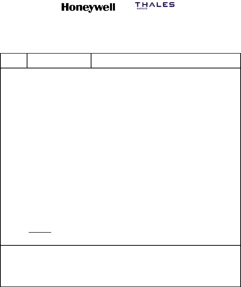
SYSTEM DESCRIPTION, INSTALLATION, AND MAINTENANCE MANUAL
MCS--4200/7200 Multi--Channel SATCOM System
23--20--35 15 Jul 2006
Honeywell International Inc. Do not copy without express permission of Honeywell.
Page 6--17
Table 6-5. Level 1 Failure Messages (cont)
Level 1
Code DescriptionFailure Message
D8 DLNA/(SDU)--(T/L) Top/Port HGA LNA coax cable output to HSU or SDU
D9 DLNA/(SDU)--R Starboard HGA LNA coax cable output to HSU or SDU
DA DLNA/(SDU)--LO GN LGA LNA coax cable output to HSU or SDU
DB LO GAIN SUBSYSTEM LGA log--on functional test failure or could not initiate test
DC NO ACTIVE MU/CMU At least one (C)MU is communicating, but none have declared
themselves active
DD SDU OWNER
REQS--SECD
Error in the secured ORT partition
DE SDU OWNER
REQS--USER
Error in the user ORT partition
DF HI GAIN SUBSYSTEM Slave HGA log--on functional test failure or could not initiate test
E1 BAD HSU DISABLE DISC HSU disable discrete from SDU not functioning
E4 BAD HSU/SDU I/F VER Incompatible interface between HSU and SDU
E6 HSU/HPA TX RF PATH HSU to HPA coax cable
E8 DLNA/HSU RX RF PATH DLNA to HSU coax cable
EC WRG:STRAPS/HSU HSU configuration pins error
ED WRG:STRAPS/HSU ORT HSU configuration pins and SDU ORT settings disagree
EE WRG:FWD ID/HSU HSU forward ID straps error
Undefined:
Others LEVEL 1 FAULT XX XX is the Level 1 failure code (undefined)
NOTE: The front panel display messages associated with failure codes CBx and CCx (WRG:SDI/HPA HI--GAIN and
WRG:SDI/HPA LO--GAIN, respectively) are identical to the messages raised for failure codes D1x and D2x,
respectively. This use of a single front panel display message for multiple failure codes (where the CB/CCx
codes reflect detection by the HGA/LGA HPA of an invalid HPA SDI strap condition, while the D1/D2x codes are
generated by the SDU in response to a report from the HGA/LGA HPA of having detected an unexpected SDI
code) is deliberate, and results from alignment of the front panel display messages with their CFDS/CMC
counterparts. Because of this approach, it is possible (in this specific case) for an operator to receive two
consecutive front panel display messages that are the same.

SYSTEM DESCRIPTION, INSTALLATION, AND MAINTENANCE MANUAL
MCS--4200/7200 Multi--Channel SATCOM System
23--20--35 15 Jul 2006
Honeywell International Inc. Do not copy without express permission of Honeywell.
Page 6--18
4LRU Identification (Part Numbers) Electronically
aFollowing the display of all Level I failure messages, a list of the
available LRU end-item part numbers is displayed. This list only includes
part numbers for those LRUs present in the given installation as defined
by the system configuration pins (see MECHANICAL INSTALLATION).
For an installed LRU whose end-item part number is not available,
dashes are displayed in place of the part number (e.g., HPL______
_____). The list of part numbers are displayed in the order given in
Table 6-6.
Table6-6. ListofPartNumbers
LRU Part No.
SDU SDU bbbbbbb--hhsss--nn
HGA HPA HPH bbbbbbb--hhsss--nn
LGA HPA HPL bbbbbbb--hhsss--nn
HSU HSU bbbbbbb--hhsss--nn
NOTES:
1. bbbbbbb represents the seven-digit LRU end-item base part number.
2. hh represents the two-digit LRU end-item hardware configuration number.
3. sss represents the three-digit LRU end-item software configuration number.
4. nn represents the two-character LRU end-item software modification level (possibly including space, dash
characters, and alpha characters).
bFor the SDU, the two-digit LRU hardware configuration number must be
entered manually through the CMT interface for valid data to be
available for display. This data is stored during LRU end-item testing. All
other numbers reside within the LRU software. All numbers are
communicated to the SDU by Honeywell/Thales HSU and HPA(s)
through the part number block transfer. For non-Honeywell/Thales
interfacing HPAs, no such data is available to the SDU, therefore,
dashes are displayed for the HPA end-item part number.
5ICAO Aircraft Address
aFollowing the display of the LRU End Item part numbers, the ICAO
aircraft address is displayed in octal and hexadecimal formats as shown
below:
ICAO--XXXXXXXX YYYYYY
Where “XXXXXXXX” represents the octal format and “YYYYYY”
represents the hexadecimal format. If the ICAO is provided from an
ARINC 429 source, as determined by the state of configuration pin
TP10A, and a valid ICAO has not been received, the octal and
hexadecimal values are replaced with dashes.

SYSTEM DESCRIPTION, INSTALLATION, AND MAINTENANCE MANUAL
MCS--4200/7200 Multi--Channel SATCOM System
23--20--35 15 Jul 2006
Honeywell International Inc. Do not copy without express permission of Honeywell.
Page 6--19
6HSD Channel ISN
aFollowing the display of the ICAO aircraft address, the Inmarsat Serial
Number (ISN) for each installed HSD channel is displayed as shown
below:
ISNX: YYYYYY ZZZZZZ
Where “X” is a decimal number from 1 to 4 used to distinguish multiple
ISNs, and where “YYYYYY” represents the Type Approval ID and
“ZZZZZZ” the Forward ID. The ISNs for each installed HSD channel are
displayed on a separate line. If the ISN for an installed HSD channel is
not available, dashes are displayed in place of the Type Approval ID
and the Forward ID.
7ORT Identification
aFollowing the display of the ISNs, if one or more HSD channels are
installed, or after the ICAO, if no HSD channels are installed, the user
ORT identification is displayed as specified:
•ORT ID--XXXXXXXXXXXXX (first line)
•XXXXXXXXXXX--MODIFIED (second line, after another activation of
the MANUAL SCROLL button).
bWhere XXXXXXXXXXXXXXXXXXXXXXXX represents the 24-character
description contained in the user ORT description field. The user ORT
description field is used to annotate a particular set of ORT items to
identify one from another (e.g., NORTH PACIFIC ROUTE, SOUTH
ATLANTIC ROUTE, 747--400 ASIAN ROUTE, 777 ASIAN ROUTE).
Alternatively, this item could contain a software identification (e.g., a
software part number for the user ORT as a released entity).
cThe MODIFIED flag is only displayed if the state of the user ORT
modified flag indicates any item in the user ORT has been modified
since the user ORT was created. When any user ORT item is modified
by the SDU software, either directly or indirectly, the user ORT modified
flag is set to MODIFIED. If the state of the user ORT modified flag is
unmodified, the MODIFIED flag is not displayed. The state of the user
ORT modified flag is never set to unmodified by the SDU software.
dThe next two pushes of the MANUAL SCROLL button present the same
information for the Secured ORT partition.
8SDU Temperature
aFollowing the display of the ORT Identification, the SDU temperature is
displayed as shown below:
SDU TEMP (--)XXXC

SYSTEM DESCRIPTION, INSTALLATION, AND MAINTENANCE MANUAL
MCS--4200/7200 Multi--Channel SATCOM System
23--20--35 15 Jul 2006
Honeywell International Inc. Do not copy without express permission of Honeywell.
Page 6--20
Where “XXX” represents the numeric display of the actual SDU
temperature in degrees Celsius, with a (--) sign or space as appropriate
for negative and positive values. The “XXX” field will have leading zeros
replaced by spaces.
9EndOfListMessage
aThe END OF LIST message is displayed at the end of the display list
after the ORT identification.
H. Miscellaneous BITE Requirements
(1) The typical retention period for the BITE memory is at least five years at 25 °C. The
worst case retention period is at least one year at 50 °C. If batteries are used to
supply backup power for the BITE memory, the typical battery lifetime should be at
least 10 years at 25 °C. The worst case lifetime is at least two years at 50 °C.
(2) Each system LRU has a total on-time clock (TOTC) to accumulate and record the
amount of time the LRU has been powered up. The TOTC has a 10 minute
resolution, and is capable of accumulating and recording a count of at least 200,000
hours.
(3) The TOTC value is capable of being examined, and of being reset to 0:00 through
the CMT. Any manual TOTC reset, or any automatic TOTC reset (e.g., upon
detection of corruption of its value), results in an automatic entry of the event into the
LRU failure memory log and the SDU system failure memory log. The TOTC hours
are capable of being automatically entered into the LRUs maintenance activity log.
I. Maintenance Activity Log
(1) A maintenance activity log is stored in each system LRU. The maintenance activity
log is made up of the six most recent maintenance activity records (MAR). Each MAR
can be entered through the CMT. Information is stored in the MAR as shown in
Table 6-7 and in the order listed.
Table 6-7. MAR Information
Field Size Range
Document Number 16 ASCII Characters a--z, A--Z, 0--9
Date (yymmdd) 6 ASCII Numerics yy 00--99
mm 01--12
dd 01--31
Location 32 ASCII Characters a--z, A--Z, 0--9
Phone Number 18 ASCII Numerics 0--9
Total On-Time Clock (Hours) 6 ASCII Numerics 0--200,000

SYSTEM DESCRIPTION, INSTALLATION, AND MAINTENANCE MANUAL
MCS--4200/7200 Multi--Channel SATCOM System
23--20--35 15 Jul 2006
Honeywell International Inc. Do not copy without express permission of Honeywell.
Page 6--21
(2) The fields are defined as follows:
•Document number -- The document number has up to 16 alphanumeric
characters. The intent of this field is to supply maintenance activity traceability.
•Date field -- The date field is made up of six numeric characters in the format of
yymmdd, where yy represents the year, mm represents the month, and dd
represents the day. This field is entered automatically by the SDU as determined
by its internal real-time clock (RTC); it is entered manually for the HPA. The intent
of this field is to record the date the maintenance activity was performed.
•Location field -- The location field has up to 32 alphanumeric characters. The
intent of this field is to indicate the place where the LRU maintenance service was
performed.
•Phone number field -- The phone number field is made up of 18 numeric
characters. The intent of this field is to supply a phone number of who performed
the LRU maintenance. This phone number should include the combination of
country code, area code, and local phone number.
•Total on-time clock field -- The TOTC field is made up of six numeric characters
representing hours. This field is entered automatically by the LRU as determined
by the internal TOTC.
2. SATCOM Control and Display Unit
A. General
(1) The SATCOM Control and Display Unit (SCDU) menu formats obey the accepted
industry standards for multifunction (multipurpose) control and display units (MCDU).
The following paragraphs describe the SCDU display layout and terminology used to
describe the display, font size conventions, scratchpad usage, format, keyboard
usage, display symbols, and update rates.
B. SCDU Display Terminology and Basic Operation
(1) General
(a) The SCDU display is made up of 14 lines of 24 characters. The top line (line 1) is
referredtoasthetitlelineandthebottomline(line14)isreferredtoasthe
scratchpad. Lines 2 thru 13 are arranged into six pairs having a label line and
data line. The SDU communicates to the SCDU for all data to be displayed in
green. The color displayed on the MCDU depends on how the MCDU responds
to this communication.
(b) There are six line select (LS) keys on each side of the SCDU display designated
left (L) and right (R) and numbered 1 to 6 from top to bottom. The LS keys are
associated with a pair of display lines where the upper line of a pair is the label
line and the lower line is the data line. The LS key/line pair relations are given in
Table 6-8.

SYSTEM DESCRIPTION, INSTALLATION, AND MAINTENANCE MANUAL
MCS--4200/7200 Multi--Channel SATCOM System
23--20--35 15 Jul 2006
Honeywell International Inc. Do not copy without express permission of Honeywell.
Page 6--22
(c) The SCDU can display a large and small font size. Different character fonts are
not shown in the example SCDU page figures given in this section. The use of
large font is indicated by the presence of uppercase letters in the SCDU page
figures, while the use of small fonts are demonstrated by lowercase letters. In
general, page names displayed in the title line are in large font. For pages where
p/t is specified to be displayed in the title line, the p/t is in small font. Data
entered into the scratchpad is displayed in large font. Data in the label lines is
displayed in small font, while data in the data lines is displayed in large font.
Numerical character font sizes cannot be shown in the figures, but their font
sizes follow the same conventions.
Table 6-8. LS Key/Line Pair Relations
LS Keys Display Lines
1L -- 1R 2 and 3
2L -- 2R 4 and 5
3L -- 3R 6 and 7
4L -- 4R 8 and 9
5L -- 5R 10 and 11
6L -- 6R 12 and 13
(d) Labels on the left side of the SCDU display are displayed beginning in column 2
of the label line. Data on the left side is left-justified in the data line. Labels and
data on the right side of the SCDU display is right-justified. This is the case
unless specified otherwise.
(2) Scratchpad
(a) General
1The scratchpad is used for data entry and displaying SDU generated
messages. Pushing an alphanumeric key on the keypad (0 through 9, A
through Z, +/-- [plus or minus], / [slash, space]) enters that character into the
scratchpad. The scratchpad is not used for fixed format display purposes.
The mechanism used for data entry is described below.

SYSTEM DESCRIPTION, INSTALLATION, AND MAINTENANCE MANUAL
MCS--4200/7200 Multi--Channel SATCOM System
23--20--35 15 Jul 2006
Honeywell International Inc. Do not copy without express permission of Honeywell.
Page 6--23
(b) Data Entry
1When the user types the appropriate characters using the SCDU keypad,
the characters are echoed on the scratchpad. After data entry, the user must
push the appropriate LS key adjacent to the data field where the data is to
be displayed. The SDU then checks the data for format and acceptability
(out-of-range, entry not permitted into the field, etc). If the data is incorrect,
the SDU leaves the previous data in the field and displays the appropriate
error message in the scratchpad. If any LS key is pushed adjacent to a
blank or nonselectable field, the scratchpad message 1 (i.e., NOT
ALLOWED) is issued. If the entry was rejected because an incorrect LS key
was pushed, the entry is accepted if the correct LS key is subsequently
pushed.
(c) Scratchpad Message
1If the SDU determines a data entry does not conform to format or
acceptability requirements after an entry is attempted, the SDU issues a
scratchpad message prompting the user for the correct data. The user can
clear a scratchpad message by using the clear (CLR) key, or by entering
data into the scratchpad over the message.
(d) CLR and DEL Keys
1General
aThe CLR and delete (DEL) keys are used to clear the scratchpad and
alter the data fields. Generally, for MCDUs that have only a CLR key
(e.g., Airbus and Douglas) the scratchpad is cleared and the data fields
are altered by using this key. For MCDUs that have both CLR and DEL
keys (e.g., Boeing), the scratchpad is cleared using the CLR key, while
the data fields are altered using the DEL key.
2CLR Key
aPushing the CLR key clears the scratchpad message. When the
scratchpad contains user-entered characters, momentary actuation of
the CLR key clears the last entered character, while continual actuation
of the CLR key clears the entire contents of the scratchpad.
bWhen the scratchpad is empty, pushing the CLR key causes CLR to be
displayed in the scratchpad indented five spaces. If an LS key is pushed
and the field adjacent to the LS key is specified to be either erasable
(e.g., an unprotected number) or a default maintained value (e.g.,
protected number priorities), the field is cleared or reverts back to its
default value, as applicable.
cFor compatibility with the Boeing 777 AIMS/CDU, the SDU clears the
entire scratchpad when the CLR command is received with the repeat
bit set.

SYSTEM DESCRIPTION, INSTALLATION, AND MAINTENANCE MANUAL
MCS--4200/7200 Multi--Channel SATCOM System
23--20--35 15 Jul 2006
Honeywell International Inc. Do not copy without express permission of Honeywell.
Page 6--24
3DEL Key
aThe DEL key (if available) can be used to clear or revert the data fields.
Pushing the DEL key causes no response when the scratchpad is not
empty, except for either an SDU issued error message or pilot-entered
characters.
bWhen the scratchpad is empty, pushing the DEL key causes DELETE to
be displayed in the scratchpad.
NOTE: Pushing the DEL key again does not clear DELETE from the
scratchpad. Instead, pushing the CLR key when DELETE is
displayed in the scratchpad clears DELETE.
cIf an LS key is pushed and the field adjacent to the LS key is specified
to be either erasable (e.g., an unprotected number) or a default
maintained value (e.g., protected number priorities), the field is cleared
or reverts back to its default value, as applicable.
dWhen the scratchpad contains CLR indented five spaces as the result of
the CLR key being pushed with an empty scratchpad and the DEL key
is subsequently pushed, the SDU replaces CLR with DELETE in the
scratchpad.
(e) NEXT PAGE and PREV PAGE Keys
1General
aPushing the NEXT PAGE and PREV PAGE (if available) function keys
on the SCDU keypad causes the SDU to display the next page, or
previous page of the display sequence where appropriate (i.e., when p/t
is displayed in the title line).
2NEXT PAGE Key
aPushing this key causes the next page in the sequence to be displayed.
If the last page in a multiple page sequence is displayed and the NEXT
PAGE key is pushed, the first page is displayed. The SDU ignores this
key if the key is pushed when p/t is not displayed, or if a p/t display is
the value 1/1.
3PREV PAGE Key
aPushing this key causes the previous page in the sequence to be
displayed. If the first page in a multiple page sequence is displayed and
the PREV PAGE key is pushed, the last page is displayed. The SDU
ignores this key if the key is pushed when p/t is not displayed, or if a p/t
display is the value 1/1.
(f) Special Symbols
1When displayed, special symbols are defined as given in Table 6-9.
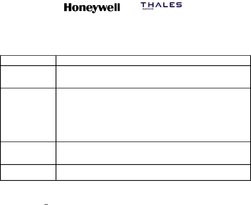
SYSTEM DESCRIPTION, INSTALLATION, AND MAINTENANCE MANUAL
MCS--4200/7200 Multi--Channel SATCOM System
23--20--35 15 Jul 2006
Honeywell International Inc. Do not copy without express permission of Honeywell.
Page 6--25
Table 6-9. Special Symbols
Symbol Description
* (Asterisk) Pushing the LS key adjacent to this symbol (when it appears) causes an
action of some kind to occur (e.g., making a phone call, sorting a phone
list, or initiating log-off).
[ ] (Brackets) Empty brackets prompt the user for data entry into the field. However, data
entry is not mandatory. Brackets surrounding data indicate the data is
unprotected and can be modified or deleted. Not all fields modifiable are
surrounded by brackets. When brackets are used to enclose existing data,
as opposed to prompting entry of data into an empty field, they are
intended as an indication the data is unprotected (i.e., an unprotected
phone number). Conversely, protected phone numbers do not have
brackets, indicating the phone number cannot be modified or deleted.
<,>(Carets) A caret adjacent to an LS key indicates if the key is pushed the display
changes to a new page. The new page is either the one indicated next to
the caret or, in case of RETURN>, the higher level page.
<SEL> Indicates the data in the field is currently selected (e.g., the selected GES
or antenna).
(g) Updates
1Dynamically generated display fields, whose contents have changed, are
updated by the SDU both periodically (at a rate of at least 1 Hz), and upon
completion of an LS key action that could have caused the display or the
display field to change. With multiple SCDU configurations, the SDU only
maintains one version of each page for display. The SDU responds to LS
key actuations from all SCDUs in a serial fashion and updates the display
page(s). Each SCDU scratchpad and the channel selection fields are
independent from all others, allowing each user to perform independent
actions.
C. SCDU Page Hierarchy
(1) The SCDU page hierarchy is shown in Figure 6-2. The SATCOM MAIN MENU page
is accessed by pushing the LS key adjacent to <SAT for single SDU installations.
Highlighted blocks in Figure 6-2 represent maintenance pages that are discussed in
detail in paragraph D. Refer to the appropriate MCS SATCOM System Guide for
additional non highlighted SATCOM displays.
D. SCDU Pages
(1) SATCOM MAIN MENU Page
(a) Access to this page is from the MCDU MAIN MENU page. The purpose of this
page is to display call status information, to optionally make, answer, and
terminate calls, and to supply access to lower level pages. See Figure 6-3 for
example pages.

SYSTEM DESCRIPTION, INSTALLATION, AND MAINTENANCE MANUAL
MCS--4200/7200 Multi--Channel SATCOM System
23--20--35 15 Jul 2006
Honeywell International Inc. Do not copy without express permission of Honeywell.
Page 6--26
Blank Page
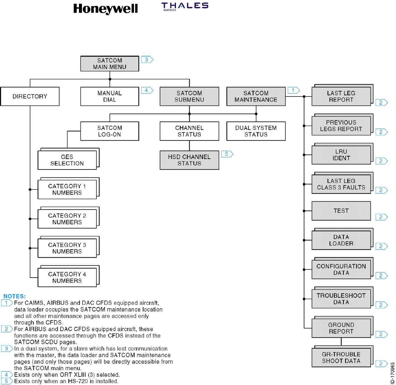
SYSTEM DESCRIPTION, INSTALLATION, AND MAINTENANCE MANUAL
MCS--4200/7200 Multi--Channel SATCOM System
23--20--35 15 Jul 2006
Honeywell International Inc. Do not copy without express permission of Honeywell.
Page 6--27/6--28
Figure 6-2. SATCOM SCDU Page Hierarchy
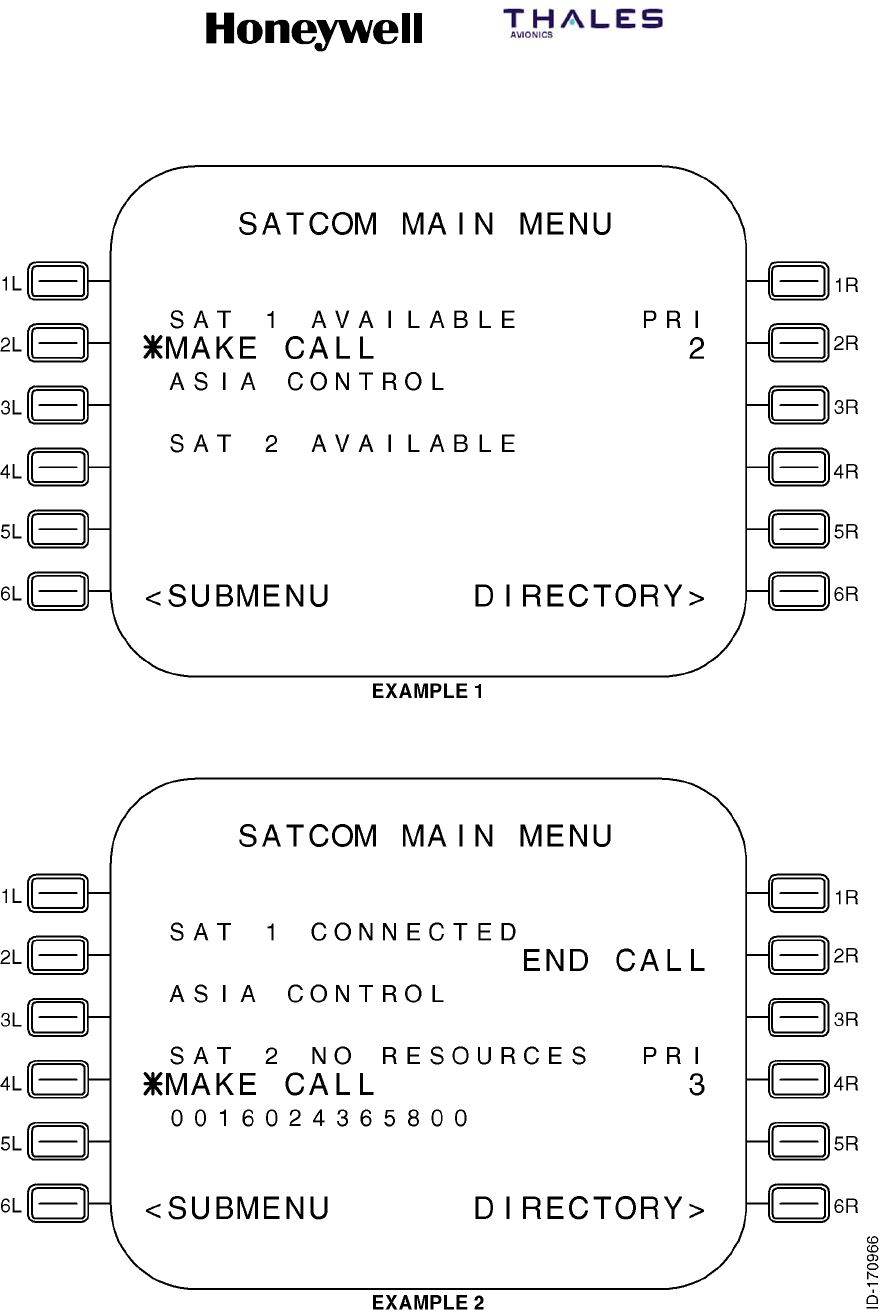
SYSTEM DESCRIPTION, INSTALLATION, AND MAINTENANCE MANUAL
MCS--4200/7200 Multi--Channel SATCOM System
23--20--35 15 Jul 2006
Honeywell International Inc. Do not copy without express permission of Honeywell.
Page 6--29
Figure 6-3 (Sheet 1, Boeing/Corporate). SATCOM SCDU Main Menu Page
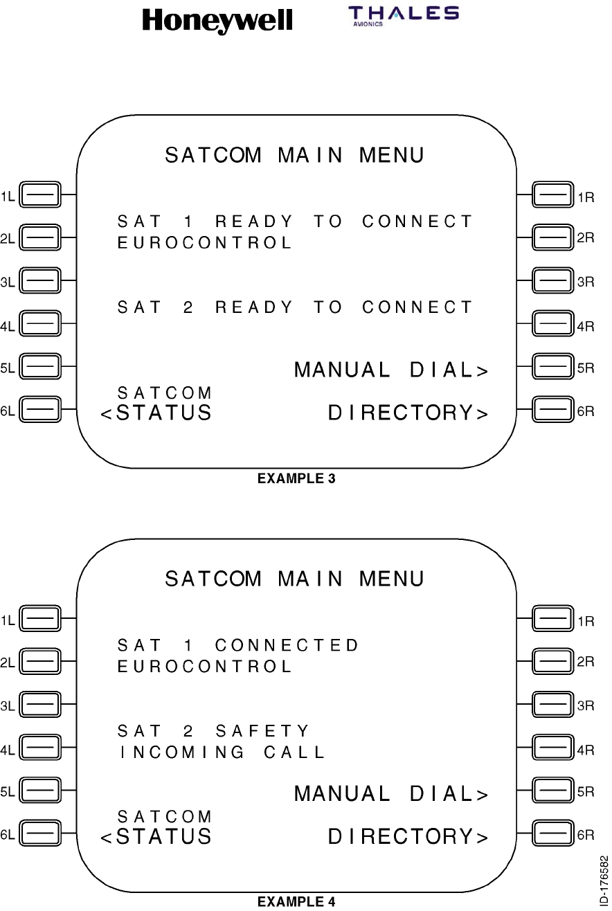
SYSTEM DESCRIPTION, INSTALLATION, AND MAINTENANCE MANUAL
MCS--4200/7200 Multi--Channel SATCOM System
23--20--35 15 Jul 2006
Honeywell International Inc. Do not copy without express permission of Honeywell.
Page 6--30
Figure 6-3 (Sheet 2, Airbus). SATCOM SCDU Main Menu Page

SYSTEM DESCRIPTION, INSTALLATION, AND MAINTENANCE MANUAL
MCS--4200/7200 Multi--Channel SATCOM System
23--20--35 15 Jul 2006
Honeywell International Inc. Do not copy without express permission of Honeywell.
Page 6--31
(2) SUBMENU or SATCOM STATUS Page
(a) Access to this page is from the SATCOM MAIN MENU page. The purpose of this
page is to display the current log-on state, to supply a way of entering and
displaying flight identifier, and to supply access to the SATCOM LOG-ON,
SATCOM CHANNEL STATUS, and SATCOM MAINTENANCE (or, if applicable,
DATA LOADER MENU) pages. When in a dual system, access to the DUAL
SYSTEM STATUS menu page is supplied. See Figure 6-4 for example pages.
(3) SATCOM MAINTENANCE Pages
(a) General
1An example SATCOM MAINTENANCE page for non-Airbus/Douglas CFDS
equipped aircraft is shown Figure 6-5.
2The SATCOM MAINTENANCE pages menu selection, subject to ORT item
iv (refer to SYSTEM OPERATION), is accessible from the SATCOM
SUBMENU page only on non-Airbus/Douglas CFDS equipped aircraft. In
Airbus and Douglas configurations, these pages are accessed through the
CFDS.
3The purpose of these pages are to display SATCOM maintenance data. In a
dual system, the maintenance data pertains to the system from which the
display pages are being supplied (SAT 1 or SAT 2).
4The display format and functionality for the SATCOM maintenance pages
(i.e., for the SAT--N, LAST LEG REPORT, PREVIOUS LEGS REPORT, LRU
IDENTIFICATION, LAST LEG CLASS 3 FAULTS, TEST, TROUBLESHOOT
DATA, GROUND TROUBLESHOOT DATA, GROUND REPORT, and
CONFIGURATION DATA pages) is the same as defined for the CFDS
interactive mode maintenance pages with the exception of the following:
•The RETURN> prompt is displayed on the right adjacent to the 6R key,
as opposed to the left.
•The SDU issues scratchpad message 1 (i.e., NOT ALLOWED) if any LS
key is pushed adjacent to a blank or display-only field.
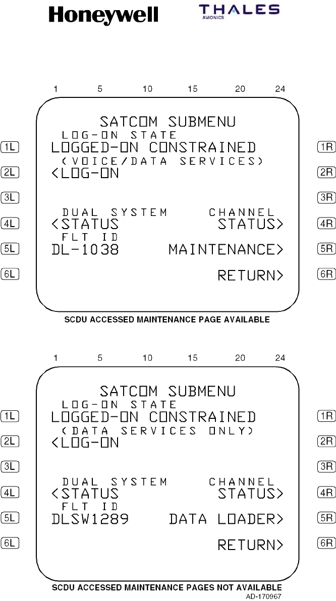
SYSTEM DESCRIPTION, INSTALLATION, AND MAINTENANCE MANUAL
MCS--4200/7200 Multi--Channel SATCOM System
23--20--35 15 Jul 2006
Honeywell International Inc. Do not copy without express permission of Honeywell.
Page 6--32
Figure 6-4 (Sheet 1, Boeing/Corporate). SATCOM SUBMENU Page
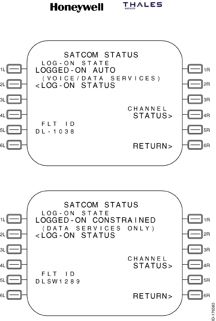
SYSTEM DESCRIPTION, INSTALLATION, AND MAINTENANCE MANUAL
MCS--4200/7200 Multi--Channel SATCOM System
23--20--35 15 Jul 2006
Honeywell International Inc. Do not copy without express permission of Honeywell.
Page 6--33
Figure 6-4 (Sheet 2, Airbus). SATCOM STATUS Page
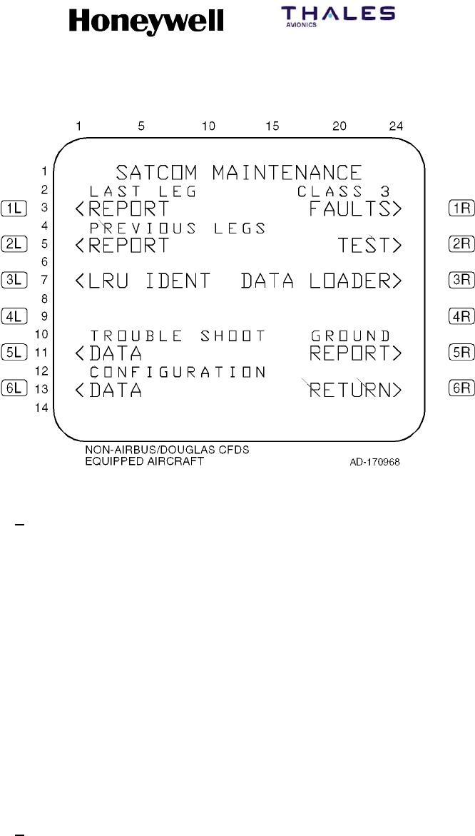
SYSTEM DESCRIPTION, INSTALLATION, AND MAINTENANCE MANUAL
MCS--4200/7200 Multi--Channel SATCOM System
23--20--35 15 Jul 2006
Honeywell International Inc. Do not copy without express permission of Honeywell.
Page 6--34
Figure 6-5. SATCOM MAINTENANCE Page
5Access to SATCOM maintenance displays are as follows:
•Push LS key 1L to show the Last Leg Report page (see Figure 6-10)
•Push LS key 2L to show the Previous Leg Report page (see Figure 6-11)
•Push LS key 3Lto show the LRU Identification page (see Figure 6-12)
•Push LS key 5L to show the Trouble Shooting Data page (see
Figure 6-13)
•Push LS key 6L to show the Configuration Data page (see Figure 6-8)
•Push LS key1R to show the Last Leg Class 3 Faults page (see
Figure 6-14)
•Push LS key 2R to show the Test page (see Figure 6-6)
•Push LS key 3R to show the Data Loader Menu page (see Figure 6-9)
•Push LS key 5R to show the Ground Report page (see Figure 6-15).
(b) TEST page
1If a system-wide functional test (i.e., PAST) is initiated from the SCDU
interface (i.e., by pushing the 2R key on the SATCOM MAINTENANCE
page), the first access of the SATCOM subsystem from an SCDU MAIN
MENU page after the POST/PAST Results Delay period causes the TEST
page to be shown with the status of the current failures. However, the TEST
page shows the TEST IN PROGRESS 60S message if this first access
occurs during the POST/PAST Results Delay period. If the SATCOM
subsystem is not accessed within 5 minutes of the completion of an
SCDU-initiated PAST, the page hierarchy is reset to its original structure as
shown in Figure 6-2.

SYSTEM DESCRIPTION, INSTALLATION, AND MAINTENANCE MANUAL
MCS--4200/7200 Multi--Channel SATCOM System
23--20--35 15 Jul 2006
Honeywell International Inc. Do not copy without express permission of Honeywell.
Page 6--35
2When the 2R key is pushed on the SATCOM MAINTENANCE (i.e., SAT--N)
page, the SDU initiates a PAST and the page display temporarily goes to the
TEST page where TEST IN PROGRESS 60S is displayed. However, the
SCDU eventually times out the SATCOM subsystem and takes back control
of the display. This is due to the fact that for SCDU-accessed maintenance
pages, the SDU interfaces directly with the SCDU (as opposed to going
through the CFDIU) and is unable to maintain proper bus activity (which the
CFDIU normally does) during initial execution of the PAST.
3To display the test results, the user must reselect the SATCOM system by
pushing the LS key adjacent to the <SAT prompt on the SCDU MAIN MENU
page, where the initial page shown is the TEST page. If the user does not
reselect the SATCOM system on the SCDU MAIN MENU page after 5
minutes of completion of PAST, the page hierarchy resets to its original
structure as shown in Figure 6-2.
4The TEST IN PROGRESS 60S message during the POST/PAST Results
Delay period is required to prevent the display of premature test results, i.e.,
to permit continuous monitoring sufficient time to add its contribution to the
POST/PAST results.
(4) TEST Menu Page
(a) General
1Access to this page is from the SAT--N (i.e., SATCOM MAINTENANCE)
page by pushing LS key 2R. The purpose of this page is to initiate a PAST,
to enable/disable a voice loopback on a selected (physical) channel, to
enable/disable a test of the cockpit voice call light for a selected (logical)
channel, and activation of the cockpit voice go-ahead chime test. See
Figure 6-6 for example pages.
(b) Data Fields
1Line 3
aThis line displays SELF-TEST beginning in column 1. The asterisk
prompt is not displayed if the aircraft is airborne.
bIf the LS key 1L is pushed when the SELF-TEST asterisk prompt is
shown, the system activates a PAST.
2Line 4
aThis line displays MP2ABCD VOICE LOOPBACK beginning in column
2. Pushing LS key 2l configures the SATCOM system to perform an
audio loopback test of flight deck channel 1.
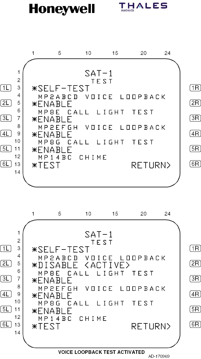
SYSTEM DESCRIPTION, INSTALLATION, AND MAINTENANCE MANUAL
MCS--4200/7200 Multi--Channel SATCOM System
23--20--35 15 Jul 2006
Honeywell International Inc. Do not copy without express permission of Honeywell.
Page 6--36
Figure 6-6 (Sheet 1). TEST Page
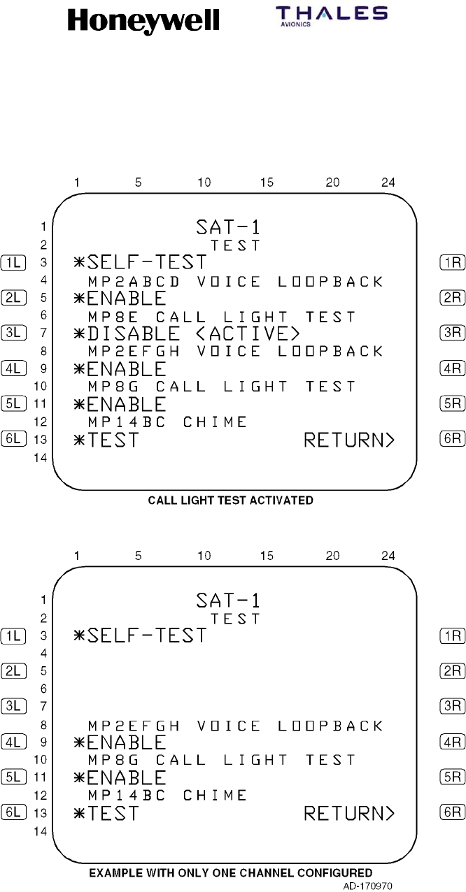
SYSTEM DESCRIPTION, INSTALLATION, AND MAINTENANCE MANUAL
MCS--4200/7200 Multi--Channel SATCOM System
23--20--35 15 Jul 2006
Honeywell International Inc. Do not copy without express permission of Honeywell.
Page 6--37
Figure 6-6 (Sheet 2). TEST Page

SYSTEM DESCRIPTION, INSTALLATION, AND MAINTENANCE MANUAL
MCS--4200/7200 Multi--Channel SATCOM System
23--20--35 15 Jul 2006
Honeywell International Inc. Do not copy without express permission of Honeywell.
Page 6--38
3Line 5
aThis line displays the message ENABLE beginning in column 1 when
the test is not active. The asterisk prompt is displayed and the test
allowed only if the log--on state is Standby. This line displays *DISABLE
<ACTIVE> beginning in column 1 when the test is active. If the log--on
state changes from Standby to any other state while the test is active,
the test is terminated. The commands on lines 4 and 5 are shown only if
the configuration straps indicate this channel is wired for headset use.
bPushing LS key 2L when the ENABLE asterisk prompt is shown causes
the voice channel selected to be activated into an analog loopback test
state. Pushing LS key 2L when the DISABLE prompt is shown causes
the voice loopback test state to be terminated.
4Line 6
aThis line displays MP8E CALL LIGHT TEST beginning in column 2.
Pushing LS key 3L initiates a lamp test of the flight deck channel 1 call
lamp.
5Line 7
aThis line displays *ENABLE beginning in column 1 when the test is not
active. The asterisk prompt is shown and the test allowed only if the
log--on state is Standby. This line displays *DISABLE <ACTIVE>
beginning in column 1 when the test is active. If the log--on state
changes from Standby to any other state while the test is active, the test
is terminated. The commands on lines 6 and 7 are shown only if the
configuration straps indicate this channel is wired for headset use.
bPushing LS key 3L when the ENABLE asterisk prompt is shown causes
the cockpit voice call light to be activated for a steady indication
(regardless of the state of configuration pin TP13C). Pushing LS key 3L
when the DISABLE prompt is displayed causes the cockpit voice call
light test to be terminated.
6LIne 8
aThis line displays MP2EFGH VOICE LOOPBACK beginning in column
2. Pushing LS key 4L configures the SATCOM system to perform an
audio loopback test of flight deck channel 2.
7Line 9
aThis line displays ENABLE beginning in column 1 when the test is not
active. The asterisk prompt is shown and the test allowed only if the
log--on state is Standby. This line displays *DISABLE <ACTIVE>
beginning in column 1 when the test is active. If the log--on state
changes from Standby to any other state while the test is active, the test
is terminated. The commands on lines 8 and 9 are displayed only if the
configuration straps indicate this channel is wired for headset use.

SYSTEM DESCRIPTION, INSTALLATION, AND MAINTENANCE MANUAL
MCS--4200/7200 Multi--Channel SATCOM System
23--20--35 15 Jul 2006
Honeywell International Inc. Do not copy without express permission of Honeywell.
Page 6--39
bPushing LS key 4L when the ENABLE asterisk prompt is displayed
causes the voice channel selected to be activated into an analog
loopback test state. Pushing LS key 4L when the DISABLE prompt is
displayed causes the voice loopback test state to be terminated.
8Line 10
aThis line displays MP8G CALL LIGHT TEST beginning in column 2.
Pushing LS key 5L initiates a lamp test of the flight deck channel 2 call
lamp.
9Line 11
aThis line displays *ENABLE beginning in column 1 when the test is not
active. The asterisk prompt is displayed and the test allowed only if the
log--on state is Standby. This line displays *DISABLE <ACTIVE>
beginning in column 1 when the test is active. If the log--on state
changes from Standby to any other state while the test is active, the test
is terminated. The commands on lines 10 and 11 are displayed only if
the configuration straps indicate this channel is wired for headset use.
bPushing LS key 5L when the ENABLE asterisk prompt is displayed
causes the cockpit voice call light to be activated for a steady indication
(regardless of the state of configuration pin TP13C). Pushing LS key 5L
when the DISABLE prompt is displayed causes the cockpit voice call
light test to be terminated.
10 Line 12
aThis line displays MP14BC CHIME beginning in column 2. Pushing LS
key 6L initiates the channel test.
11 Line 13
aThis line displays TEST beginning in column 1. The asterisk prompt is
displayed and the test allowed only if the log--on state is Standby.
bPushing LS key 6L when the asterisk prompt is displayed causes the
cockpit voice go-ahead chime to be activated for a single stroke.

SYSTEM DESCRIPTION, INSTALLATION, AND MAINTENANCE MANUAL
MCS--4200/7200 Multi--Channel SATCOM System
23--20--35 15 Jul 2006
Honeywell International Inc. Do not copy without express permission of Honeywell.
Page 6--40
(5) SATCOM SELF--TEST (PAST) Page
(a) General
1The purpose of this page is to initiate a PAST, to enable/disable a voice
loopback on a selected (physical) channel, to enable/disable a test of the
cockpit voice call light for a selected (logical) channel, and activation of the
cockpit voice go-ahead chime test. See Figure 6-7 for example pages.
(b) Data Fields
1Line 1
aThis line displays the title of the page, SAT--N, beginning in column 10,
where N represents 1 or 2 to indicate a single SDU (N = 1), SDU No. 1
(N = 1), or SDU No. 2 (N = 2) as determined by the settings of
configuration pins TP12E and TP12F.
bIf there are current failures to report after the execution of a PAST,
columns 20 thru 24 display p/t in small font, where p represents the
current displayed page, and t represents the total number of pages
needed to show the current failures. The display of the slash is always
in column 22, with p right-justified to the slash and t left-justified to the
slash.
2Line 3
aThis line displays headers ATA beginning in column 1 and CLASS
beginning in column 20 if there are current failures to report after
execution of a PAST. This line is blank if there are no failures to report.
bIn addition to the above, for CFDS type none, the header ATA is not
displayed (CLASS is still displayed as specified).
3Line 5
aThis line displays the message TEST IN PROGRESS 60S beginning in
column 3 within one second of a PAST being initiated on the SAT--N
(i.e., SATCOM MAINTENANCE) page, and then throughout the duration
of PAST. If there are no current failures to report at the conclusion of the
PAST (including the POST/PAST results delay period), the message
TEST OK is displayed. If there are current failures to report at the
conclusion of the PAST (including the POST/PAST results delay period),
refer to paragraph 4 for line requirements.
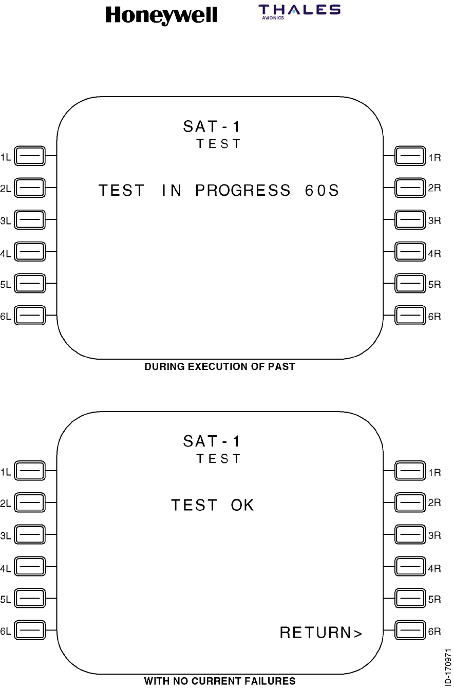
SYSTEM DESCRIPTION, INSTALLATION, AND MAINTENANCE MANUAL
MCS--4200/7200 Multi--Channel SATCOM System
23--20--35 15 Jul 2006
Honeywell International Inc. Do not copy without express permission of Honeywell.
Page 6--41
Figure 6-7 (Sheet 1). SATCOM SELF--TEST Page
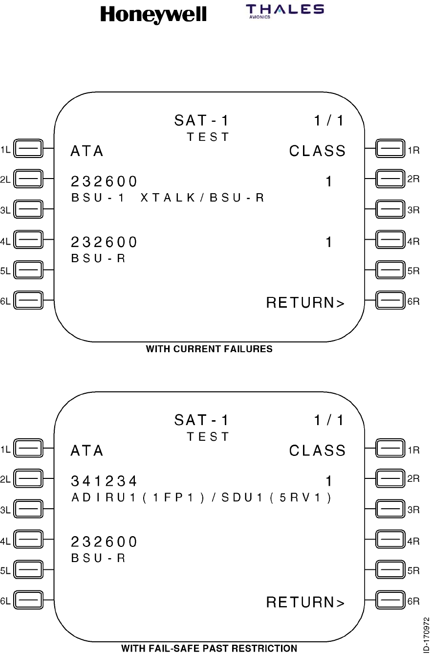
SYSTEM DESCRIPTION, INSTALLATION, AND MAINTENANCE MANUAL
MCS--4200/7200 Multi--Channel SATCOM System
23--20--35 15 Jul 2006
Honeywell International Inc. Do not copy without express permission of Honeywell.
Page 6--42
Figure 6-7 (Sheet 2). SATCOM SELF--TEST Page

SYSTEM DESCRIPTION, INSTALLATION, AND MAINTENANCE MANUAL
MCS--4200/7200 Multi--Channel SATCOM System
23--20--35 15 Jul 2006
Honeywell International Inc. Do not copy without express permission of Honeywell.
Page 6--43
4Other Information
aThe SELF--TEST page lists two failures per page if failures are detected
during the PAST(self--test). These two sets of lines (lines 5, 6, and 7
and lines 9, 10, and 11) display Level 1 diagnosed current failures.
Failures are shown in chronological order (i.e., the most recent detected
failure last) with no more than two failures displayed per page.
bThe number of TEST pages depends on the number of current failures
to report (up to a maximum of 99 pages). When there is an odd number
of current failures to report, the odd failure is displayed on a separate
page in lines 5, 6, and 7, and lines 9, 10, and 11 are blank. If there are
no failures to report, lines 5, 6, 7, 9, 10, and 11 are blank except as
noted in paragraph 3.
cLine 5 and, if applicable, line 9 display the ATA number beginning in
column 1 and the class number beginning in column 23. The ATA
number is displayed as aaaaaa, where aaaaaa represents the ATA
reference number of the reported failure as specified in paragraph 3.E.
for each type of CFDS. For CFDS type none, no ATA number is
displayed. The class number is displayed as c, where c represents the
class (1, 2, or 3) of the failure.
dLines 6 and 7 and, if applicable, lines 10 and 11 display a text message,
as specified in paragraph 3.E. for each CFDS type, for the reported
failure beginning in column 1.
(6) CONFIGURATION DATA Pages
(a) General
1Access to these pages is from the SAT--N (i.e., SATCOM MAINTENANCE)
page. The purpose of these pages is to display the status of SATCOM
configuration input parameters. See Figure 6-8 for example pages.
(b) CONFIGURATION DATA Page 1 (Figure 6-8, sheet 1):
1Data Fields
aLine 3
(1) This line displays the ICAO address of eight octal characters, as
determined by discrete inputs from the ICAO address straps. This
display is not derived from any ARINC 429 version of the ICAO
address.
bLine 5
(1) This line displays CONFIG as determined by the setting of the
system configuration pins, followed by (HEX). The configuration pin
settings are mapped into hexadecimal digits as shown in
Table 6-10. In the figure, digits 0 thru 9 correlate to hexadecimal
digits 0 thru 9 in the table.
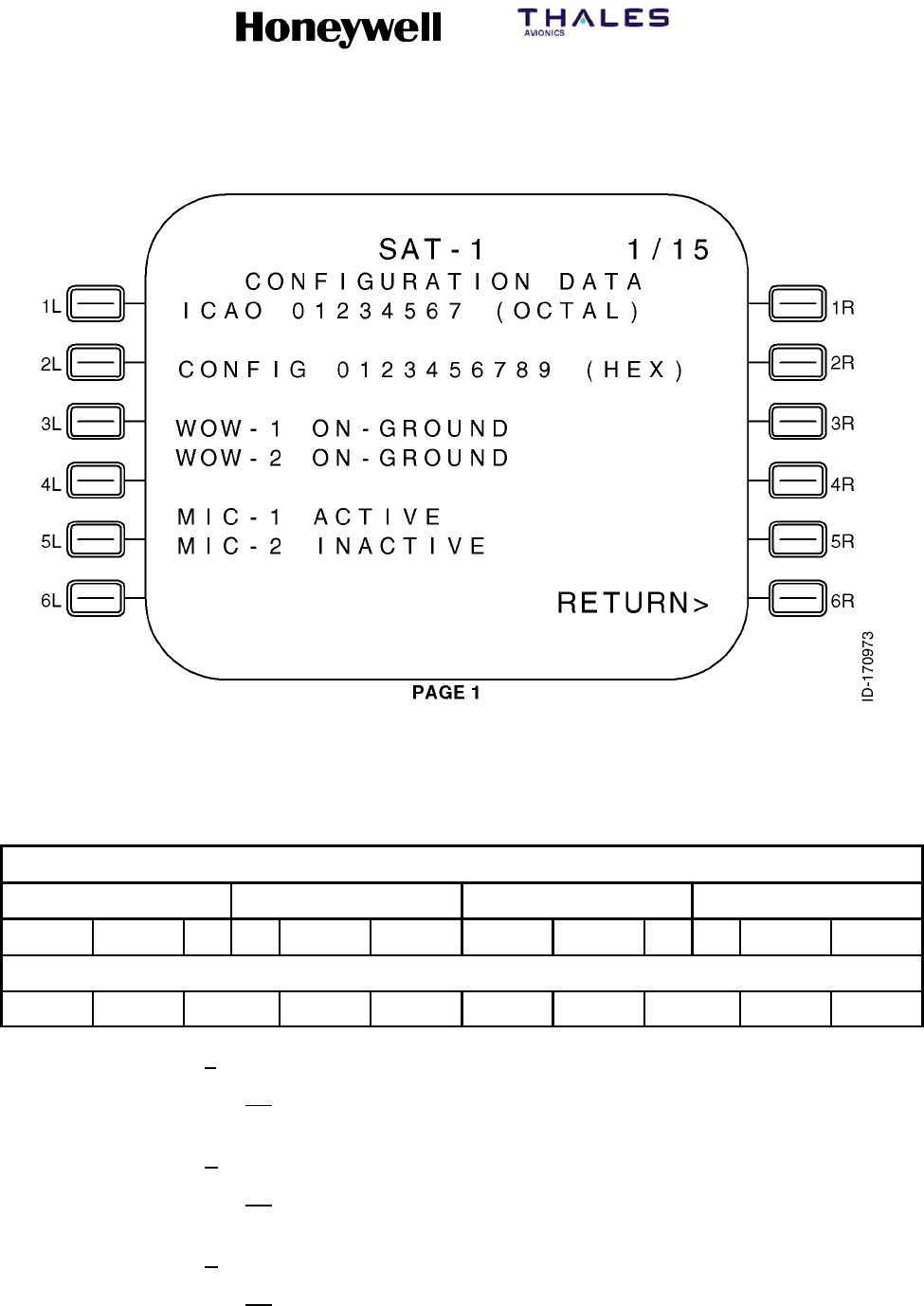
SYSTEM DESCRIPTION, INSTALLATION, AND MAINTENANCE MANUAL
MCS--4200/7200 Multi--Channel SATCOM System
23--20--35 15 Jul 2006
Honeywell International Inc. Do not copy without express permission of Honeywell.
Page 6--44
Figure 6-8 (Sheet 1). Configuration Data
Table 6-10. System Configuration Pin Mapping
Configuration Pins
TP10 TP11 TP12 TP13
ABCD EFGH JK AB CDEF GHJK ABCD EFGH JK AB CDEF GHJK
Hex Digits
0 1 2 3 4 5 6 7 8 9
cLine 7
(1) This line displays the WOW--1 status of SDU weight-on-wheels
discrete input No. 1 as IN-AIR/NOT WIRED or ON-GROUND.
dLine 8
(1) This line displays the WOW--2 status of the SDU weight-on-wheels
discrete input No. 2 as IN-AIR/NOT WIRED or ON-GROUND.
eLine 10
(1) This line displays the MIC--1 status of the SDU cockpit voice
microphone On discrete input No. 1 as ACTIVE or INACTIVE.

SYSTEM DESCRIPTION, INSTALLATION, AND MAINTENANCE MANUAL
MCS--4200/7200 Multi--Channel SATCOM System
23--20--35 15 Jul 2006
Honeywell International Inc. Do not copy without express permission of Honeywell.
Page 6--45
fLine 11
(1) This line displays the MIC--2 status of the SDU cockpit voice
microphone On discrete input No. 2 as ACTIVE or INACTIVE.
(c) CONFIGURATION DATA Page 2 (Figure 6-8, sheet 2):
1Data Fields
aLine 3
(1) This line displays the CHIME RESET status of the SDU cockpit
voice go-ahead chime signal reset discrete input as ACTIVE or
INACTIVE.
bLine 5
(1) This line displays the DUAL SYS SELECT status of the SDU dual
system select discrete input as ACTIVE or INACT.
cLine 6
(1) This line displays the DUAL SYS DISABLE status of the SDU dual
system disable discrete input as ACTIVE or INACT.
dLine 8
(1) This line displays IRS SOURCE as determined by which IRS input
bus the SDU is using. A dash is displayed for the IRS source if a
429 source of IRS is not connected to the SDU.
eLine 10
(1) This line displays the PLACE/END CALL 1 status of the SDU
cockpit voice place/end call 1 discrete input as ACTIVE or INACT.
fLine 11
(1) This line displays the PLACE/END CALL 2 status of the SDU
cockpit voice place/end call 2 discrete input as ACTIVE or INACT.
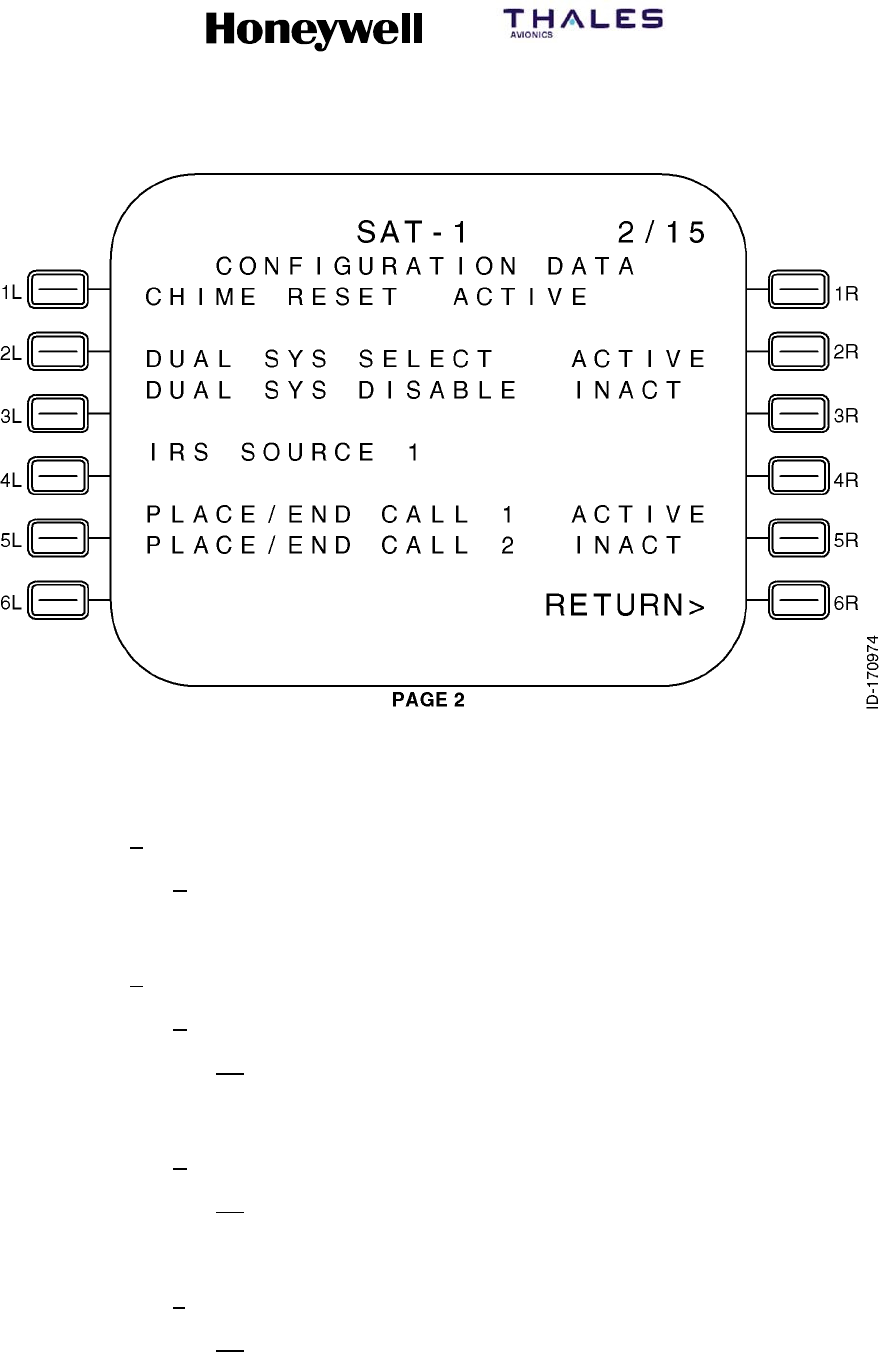
SYSTEM DESCRIPTION, INSTALLATION, AND MAINTENANCE MANUAL
MCS--4200/7200 Multi--Channel SATCOM System
23--20--35 15 Jul 2006
Honeywell International Inc. Do not copy without express permission of Honeywell.
Page 6--46
Figure 6-8 (Sheet 2). Configuration Data
(d) CONFIGURATION DATA Page 3 (Figure 6-8, sheet 3):
1General
aFor CONFIGURATION DATA pages 3 thru 10, the strap setting value 0
or 1 in parentheses is as follows: 1= open circuit; and 0 = tied to
common.
2Data Fields
aLine 4
(1) This line displays A(0) ICAO ADRS AVAIL or A(1) ICAO ADRS NOT
AVAIL left-justified as determined by the state of system
configuration pin TP10A.
bLine 6
(1) This line displays B(0) FMC1 CONNECTED or B(1) FMC1 NOT
CONNECTED left-justified as determined by the state of system
configuration pin TP10B.
cLine 8
(1) This line displays C(0) FMC2 CONNECTED or C(1) FMC2 NOT
CONNECTED left-justified as determined by the state of system
configuration pin TP10C.
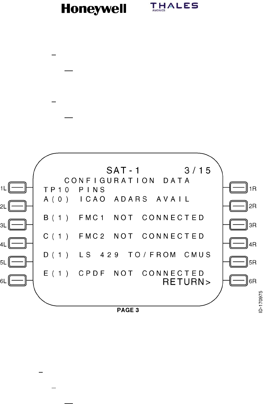
SYSTEM DESCRIPTION, INSTALLATION, AND MAINTENANCE MANUAL
MCS--4200/7200 Multi--Channel SATCOM System
23--20--35 15 Jul 2006
Honeywell International Inc. Do not copy without express permission of Honeywell.
Page 6--47
dLine 10
(1) This line displays D(0) HS 429 TO/FROM CMUS or D(1) LS 429
TO/FROM CMUS left-justified as determined by the state of system
configuration pin TP10D.
eLine 12
(1) This line displays E(0) CPDF CONNECTED or E(1) CPDF NOT
CONNECTED left-justified as determined by the state of system
configuration pin TP10E.
Figure 6-8 (Sheet 3). Configuration Data
(e) CONFIGURATION DATA Page 4 (Figure 6-8, sheet 4):
1Data Fields
aLine 4
(1) This line displays F(0) HS 429 ICAO ADRS or F(1) LS 429 ICAO
ADRS left-justified as determined by the state of system
configuration pin TP10F.
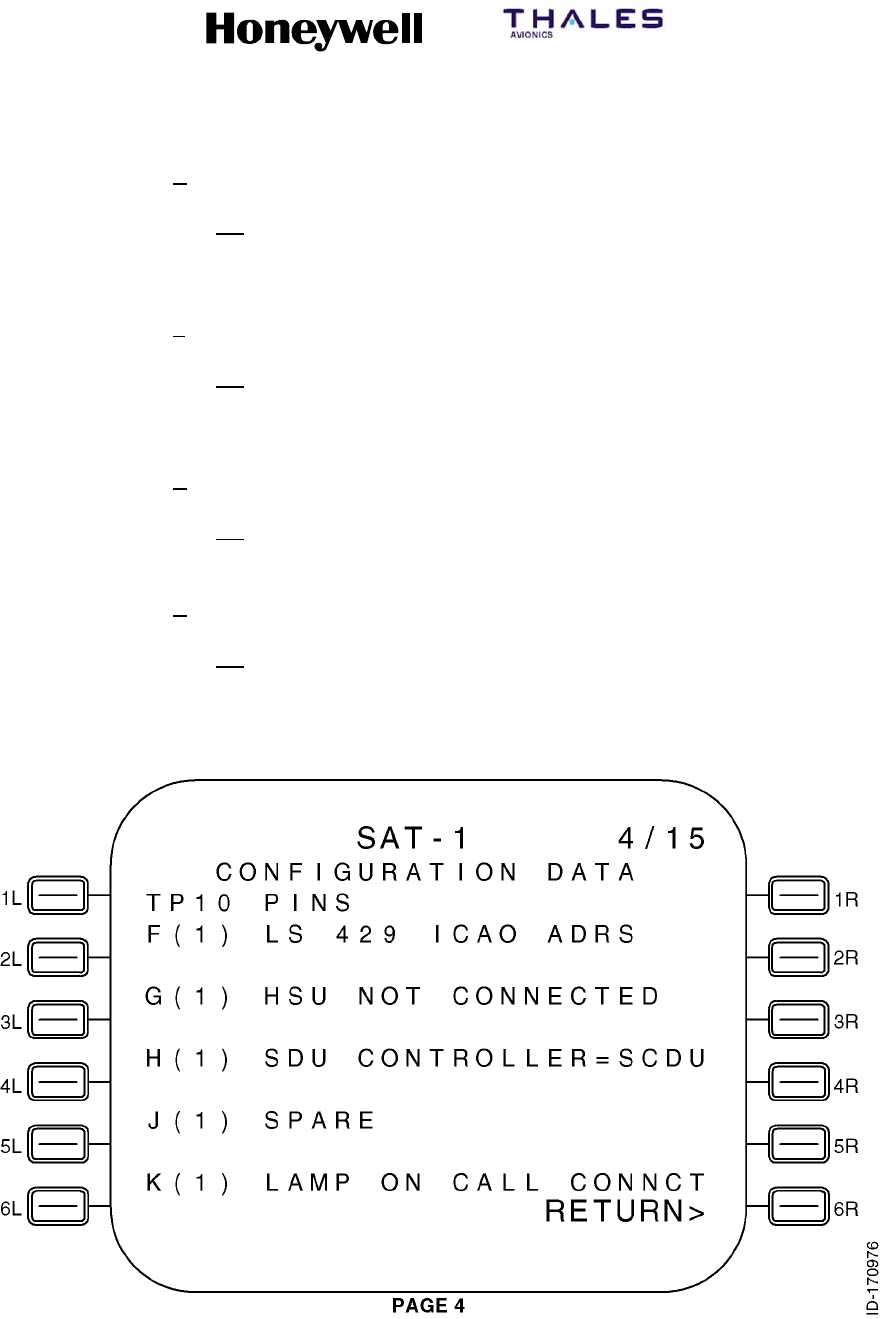
SYSTEM DESCRIPTION, INSTALLATION, AND MAINTENANCE MANUAL
MCS--4200/7200 Multi--Channel SATCOM System
23--20--35 15 Jul 2006
Honeywell International Inc. Do not copy without express permission of Honeywell.
Page 6--48
bLine 6
(1) This line displays G(0) HSU CONNECTED or G(1) HSU NOT
CONNECTED left-justified as determined by the state of system
configuration pin TP10G.
cLine 8
(1) This line displays H(0) SDU CONTROLLER=WSC or H(1) SDU
CONTROLLER=SCDU left-justified as determined by the state of
system configuration pin TP10H.
dLine 10
(1) This line displays J(0) SPARE or J(1) SPARE left-justified as
determined by the state of system configuration pin TP10J.
eLine 12
(1) This line displays K(0) LAMP ON CALL INIT or K(1) LAMP ON
CALL CONNCT left-justified as determined by the state of system
configuration pin TP10K.
Figure 6-8 (Sheet 4). Configuration Data

SYSTEM DESCRIPTION, INSTALLATION, AND MAINTENANCE MANUAL
MCS--4200/7200 Multi--Channel SATCOM System
23--20--35 15 Jul 2006
Honeywell International Inc. Do not copy without express permission of Honeywell.
Page 6--49
(f) CONFIGURATION DATA Page 5 (Figure 6-8, sheet 5):
1Data Fields
aLine 4
(1) This line displays A(0) PARITY: GOOD, A(1) PARITY: GOOD, A(0)
PARITY: BAD, or A(1) PARITY: BAD left-justified as determined by
the state of system configuration pin TP11A and the result of the
parity validation test.
bLine 6
(1) This line displays B(0) CCS INSTALLED or B(1) CCS NOT
INSTALLED left-justified as determined by the state of system
configuration pin TP11B.
cLine 8
(1) This line displays C(0) PRI IRS INSTALLED or C(1) PRI IRS NOT
INSTLLD left-justified as determined by the state of system
configuration pin TP11C.
dLine 10
(1) This line displays D(0) SEC IRS INSTALLED or D(1) SEC IRS NOT
INSTLLD left-justified as determined by the state of system
configuration pin TP11D.
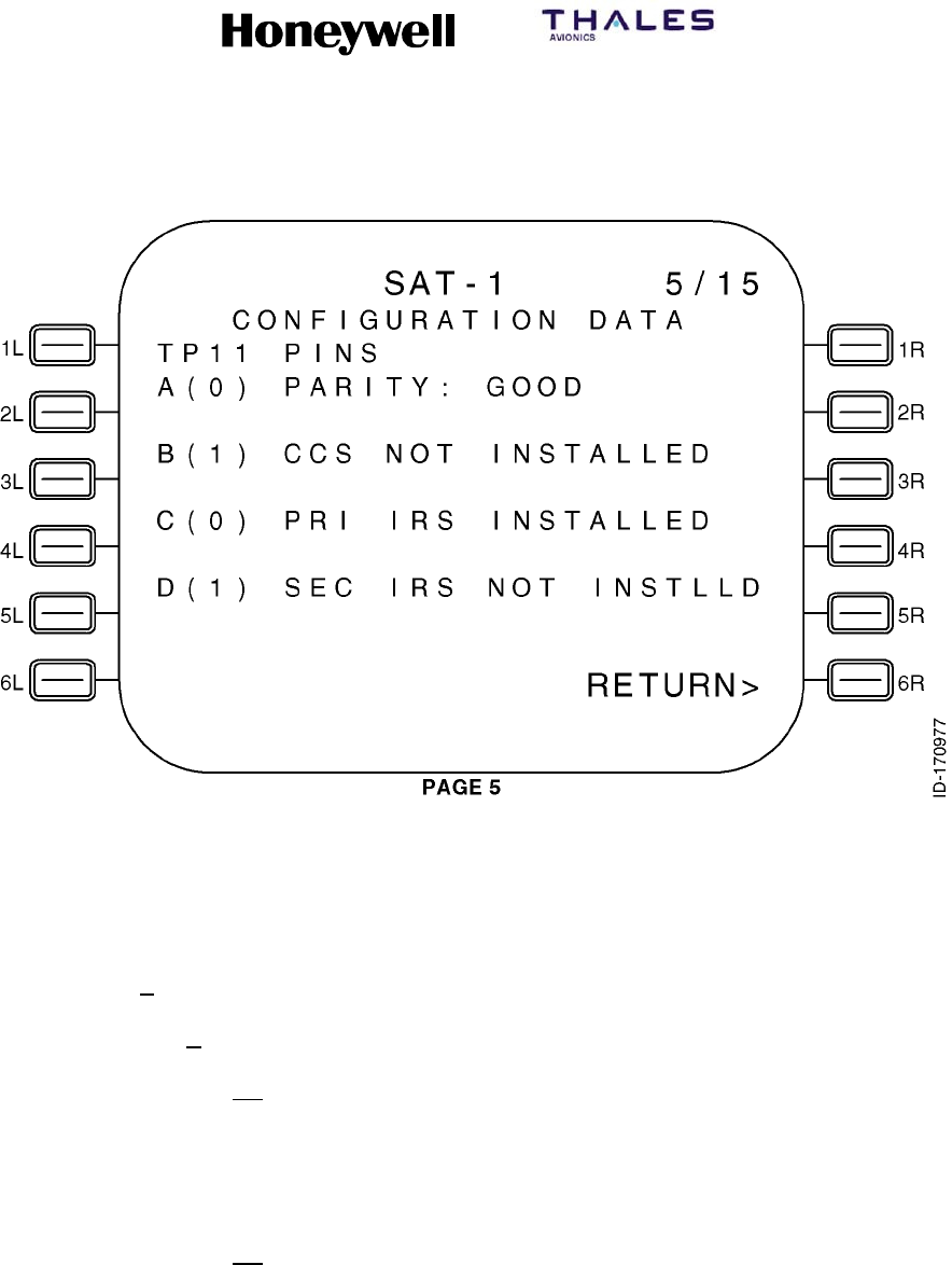
SYSTEM DESCRIPTION, INSTALLATION, AND MAINTENANCE MANUAL
MCS--4200/7200 Multi--Channel SATCOM System
23--20--35 15 Jul 2006
Honeywell International Inc. Do not copy without express permission of Honeywell.
Page 6--50
Figure 6-8 (Sheet 5). Configuration Data
(g) CONFIGURATION DATA Page 6 (Figure 6-8, sheet 6):
1Data Fields
aLines 4 thru 9
(1) These lines display X(0)* or X(1)* left-justified as shown in the
figure, where X represents E, F, G, H, J, and K, respectively. X(0)*
or X(1)* is determined by the states of system configuration pins
TP11E, TP11F, TP11G, TP11H, TP11J, and TP11K. Asterisks are
displayed in column 5 to indicate these pins are a coded group.
(2) Beginning in column 6, textual messages are displayed (refer to
Table 6-11) in lines 4 thru 9 (as needed), where an x indicates the
message(s) to be displayed based on the state of system
configuration pins TP11E, TP11F, TP11G, TP11H, TP11J, and
TP11K.
SYSTEM DESCRIPTION, INSTALLATION, AND MAINTENANCE MANUAL
MCS--4200/7200 Multi--Channel SATCOM System
23--20--35 15 Jul 2006
Honeywell International Inc. Do not copy without express permission of Honeywell.
Page 6--51
Table 6-11. Textual Message Display (Page 6 -- Lines 4 thru 9)
System Configuration Pin
System Configuration Pin Settings
(1 = open circuit / 0 = tied to common)
TP11E 101011 All Other Pin Combinations
TP11F 110011
TP11G 111111
TP11H 111100
TP11J 111110
TP11K 111110
Textual Message Textual Messages To Display Based On System Configuration Pin
Settings
LO GAIN ANT+DLNA X X X
HPA--LO GAIN X X X
HI GAIN ANT+BSU--T/L XXXX
HI GAIN ANT+BSU--R X X
HPA--HI GAIN XXXX
HI POWER RELAY X X
HPA--IGA X
ERROR/UNDEFINED X
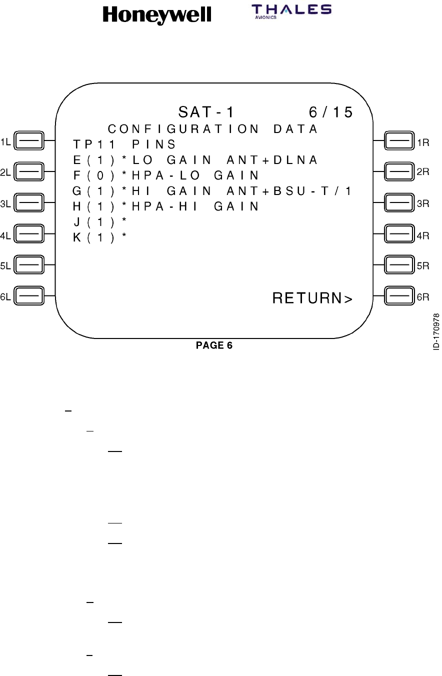
SYSTEM DESCRIPTION, INSTALLATION, AND MAINTENANCE MANUAL
MCS--4200/7200 Multi--Channel SATCOM System
23--20--35 15 Jul 2006
Honeywell International Inc. Do not copy without express permission of Honeywell.
Page 6--52
Figure 6-8 (Sheet 6). Configuration Data
(h) CONFIGURATION DATA Page 7 (Figure 6-8, sheet 7):
1Data Fields
aLines 4 thru 6
(1) These lines display X(0)* or X(1)* left-justified as shown in the
figure, where X represents A, B and C, respectively. X(0)* or X(1)*
are determined by the state of system configuration pins TP12A,
TP12B, and TP12C. Asterisks are displayed in column 5 to indicate
these pins are a coded group.
(2) CFDS/CMC TYPE = is displayed in line 4 beginning in column 6.
(3) Beginning in column 6, a textual message is displayed according to
Table 6-12, where an x indicates the message to be displayed,
based on the state of system configuration pins TP12A, TP12B and
TP12C.
bLine 10
(1) This line displays D(0) RESERVED or D(1) RESERVED left-justified
as determined by the state of system configuration pin TP12D.
cLine 12
(1) This line displays E(0) OTHER SDU INSTALLED or E(1) OTHER
SDU NOT INSTD left-justified as determined by the state of system
configuration pin TP12E.
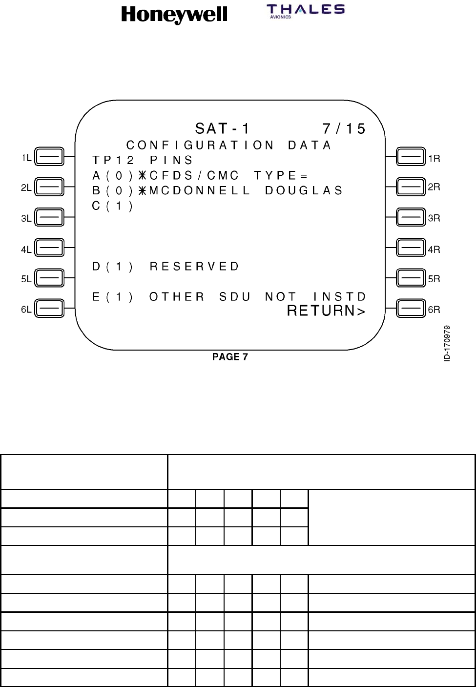
SYSTEM DESCRIPTION, INSTALLATION, AND MAINTENANCE MANUAL
MCS--4200/7200 Multi--Channel SATCOM System
23--20--35 15 Jul 2006
Honeywell International Inc. Do not copy without express permission of Honeywell.
Page 6--53
Figure 6-8 (Sheet 7). Configuration Data
Table 6-12. Textual Message Display (Page 7 -- Lines 4, 5, and 6)
System Configuration Pin
System Configuration Pin Settings
(1 = open circuit / 0 = tied to common)
TP12A 00110 All Other Pin Combinations
TP12B 01011
TP12C 10011
Textual Message Textual Messages To Display Based On System Configuration Pin
Settings
MCDONNELL--DOUGLAS X
AIRBUS X
BOEING X
NOT INSTALLED X
ERROR/UNDEFINED X
CAIMS X

SYSTEM DESCRIPTION, INSTALLATION, AND MAINTENANCE MANUAL
MCS--4200/7200 Multi--Channel SATCOM System
23--20--35 15 Jul 2006
Honeywell International Inc. Do not copy without express permission of Honeywell.
Page 6--54
(i) CONFIGURATION DATA Page 8 (Figure 6-8, sheet 8):
1Data Fields
aLine 4
(1) This line displays F(0) THIS IS SDU2 or F(1) THIS IS SDU1
left-justified as determined by the state of system configuration pin
TP12F.
bLine 6 --
(1) This line displays G(0) CMU1 INSTALLED or G(1) CMU1 NOT
INSTALLED left-justified as determined by the state of system
configuration pin TP12G.
cLine 8
(1) This line displays H(0) CMU2 INSTALLED or H(1) CMU2 NOT
INSTALLED left-justified as determined by the state of system
configuration pin TP12H.
dLine 10
(1) This line displays J(0) SCDU1 INSTALLED or J(1) SCDU1 NOT
INSTALLED left-justified as determined by the state of system
configuration pin TP12J.
eLine 12
(1) This line displays K(0) SCDU2 INSTALLED or K(1) SCDU2 NOT
INSTALLED left-justified as determined by the state of system
configuration pin TP12K.

SYSTEM DESCRIPTION, INSTALLATION, AND MAINTENANCE MANUAL
MCS--4200/7200 Multi--Channel SATCOM System
23--20--35 15 Jul 2006
Honeywell International Inc. Do not copy without express permission of Honeywell.
Page 6--55
Figure 6-8 (Sheet 8). Configuration Data
(j) CONFIGURATION DATA Page 9 (Figure 6-8, sheet 9):
1Data Fields
aLine 4
(1) This line displays A(0) NO HSET PRI 4 CALLS or A(1) HSET PRI 4
CALLS OK left-justified as determined by the state of system
configuration pin TP13A.
bLine 6
(1) This line displays B(0) LS 429 TO SCDUS or B(1) HS 429 TO
SCDUS left-justified as determined by the state of system
configuration pin TP13B.
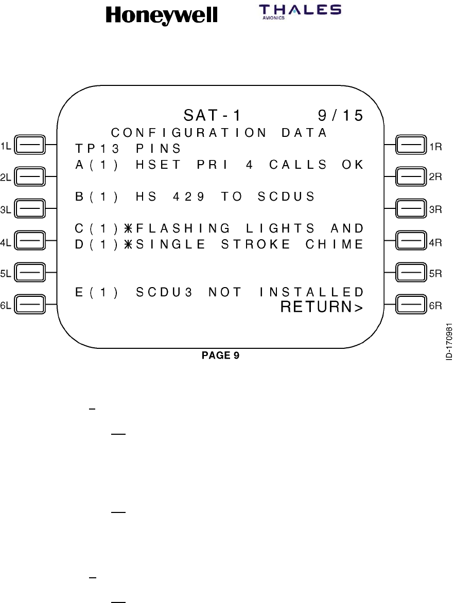
SYSTEM DESCRIPTION, INSTALLATION, AND MAINTENANCE MANUAL
MCS--4200/7200 Multi--Channel SATCOM System
23--20--35 15 Jul 2006
Honeywell International Inc. Do not copy without express permission of Honeywell.
Page 6--56
Figure 6-8 (Sheet 9). Configuration Data
cLines 8 and 9
(1) These lines display X(0)* or X(1)* left-justified as shown in the
figure, where X represents C and D, respectively. X(0)* or X(1)* are
determined by the state of system configuration pins TP13C and
TP13D. Asterisks are displayed in column 5 to indicate these pins
are a coded group.
(2) Beginning in column 6, a textual message is shown in line 8 and
according to Table 6-13, where an x indicates the message to be
displayed, based on the state of system configuration pins TP13C
and TP13D.
dLine 12
(1) This line displays E(0) SCDU3 INSTALLED or E(1) SCDU3 NOT
INSTALLED left-justified as determined by the state of system
configuration pin TP13E.
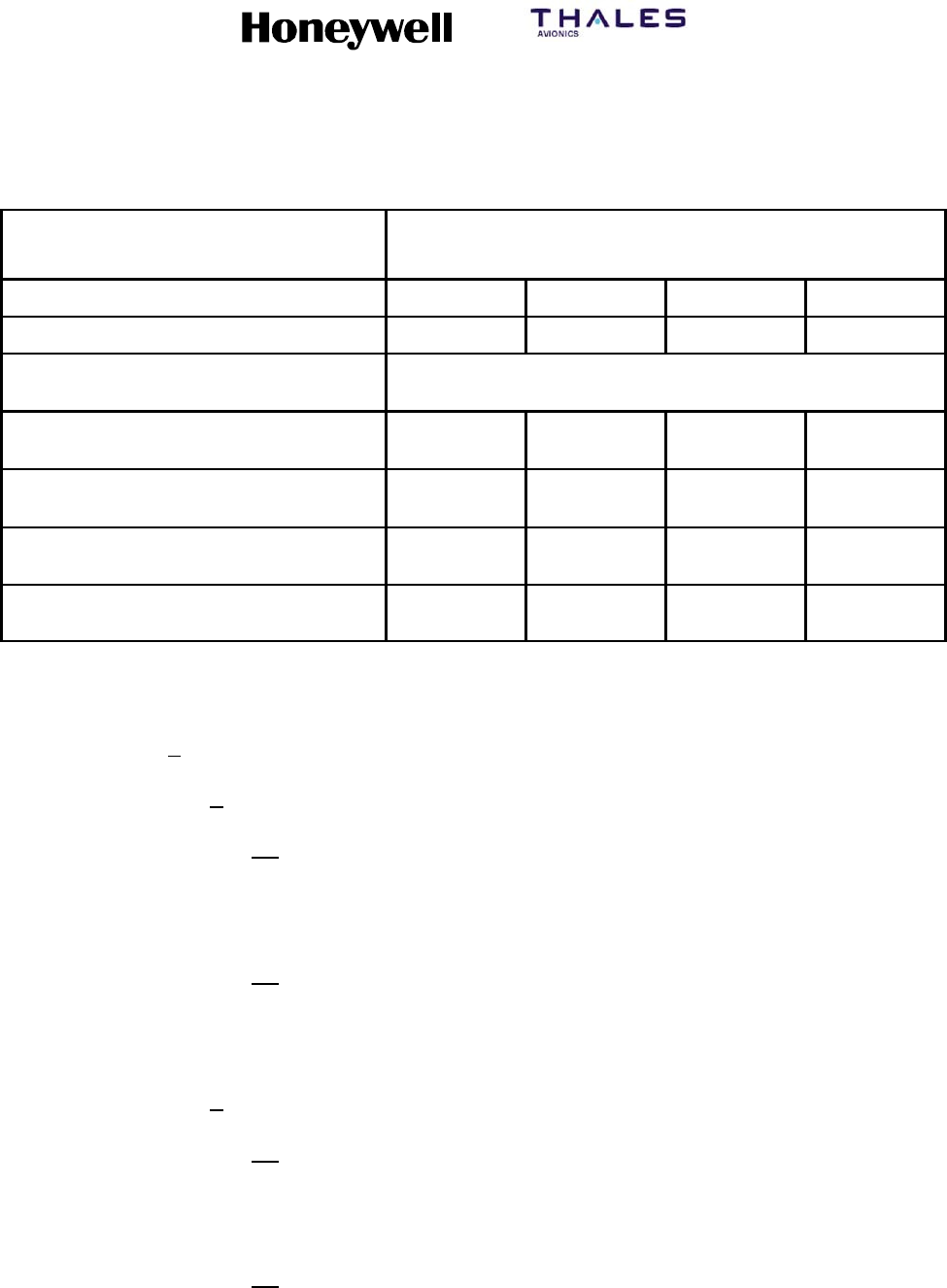
SYSTEM DESCRIPTION, INSTALLATION, AND MAINTENANCE MANUAL
MCS--4200/7200 Multi--Channel SATCOM System
23--20--35 15 Jul 2006
Honeywell International Inc. Do not copy without express permission of Honeywell.
Page 6--57
Table 6-13. Textual Message Display (Page 9 -- Lines 8 and 9)
System Configuration Pin
System Configuration Pin Settings
(1 = open circuit / 0 = tied to common)
TP13C 0011
TP13D 0101
Textual Message Textual Messages to Display Based on System Configuration
Pin Settings
LIGHTS AND CHIME
UNDEFINED
(Line 8)
(Line 9)
X
STEADY LIGHTS AND
MULTISTROKE CHIME
(Line 8)
(Line 9)
X
FLASHING LIGHTS AND
SINGLE STROKE CHIME
(Line 8)
(Line 9)
X
STEADY LIGHTS AND
SINGLE STROKE CHIME
(Line 8)
(Line 9)
X
(k) CONFIGURATION DATA Page 10 (Figure 6-8, sheet 10):
1Data Fields
aLines 4 and 5
(1) These lines display X(0)* or X(1)* left-justified as shown in the
figure, where X represents F and G, respectively. X(0)* or X(1)* are
determined by the state of system configuration pins TP13F and
TP13G.
(2) Beginning in column 6, a textual message is displayed in lines 4
and 5 according to Table 6-14, where an x indicates the message to
be displayed based on the state of system configuration pins
TP13F and TP13G.
bLines 8 and 9
(1) These lines display X(0)* or X(1)* left-justified, where X represents
H and J, respectively. X(0)* or X(1)* are determined by the state of
system configuration pins TP13H and TP13J. Asterisks are
displayed in column 5 to indicate these pins are a coded group.
(2) Beginning in column 6, a textual message is displayed in lines 8
and 9 according to Table 6-15, where an x indicates the message to
be displayed based on the state of system configuration pins
TP13H and TP13J.
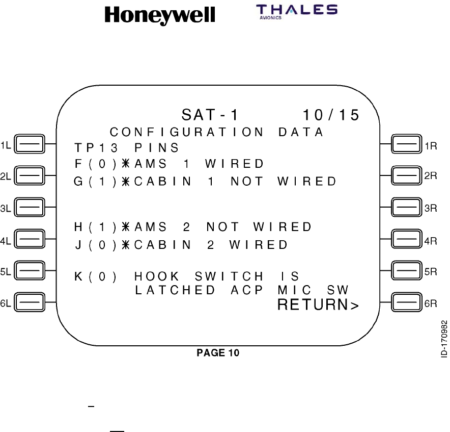
SYSTEM DESCRIPTION, INSTALLATION, AND MAINTENANCE MANUAL
MCS--4200/7200 Multi--Channel SATCOM System
23--20--35 15 Jul 2006
Honeywell International Inc. Do not copy without express permission of Honeywell.
Page 6--58
Figure 6-8 (Sheet 10). Configuration Data
cLines 11 and 12
(1) Line 11 displays K(0) HOOK SWITCH IS left-justified and line 12
displays LATCHED ACP MIC SW beginning in column 6; or line 11
displays K(1) HOOK SWITCH IS left-justified and line 12 displays
SWITCHED PTT/SCDU beginning in column 6, as determined by
the state of system configuration pin TP13K.
SYSTEM DESCRIPTION, INSTALLATION, AND MAINTENANCE MANUAL
MCS--4200/7200 Multi--Channel SATCOM System
23--20--35 15 Jul 2006
Honeywell International Inc. Do not copy without express permission of Honeywell.
Page 6--59
Table 6-14. Textual Message Display (Page 10 -- Lines 4 and 5)
System Configuration Pin
System Configuration Pin Settings
(1 = open circuit / 0 = tied to common)
TP13F 0011
TP13G 0101
Textual Message Textual Messages to Display Based on System Configuration
Pin Settings
AMS 1 WIRED
CABIN 1 WIRED
(Line 4)
(Line 5)
X
AMS 1 WIRED
CABIN 1 NOT WIRED
(Line 4)
(Line 5)
X
AMS 1 NOT WIRED
CABIN 1 WIRED
(Line 4)
(Line 5)
X
AMS 1 NOT WIRED
CABIN 1 NOT WIRED
(Line 4)
(Line 5)
X
Table 6-15. Textual Message Display (Page 10 -- Lines 8 and 9)
System Configuration Pin
System Configuration Pin Settings
(1 = open circuit / 0 = tied to common)
TP13H 0011
TP13J 0101
Textual Message Textual Messages to Display Based on System Configuration
Pin Settings
AMS 2 WIRED
CABIN 2 WIRED
(Line 8)
(Line 9)
X
AMS 2 WIRED
CABIN 2 NOT WIRED
(Line 8)
(Line 9)
X
AMS 2 NOT WIRED
CABIN 2 WIRED
(Line 8)
(Line 9)
X
AMS 2 NOT WIRED
CABIN 2 NOT WIRED
(Line 8)
(Line 9)
X
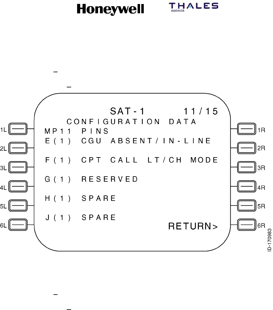
SYSTEM DESCRIPTION, INSTALLATION, AND MAINTENANCE MANUAL
MCS--4200/7200 Multi--Channel SATCOM System
23--20--35 15 Jul 2006
Honeywell International Inc. Do not copy without express permission of Honeywell.
Page 6--60
(l) CONFIGURATION DATA Page 11 (Figure 6-8, Sheet 11):
1General
aPage 11 of the CONFIGURATION DATA page is shown below.
Figure 6-8 (Sheet 11). Configuration Data
(m) CONFIGURATION DATA Page 12 (Figure 6-8, Sheet 12):
1General
aPage 12 of the CONFIGURATION DATA page is shown below.
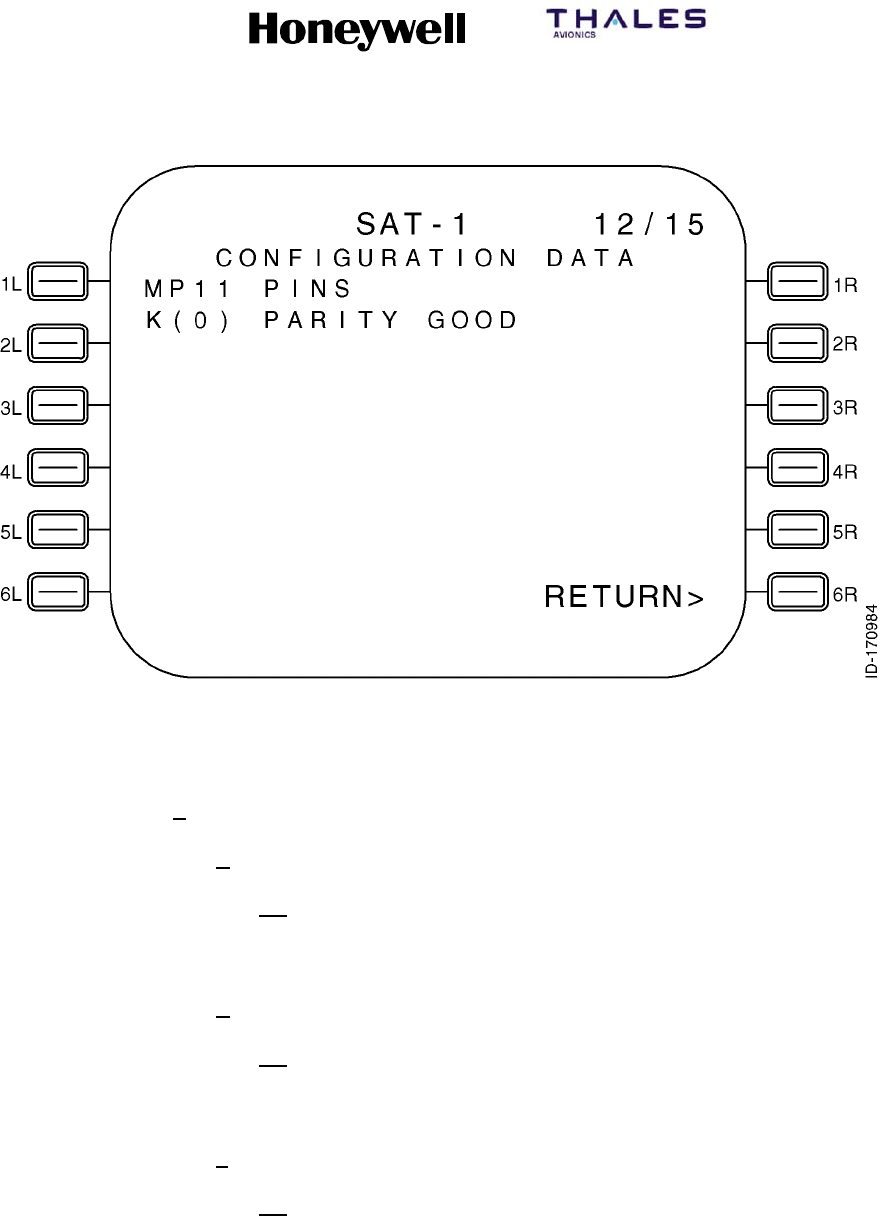
SYSTEM DESCRIPTION, INSTALLATION, AND MAINTENANCE MANUAL
MCS--4200/7200 Multi--Channel SATCOM System
23--20--35 15 Jul 2006
Honeywell International Inc. Do not copy without express permission of Honeywell.
Page 6--61
Figure 6-8 (Sheet 12). Configuration Data
(n) CONFIGURATION DATA Page 13 (Figure 6-8, Sheet 13):
1Data Fields
aLine 3
(1) This line displays the CALL LAMP 1 status of the SDU Cockpit
Voice-Call Lamp Discrete Output as ACTIVE or INACT as
appropriate.
bLine 4
(1) This line displays the CALL LAMP 2 status of the SDU Cockpit
Voice-Call Lamp Discrete Output as ACTIVE or INACT as
appropriate.
cLine 6
(1) This line displays the DUAL SYS SELECT status of SDU Dual
System Select Discrete Output as ACTIVE or INACT as
appropriate.
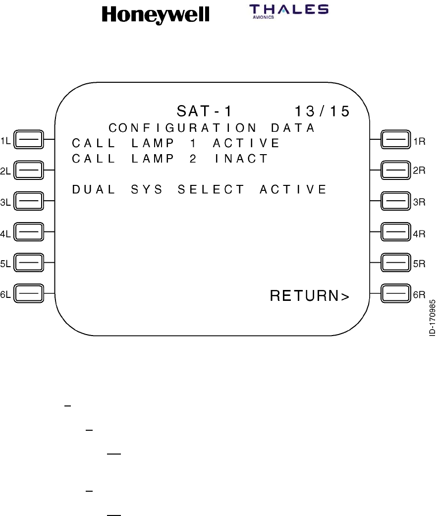
SYSTEM DESCRIPTION, INSTALLATION, AND MAINTENANCE MANUAL
MCS--4200/7200 Multi--Channel SATCOM System
23--20--35 15 Jul 2006
Honeywell International Inc. Do not copy without express permission of Honeywell.
Page 6--62
Figure 6-8 (Sheet 13). Configuration Data
(o) CONFIGURATION DATA Page 14 (Figure 6-8, sheet 14):
1Data Fields
aLine 3
(1) This line displays HPA CMND/STAT beginning in column 1, HGA
beginning in column 15, and LGA beginning in column 22.
bLine 4
(1) This line displays BACKOFF(DB) beginning in column 1. The HGA
HPA commanded backoff power level (in dB) is displayed (if
configured) right-justified in column 17 (as determined from the
HGA HPA command word Label 143). The LGA HPA commanded
backoff power level (in dB) is displayed (if configured) right-justified
in column 24 (as determined from the HGA HPA command word
Label 143. The ranged allowed for display of the backoff is 0 to 31
dB in increments of 1 dB.
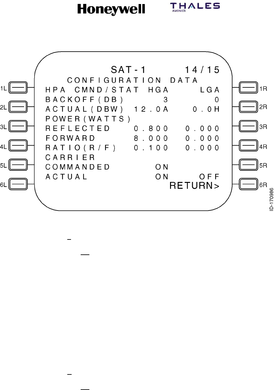
SYSTEM DESCRIPTION, INSTALLATION, AND MAINTENANCE MANUAL
MCS--4200/7200 Multi--Channel SATCOM System
23--20--35 15 Jul 2006
Honeywell International Inc. Do not copy without express permission of Honeywell.
Page 6--63
Figure 6-8 (Sheet 14). Configuration Data
cLine 5
(1) This line displays ACTUAL(DBW) beginning in column 1. The HGA
HPA reported power level (in dB Watts) is displayed (if configured)
right-justified in column 16 (as determined from the HGA HPA
status word Label 144). The state of the actual power out status
(APOS) bit is indicated as either A for actual or H for held and is
displayed in column 17. The LGA HPA commanded backoff power
level (in dB Watts) is displayed (if configured) right-justified in
column 23 (as determined from the LGA HPA status word Label
144). The state of the APOS status bit is displayed in column 24 as
previously stated. The allowable range for display of the actual
power is --11.5 to 19.0 dBW in increments of 0.5 dBW. If the actual
power value is outside the measurable range, dashes are displayed
for the actual power value. If valid data is not available for the HPA
status label, dashes are displayed to indicate the unknown data.
dLine 6
(1) This line displays POWER(WATTS) beginning in column 1.
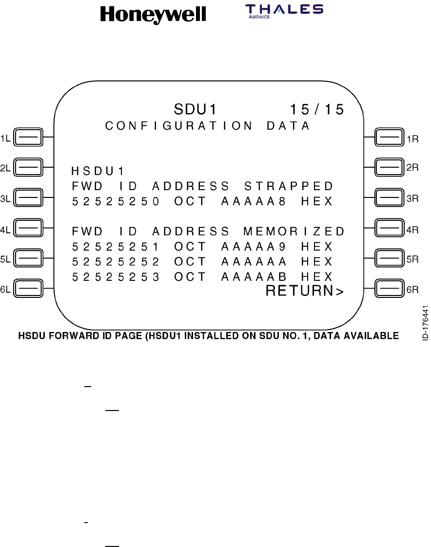
SYSTEM DESCRIPTION, INSTALLATION, AND MAINTENANCE MANUAL
MCS--4200/7200 Multi--Channel SATCOM System
23--20--35 15 Jul 2006
Honeywell International Inc. Do not copy without express permission of Honeywell.
Page 6--64
Figure 6-8 (Sheet 15). Configuration Data
eLine 7
(1) This line displays REFLECTED beginning in column 1. The HGA
HPA reflected power level (in Watts) is displayed (if configured)
right-justified in column 17 (as determined from the HGA HPA ). The
LGA HPA reflected power level (in Watts) is displayed (if configured)
right-justified in column 24 (as determined from the LGA HPA ). The
allowable range for the display of the reflected power value is 0.000
to 25.056 Watts. If the power level is unavailable, dashes are
displayed.
fLine 8
(1) This line displays FORWARD beginning in column 1. The HGA HPA
reflected power level (in Watts) is displayed (if configured)
right-justified in column 17 (as determined from the HGA HPA). The
LGA HPA reflected power level (in Watts) is displayed (if configured)
right-justified in column 24 (as determined from the LGA HPA). The
allowable range for the display of the reflected power value is 0.000
to 80.000 Watts. If the power level is unavailable, dashes are
displayed.

SYSTEM DESCRIPTION, INSTALLATION, AND MAINTENANCE MANUAL
MCS--4200/7200 Multi--Channel SATCOM System
23--20--35 15 Jul 2006
Honeywell International Inc. Do not copy without express permission of Honeywell.
Page 6--65
gLine 9
(1) This line displays RATIO(R/F) beginning in column 1. The HGA
HPA reflected power to forward power ratio is displayed (if
configured) right-justified in column 17 (as determined from the
HGA HPA). The LGA HPA reflected power to forward power ratio is
displayed (if configured) right-justified in column 24 (as determined
from the LGA HPA). The allowable range for the display of the
reflected power to forward power ratio is 0.000 to 1.000 Watts. If the
reported ratio is over-range, the text OVER is displayed. If the ratio
number is unavailable, dashes are displayed.
NOTE: The over-range condition occurs when the forward power
is more than 50 Watts while the reflected power is at the
maximum of 25.056 Watts. The HPA indicates the
over-range condition through the solo word ratio value of
FFH.
hLine 10
(1) This line displays CARRIER beginning in column 1.
iLine 11
(1) This line displays COMMANDED beginning in column 1. The HGA
HPA commanded carrier state is displayed (if configured)
right-justified in column 17 (as determined from the HGA HPA). The
LGA HPA commanded carrier state is displayed (if configured)
right-justified in column 24 (as determined from the LGA HPA). The
commanded carrier state is displayed as either ON or OFF.
jLine 12
(1) This line displays ACTUAL beginning in column 1. The HGA HPA
actual carrier state is displayed (if configured) right-justified in
column 17 (as determined from the HGA HPA). The LGA HPA
commanded carrier state is displayed (if configured) right-justified in
column 24 (as determined from the LGA HPA). The actual carrier
state is displayed as either ON or OFF.
kLine 13
(1) This line displays RETURN> right-justified. Pushing LS key 6L
causes the page display to revert to the SAT--N (SATCOM
MAINTENANCE) page.

SYSTEM DESCRIPTION, INSTALLATION, AND MAINTENANCE MANUAL
MCS--4200/7200 Multi--Channel SATCOM System
23--20--35 15 Jul 2006
Honeywell International Inc. Do not copy without express permission of Honeywell.
Page 6--66
(7) DATALOADERMENUPage
(a) General
1Access to this page is from SATCOM SUBMENU page (or the SATCOM
MAINTENANCE page). The access page depends on the configuration of
the aircraft as defined in Figure 6-2. The purpose of this page is to supply a
means of commanding data loader actions. See Figure 6-9 for example
pages.
(b) Data Fields
1Field 1L
aThis field displays DATA LOADER in the label line and the data loader
status in the data line. Possible status displays depend on the data
loader status as follows:
•NOT CONNECTED -- Displayed when the status of both data loader
is absent.
•CONNECTED -- Displayed when at least one data loader status is
CONNECTED, and the status of neither data loaders is READY,
BUSY, or ERROR.
•READY -- Displayed when a data loader status is READY.
•BUSY -- Displayed when a data loader status is BUSY.
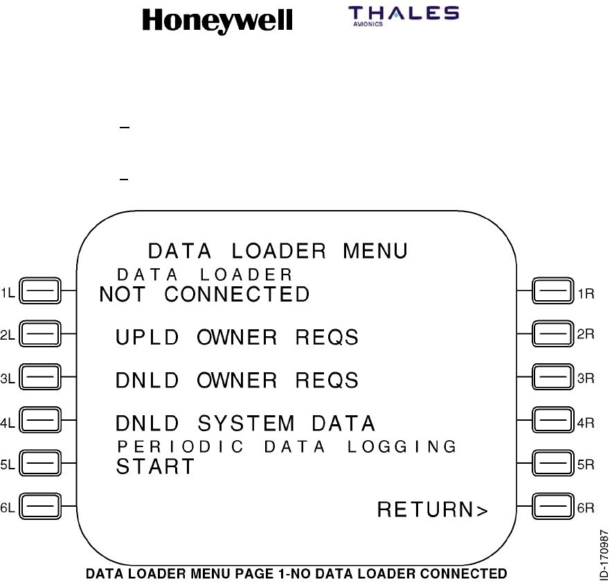
SYSTEM DESCRIPTION, INSTALLATION, AND MAINTENANCE MANUAL
MCS--4200/7200 Multi--Channel SATCOM System
23--20--35 15 Jul 2006
Honeywell International Inc. Do not copy without express permission of Honeywell.
Page 6--67
bREADY must be displayed before data uploading or downloading can
be performed.
cAsterisks are only displayed adjacent to the left LS keys when the data
loader status is READY.
Figure 6-9 (Sheet 1). DATA LOADER MENU
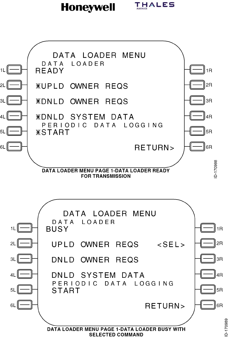
SYSTEM DESCRIPTION, INSTALLATION, AND MAINTENANCE MANUAL
MCS--4200/7200 Multi--Channel SATCOM System
23--20--35 15 Jul 2006
Honeywell International Inc. Do not copy without express permission of Honeywell.
Page 6--68
Figure 6-9 (Sheet 2). DATA LOADER MENU
Figure 6-9 (Sheet 3). DATA LOADER MENU
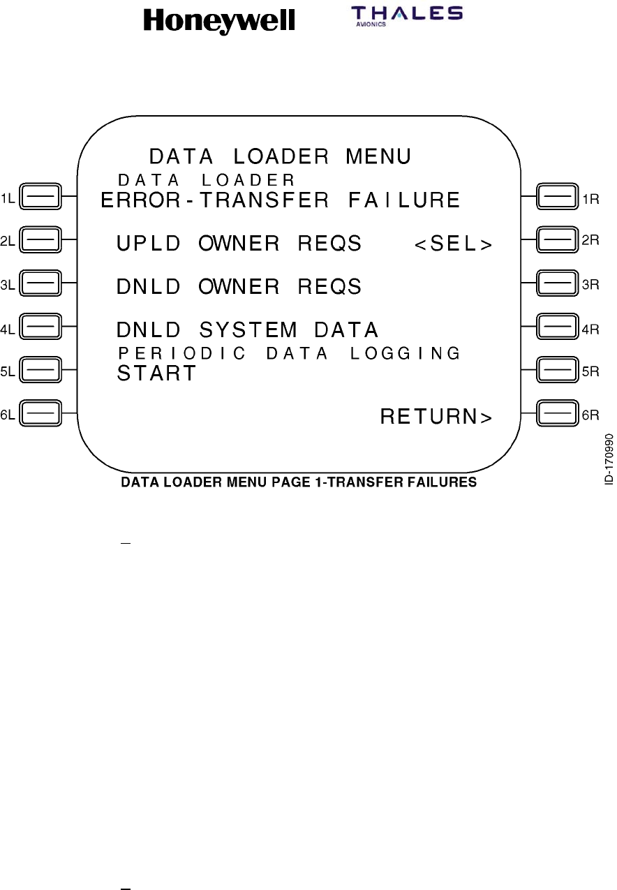
SYSTEM DESCRIPTION, INSTALLATION, AND MAINTENANCE MANUAL
MCS--4200/7200 Multi--Channel SATCOM System
23--20--35 15 Jul 2006
Honeywell International Inc. Do not copy without express permission of Honeywell.
Page 6--69
Figure 6-9 (Sheet 4). DATA LOADER MENU
dSeveral messages are displayed when the status of a data loader is
ERROR . If the status becomes ERROR, an appropriate error message
is appended to ERROR, separated by a dash. Possible error messages
are displayed as follows:
•DISK FULL
•TRANSFER FAILURE
•FILE NOT FOUND
•CRC FAILURE
•BAD FILE HEADER
•BAD OWNER REQS VER
•OPEN DISK
•CLOSE DISK
•WRITE PROTECT
•COMP ORT NOT ALLOW.
eThe TRANSFER FAILURE error message indicates an ARINC 615
protocol transfer failure (e.g., loss of communications). The OPEN DISK
and CLOSE DISK error messages are displayed when an undefined
disk command completion code is received. COMP ORT NOT ALLOW
is indicated when a composite ORT version upload is attempted and the
setting for ORT item liv does not allow it.
SYSTEM DESCRIPTION, INSTALLATION, AND MAINTENANCE MANUAL
MCS--4200/7200 Multi--Channel SATCOM System
23--20--35 15 Jul 2006
Honeywell International Inc. Do not copy without express permission of Honeywell.
Page 6--70
2Fields 2L thru 5L
aThese fields display prompts in the data line for commanding data
loader actions. The prompts that can be displayed for the indicated
DATA LOADER MENU page (1 or 2) are as given in Table 6-16.
Table 6-16. DATA LOADER MENU Page Prompts
LS Key Display Prompt
2L UPLD OWNER REQS
3L DNLD OWNER REQS
4L DNLD SYSTEM DATA
5L START
bThe display prompts given in Table 6-16 command the following actions:
•UPLD OWNER REQS -- upload owner requirements table
•DNLD OWNER REQS -- download owner requirements table
•DNLD SYSTEM DATA -- download all event/fail/config/ORT logs
cAsterisks are only displayed beside the adjacent left LS key when the
data loader status is READY (except as stated below). When asterisks
are displayed, pushing the left LS key adjacent to the desired action
commands the data loader to initiate that action.
dUploads are allowed regardless of the log-on state (composite uploads
are inhibited only by ORT item liv and not the log-on state).
eOnce a left LS key is pushed, the <SEL> message is displayed to the
right of the selected data loader action, right-justified. The data loader
status changes to BUSY and data transfers occur. There is only one
data loader command selected at a time. The <SEL> message remains
displayed until the 6L key is pushed if the data loader status becomes
ERROR after a left LS key is pushed. When the data transfer is
completed, or after an error has been acknowledged, the <SEL>
message is removed and the data loader status changes appropriately.
3Fields 5L and 5R
aPERIODIC DATA LOGGING is displayed in the label line beginning in
column 2. In the data line, START is displayed adjacent to the 5L key.
No asterisk is displayed beside the 5L key when the data loader status
is either NOT CONNECTED, CONNECTED, BUSY, or ERROR.

SYSTEM DESCRIPTION, INSTALLATION, AND MAINTENANCE MANUAL
MCS--4200/7200 Multi--Channel SATCOM System
23--20--35 15 Jul 2006
Honeywell International Inc. Do not copy without express permission of Honeywell.
Page 6--71
bWhen the START prompt is selected by pushing the 5L key when the
data loader status is READY:
•Periodic data logging starts
•The asterisk next to START is removed
•The <SEL> message is displayed beginning in column 8
•STOP is displayed adjacent to the 5R key.
cPeriodic data logging continues until the 5R key is pushed, at that time
the data line display reverts to its original state (i.e., only the START
prompt with or without an asterisk as appropriate).
dThe <SEL> message remains displayed and the STOP prompt is
blanked if the data loader status changes to ERROR after periodic data
logging has started. This condition remains until the error is
acknowledged by pushing the 6L key and/or the data loader status
changes, at that time the data line display changes as appropriate.
4Field 6L
a6L -- This data line displays the *ACK ERROR prompt. This prompt is
displayed when the data loader status is ERROR. Pushing the 6L key
causes the SDU to remove the ERROR status and display the current
data loader status (i.e., NOT CONNECTED or CONNECTED) in the 1L
data line.
bThe SDU completes the upload/download data transfer by commanding
the data loader transfer complete function. The data loader responds
with a TRANSFER COMPLETE indication and enters a no loop. To
return the data loader to the READY state, the user must cause the
data loader to read the configuration file on the diskette (i.e., cycle data
loader power or remove/insert the diskette).
5Field 6R
a6R -- This data line displays the RETURN> prompt. Pushing the 6R key
causes the display to revert to the SATCOM SUBMENU page (or
SATCOM MAINTENANCE page) as appropriate.
(8) LAST LEG REPORT Page
(a) Access to this page is from the SAT--N (i.e., SATCOM MAINTENANCE) page.
The purpose of this page is to display Class 1 and 2, Level 1 diagnosed, failures
reported during the last leg. See Figure 6-10 for example pages.

SYSTEM DESCRIPTION, INSTALLATION, AND MAINTENANCE MANUAL
MCS--4200/7200 Multi--Channel SATCOM System
23--20--35 15 Jul 2006
Honeywell International Inc. Do not copy without express permission of Honeywell.
Page 6--72
(b) The Last Leg Report lists two failures per page if a failure is present during the
last leg. These two sets of lines display Class 1 and 2, Level 1 diagnosed, last
leg failures. Failures are displayed in chronological order (i.e., the most recent
detected failure last) with no more than two failures displayed per page. The
number of LAST LEG REPORT pages depends on the number of failures to
report (up to a maximum of 99 pages). When there is an odd number of failures
to report, the odd failure is displayed on a page of its own in lines 5, 6, and 7,
and lines 9, 10, and 11 are blank. If there are no failures to report, lines 6, 7, 9,
10, and 11 are blank. Line 5 displays NO FAULT DETECTED beginning in
column 4 if there are no failures to report.
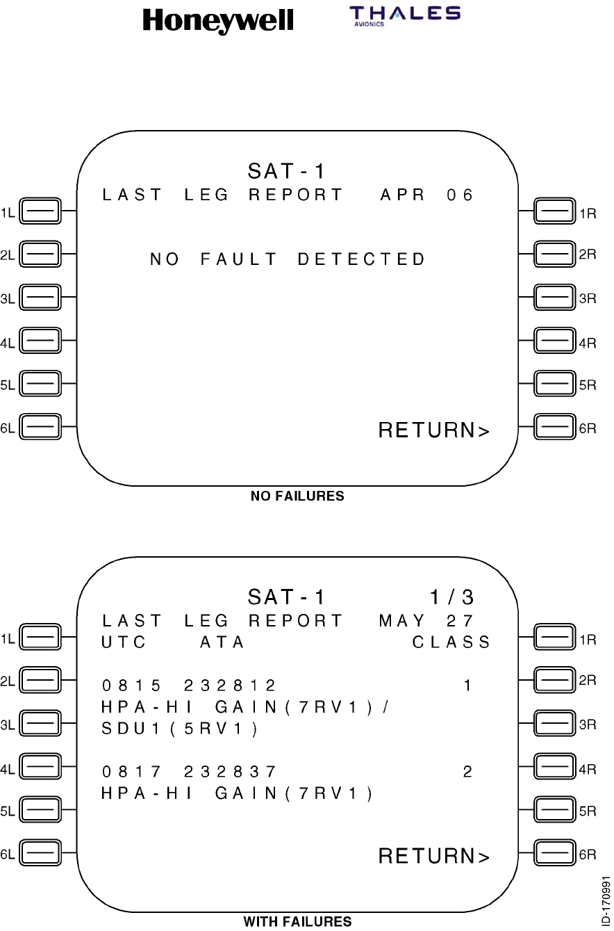
SYSTEM DESCRIPTION, INSTALLATION, AND MAINTENANCE MANUAL
MCS--4200/7200 Multi--Channel SATCOM System
23--20--35 15 Jul 2006
Honeywell International Inc. Do not copy without express permission of Honeywell.
Page 6--73
Figure 6-10. LAST LEG REPORT Page

SYSTEM DESCRIPTION, INSTALLATION, AND MAINTENANCE MANUAL
MCS--4200/7200 Multi--Channel SATCOM System
23--20--35 15 Jul 2006
Honeywell International Inc. Do not copy without express permission of Honeywell.
Page 6--74
(c) Line 5 and, if applicable, line 9 display the universal time coordinated (UTC)
beginning in column 1, and ATA beginning in column 6, and the class number in
column 23.
(d) The UTC is displayed as hhmm, where hh represents the UTC hours from 00 to
23, and mm represents the UTC minutes from 00 to 59. The UTC is the time of
the failure reporting as stored in the SDU system failure memory log. Dashes are
displayed if no valid UTC data is available.
(e) The ATA number is displayed as aaaaaa, where aaaaaa represents the ATA
reference number of the reported failure as specified in paragraph 3.E. for each
type of CFDS. For CFDS type none, no ATA number is displayed.
(f) The class number is displayed as c, where c represents the class (1 or 2) of the
failure.
(9) PREVIOUS LEGS REPORT Page
(a) Access to this page is from the SAT--N (i.e., SATCOM MAINTENANCE) page.
The purpose of this page is to display Class 1 and 2, Level 1 diagnosed, failures
reported during previous legs. See Figure 6-11 for example pages.
(b) The Previous Leg Report lists two failures per page if a failure was present
during the previous leg. These two sets of lines display Class 1 and 2, Level 1
diagnosed, last leg failures. Failures within each flight leg are displayed in
chronological order (i.e., the most recent detected failure last) with no more than
two failures displayed per page. However, the flight leg display is in reverse
chronological order (i.e., flights go back in time while failures for each individual
flight go forward in time).
(c) The number of PREVIOUS LEGS REPORT pages depends on the number of
failures to report (up to a maximum of 99 pages). If there are no failures to
report, lines 6, 7, 9, 10, and 11 are blank. Line 5 displays NO FAULT DETECTED
beginning in column 4 if there are no failures to report.
(d) Failures from different flight legs with the same aircraft identification are mixed on
the same page. When the last leg falls in lines 5, 6, and 7, failures from the
previous flight leg are displayed on the same page in lines 9, 10, and 11.
(e) When the given flight leg has a different aircraft identification recorded than the
flight leg before it, the failure display begins in lines 5, 6, and 7 on the next page
of the multiple page sequence. When there are no failures to report for a given
flight leg, nothing is reported for that flight leg (i.e., the flight leg is skipped).
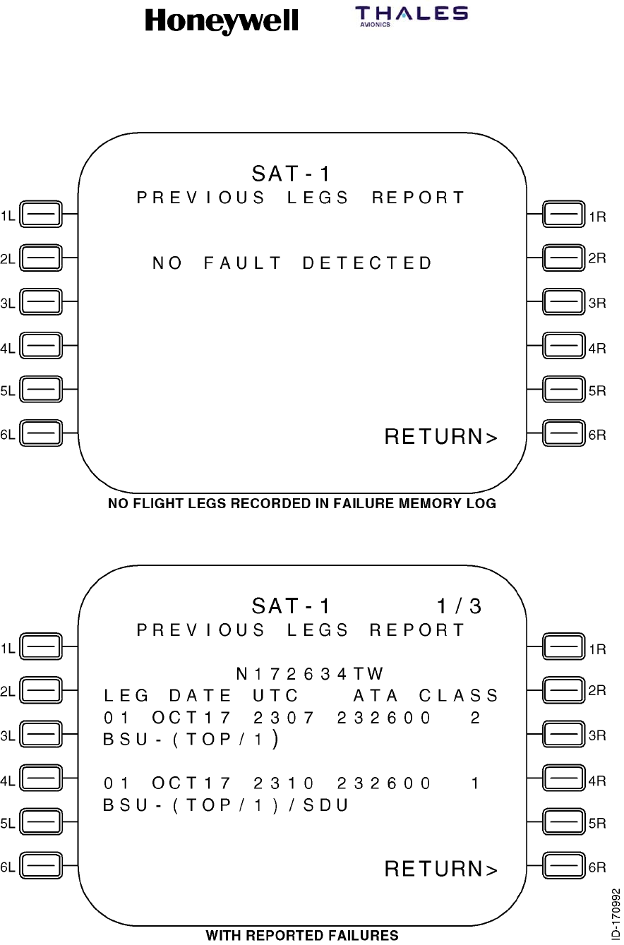
SYSTEM DESCRIPTION, INSTALLATION, AND MAINTENANCE MANUAL
MCS--4200/7200 Multi--Channel SATCOM System
23--20--35 15 Jul 2006
Honeywell International Inc. Do not copy without express permission of Honeywell.
Page 6--75
Figure 6-11 (Sheet 1). PREVIOUS LEG REPORT Page
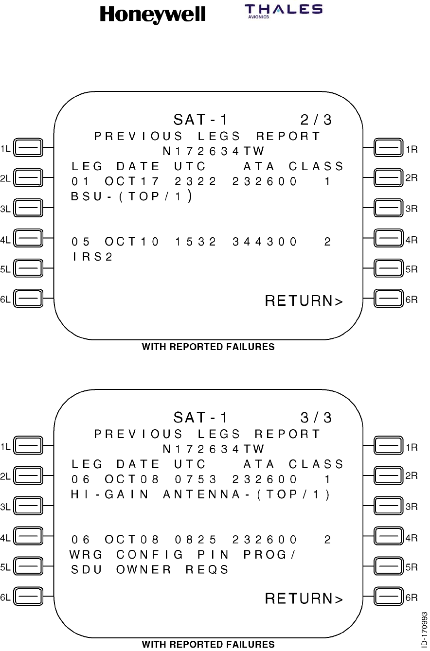
SYSTEM DESCRIPTION, INSTALLATION, AND MAINTENANCE MANUAL
MCS--4200/7200 Multi--Channel SATCOM System
23--20--35 15 Jul 2006
Honeywell International Inc. Do not copy without express permission of Honeywell.
Page 6--76
Figure 6-11 (Sheet 2). PREVIOUS LEG REPORT Page

SYSTEM DESCRIPTION, INSTALLATION, AND MAINTENANCE MANUAL
MCS--4200/7200 Multi--Channel SATCOM System
23--20--35 15 Jul 2006
Honeywell International Inc. Do not copy without express permission of Honeywell.
Page 6--77
(f) Line 5 and line 9 (if applicable) display the flight leg number beginning in column
1, the UTC beginning in column 10, and the ATA number beginning in column
15.
(g) The flight leg is displayed as fl, where fl represents the flight leg number from 01
to either:
•The number of flight legs recorded in the SDU system failure memory log
•63 flight legs
•From 01 to the maximum number of flight legs that can be displayed given the
PREVIOUS LEGS REPORT page limit of 99.
(h) The date is displayed as mmmdd, where mmm represents the month of the year
as JAN, FEB, MAR, APR, MAY, JUN, JUL, AUG, SEP, OCT, NOV, or DEC, and
dd represents the day of the month from 01 to 31. The date is the date of the
flight leg number as stored in the SDU system failure memory log. Dashes are
displayed if no valid UTC data is available.
(i) The UTC time is displayed as hhmm, where hh represents the UTC hours from
00 to 23, and mm represents the UTC minutes from 00 to 59. The UTC is the
time of the failure reporting as stored in the SDU system failure memory log.
Dashes are displayed if no valid UTC data is available.
(j) The ATA number is displayed as aaaaaa, where aaaaaa represents the ATA
reference number of the reported failure as specified in paragraph 3.E. for each
type of CFDS. For CFDS type none, no ATA number is displayed.
(k) The class number is displayed as c, where c represents the class (1 or 2) of the
failure.
(10) LRU IDENTIFICATION Page
(a) Access to this page is from the SAT--N (i.e., SATCOM MAINTENANCE) page.
The purpose of this page is to display a list of all installed LRUs with their
associated part numbers, modification levels, and serial numbers, and to display
ORT identification data. See Figure 6-12 for example pages.
(b) If a Honeywell/Thales HPA is installed, the associated part/serial number is
displayed; otherwise the HPA display entry is removed. The number of LRU
IDENTIFICATION pages depends on the number of LRUs to list.
(c) For the LRUs, line 4 and, if applicable, line 9 display a three letter acronym
representing the installed LRU. The possible LRU acronyms are given in
Table 6-17.
SYSTEM DESCRIPTION, INSTALLATION, AND MAINTENANCE MANUAL
MCS--4200/7200 Multi--Channel SATCOM System
23--20--35 15 Jul 2006
Honeywell International Inc. Do not copy without express permission of Honeywell.
Page 6--78
Table 6-17. LRU Acronyms
LRU Acronym LRU Name
SDU Satellite Data Unit
HPH High Power Amplifier -- High Gain Antenna
HPL High Power Amplifier -- Low Gain Antenna
HSU High--Speed Data Unit
(d) For the LRUs, line 5 and, if applicable, line 10 display P/N beginning in column 1,
the LRU end-item part number beginning in column 6, and the software
modification level in columns 23 and 24.
(e) The P/N is displayed as bbbbbbb--hhsss, where bbbbbbb--hhsss represents the
LRU end-item part number consisting of a seven-digit LRU base part number
(i.e., bbbbbbb), a two-digit hardware configuration number (i.e., hh), and a
three-digit software configuration number (i.e., sss). Dashes are displayed if no
valid data is available.
(f) The software modification level is displayed as nn, where nn represents up to a
two-character LRU software modification level.
(g) Line 6 and, if applicable, line 11 display S/N beginning in column 1 and the LRU
serial number beginning in column 5. The S/N is diplayed as ssssssss, where
ssssssss represents the LRU serial number. Dashes are displayed if no valid
data is available.
(h) For the Honeywell/Thales MCS system, the two-digit LRU hardware and LRU
serial number must be manually entered through the CMT interface for valid data
to be available for display. This data is stored during an LRU end-item test. All
other numbers reside within the LRU software. For non-Honeywell/Thales
interfacing HPAs, no such data is available to the SDU, therefore, dashes are
displayed for the HPA part/serial numbers.
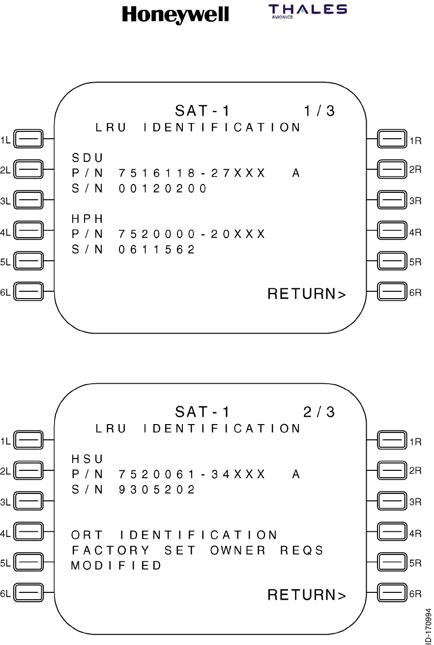
SYSTEM DESCRIPTION, INSTALLATION, AND MAINTENANCE MANUAL
MCS--4200/7200 Multi--Channel SATCOM System
23--20--35 15 Jul 2006
Honeywell International Inc. Do not copy without express permission of Honeywell.
Page 6--79
Figure 6-12 (Sheet 1). LRU IDENTIFICATION Page
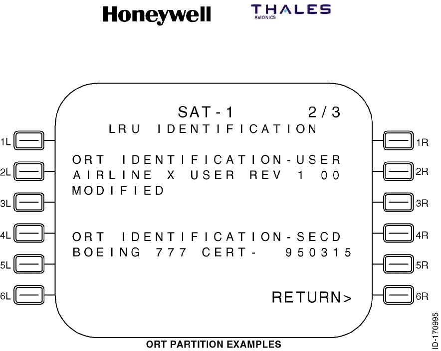
SYSTEM DESCRIPTION, INSTALLATION, AND MAINTENANCE MANUAL
MCS--4200/7200 Multi--Channel SATCOM System
23--20--35 15 Jul 2006
Honeywell International Inc. Do not copy without express permission of Honeywell.
Page 6--80
Figure 6-12 (Sheet 2). LRI IDENTIFICATION Page
(i) The ORT identification is displayed in either lines 4, 5, and 6, or in lines 9, 10,
and 11 depending on where the LRU list falls. Line 4 or line 9, as appropriate,
displays the header ORT IDENTIFICATION left-justified. If the ORT is a
partitioned version, the text, --USER, is added to the end of the header text. Line
5 or line 10, as appropriate, displays the ORT 24-character description as
contained in ORT item xxxiii (refer to Appendix B). Line 6 or line 11, as
appropriate, displays MODIFIED left-justified, if the state of ORT item xxxvii (refer
to Appendix C) is modified. If the state of ORT item xxxvii is unmodified, the
MODIFIED flag is not displayed.
(j) If the ORT is loaded as separate partitions, the secured ORT identification is
displayed in either lines 4, 5, and 6, or in lines 9, 10, and 11 depending on where
the first ORT ident falls. Line 4 or line 9, as appropriate, displays the header ORT
IDENTIFICATION--SECD left-justified. Line 5 or line 10, as appropriate, displays
the ORT 24-character description as contained in ORT item liii (refer to Appendix
C) for the secured partition. Line 6 or line 11, as appropriate, displays MODIFIED
left-justified, if the state of the ORT secured partition modified flag (refer to
Appendix C) is modified. If the state of the ORT secured partition modified flag is
unmodified, the MODIFIED flag is not displayed.

SYSTEM DESCRIPTION, INSTALLATION, AND MAINTENANCE MANUAL
MCS--4200/7200 Multi--Channel SATCOM System
23--20--35 15 Jul 2006
Honeywell International Inc. Do not copy without express permission of Honeywell.
Page 6--81
(11) TROUBLE SHOOTING DATA Page
(a) General
1Access to this page is from the SAT--N (i.e., SATCOM MAINTENANCE)
page. The purpose of this page is to display Class 1 and 2, Level 1,
diagnosed failures reported during the last leg and previous legs. See
Figure 6-13 for example pages.
2The Trouble Shooting Data pages display the class 1 and 2 last leg and
previous legs failure details. Failures are displayed in chronological order
(i.e., the most recent detected failure last) with one failure displayed per
page. Flight leg display order is reverse chronological (i.e., flights go back in
time while failures for each individual flight go forward in time). The number
of pages depends on the number of failures to report (up to 64 flight legs or
99 pages).
(b) Data Fields
1Line 4
aLine 4 displays the date beginning in column 2 and the UTC beginning
in column 8. The date and time are displayed as follows.
bThe month is displayed as mmm, where mmm represents the month of
the year as JAN, FEB, MAR, APR, MAY JUN, JUL, AUG, SEP, OCT,
NOV, or DEC.
cThe day is displayed as dd, where dd represents the day of the month
from 01 to 31.
dThe UTC is displayed as hh:mm, where hh represents the UTC hours
from 00 to 23 and mmm represents the UTC minutes from 00 to 59. The
UTC is the time the failure was stored in the failure memory log on this
flight leg. Dashes are displayed if no valid UTC data is available.
eLine 4 displays the header, LEG, beginning in column 15 and the flight
leg count right-justified from column 23.
2Line 5
aLine 5 displays beginning in column 2 the LRU abbreviated name of up
to five characters that corresponds to the level 1 failure code. The SRU
abbreviated name of up to five characters is displayed beginning in
column 8. If the SRU designation in the failure code is 0, no SRU
abbreviation is displayed. The LRU failure code is displayed as two
hexadecimal digits beginning in column 17. The SRU failure code is
displayed as one hexadecimal digit beginning in column 20. The failure
code is displayed as two hexadecimal digits beginning in column 22.
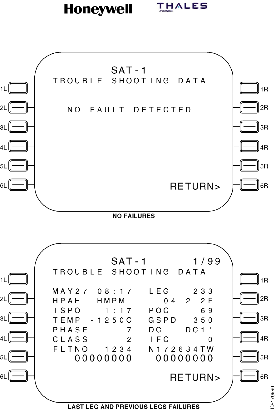
SYSTEM DESCRIPTION, INSTALLATION, AND MAINTENANCE MANUAL
MCS--4200/7200 Multi--Channel SATCOM System
23--20--35 15 Jul 2006
Honeywell International Inc. Do not copy without express permission of Honeywell.
Page 6--82
Figure 6-13. TROUBLESHOOTING DATA Page

SYSTEM DESCRIPTION, INSTALLATION, AND MAINTENANCE MANUAL
MCS--4200/7200 Multi--Channel SATCOM System
23--20--35 15 Jul 2006
Honeywell International Inc. Do not copy without express permission of Honeywell.
Page 6--83
3Line 6
aLine 6 displays the time since power--on (TSPO) header beginning in
column 2, and the LRU power--on counter (POC) header beginning in
column 15. The LRU time since power-on is displayed right-justified
from column 12.
bThe TSPO is displayed as hhh:mm, where hhh represents the hours of
the elapsed time since the unit powered up from 0 to 999, and mm
represents the minutes portion of the elapsed time from 0 to 59.
cLine 6 displays the power-on count value from 0 to 65535 right-justified
from column 23.
4Line 7
aLine 7 displays the headers, TEMP, beginning in column 2, and
groundspeed (GSPD), beginning in column 15. The LRU-failed SRU (or
PSU) temperature is displayed right-justified from column 12. Dashes
are displayed if no valid temperature data is available. The GSPD is
displayed right-justified from column 23.
5Line 8
aLine 8 displays the headers, PHASE, beginning in column 2, and DC,
beginning in column 15. The flight phase is displayed right-justified from
column 12. If a numbered flight phase is not available, then an aor gis
shown in column 12, as appropriate. The DC state is displayed as DC0,
DC0’, DC1, DC1’, or DC2 right-justified from column 23.
6Line 9
aLine 9 displays the headers, CLASS, beginning in column 2, and IFC,
beginning in column 15. The failure class is displayed in column 12. The
intermittent failure count is displayed in column 23.
7Line 10
aLine 10 displays the header FLTNO beginning in column 2. The flight
number is displayed right-justified from column 12. The aircraft tail
number is displayed right-justified from column 23. Dashes are
displayed if no valid flight number or tail number data is available.
8Line 11
aLine 11 displays the failure parameter as eight hexadecimal digits
beginning in column 5. The associated parameter is displayed as eight
hexadecimal digits beginning in column 16.
(12) LAST LEG CLASS 3 FAULTS Page
(a) Access to this page is from the SAT--N (CFDS SATCOM Maintenance Menu)
page. The purpose of this page is to display Class 3, Level 1 diagnosed, failures
reported during the last leg. See Figure 6-14 for example pages.
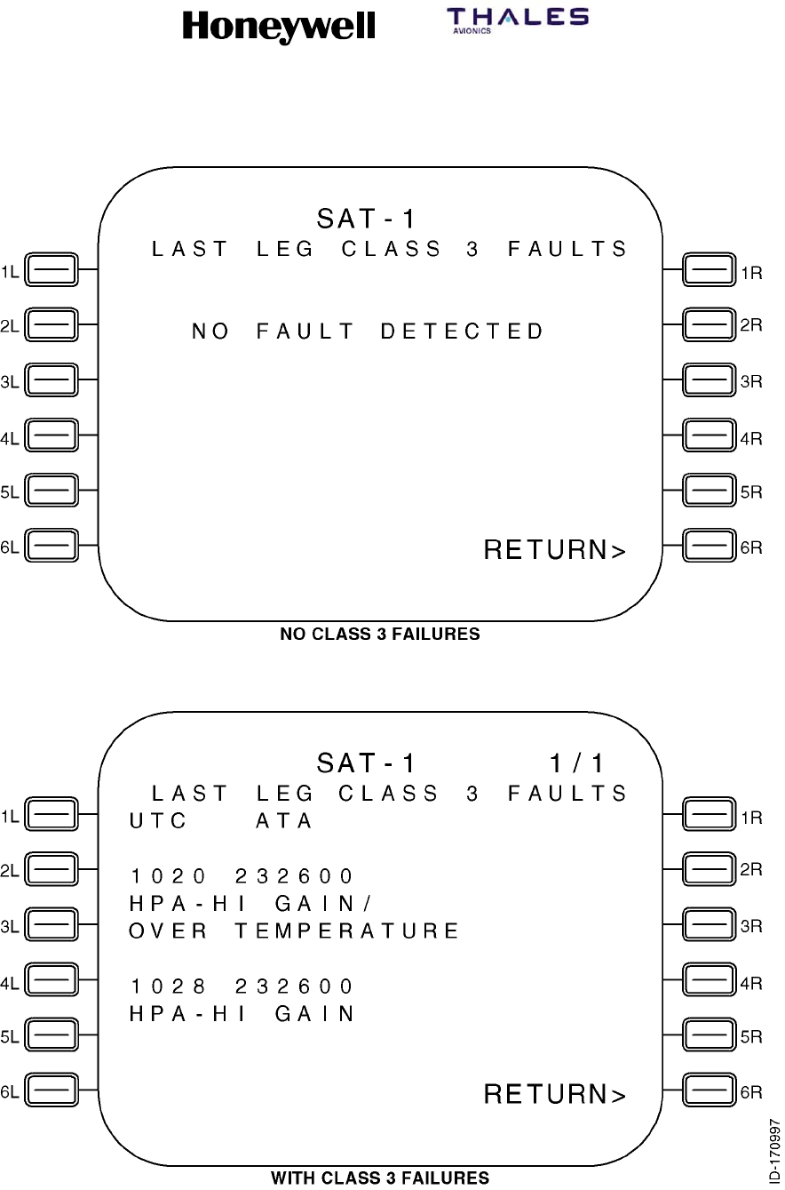
SYSTEM DESCRIPTION, INSTALLATION, AND MAINTENANCE MANUAL
MCS--4200/7200 Multi--Channel SATCOM System
23--20--35 15 Jul 2006
Honeywell International Inc. Do not copy without express permission of Honeywell.
Page 6--84
Figure 6-14. LAST LEG CLASS 3 FAULTS Page

SYSTEM DESCRIPTION, INSTALLATION, AND MAINTENANCE MANUAL
MCS--4200/7200 Multi--Channel SATCOM System
23--20--35 15 Jul 2006
Honeywell International Inc. Do not copy without express permission of Honeywell.
Page 6--85
(b) The Last Leg Class 3 Faults lists two Class 3 faults per page if Class 3 faults are
present during the last leg. These two sets of lines display Class 3, Level 1
diagnosed, last leg failures. Failures are displayed in chronological order (i.e.,
the most recent detected failure last) with no more than two failures displayed
per page.
(c) The number of LAST LEG CLASS 3 FAULTS pages depends on the number of
failures to report (up to a maximum of 99 pages). When there is an odd number
of failures to report, the odd failure is displayed on a separate page in lines 5, 6,
and 7, and lines 9, 10, and 11 are blank. If there are no failures to report, lines 6,
7, 9, 10, and 11 are blank. Line 5 displays NO FAULT DETECTED beginning in
column 4 if there are no failures to report.
(d) Line 5 and, if applicable, line 9 display the UTC beginning in column 1 and the
ATA number beginning in column 6.
(e) The UTC number is displayed as hh:mm, where hh represents the UTC hours
from 00 to 23, and mm represents the UTC minutes from 00 to 59. The UTC is
the time of the failure reporting as stored in the SDU system failure memory log.
Dashes are displayed if no valid UTC data is available.
(f) The ATA number is displayed as aaaaaa, where aaaaaa represents the ATA
reference number of the reported failure as specified in paragraph 3.E. for each
type of CFDS. For CFDS type none, no ATA number is displayed.
(13) GROUND REPORT Page
(a) Access to this page is from the SAT--N (i.e., SATCOM MAINTENANCE) page.
The purpose of this page is to display Class 1, 2, or 3, Level 1 diagnosed ground
failures that occurred during the last leg. See Figure 6-15 for example pages.
(b) The Ground Report lists two failures per page if failures are detected during the
last leg. These two sets of lines display Class 1, 2, and 3, Level 1 diagnosed,
last leg failures. Failures are displayed in chronological order (i.e., the most
recent detected failure last) with no more than two failures displayed per page.
(c) The number of GROUND REPORT pages depends on the number of failures to
report (up to 99 pages). When there is an odd number of failures to report, the
odd failure is displayed on a separate page in lines 5, 6, and 7, and lines 9, 10,
and 11 are blank. If there are no failures to report, lines 6, 7, 9, 10, and 11 are
blank. Line 5 displays NO FAULT DETECTED beginning in column 4 if there are
no failures to report.
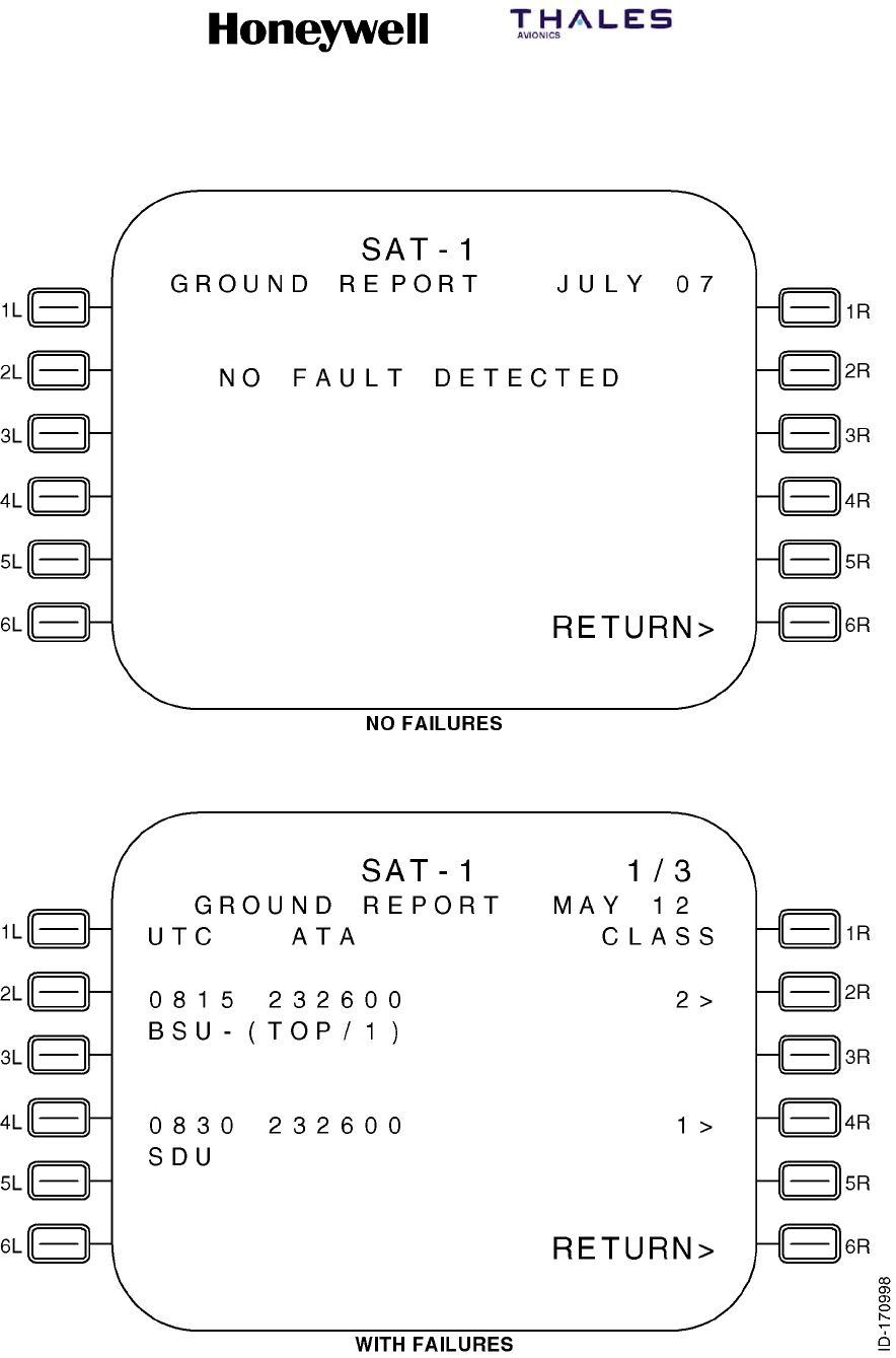
SYSTEM DESCRIPTION, INSTALLATION, AND MAINTENANCE MANUAL
MCS--4200/7200 Multi--Channel SATCOM System
23--20--35 15 Jul 2006
Honeywell International Inc. Do not copy without express permission of Honeywell.
Page 6--86
Figure 6-15. GROUND REPORT Page

SYSTEM DESCRIPTION, INSTALLATION, AND MAINTENANCE MANUAL
MCS--4200/7200 Multi--Channel SATCOM System
23--20--35 15 Jul 2006
Honeywell International Inc. Do not copy without express permission of Honeywell.
Page 6--87
(14) GROUND REPORT (TROUBLE SHOOTING DATA) Page
(a) General
1Access to this page is from the GROUND REPORT page. The purpose of
this page is to display Class 1, 2, or 3, Level 1 diagnosed ground failures
that occurred during the last leg ground report. See Figure 6-16 for example
pages.
2One failure is listed per page if a failure is present. These lines display Class
1, 2, and 3, Level 1 diagnosed, last leg ground report failure details
corresponding to the Level 1 failures from which the troubleshooting data
was initiated. Failures are displayed in chronological order (i.e., the most
recent detected failure last) with one failure displayed per page.
(b) Line 4
1Line 4 displays the date beginning in column 2 and the UTC beginning in
column 8. The date and time are displayed as follows.
2The month is displayed as mmm, where mmm represents the month of the
year as JAN, FEB, MAR, APR, MAY, JUN, JUL, AUG, SEP, OCT, NOV, or
DEC.
3The day is displayed as dd, where dd represents the day of the month from
01 to 31.
4The UTC is displayed as hh:mm, where hh represents the UTC hours from
00 to 23 and mm represents the UTC minutes from 00 to 59. The UTC is the
time the failure was stored in the failure memory log on this flight leg.
Dashes are displayed if no valid UTC data is available.
(c) Line 5
1Line 5 displays the LRU abbreviated name of up to five characters that
corresponds to the Level 1 failure code. The SRU abbreviated name of up to
five characters is displayed beginning in column 8. If the SRU designation in
the failure code is 0, no SRU abbreviation is displayed. The LRU failure
code is displayed as two hexadecimal digits beginning in column 17. The
SRU failure code is displayed as one hexadecimal digit beginning in column
20. The failure code is displayed as two hexadecimal digits beginning in
column 22.
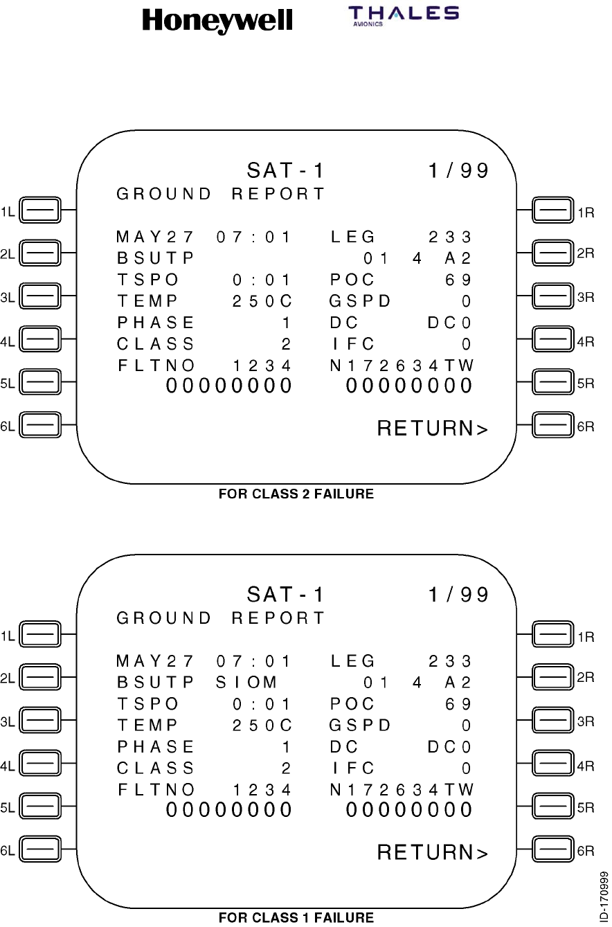
SYSTEM DESCRIPTION, INSTALLATION, AND MAINTENANCE MANUAL
MCS--4200/7200 Multi--Channel SATCOM System
23--20--35 15 Jul 2006
Honeywell International Inc. Do not copy without express permission of Honeywell.
Page 6--88
Figure 6-16. GROUND REPORT TROUBLE SHOOTING DATA Page

SYSTEM DESCRIPTION, INSTALLATION, AND MAINTENANCE MANUAL
MCS--4200/7200 Multi--Channel SATCOM System
23--20--35 15 Jul 2006
Honeywell International Inc. Do not copy without express permission of Honeywell.
Page 6--89
(d) Line 6
1Line 6 displays the headers, TSPO, beginning in column 2 and, POC,
beginning in column 15. The LRU time since power-on is displayed
right-justified from column 12.
2The UTC is displayed as hh:mm, where hh represents the UTC hours from
00 to 23 and mm represents the UTC minutes from 00 to 59. The UTC is the
time the failure was stored in the failure memory log on this flight leg.
Dashes are displayed if no valid UTC data is available.
3Line 6 displays the power-on count value from 0 to 65535 right-justified from
column 23.
(e) Line 7
1Line 7 displays the headers, TEMP, beginning in column 2, and GSPD,
beginning in column 15. The LRU-failed SRU (or PSU) temperature is
displayed right-justified from column 12. Dashes are displayed if no valid
temperature data is available. The groundspeed is displayed right-justified
from column 23.
(f) Line 8
1Line 8 displays the headers, PHASE, beginning in column 2, and DC,
beginning in column 15. The flight phase is displayed right-justified from
column 12. If a numbered flight phase is not available, then an aor gis
shown in column 12, as appropriate. The DC state is displayed as DC0,
DC0’, DC1, DC1’, or DC2 right-justified from column 23.

SYSTEM DESCRIPTION, INSTALLATION, AND MAINTENANCE MANUAL
MCS--4200/7200 Multi--Channel SATCOM System
23--20--35 15 Jul 2006
Honeywell International Inc. Do not copy without express permission of Honeywell.
Page 6--90
3. Maintenance Computer Interface
A. General
(1) The SDU is designed to interface with the Boeing 747--400 Central Maintenance
Computer (CMC) or the Boeing 777 On--board Maintenance System (OMS), the
Airbus Central Fault Display System (CFDS), and the McDonnell Douglas CFDS in
accordance with guidelines outlined in Boeing documents D220U050 (747--400 CMC
-- release date 3 June 1991) and D243W201--1 (777 OMS -- release date 30 October
1992) and Airbus document ABD0048 issue C, all of which supersede ARINC 604 for
their respective applications.
(2) The Boeing maintenance computers (i.e., 747--400 CMC and 777 OMS) are virtually
indistinguishable to the SDU. The operations to support these two systems are very
similar and, therefore, are presented together. The operations to support the Airbus
and McDonnell Douglas maintenance computers are very similar and, therefore, are
presented together. The SDU determines the aircraft type on which the SDU is
installed, and then supports only the functionality required by that particular system.
B. Boeing 747--400 CMC/777 OMS
(1) General
(a) The CMC and SDU communicate with each other through an ARINC 429 data
bus using ARINC 429 words.
(b) When the SDU receives the standard ground test command containing its
equipment ID and source destination identifier (SDI), the SDU responds by
setting the command word (ARINC label 350) acknowledge bit to ACK for four
seconds. The SDU initiates a system-wide functional test. As soon as possible
during the execution of the functional test, the SDU sets the SSM for ARINC
label 350 to functional test.
(2) CMC to SDU Communication -- Automatic Fault Reporting
(a) The CMC and SDU communicate with each other through an ARINC 429 data
bus using ARINC 429 words.
(b) When the SDU receives the standard ground test command containing its
equipment ID and source destination identifier (SDI), the SDU responds by
setting the command word (ARINC label 350) acknowledge bit to ACK for 4
seconds. The SDU then initiates a system-wide functional test. As soon as
possible during the execution of the functional test, the SDU sets the SSM for
ARINC label 350 to functional test.
(c) At the conclusion of the functional test, the SDU builds the fault summary words
using ARINC labels 350 thru 354 by mapping currently active failures to the
appropriate bits in the words. Once the words are built they are latched for 30
seconds, then the SDU returns to automatic fault reporting. The SDU
continuously transmits the fault summary words to the CMC at a rate of 1 to 2
Hz, with the SSM bits set to normal operation during reporting of the test results.

SYSTEM DESCRIPTION, INSTALLATION, AND MAINTENANCE MANUAL
MCS--4200/7200 Multi--Channel SATCOM System
23--20--35 15 Jul 2006
Honeywell International Inc. Do not copy without express permission of Honeywell.
Page 6--91
(3) CMC Interactive Mode
(a) The SDU supports configuration data in CMC interactive mode for a Boeing 777
installation. If the CMC transmits a configuration data interactive mode command
addressed to the SDU on ARINC label 227, the SDU processes the command by
supplying the first page of configuration information and then resumes automatic
mode processing. The configuration data command is used to display
configuration information for the SATCOM LRUs (SDU and HPAs). The SDU
responds to the configuration data command from the automatic mode.
(b) The SDU does not support ground test and shop faults in CMC interactive mode.
If the CMC transmits a ground test or shop faults interactive mode command
addressed to the SDU on label 227, the SDU ignores the command.
(4) Configuration Data Messages
(a) General
1When configuration data is commanded, the MCS configuration data
page(s) is(are) displayed. These data pages display installed LRUs as
determined by the SDU system configuration pin settings with their
associated part/serial number data. These lines also display the ORT
identification along with modification status. Figure 6-17 supplies an
example of the configuration data page.
2The ORT 24-character description as contained in ORT item xxxiii is
displayed. For non-777 installations, the text is limited to 20 characters per
line.
(b) USER ORT STATUS
1This displays MODIFIED if the state of the ORT user partition is modified,
otherwise no status or header is displayed.
(c) SECD ORT IDENTIFICATION
1This is the 24-character description as contained in ORT item liii. For
non-777 installations, the text is limited to 20 characters per line.
(d) SECURED ORT STATUS
1This displays MODIFIED if the state of the ORT secured partition is modified,
otherwise, no status or header is displayed. For software package C3.5, the
ORT is not partitioned so only a single ORT IDENTIFICATION is supplied for
the ORT display lines.
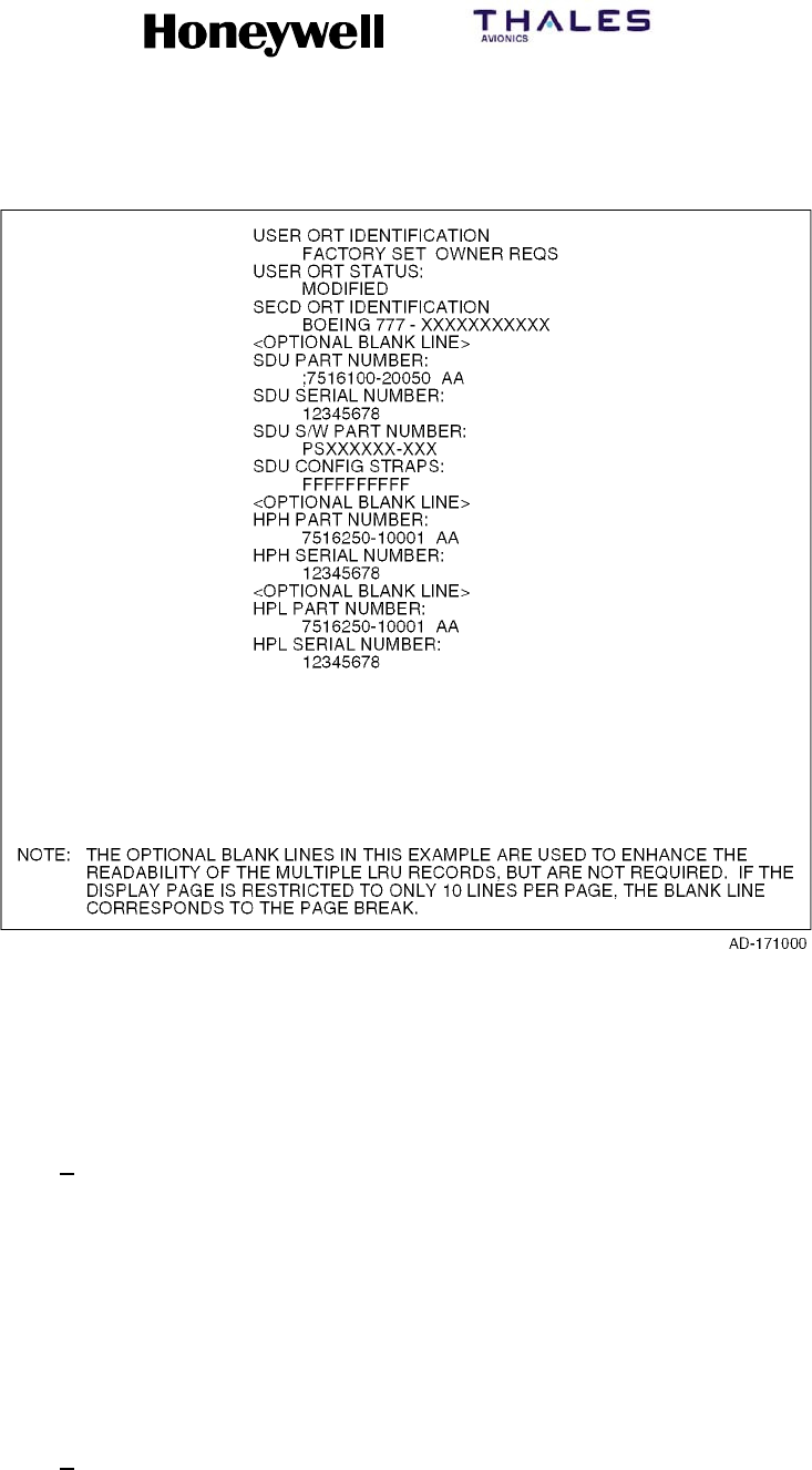
SYSTEM DESCRIPTION, INSTALLATION, AND MAINTENANCE MANUAL
MCS--4200/7200 Multi--Channel SATCOM System
23--20--35 15 Jul 2006
Honeywell International Inc. Do not copy without express permission of Honeywell.
Page 6--92
Figure 6-17. Configuration Data Pages for Boeing 777 Installation
(e) LRU PART NUMBER
1The part numbers for the LRUs installed are displayed as follows. The word
LRU is displayed, which is substituted with the appropriate LRU acronym.
The LRU part number is displayed as bbbbbbb-hhsss, where
bbbbbbb-hhsss represents the LRU end item part number consisting of a
seven-digit LRU base part number (bbbbbbb), a two-digit hardware
configuration number (hh), and a three-digit software configuration number
(sss). Dashes are displayed if no valid data is available.
(f) LRU SERIAL NUMBER
1The serial numbers of the LRUs installed are displayed as follows. The word
LRU is displayed, which is substituted with the appropriate LRU acronym.
The LRU serial number is displayed as ssssssss, where ssssssss represents
the LRU serial number. Dashes are displayed if no valid data is available.

SYSTEM DESCRIPTION, INSTALLATION, AND MAINTENANCE MANUAL
MCS--4200/7200 Multi--Channel SATCOM System
23--20--35 15 Jul 2006
Honeywell International Inc. Do not copy without express permission of Honeywell.
Page 6--93
(g) SDU S/W PART NUMBER
1This displays the software part number that corresponds to the software
load. The configuration data page includes the header SDU CONFIG
STRAPS and the raw strap setting for the current installation.
(5) Standard Ground Test (Non--interactive)
(a) When a standard test on a CMC ground test menu is selected, the CMC
commands the SDU to start a standard ground test. The SDU prevents the CMC
commanded standard ground test while the aircraft is airborne. The SDU starts a
system-wide PAST after it has responded to the receipt of a standard ground test
command from the CMC.
(b) At the end of the CMC-commanded PAST, the SDU builds labels 350 thru 354
fault summary words by mapping PAST-detected SATCOM subsystem failures to
the appropriate bits. The SDU continuously transmits these fault summary words
to the CMC at a rate of 1 to 2 Hz, with the SSM set to Normal Operation, during
reporting of the test results.
C. Airbus/Douglas CFDS
(1) General
(a) The CFDS uses a centralized fault display interface unit (CFDIU) as an interface
between the SDU and the SCDU. Throughout these paragraphs the acronym
CFDIU is used to include both the A320 CFDS and the A340 CMC.
(b) When the SDU is installed on an Airbus or McDonnell Douglas aircraft with a
CFDS, it supports the normal mode and interactive mode as required by the
CFDS.
(2) CFDIU to SDU Communication
(a) The CFDIU communicates with the SDU through an ARINC 429 data bus using
ARINC 429 words.
(3) SDU to CFDIU Communication
(a) The SDU supports both the normal mode and the interactive mode, as required
by the CFDS. The SDU also transmits the LRU part number and serial number
and ORT identification data blocks to the CFDIU.
(b) The LRU/ORT identification data records make up the LRU/ORT identification
data blocks. Each LRU data record contains the LRU acronym, part number, and
serial number. Each ORT identification data record contains the ORT
IDENTIFICATION header, the ORT 24 character description, and the state of the
modified flag.
(4) Normal Mode Failure Messages
(a) As specified, the SDU transmits failure messages and LRU/ORT identification
information while operating in the normal mode. The following paragraphs
defined the contents of these reports.

SYSTEM DESCRIPTION, INSTALLATION, AND MAINTENANCE MANUAL
MCS--4200/7200 Multi--Channel SATCOM System
23--20--35 15 Jul 2006
Honeywell International Inc. Do not copy without express permission of Honeywell.
Page 6--94
(b) Once a failure is reported in the normal mode, the failure remains in the report
for that entire flight, regardless of whether the failure is cleared. As new failures
are reported, they are added to the beginning of the report (i.e., the report is in
reverse chronological order, bearing in mind the CFDS considers the time of the
failure to be the time it is first reported on this flight leg rather than when it first
occurs).
(c) In addition to latching the failures, the contents of the normal mode report
depend on the failure class and when it occurs in relationship to other failures
against the same LRU. Level I failures against the same LRU reported in the
normal mode are not to be transmitted more than once unless they are an upper
class and the upper class failure occurs after the lower class failure(s). Once a
report is sent to the CFDIU during the normal mode for the current flight, the
SDU does not change the content or order except to add new failure messages,
as appropriate to the beginning of the report.
(d) The McDonnell Douglas CFDIU does not decode the normal mode report until
the CFDIU detects an increase in the block word count. However, unlike the
Airbus CFDIU, the McDonnell Douglas CFDIU decodes the entire report. After
sending an All Call DC2 command for a new flight leg, the Airbus CFDIU delays
processing the normal mode report for about 30 seconds before regarding the
report as pertaining to the new flight leg.
(e) The SDU transmits the names of the installed LRUs, as determined by the
system configuration pin settings, along with their associated part/serial
numbers. At the end of this LRU transmission, the SDU transmits the ORT
identification with a modification status. The LRU names can be transmitted in
any order. Transmission of an HPA LRU part/serial number uses the same
criteria as the display of HPA data.
(5) Interactive Mode
(a) The CFDIU supplies for two-way communication between the SCDU and the
SDU, which is referred to as the interactive mode. When the SDU operates in the
interactive mode, it is responsible for all information displayed on the CFDS
maintenance pages, with exception of the scratchpad. The SDU enters the
interactive mode upon receiving an ENQ command from the CFDIU when the
aircraft is on the ground.
D. Central Aircraft Information and Maintenance System
(1) The central aircraft information and maintenance system (CAIMS) is a distributive
maintenance system where each member system performs its own built--in test (BIT)
and stores its own faults. Also, each system supplies real--time status information on
the health of each of its LRUs and their interfaces. The member systems support
CAIMS during normal operation and during on--ground maintenance.

SYSTEM DESCRIPTION, INSTALLATION, AND MAINTENANCE MANUAL
MCS--4200/7200 Multi--Channel SATCOM System
23--20--35 15 Jul 2006
Honeywell International Inc. Do not copy without express permission of Honeywell.
Page 6--95
(2) In the normal operation mode, member systems gather and store fault data when
equipment failure occurs during normal operation. This is typically performed by
continuous BIT and power--up BIT, with identified faults stored in the member
systems non--volatile memory (NVM). The CAIMS does not store fault information for
member systems, but the fault warning processor (FWP) supplies fault event data,
such as: flight leg, date, time, fault zone, and aircraft serial number information that is
stored with the fault in the member systems NVM.
(3) In the maintenance mode, the CAIMS is active and is called the on--board
maintenance system (CAIMS OMS). The CAIMS OMS is the ground maintenance
function and is accessible through communication link to a portable maintenance
access terminal (PMAT). With the PMAT, the aircraft maintenance crew can retrieve
stored fault data from a member system. For member systems, the CAIMS OMS
displays fault information, commands BITE test, and displays real--time data for
status displays, and commands the download of NVM fault data.
E. Level I Failure Messages and ATA Reference Numbers
(1) The Level I failure messages and ATA reference numbers that are available for
transmittal in the CFDS normal mode, for display in the CFDS interactive mode, and
for display on SCDU accessed maintenance pages are specified in the following
paragraphs for each CFDS type installed. Level I failure messages are intended for
use by line maintenance crews. Therefore, the failure messages are designed to be
LRU-based and only supply LRU-level identification.
(2) The Level 1 failure codes are two-digit hexadecimal numbers that define the LRU,
data communication bus, or miscellaneous interface signal where a failure, bus
inactivity, or signal error has been determined to have occurred. When multiple LRUs
are suspect, the most likely LRU is listed first followed by the next most likely LRU,
separated by a slash. The ATA number listed is for the first suspect LRU. Additional
text can be supplied at the end to help clarify the failure message.
•Table 6-18 describes the Level I failure messages and ATA reference numbers to
use for display on the SCDU accessed maintenance pages when the installed
CFDS type is a Boeing CMC. Also shown is the CMC message ID which is
displayed by the CMC in response to the Level I failure messages (refer to the
OEM’s maintenance manual and fault isolation manual).
•Table 6-19 and Table 6-20 describe the Level I failure messages and ATA
reference numbers to use for transmittal in the CFDS normal mode, and the CFDS
interactive mode pages displayed when the installed CFDS type is an Airbus.
Table 6-19 is for the SDU (single configuration) or SDU No. 1 (dual configuration),
and Table 6-20 is for SDU No. 2 (dual configuration) as determined by the settings
of configuration pins TP12E and TP12F.
•Table 6-21 describes the Level I failure messages and ATA reference numbers to
use for transmittal in the CFDS normal mode, and the CFDS interactive mode
pages displayed when the installed CFDS type is a McDonnell Douglas.
•For CFDS type none, the Level I failure messages displayed on the SCDU
accessed maintenance pages are the same as those specified for Boeing (refer to
Table 6-18). However, no ATA reference numbers are displayed.

SYSTEM DESCRIPTION, INSTALLATION, AND MAINTENANCE MANUAL
MCS--4200/7200 Multi--Channel SATCOM System
23--20--35 15 Jul 2006
Honeywell International Inc. Do not copy without express permission of Honeywell.
Page 6--96
(3) For Level I codes identified as not applicable in the tables, the SDU does not report
the failure on that particular interface (i.e., CFDS normal and interactive modes or
SCDU accessed maintenance pages as appropriate). Where TBD is used in the
Level I failure message column, it is coded as literally read. For failures that occur
that are undefined in the tables, the SDU does not report the failure on that particular
interface.
Table 6-18. Boeing Level I Failure Messages and ATA Reference Numbers
Failure
Code SCDU Accessed Maintenance Pages ATA Number
CMC
Message ID
01 SDU 232500 23205
02 OTHER SDU INCOMPATIBILITY 232500 23205
03 HSU 232500
04 HPA--HI GAIN
HPA--HI GAIN
[IGA]
[HGA] 232500 23207
07 HPA--LO GAIN 232500 23209
0A HI POWER RELAY 232500 23218
0D LNA/DIP--(TOP/PORT) 232500 23210
0F LNA/DIP--STBD 232500 23211
10 LNA/DIP--LO GAIN 232500 23212
13 BSU--(TOP/PORT) 232500 23213
15 BSU--STBD 232500 23214
1A IN GAIN ANTENNA--TOP
HI GAIN ANTENNA--(TOP/PORT)
[IGA]
[HGA] 232500 23215
1C HI GAIN ANTENNA--STBD 232500 23216
1F LO GAIN ANTENNA 232500 23225
21 MCDU1 346100
22 MCDU2 346100
23 MCDU3 346100
33 (ACARS MU/CMU)1 232700 23219
34 (ACARS MU/CMU)2 232700 23219
35 IRS--PRI 342100 34222
36 IRS--SEC 342100 34224
37 RESERVED
38 RESERVED

SYSTEM DESCRIPTION, INSTALLATION, AND MAINTENANCE MANUAL
MCS-4200/7200
TEMPORARY REVISION NO. 23-1
23-20-35 Page 43 of 53
28 Sep 2009
© Honeywell International Inc. Do not copy without express permission of Honeywell.
INSERT PAGE 43 OF 53 FACING PAGE 6-96.
Reason: To add a new failure code, 0B, to Table 6-18 between failure codes 0A and 0D.
Failure code 0B is added as follows:
Table 6-18. Boeing Level I Failure Messages and ATA Reference Numbers
Failure
Code SCDU Accessed Maintenance Pages ATA Number CMC
Message ID
0B HDM 232500

SYSTEM DESCRIPTION, INSTALLATION, AND MAINTENANCE MANUAL
MCS--4200/7200 Multi--Channel SATCOM System
23--20--35 15 Jul 2006
Honeywell International Inc. Do not copy without express permission of Honeywell.
Page 6--97
Table 6-18. Boeing Level I Failure Messages and ATA Reference Numbers (cont)
Failure
Code
CMC
Message ID
ATA NumberSCDU Accessed Maintenance Pages
39 RESERVED
3D FMC1 346100
3E FMC2 346100
40 ARINC 429 ICAO ADDRESS None 23251
42 CTU 231900 23235
43 (CFS/CPDF) 233200
50 HSU/SDU 232500
52 (CFS/CPDF)/SDU 233200
53 (ACARS MU/CMU)1/SDU 232700 23219
54 CTU/SDU 231900 23235
55 MCDU1/SDU 346100
56 MCDU2/SDU 346100
57 (ACARS MU/CMU)2/SDU 232700 23235
59 CMC/SDU 454500 23201
5A IRS--PRI/SDU 342100 23222
5B IRS--SEC/SDU 342100 23224
5C HPA--IN GAIN/SDU
HPA--HI GAIN/SDU
[IGA]
[HGA] 232500 23226
5F HPA--LO GAIN/SDU 232500 23225
62 BSU--(TOP/PORT)/SDU 232500 23213
64 BSU--STBD/SDU 232500 23214
66 MCDU3/SDU 346100
67 RESERVED
68 RESERVED
6A RESERVED
6C RESERVED
6D RESERVED
6E RESERVED
6F RESERVED

SYSTEM DESCRIPTION, INSTALLATION, AND MAINTENANCE MANUAL
MCS--4200/7200 Multi--Channel SATCOM System
23--20--35 15 Jul 2006
Honeywell International Inc. Do not copy without express permission of Honeywell.
Page 6--98
Table 6-18. Boeing Level I Failure Messages and ATA Reference Numbers (cont)
Failure
Code
CMC
Message ID
ATA NumberSCDU Accessed Maintenance Pages
71 OTHER SDU/THIS SDU 232500
73 FMC1/SDU 346100
74 FMC2/SDU 346100
80 RESERVED
82 RESERVED
88 RESERVED
90 SDU M--CTRL/HPA--IN GAIN
SDU M--CTRL/HPA--HI GAIN
[IGA]
[HGA] 232500 23246
96 SDU M--CTRL/HPA--LO GAIN 232500 23248
98 SDU M--CTRL/BSU--(TOP/PORT) 232500 23249
9A BSU--STBD XTALK/BSU--PORT 232500 23252
9C SDU M--CTRL/BSU--STBD 232500 23250
9D BSU--PORT XTALK/BSU--STBD 232500 23253
9E SDU/HSU 232500
A6 HSU ETHERNET PORT 1 232500
A7 HSU ETHERNET PORT 2 232500
A8 HSUISDNPORT1 232500
A9 HSUISDNPORT2 232500
C0 WRG:CONFIG PIN PROG/SDU 232500 23236
C1 SDU WOW MISCOMPARE N/A
C2 SDU/OTHER SDU SELECT--DISABLE DISCRETE 232500
C3 WRG:ICAO ADDRESS PIN PROG/SDU 232500 23251
C4 TX PATH VSWR--IN GAIN
TX PATH VSWR--HI GAIN
[IGA]
[HGA] 232500 23257
C5 WRG:CONFIG PIN PROG/SDU OWNER REQS 232500
C6 TX PATH VSWR--LO GAIN 232500 23216
C7 HPA--HI GAIN/OVER TEMPERATURE
HPA--HI GAIN/OVER TEMPERATURE
[IGA]
[HGA] 232500 23247
C8 BAD DATA FROM GROUND EARTH STATION None

SYSTEM DESCRIPTION, INSTALLATION, AND MAINTENANCE MANUAL
MCS--4200/7200 Multi--Channel SATCOM System
23--20--35 15 Jul 2006
Honeywell International Inc. Do not copy without express permission of Honeywell.
Page 6--99
Table 6-18. Boeing Level I Failure Messages and ATA Reference Numbers (cont)
Failure
Code
CMC
Message ID
ATA NumberSCDU Accessed Maintenance Pages
C9 HPA--LO GAIN/OVER TEMPERATURE 232500 23254
CA SDU/LNA/DIP--LO GAIN 232500 23237
CB WRG:SDI PIN PROG/HPA--IN GAIN
WRG:SDI PIN PROG/HPA--HI GAIN
[IGA]
[HGA] 232500
CC WRG:SDI PIN PROG/HPA--HI GAIN 232500
CD SDU (POC/TOTC) DATA RESET None
CE RESERVED
CF HPA--IN GAIN (POC/TOTC) DATA RESET
HPA--HI GAIN (POC/TOTC)DATA RESET
[IGA]
[HGA] None
D0 HPA--LO GAIN (POC/TOTC) DATA RESET None
D1 WRG:SDI PIN PROG/HPA--IN GAIN
WRG:SDI PIN PROG/HPA--HI GAIN
[IGA]
[HGA] 232500
D2 WRG:SDI PIN PROG/HPA--LO GAIN 232500
D3 WRG:SDI PIN PROG/BSU--(TOP/PORT) 232500
D4 WRG:SDI PIN PROG/BSU--STBD 232500
D5 SDU COAX/HPA--IN GAIN
SDU COAX/HPA--HI GAIN
[IGA]
[HGA] 232500 23237
D6 SDU COAX/HPA--LO GAIN 232500 23237
D7 RESERVED
D8 LNA/DIP/ (SDU)--(TOP/PORT) 232500 23236
D9 LNA/DIP/ (SDU)--STBD 232500 23236
DA LNA/DIP/ (SDU)--LO GAIN 232500 23236
DB LO GAIN SUBSYSTEM 232500
DC NO ACTIVE ACARS MU/CMU 232700
DD SDU OWNER REQS -- SECURED None
DE SDU OWNER REQS -- USER None
DF IN GAIN SUBSYSTEM
HI GAIN SUBSYSTEM
[IGA]
[HGA] 232500
E0 RESERVED
E1 BAD HSU DISABLE DISCRETE 232500
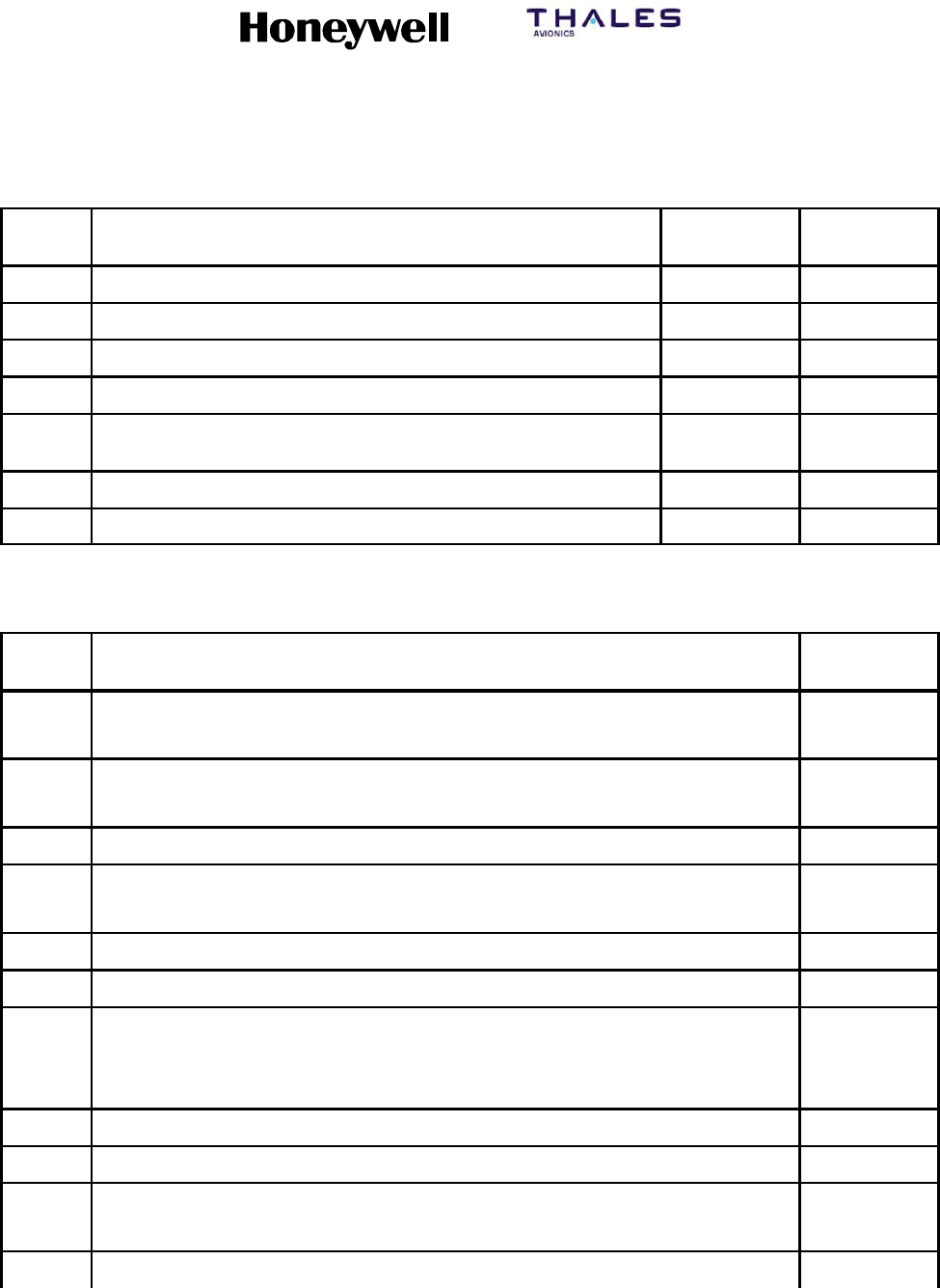
SYSTEM DESCRIPTION, INSTALLATION, AND MAINTENANCE MANUAL
MCS--4200/7200 Multi--Channel SATCOM System
23--20--35 15 Jul 2006
Honeywell International Inc. Do not copy without express permission of Honeywell.
Page 6--100
Table 6-18. Boeing Level I Failure Messages and ATA Reference Numbers (cont)
Failure
Code
CMC
Message ID
ATA NumberSCDU Accessed Maintenance Pages
E4 HSU/SDU INTERFACE VER INCOMPATIBILITY 232500
E6 HSU/HPA TX RF PATH 232500
E8 DLNA/HSU RX RF PATH 232500
EC WRG: CONFIG PIN PROG/HSU 232500
ED WRG: CONFIG PIN PROG/HSU
SDU OWNER REQS
232500
EE WRG: FWD ID PIN PROG/HSU 232500
FE POWER SUPPLY INTERRUPT None
Table 6-19. Airbus Level I (SDU No. 1) Failure Messages and ATA No.
Failure
Code SDU/SDU No. 1 -- CFDS Normal and Interactive Modes ATA Number
01 SDU1(105RV1)
SDU1(5RV1)
[IGA]
[HGA]
232834
232834
02 SDU2(105RV2)
SDU2(5RV2) INCOMPATIBILITY
[IGA]
[HGA]
232834
232834
03 HSDU1 (63RV1) 232839
04 HPA1(110RV1)
HPA--HI GAIN(7RV1)
[IGA]
[HGA]
232831
232831
07 HPA--LO GAIN(9RV) 232835
0A HI POWER RELAY(21RV) 232842
0D DLNA1(119RV1)
DLNA--TOP(19RV1)
DLNA--L(20RV1)
[IGA]
[Top Mount]
[Conformal]
232838
232838
232837
0F DLNA--R(20RV2) [Conformal] 232837
10 DLNA--LO GAIN(14RV) 232836
13 BSU(8RV1)
BSU--L(15RV1)
[Top Mount]
[Conformal]
232846
232844
15 BSU--R(15RV2) [Conformal] 232844