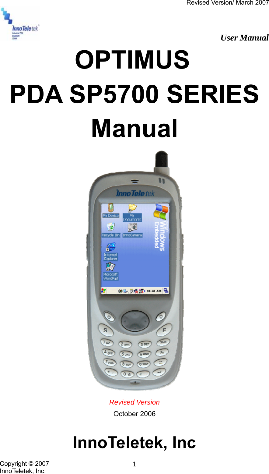
Honeywell SP5700 PDA with Bluetooth, WLAN and GSM Modules User Manual
Honeywell International Inc. PDA with Bluetooth, WLAN and GSM Modules
UserManual.wiki
>
Honeywell
>
SP5700 User Manual
>
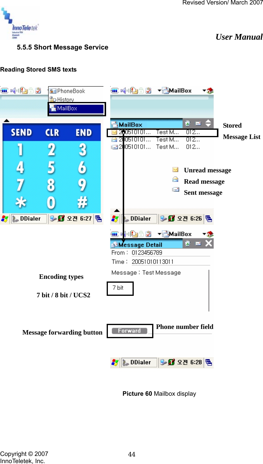
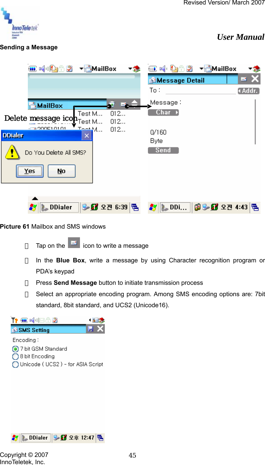
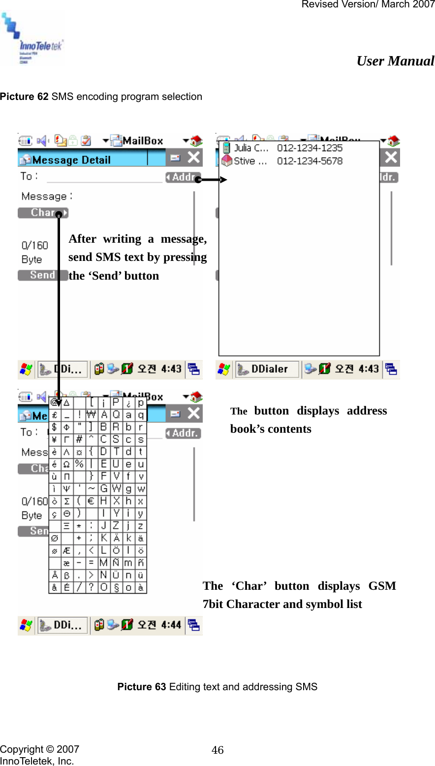
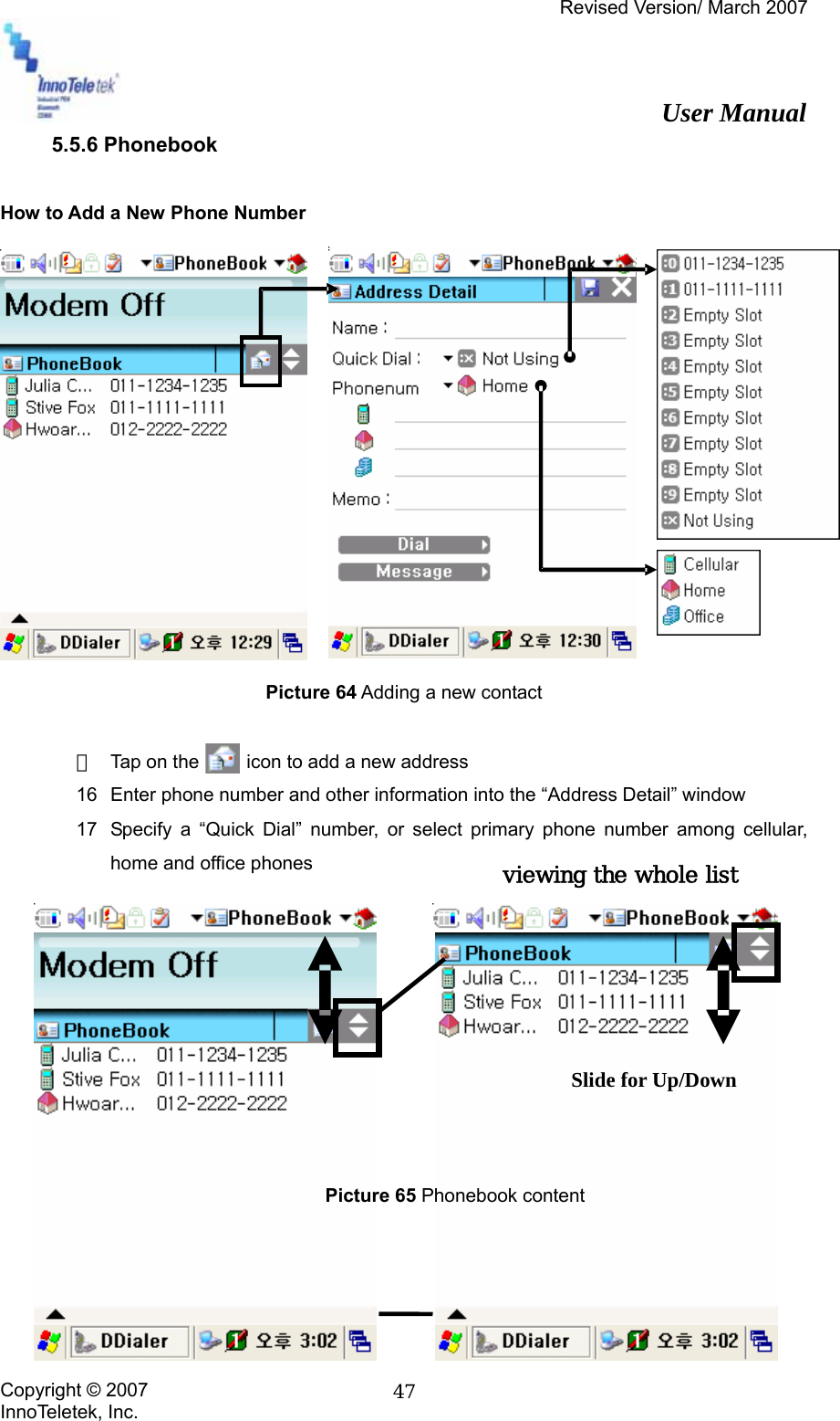
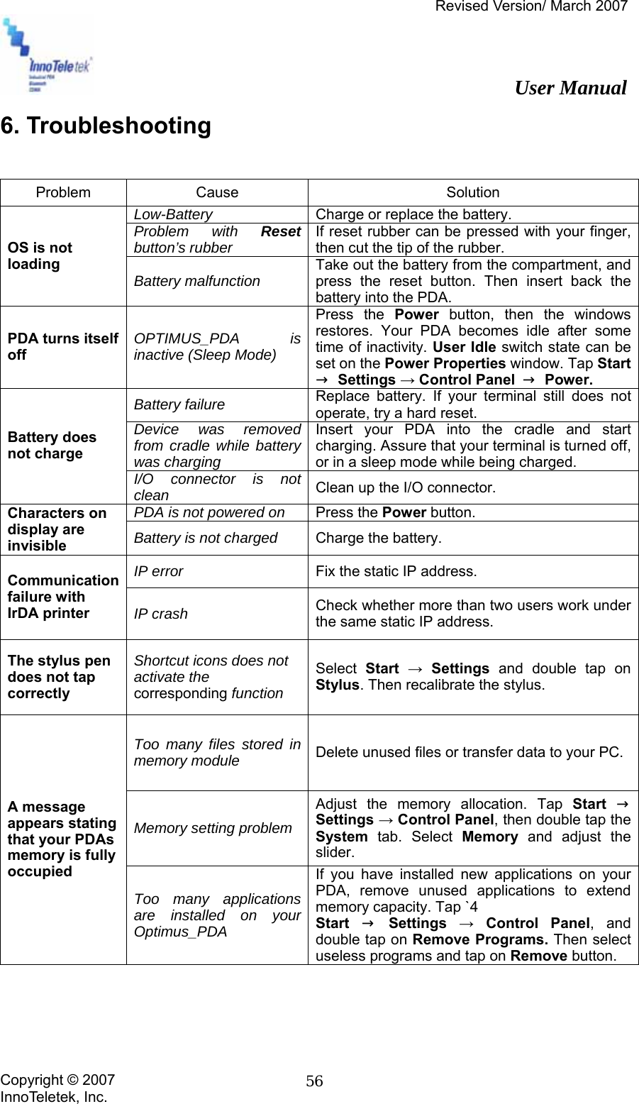
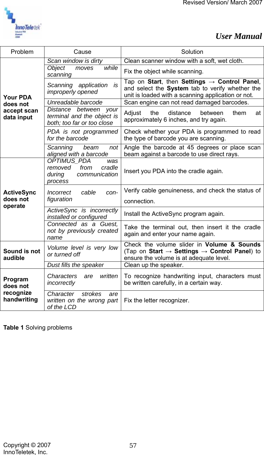
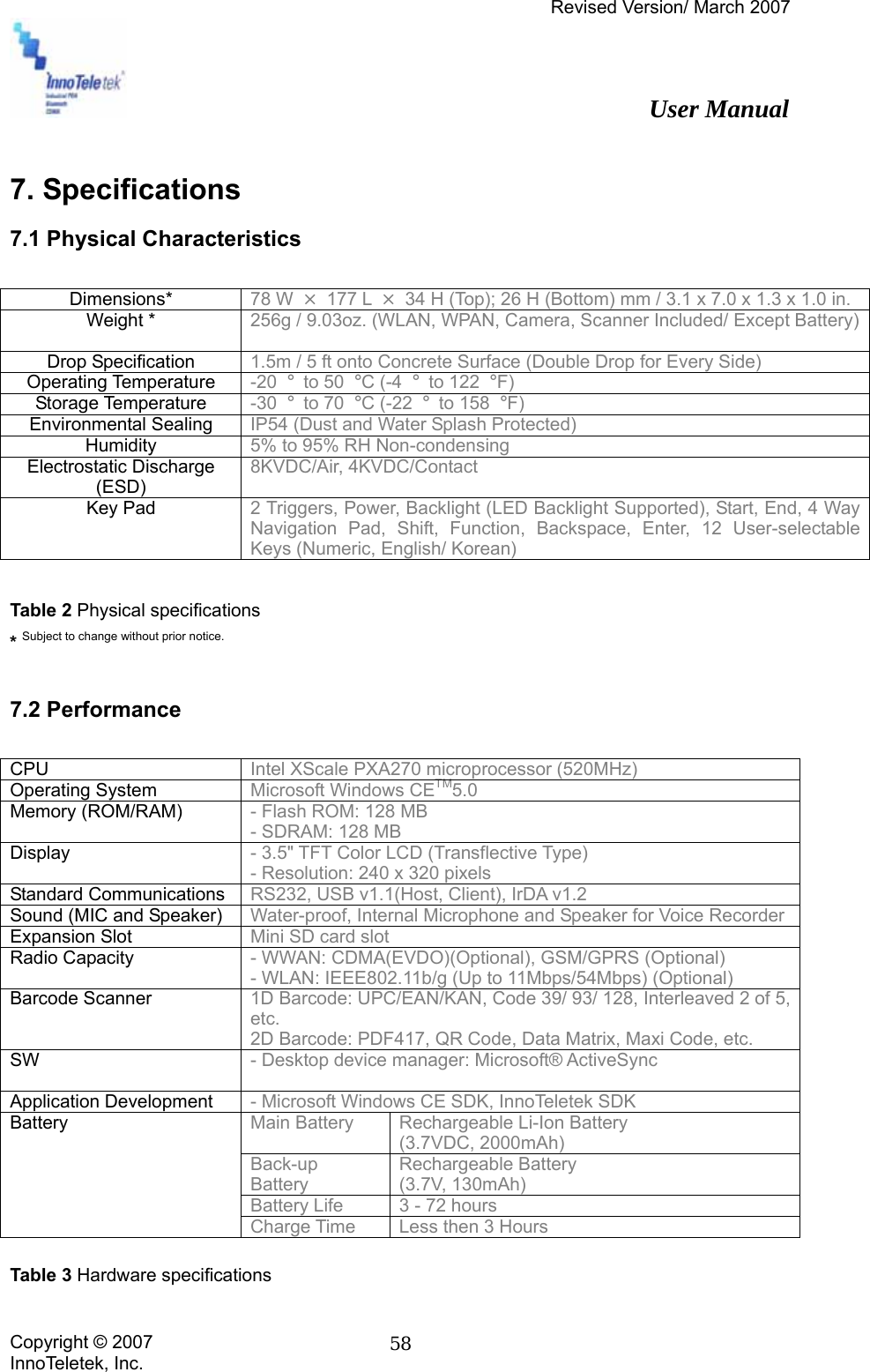
Users Manual
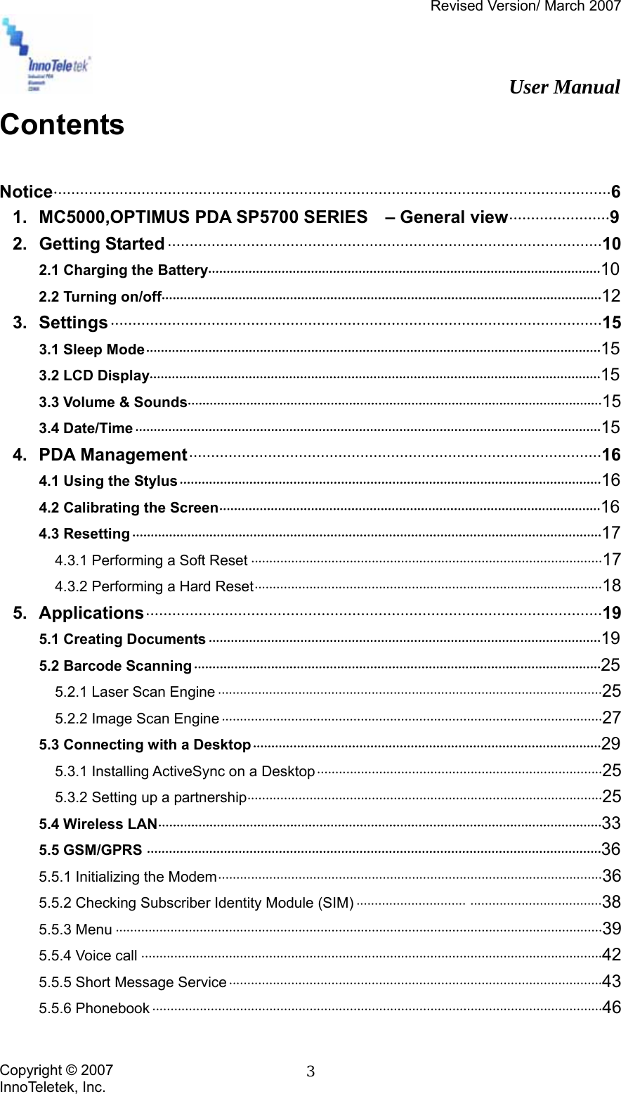
Contents
1.
Users Manual
2.
Manual
Users Manual
Navigation menu
Upload a User Manual
Namespaces
Wiki Guide
HTML
PDF
Info
Views
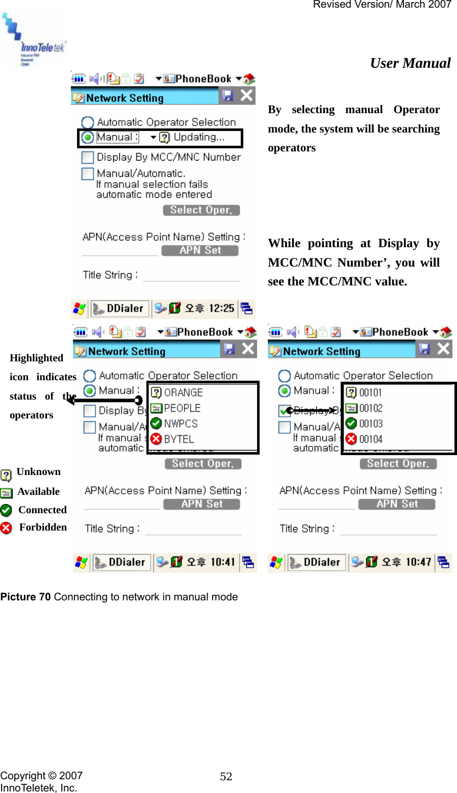
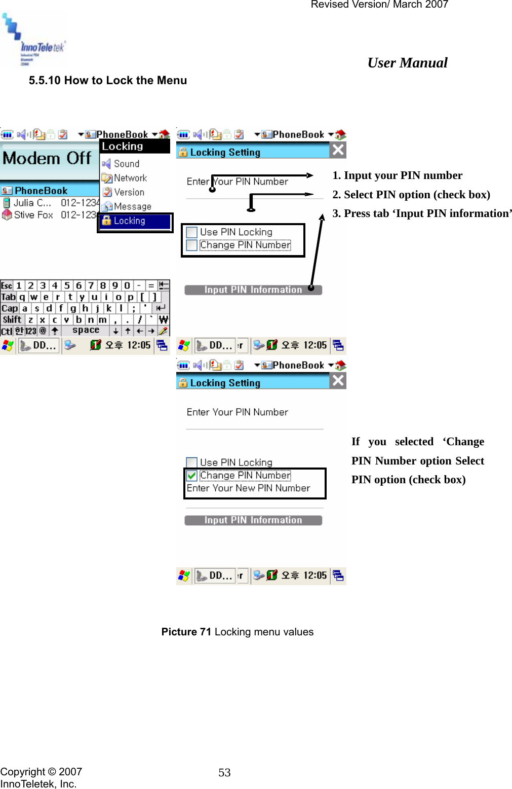
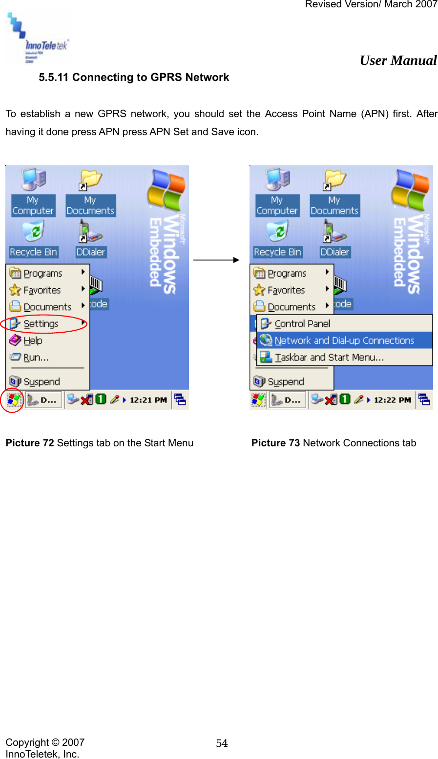
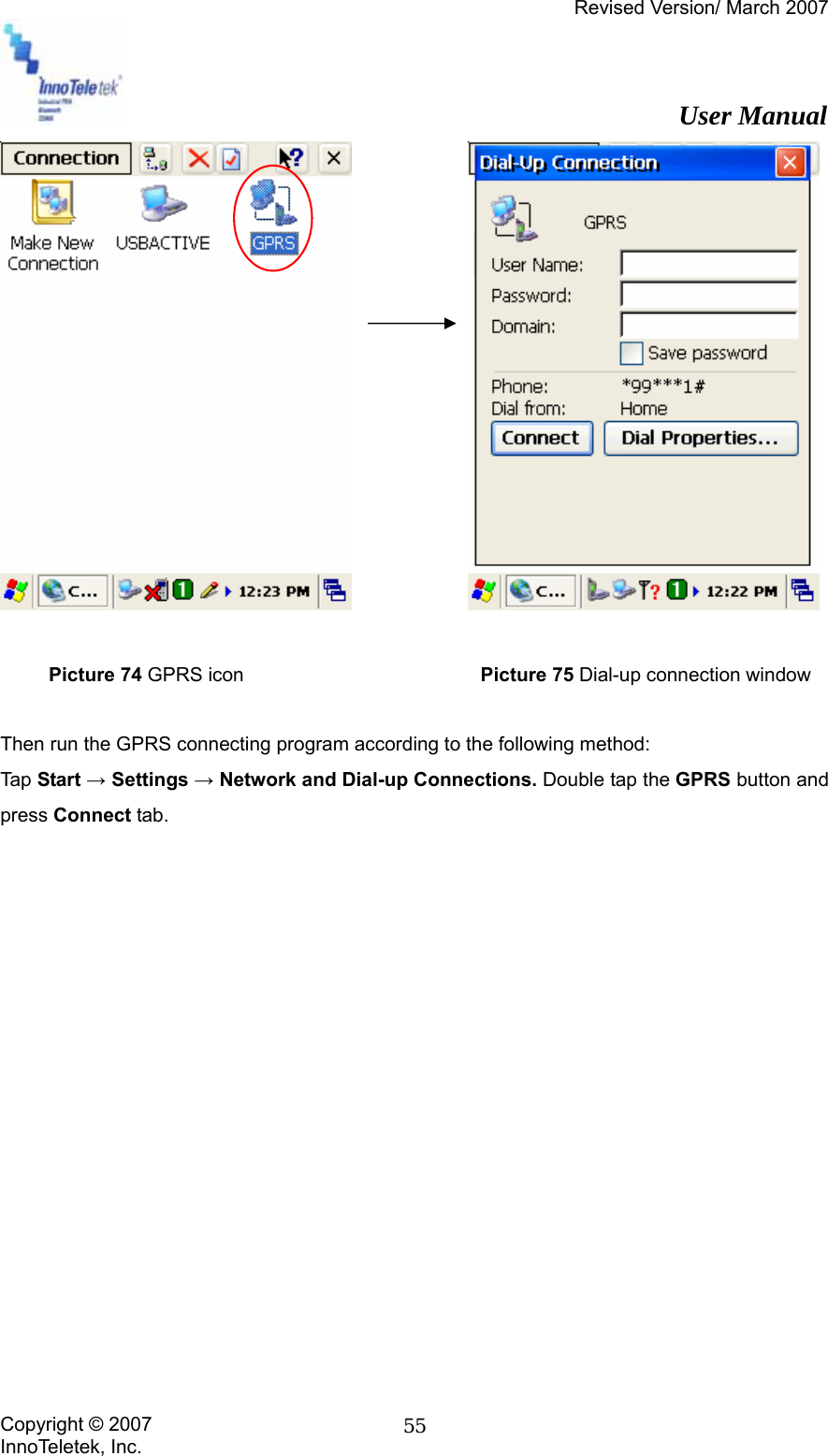
User Manual
Discussion / Help
Navigation