Honeywell SP5700 PDA with Bluetooth, WLAN and GSM Modules User Manual
Honeywell International Inc. PDA with Bluetooth, WLAN and GSM Modules
Contents
- 1. Users Manual
- 2. Manual
Users Manual
Revised Version/ March 2007
User Manual
Copyright © 2007
InnoTeletek, Inc. 1
OPTIMUS
PDA SP5700 SERIES
Manual
Revised Version
October 2006
InnoTeletek, Inc

Revised Version/ March 2007
User Manual
Copyright © 2007
InnoTeletek, Inc. 2
FCC Statement
This device complies with part 15 of the FCC Rules. Operation
is subject to the following two conditions:
(1) This device may not cause harmful interference, and
(2) This device must accept any interference received,
including interference that may cause undesired operation.
Caution: Any changes or modifications to the equipment not expressly approved by the
party responsible for compliance could void user’s authority to operate the equipment.
FCC Compliance statement
This equipment has been tested and found to comply with the limits for a Class B
digital device, pursuant to part 15 of the FCC Rules. These limits are designed to
provide reasonable protection against harmful interference in a residential installation.
This equipment generates, uses and can radiate radio frequency energy and, if not
installed and used in accordance with the instructions, may cause harmful interference
to radio communications. However, there is no guarantee that interference will not
occur in a particular installation. If this equipment does cause harmful interference to
radio or television reception, which can be determined by turning the equipment off and
on, the user is encouraged to try to correct the interference by one or more of the
following measures:
- Reorient or relocate the receiving antenna.
- Increase the separation between the equipment and receiver.
- Connect the equipment into an outlet on a circuit different from that to which the
receiver is connected.
- Consult the dealer or an experienced radio/TV technician for help.

Preliminary Version / January 2005
2
FCC RF EXPOSURE INFORMATION
WARNING! Read this information before using your phone
In August 1996 the Federal Communications Commission (FCC) of the United States
with its action in Report and Order FCC 96-326 adopted an updated safety standard for human
exposure to radio frequency (RF) electromagnetic energy emitted by FCC regulated transmitters.
Those guidelines are consistent with the safety standard previously set by both U.S. and
international standards bodies. The design of this phone complies with the FCC guidelines and
these international standards.
Use only the supplied or an approved antenna. Unauthorized antennas,
modifications, or attachments could impair call quality, damage the phone, or result in violation
of FCC regulations.
Do not use the phone with a damaged antenna. If a damaged antenna comes into
contact with the skin, a minor burn may result. Please contact your local dealer for replacement
antenna.
Body-worn Operation
This device was tested for typical body-worn operations with the back of the phone
kept 0.59 inches (1.5 cm) from the body. To comply with FCC RF exposure requirements, a
minimum separation distance of 0.59 inches (1.5 cm) must be maintained between the user’s
body and the back of the phone, including the antenna, whether extended or retracted. Third-
party belt-clips, holsters and similar accessories should not contain metallic components and
must provide 0.59 inch (1.5 cm) separation distance between the user’s body and the back of
the phone. Body-worn accessories that do not meet these requirements may not comply with
FCC RF exposure limits and should be avoided.
For more information about RF exposure, please visit the FCC website at www.fcc.gov

Revised Version/ March 2007
User Manual
Copyright © 2007
InnoTeletek, Inc. 3
Contents
Notice⋅⋅⋅⋅⋅⋅⋅⋅⋅⋅⋅⋅⋅⋅⋅⋅⋅⋅⋅⋅⋅⋅⋅⋅⋅⋅⋅⋅⋅⋅⋅⋅⋅⋅⋅⋅⋅⋅⋅⋅⋅⋅⋅⋅⋅⋅⋅⋅⋅⋅⋅⋅⋅⋅⋅⋅⋅⋅⋅⋅⋅⋅⋅⋅⋅⋅⋅⋅⋅⋅⋅⋅⋅⋅⋅⋅⋅⋅⋅⋅⋅⋅⋅⋅⋅⋅⋅⋅⋅⋅⋅⋅⋅⋅⋅⋅⋅⋅⋅⋅⋅⋅⋅⋅⋅⋅⋅⋅⋅⋅⋅⋅⋅⋅⋅⋅⋅⋅⋅⋅⋅⋅⋅⋅⋅⋅⋅6
1. MC5000,OPTIMUS PDA SP5700 SERIES – General view ⋅⋅⋅⋅⋅⋅⋅⋅⋅⋅⋅⋅⋅⋅⋅⋅⋅⋅⋅⋅⋅⋅⋅9
2. Getting Started ⋅⋅⋅⋅⋅⋅⋅⋅⋅⋅⋅⋅⋅⋅⋅⋅⋅⋅⋅⋅⋅⋅⋅⋅⋅⋅⋅⋅⋅⋅⋅⋅⋅⋅⋅⋅⋅⋅⋅⋅⋅⋅⋅⋅⋅⋅⋅⋅⋅⋅⋅⋅⋅⋅⋅⋅⋅⋅⋅⋅⋅⋅⋅⋅⋅⋅⋅⋅⋅⋅⋅⋅⋅⋅⋅⋅⋅⋅⋅⋅⋅⋅⋅⋅⋅⋅⋅⋅⋅⋅⋅⋅⋅⋅⋅⋅⋅⋅⋅10
2.1 Charging the Battery⋅⋅⋅⋅⋅⋅⋅⋅⋅⋅⋅⋅⋅⋅⋅⋅⋅⋅⋅⋅⋅⋅⋅⋅⋅⋅⋅⋅⋅⋅⋅⋅⋅⋅⋅⋅⋅⋅⋅⋅⋅⋅⋅⋅⋅⋅⋅⋅⋅⋅⋅⋅⋅⋅⋅⋅⋅⋅⋅⋅⋅⋅⋅⋅⋅⋅⋅⋅⋅⋅⋅⋅⋅⋅⋅⋅⋅⋅⋅⋅⋅⋅⋅⋅⋅⋅⋅⋅⋅⋅⋅⋅⋅⋅⋅⋅⋅⋅⋅⋅⋅⋅⋅⋅⋅⋅⋅10
2.2 Turning on/off⋅⋅⋅⋅⋅⋅⋅⋅⋅⋅⋅⋅⋅⋅⋅⋅⋅⋅⋅⋅⋅⋅⋅⋅⋅⋅⋅⋅⋅⋅⋅⋅⋅⋅⋅⋅⋅⋅⋅⋅⋅⋅⋅⋅⋅⋅⋅⋅⋅⋅⋅⋅⋅⋅⋅⋅⋅⋅⋅⋅⋅⋅⋅⋅⋅⋅⋅⋅⋅⋅⋅⋅⋅⋅⋅⋅⋅⋅⋅⋅⋅⋅⋅⋅⋅⋅⋅⋅⋅⋅⋅⋅⋅⋅⋅⋅⋅⋅⋅⋅⋅⋅⋅⋅⋅⋅⋅⋅⋅⋅⋅⋅⋅⋅⋅⋅⋅⋅⋅⋅12
3. Settings ⋅⋅⋅⋅⋅⋅⋅⋅⋅⋅⋅⋅⋅⋅⋅⋅⋅⋅⋅⋅⋅⋅⋅⋅⋅⋅⋅⋅⋅⋅⋅⋅⋅⋅⋅⋅⋅⋅⋅⋅⋅⋅⋅⋅⋅⋅⋅⋅⋅⋅⋅⋅⋅⋅⋅⋅⋅⋅⋅⋅⋅⋅⋅⋅⋅⋅⋅⋅⋅⋅⋅⋅⋅⋅⋅⋅⋅⋅⋅⋅⋅⋅⋅⋅⋅⋅⋅⋅⋅⋅⋅⋅⋅⋅⋅⋅⋅⋅⋅⋅⋅⋅⋅⋅⋅⋅⋅⋅⋅⋅⋅⋅15
3.1 Sleep Mode ⋅⋅⋅⋅⋅⋅⋅⋅⋅⋅⋅⋅⋅⋅⋅⋅⋅⋅⋅⋅⋅⋅⋅⋅⋅⋅⋅⋅⋅⋅⋅⋅⋅⋅⋅⋅⋅⋅⋅⋅⋅⋅⋅⋅⋅⋅⋅⋅⋅⋅⋅⋅⋅⋅⋅⋅⋅⋅⋅⋅⋅⋅⋅⋅⋅⋅⋅⋅⋅⋅⋅⋅⋅⋅⋅⋅⋅⋅⋅⋅⋅⋅⋅⋅⋅⋅⋅⋅⋅⋅⋅⋅⋅⋅⋅⋅⋅⋅⋅⋅⋅⋅⋅⋅⋅⋅⋅⋅⋅⋅⋅⋅⋅⋅⋅⋅⋅⋅⋅⋅⋅⋅⋅⋅15
3.2 LCD Display⋅⋅⋅⋅⋅⋅⋅⋅⋅⋅⋅⋅⋅⋅⋅⋅⋅⋅⋅⋅⋅⋅⋅⋅⋅⋅⋅⋅⋅⋅⋅⋅⋅⋅⋅⋅⋅⋅⋅⋅⋅⋅⋅⋅⋅⋅⋅⋅⋅⋅⋅⋅⋅⋅⋅⋅⋅⋅⋅⋅⋅⋅⋅⋅⋅⋅⋅⋅⋅⋅⋅⋅⋅⋅⋅⋅⋅⋅⋅⋅⋅⋅⋅⋅⋅⋅⋅⋅⋅⋅⋅⋅⋅⋅⋅⋅⋅⋅⋅⋅⋅⋅⋅⋅⋅⋅⋅⋅⋅⋅⋅⋅⋅⋅⋅⋅⋅⋅⋅⋅⋅⋅⋅15
3.3 Volume & Sounds⋅⋅⋅⋅⋅⋅⋅⋅⋅⋅⋅⋅⋅⋅⋅⋅⋅⋅⋅⋅⋅⋅⋅⋅⋅⋅⋅⋅⋅⋅⋅⋅⋅⋅⋅⋅⋅⋅⋅⋅⋅⋅⋅⋅⋅⋅⋅⋅⋅⋅⋅⋅⋅⋅⋅⋅⋅⋅⋅⋅⋅⋅⋅⋅⋅⋅⋅⋅⋅⋅⋅⋅⋅⋅⋅⋅⋅⋅⋅⋅⋅⋅⋅⋅⋅⋅⋅⋅⋅⋅⋅⋅⋅⋅⋅⋅⋅⋅⋅⋅⋅⋅⋅⋅⋅⋅⋅⋅⋅⋅⋅⋅⋅15
3.4 Date/Time ⋅⋅⋅⋅⋅⋅⋅⋅⋅⋅⋅⋅⋅⋅⋅⋅⋅⋅⋅⋅⋅⋅⋅⋅⋅⋅⋅⋅⋅⋅⋅⋅⋅⋅⋅⋅⋅⋅⋅⋅⋅⋅⋅⋅⋅⋅⋅⋅⋅⋅⋅⋅⋅⋅⋅⋅⋅⋅⋅⋅⋅⋅⋅⋅⋅⋅⋅⋅⋅⋅⋅⋅⋅⋅⋅⋅⋅⋅⋅⋅⋅⋅⋅⋅⋅⋅⋅⋅⋅⋅⋅⋅⋅⋅⋅⋅⋅⋅⋅⋅⋅⋅⋅⋅⋅⋅⋅⋅⋅⋅⋅⋅⋅⋅⋅⋅⋅⋅⋅⋅⋅⋅⋅⋅⋅⋅⋅15
4. PDA Management ⋅⋅⋅⋅⋅⋅⋅⋅⋅⋅⋅⋅⋅⋅⋅⋅⋅⋅⋅⋅⋅⋅⋅⋅⋅⋅⋅⋅⋅⋅⋅⋅⋅⋅⋅⋅⋅⋅⋅⋅⋅⋅⋅⋅⋅⋅⋅⋅⋅⋅⋅⋅⋅⋅⋅⋅⋅⋅⋅⋅⋅⋅⋅⋅⋅⋅⋅⋅⋅⋅⋅⋅⋅⋅⋅⋅⋅⋅⋅⋅⋅⋅⋅⋅⋅⋅⋅⋅⋅⋅⋅⋅⋅⋅16
4.1 Using the Stylus ⋅⋅⋅⋅⋅⋅⋅⋅⋅⋅⋅⋅⋅⋅⋅⋅⋅⋅⋅⋅⋅⋅⋅⋅⋅⋅⋅⋅⋅⋅⋅⋅⋅⋅⋅⋅⋅⋅⋅⋅⋅⋅⋅⋅⋅⋅⋅⋅⋅⋅⋅⋅⋅⋅⋅⋅⋅⋅⋅⋅⋅⋅⋅⋅⋅⋅⋅⋅⋅⋅⋅⋅⋅⋅⋅⋅⋅⋅⋅⋅⋅⋅⋅⋅⋅⋅⋅⋅⋅⋅⋅⋅⋅⋅⋅⋅⋅⋅⋅⋅⋅⋅⋅⋅⋅⋅⋅⋅⋅⋅⋅⋅⋅⋅⋅16
4.2 Calibrating the Screen ⋅⋅⋅⋅⋅⋅⋅⋅⋅⋅⋅⋅⋅⋅⋅⋅⋅⋅⋅⋅⋅⋅⋅⋅⋅⋅⋅⋅⋅⋅⋅⋅⋅⋅⋅⋅⋅⋅⋅⋅⋅⋅⋅⋅⋅⋅⋅⋅⋅⋅⋅⋅⋅⋅⋅⋅⋅⋅⋅⋅⋅⋅⋅⋅⋅⋅⋅⋅⋅⋅⋅⋅⋅⋅⋅⋅⋅⋅⋅⋅⋅⋅⋅⋅⋅⋅⋅⋅⋅⋅⋅⋅⋅⋅⋅⋅⋅⋅⋅⋅⋅⋅⋅⋅16
4.3 Resetting ⋅⋅⋅⋅⋅⋅⋅⋅⋅⋅⋅⋅⋅⋅⋅⋅⋅⋅⋅⋅⋅⋅⋅⋅⋅⋅⋅⋅⋅⋅⋅⋅⋅⋅⋅⋅⋅⋅⋅⋅⋅⋅⋅⋅⋅⋅⋅⋅⋅⋅⋅⋅⋅⋅⋅⋅⋅⋅⋅⋅⋅⋅⋅⋅⋅⋅⋅⋅⋅⋅⋅⋅⋅⋅⋅⋅⋅⋅⋅⋅⋅⋅⋅⋅⋅⋅⋅⋅⋅⋅⋅⋅⋅⋅⋅⋅⋅⋅⋅⋅⋅⋅⋅⋅⋅⋅⋅⋅⋅⋅⋅⋅⋅⋅⋅⋅⋅⋅⋅⋅⋅⋅⋅⋅⋅⋅⋅⋅17
4.3.1 Performing a Soft Reset ⋅⋅⋅⋅⋅⋅⋅⋅⋅⋅⋅⋅⋅⋅⋅⋅⋅⋅⋅⋅⋅⋅⋅⋅⋅⋅⋅⋅⋅⋅⋅⋅⋅⋅⋅⋅⋅⋅⋅⋅⋅⋅⋅⋅⋅⋅⋅⋅⋅⋅⋅⋅⋅⋅⋅⋅⋅⋅⋅⋅⋅⋅⋅⋅⋅⋅⋅⋅⋅⋅⋅⋅⋅⋅⋅⋅⋅⋅⋅⋅⋅⋅⋅⋅⋅⋅⋅⋅⋅⋅⋅⋅⋅⋅⋅⋅17
4.3.2 Performing a Hard Reset ⋅⋅⋅⋅⋅⋅⋅⋅⋅⋅⋅⋅⋅⋅⋅⋅⋅⋅⋅⋅⋅⋅⋅⋅⋅⋅⋅⋅⋅⋅⋅⋅⋅⋅⋅⋅⋅⋅⋅⋅⋅⋅⋅⋅⋅⋅⋅⋅⋅⋅⋅⋅⋅⋅⋅⋅⋅⋅⋅⋅⋅⋅⋅⋅⋅⋅⋅⋅⋅⋅⋅⋅⋅⋅⋅⋅⋅⋅⋅⋅⋅⋅⋅⋅⋅⋅⋅⋅⋅⋅⋅⋅⋅⋅⋅18
5. Applications ⋅⋅⋅⋅⋅⋅⋅⋅⋅⋅⋅⋅⋅⋅⋅⋅⋅⋅⋅⋅⋅⋅⋅⋅⋅⋅⋅⋅⋅⋅⋅⋅⋅⋅⋅⋅⋅⋅⋅⋅⋅⋅⋅⋅⋅⋅⋅⋅⋅⋅⋅⋅⋅⋅⋅⋅⋅⋅⋅⋅⋅⋅⋅⋅⋅⋅⋅⋅⋅⋅⋅⋅⋅⋅⋅⋅⋅⋅⋅⋅⋅⋅⋅⋅⋅⋅⋅⋅⋅⋅⋅⋅⋅⋅⋅⋅⋅⋅⋅⋅⋅⋅⋅⋅19
5.1 Creating Documents ⋅⋅⋅⋅⋅⋅⋅⋅⋅⋅⋅⋅⋅⋅⋅⋅⋅⋅⋅⋅⋅⋅⋅⋅⋅⋅⋅⋅⋅⋅⋅⋅⋅⋅⋅⋅⋅⋅⋅⋅⋅⋅⋅⋅⋅⋅⋅⋅⋅⋅⋅⋅⋅⋅⋅⋅⋅⋅⋅⋅⋅⋅⋅⋅⋅⋅⋅⋅⋅⋅⋅⋅⋅⋅⋅⋅⋅⋅⋅⋅⋅⋅⋅⋅⋅⋅⋅⋅⋅⋅⋅⋅⋅⋅⋅⋅⋅⋅⋅⋅⋅⋅⋅⋅⋅⋅⋅19
5.2 Barcode Scanning ⋅⋅⋅⋅⋅⋅⋅⋅⋅⋅⋅⋅⋅⋅⋅⋅⋅⋅⋅⋅⋅⋅⋅⋅⋅⋅⋅⋅⋅⋅⋅⋅⋅⋅⋅⋅⋅⋅⋅⋅⋅⋅⋅⋅⋅⋅⋅⋅⋅⋅⋅⋅⋅⋅⋅⋅⋅⋅⋅⋅⋅⋅⋅⋅⋅⋅⋅⋅⋅⋅⋅⋅⋅⋅⋅⋅⋅⋅⋅⋅⋅⋅⋅⋅⋅⋅⋅⋅⋅⋅⋅⋅⋅⋅⋅⋅⋅⋅⋅⋅⋅⋅⋅⋅⋅⋅⋅⋅⋅⋅⋅25
5.2.1 Laser Scan Engine ⋅⋅⋅⋅⋅⋅⋅⋅⋅⋅⋅⋅⋅⋅⋅⋅⋅⋅⋅⋅⋅⋅⋅⋅⋅⋅⋅⋅⋅⋅⋅⋅⋅⋅⋅⋅⋅⋅⋅⋅⋅⋅⋅⋅⋅⋅⋅⋅⋅⋅⋅⋅⋅⋅⋅⋅⋅⋅⋅⋅⋅⋅⋅⋅⋅⋅⋅⋅⋅⋅⋅⋅⋅⋅⋅⋅⋅⋅⋅⋅⋅⋅⋅⋅⋅⋅⋅⋅⋅⋅⋅⋅⋅⋅⋅⋅⋅⋅⋅⋅⋅⋅⋅⋅⋅25
5.2.2 Image Scan Engine ⋅⋅⋅⋅⋅⋅⋅⋅⋅⋅⋅⋅⋅⋅⋅⋅⋅⋅⋅⋅⋅⋅⋅⋅⋅⋅⋅⋅⋅⋅⋅⋅⋅⋅⋅⋅⋅⋅⋅⋅⋅⋅⋅⋅⋅⋅⋅⋅⋅⋅⋅⋅⋅⋅⋅⋅⋅⋅⋅⋅⋅⋅⋅⋅⋅⋅⋅⋅⋅⋅⋅⋅⋅⋅⋅⋅⋅⋅⋅⋅⋅⋅⋅⋅⋅⋅⋅⋅⋅⋅⋅⋅⋅⋅⋅⋅⋅⋅⋅⋅⋅⋅⋅⋅27
5.3 Connecting with a Desktop ⋅⋅⋅⋅⋅⋅⋅⋅⋅⋅⋅⋅⋅⋅⋅⋅⋅⋅⋅⋅⋅⋅⋅⋅⋅⋅⋅⋅⋅⋅⋅⋅⋅⋅⋅⋅⋅⋅⋅⋅⋅⋅⋅⋅⋅⋅⋅⋅⋅⋅⋅⋅⋅⋅⋅⋅⋅⋅⋅⋅⋅⋅⋅⋅⋅⋅⋅⋅⋅⋅⋅⋅⋅⋅⋅⋅⋅⋅⋅⋅⋅⋅⋅⋅⋅⋅⋅⋅⋅⋅⋅⋅⋅⋅⋅29
5.3.1 Installing ActiveSync on a Desktop ⋅⋅⋅⋅⋅⋅⋅⋅⋅⋅⋅⋅⋅⋅⋅⋅⋅⋅⋅⋅⋅⋅⋅⋅⋅⋅⋅⋅⋅⋅⋅⋅⋅⋅⋅⋅⋅⋅⋅⋅⋅⋅⋅⋅⋅⋅⋅⋅⋅⋅⋅⋅⋅⋅⋅⋅⋅⋅⋅⋅⋅⋅⋅⋅⋅⋅⋅⋅⋅⋅⋅⋅⋅⋅⋅⋅⋅⋅25
5.3.2 Setting up a partnership ⋅⋅⋅⋅⋅⋅⋅⋅⋅⋅⋅⋅⋅⋅⋅⋅⋅⋅⋅⋅⋅⋅⋅⋅⋅⋅⋅⋅⋅⋅⋅⋅⋅⋅⋅⋅⋅⋅⋅⋅⋅⋅⋅⋅⋅⋅⋅⋅⋅⋅⋅⋅⋅⋅⋅⋅⋅⋅⋅⋅⋅⋅⋅⋅⋅⋅⋅⋅⋅⋅⋅⋅⋅⋅⋅⋅⋅⋅⋅⋅⋅⋅⋅⋅⋅⋅⋅⋅⋅⋅⋅⋅⋅⋅⋅⋅⋅25
5.4 Wireless LAN ⋅⋅⋅⋅⋅⋅⋅⋅⋅⋅⋅⋅⋅⋅⋅⋅⋅⋅⋅⋅⋅⋅⋅⋅⋅⋅⋅⋅⋅⋅⋅⋅⋅⋅⋅⋅⋅⋅⋅⋅⋅⋅⋅⋅⋅⋅⋅⋅⋅⋅⋅⋅⋅⋅⋅⋅⋅⋅⋅⋅⋅⋅⋅⋅⋅⋅⋅⋅⋅⋅⋅⋅⋅⋅⋅⋅⋅⋅⋅⋅⋅⋅⋅⋅⋅⋅⋅⋅⋅⋅⋅⋅⋅⋅⋅⋅⋅⋅⋅⋅⋅⋅⋅⋅⋅⋅⋅⋅⋅⋅⋅⋅⋅⋅⋅⋅⋅⋅⋅⋅⋅33
5.5 GSM/GPRS ⋅⋅⋅⋅⋅⋅⋅⋅⋅⋅⋅⋅⋅⋅⋅⋅⋅⋅⋅⋅⋅⋅⋅⋅⋅⋅⋅⋅⋅⋅⋅⋅⋅⋅⋅⋅⋅⋅⋅⋅⋅⋅⋅⋅⋅⋅⋅⋅⋅⋅⋅⋅⋅⋅⋅⋅⋅⋅⋅⋅⋅⋅⋅⋅⋅⋅⋅⋅⋅⋅⋅⋅⋅⋅⋅⋅⋅⋅⋅⋅⋅⋅⋅⋅⋅⋅⋅⋅⋅⋅⋅⋅⋅⋅⋅⋅⋅⋅⋅⋅⋅⋅⋅⋅⋅⋅⋅⋅⋅⋅⋅⋅⋅⋅⋅⋅⋅⋅⋅⋅⋅⋅⋅⋅36
5.5.1 Initializing the Modem ⋅⋅⋅⋅⋅⋅⋅⋅⋅⋅⋅⋅⋅⋅⋅⋅⋅⋅⋅⋅⋅⋅⋅⋅⋅⋅⋅⋅⋅⋅⋅⋅⋅⋅⋅⋅⋅⋅⋅⋅⋅⋅⋅⋅⋅⋅⋅⋅⋅⋅⋅⋅⋅⋅⋅⋅⋅⋅⋅⋅⋅⋅⋅⋅⋅⋅⋅⋅⋅⋅⋅⋅⋅⋅⋅⋅⋅⋅⋅⋅⋅⋅⋅⋅⋅⋅⋅⋅⋅⋅⋅⋅⋅⋅⋅⋅⋅⋅⋅⋅⋅⋅⋅⋅⋅36
5.5.2 Checking Subscriber Identity Module (SIM) ⋅⋅⋅⋅⋅⋅⋅⋅⋅⋅⋅⋅⋅⋅⋅⋅⋅⋅⋅⋅⋅⋅⋅⋅⋅⋅⋅⋅⋅⋅ ⋅⋅⋅⋅⋅⋅⋅⋅⋅⋅⋅⋅⋅⋅⋅⋅⋅⋅⋅⋅⋅⋅⋅⋅⋅⋅⋅⋅⋅⋅⋅⋅⋅⋅⋅⋅38
5.5.3 Menu ⋅⋅⋅⋅⋅⋅⋅⋅⋅⋅⋅⋅⋅⋅⋅⋅⋅⋅⋅⋅⋅⋅⋅⋅⋅⋅⋅⋅⋅⋅⋅⋅⋅⋅⋅⋅⋅⋅⋅⋅⋅⋅⋅⋅⋅⋅⋅⋅⋅⋅⋅⋅⋅⋅⋅⋅⋅⋅⋅⋅⋅⋅⋅⋅⋅⋅⋅⋅⋅⋅⋅⋅⋅⋅⋅⋅⋅⋅⋅⋅⋅⋅⋅⋅⋅⋅⋅⋅⋅⋅⋅⋅⋅⋅⋅⋅⋅⋅⋅⋅⋅⋅⋅⋅⋅⋅⋅⋅⋅⋅⋅⋅⋅⋅⋅⋅⋅⋅⋅⋅⋅⋅⋅⋅⋅⋅⋅⋅⋅⋅⋅⋅⋅39
5.5.4 Voice call ⋅⋅⋅⋅⋅⋅⋅⋅⋅⋅⋅⋅⋅⋅⋅⋅⋅⋅⋅⋅⋅⋅⋅⋅⋅⋅⋅⋅⋅⋅⋅⋅⋅⋅⋅⋅⋅⋅⋅⋅⋅⋅⋅⋅⋅⋅⋅⋅⋅⋅⋅⋅⋅⋅⋅⋅⋅⋅⋅⋅⋅⋅⋅⋅⋅⋅⋅⋅⋅⋅⋅⋅⋅⋅⋅⋅⋅⋅⋅⋅⋅⋅⋅⋅⋅⋅⋅⋅⋅⋅⋅⋅⋅⋅⋅⋅⋅⋅⋅⋅⋅⋅⋅⋅⋅⋅⋅⋅⋅⋅⋅⋅⋅⋅⋅⋅⋅⋅⋅⋅⋅⋅⋅⋅⋅⋅42
5.5.5 Short Message Service ⋅⋅⋅⋅⋅⋅⋅⋅⋅⋅⋅⋅⋅⋅⋅⋅⋅⋅⋅⋅⋅⋅⋅⋅⋅⋅⋅⋅⋅⋅⋅⋅⋅⋅⋅⋅⋅⋅⋅⋅⋅⋅⋅⋅⋅⋅⋅⋅⋅⋅⋅⋅⋅⋅⋅⋅⋅⋅⋅⋅⋅⋅⋅⋅⋅⋅⋅⋅⋅⋅⋅⋅⋅⋅⋅⋅⋅⋅⋅⋅⋅⋅⋅⋅⋅⋅⋅⋅⋅⋅⋅⋅⋅⋅⋅⋅⋅⋅⋅⋅⋅⋅43
5.5.6 Phonebook ⋅⋅⋅⋅⋅⋅⋅⋅⋅⋅⋅⋅⋅⋅⋅⋅⋅⋅⋅⋅⋅⋅⋅⋅⋅⋅⋅⋅⋅⋅⋅⋅⋅⋅⋅⋅⋅⋅⋅⋅⋅⋅⋅⋅⋅⋅⋅⋅⋅⋅⋅⋅⋅⋅⋅⋅⋅⋅⋅⋅⋅⋅⋅⋅⋅⋅⋅⋅⋅⋅⋅⋅⋅⋅⋅⋅⋅⋅⋅⋅⋅⋅⋅⋅⋅⋅⋅⋅⋅⋅⋅⋅⋅⋅⋅⋅⋅⋅⋅⋅⋅⋅⋅⋅⋅⋅⋅⋅⋅⋅⋅⋅⋅⋅⋅⋅⋅⋅⋅⋅⋅⋅⋅46

Revised Version/ March 2007
User Manual
Copyright © 2007
InnoTeletek, Inc. 4
5.5.7 History ⋅⋅⋅⋅⋅⋅⋅⋅⋅⋅⋅⋅⋅⋅⋅⋅⋅⋅⋅⋅⋅⋅⋅⋅⋅⋅⋅⋅⋅⋅⋅⋅⋅⋅⋅⋅⋅⋅⋅⋅⋅⋅⋅⋅⋅⋅⋅⋅⋅⋅⋅⋅⋅⋅⋅⋅⋅⋅⋅⋅⋅⋅⋅⋅⋅⋅⋅⋅⋅⋅⋅⋅⋅⋅⋅⋅⋅⋅⋅⋅⋅⋅⋅⋅⋅⋅⋅⋅⋅⋅⋅⋅⋅⋅⋅⋅⋅⋅⋅⋅⋅⋅⋅⋅⋅⋅⋅⋅⋅⋅⋅⋅⋅⋅⋅⋅⋅⋅⋅⋅⋅⋅⋅⋅⋅⋅⋅⋅⋅⋅⋅48
5.5.8 Sound Settings ⋅⋅⋅⋅⋅⋅⋅⋅⋅⋅⋅⋅⋅⋅⋅⋅⋅⋅⋅⋅⋅⋅⋅⋅⋅⋅⋅⋅⋅⋅⋅⋅⋅⋅⋅⋅⋅⋅⋅⋅⋅⋅⋅⋅⋅⋅⋅⋅⋅⋅⋅⋅⋅⋅⋅⋅⋅⋅⋅⋅⋅⋅⋅⋅⋅⋅⋅⋅⋅⋅⋅⋅⋅⋅⋅⋅⋅⋅⋅⋅⋅⋅⋅⋅⋅⋅⋅⋅⋅⋅⋅⋅⋅⋅⋅⋅⋅⋅⋅⋅⋅⋅⋅⋅⋅⋅⋅⋅⋅⋅⋅⋅⋅⋅⋅⋅49
5.5.9 Setting a Wireless Network ⋅⋅⋅⋅⋅⋅⋅⋅⋅⋅⋅⋅⋅⋅⋅⋅⋅⋅⋅⋅⋅⋅⋅⋅⋅⋅⋅⋅⋅⋅⋅⋅⋅⋅⋅⋅⋅⋅⋅⋅⋅⋅⋅⋅⋅⋅⋅⋅⋅⋅⋅⋅⋅⋅⋅⋅⋅⋅⋅⋅⋅⋅⋅⋅⋅⋅⋅⋅⋅⋅⋅⋅⋅⋅⋅⋅⋅⋅⋅⋅⋅⋅⋅⋅⋅⋅⋅⋅⋅⋅⋅⋅⋅⋅⋅50
5.5.10 How to Lock Menu ⋅⋅⋅⋅⋅⋅⋅⋅⋅⋅⋅⋅⋅⋅⋅⋅⋅⋅⋅⋅⋅⋅⋅⋅⋅⋅⋅⋅⋅⋅⋅⋅⋅⋅⋅⋅⋅⋅⋅⋅⋅⋅⋅⋅⋅⋅⋅⋅⋅⋅⋅⋅⋅⋅⋅⋅⋅⋅⋅⋅⋅⋅⋅⋅⋅⋅⋅⋅⋅⋅⋅⋅⋅⋅⋅⋅⋅⋅⋅⋅⋅⋅⋅⋅⋅⋅⋅⋅⋅⋅⋅⋅⋅⋅⋅⋅⋅⋅⋅⋅⋅⋅⋅⋅⋅⋅⋅⋅52
5.5.11 Connecting to GPRS Network⋅⋅⋅⋅⋅⋅⋅⋅⋅⋅⋅⋅⋅⋅⋅⋅⋅⋅⋅⋅⋅⋅⋅⋅⋅⋅⋅⋅⋅⋅⋅⋅⋅⋅⋅⋅⋅⋅⋅⋅⋅⋅⋅⋅⋅⋅⋅⋅⋅⋅⋅⋅⋅⋅⋅⋅⋅⋅⋅⋅⋅⋅⋅⋅⋅⋅⋅⋅⋅⋅⋅⋅⋅⋅⋅⋅⋅⋅⋅⋅⋅⋅⋅⋅⋅⋅⋅⋅⋅53
6. Troubleshooting ⋅⋅⋅⋅⋅⋅⋅⋅⋅⋅⋅⋅⋅⋅⋅⋅⋅⋅⋅⋅⋅⋅⋅⋅⋅⋅⋅⋅⋅⋅⋅⋅⋅⋅⋅⋅⋅⋅⋅⋅⋅⋅⋅⋅⋅⋅⋅⋅⋅⋅⋅⋅⋅⋅⋅⋅⋅⋅⋅⋅⋅⋅⋅⋅⋅⋅⋅⋅⋅⋅⋅⋅⋅⋅⋅⋅⋅⋅⋅⋅⋅⋅⋅⋅⋅⋅⋅⋅⋅⋅⋅⋅⋅⋅⋅⋅55
7. Specifications ⋅⋅⋅⋅⋅⋅⋅⋅⋅⋅⋅⋅⋅⋅⋅⋅⋅⋅⋅⋅⋅⋅⋅⋅⋅⋅⋅⋅⋅⋅⋅⋅⋅⋅⋅⋅⋅⋅⋅⋅⋅⋅⋅⋅⋅⋅⋅⋅⋅⋅⋅⋅⋅⋅⋅⋅⋅⋅⋅⋅⋅⋅⋅⋅⋅⋅⋅⋅⋅⋅⋅⋅⋅⋅⋅⋅⋅⋅⋅⋅⋅⋅⋅⋅⋅⋅⋅⋅⋅⋅⋅⋅⋅⋅⋅⋅⋅⋅⋅⋅⋅57
7.1 Physical characteristics ⋅⋅⋅⋅⋅⋅⋅⋅⋅⋅⋅⋅⋅⋅⋅⋅⋅⋅⋅⋅⋅⋅⋅⋅⋅⋅⋅⋅⋅⋅⋅⋅⋅⋅⋅⋅⋅⋅⋅⋅⋅⋅⋅⋅⋅⋅⋅⋅⋅⋅⋅⋅⋅⋅⋅⋅⋅⋅⋅⋅⋅⋅⋅⋅⋅⋅⋅⋅⋅⋅⋅⋅⋅⋅⋅⋅⋅⋅⋅⋅⋅⋅⋅⋅⋅⋅⋅⋅⋅⋅⋅⋅⋅⋅⋅⋅⋅⋅⋅⋅⋅57
7.2 Performance ⋅⋅⋅⋅⋅⋅⋅⋅⋅⋅⋅⋅⋅⋅⋅⋅⋅⋅⋅⋅⋅⋅⋅⋅⋅⋅⋅⋅⋅⋅⋅⋅⋅⋅⋅⋅⋅⋅⋅⋅⋅⋅⋅⋅⋅⋅⋅⋅⋅⋅⋅⋅⋅⋅⋅⋅⋅⋅⋅⋅⋅⋅⋅⋅⋅⋅⋅⋅⋅⋅⋅⋅⋅⋅⋅⋅⋅⋅⋅⋅⋅⋅⋅⋅⋅⋅⋅⋅⋅⋅⋅⋅⋅⋅⋅⋅⋅⋅⋅⋅⋅⋅⋅⋅⋅⋅⋅⋅⋅⋅⋅⋅⋅⋅⋅⋅⋅⋅⋅⋅⋅⋅57
8. Limited Warranty Statement ⋅⋅⋅⋅⋅⋅⋅⋅⋅⋅⋅⋅⋅⋅⋅⋅⋅⋅⋅⋅⋅⋅⋅⋅⋅⋅⋅⋅⋅⋅⋅⋅⋅⋅⋅⋅⋅⋅⋅⋅⋅⋅⋅⋅⋅⋅⋅⋅⋅⋅⋅⋅⋅⋅⋅⋅⋅⋅⋅⋅⋅⋅⋅⋅⋅⋅⋅⋅⋅⋅⋅⋅⋅⋅⋅58
9. Customer Care Information ⋅⋅⋅⋅⋅⋅⋅⋅⋅⋅⋅⋅⋅⋅⋅⋅⋅⋅⋅⋅⋅⋅⋅⋅⋅⋅⋅⋅⋅⋅⋅⋅⋅⋅⋅⋅⋅⋅⋅⋅⋅⋅⋅⋅⋅⋅⋅⋅⋅⋅⋅⋅⋅⋅⋅⋅⋅⋅⋅⋅⋅⋅⋅⋅⋅⋅⋅⋅⋅⋅⋅⋅⋅⋅⋅⋅60
Pictures
Picture 1 Front and left side view ..………..…………………………………………...……9
Picture 2 Positioning PDA in the cradle...………………………..……………………..…10
Picture 3 Charging process ...…..…………………………………………………………..11
Picture 4 Battery cover ..……...........……………………………………………………….12
Picture 5 Power button …………………………………………………………………...…13
Picture 6 Desktop background ……………………………………………………………..13
Picture 7 Power setting from the Control Panel…….............................................……14
Picture 8 Calibration screen…………......................................................................….16
Picture 9 Calibration settings completion……........................................................…..17
Picture 10 Power and Enter buttons ……….........................................................…….17
Picture 11 Reset button location………...................................................................….18
Picture 12 WordPad shortcut …….....................................................................………20
Picture 13 New Document display…….................................................................……20
Picture 14 Drop-down menu arrow………..............................................................…..21
Picture 15 Keyboard display…………..........................................................................21
Picture 16 Character recognition Program………........................................................22
Picture 17 Screen boxes recognition.....….............................................................…..23
Picture 18 Full screen recognition modes…….................................................……….23
Picture 19 Split screen mode ……............................................................................…24
Picture 20 Barcode scan application ………............................................................….25
Picture 21 Barcode scanning……….........................................................................…25

Revised Version/ March 2007
User Manual
Copyright © 2007
InnoTeletek, Inc. 5
Picture 22 Scanning result ………................................................................................26
Picture 23 Barcode selection list……...........................................................................26
Picture 24 Opening barcode image scanning program ……...............................……..27
Picture 25 Disabling image function …….....................................................................28
Picture 26 ActiveSync 4.1 setup wizard …….......................................................…….29
Picture 27 Connection process …................................................................................30
Picture 28 Partnership set up window .……........................................................……..30
Picture 29 Synchronization options………...........................................................…….31
Picture 30 Setup completion……........................................................................……..31
Picture 31 Synchronization process…….........................................................………..32
Picture 32 Synchronization status .................................................................…………32
Picture 33 Network and Dial-up Connections icon ……….......................................….33
Picture 34 Initializing connection process……......................................................……33
Picture 35 IP address and server address assignation ………...............................…..34
Picture 36 Network connection icon …………….................................................……..35
Picture 37 Connection status……........................................................................…….35
Picture 38 Running DDialer from the desktop………..........................................……..36
Picture 39 Open DDialer display ………...............................................................…….36
Picture 40 Signal strength ………………..............................................................…….37
Picture 41 Connection quality ……………...........................................................……..37
Picture 42 Operating mode ………......................................................................……..37
Picture 43 Request for SIM card insertion ……....................................................…….38
Picture 44 Emergency calls available ……...................................................…………..38
Picture 45 Request for PIN ……………................................................................…….38
Picture 46 Entering PIN data ……………............................................................……..38
Picture 47 Display after connecting to a network…................................................…..39
Picture 48 Phone setup options ………................................................................…….40
Picture 49 Sound setup ……………………............................................................……40
Picture 50 Network setup……...................................................................…………….40
Picture 51 SMS setup ……............................................................................………….40
Picture 52 PIN edit ……………….........................................................................…….40
Picture 53 Version info……………........................................................................……40
Picture 54 User Interface functions …….................................................................…..41
Picture 55 History record …………........................................................................……41
Picture 56 Phonebook …………………...………………………………………………….41
Picture 57 Mailbox………………………………………………………………………...…41

Revised Version/ March 2007
User Manual
Copyright © 2007
InnoTeletek, Inc. 6
Picture 58 Touch-screen keypad ....………………………………………………….…….42
Picture 59 Keyboard …………………………………………………………………….…..42
Picture 60 Mailbox display ……………………………………………………………...…..43
Picture 61 Mailbox and SMS windows …………………………………………….………44
Picture 62 SMS encoding program selection……………………………………………..44
Picture 63 Editing text and addressing SMS ...………………………………….………..45
Picture 64 Adding a new contact ……………………………………………………..……46
Picture 65 Phonebook content ………………………………………….……………….…46
Picture 66 Management of phonebook numbers ………………………………….……..47
Picture 67 Tracking history records ……......................................................................48
Picture 68 Sound configurations…………....................................................................49
Picture 69 Network advanced settings …................................................................….50
Picture 70 Connection to network using manual mode……....................................….51
Picture 71 Locking menu values ……………...........................................................….52
Picture 72 Settings on the Start Menu ……….....................................................……..53
Picture 73 Network Connections tab ….............................................................………53
Picture 74 GPRS icon ….........................................................................................…..54
Picture 75 Dial-up connection window ...................................................................…..54
Tables
Table 1 Solving problems ........................................................................................55/56
Table 2 Physical specifications .....................................................................................57
Table 3 Hardware specifications...................................................................................57

Revised Version/ March 2007
User Manual
Copyright © 2007
InnoTeletek, Inc. 7
Notice
1. Limited Warranty
InnoTeletek will repair the defective parts free of charge if the problem is due to materials or
workmanship during the warranty period. The warranty period for this product is one year from
the date of product purchase. Provided that the date of purchase is not clear, it is six months
from the date of manufacture. The warranty period for the battery is six months from the date of
product purchase. Provided that the date of purchase is not clear, it is three months from the
date of manufacture.
However, InnoTeletek does not service free of charge in case of noted below even during the
warranty period.
Any damages or defectives: (1) as a result of accident, misuse, abuse, or other external causes;
(2) by the reason of flood, typhoon, fire, war or other Acts of God; (3) by the user’s arbitrary
modification or conversion; (4) by any other reasons beyond defects of materials or
workmanship.
2. Certifications
This product has been approved by Ministry of Information and Communication.
EMC (EMI/EMS): MIC, FCC part 15 class B, EU EMC directive
3. Copyrights
This manual describes and explains the product on the basis of the time of present. InnoTeletek
IS NOT LIABLE FOR ANY LOST PROFITS CAUSED BY UNEXPECTED RESULTS
CONCERNED WITH OMISSIONS AND THE EDITING OF THIS MANUAL. THE MATERIAL IN
THIS MANUAL IS SUBJET TO CHANGE TO IMPROVE RELIABILITY, FUNCION, OR DESIGN
WITHOUT NOTICE. The law protects all programs and the rights. Without the permission from
InnoTeletek, no right to copy, quote or translate this manual in whole or in part is granted except
as permitted under copyright law.
Other product names mentioned in this manual such as Microsoft ActiveSync®, Windows® and
its logo are registered trademarks of their companies. InnoTeletek is permitted to use those
Microsoft products by an affiliate of Microsoft, Microsoft Licensing, Inc.
All software furnished to the user is on a licensed basis, and it is not sold. InnoTeletek has the
rights of all software, and it grants to the user a license to use the software. The rights of
software are granted to the user under the agreement to comply with the terms on the license
agreement. Such license should not be sublicensed, distributed or transferred to other persons
by the user.
InnoTeletek License Agreement applies to all software provided by InnoTeletek. Microsoft
programs are granted to use by its End User License Agreement (EULA).
The user shall not modify or merge any form of a licensed program with other programs, or use
it in a network without prior consent of InnoTeletek.
No right to copy a licensed program in whole or in part is granted except as permitted under
copyright law.

Revised Version/ March 2007
User Manual
Copyright © 2007
InnoTeletek, Inc. 8
InnoTeletek may terminate the contract in the breach of contract by the user.
4. Precautions
1) Use this product at a proper voltage. Otherwise, this product may be damaged or cause a
fire.
2) Do not dismantle or modify this product arbitrarily. It may cause malfunction or damage, and
the warranty does not apply to these cases.
3) Do not use this product in dusty and humid places. It may weaken the function or cause
malfunction of the product.
4) When using the product, keep it away from magnetic fields or large loudspeakers.
Otherwise, it may erase data stored in the terminal’s memory or cause damage to the LCD.
5) Be careful not to expose your eyes to the laser beam while scanning. It is harmful for your
eyes.
6) Optional CDMA embedded products have their own Electronic Serial Numbers (ESN) in the
built-in CDMA Module. Do not copy or modify ESN illegally. Otherwise, a legal restraint will be
taken.
5. Tips for MC5000,OPTIMUS PDA SP5700 SERIES trouble-free usage
1) MC5000,OPTIMUS PDA SP5700 SERIES is designed to operate between -20℃~ 60℃.
Therefore protect your terminal from temperature extremes. Do not leave it on the dashboard
of a car on a hot day, and keep it away from heat sources. Otherwise, it may cause
malfunction, or data stored in your terminal may be lost.
2) The PDA is durably made to withstand the 1.5m dropping test. The touch-sensitive screen
of PDA is made of glass. Therefore, avoid dropping your terminal or expose screen display to
strong impacts. Otherwise, it may be damaged.
3) Although MC5000,OPTIMUS PDA SP5700 SERIES is water resistant, do not expose it to
rain or moisture for an extended period of time. Avoid using the terminal when it rains heavily.
Wipe the water on the terminal with a soft cloth when it is moist before using. Otherwise, it
may cause malfunction.
4) Do not scratch the screen. Use provided stylus pen only, which is intended for use with a
touch-screen. Never use other pens, pencils or sharp objects for pointing on the screen.
Clean the screen with a soft, wet cloth when it is covered by dust. Not removing it regularly
may cause damages to the touch-screen.
5) Do not use your industrial PDA in the proximity of signal emitting electronic appliances.
Radio waves of emitted by electronic devices may disturb correct functioning of
MC5000,OPTIMUS PDA SP5700 SERIES . It is also recommended not store or use your
terminal in an environment that is extremely dusty, damp or wet.

Revised Version/ March 2007
User Manual
Copyright © 2007
InnoTeletek, Inc. 9
6. Unpacking
Carefully remove protective materials from the PDA and the cradle, and store the shipping
cartons for packing to ship after reparation or return. Verify that you have received all equipment
as enlisted below.
The terminal box should contain:
- TERMINAL: 1
- LITHIUM-ION BATTERY: 1
- HANDSTRAP: 1*
- TERMINAL CASE: 1*
- STYLUS: 1*
The cradle box should contain (optional):
- ONE-SLOT CRADLE: 1
- USB SYNCH CABLE: 1
- ADAPTER: 1
- POWER CORD: 1
* In plastic bag
In case when there are damaged units or missed parts, call the local agent or distributor
immediately. If the problem cannot be solved instantly, you should return the PDA to the local
agent or distributor. However, InnoTeletek is not liable for any damages that occurred due to
mishandling during transportation or when the shipping package is not used. For more details
with this regard refer to the “Service Information” on page 35.
Revised Version/ March 2007
User Manual
Copyright © 2007
InnoTeletek, Inc. 10
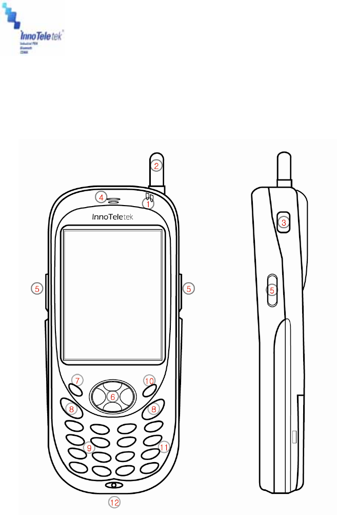
1. MC5000,OPTIMUS PDA SP5700 SERIES – General
view
Picture 1 Front and left side view
1. Indicator LED (Charging & Operation)
2. Antenna (for Wi-Fi & GSM)
3. USB Host connector
4. Speaker
5. Scan Trigger
6. 4 Way Navigation Pad
7. Power Button
8. Send & End Buttons for WWAN
9. Numeric Key Pad
10. Keypad Backlight Button

Revised Version/ March 2007
User Manual
Copyright © 2007
InnoTeletek, Inc. 11
11. Function Key
12. Universal I/O connector
2. Getting Started
2.1 Charging the Battery
Before using the PDA for the first time, recharge the Li-ion Battery. When charging is completed
indicating LED turns GREEN. It usually takes approximately 3 hours. Now, given this
information place your MC5000,OPTIMUS PDA SP5700 SERIES into the cradle and charge it.
Note: When you are going to charge the PDA for the first time, do not you remove the battery
before it is fully charged as it may cause malfunction. To ensure the quickest recharge
time, turn the PDA into a sleep mode.
To charge the battery:
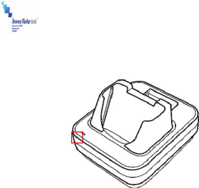
① Connect the cradle to the power supply source.
② Slide your PDA into the cradle until red LED lights up. To charge spare battery, insert the
battery into the slot at the top of the cradle. The charger starts operating automatically, and
completes charging in within 3 hours.
Picture 2 Positioning PDA in the cradle
Revised Version/ March 2007
User Manual
Copyright © 2007
InnoTeletek, Inc. 12
③ When LED turns RED it indicates that the battery is charging status. As the process is
completed, LED changes into GREEN.
Picture 3 Charging process
Note: MC5000,OPTIMUS PDA SP5700 SERIES is equipped with a memory backup battery.
The backup battery allows storing data in memory when the main battery is removed or
discharged. If the PDA remains without the main battery for more than 1 hour, the backup
battery discharges. It is highly recommended to replace the main battery within 10
minutes or keep charging the battery when the PDA is inserted in the cradle. Otherwise
your data may be lost.
CAUTION
RISK OF EXPLOSION IF BATTERY IS REPLACED BY AN INCORRECT TYPE.
DISPOSE OF USED BATTERIES ACCORDING TO THE NATIONAL CODE OR RECYCLING PROGRAM
2.2 Turning on/off
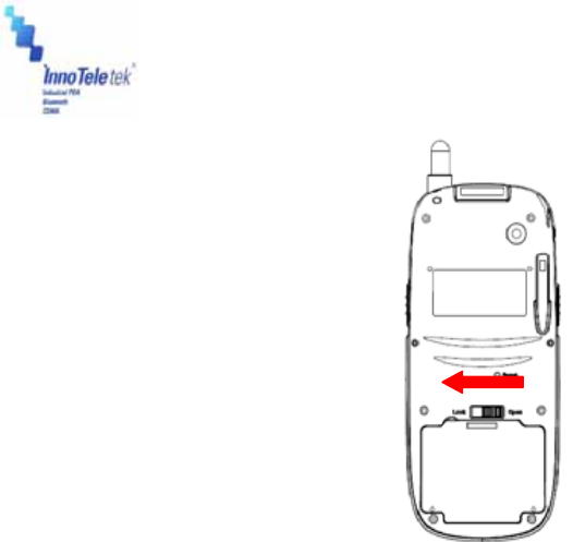
1) When you are replacing the batteries for the first time
① Pull out the rubber latch from the cover’s slot.
② Slide the cover left.
Revised Version/ March 2007
User Manual
Copyright © 2007
InnoTeletek, Inc. 13
Picture 4 Battery cover
② Insert the battery in the compartment in accordance with its correct positioning. Ensure
that the top of the battery adhere to the place first, and then you can fix its bottom. To close
the compartment, slide the cover on the right direction and lock the hook.
Revised Version/ March 2007
User Manual
Copyright © 2007
InnoTeletek, Inc. 14
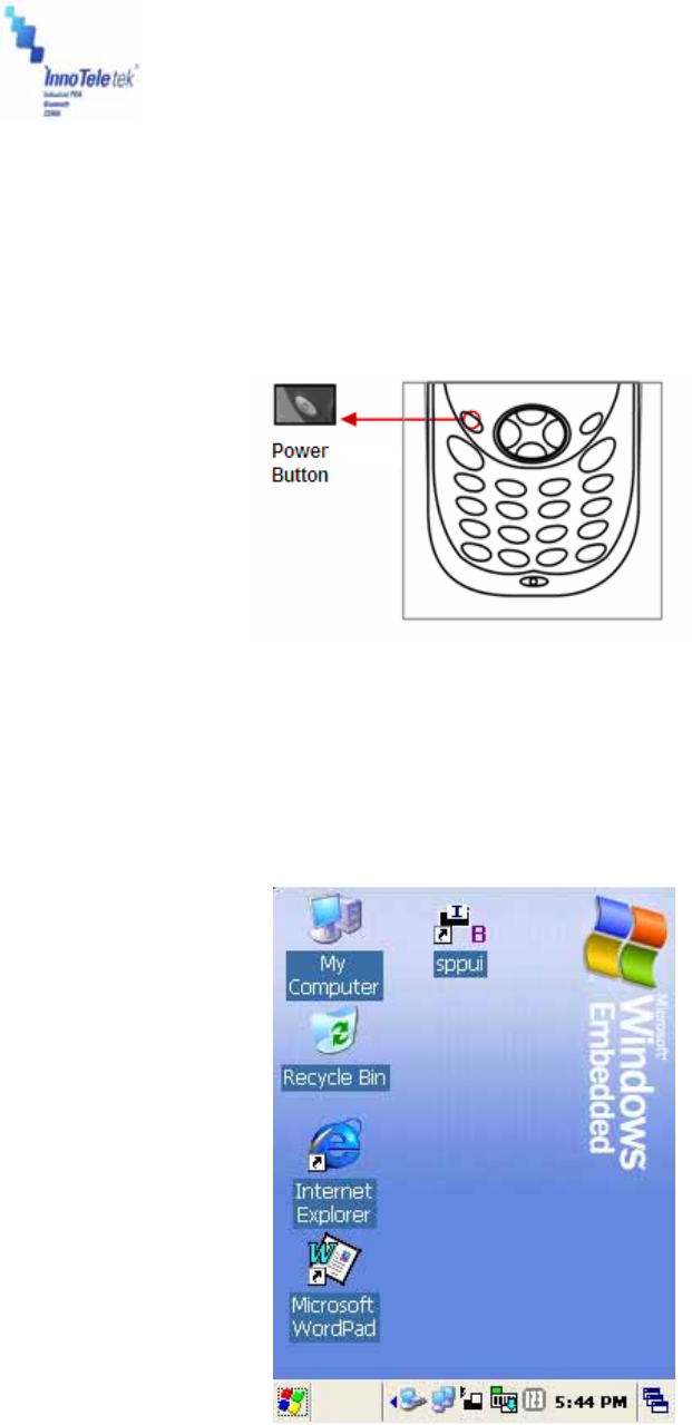
2) How to use the power button to turn on your MC5000,OPTIMUS PDA SP5700
SERIES
① Press the Power button to turn the PDA on.
- If you press and then hold the Power button for about 3 seconds, PDA switches into
sleep mode and turns off.
Picture 5 Power button
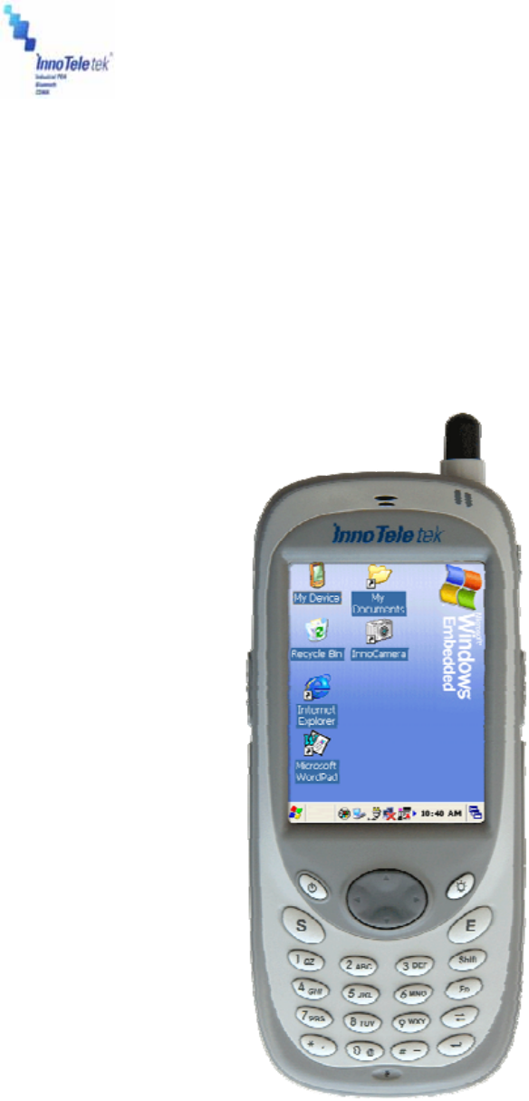
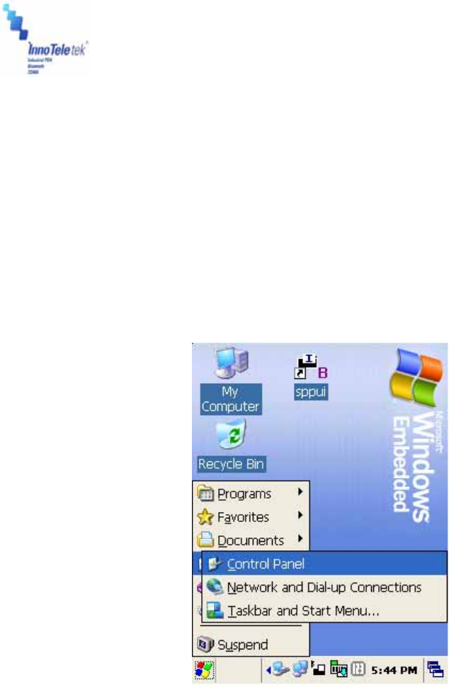
② When the booting process is finished, Windows® logo will be displayed on a desktop as
illustrated below.
Picture 6 Desktop background
③ If the Power button does not activate your PDA, you should execute a hard reset. For
Revised Version/ March 2007
User Manual
Copyright © 2007
InnoTeletek, Inc. 15
details refer to the section “Performing a Hard Reset.”
3) Turning off your MC5000,OPTIMUS PDA SP5700 SERIES
① Press and hold the Power button for 3 seconds or tap Suspend on the start menu.
- It is possible to set your terminal to auto-suspend status or to auto-turn off after specified
period of time what will allow you to save the battery’s power.
- Power setting method: Tap Start → Settings → Control Panel. Double tap the Power
button and select Schemes Tab.
Picture 7 Power setting from the control panel
② It is recommended to remove the battery from the PDA when it is not in use for a long
time.

Revised Version/ March 2007
User Manual
Copyright © 2007
InnoTeletek, Inc. 16
3. Settings
3.1 Sleep Mode
1) To reduce energy consumption, push the Power button for 3 seconds or tap Start →
Suspend, and your terminal will switch into a sleep mode. Data stored in RAM remains
unchanged when turning into sleep mode.
2) To wake up from sleep mode, press the Power button. When the system wakes up, the
screen will display the same view displayed before sleep mode.
3.2 LCD Display
1) To save battery power it is recommended to change the backlight settings.
Tap Start → Settings → Control Panel, then Double tap Display.
2) Press Backlight tab and select required option.
3.3 Volume & Sounds
To change sounds and the volume tap Start → Settings → Control Panel, then double
tap Volume & Sounds icon.
3.4 Date/Time
In order to adjust the date and time, select Start → Settings → Control Panel, then
double tap on the Date/Time icon.

Revised Version/ March 2007
User Manual
Copyright © 2007
InnoTeletek, Inc. 17
4. PDA Management
4.1 Using the Stylus
The stylus is useful for command selection and entering data. The stylus functions are similar a
mouse connected to PC.
1) Tap: Touch the screen once with the stylus to open an item and select options.
2) Drag: Hold the stylus on the icon and drag it across the screen to selected area. Drag in a
list to select multiple items.
Note: 1. If the surface of the display becomes dirty, clean it with a soft cloth before using the
stylus pen.
2. Take care not to scratch the screen. When working MC5000,OPTIMUS PDA SP5700
SERIES , use only the provided
stylus that is intended for use with the PDA touch-screen. Never use a pen, pencil
or other sharp pointers on the surface of the MC5000,OPTIMUS PDA SP5700 SERIES
screen.
3. Do not let children to play with the stylus. Contact with the end edge may cause injury.
Please keep the PDA away from children.
4.2 Calibrating the Screen
When you tap with the stylus and programs or functions are not activated correctly, you should
calibrate the screen. Calibration allows aligning the cursor on the touch-screen. The method is
as follows:
1) To calibrate your screen, select Start → Settings → Control Panel, next double tap the
Stylus icon, then indicate Calibration tab→ Recalibrate button.
2) Take the stylus from its holder on the back of the terminal.
3) Tap the center of the cross mark that appears on the screen with stylus.
Picture 8 Calibration screen Picture 9 Calibration settings completion
Revised Version/ March 2007
User Manual
Copyright © 2007
InnoTeletek, Inc. 18
4.3 Resetting
If the screen freezes or the terminal becomes inoperative, you may need to reset your PDA.
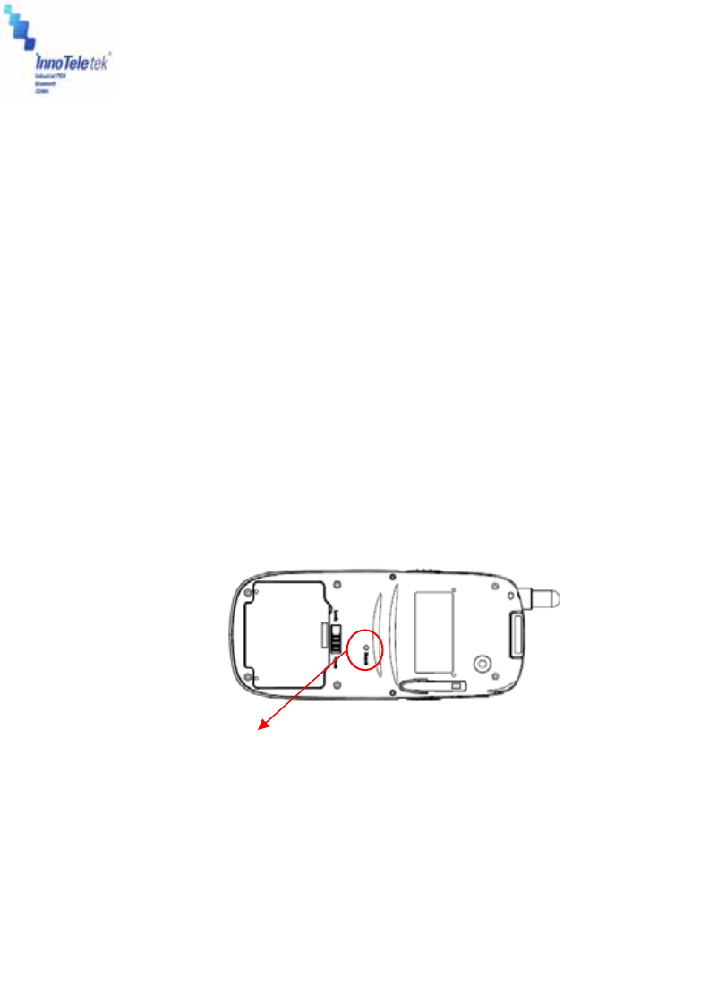
4.3.1 Performing a Soft Reset
Note: Transfer all stored data into a computer otherwise files that are open during a soft reset
may not be retrieved.
To perform a hard reset, press Reset Button located on the right side above the Battery Cover.
Picture 10 Reset buttons
Note: Soft reset restarts MC5000,OPTIMUS PDA SP5700 SERIES and saves all stored
records.
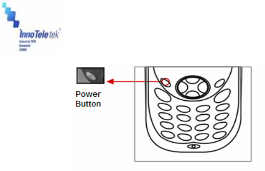
4.3.2 Performing a Hard Reset
By executing hard reset formats, preferences, date/time, and other settings are restored to their
factory default values.
To perform a soft reset, press reset button simultaneously the Power and Reset buttons.
Picture 11 Power & Reset button
Press the Reset Button here by using your stylus
Revised Version/ March 2007
User Manual
Copyright © 2007
InnoTeletek, Inc. 19
Note: Hard reset not only restarts your PDA, but also erases all stored records and entries in
RAM. Therefore, perform a hard reset only in cases when a soft reset mode does not
work.
! BE CAREFUL WHEN YOU PERFORM A HARD RESET SEVERAL TIMES
CONSECUTIVELY WITHIN SHORT PERIOD OF TIME, IT MAY CAUSE THE SCREEN TO
BECOME BLANK ACCOMANIED BY VERTICAL LINES DISPLAY ON IT.

Revised Version/ March 2007
User Manual
Copyright © 2007
InnoTeletek, Inc. 20
5. Applications
5.1 Creating documents
You can create a new document on your PDA with Microsoft WordPad®1, or work on an
existing one by sending it from the PC to your MC5000,OPTIMUS PDA SP5700 SERIES . Data,
files, and document uploads/downloads between PDA and computer are controlled by the
Microsoft ActiveSync® software.
There are two ways to enter characters into the document using document-editing programs:
- Using the keyboard
- Using the handwriting recognition program.
Detailed method for making documents with each of the above mentioned methods are as
follows:
Microsoft WordPad® is a registered trademark of Microsoft.
Revised Version/ March 2007
User Manual
Copyright © 2007
InnoTeletek, Inc. 21
1) Using the keyboard
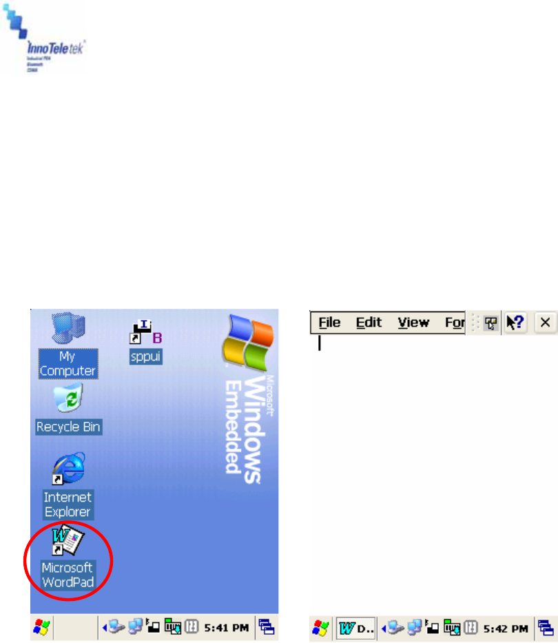
① Tapping on the WordPad icon from the Start menu or on the shortcut from the screen,
runs Microsoft WordPad®, the document-editing program.
The below illustrated pictures demonstrate how to use the screen shortcut for activating
WordPad. By double tapping on the Microsoft WordPad® icon (Picture 12), the display of
opened Microsoft WordPad® processor will appear (Picture 13).
Picture 12 WordPad shortcut Picture 13 New Document display
Revised Version/ March 2007
User Manual
Copyright © 2007
InnoTeletek, Inc. 22
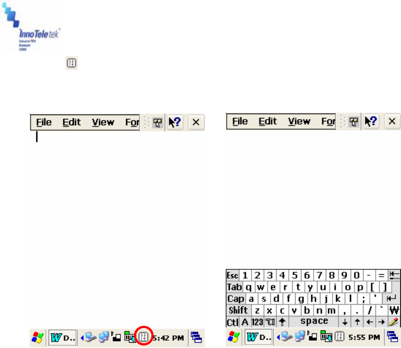
② Tap on at the bottom of the screen as it is shown on the Picture 14. Next the drop-
down menu will appear. Then select Keyboard (Picture 15).
Picture 14 Keyboard Icon Picture 15 Keyboard Panel
③ When the keyboard display appears on the lower part of the screen, tap the buttons with
characters to enter text into your document.
Note: You can also use the PDA’s keypad to input characters. The keypad is a numeric so
that also recognizes the numbers (0~9). The keypad is color-coded to indicate
particular actions that are taken when the Shift key is being pressed.
Revised Version/ March 2007
User Manual
Copyright © 2007
InnoTeletek, Inc. 23
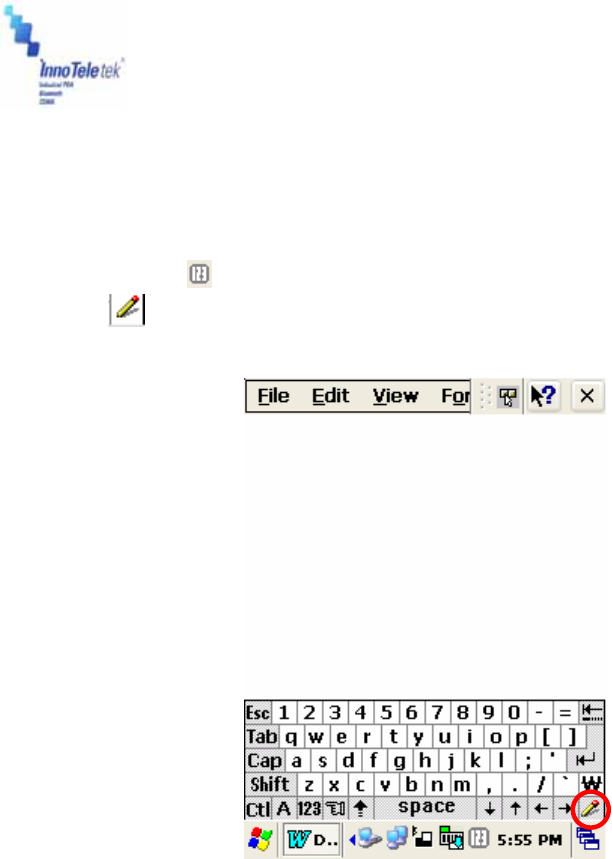
2) Using the character recognition program
① Open Microsoft WordPad®, the document-editing program.
② Tap on the icon located at the bottom of the screen. Then options will appear.
Select
Picture 16 Character recognition program selection
Revised Version/ March 2007
User Manual
Copyright © 2007
InnoTeletek, Inc. 24
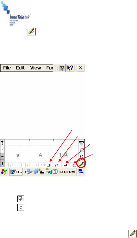
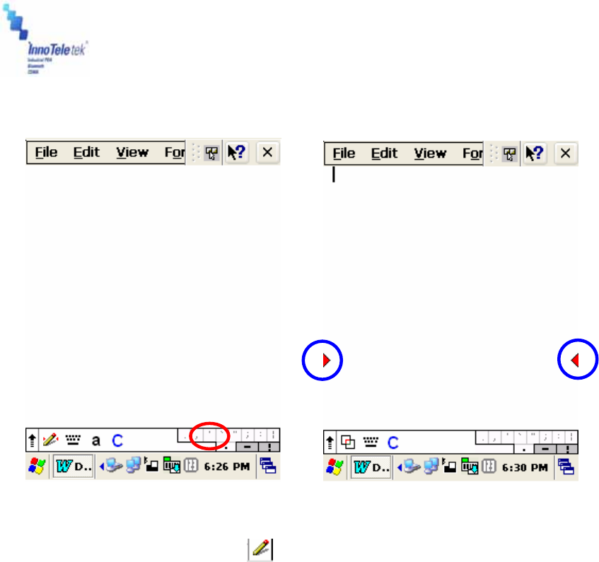
③ Press shaped button one more time. A window with the <a, A, 1·@> options
appears on the lower part of the screen. Upper case, lower case, and numbers/symbols
should be written in a certain fields marked by “a”, “A” and “1·@” – symbols that reflect three
different character recognition modes.
Picture 17 Screen boxes recognition
- Mode Conversion Input
- Ctrl: A shortcut key applied with “Ctrl + character” e.g. writing S in the Ctrl field calls
the save file dialogue box in the same way as in case of pressing simultaneously
Ctrl+S for the keyboard.
④ To display full screen mode for writing, tap on the - shaped button located on the
right side of the application (circled area on the Picture 17). Then, if you write letters using
your stylus, they will be converted into a text on the top of the screen.
Tab
Back Space
Space
Enter
Revised Version/ March 2007
User Manual
Copyright © 2007
InnoTeletek, Inc. 25
Picture 18 Full screen recognition mode Picture 19 Split screen mode
⑤ In order to split window, tap the - shaped button on the bottom menu bar at the full
screen mode. Now, upper part of the display located above the red arrows (circled in blue
on the picture below) is for capital letters input space and the lower part of the screen is
designated for small letters input.
Revised Version/ March 2007
User Manual
Copyright © 2007
InnoTeletek, Inc. 26
5.2 Barcode Scanning
5.2.1 Laser Scan Engine
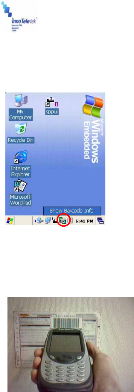
1) Open the barcode scanning program from the shortcut on the screen.
Picture 20 Barcode scan Test
2) Place the scanner in alignment to the direction of a barcode and press one of trigger
buttons. Let RED laser beam line cover the barcode.
! DO NOT KEEP THE SCAN BUTTON PRESSED TOO LONG; IT MAY RESULT IN SCAN
ENGINE FAILURE OR MALFUNCTIONING.
Picture 21 Barcode scanning
Revised Version/ March 2007
User Manual
Copyright © 2007
InnoTeletek, Inc. 27
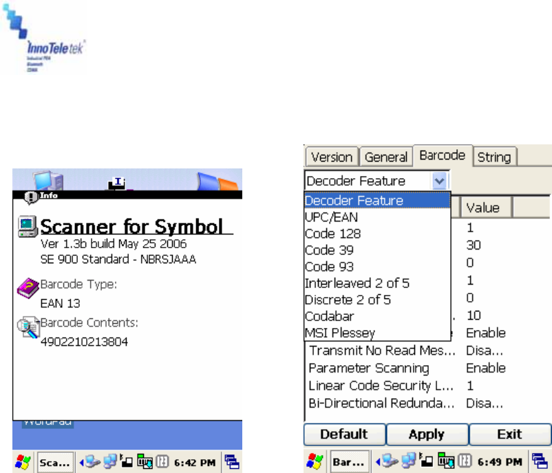
3) A short beep sound indicates successful accomplishment of decoding and the result will be
displayed in the scan window.
Picture 22 Scanning result Picture 23 Barcode selection list
4) In order to accelerate decoding process, you can disable imaging. Click Options button
from the menu bar and unmark the Enable Image command.
5) Readable codes
z Linear Symbologies: Codabar, Code 11, Code 128, Code 39, Code 93, EAN-8,
EAN-13, Interleaved 2 of 5, ISBT 128, MSI, Reduced Space Symbology, Straight 2 of
5 IATA, UPC-A, UPC-E, UPC-E1
Revised Version/ March 2007
User Manual
Copyright © 2007
InnoTeletek, Inc. 28
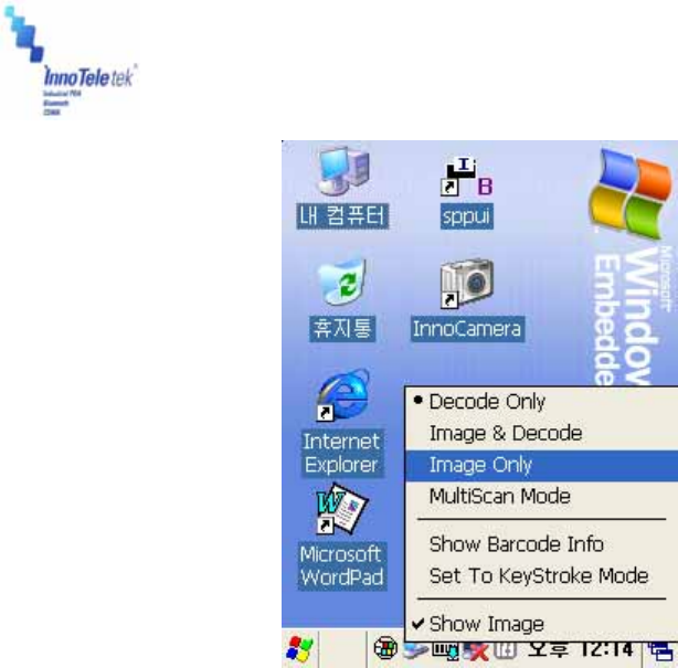
5.2.2 Image Scan Engine
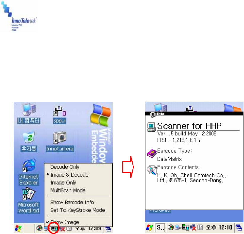
1) Run the barcode image scanning program by tapping a shortcut on the background screen.
Picture 24 Opening barcode image scan program
2) Place the PDA’s scanner in aligned with a barcode position and press one of trigger
buttons. Let Green laser beam line cover the barcode.
! DO NOT KEEP THE SCAN BUTTON PRESSED TOO LONG; IT MAY RESULT IN SCAN
FAILURE OR DEVICE MALFUNCTION.
3) A short beep will indicate successful decoding. And the result will be displayed appears in
the scan window.
4) In order to accelerate decoding process, disable imaging by using the Option menu. Using
stylus, tap on the Option tab from and then unmark the Enable Image on the drop down list.
Revised Version/ March 2007
User Manual
Copyright © 2007
InnoTeletek, Inc. 29
Picture 25 Disabling image function
5) Readable codes
z Linear Symbologies: Codabar, Code 11, Code 128, Code 39, Code 93, EAN-8,
EAN-13, Interleaved 2 of 5, ISBT 128, MSI, Reduced Space Symbology, Straight 2 of
5 IATA, UPC-A, UPC-E, UPC-E1
z Stacked Symbologies: Codablock F, Code 49, EAN·UCC Composite, Micro
PDF417, PDF 417, TCIF Linked Code 39 (TLC39)
z 2D Matrix Symbologies: Aztec Code, Aztec Mesa, Data Matrix, MaxiCode, QR
Code
z Postal Symbologies: Australian Post, British Post, Canadian Post, Japanese Post,
KIX (Netherlands) Post, Planet Code, Postnet,
z OCR Fonts: OCR US Money Font
Revised Version/ March 2007
User Manual
Copyright © 2007
InnoTeletek, Inc. 30
5.3 Connecting with a Desktop
ActiveSync® is the software that allows users to move files, update message contents, and
address book between desktop and MC5000,OPTIMUS PDA SP5700 SERIES . When the
PDA’s cradle and desktop computer are connected with USB cable, insertion of your
MC5000,OPTIMUS PDA SP5700 SERIES into the cradle activates a Microsoft ActiveSync
window, which appears on the desktop and indicates the synchronization status.
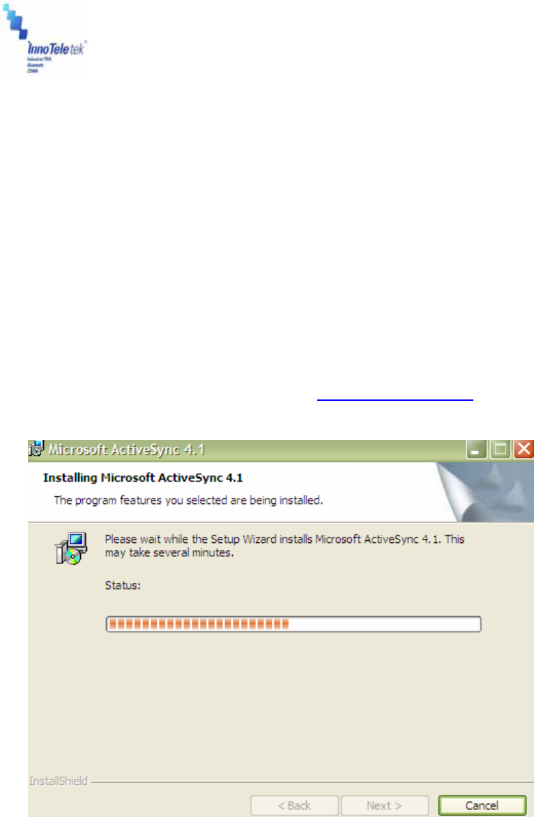
5.3.1 Installing ActiveSync® on a Desktop
① Insert the ActiveSync CD in the CD-ROM drive. The installation manager will lead you
quickly through the installation process. You can also download the latest version of the
software from Microsoft Corporation website at http://www.microsoft.com
Picture 26 ActiveSync 4.1 setup wizard
② If the auto installation screen does not appear, click on the setup.exe file on the
accompanied CD-ROM.
Revised Version/ March 2007
User Manual
Copyright © 2007
InnoTeletek, Inc. 31
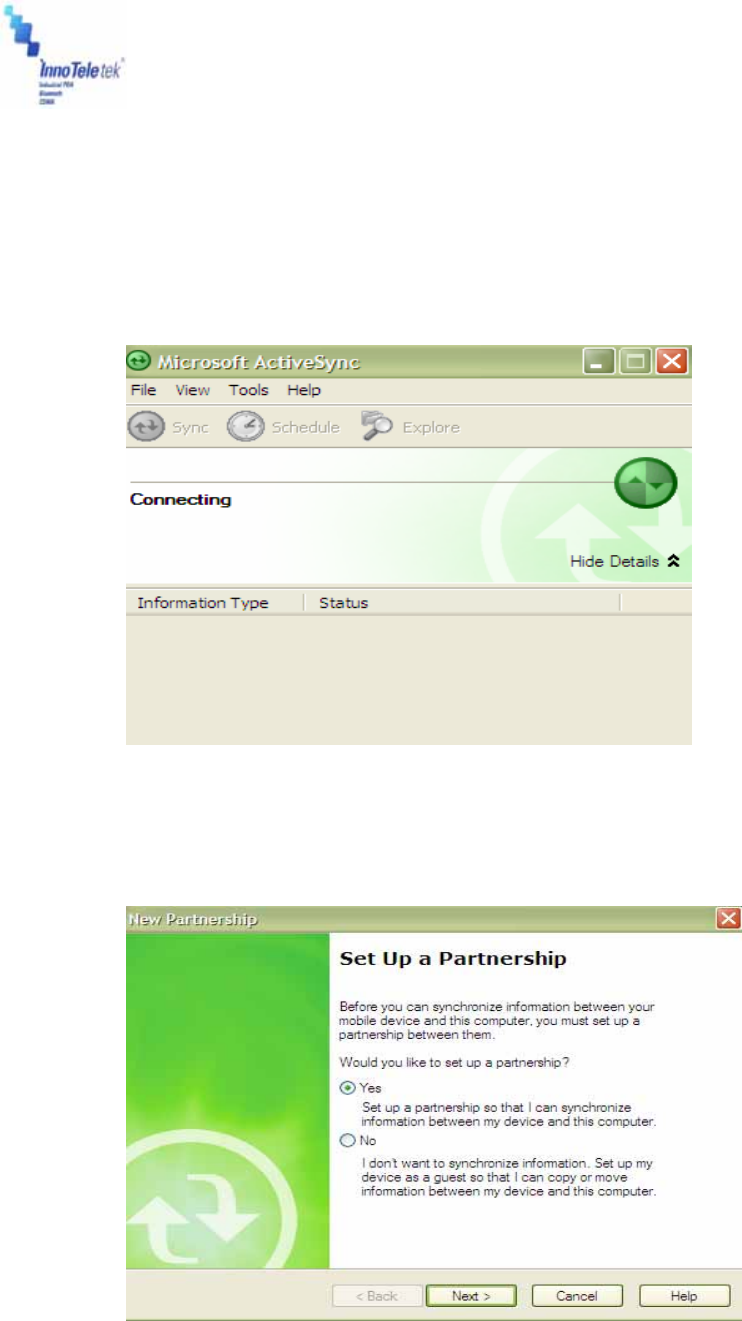
5.3.2 Setting up a partnership
① Insert your MC5000,OPTIMUS PDA SP5700 SERIES in the cradle, which is connected
to the desktop computer by a USB or RS232 cable. Then the screen will display a window
indicating that the PDA is being connected.
Picture 27 Connection process
② The desktop computer and your PDA will attempt to synchronize. As a result the
partnership window appears. Tap on Yes button and then select Next.
Picture 28 Partnership set up window
Revised Version/ March 2007
User Manual
Copyright © 2007
InnoTeletek, Inc. 32
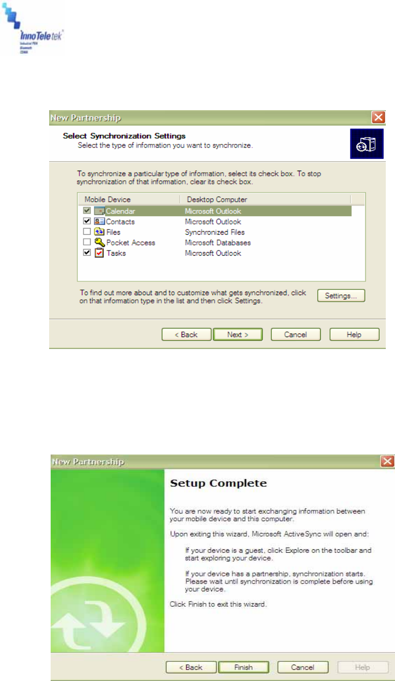
③ The Select Synchronization Settings Window appears. Here, select the items you
want to synchronize, and then press the Next button.
Picture 29 Synchronization options
④ To complete the process select the Finish button. Then the basic settings and
configuration for a PC and the PDA connection will be established.
Picture 30 Setup completion
Revised Version/ March 2007
User Manual
Copyright © 2007
InnoTeletek, Inc. 33
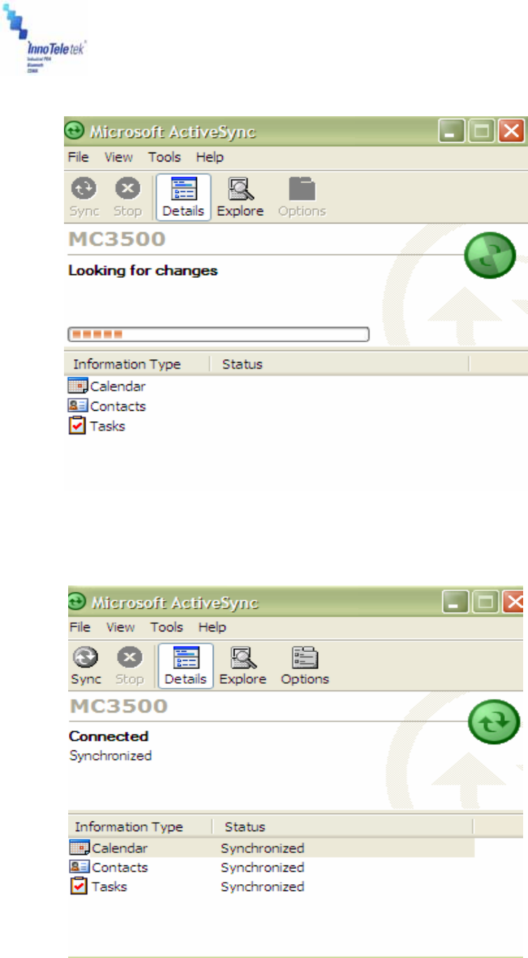
⑤ Go through the earlier steps to run ActiveSync®.
Picture 31 Synchronization process
⑥ At the end, the window informs that synchronization has been successfully completed.
Revised Version/ March 2007
User Manual
Copyright © 2007
InnoTeletek, Inc. 34
Picture 32 Synchronization status
5.4 Wireless LAN
With a wireless LAN type model, you can log into the Internet wirelessly through the internal
WLAN card. However, your PDA must be set up in accordance with the equipment specification
(including Hotspot) that is required to access the wireless LAN. To meet these needs
MC5000,OPTIMUS PDA SP5700 SERIES must be properly configured.
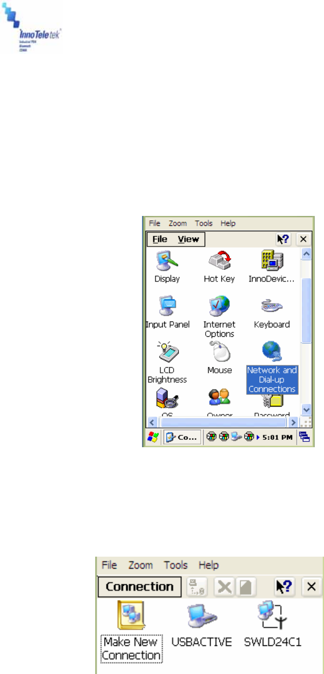
① Select Start → Settings → Control Panel, and then double tap Network and Dial-up
Connections icon.
Picture 33 Network and Dial-up Connections icon
② Select an appropriate driver to add the Wireless LAN card.
Picture 34 Initializing connection process
Revised Version/ March 2007
User Manual
Copyright © 2007
InnoTeletek, Inc. 35
Note: Driver types may vary depending on applied wireless LAN card. Therefore, you should
check your driver characteristics before attempting to activate connection.
③ Dynamic IP
Select Obtain an IP address via DHCP server. In this case the wireless communication is not
available because DHCP server does not assign static IP addresses.
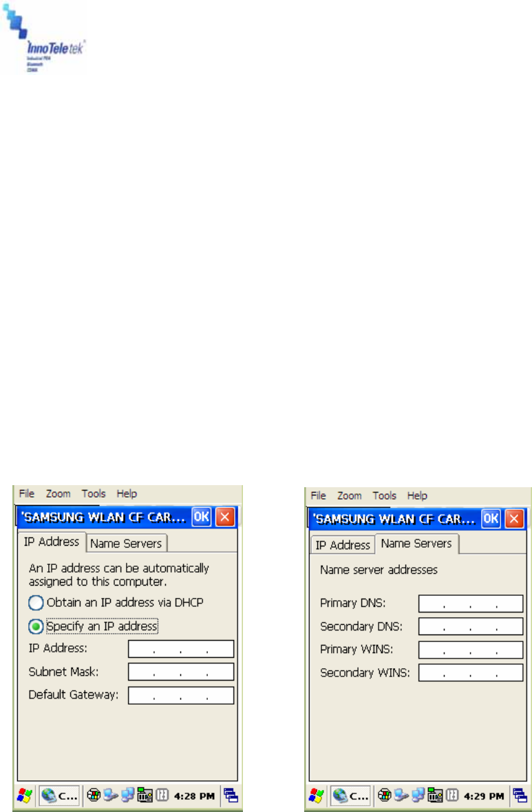
④ Static IP
i) Select Start → Settings → Control Panel, then double tap Network and Dial-up
Connections.
ii) Select relevant driver to add Wireless LAN card. For example, this unit is equipped with
CISCO product.
iii) Select the IP Address tab, and then point one the Specify an IP address radio button.
Enter the IP Address, Subnet Mask and Default Gateway data.
iv) Press the Name Servers tab, and enter required data. Consult the network manager for
providing necessary data.
Picture 35 IP address and server address assignation
Revised Version/ March 2007
User Manual
Copyright © 2007
InnoTeletek, Inc. 36
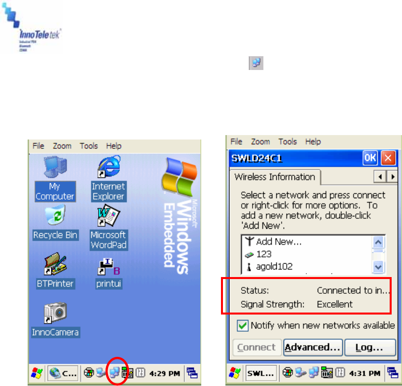
* To check your network connection status, select the icon on the Taskbar, and then
click on the Wireless Information tab. The Signal Strength is indicated as Very Good or
Good etc…
Picture 36 Network connection icon Picture 37 Connection status
v) Select the IP Information tab, and make sure that the static IP address data has been
entered correctly.
Note: The IP address data is not lost when a soft reset is performed. However, it should be re-
entered again, if a hard reset has been executed.
Revised Version/ March 2007
User Manual
Copyright © 2007
InnoTeletek, Inc. 37
5.5 GSM / GPRS
In general GPRS module works as a mobile data service to users of GSM mobile devices of
2.5G and provides moderate speed data transfer, by using TDMA channels in GSM network. In
order to set up a GPRS connection, a user needs to specify Access Point Name (APN), user
name and password, and very often IP address, all provided by the network operator.
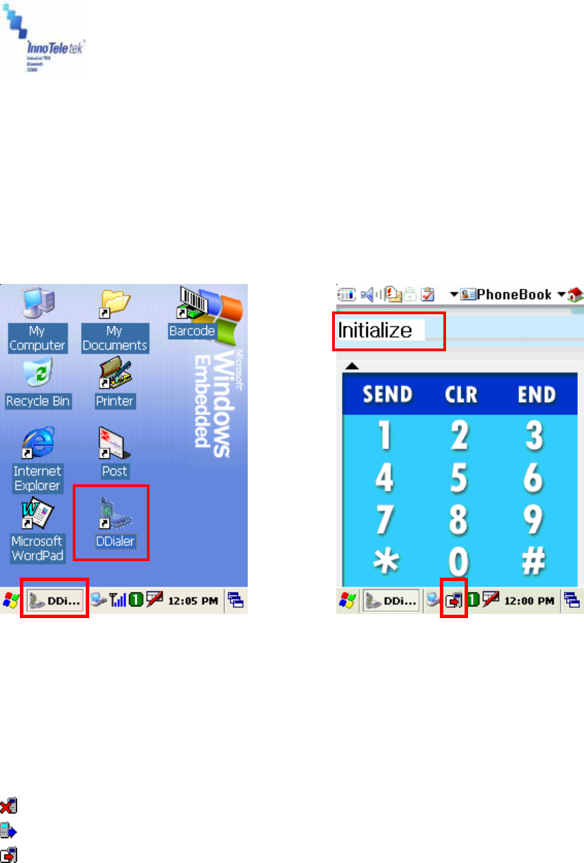
5.5.1 Initializing the Modem
Picture 38 Running DDialer from the desktop Picture 39 Open DDialer display
① When PDA startup, the DDialer is activated automatically and initializes GSM Module
When initialization is under process you can observe the following icons in the Taskbar:
: Modem suspended
: Modem activation in progress
: SIM card information is being loaded
Revised Version/ March 2007
User Manual
Copyright © 2007
InnoTeletek, Inc. 38
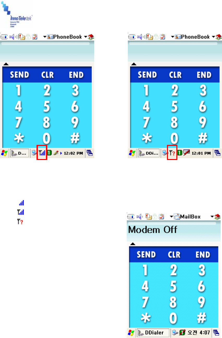
Picture 40 Signal strength Picture 41 Connection quality
② Antenna and signal icon indicates GSM or DCS signal strength as follows:
: Found signals only
: Found signals and identified an operator
: Service area not available
Picture 42 Operating mode
You can switch on/off GSM module by pressing “END” button on the screen for a while.
After turning GSM function off, you will notice a display of “Modem Off” message.
Revised Version/ March 2007
User Manual
Copyright © 2007
InnoTeletek, Inc. 39
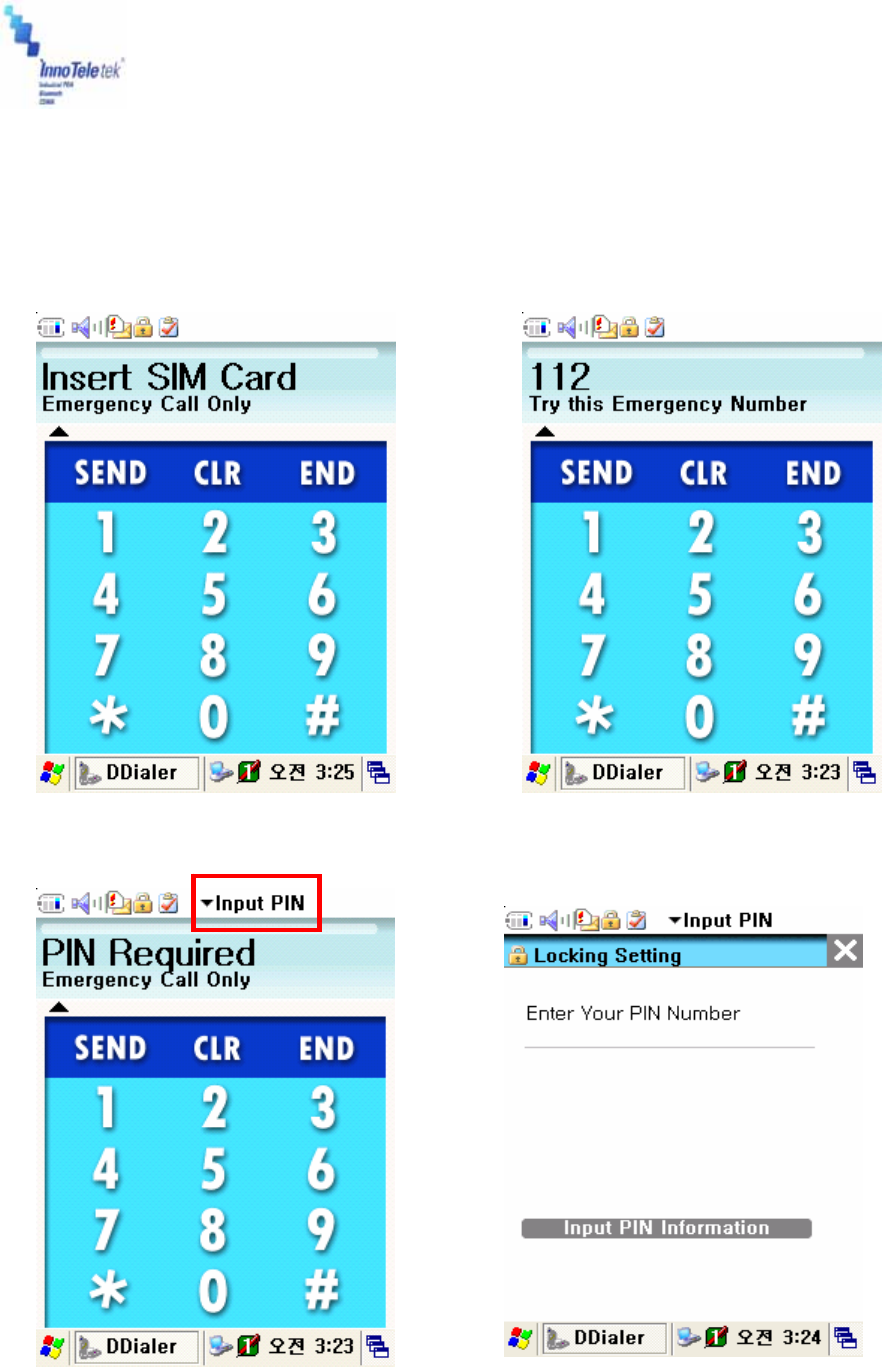
5.5.2 Checking Subscriber Identity Module (SIM)
As soon as the Phone User Interface starts, the program checks stored SIM data. The SIM card
requires PIN information and to enter it you should precede in accordance with the method
depicted on the Pictures 45 and 46.
Picture 43 Request for SIM card insertion Picture 44 Availability of emergency calls
Picture 45 Request for PIN Picture 46 Entering PIN data
Revised Version/ March 2007
User Manual
Copyright © 2007
InnoTeletek, Inc. 40
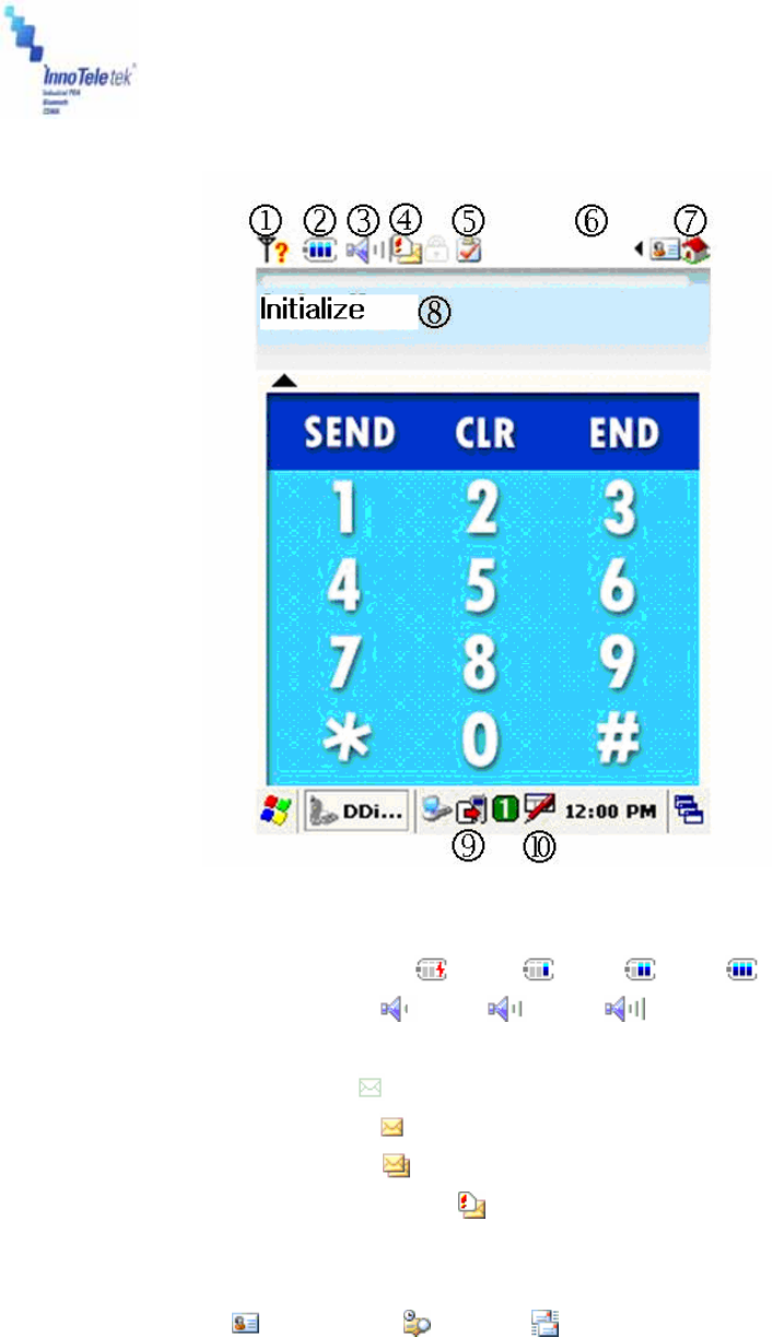
5.5.3 Menu
Picture 47 Display after connecting to a network
① Battery information ( Empty : Low : Mid : Full : )
② Ear volume status ( Min : , Mid : , Max : )
③ SMS memory status
No unread messages :
Single unread message :
Many unread messages :
SIM card is full (or in test mode ):
④ UI lock indicator
⑤ Mode status
⑥ UI Menu : Phonebook / History / Message selection
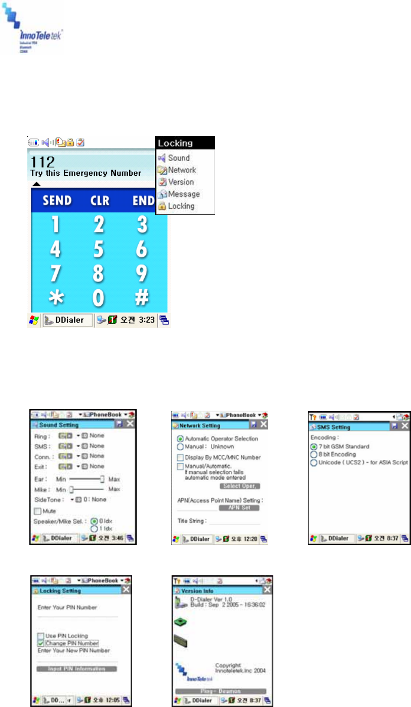
⑦ Phone setting menu : Sound, Network, Version, Message, Locking (PIN), Menu
Setting
⑧ Display window status
⑨ Modem status / Signal strength
⑩ Keyboard icon
Revised Version/ March 2007
User Manual
Copyright © 2007
InnoTeletek, Inc. 41
1) Phone Setting Menu
Picture 48 Phone setup options
2) Setup options
By tapping items from Phone Setting Menu, you can open sound, network, SMS, lock, and
version info setup windows.
Picture 49 Sound setup Picture 50 Network setup Picture 51 SMS setup
Revised Version/ March 2007
User Manual
Copyright © 2007
InnoTeletek, Inc. 42
Picture 52 PIN edit Picture 53 Version info
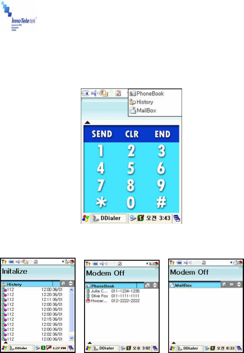
3) User Interface Menu
To change phonebook, check out history, and mailbox settings, tap on selected item on UI
menu drop-down list.
Picture 54 User Interface functions
Picture 55 History record Picture 56 Phonebook Picture 57 Mailbox
A) Call Log: Views call log and history
B) Phone Book: Displays list of callers and along with their names and respective
phone numbers
Revised Version/ March 2007
User Manual
Copyright © 2007
InnoTeletek, Inc. 43
C) Mail Box: Checks SMS box
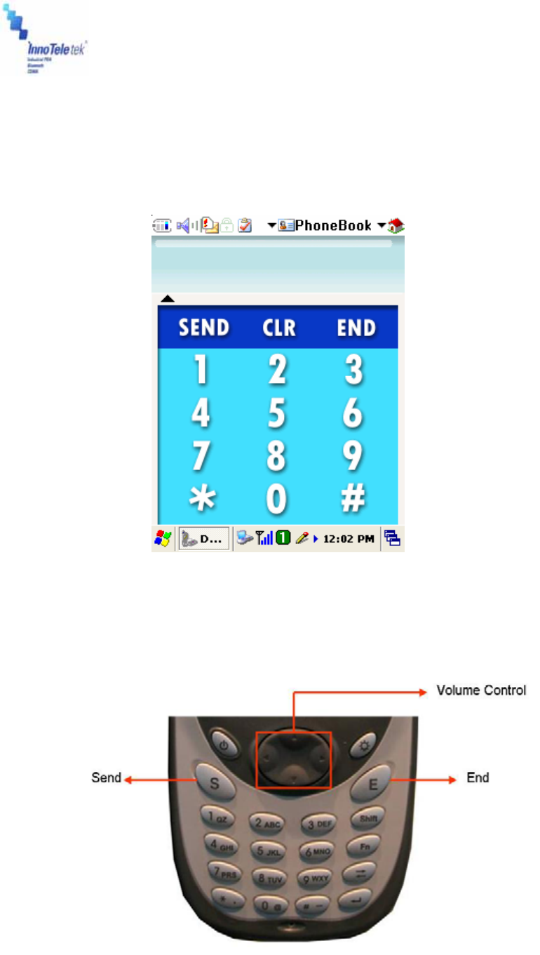
5.5.4 Voice call
4.1 Voice Dialing/Getting
If you want to make a call you should use the key pad or LCD touch-screen driven panel.
Picture 58 Touch-screen keypad
4) Voice call : Use the keypad (Send/End, number keys) or touch-screen LCD
5) Volume control : Navigate through the 4-way direction key pad (Up/Down)
Picture 59 Keyboard
Revised Version/ March 2007
User Manual
Copyright © 2007
InnoTeletek, Inc. 44
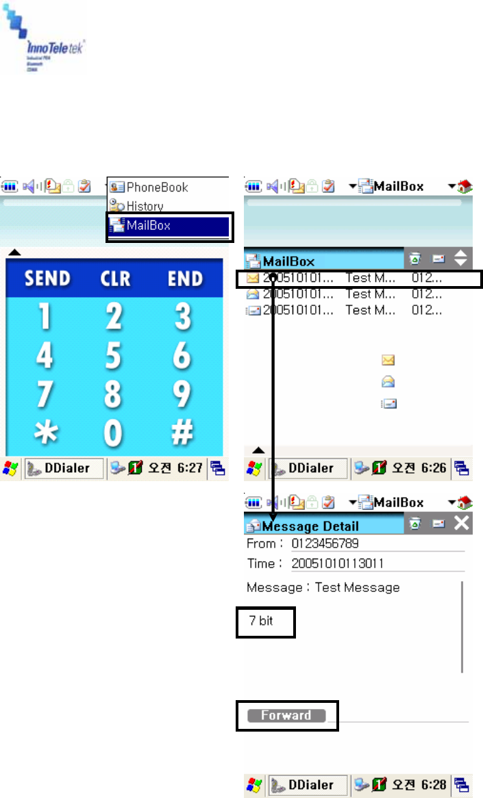
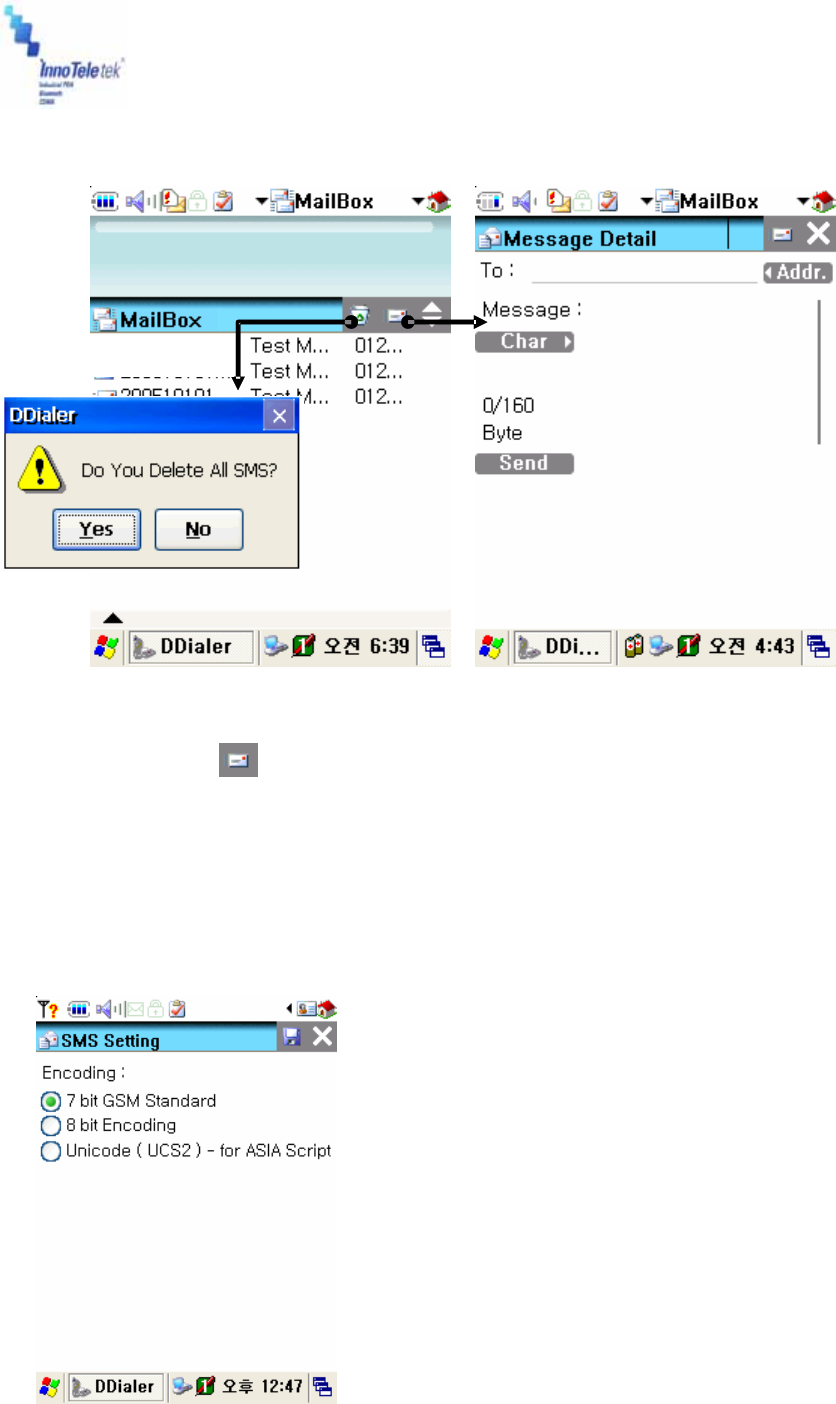
5.5.5 Short Message Service
Reading Stored SMS texts
Picture 60 Mailbox display
Stored
Message List
Encoding types
7 bit / 8 bit / UCS2
Phone number field
Message forwarding button
Unread message
Read message
Sent message
Revised Version/ March 2007
User Manual
Copyright © 2007
InnoTeletek, Inc. 45
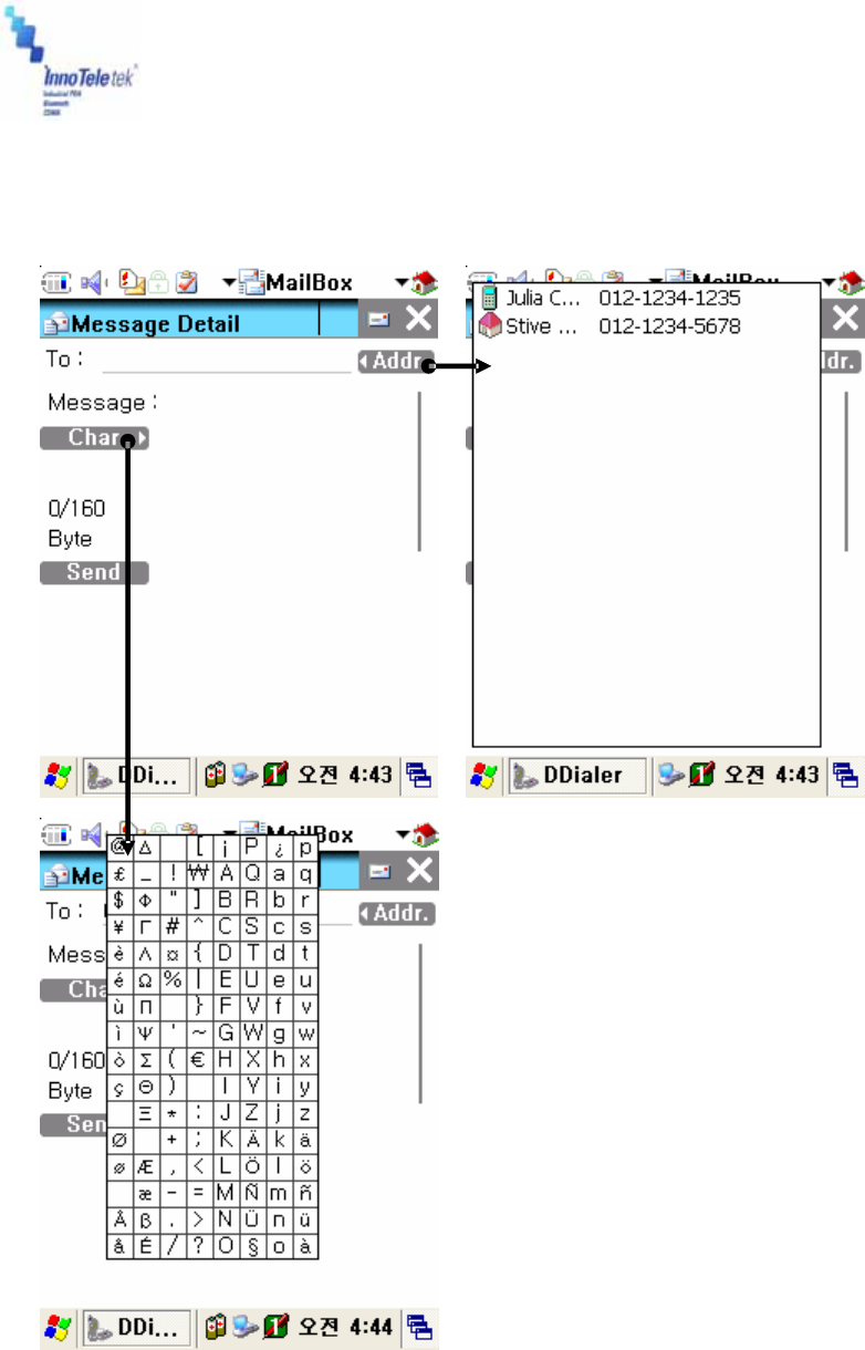
Sending a Message
Picture 61 Mailbox and SMS windows
⑪ Tap on the icon to write a message
⑫ In the Blue Box, write a message by using Character recognition program or
PDA’s keypad
⑬ Press Send Message button to initiate transmission process
⑭ Select an appropriate encoding program. Among SMS encoding options are: 7bit
standard, 8bit standard, and UCS2 (Unicode16).
Delete message icon
Revised Version/ March 2007
User Manual
Copyright © 2007
InnoTeletek, Inc. 46
Picture 62 SMS encoding program selection
Picture 63 Editing text and addressing SMS
The ‘Char’ button displa
y
s GSM
7bit Character and symbol list
The button displa
y
s address
book’s contents
After writin
g
a messa
g
e,
send SMS text b
y
pressin
g
the ‘Send’ button
Revised Version/ March 2007
User Manual
Copyright © 2007
InnoTeletek, Inc. 47
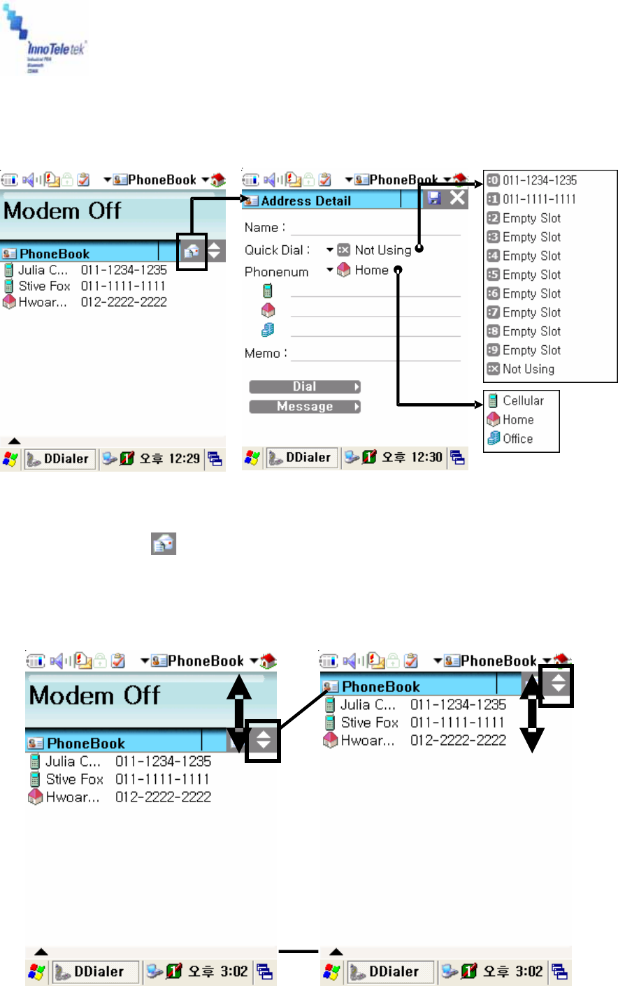
5.5.6 Phonebook
How to Add a New Phone Number
Picture 64 Adding a new contact
⑮ Tap on the icon to add a new address
16 Enter phone number and other information into the “Address Detail” window
17 Specify a “Quick Dial” number, or select primary phone number among cellular,
home and office phones
Slide for Up/Down
viewing the whole list
Picture 65 Phonebook content
Revised Version/ March 2007
User Manual
Copyright © 2007
InnoTeletek, Inc. 48
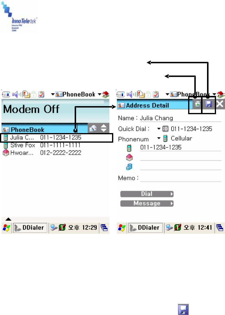
Updating Phone Numbers
Picture 66 Management of phonebook numbers
① Edit PhoneBook
② Select phone number
③ When the “Address Detail” screen appears, update phone number information,
delete selected item, or save changes by tapping the icon
Dial to:
Send SMS to:
Update Changes
Delete Phone Number
Revised Version/ March 2007
User Manual
Copyright © 2007
InnoTeletek, Inc. 49
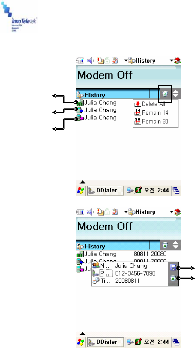
5.5.7 History
Picture 67 Tracking history records
Missed call
Sent call
Received call
Save to the PhoneBook
Delete indicated items
This button deletes
history record
Revised Version/ March 2007
User Manual
Copyright © 2007
InnoTeletek, Inc. 50
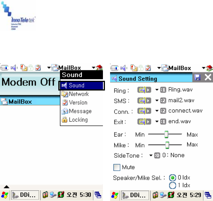
5.5.8 Sound Settings
Picture 68 Sound configurations
Thanks to this screen configuration tools you can change Ring Sound / Message Notification
Sound / Connect HO Sound and Network Register Sound / Hang-Up and Network Unregister
Sound, and other volume parameters.
Revised Version/ March 2007
User Manual
Copyright © 2007
InnoTeletek, Inc. 51
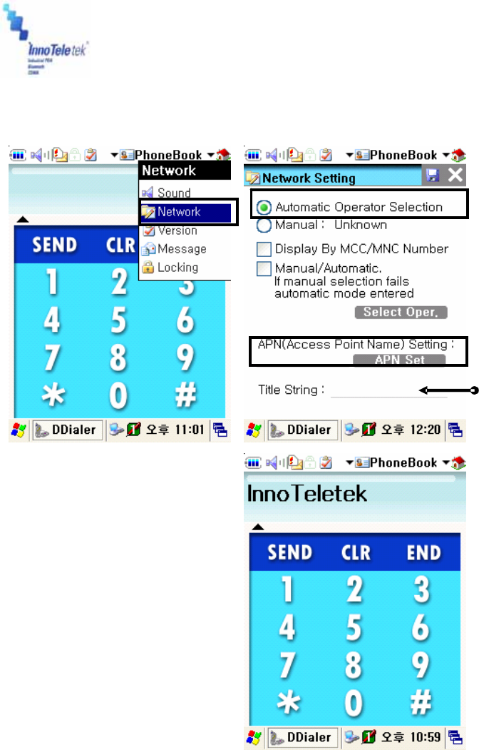
5.5.9 Setting a Wireless Network
Picture 69 Network advanced settings
When filling in this
field, you will set a
name for PhoneUI
front screen.
In this example, we
use for “InnoTeletek”
PhoneUI
Access Point Name for GPRS
Select Network Menu
Operator (PLMN)
Automatic Selection,
is set up as default
Revised Version/ March 2007
User Manual
Copyright © 2007
InnoTeletek, Inc. 52
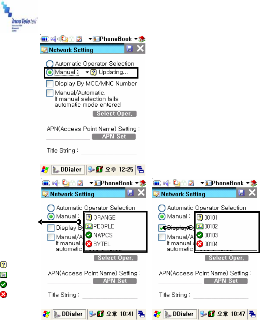
Picture 70 Connecting to network in manual mode
By selecting manual Operator
mode, the system will be searching
operators
Connected
Unknown
Available
Forbidden
Highlighted
icon indicates
status of the
operators
While pointin
g
at Displa
y
b
y
MCC/MNC Number’,
y
ou will
see the MCC/MNC value.
Revised Version/ March 2007
User Manual
Copyright © 2007
InnoTeletek, Inc. 53
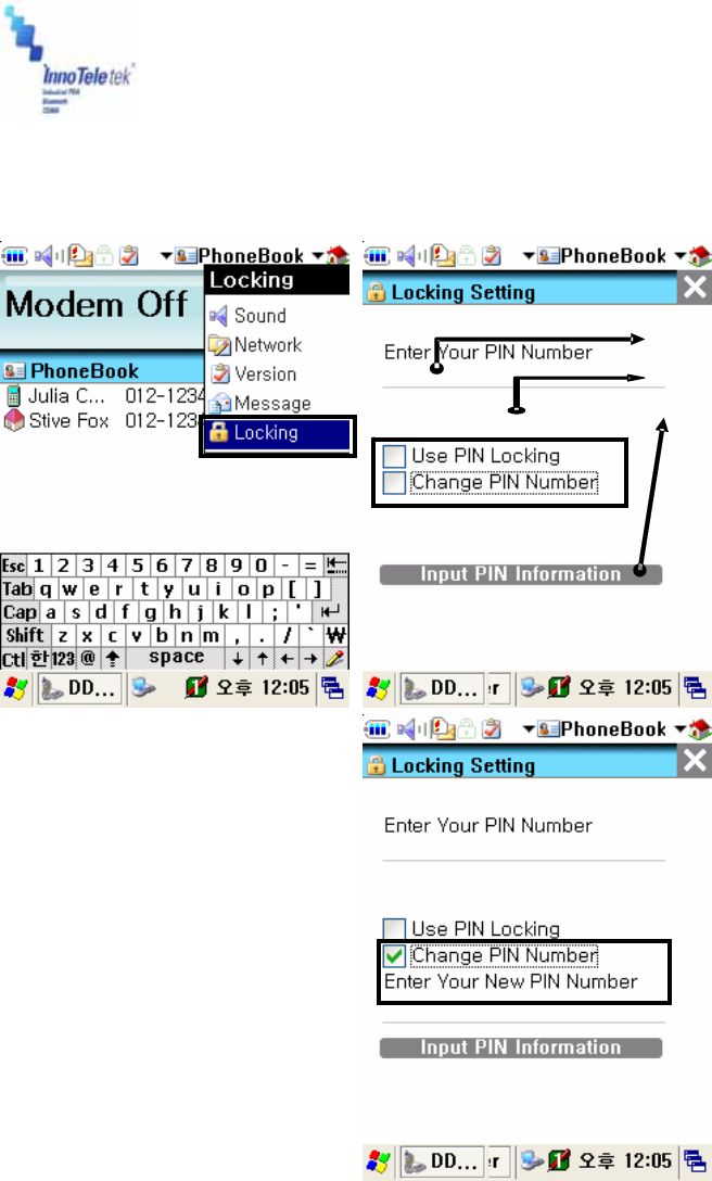
5.5.10 How to Lock the Menu
Picture 71 Locking menu values
1. Input your PIN number
2. Select PIN option (check box)
3. Press tab ‘Input PIN information’
If you selected ‘Change
PIN Number option Select
PIN option (check box)
Revised Version/ March 2007
User Manual
Copyright © 2007
InnoTeletek, Inc. 54
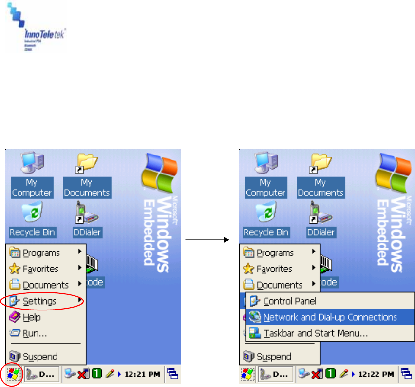
5.5.11 Connecting to GPRS Network
To establish a new GPRS network, you should set the Access Point Name (APN) first. After
having it done press APN press APN Set and Save icon.
Picture 72 Settings tab on the Start Menu Picture 73 Network Connections tab
Revised Version/ March 2007
User Manual
Copyright © 2007
InnoTeletek, Inc. 55
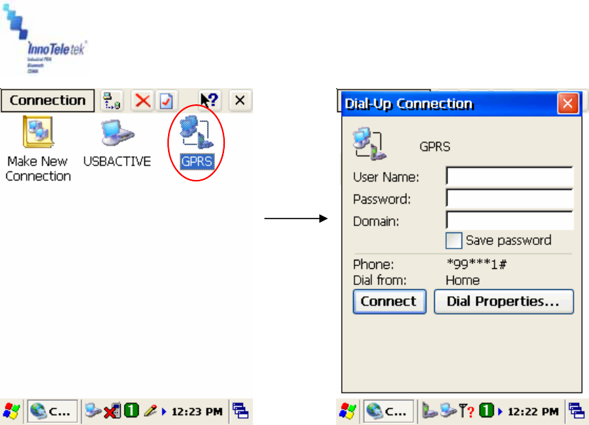
Picture 74 GPRS icon Picture 75 Dial-up connection window
Then run the GPRS connecting program according to the following method:
Tap Start → Settings → Network and Dial-up Connections. Double tap the GPRS button and
press Connect tab.

Revised Version/ March 2007
User Manual
Copyright © 2007
InnoTeletek, Inc. 56
6. Troubleshooting
Problem Cause Solution
Low-Battery Charge or replace the battery.
Problem with Reset
button’s rubber If reset rubber can be pressed with your finger,
then cut the tip of the rubber.
OS is not
loading Battery malfunction Take out the battery from the compartment, and
press the reset button. Then insert back the
battery into the PDA.
PDA turns itself
off
OPTIMUS_PDA is
inactive (Sleep Mode)
Press the Power button, then the windows
restores. Your PDA becomes idle after some
time of inactivity. User Idle switch state can be
set on the Power Properties window. Tap Start
→ Settings → Control Panel → Power.
Battery failure Replace battery. If your terminal still does not
operate, try a hard reset.
Device was removed
from cradle while battery
was charging
Insert your PDA into the cradle and start
charging. Assure that your terminal is turned off,
or in a sleep mode while being charged.
Battery does
not charge
I/O connector is not
clean Clean up the I/O connector.
PDA is not powered on Press the Power button.
Characters on
display are
invisible Battery is not charged Charge the battery.
IP error Fix the static IP address.
Communication
failure with
IrDA printer IP crash Check whether more than two users work under
the same static IP address.
The stylus pen
does not tap
correctly
Shortcut icons does not
activate the
corresponding function
Select Start → Settings and double tap on
Stylus. Then recalibrate the stylus.
Too many files stored in
memory module Delete unused files or transfer data to your PC.
Memory setting problem
Adjust the memory allocation. Tap Start →
Settings → Control Panel, then double tap the
System tab. Select Memory and adjust the
slider.
A message
appears stating
that your PDAs
memory is fully
occupied
Too many applications
are installed on your
Optimus_PDA
If you have installed new applications on your
PDA, remove unused applications to extend
memory capacity. Tap `4
Start → Settings → Control Panel, and
double tap on Remove Programs. Then select
useless programs and tap on Remove button.

Revised Version/ March 2007
User Manual
Copyright © 2007
InnoTeletek, Inc. 57
Table 1 Solving problems
Problem Cause Solution
Scan window is dirty Clean scanner window with a soft, wet cloth.
Object moves while
scanning Fix the object while scanning.
Scanning application is
improperly opened
Tap on Start, then Settings → Control Panel,
and select the System tab to verify whether the
unit is loaded with a scanning application or not.
Unreadable barcode Scan engine can not read damaged barcodes.
Distance between your
terminal and the object is
both; too far or too close
Adjust the distance between them at
approximately 6 inches, and try again.
PDA is not programmed
for the barcode Check whether your PDA is programmed to read
the type of barcode you are scanning.
Your PDA
does not
accept scan
data input
Scanning beam not
aligned with a barcode Angle the barcode at 45 degrees or place scan
beam against a barcode to use direct rays.
OPTIMUS_PDA was
removed from cradle
during communication
process
Insert you PDA into the cradle again.
Incorrect cable con-
figuration
Verify cable genuineness, and check the status of
connection.
ActiveSync is incorrectly
installed or configured Install the ActiveSync program again.
ActiveSync
does not
operate
Connected as a Guest,
not by previously created
name
Take the terminal out, then insert it the cradle
again and enter your name again.
Volume level is very low
or turned off
Check the volume slider in Volume & Sounds
(Tap on Start → Settings → Control Panel) to
ensure the volume is at adequate level.
Sound is not
audible Dust fills the speaker Clean up the speaker.
Characters are written
incorrectly To recognize handwriting input, characters must
be written carefully, in a certain way.
Program
does not
recognize
handwriting Character strokes are
written on the wrong part
of the LCD Fix the letter recognizer.
Revised Version/ March 2007
User Manual
Copyright © 2007
InnoTeletek, Inc. 58
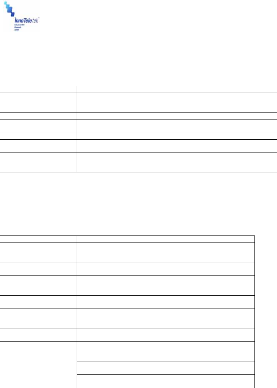
7. Specifications
7.1 Physical Characteristics
Dimensions* 78 W × 177 L × 34 H (Top); 26 H (Bottom) mm / 3.1 x 7.0 x 1.3 x 1.0 in.
Weight * 256g / 9.03oz. (WLAN, WPAN, Camera, Scanner Included/ Except Battery)
Drop Specification 1.5m / 5 ft onto Concrete Surface (Double Drop for Every Side)
Operating Temperature -20 ° to 50 °C (-4 ° to 122 °F)
Storage Temperature -30 ° to 70 °C (-22 ° to 158 °F)
Environmental Sealing IP54 (Dust and Water Splash Protected)
Humidity 5% to 95% RH Non-condensing
Electrostatic Discharge
(ESD)
8KVDC/Air, 4KVDC/Contact
Key Pad 2 Triggers, Power, Backlight (LED Backlight Supported), Start, End, 4 Way
Navigation Pad, Shift, Function, Backspace, Enter, 12 User-selectable
Keys (Numeric, English/ Korean)
Table 2 Physical specifications
* Subject to change without prior notice.
7.2 Performance
CPU Intel XScale PXA270 microprocessor (520MHz)
Operating System Microsoft Windows CETM5.0
Memory (ROM/RAM) - Flash ROM: 128 MB
- SDRAM: 128 MB
Display - 3.5" TFT Color LCD (Transflective Type)
- Resolution: 240 x 320 pixels
Standard Communications RS232, USB v1.1(Host, Client), IrDA v1.2
Sound (MIC and Speaker) Water-proof, Internal Microphone and Speaker for Voice Recorder
Expansion Slot Mini SD card slot
Radio Capacity - WWAN: CDMA(EVDO)(Optional), GSM/GPRS (Optional)
- WLAN: IEEE802.11b/g (Up to 11Mbps/54Mbps) (Optional)
Barcode Scanner 1D Barcode: UPC/EAN/KAN, Code 39/ 93/ 128, Interleaved 2 of 5,
etc.
2D Barcode: PDF417, QR Code, Data Matrix, Maxi Code, etc.
SW
- Desktop device manager: Microsoft® ActiveSync
Application Development - Microsoft Windows CE SDK, InnoTeletek SDK
Main Battery Rechargeable Li-Ion Battery
(3.7VDC, 2000mAh)
Back-up
Battery
Rechargeable Battery
(3.7V, 130mAh)
Battery Life 3 - 72 hours
Battery
Charge Time Less then 3 Hours
Table 3 Hardware specifications

Revised Version/ March 2007
User Manual
Copyright © 2007
InnoTeletek, Inc. 59
8. Limited Warranty Statement
General
This Limited Warranty applies to the InnoTeletek
brand name products sold with this Limited
Warranty Statement.
This Limited Warranty may be enforced in any
country where InnoTeletek or its authorized
service providers offer warranty service subject to
the terms and conditions set forth in this Limited
Warranty Statement.
However, warranty service availability and
response times may vary from country to country
and may also be subject to registration
requirements in the country of purchase.
InnoTeletek warrants that the InnoTeletek product
you have purchased from InnoTeletek or from an
InnoTeletek authorized reseller is free from defects
in materials and or workmanship under normal
use during the warranty period.
The warranty period starts on the date of purchase
from InnoTeletek or from a InnoTeletek authorized
reseller. You dated sales or delivery receipt,
showing the date of purchase of the product, is
our proof of purchase date.
During the warranty period, InnoTeletek will repair
or replace the defective parts with new parts, or, at
InnoTeletek’s discretion, used parts that meet or
exceed performance specifications for new parts.
All parts or products removed under this warranty
become property of InnoTeletek. The replacement
part or product takes on the warranty status of the
removed part or product, In the unlikely event that
your InnoTeletek product has a recurring failure,
InnoTeletek, at its discretion, may elect to replace
your product with comparable product. This is your
exclusive remedy for defective products.
Before returning any unit for service, be sure to
back up data and remove any confidential,
proprietary, or personal information. InnoTeletek is
not responsible for damage to or loss of any
programs, data or removable storage media.
This Limited Warranty does not apply to
expendable parts. This Limited Warranty doest not
extent to any product from which the serial
number has been removed, damaged or rendered
defective (a) as a result of accident, misuse,
abuse, or other external causes;(b) by operation
outside the usage parameters stated in the user
documentation that shipped with the product; (c)
by the use of parts not manufactured or sold by
InnoTeletek; or (d) by modification or service by
anyone other than (i) InnoTeletek, (ii) a
InnoTeletek authorized service provider or (iii) your
own installation of end-user replaceable parts if
available for your product in the servicing country.
Limitation of Liability
InnoTeletek is not liable for any damages caused
by the product or the failure of the product to
perform, including any lost profits, lost savings,
incidental damages, or consequential damages.
InnoTeletek is not liable for any claim made by a
third party or made by you for a third party.
This limitation applies whether damages are
sought, or a claim made, under this Limited
Warranty or as a tort claim (including negligence
and strict product liability), a contract claim, or any
other claim. This limitation can not be waived or
amended by any person. This limitation of liability
will be effective even if you have advised
InnoTeletek or an authorized representative of
InnoTeletek of the possibility of any such damages.
This limitation of liability, however, will not apply to
claims for personal injury.
EXCEPT AS EXPRESSLY SET FORTH IN THIS
LIMITED WARRANTY, INNOTELETEK MAKES
NO OTHER WARRANTIES, EXPRESSED OR
IMPLIED, INCLUDING ANY IMPLIED
WARRANTIES OF MERCHANTABILITY AND
FITNESS FOR A PARTICULAR PURPOSE.
INNOTELETEK EXPRESSLY DISCLAIMS ALL
WARRANTIES NOT STATED IN THIS LIMITED
WARRANTY.
ANY IMPLIED WARRANTIES THAT MAY BE
IMPOSED BY LAW ARE LIMITED TO THE
TERMS OF THIS WORLDWIDE LIMITED
WARRANTY STATEMENT.
Some states or countries do not allow limitation on
how long an implied warranty lasts or the
exclusion or limitation of the incidental or
consequential damages for consumer products. In
such states or countries, some exclusions or
limitations of this Limited Warranty may not apply
to you. This Limited Warranty gives you specific
legal rights.
You may also have other rights that may vary from

Revised Version/ March 2007
User Manual
Copyright © 2007
InnoTeletek, Inc. 60
state to state or from country to country. You are
advised to consult applicable state or country laws
for a full determination of your rights.
Options and software
The warranty terms and conditions for InnoTeletek
options are as indicated in the Limited Warranty
Statement applicable to InnoTeletek options.
InnoTeletek’s only obligations with respect to
software distributed by InnoTeletek under the
InnoTeletek brand name are set forth in the
applicable end-user license or program license
agreement. Non-InnoTeletek hardware and
software products are provided “AS-IS.” However,
non-InnoTeletek manufacturers, suppliers, or
publishers may provide their own warranties
directly to you.
Warranty Period
The warranty period for this product is one (1)
year from the date of product purchase. This
warranty does not extent to expendable parts.
Types of Warranty Service
If your product needs service, call the InnoTeletek
After-sales Service Dept. in your country or state
at the number listed in the Contacting Customer
Support in later section. A technical support
specialist will help you diagnose the problem.
Carry-in Warranty service
Carry your product into InnoTeletek Authorized
Center of warranty repair. To locate the service
provider nearest you, access the service
provider’s location on the InnoTeletek website;
www.InnoTeletek.com or local reseller’s website
you have purchased InnoTeletek product.

Revised Version/ March 2007
User Manual
Copyright © 2007
InnoTeletek, Inc. 61
Contacting InnoTeletek
You are recommended to prepare the following information before you call InnoTeletek or a local
service provider:
z Product Serial Number and Model Name
z Application error messages
z Add-on options
z Operating System version number
z Information on a third party hardware or software
z Detailed questions.
If you have any requests for InnoTeletek technical support, e-mail us at
service@innoteletek.com or call at +82-2-2059-8741
9. Customer Care Information
InnoTeletek, Inc.
461-25 Junmin-Dong, Yusung-Gu, Daejon, Republic of Korea 305-811
Tel: +82-(0)2-2059-8741
Fax: +82-(0)2-2059-8733
E-mail: service@innoteletek.com
Information in this document is subject to change without notice
Innoteletek, Inc. reserves the rights to make improvements in the product described in this
manual at any time and without notice.
This manual and the software described in this manual are copyrighted. All rights reserved. No
part of this manual or the described software may be copied, reproduced, translated or reduced
to any electronic medium or machine-readable form without the prior written consent of
Innoteletek, Inc.