Horizon Hobby BLH5100 mCPS User Manual 55415 BLH MCP S RTF BNF MULTI
Horizon Hobby, LLC mCPS 55415 BLH MCP S RTF BNF MULTI
Users manual

Instruction Manual
Bedienungsanleitung
Manuel d’utilisation
Manuale di Istruzioni
RTF

2
EN
WARNING: Read the ENTIRE instruction manual to become familiar with the features of the product before operating.
Failure to operate the product correctly can result in damage to the product, personal property and cause serious injury.
This is a sophisticated hobby product. It must be operated with caution and common sense and requires some basic
mechanical ability. Failure to operate this Product in a safe and responsible manner could result in injury or damage
to the product or other property. This product is not intended for use by children without direct adult supervision. Do
not use with incompatible components or alter this product in any way outside of the instructions provided by Horizon
Hobby, LLC. This manual contains instructions for safety, operation and maintenance. It is essential to read and follow
all the instructions and warnings in the manual, prior to assembly, setup or use, in order to operate correctly and avoid
damage or serious injury.
The following terms are used throughout the product literature to indicate various levels of potential harm when
operating this product:
WARNING: Procedures, which if not properly followed, create the probability of property damage, collateral damage,
and serious injury OR create a high probability of superfi cial injury.
CAUTION: Procedures, which if not properly followed, create the probability of physical property damage AND a
possibility of serious injury.
NOTICE: Procedures, which if not properly followed, create a possibility of physical property damage AND a little or
no possibility of injury.
• Always keep a safe distance in all directions around
your model to avoid collisions or injury. This model is
controlled by a radio signal subject to interference from
many sources outside your control. Interference can
cause momentary loss of control.
• Always operate your model in open spaces away from
full-size vehicles, traffi c and people.
• Always carefully follow the directions and warnings for
this and any optional support equipment
(chargers, rechargeable battery packs, etc.).
• Always keep all chemicals, small parts and anything
electrical out of the reach of children.
• Always avoid water exposure to all equipment not
specifi cally designed and protected for this purpose.
Moisture causes damage to electronics.
• Never place any portion of the model in your mouth as it
could cause serious injury or even death.
• Never operate your model with low transmitter
batteries.
• Always keep aircraft in sight and under control.
• Always move the throttle fully down at rotor strike.
• Always use fully charged batteries.
• Always keep transmitter powered on while aircraft is
powered.
• Always remove batteries before disassembly.
• Always keep moving parts clean.
• Always keep parts dry.
• Always let parts cool after use before touching.
• Always remove batteries after use.
• Never operate aircraft with damaged wiring.
• Never touch moving parts.
All instructions, warranties and other collateral documents are subject to change at the sole discretion of Horizon
Hobby, LLC. For up-to-date product literature, visit horizonhobby.com and click on the support tab for this product.
Safety Precautions and Warnings
Age Recommendation: Not for children under 14 years. This is not a toy.
NOTICE
Meaning of Special Language

3EN
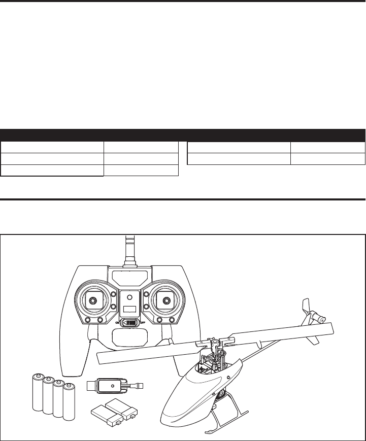
• Blade® mCP S Helicopter
• 2 210mAh 1S 3.7V 40C Li-Po Batteries
• USB 1S Li-Po Charger (RTF Only)
• MLP6DSM Transmitter (RTF Only)
• 4 AA Batteries (RTF Only)
Box Contents .................................................................... 3
First Flight Preparation ...................................................... 4
Flying Checklist ................................................................ 4
Charging Warnings............................................................ 4
Battery Charging ............................................................... 4
Installing the Transmitter Batteries (RTF) ........................... 5
Transmitter Control (RTF) .................................................. 5
Transmitter Setup (BNF) .................................................... 6
Installing the Flight Battery ...............................................8
Transmitter and Receiver Binding ...................................... 8
Throttle Hold .....................................................................9
Stunt Mode .......................................................................9
Control Tests ..................................................................... 9
Understanding the Primary Flight Controls ...................... 10
Flight Mode Description ..................................................11
Panic Recovery ............................................................... 11
Flying the mCP S ............................................................ 11
Post-Flight Inspection and Maintenance Checklist ........... 12
Troubleshooting Guide .................................................... 12
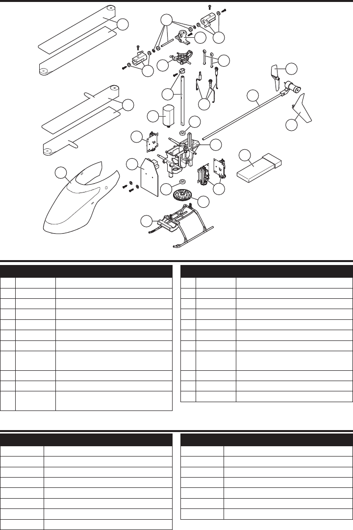
Exploded View ................................................................ 14
Parts Listings .................................................................. 14
Optional Parts ................................................................. 14
Limited Warranty ............................................................ 15
Warranty and Service Contact Information ...................... 16
FCC Information ..............................................................16
IC Information ................................................................. 16
Compliance Information for the European Union .............. 16
Box Contents
Table of Contents
To receive product updates, special offers and more, register your product at www.bladehelis.com.
Length 9.4 in (240mm)
Height 3.5 in (90 mm)
Main Rotor Diameter 9.4 in (240mm)
Tail Rotor Diameter 1.5 in (40mm)
Flying Weight 1.7 oz (49 g)
Specifications
4
EN
CAUTION: All instructions and warnings
must be followed exactly. Mishandling of Li-Po
batteries can result in a fi re, personal injury and/or
property damage.
• NEVER LEAVE CHARGING BATTERIES UNATTENDED.
• NEVER CHARGE BATTERIES OVERNIGHT.
• By handling, charging or using the included Li-Po battery,
you assume all risks associated with lithium batteries.
• If at any time the battery begins to balloon or swell, discon-
tinue use immediately. If charging or discharging, discontinue
and disconnect. Continuing to use, charge or discharge a
battery that is ballooning or swelling can result in fi re.
• Always store the battery at room temperature in a dry
area for best results.
• Always transport or temporarily store the battery in a
temperature range of 40–120º F (5–49° C).
• Do not store battery or model in a car or direct sunlight.
If stored in a hot car, the battery can be damaged or
even catch fi re.
• Always charge batteries away from fl ammable materials.
• Always inspect the battery before charging.
• Always disconnect the battery after charging, and
let the charger cool between charges.
• Always constantly monitor the temperature of the
battery pack while charging.
• ONLY USE A CHARGER SPECIFICALLY DESIGNED TO
CHARGE LI-PO BATTERIES. Failure to charge the battery
with a compatible charger may cause a fi re resulting in
personal injury and/or property damage.
• Never discharge Li-Po cells to below 3V under load.
• Never cover warning labels with hook and loop strips.
• Never charge batteries outside recommended levels.
• Never charge damaged batteries.
• Never attempt to dismantle or alter the charger.
• Never allow minors to charge battery packs.
• Never charge batteries in extremely hot or cold places
(recommended between 40–120° F or (5–49° C) or
place in direct sunlight.
Charging Warnings
First Flight Preparation
• Remove and inspect contents
• Begin charging the fl ight battery
• Program your computer transmitter (BNF only)
• Install the fl ight battery in the helicopter
(once it has been fully charged)
• Bind your transmitter (BNF only)
• Familiarize yourself with the controls
• Find a suitable area for fl ying
Flying Checklist
❏Always turn the transmitter on fi rst
❏ Plug the fl ight battery into the lead from the ESC
❏ Allow the receiver and ESC to initialize and arm properly
❏Fly the model
❏Land the model
❏ Unplug the fl ight battery from the ESC
❏Always turn the transmitter off last
Battery Charging
USB Li-Po
Charger
EFLC1013
SOLID RED LED
–Charging
DC Input:5.0V 500mA
DC Output:4.2V 500mA
LED OFF
–Charge
Complete
CAUTION: Only use chargers specifi cally designed
to charge the included Li-Po battery. Failure to do
so could result in fi re, causing injury or property damage.
CAUTION: Never exceed the recommended
charge rate.
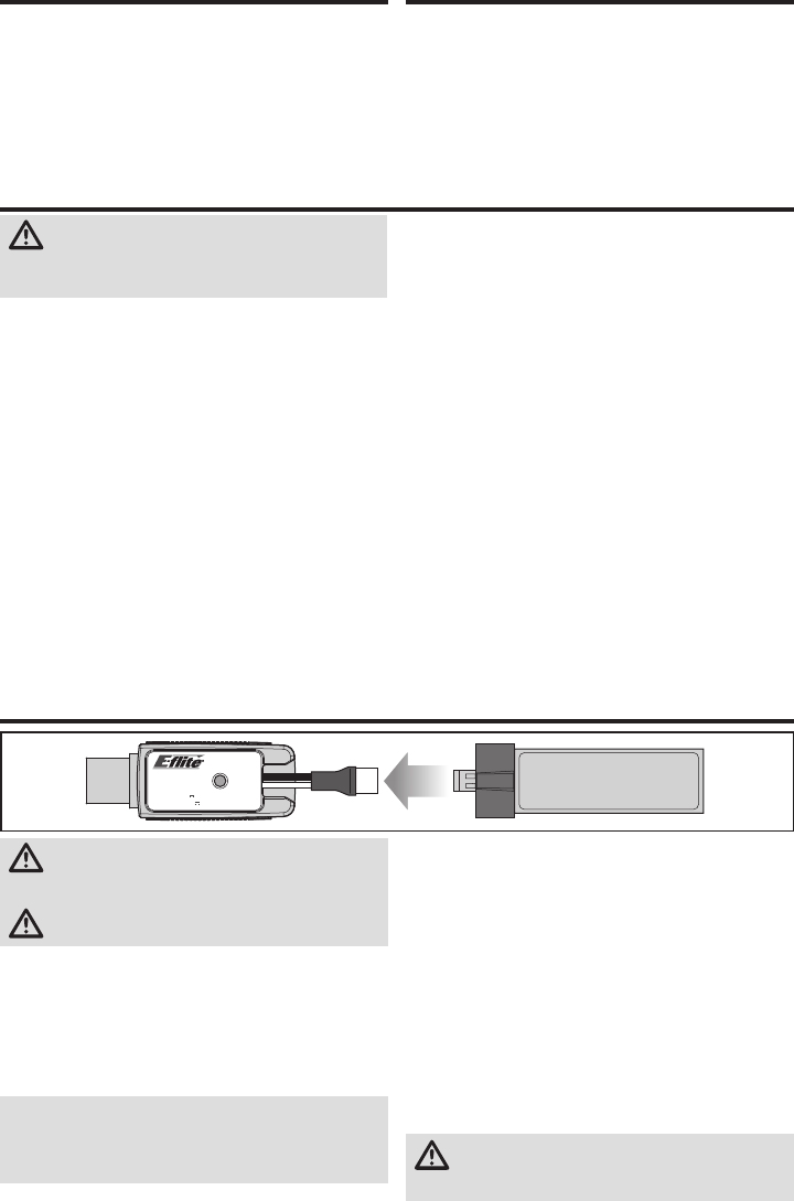
The USB battery charger (EFLC1013) included with your
aircraft has been designed to safely charge the 1S 3.7V
210mAh 40C Li-Po fl ight battery. Refer to the charging warn-
ings. It is recommended to charge the battery pack while you
are inspecting the aircraft. The fl ight battery will be required
to confi rm proper aircraft operation in future steps.
NOTICE: Inspect the battery to make sure it is not dam-
aged e.g., swollen, bent, broken or punctured. Charge only
batteries that are cool to the touch and are not damaged.
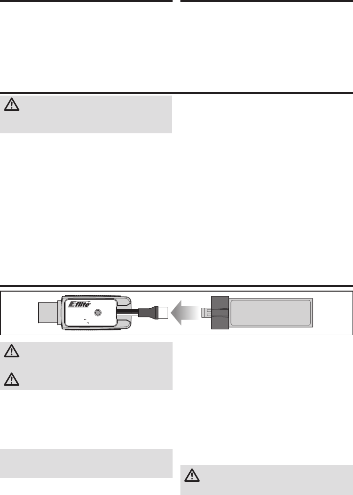
1. Insert the charger into a USB port. The charger only uses
power from the USB port. USB power supplies, such as
those used to charge cellular phones, can also be used.
2. Connect the battery to the charger as shown in the illustra-
tion above. When you make the connection successfully, the
LED on the charger turns solid red, indicating charging has
begun. Charging a fully discharged (not over-discharged)
210mAh battery takes approximately 30 minutes. The LED
goes out when the charge is complete.
CHARGING (Solid Red LED)
MAX CHARGE (LED OFF)
3. Always disconnect the fl ight battery from the charger
immediately upon completion of charging.
CAUTION: Once charging is complete,
immediately remove the battery. Never leave a
battery connected to the charger.

5EN
Installing the Transmitter Batteries (RTF)
The LED indicator fl ashes and the transmitter
beeps progressively faster as the battery voltage
drops.
Replace the transmitter batteries when the
transmitter begins to beep.
Transmitter Control (RTF)
D
E
C
B
Flight mode switch
E
Dual rate
switch
ABCDE F
Mode 1
Aileron (Left/Right)
Throttle/Collective
(Up/Down)
Throttle
Trim
Aileron
Trim
Rudder
Trim
Elevator
Trim
Rudder (Left/Right)
Elevator (Up/Down)
Mode 2 Aileron (Left/Right)
Elevator (Up/Down)
Elevator
Trim
Aileron
Trim
Rudder
Trim
Throttle
Trim
Rudder (Left/Right)
Throttle/Collective
(Up/Down)
ON/OFF
Switch
A
F
Adjusting Flight Trims
When pressed down, trim buttons make a sound that
increases or decreases in pitch at each pressing. The
middle or neutral trim position is heard as a middle tone in
the pitch range of the sounds. The end of the control range
is sounded by a series of beeps.
Dual Rate Selection
The control sensitivity can be changed by pressing and
releasing the right control stick. The LED on the transmitter
will show solid for high sensitivity (default) and fl ashing for
low sensitivity.
Bind switch
Panic Recovery
Power LED/fl ight
mode indicator
6
EN
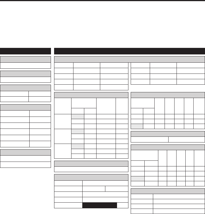
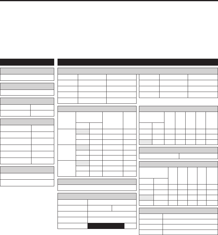
FUNCTION LIST
DX7s, DX8
F-Mode Setup
Flight Mode F Mode
Hold Hold
SETUP LIST
Swash Type
1 servo Normal
Model Type
HELI
SW Select
Trainer Aux 2
F Mode Gear
Gyro INH
Mix INH
Hold INH
Knob INH
Frame Rate
11ms
DSMX
D/R & Expo
Chan
Switch Pos
(Ail D/R)
D/R
ExpoDX7s
DX8
AILE
0 100/100 +25
0 1 100/100 +25
1 2 75/75 +25
ELEV
0 100/100 +25
0 1 100/100 +25
1 2 75/75 +25
RUDD
0 100/100 +25
0 1 100/100 +25
1 2 75/75 +25
Timer
Mode Count Down
Time 4:00 Tone
Start Throttle Out
Over 25%
Chan Travel Reverse
THR 100/100 Normal
AIL 100/100 Normal
ELE 100/100 Normal
RUD 100/100 Normal
Chan Travel Reverse
GER 100/100 Normal
PIT 100/100 Normal
AX2 100/100 Normal
Servo Setup
Throttle Curve
Switch Pos
(F Mode)
Pt 1 Pt 2 Pt 3 Pt 4 Pt 5DX7s DX8
N N 0 25 50 75 100
1 1 100 80 75 80 100
2 100 100 100 100 100
Pitch Curve
Switch Pos
(F Mode)
Pt 1 Pt 2 Pt 3 Pt 4 Pt 5DX7s DX8
N N 30 40 50 75 100
1 1 0 25 50 75 100
2 0 25 50 75 100
HOLD HOLD 25 37 50 75 100
Throttle Cut
Throttle 0%
Gyro
INH
Mixing
Channels AUX2 > GER
Rate 100% 20%
Offset 100%
Trim INH
Position NIHM
Panic Mode Operation
Trainer/Bind Button
Pressed = Panic Mode On
Released = Panic Mode Off
Program your transmitter before attempting to bind or fl y
the helicopter. Transmitter programming values are shown
below for the Spektrum DX7s, DX6, DX7, DX8, DX9, DX18
and DX20.
The fi les for models using Spektrum™ transmitters
with Spektrum AirWare™ software are also available for
download online at www.spektrumrc.com.
DXe
To use the Spektrum™ DXe transmitter, download the Blade®
mCP S DXe model setup available at www.spektrumrc.com
or use the appropriate programming cable and the PC or
mobile app to program the transmitter.
Transmitter Setup (BNF)
Flight Mode Operation
F MODE Sw: Pos 0 = Stability Mode
Pos 1 = Intermediate Mode
Pos 2 = Agility Mode
7EN
F-Mode Setup
Flight Mode F Mode
Hold Hold
SETUP LIST
Swash Type
1 servo Normal
Model Type
HELI
Timer
Mode Count Down
Time 4:00
Start Throttle Out
Over 25%
One Time Inhibit
Servo Setup
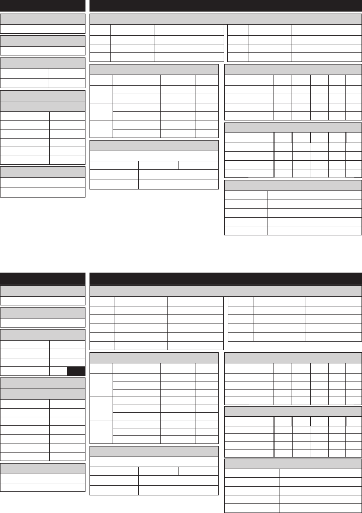
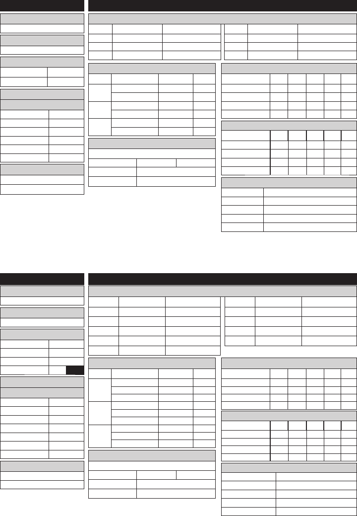
FUNCTION LIST
DX6, DX6e
Chan Travel Reverse
THR 100/100 Normal
AIL 100/100 Normal
ELE 100/100 Normal
Chan Travel Reverse
RUD 100/100 Normal
GER 100/100 Normal
PIT 75/75 Normal
D/R & Expo
Chan Switch (F) Pos D/R Expo
AILE 0 70/70 +30
1 100/100 +30
ELEV 0 70/70 +30
1 100/100 +30
RUDD 0 100/100 0
1 100/100 0
Throttle Curve
Switch (B) Pos Pt 1 Pt 2 Pt 3 Pt 4 Pt 5
N 0 40 60 80 100
1 100 90 80 90 100
2 100 100 100 100 100
HOLD 0 0 0 0 0
Pitch Curve
Switch (B) Pos Pt 1 Pt 2 Pt 3 Pt 4 Pt 5
N 30 40 50 75 100
1 0 25 50 75 100
2 0 25 50 75 100
HOLD 0 25 50 75 100
* The DX6e operates
at 22ms frame rate and
cannot be changed.
Frame Rate
11ms*
DSMX
Frame Rate
11ms*
DSMX
Chan Travel Reverse
THR 100/100 Normal
AIL 100/100 Normal
ELE 100/100 Normal
RUD 100/100 Normal
GER 100/100 Normal
Chan Travel Reverse
PIT 75/75 Normal
AX2 100/100 Normal
AX3 100/100 Normal
AX4 100/100 Normal
Servo Setup
FUNCTION LIST
DX7G2, DX8G2, DX9, DX18, DX20
Timer
Mode Count Down
Time 4:00
Start Throttle Out
Over 25%
One Time Inhibit
SYSTEM SETUP
Swash Type
1 servo Normal
Model Type
HELI
F-Mode Setup
Switch 1 Switch B
Switch 2 Inhibit
Hold Switch Switch H
01
D/R & Expo
Chan Switch (F) Pos D/R Expo
AILE 0 70/70 +30
1 100/100 +30
2 100/100 +30
ELEV 0 70/70 +30
1 100/100 +30
2 100/100 +30
RUDD 0 100/100 0
1 100/100 0
2 100/100 0
Throttle Curve
Switch (B) Pos Pt 1 Pt 2 Pt 3 Pt 4 Pt 5
N 0 40 60 80 100
1 100 90 80 90 100
2 100 100 100 100 100
HOLD 0 0 0 0 0
Pitch Curve
Switch (B) Pos Pt 1 Pt 2 Pt 3 Pt 4 Pt 5
N 30 40 50 75 100
1 0 25 50 75 100
2 0 25 50 75 100
HOLD 0 25 50 75 100
Channel Assign
Channel Input Confi g
1 Throttle Throttle
2 Aileron Aileron
3 Elevator Elevator
4 Rudder Rudder
5 Gear Switch B
6 AUX 1 INH
Channel Assign
Channel Input Confi g
1 Throttle Throttle
2 Aileron Aileron
3 Elevator Elevator
4 Rudder Rudder
5 Gear Switch B
6 AUX 1 INH
7 AUX 2 Mixing
GER -> GER
Rate 100% 100%
Offset 20%
Switch Switch I
Mixing
GER -> GER
Rate 100% 100%
Offset 20%
Switch Switch I
Panic Mode Operation
Bind / I Button: Pressed = Panic Mode On
Released = Panic Mode Off
Flight Mode Operation
Sw B: Pos 0 = Stability Mode
Pos 1 = Intermediate Mode
Pos 2 = Agility Mode
Panic Mode Operation
Bind / I Button
Pressed = Panic Mode On
Released = Panic Mode Off
Flight Mode Operation
Sw B: Pos 0 = Stability Mode
Pos 1 = Intermediate Mode
Pos 2 = Agility Mode
8
EN
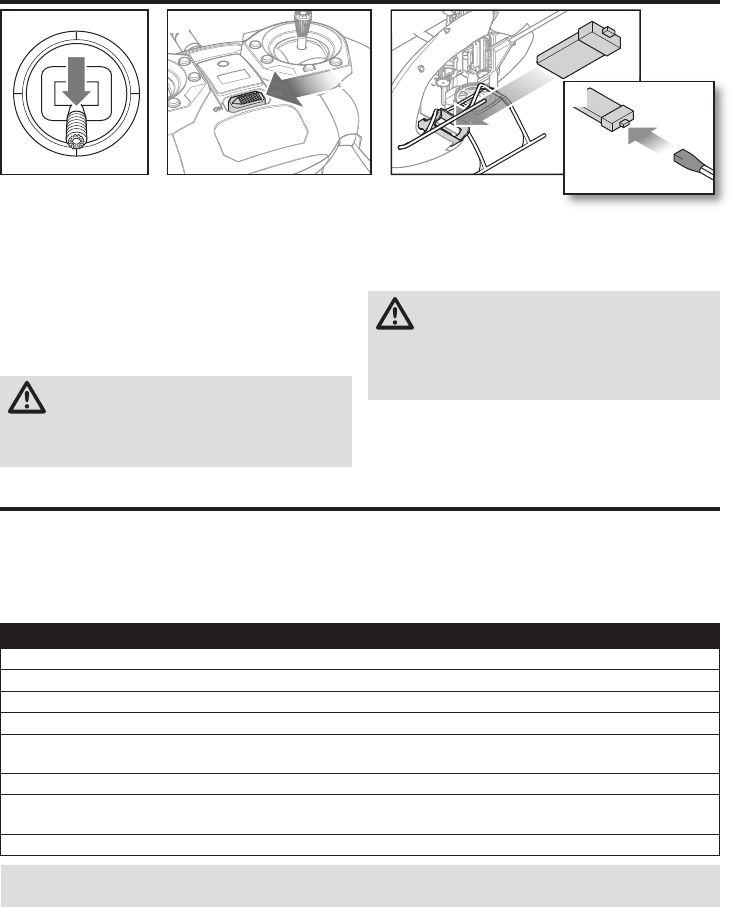
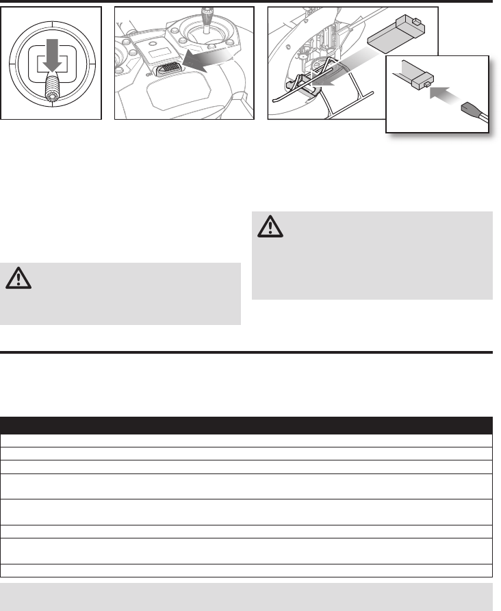
1. Lower the throttle stick to the lowest position.
2. Power ON the transmitter.
3. Center all trims. For the included MLP6 transmitter
(RTF only), the trims are centered when you hear a
longer tone while pressing the trim button. Move the
trim in both directions until you hear the long tone.
4. Install the fl ight battery in the battery holder on the
bottom of the helicopter frame.
5. Connect the fl ight control power lead to the battery
connector.
CAUTION: Connecting the battery to the fl ight
control board with reversed polarity will cause
damage to the control board, the battery or both. Dam-
age caused by incorrectly connecting the battery is not
covered under warranty.
6. Place the helicopter on a
fl at surface and leave it still
until the receiver LED glows solid,
indicating initialization is complete.
If you experience problems during initialization, refer to the
Troubleshooting Guide at the back of the manual.
CAUTION: Always disconnect the Li-Po battery
from the aircraft when not fl ying to avoid
over-discharging the battery. Batteries discharged to a
voltage lower than the lowest approved voltage may
become damaged, resulting in loss of performance and
potential fi re when batteries are charged.
Installing the Flight Battery
1 2 4
5
Transmitter and Receiver Binding
Binding Procedure for the MLP6DSM (RTF)
1. Disconnect the fl ight battery from the helicopter.
2. Power off the transmitter and move all switches to the 0 position.
3. Connect the fl ight battery to the helicopter. The 3-in-1 Control unit LED fl ashes after 5 seconds.
4. Push and hold the “panic” trigger/button and hold the rudder control stick to full left while powering on the transmitter.
5. Release the trainer switch/button. Continue to hold the rudder control stick to full left until the blue LED on the 3-in-1
control unit is solid.
6. Release the rudder control stick.
7. Push the trainer switch/button. The blue LED on the 3-in-1 control unit fl ashes to confi rm the helicopter is in
non-computer mode.
8. Disconnect the fl ight battery and power the transmitter off.
NOTICE: If the swashplate moves up and down when the trainer switch is moved, the helicopter is in computer
transmitter mode. Repeat the binding procedure.
Binding is the process of programming the receiver of the control unit to recognize the GUID (Globally Unique Identifi er)
code of a single specifi c transmitter. You need to ‘bind’ your chosen Spektrum™ DSM2 ®/ DSMX ® technology equipped
aircraft transmitter to the receiver for proper operation.
If you purchased an RTF model, the transmitter is bound to the model at the factory.
If for any reason you need to re-bind your mCP S to the MLP6DSM, follow the directions below:
9EN
Stunt Mode
Stunt Mode (Flight Mode 1 or 2) allows the helicopter to fl y
inverted and perform aerobatics. The throttle runs continuously
when Stunt Mode is ON, regardless of throttle stick position.
Turn Stunt Mode OFF (Flight Mode 0) to return full control to the
throttle stick.
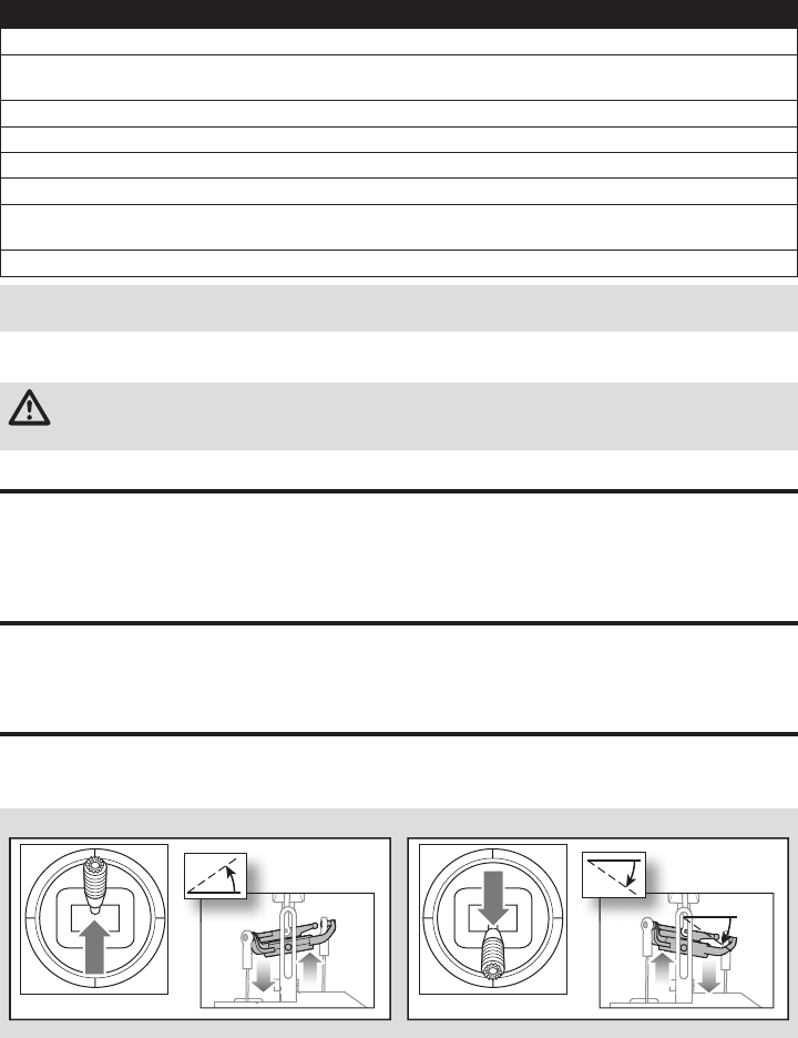
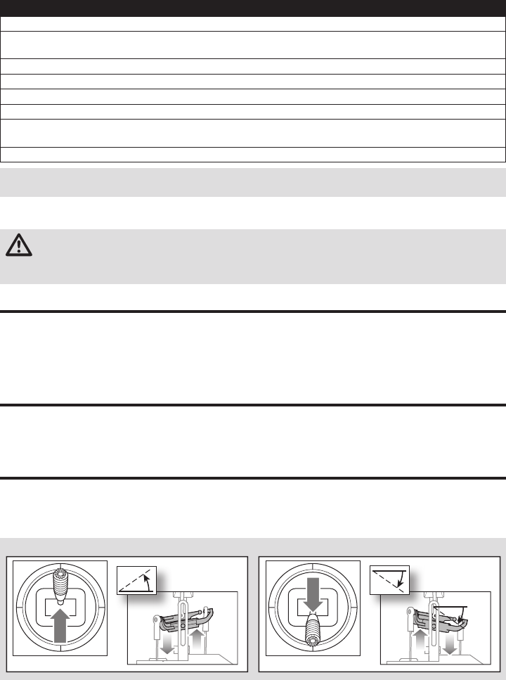
Elevator
Elevator down Elevator up
Left Side View Left Side View
Control Tests
Ensure the throttle hold is ON when doing the direction
control tests. Test the controls prior to the fi rst fl ight to
ensure the servos, linkages and parts operate correctly.
If the controls do not react as shown in the illustrations
below, confi rm the transmitter is programmed correctly
before continuing on to the Motor test.
CAUTION: When using a Futaba® transmitter with a Spektrum™ DSM2® module, you must reverse the throttle
channel and re-bind. Refer to your Spektrum module manual for binding and failsafe instructions. Refer to your
Futaba transmitter manual for instructions on reversing the throttle channel.
Throttle hold is used to prevent the motor from powering on
inadvertently. For safety, turn throttle hold ON any time you
need to touch the helicopter or check the direction controls.
Throttle hold is also used to turn off the motor quickly if the
helicopter is out of control, in danger of crashing, or both.
The blades will continue to spin briefl y when throttle hold is
activated. Pitch and direction control is still maintained.
Throttle Hold
Binding Procedure for Computer Radios (BNF)
1. Disconnect the fl ight battery from the helicopter.
2. If you are not using the transmitter included with the RTF version of the helicopter, refer to the Transmitter Setup
Table to correctly program your transmitter.
3. Lower the throttle stick to the lowest position. Set all trims to the center position while the transmitter is on.
4. Power off the transmitter and move all switches to the 0 position. Move the throttle to the low/off position.
5. Connect the fl ight battery to the ESC. The receiver LED fl ashes, indicating it is in bind mode.
6. Po wer on the transmitter in bind mode.
7. Move the rudder control stick to full right. Continue to hold the rudder control stick to full right until the blue LED on
the 3-in-1 control unit is solid. The helicopter is bound when the LED on the receiver turns solid.
8. Disconnect the fl ight battery and power the transmitter off.
NOTICE: The throttle will not arm if the transmitter’s throttle control is not put at the lowest position and the stunt
mode switch is not in the 0 position.
If you encounter problems, refer to the troubleshooting guide for other instructions. If needed, contact the appropriate
Horizon Hobby Product Support offi ce.
This product requires an approved Spektrum DSM2®/DSMX® compatible transmitter.
To bind your mCP S to your chosen transmitter, follow the directions below:
10
EN
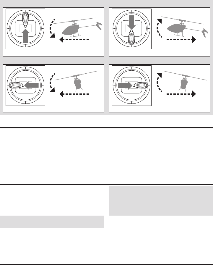
Descend
Nose Yaws Left
Rudder left
Throttle up
Rudder right
Throttle down
Climb
Collective
Rudder
Left Side View Left Side View
Top ViewTop View
Nose Yaws Right
Understanding the Primary Flight Controls
If you are not familiar with the controls of the mCP S, take a few minutes to familiarize yourself with them before
attempting your fi rst fl ight.
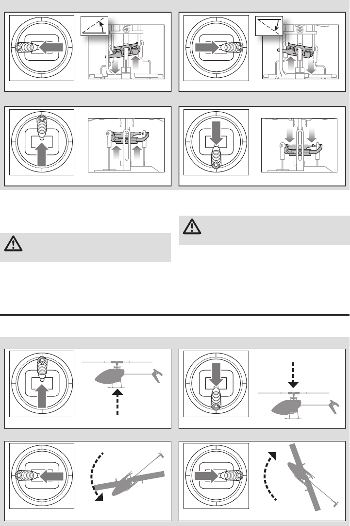
Left Side View Left Side View
Collective Pitch
Collective pitch up Collective pitch down
Motor
Place the helicopter outdoors on a clean, fl at and level
surface (concrete or asphalt) free of obstructions. Always
stay clear of moving rotor blades.
CAUTION: Keep pets and other animals away
from the helicopter. Animals may injure themselves
if they attack or run toward the helicopter.
1. Both motors beep 3 times when the helicopter’s control
unit arms properly. Before you continue, confi rm that
throttle is at full low position.
2. Turn Throttle Hold OFF.
WARNING: Stay at least 30 feet (10 meters) away
from the helicopter when the motor is running. Do
not attempt to fl y the helicopter at this time.
3. Slowly increase the throttle until the blades begin to
spin. The main blades should spin clockwise when
viewing the helicopter from the top. The tail rotor
blades should spin counterclockwise when viewing the
helicopter from the right side.
Aileron
Aileron left Aileron right
Rear View Rear View
11 EN
In Stability Mode the helicopter fl ies similarly to a fi xed-
pitch helicopter (the bank angle is limited). When the cyclic
stick is released, the model will return to level.
In Intermediate Mode the bank angle is not limited. When
the cyclic stick is released the model will not return to
level. The head speed is slightly lower and the controls
have a "softer" feel. This mode is great for learning forward
fl ight and basic aerobatics, such as stall turns and loops.
In Agility Mode the bank angle is not limited. When the
cyclic stick is released the model will not return to level. The
head speed is also higher. This mode is great for 3D aerobat-
ics, such as stationary fl ips and tic tocs.
Flight Mode Description
Consult your local laws and ordinances before
choosing a location to fl y your aircraft.
If this is your fi rst collective pitch helicopter, we suggest
getting assistance from an experienced helicopter pilot or
fl ying club until you are comfortable fl ying alone.
We recommend fl ying your aircraft outside in calm winds
or inside a large gymnasium. Always avoid fl ying near
houses, trees, wires and buildings. You should also be
careful to avoid fl ying in areas where there are many
people, such as busy parks, schoolyards or soccer fi elds.
It is best to fl y from a smooth fl at surface as this will allow
the model to slide without tipping over. Keep the helicopter
approximately 2 ft (600mm) above the ground. Keep the
tail pointed toward you during initial fl ights to keep the
control orientation consistent. Releasing the stick in Stabil-
ity Mode will allow the helicopter to level itself. Activating
the Panic Recovery button will level the helicopter quickly.
If you become disoriented while in Stability Mode, slowly
lower the throttle stick to land softly.
During initial fl ights, only attempt takeoff, landing and
hovering in one spot.
If you get into distress while fl ying in any mode, push and
hold the Bind/Panic Switch and move the control sticks to
their neutral position. SAFE® technology will immediately
return the aircraft to an upright level attitude, if the aircraft is
at a suffi cient height with no obstacles in its path.
NOTICE: Do not activate Panic Recovery if the helicopter
does not have suffi cient altitude for a succesful recovery.
Return the collective stick to 50% and release the Panic
Switch to turn off Panic Recovery and return to the current
fl ight mode.
NOTICE: Before releasing the panic switch, make
sure the collective stick has been returned to the 50%
position. Once the panic switch has been released, full
negative collective becomes available, which could
cause the mCP S to descend rapidly.
• Panic Recovery is intended to provide the pilot with the
confi dence to continue to improve their fl ight skills.
• Move the collective stick to 50% and return all other
transmitter controls to neutral for the quickest recovery.
• Once the model has reached a level upright attitude, the
negative collective is reduced to prevent the user from
pushing the model into the ground.
Panic Recovery
Forward
Left
Backward
Right
Elevator forward
Aileron left
Elevator back
Aileron right
Elevator
Aileron
Left Side View
Rear ViewRear View
Left Side View
Flying the mCP S
12
EN
Problem Possible Cause Solution
Helicopter control response
is inconsistent or requires
extra trim to neutralize
movement
Aircraft was not initialized properly
or a vibration is interfering with the
sensor operation
Disconnect the fl ight battery, center the control trim and
re-initialize the helicopter
Helicopter will not
respond to throttle
Throttle too high and/or throttle trim
is too high
Disconnect the fl ight battery, place the throttle stick in the
lowest position and lower the throttle trim a few clicks.
Connect the fl ight battery and allow the model to initialize
Helicopter moved during initialization Disconnect the flight battery and re-initialize the helicopter
while keeping the helicopter from moving
Takeo
IMPORTANT: If the main motor or tail motor do not startup
properly when throttle is fi rst applied, immediately return
the throttle to idle and try again. If the problem persists,
disconnect the fl ight battery, check for binding in the gear
train and ensure no wires have become entangled within
the gears.
Place the model onto a fl at, level surface free of obstacles
and walk back 30 feet (10 meters). Slowly increase the
throttle until the model is approximately 2 ft. (600mm)
off the ground and check the trim so the model fl ies as
desired. Once the trim is adjusted, begin fl ying the model.
Hovering
Making small corrections on the transmitter, try to hold the
helicopter in one spot. If fl ying in calm winds, the model
should require almost no corrective inputs. After moving
the cyclic stick and returning it to center, the model
should level itself. The model may continue to move due
to inertia. Move the cycle stick in the opposite direction to
stop the movement.
After you become comfortable hovering, you can progress
into fl ying the model to different locations, keeping the tail
pointed towards you at all times. You can also ascend and
descend using the throttle stick. Once you’re comfortable
with these maneuvers, you can attempt fl ying with the tail
in different orientations. It is important to keep in mind
that the fl ight control inputs will rotate with the helicopter,
so always try to picture the control inputs relative to the
nose of the helicopter. For example, forward will always
drop the nose of the helicopter.
The average fl ight time of the helicopter using the recom-
mended battery is approximately 4 minutes, depending on
how aggressively the aircraft is fl own.
Low Voltage Cuto (LVC)
LVC decreases the power to the motors when the battery
voltage gets low. When the motor power decreases and
the LED on the ESC fl ashes, land the aircraft immediately
and recharge the fl ight battery.
LVC does not prevent the battery from over-discharge
during storage.
NOTICE: Repeated fl ying to LVC may damage the battery.
Landing
To land, slowly decrease the throttle while in a low-level
hover. After landing, disconnect and remove the battery
from the aircraft after use to prevent trickle discharge. Fully
charge your battery before storing it. During storage, make
sure the battery charge does not fall below 3V per cell.
Troubleshooting Guide
Post-Flight Inspection and Maintenance Checklist
Ball Links Make sure the plastic ball link holds the control ball, but is not tight (binding) on the ball. When a link is too loose on
the ball, it can separate from the ball during fl ight and cause a crash. Replace worn ball links before they fail.
Cleaning Make sure the battery is not connected before cleaning. Remove dust and debris with a soft brush or a dry,
lint-free cloth.
BearingsReplace bearings when they become notchy (sticky in places when turning) or draggy.
Wiring Make sure the wiring does not contact moving parts. Replace damaged wiring and loose connectors.
Fasteners Make sure there are no loose screws, other fasteners or connectors. Do not over-tighten metal screws in plastic
parts. Tighten screws so the parts are mated together, then turn the screw only 1/8th of a turn more.
Rotors
Make sure there is no damage to rotor blades and other parts which move at high speed. Damage to these parts
includes cracks, burrs, chips or scratches. Replace damaged parts before fl ying. Verify both main rotor blades have
the correct and equal tension in the blade grips. When the helicopter is held up sideways, the main blades should
support their own weight. When the helicopter is shaken lightly, the blades should fall.
Tail Inspect the tail rotor for damage and replace if necessary. Inspect the tail boom for any damage and replace if necessary.
Mechanics Inspect the main frame and landing gear for damage and replace if necessary. Check the mainshaft for vertical
play. Verify that the main gear mesh is correct and that no tight spots exist in the 360 degree rotation. Inspect
all wires for damage. Replace components as necessary.

13 EN
Problem Possible Cause Solution
Helicopter has
reduced fl ight time
or is underpowered
Flight battery charge is low Completely recharge the fl ight battery
Flight battery is damaged
Replace the fl ight battery and follow the fl ight battery instructions
Flight conditions might be too cold Make sure the battery is warm (room temperature) before use
LED on the fl ight control
board fl ashes rapidly and
aircraft will not respond to
transmitter (during binding)
Transmitter too near aircraft during
binding process
Power off the transmitter. Move the transmitter a larger
distance from the aircraft. Disconnect and reconnect the
fl ight battery to the aircraft. Follow the binding instructions
Bind switch or button was not held
while transmitter was powered on Power off transmitter and repeat bind process
Aircraft or transmitter is too close to
large metal object, wireless source
or another transmitter
Move aircraft and transmitter to another
location and attempt binding again
LED on the fl ight control
board fl ashes rapidly and
the helicopter will not
respond to the transmitter
(after binding)
Less than a 5-second wait
between fi rst powering on the
transmitter and connecting the
fl ight battery to the helicopter
Leave the transmitter powered on. Disconnect and
reconnect the fl ight battery to the helicopter
The helicopter is bound to a
different model memory
(ModelMatch™ transmitters only)
Select the correct model memory on the transmitter.
Disconnect and reconnect the fl ight battery to the helicopter
Flight battery or transmitter
battery charge is too low Replace or recharge batteries
Aircraft or transmitter is too close to
large metal object, wireless source
or another transmitter
Move aircraft and transmitter to another
location and attempt connecting again
Helicopter vibrates or
shakes in fl ight Damaged rotor blades, spindle or
blade grips Check main rotor blades and blade grips for cracks or
chips. Replace damaged parts. Replace bent spindle
Random movements
in fl ight Vibration
Verify the receiver is properly attached to the helicopter. Inspect
and balance all rotating components. Verify the main shaft
and tail rotor are not damaged or bent. Inspect mechanics for
broken or damaged parts and replace as necessary
Tail oscillation/wag or poor
performance
Damaged tail rotor, tailboom, main
gear mesh, main shaft, loose bolts,
vibration
Inspect the tail rotor for damage. Inspect the tail boom and
main shaft for cracks. Verify main gear mesh and ensure no
tight spots in the mesh through full rotation. Replace any dam-
aged or worn components
Drift in calm winds Vibration, damaged linkage,
damaged servo
Under normal operation the transmitter trims should not
require adjustment and the center positions are memorized
during initialization. If you fi nd that trim adjustments are
necessary after take off, verify the balance of all rotating
components, ensure the linkages are not damaged and
make sure the servos are in proper working condition
Drift in wind Normal
The model will drift with the wind but should remain level
in fl ight. Simply hold the cyclic stick in the necessary posi-
tion to keep the model stationary. The model must lean
into the wind to remain stationary. If the model remains
level then it will drift with the wind
Panic recovery or return
to level does not level the
model
Model was not initialized on a level,
still surface Re-initialize the model on a level and still surface
Model was not taken off of a level
surface Always lift off from a level surface
Severe vibration
Main shaft cracked Check the main shaft for cracks and replace if necessary
Rotating component out of balance
Check the main shaft, tail rotor, main rotor blades, main
frame and adapter for damage, replace as necessary.
Vibration must be minimized for "panic recovery" and
return to level functions to work properly
14
EN
Part # Description
1 BLH3503 Main Motor with Pinion
2 BLH3504 Landing Skid & Batt Mount
3 BLH3505 Main Frame with Hardware
4 BLH3506 Main Gear
5 BLH3507 Main Shaft w/Collar & Hardware
6 BLH3508 Pushrod Set w/Ball Link:3pcs
7 BLH3509 Complete Precision Swashplate
8 BLH3510 Hi-Performance Main Rotor Blades
w/Hardware
9 BLH3511 Fast Flight Main Rotor Blades w/Hdwe
10 BLH3512 Main Rotor Hub w/Hdwe
11 BLH3513 Feathering Spindle w/o-ring,
Bushing, & Hardware
Part # Description
12 BLH3514 MnBlade Grips with Bearings
13 BLH3522 Rotor Head Linkage Set (8)
14 BLH3602 Tailboom Assembly
15 BLH3603 Tail Rotor
16 BLH5101 3 n 1 Flybarelss Control Unit
17 BLH5103 Red Canopy w/Vertical Fin
18 EFLH2215 OuterShaft Bearing 3x6x2mm(2)
19
SPMSH2025L
2.0-Gram Performance Linear
Long Throw Servo, 15mm Lead
20
EFLB2101S40
210mAh 1S 3.7V 40C LiPo Battery
EFLC1013
1S USB Li-Po Charger, 500mAh
EFLRMLP6 MLP6DSM 6CH SAFE Tx (RTF Only)
Part # Description
BLH3519 ComplGrCanopyw/VertFin
BLH3602L Long TailBoomAssy
BLH3603GR Green Tail Rotor (1)
BLH3603OR Orange Tail Rotor (1)
BLH3603YE Yellow Tail Rotor (1)
EFLA7002UM 1s HiCurrentUM Batt Adptr Lead
EFLB2001S30 200mAh 1S 3.7V 30C LiPo Battery
EFLC1004 Celctra4Port1C 3.7V0.3ADCLiPoChar
Part # Description
EFLH3023 CarbnFibrTrainingGearSet
SPM20000 DX20 20 CH System w/ AR9020 M2
SPM6650 DX6e 6CH System w/ AR610 RX
SPM6750 DX6 System MD2
SPMR1000 DXe Transmitter Only
SPMR8000 DX8 Transmitter Only MD2
SPMR9910 DX9 Black Transmitter Only MD2
Parts Listings
Optional Parts
8
9
1
11
10
13
12
12
5
7
19
16
20
18
3
18
17
2
4
17
14
15
6
19
Exploded View

15 EN
What this Warranty Covers
Horizon Hobby, LLC, (Horizon) warrants to the original pur-
chaser that the product purchased (the “Product”) will be
free from defects in materials and workmanship at the date
of purchase.
What is Not Covered
This warranty is not transferable and does not cover (i) cosmetic
damage, (ii) damage due to acts of God, accident, misuse,
abuse, negligence, commercial use, or due to improper use,
installation, operation or maintenance, (iii) modification of or to
any part of the Product, (iv) attempted service by anyone other
than a Horizon Hobby authorized service center, (v) Product not
purchased from an authorized Horizon dealer, (vi) Product not
compliant with applicable technical regulations, or (vii) use that
violates any applicable laws, rules, or regulations.
OTHER THAN THE EXPRESS WARRANTY ABOVE, HORIZON
MAKES NO OTHER WARRANTY OR REPRESENTATION, AND
HEREBY DISCLAIMS ANY AND ALL IMPLIED WARRANTIES,
INCLUDING, WITHOUT LIMITATION, THE IMPLIED
WARRANTIES OF NON-INFRINGEMENT, MERCHANTABILITY
AND FITNESS FOR A PARTICULAR PURPOSE. THE
PURCHASER ACKNOWLEDGES THAT THEY ALONE HAVE
DETERMINED THAT THE PRODUCT WILL SUITABLY MEET THE
REQUIREMENTS OF THE PURCHASER’S INTENDED USE.
Purchaser’s Remedy
Horizon’s sole obligation and purchaser’s sole and exclusive
remedy shall be that Horizon will, at its option, either (i) service,
or (ii) replace, any Product determined by Horizon to be defective.
Horizon reserves the right to inspect any and all Product(s) involved
in a warranty claim. Service or replacement decisions are at the
sole discretion of Horizon. Proof of purchase is required for all war-
ranty claims. SERVICE OR REPLACEMENT AS PROVIDED UNDER
THIS WARRANTY IS THE PURCHASER’S SOLE AND EXCLUSIVE
REMEDY.
Limitation of Liability
HORIZON SHALL NOT BE LIABLE FOR SPECIAL, INDIRECT,
INCIDENTAL OR CONSEQUENTIAL DAMAGES, LOSS OF
PROFITS OR PRODUCTION OR COMMERCIAL LOSS IN ANY
WAY, REGARDLESS OF WHETHER SUCH CLAIM IS BASED IN
CONTRACT, WARRANTY, TORT, NEGLIGENCE, STRICT LIABILITY OR
ANY OTHER THEORY OF LIABILITY, EVEN IF HORIZON HAS BEEN
ADVISED OF THE POSSIBILITY OF SUCH DAMAGES. Further, in no
event shall the liability of Horizon exceed the individual price of the
Product on which liability is asserted. As Horizon has no control
over use, setup, final assembly, modification or misuse, no liability
shall be assumed nor accepted for any resulting damage or injury.
By the act of use, setup or assembly, the user accepts all resulting
liability. If you as the purchaser or user are not prepared to accept
the liability associated with the use of the Product, purchaser is
advised to return the Product immediately in new and unused
condition to the place of purchase.
Law
These terms are governed by Illinois law (without regard to
conflict of law principals). This warranty gives you specific
legal rights, and you may also have other rights which vary
from state to state. Horizon reserves the right to change or
modify this warranty at any time without notice.
WARRANTY SERVICES
Questions, Assistance, and Services
Your local hobby store and/or place of purchase cannot
provide warranty support or service. Once assembly, setup
or use of the Product has been started, you must contact
your local distributor or Horizon directly. This will enable
Horizon to better answer your questions and service you in
the event that you may need any assistance. For questions
or assistance, please visit our website at www.horizonhobby.
com, submit a Product Support Inquiry, or call the toll free
telephone number referenced in the Warranty and Service
Contact Information section to speak with a Product Support
representative.
Inspection or Services
If this Product needs to be inspected or serviced and is com-
pliant in the country you live and use the Product in, please
use the Horizon Online Service Request submission process
found on our website or call Horizon to obtain a Return
Merchandise Authorization (RMA) number. Pack the Product
securely using a shipping carton. Please note that original
boxes may be included, but are not designed to withstand
the rigors of shipping without additional protection. Ship via
a carrier that provides tracking and insurance for lost or
damaged parcels, as Horizon is not responsible for merchan-
dise until it arrives and is accepted at our facility. An Online
Service Request is available at http://www.horizonhobby.com/
content/service-center_render-service-center. If you do not
have internet access, please contact Horizon Product Support
to obtain a RMA number along with instructions for submit-
ting your product for service. When calling Horizon, you will
be asked to provide your complete name, street address,
email address and phone number where you can be reached
during business hours. When sending product into Horizon,
please include your RMA number, a list of the included items,
and a brief summary of the problem. A copy of your original
sales receipt must be included for warranty consideration. Be
sure your name, address, and RMA number are clearly writ-
ten on the outside of the shipping carton.
NOTICE: Do not ship Li-Po batteries to Horizon. If you have
any issue with a Li-Po battery, please contact the appropriate
Horizon Product Support office.
Warranty Requirements
For Warranty consideration, you must include your
original sales receipt verifying the proof-of-purchase
date. Provided warranty conditions have been met, your
Product will be serviced or replaced free of charge. Service
or replacement decisions are at the sole discretion of Horizon.
Non-Warranty Service
Should your service not be covered by warranty, ser-
vice will be completed and payment will be required
without notification or estimate of the expense unless
the expense exceeds 50% of the retail purchase cost.
By submitting the item for service you are agreeing to pay-
ment of the service without notification. Service estimates are
available upon request. You must include this request with
your item submitted for service. Non-warranty service esti-
mates will be billed a minimum of ½ hour of labor. In addition
you will be billed for return freight. Horizon accepts money
orders and cashier’s checks, as well as Visa, MasterCard,
American Express, and Discover cards. By submitting any
item to Horizon for service, you are agreeing to Horizon’s
Terms and Conditions found on our website http://www.hori-
zonhobby.com/content/service-center_render-service-center.
ATTENTION: Horizon service is limited to Product
compliant in the country of use and ownership.
If received, a non-compliant Product will not be
serviced. Further, the sender will be responsible
for arranging return shipment of the un-serviced
Product, through a carrier of the sender’s choice
and at the sender’s expense. Horizon will hold non-
compliant Product for a period of 60 days from noti-
fication, after which it will be discarded. 10/15
Limited Warranty
16
EN
RTF Transmitter FCC ID: BRWDXMTX10
Helicopter FCC ID: BRWBLH5100
This equipment has been tested and found to comply with the limits for Part 15 of the FCC rules. These limits are designed
to provide reasonable protection against harmful interference in a residential installation. This equipment generates uses
and can radiate radio frequency energy and, if not installed and used in accordance with the instructions, may cause harmful
interference to radio communications.
However, there is no guarantee that interference will not occur in a particular installation. If this equipment does cause
harmful interference to radio or television reception, which can be determined by turning the equipment off and on, the
user is encouraged to try to correct the interference by one or more of the following measures:
• Reorient or relocate the receiving antenna.
• Increase the separation between the equipment and receiver.
• Connect the equipment to an outlet on a circuit different from that to which the receiver is connected.
This device complies with part 15 of the FCC rules. Operation is subject to the following two conditions: (1) This device
may not cause harmful interference, and (2) this device must accept any interference received, including interference that
may cause undesired operation.
NOTICE: Modifi cations to this product will void the user’s authority to operate this equipment.
FCC Information
IC Information
RTF Transmitter IC: 6157A-BRWDXMT
Helicopter IC: 6157A-BLH5100
This device complies with Industry Canada licence-exempt RSS standard(s). Operation is subject to the following two
conditions: (1) this device may not cause interference, and (2) this device must accept any interference, including
interference that may cause undesired operation of the device.”
Compliance Information for the European Union
EU Compliance Statement:
Horizon Hobby, LLC hereby declares that this
product is in compliance with the essential
requirements and other relevant provisions of the RED and
EMC Directives.
A copy of the EU Declaration of Conformity is available
online at: http://www.horizonhobby.com/content/support-
render-compliance.
Instructions for disposal of WEEE by users in the European Union
This product must not be disposed of with
other waste. Instead, it is the user’s respon-
sibility to dispose of their waste equipment
by handing it over to a designated collections
point for the recycling of waste electrical and
electronic equipment. The separate collection
and recycling of your waste equipment at the
time of disposal will help to conserve natural resources and
make sure that it is recycled in a manner that protects human
health and the environment. For more information about where
you can drop off your waste equipment for recycling, please
contact your local city offi ce, your household waste disposal
service or where you purchased the product.
Country of Purchase Horizon Hobby Contact Information Address
United States
of America
Horizon Service Center
(Repairs and Repair Requests) servicecenter.horizonhobby.com/RequestForm/
4105 Fieldstone Rd
Champaign, Illinois, 61822 USA
Horizon Product Support
(Product Technical Assistance)
productsupport@horizonhobby.com
877-504-0233
Sales websales@horizonhobby.com
800-338-4639
European Union Horizon Technischer Service service@horizonhobby.eu Hanskampring 9
D 22885 Barsbüttel, Germany
Sales: Horizon Hobby GmbH +49 (0) 4121 2655 100
Warranty and Service Contact Information

17 DE
Die folgenden Begriffe werden in der gesamten Produktliteratur verwendet, um auf unterschiedlich hohe
Gefahrenrisiken beim Betrieb dieses Produkts hinzuweisen:
WARNUNG: Wenn diese Verfahren nicht korrekt befolgt werden, ergeben sich wahrscheinlich Sachschäden,
Kollateralschäden und schwere Verletzungen ODER mit hoher Wahrscheinlichkeit oberfl ächliche Verletzungen.
ACHTUNG: Wenn diese Verfahren nicht korrekt befolgt werden, ergeben sich wahrscheinlich Sachschäden UND die
Gefahr von schweren Verletzungen.
HINWEIS: Wenn diese Verfahren nicht korrekt befolgt werden, können sich möglicherweise Sachschäden UND geringe
oder keine Gefahr von Verletzungen ergeben.
• Halten Sie stets in allen Richtungen einen Sicherhe-
itsabstand um Ihr Modell, um Zusammenstöße oder
Verletzungen zu vermeiden. Dieses Modell wird von
einem Funksignal gesteuert, das Interferenzen von vielen
Quellen außerhalb Ihres Einfl ussbereiches unterliegt.
Diese Interferenzen können einen augenblicklichen
Steuerungsverlust verursachen.
• Betreiben Sie Ihr Modell immer auf einer Freifl äche ohne
Fahrzeuge in voller Größe, Verkehr oder Menschen.
• Befolgen Sie stets sorgfältig die Anweisungen und
Warnhinweise für das Modell und jegliche optionalen
Hilfsgeräte (Ladegeräte, Akkupacks usw.).
• Bewahren Sie alle Chemikalien, Klein- und Elektroteile
stets außerhalb der Reichweite von Kindern auf.
• Setzen Sie Geräte, die für diesen Zweck nicht speziell
ausgelegt und geschützt sind, niemals Wasser aus.
Feuchtigkeit kann die Elektronik beschädigen.
• Stecken Sie keinen Teil des Modells in den Mund, da dies zu
schweren Verletzungen oder sogar zum Tod führen kann.
• Betreiben Sie Ihr Modell nie mit fast leeren Senderakkus.
• Halten Sie das Fluggerät immer in Sicht und unter
Kontrolle.
• Gehen Sie sofort auf Motor Aus bei Rotorberührung.
• Verwenden Sie immer vollständig geladene Akkus.
• Lassen Sie immer den Sender eingeschaltet wenn
das Fluggerät eingeschaltet ist.
• Nehmen Sie vor der Demontage des Fluggerätes
die Akkus heraus.
• Halten Sie bewegliche Teile immer sauber.
• Halten Sie die Teile immer trocken.
• Lassen Sie Teile immer erst abkühlen bevor Sie sie
anfassen.
• Nehmen Sie die Akkus/Batterien nach Gebrauch heraus.
• Betreiben Sie Ihr Fluggerät niemals mit beschädigter
Verkabelung.
• Fassen Sie niemals bewegte Teile an.
HINWEIS
Spezielle Bedeutungen
Alle Anweisungen, Garantien und anderen zugehörigen Dokumente können im eigenen Ermessen von Horizon Hobby,
LLC jederzeit geändert werden. Die aktuelle Produktliteratur fi nden Sie auf horizonhobby.com unter der Registerkarte
„Support“ für das betreffende Produkt.
Sicherheitsvorkehrungen und Warnhinweise
WARNUNG: Lesen Sie die GESAMTE Bedienungsanleitung, um sich vor dem Betrieb mit den Produktfunktionen
vertraut zu machen. Wird das Produkt nicht korrekt betrieben, kann dies zu Schäden am Produkt oder
persönlichem Eigentum führen oder schwere Verletzungen verursachen.
Dies ist ein hochentwickeltes Hobby-Produkt. Es muss mit Vorsicht und gesundem Menschenverstand betrieben
werden und benötigt gewisse mechanische Grundfähigkeiten. Wird dieses Produkt nicht auf eine sichere und verant-
wortungsvolle Weise betrieben, kann dies zu Verletzungen oder Schäden am Produkt oder anderen Sachwerten führen.
Dieses Produkt eignet sich nicht für die Verwendung durch Kinder ohne direkte Überwachung eines Erwachsenen.
Versuchen Sie nicht ohne Genehmigung durch Horizon Hobby, LLC, das Produkt zu zerlegen, es mit inkompatiblen
Komponenten zu verwenden oder auf jegliche Weise zu erweitern. Diese Bedienungsanleitung enthält Anweisungen
für Sicherheit, Betrieb und Wartung. Es ist unbedingt notwendig, vor Zusammenbau, Einrichtung oder Verwendung
alle Anweisungen und Warnhinweise im Handbuch zu lesen und zu befolgen, damit es bestimmungsgemäß betrieben
werden kann und Schäden oder schwere Verletzungen vermieden werden.
Nicht geeignet für Kinder unter 14 Jahren. Dies ist kein Spielzeug.
18
DE
• Blade mCP S Hubschrauber
• 2 210mA 1S 3,7V 40C LiPo-Akkus
• USB 1S LiPo-Ladegerät (nur RTF)
• MLP6DSM-Sender (nur RTF)
• 4 AA-Batterien (nur RTF)
Lieferumfang .................................................................. 18
Vorbereitung für den Erstfl ug .......................................... 19
Checkliste zum Fliegen ................................................... 19
Akku-Warnhinweise ........................................................ 19
Laden des Flugakkus ...................................................... 19
Einsetzen der Senderbatterien (RTF) ............................... 20
Senderkontrollen (RTF)....................................................20
Sendereinstellungen (BNF) .............................................. 21
Einsetzen des Flugakkus ................................................. 23
Binden von Sender und Empfänger ................................. 23
Throttle Hold (Autorotation) ............................................. 24
Stunt-Modus ................................................................... 24
Kontrolltests.................................................................... 24
Einführung in die Hauptsteuerfunktionen......................... 25
Beschreibung des Flugmodus ......................................... 26
Notrückholung ................................................................ 26
Fliegen des mCP S .......................................................... 27
Kontrollen nach dem Flug und Wartung ........................... 27
Leitfaden zur Problemlösung ........................................... 28
Explosionszeichnung....................................................... 29
Teileliste ......................................................................... 30
Optionsteile .................................................................... 30
Garantie und Service Informationen ................................ 30
Garantie und Service Kontaktinformationen..................... 31
Rechtliche Informationen für die Europäische Union ........ 31
Lieferumfang
Inhaltsverzeichnis
Bitte registrieren Sie ihr Produkt unter www.bladehelis.com um Updates, spezielle Angebote
und weitere Informationen zu erhalten.
Länge 240mm
Höhe 90 mm
Hauptrotordurchmesser 240mm
Heckrotordurchmesser 40mm
Fluggewicht 49 g
Spezifi kationen
19 DE
ACHTUNG: Alle Anweisungen und Warnhinweise
müssen genau befolgt werden. Falsche Handhabung
von Li-Po-Akkus kann zu Brand, Personen- und/oder
Sachwertschäden führen.
• LASSEN SIE LADEN VON AKKUS UNBEAUFSICHTIGT.
• LADEN SIE NIEMALS AKKUS ÜBER NACHT.
• Durch Handhabung, Aufl adung oder Verwendung des mitge-
lieferten Li-Po-Akkus übernehmen Sie alle mit Lithiumakkus
verbundenen Risiken.
• Sollte der Akku zu einem beliebigen Zeitpunkt beginnen, sich
aufzublähen oder anzuschwellen, stoppen Sie die Verwendung
unverzüglich. Falls dies beim Laden oder Entladen auftritt,
stoppen Sie den Lade-/Entladevorgang, und entnehmen Sie
den Akku. Wird ein Akku, der sich aufbläht oder anschwillt,
weiter verwendet, geladen oder entladen, besteht Brandgefahr.
• Lagern Sie den Akku stets bei Zimmertemperatur an einem
trockenen Ort.
• Bei Transport oder vorübergehender Lagerung des Akkus
muss der Temperaturbereich zwischen 40°F und 120°F
(ca. 5 – 49°C) liegen. Akku oder Modell dürfen nicht im Auto
oder unter direkter Sonneneinstrahlung gelagert werden. Bei
Lagerung in einem heißen Auto kann der Akku beschädigt
werden oder sogar Feuer fangen.
• Laden Sie die Akkus immer weit entfernt von brennbaren
Materialien.
• Überprüfen Sie immer den Akku vor dem Laden und laden Sie
niemals defekte oder beschädigte Akkus.
• Verwenden Sie ausschließlich ein Ladegerät das speziell für
das Laden von LiPo Akku geeignet ist. Das Laden mit einem
nicht geeignetem Ladegerät kann Feuer und / oder Sachbe-
schädigung zur Folge haben.
• Überwachen Sie ständig die Temperatur des Akkupacks
während des Ladens.
• Trennen Sie immer den Akku nach dem Laden und lassen das
Ladegerät abkühlen.
• Entladen Sie niemals ein LiPo Akku unter 3V pro Zelle unter Last.
• Verdecken Sie niemals Warnhinweise mit Klettband.
• Lassen Sie niemals Akkus während des Ladens unbeaufsichtigt.
• Laden Sie niemals Akkus ausserhalb ihrer sicheren Grenzen.
• Laden Sie nur Akkus die kühl genug zum anfassen sind.
• Versuchen Sie nicht das Ladegerät zu demontieren oder zu
verändern.
• Lassen Sie niemals Minderjährige Akkus laden.
• Laden Sie niemals Akkus an extrem kalten oder heißen
Plätzen (empfohlener Temperaturbereich 5 – 49°) oder im
direkten Sonnenlicht.
Akku-Warnhinweise
Vorbereitung für den Erstfl ug
• Entnehmen und überprüfen Sie die Komponenten
• Laden Sie den Flugakku
• Programmieren Sie Ihren Sender (nur BNF Version)
• Setzen Sie den Akku ein wenn er vollständig geladen ist
• Binden von Sender (nur BNF Version)
• Machen Sie sich mit den Kontrollen vertraut
• Finden Sie eine geeignete Fläche zum fl iegen
Checkliste zum Fliegen
❏Schalten Sie immer den Sender zuerst ein
❏Stecken Sie den Flugakku an den Anschluß der ESC
❏Lassen Sie der ESC Kontrolleinheit Zeit zum initialisieren
und armieren
❏Fliegen Sie das Modell
❏Landen Sie das Modell
❏Stecken Sie den Flugakku von der ESC
❏Schalten Sie immer den Sender als letztes aus
Laden des Flugakkus
USB Li-Po
Charger
EFLC1013
SOLID RED LED
–Charging
DC Input:5.0V 500mA
DC Output:4.2V 500mA
LED OFF
–Charge
Complete
ACHTUNG: Verwenden Sie nur Ladegeräte, die für
LIPO Akkus vorgesehen sind. Nichtbeachtung kann
zu Feuer, Beschädigungen oder Verletzungen führen.
ACHTUNG: Überschreiten Sie niemals die
vorgesehene Ladezeit.
Das im Lieferumfang des Quadcopters enthaltene Lade-
gerät (EFLC1013) wurde für das sichere Aufl aden des 1S
3.7V 210mAh 40C LiPo Akkus entwickelt. Bitte lesen Sie
sich die Warnhinweise zum Laden sorgfältig durch. Es wird
empfohlen, den Akku während der Zeit zu laden, in der Sie
das Fluggerät inspizieren. Der Akku wird gebraucht, um be-
stimmte Funktionen später nach Anleitung zu überprüfen.
HINWEIS: Laden Sie Akkus nur, wenn sie auf Umge-
bungstemperatur abgekühlt sind. Schauen Sie sich
den Akku an und stellen Sie sicher, dass dieser nicht
beschädigt oder aufgequollen ist.
1. Stecken Sie den Lader in den USB Port. Der Lader verwen-
det nur die Stromversorgung des USB Ports, verbindet sich
aber nicht mit Ihrem Computer. USB Ladestationen für das
Laden von Mobiltelefonen sind ebenfalls geeignet.
2. Schließen Sie den Akku an das Ladegerät wie abgebildet
an. Bei erfolgreicher Verbindung von Akku und Lader
leuchtet die LED rot und zeigt an, dass der Ladevorgang
begonnen hat. Das Laden eines vollständig entladenen Ak-
kus von 210mAh dauert ca. 30 Minuten. Die LED erlischt,
wenn der Akku vollständig geladen ist.
Laden: LED rot
Fertig geladen: LED aus
3. Entnehmen Sie den Akku immer aus dem Lader, sobald
der Ladevorgang beendet ist.
ACHTUNG: Entnehmen Sie den Akku aus dem
Lader, sobald dieser fertig geladen ist. Belassen
Sie den Akku niemals im Lader.

20
DE
Senderkontrollen (RTF)
D
E
C
B
Auswahl Flugmodus
E
Auswahl
Dual Rate
EIN/AUS
Schalter
A
F
Einstellen der Flugtrimmungen
Wenn die Trimmtasten gedrückt werden, geben sie einen
Signalton von sich, der bei jedem erneuten Drücken höher
oder tiefer wird. Die mittlere oder neutrale Trimmstellung
erklingt in der mittleren Tonhöhe. An den äußeren Enden
des Steuerbereichs erklingt eine Tonfolge.
Sensivität der Kontrollen
Die Sensivität der Kontrollen kann durch drücken und lösen
des rechten Steuerknüppels geändert werden. Die LED auf
dem Sender leuchtet für hohe Sensivität (Standard) und
blinkt für niedrige Sensivität.
Binde Schalter
Panik Schalter
Ein/Aus/Flugmodus-LED
Einsetzen der Senderbatterien (RTF)
Die LED-Anzeige blinkt und der Sender gibt
einen Piepton ab, der zunehmend schneller wird,
während die Akku-Spannung fällt.
Die Sender-Akkus ersetzen, wenn der Sender
beginnt, einen Piepton abzugeben.
ABCDE F
Modus 1 Querrudder (links/rechts)
Gas (auf/ab) Gastrimm Querrud-
dertrimm
Seitenru-
dertrimm
Höhenru-
dertrimm
Seitenruder (links/rechts)
Höhenruder (auf/ab)
Modus 2 Querrudder (links/rechts)
Höhenruder (auf/ab)
Höhenru-
dertrimm
Querrud-
dertrimm
Seitenru-
dertrimm Gastrimm Seitenruder (links/rechts)
Gas (auf/ab)
21 DE
Funktionsliste
DX7s, DX8
Flugzustand Setup
Flugzustand F Mode
Autorotation Halt
Systemeinstellung
Taumelscheibentyp
1 servo Normal
Modelltyp
HELI
Schalterauswahl
Trainer Aux 2(K7)
F Mode Gear
Gyro INH
Mix INH
Hold INH
Knob INH
Pulsrate
11ms
DSMX
D/R & Expo
Kanal
Schalter Pos
(Ail D/R)
D/R
ExpoDX7s
DX8
AILE
0 100/100 +25
0 1 100/100 +25
1 2 75/75 +25
ELEV
0 100/100 +25
0 1 100/100 +25
1 2 75/75 +25
RUDD
0 100/100 +25
0 1 100/100 +25
1 2 75/75 +25
Uhr
Mode Count Down
Time 4:00 Tone
Start Gas über
Over 25%
Kanal Servoweg Laufrichtung
Gas 100/100 Normal
ROL 100/100 Normal
NCK 100/100 Normal
HCK 100/100 Normal
Kanal Servoweg Laufrichtung
FW 100/100 Normal
PIT 100/100 Normal
K7 100/100 Normal
Servoeinstellung
Gaskurve
Schalter Pos
(F Mode)
Pt 1 Pt 2 Pt 3 Pt 4 Pt 5DX7s DX8
N N 0 25 50 75 100
1 1 100 80 75 80 100
2 100 100 100 100 100
Pitchkurve
Schalter Pos
(F Mode)
Pt 1 Pt 2 Pt 3 Pt 4 Pt 5DX7s DX8
N N 30 40 50 75 100
1 1 0 25 50 75 100
2 0 25 50 75 100
HOLD HOLD 25 37 50 75 100
Gas Aus
Gas 0%
Kreisel
AUS
Mischer
Kanäle AUX2 > GER
Rate 100% 20%
Offset 100%
Trim INH
Position NIHM
Betrieb im Panikmodus
Trainer/Bindungsschalter
Gedrückt = Panikmodus ein
Losgelassen = Panikmodus aus
Sie müssen Ihren Sender zuerst programmieren, bevor
Sie den Helikopter binden oder fl iegen können. Die Werte,
die Sie zum Programmieren Ihres Senders für Spektrum
DX7s, DX6, DX7, DX8, DX9, DX18 und DX20 Empfänger
benötigen, sind unten angeführt.
Die Spektrum-Modelldateien für AirWare Sender stehen
auch online in der Spektrum Community zum Download zur
Verfügung.
DXe
Um den Spektrum DXe Sender einzustellen,
laden Sie die Modellkonfi guration für Blade mCP S von
www.spektrumrc.com herunter oder programmieren Sie
den Sender über das geeignete Programmierkabel und die
App für PC oder mobile Geräte.
Sendereinstellungen (BNF)
Betrieb im Flugmodus
F-M ODUS-Schalter:
Pos. 0 = Stabilitätsmodus
Pos. 1 = Fortgeschrittenenmodus
Pos. 2 = Agilitätsmodus
22
DE
Flugzustand
Flugzustand F Mode
Autorotation Halt
Systemeinstellung
Taumelscheibentyp
1 servo Normal
Modelltyp
HELI
Uhr
Mode Herunterzählen
Time 4:00
Start Gasknüppel
Over 25%
One Time Inhibit
Servoeinstellung
Funktionsliste
DX6, DX6e
Kanal Servoweg Laufrichtung
GAS 100/100 Normal
ROL 100/100 Normal
NCK 100/100 Normal
Kanal Servoweg Laufrichtung
HCK 100/100 Normal
FW 100/100 Normal
PIT 75/75 Normal
D/R & Expo
Kanal Sch. (F) Pos D/R Expo
ROL 0 70/70 +30
1 100/100 +30
NCK 0 70/70 +30
1 100/100 +30
HCK 0 100/100 0
1 100/100 0
Gaskurve
Sch. (B) Pos Pt 1 Pt 2 Pt 3 Pt 4 Pt 5
N 0 40 60 80 100
1 100 90 80 90 100
2 100 100 100 100 100
HOLD 0 0 0 0 0
Pitchkurve
Sch. (B) Pos Pt 1 Pt 2 Pt 3 Pt 4 Pt 5
N 30 40 50 75 100
1 0 25 50 75 100
2 0 25 50 75 100
HOLD 0 25 50 75 100
* Der DX6e arbeitet mit
22ms Bildrate und kann
nicht geändert werden.
Bildrate
11ms*
DSMX
Pulsrate
11ms
DSMX
Kanal Servoweg Laufrichtung
GAS 100/100 Normal
ROL 100/100 Normal
NCK 100/100 Normal
HCK 100/100 Normal
FW 100/100 Normal
Kanal Servoweg Laufrichtung
PIT 75/75 Normal
AX2 100/100 Normal
AX3 100/100 Normal
AX4 100/100 Normal
Servoeinstellung
Funktionsliste
DX7G2, DX8G2, DX9, DX18, DX20
Uhr
Mode Herunterzählen
Zeit 4:00
Start Gasknüppel
Über 25%
Einmal Aus
Systemeinstellung
Taumelscheibentyp
Normal
Modelltyp
HELI
Flugzustand
Schalter 1 Schalter B
Schalter 2 Inhibit
Autorot. Schalter
Schalter H
01D/R & Expo
Kanal Sch. (F) Pos D/R Expo
ROL 0 70/70 +30
1 100/100 +30
2 100/100 +30
NCK 0 70/70 +30
1 100/100 +30
2 100/100 +30
HCK 0 100/100 0
1 100/100 0
2 100/100 0
Gaskurve
Sch. (B) Pos Pt 1 Pt 2 Pt 3 Pt 4 Pt 5
N 0 40 60 80 100
1 100 90 80 90 100
2 100 100 100 100 100
HOLD 0 0 0 0 0
Pitchkurve
Sch. (B) Pos Pt 1 Pt 2 Pt 3 Pt 4 Pt 5
N 30 40 50 75 100
1 0 25 50 75 100
2 0 25 50 75 100
HOLD 0 25 50 75 100
Kanalzuweisung
Eingabekanal
1 Throttle
2 Aileron
3 Elevator
4 Rudder
5 Gear Schalter B
6 AUX 1
Kanalzuweisung
Eingabekanal
1 Throttle
2 Aileron
3 Elevator
4 Rudder
5 Gear Schalter B
6 AUX 1
7 AUX 2 Schalter I Mischer
GER -> GER
Rate 100% 100%
Offset 20%
Schalter Schalter I
Mischer
GER -> GER
Rate 100% 100%
Offset 20%
Schalter Schalter I
Betrieb im Panikmodus
Bindungsschalter I
Gedrückt = Panikmodus ein
Losgelassen = Panikmodus aus
Betrieb im Flugmodus
Sc halter B: Pos. 0 = Stabilitätsmodus
Pos. 1 = Fortgeschrittenenmodus
Pos. 2 = Agilitätsmodus
Betrieb im Panikmodus
Bindungsschalter I
Gedrückt = Panikmodus ein
Losgelassen = Panikmodus aus
Betrieb im Flugmodus
Sc halter B:
Pos. 0 = Stabilitätsmodus
Pos. 1 = Fortgeschrittenenmodus
Pos. 2 = Agilitätsmodus
23 DE
1. Den Gashebel in die niedrigste Position bringen.
2. Den Sender einschalten.
3. Alle Trimmungen zentrieren. Beim mitgelieferten MLP6-
Sender (nur RTF) sind die Trimmungen zentriert, wenn
ein langer Ton hörbar ist, wenn der Trimmungsschalter
betätigt wird. Die Trimmung in beide Richtungen bewe-
gen, bis ein langer Ton hörbar ist.
4. Den Flug-Akku in der Akku-Halterung am Boden des
Hubschrauberrahmens montieren.
5. Die Stromkabel der Flugsteuerung mit dem Akku-
Stecker verbinden.
ACHTUNG: Das Anschließen des Akkus an der
Flugsteuerung mit umgekehrter Polarität, wird
Schäden an der Flugsteuerung, dem Akku oder beiden
verursachen. Schäden durch das falsche Anschließen
des Akkus werden nicht durch die Garantie gedeckt.
6. Den Hubschrauber auf eine
ebene Oberfl äche stellen
und stillstehen lassen, bis die Empfänger-LED durchge-
hend leuchtet und damit anzeigt, dass die Initialisierung
abgeschlossen ist.
Bei Problemen während der Initialisierung, siehe Fehlerbe-
hebung im hinteren Teil des Handbuchs.
ACHTUNG: Den LiPo-Akku immer vom Fluggerät
trennen, wenn das Fluggerät nicht gefl ogen
wird, um ein übermäßiges Entladen des Akkus zu
vermeiden. Akkus, die auf eine niedrigere Spannung als
die niedrigste zugelassene Spannung entladen werden,
können beschädigt werden und so zu Leistungsverlusten
und möglichen Bränden beim Laden der Akkus führen.
Einsetzen des Flugakkus
1 2 4
5
Binden von Sender und Empfänger
Bindevorgang für den MLP6DSM Sender (RTF)
1. Trennen Sie den Flugakku vom Helikopter.
2. Schalten Sie den Sender aus und bringen alle Schalter in die 0 Position.
3. Schließen Sie den Akku an das 3 – 1 Kontrollboard an. Das 3 – in 1 Kontrollboard blinkt nach 5 Sekunden.
4. Bewegen Sie den Seitenruderknüppel ganz nach links. Drücken und halten Sie den Panikschalter bei dem Einschalten
des Senders gedrückt.
5. Lassen Sie den Trainer Schalter los. Halten Sie weiterhin den Seitenruderknüppel ganz nach links gedrückt, bis die
blaue LED dauerhaft leuchtet.
6. Lassen Sie den Seitenruderknüppel los.
7. Drücken Sie den Trainerschalter ein. Die blaue LED auf dem 3 in 1 Kontrollboard blinkt um zu bestätigen der Hub-
schrauber ist im Nicht Computer Mode.
8. Trennen Sie den Flugakku und schalten den Sender aus.
HINWEIS: Sollte sich die Taumelscheibe bei dem Schalten des Trainerschalters rauf und runter bewegen ist der Hubschrauber im
Computer Sender Mode. Wiederholen Sie dann den Bindevorgang.
Binden ist der Prozess der Übermittlung des Senderspezifi schen Signals (GUID) (Globally Unique Identifi er) an den Empfänger.
Für den Betrieb muß ein Empfänger an den gewählten Spektrum DSM2/DSMX Sender/ Modul gebunden werden.
Wenn Sie ein RTF Modell gekauft haben ist der Sender ab Werk mit dem Empfänger gebunden.
Um den Helikopter an Ihren Sender neu oder erneut zu binden, folgen Sie bitte diesen Anweisungen:
24
DE
Stunt-Modus
Mit dem Stunt-Modus (Flugmodus 1 oder 2) kann der Hub-
schrauber auf dem Rücken und im Kunstfl ug fl iegen. Die
Gaszufuhr läuft bei eingeschaltetem Stunt-Modus konti-
nuierlich, unabhängig von der Position des Gashebels. Den
Stunt-Modus (Flugmodus 0) ausschalten, um die komplette
Kontrolle über den Gashebel wieder zu erlangen.
Dieses Produkt erfordert einen zugelassenen Spektrum DSM2/DSMX-kompatiblen Sender.
Ist eine erneute Bindung erforderlich, die nachfolgenden Anweisungen befolgen.
Beschreibung des Bindeprozess für Computer Sender (BNF)
1. Den Flug-Akku vom Hubschrauber trennen.
2. Wird der mit der RFT-Version des Hubschraubers beigefügte Sender nicht verwendet, die Tabelle der Senderkonfi guration
zur korrekten Programmierung des Senders verwenden.
3. Den Gashebel in die niedrigste Position bringen. Alle Trimmungen auf die Mittelposition bringen, während der Sender eingeschaltet ist.
4. Den Sender ausschalten und alle Schalter in die Position 0 bringen. Den Gashebel auf die Position niedrig/aus bringen.
5. Den Flug-Akku am Geschwindigkeitsregler anschließen. Die Empfänger-LED blinkt und zeigt an, dass sie sich im Bindungsmodus befi ndet.
6. D en Sender in den Bindungsmodus einschalten.
7. Bewegen Sie den Seitenruderknüppel ganz nach rechts. Halten Sie weiterhin den Seitenruderknüppel ganz nach rechts gedrückt, bis
die blaue LED dauerhaft leuchtet. Der Hubschrauber ist gebunden, wenn die LED auf dem Empfänger durchgängig leuchtet.
8. Den Flug-Akku trennen und den Sender ausschalten.
Kontrolltests
Versichern Sie sich, dass die Gas aus Funktion
aktiviert wurde wenn Sie den Kontrolltest durchfüh-
ren. Führen Sie diesen Test vor dem ersten Flug durch
um sicher zu stellen, dass die Servos, Anlenkungen und
Teile korrekt arbeiten. Sollten die Kontrollen nicht wie den
Abbildungen arbeiten überprüfen Sie bitte, dass der Sen-
der korrekt programmiert wurde bevor Sie den Motortest
durchführen.
Höhenruder
Seitenansicht Seitenansicht
Höhenruder nach unten Höhenruder nach oben
ACHTUNG: Wenn Sie einen Futaba-Sender mit einem Spektrum DSM-Modul verwenden, müssen Sie den
Gaskanal reversieren (umkehren) und danach das System neu binden. Lesen Sie bitte für den Bindevorgang
und programmieren der Failsafeeinstellungen die Bedienungsanleitung des Spektrum Modules. Zum reversieren des
Gaskanals lesen Sie bitte in der Anleitung des Futaba Senders nach.
Die Gas aus (Throttle Hold) Funktion wird genutzt damit der
Motor nicht unbeabsichtigt eingeschaltet wird. Schalten Sie
die Gas aus Funktion immer ein wenn Sie den Hubschrauber
anfassen wollen oder die Steuerrichtung der Kontrollen prüfen.
Die Gas aus Funktion wird ebenfalls verwendet um den Motor
auszuschalten wenn der Hubschrauber ausser Kontrolle ist
und / oder die Gefahr eines Absturzes besteht. Nach Aktivie-
rung der Funktion drehen die Rotorblätter erstmal weiter, die
Pitchfunktion und Richtungskontrolle ist weiter aktiv.
Throttle Hold (Autorotation)
HINWEIS: Der Regler wird sich nicht armieren, wenn der Gaskanal nicht in die unterste Stellung gebracht wird und der
Stunt Mode Schalter nicht in die Position 0 geschaltet ist.
Sollten Probleme auftreten lesen Sie bitte im Leitfaden zur Problemlösung nach. Kontaktieren Sie falls notwendig den
technischen Service von Horizon Hobby.
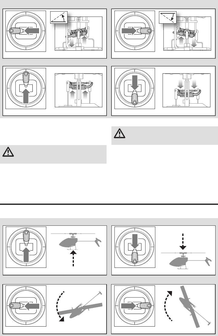
25 DE
Einführung in die Hauptsteuerfunktionen
Wenn Ihnen die Steuerung Ihres mCP S noch nicht geläufi g ist, nehmen Sie sich bitte ein paar Minuten Zeit, umsich mit
ihr vertraut zu machen, bevor Sie Ihren ersten Flug versuchen.
Motor
Stellen Sie den Hubschrauber draussen auf eine saubere und
gerade Fläche (Beton oder Asphalt) die frei von Hindernissen sein
muß. Halten Sie sich immer von drehenden Rotoblättern fern.
ACHTUNG: Halten Sie Tiere vom Hubschrauber weg.
Diese könnten sich verletzen wenn Sie den
Hubschrauber angreifen oder zu ihm laufen.
1. Beide Motoren piepen 3 mal wenn die Regler des
Hubschraubers armiert sind. Überprüfen Sie bitte bevor
Sie weitermachen, dass der Gassteuerknüppel in der
niedrigsten Position ist.
2. Schalten Sie die Gas aus Funktion aus.
WARNUNG: Halten Sie mindestens 10 Meter
Abstand zum Hubschrauber wenn der Motor läuft.
Versuchen Sie nicht den Hubschrauber jetzt schon zu fl iegen.
3. Versichern Sie sich dass das Gas vollständig nach unten
gestellt ist und das der Sender wie in der Sendereinstell-
tabelle beschrieben eingestellt ist. Geben Sie langsam Gas
bis sich die Blätter zu drehen beginnen. Die Hauptrotor-
blätter drehen von oben betrachtet im Uhrzeigersinn. Die
Heckrotorblätter drehen gegen den Uhrzeigersinn wenn der
Hubschrauber von der rechten Seite betrachtet wird.
Seitenansicht Seitenansicht
Querruder
Kollektive Pitch
Kollektive Pitch oben Kollektive Pitch unten
Querruder nach links Querruder nach rechts
Rückansicht Rückansicht
Sinken
Aufsteigen
Kollektive Pitch
Seitenansicht Seitenansicht
Kollektive Pitch oben Kollektive Pitch unten
Seitenruder
DraufsichtDraufsicht
Nase dreht nach links
Seitenruder nach links Seitenruder nach rechts Nase dreht nach rechts
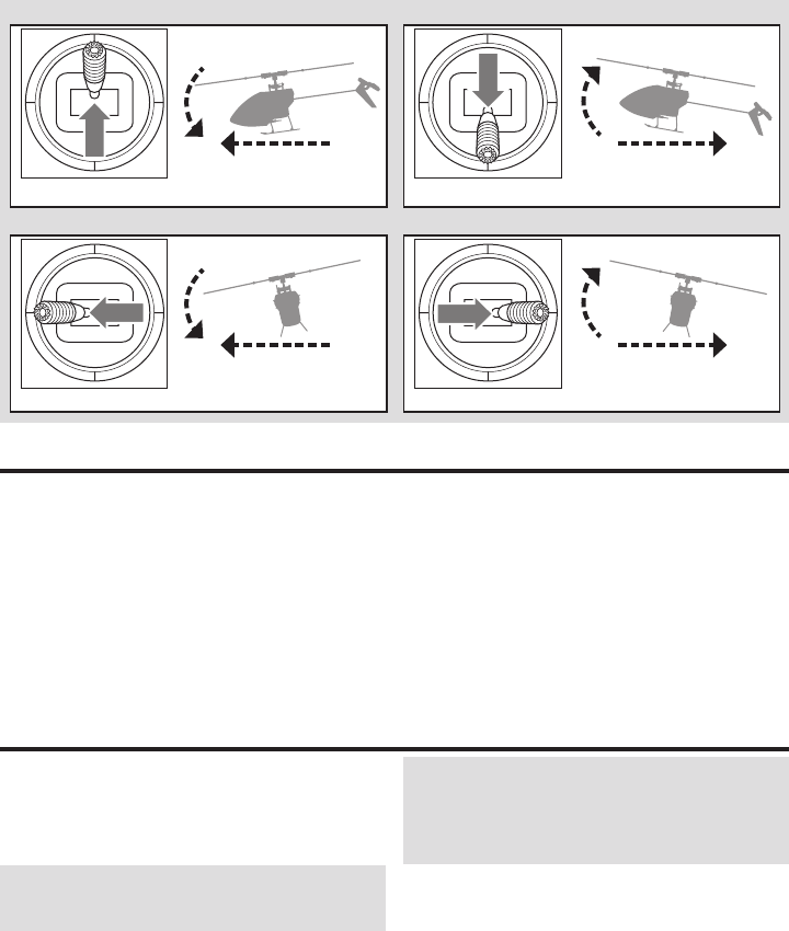
26
DE
Bei einem Gefühl der Panik beim Fliegen, den Bindungs-/Not-
schalter drücken und halten und die Steuerknüppel in die Neut-
ralposition bewegen. Die SAFE-Technologie bringt das Fluggerät
sofort in eine aufrechte Lage, sofern es genügend Höhe hat und
sich keine Hindernisse auf seinem Kurs befi nden.
HINWEIS: Die Notrückholung nicht aktivieren, wenn der
Hubschrauber nicht über eine ausreichende Höhe für ein
erfolgreiches Abfangen verfügt.
Den Kollektivsteuerhebel auf 50% zurückbringen und den
Notschalter loslassen, um die Notrückholung auszuschalten
und in den aktuellen Flug-Modus zurückzukehren.
HINWEIS: Vor dem Loslassen des Notschalters sicherstel-
len, dass der Kollektivsteuerhebel auf die Position 50%
zurückgebracht wurde. Sobald der Notschalter losgelassen
wurde, steht der komplette negative Kollektivsteuerhebel zur
Verfügung, wodurch der mCP S schnell absinken könnte.
• Die Notrückholung ist dafür gedacht, dem Piloten
Vertrauen zu geben, seine Flugfähigkeiten weiter zu
verbessern.
• Für das schnellste Abfangen den Kollektivsteuerhebel
auf 50% bringen und alle anderen Sendersteuerungen
auf neutral stellen.
• Sobald das Modell eine aufrechte Lage erreicht hat, wird
die negative Kollektivsteuerung reduziert, um zu verhin-
dern, dass der Pilot das Modell zum Absturz bringt.
Notrückholung
Im Stabilitätsmodus fl iegt der Hubschrauber ähnlich ei-
nem Hubschrauber mit fester Blattverstellung (die Schräg-
lage ist begrenzt). Wenn der Steuerknüppel losgelassen
wird, kehrt sich das Modell in den Horizontalfl ug zurück.
Im Fortgeschrittenenmodus ist die Schräglage nicht
begrenzt. Wenn der Steuerknüppel losgelassen wird, kehrt
sich das Modell nicht in den Horizontalfl ug zurück. Die
Kopfdrehzahl ist etwas geringer und die Steuerung verfügt
über ein „weicheres“ Gefühl. Dieser Modus ist großartig
geeignet für das Lernen des Vorwärtsfl ugs und einfacher
Flugmanöver wie Stall-Turns und Schleifen.
Im Agilitätsmodus ist die Schräglage nicht begrenzt. Wenn
der Steuerknüppel losgelassen wird, kehrt sich das Modell
nicht in den Horizontalfl ug zurück. Die Kopfdrehzahl ist
ebenfalls höher. Dieser Modus ist großartig geeignet für
3D-Kunstfl üge wie stationäre Flips und Tic-Tocs.
Beschreibung des Flugmodus
Vorwärts
Links
Rückwärts
Rechts
Höhenruder
Querruder
Seitenansicht
Rückansicht
Rückansicht
Seitenansicht
Höhenruder nach unten
Querruder nach links
Höhenruder nach oben
Querruder nach rechts

27 DE
Vor der Wahl des Standorts für das Fliegen des
Fluggeräts die örtlichen Gesetze und Verordnungen
konsultieren.
Ist dies Ihr erster Hubschrauber mit kollektiver Blattverstellung
empfehlen wir Ihnen, sich Hilfe von einem erfahrenen Hub-
schrauberpiloten oder Fliegerclub zu holen, bis Sie sich für einen
Alleinfl ug sicher fühlen.
Wir empfehlen das Fliegen des Fluggeräts im Freien bei Wind-
stille oder in einer großen Sporthalle. Das Fliegen in der Nähe
von Häusern, Bäumen, Kabeln und Gebäuden vermeiden. Das
Fliegen in Umgebungen mit vielen Menschen, wie belebte Parks,
Schulhöfe oder Fußballfelder, sollte ebenfalls vermieden werden.
Es sollte am besten von einer glatten, fl achen Oberfl äche aus
gefl ogen werden, da dadurch das Modell gleiten kann, ohne
umzukippen. Den Hubschrauber etwa 60cm (2 Fuß) über
dem Boden halten. Das Heck während der ersten Flüge auf
sich gerichtet lassen, um die Steuerausrichtung einheitlich zu
halten. Die Freigabe des Steuerknüppels im Stabilitätsmodus
ermöglicht das selbstständige Ausrichten des Hubschraubers.
Durch die Aktivierung des Notrückholungs-Schalters wird der
Hubschrauber schnell in den Horizontalfl ug übergehen. Bei Ori-
entierungslosigkeit im Stabilitätsmodus den Gashebel langsam
senken, um sanft zu landen.
Während der ersten Flüge nur starten, landen und über einem
Punkt schweben.
Start
WICHTIG: Falls der Hauptmotor oder der Heckmotor
nicht ordnungsgemäß starten, wenn die Gaszufuhr zum
ersten Mal angelegt wird, den Gashebel sofort auf Leer-
lauf bringen und erneut versuchen. Bleibt das Problem
bestehen, den Flug-Akku trennen, den Getriebezug auf
Verklemmungen prüfen und sicherstellen, dass sich
keine Kabel um die Getriebe gewickelt haben.
Das Modell auf eine fl ache, ebene Oberfl äche ohne
Hindernisse stellen und sich 10Meter (30Fuß) vom
Fluggerät entfernen. Die Gaszufuhr langsam erhöhen, bis
das Modell etwa 60cm (2 Fuß) über dem Boden schwebt,
und die Trimmungen prüfen, sodass das Modell wie
gewünscht fl iegt. Sobald die Trimmungen angepasst sind,
kann das Modell gefl ogen werden.
Schweben
Beim Vornehmen kleiner Korrekturen am Sender den
Hubschrauber über einem Punkt halten. Bei Flügen in Wind-
stille sollte das Modell fast keine korrigierenden Eingaben
erfordern. Nach dem Bewegen des Steuerhebels und dessen
Rückkehr in die Mittelposition sollte sich das Modell von sel-
ber ausrichten. Das Modell kann sich aufgrund von Trägheit
weiterhin bewegen. Den Steuerhebel in die entgegengesetzte
Richtung bewegen, um die Bewegung zu stoppen.
Nachdem Sie sich an den Schwebefl ug gewöhnt haben,
können Sie mit dem Fliegen zu anderen Punkten fortfahren,
wobei das Heck immer auf Sie gerichtet ist. Sie können
mit dem Gashebel ebenfalls auf- und absteigen. Wenn Sie
sich an diese Flugmanöver gewöhnt haben, können Sie das
Fliegen mit dem Heck in verschiedenen Ausrichtungen ver-
suchen. Es ist wichtig, daran zu denken, dass die Eingaben
der Flugsteuerung mit dem Hubschrauber mitdrehen. Versu-
chen Sie sich, die Steuereingaben in Bezug auf die Nase des
Hubschraubers vorzustellen. Zum Beispiel wird „Vorwärts“
immer die Nase des Hubschraubers senken.
Die durchschnittliche Flugzeit des Hubschraubers mit dem
empfohlenen Akku beträgt etwa 4Minuten, abhängig davon,
wie aggressiv das Fluggerät gefl ogen wird.
Niedrigtrennspannung (LVC)
Die Niedrigtrennspannung verringert die Stromzufuhr zu den
Motoren, wenn die Akkuspannung sinkt. Wenn die Motorleis-
tung sinkt und die LED auf dem Geschwindigkeitsregler blinkt,
das Fluggerät sofort landen und den Flug-Akku aufl aden.
Die LVC verhindert nicht das übermäßige Entladen des Akkus
während der Lagerung.
HINWEIS: Das wiederholte Fliegen bei Niedrigtrennspannung
kann zu Schäden am Akku führen.
Landen
Zum Laden die Gaszufuhr bei einem niedrigen Schwebefl ug
langsam verringern. Nach der Landung den LiPo-Akku vom
Fluggerät trennen und entfernen, um eine Teilentladung
zu vermeiden. Den Flug-Akku vor dem Lagern vollständig
aufl aden. Beim Lagern darauf achten, dass die Akkuladung
nicht unter 3 V pro Zelle fällt.
Kontrollen nach dem Flug und Wartung
Fliegen des mCP S
Kugelköpfe- u.
Pfannen
Stellen Sie bitte sicher, dass die Pfanne den Kugelkopf hält ihn aber nicht blockiert. Ist der Kugelkopf zu
lose, kann er sich während des Fluges lösen und einen Absturz verursachen. Ersetzen Sie verschlissene
Kugelköpfe und Pfannen bevor sie versagen.
Reinigung Vergewissern Sie sich vor der Reinigung, dass der Akku nicht angeschlossen ist. Entfernen Sie Staub und
Schmutzrückstände mit einer weichen Bürste oder einem trockenen fusselfreien Tuch.
Lager Ersetzen Sie Lager die nicht mehr frei drehen.
Verkabelung Stellen Sie sicher, dass die Verkabelung keine beweglichen Teile blockiert. Ersetzen Sie beschädigte Verkabe-
lung und lose Stecker.
Befestigungs-
elemente
Stellen Sie sicher, dass keine Schrauben, andere Befestigungselemente oder Stecker lose sind. Ziehen Sie
Metallschrauben in Kunststoffteilen nicht zu stark an. Ziehen Sie Schrauben so an, dass die Teile zusam-
mengefügt sind, und drehen Sie die Schrauben danach um eine 1/8-Umdrehung.

28
DE
Leitfaden zur Problemlösung
Problem Mögliche Ursache Lösung
Die Reaktion der Hub-
schraubersteuerung ist
ungleichmäßig oder erfor-
dert zusätzliche Trimmung,
um eine Bewegung zu
neutralisieren
Fluggerät war nicht ordnungsge-
mäß initialisiert oder eine Vibration
beeinträchtigt den Sensorbetrieb
Den Flug-Akku trennen, die Steuertrimmung zentrieren
und den Hubschrauber erneut initialisieren
Hubschrauber reagiert
nicht auf Gas
Gas zu hoch und/oder Gastrim-
mung zu hoch
Den Flug-Akku trennen, den Gashebel in die niedrigste Positi-
on bringen und die Gastrimmung ein paar Klicks senken. Den
Flug-Akku anschließen und das Modell initialisieren lassen
Hubschrauber bewegt sich während
der Initialisierung
Den Flug-Akku trennen und den Hubschrauber erneut
initialisieren, während eine Bewegung des Hubschraubers
unterbunden wird
Hubschrauber weist eine
verringerte Flugzeit auf
oder ist untermotorisiert
Ladezustand des Akkus ist niedrig Den Flug-Akku komplett aufl aden
Der Flug-Akku ist beschädigt
Den Flug-Akku ersetzen und die Anweisungen zum Flug-
Akku befolgen
Flugbedingungen können zu kalt sein Sicherstellen, dass der Akku vor der Verwendung warm
(Raumtemperatur) ist
LED auf der Flugsteuerung
blinkt schnell und Flug-
gerät reagiert nicht auf
den Sender (während des
Bindens)
Sender während des Bindungsvor-
gangs zu nah am Fluggerät
Den Sender ausschalten. Den Sender in eine größere
Entfernung zum Fluggerät bringen. Den Flug-Akku vom
Fluggerät trennen und wieder anschließen. Die Anweisun-
gen zum Binden befolgen
Bindungsschalter wurde nicht
gehalten, während Sender einge-
schalten wurde Sender ausschalten und den Bindungsvorgang wiederholen
Fluggerät oder Sender zu nah an einem
großen Metallobjekt, einer drahtlosen
Quelle oder einem anderen Sender
Fluggerät und Sender an einen
anderen Standort bringen und Binden erneut versuchen
LED auf der Flugsteuerung
blinkt schnell und Hub-
schrauber reagiert nicht
auf den Sender (nach dem
Binden)
Weniger als 5Sekunden zwischen
dem ersten Einschalten am Sender
und Verbinden des Flug-Akkus am
Hubschrauber gewartet
Den Sender eingeschaltet belassen. Den Flug-Akku vom
Hubschrauber trennen und wieder anschließen
Der Hubschrauber ist an einen
anderen Modellspeicher gebunden
(nur ModelMatch-Sender)
Den korrekten Modellspeicher auf dem Sender wählen.
Den Flug-Akku vom Hubschrauber trennen und wieder
anschließen
Ladezustand des Flug-Akkus oder
des Sender-Akkus zu niedrig Akkus ersetzen oder aufl aden
Fluggerät oder Sender zu nah an einem
großen Metallobjekt, einer drahtlosen
Quelle oder einem anderen Sender
Fluggerät und Sender an einen anderen Standort bringen
und Verbinden erneut versuchen
Hubschrauber vibriert oder
wackelt während des Flugs Beschädigte Rotorblätter, Spindel
oder Blatthalter
Hauptrotorblätter und Blatthalter auf Risse oder Splitter
überprüfen. Beschädigte Bauteile ersetzen. Verbogene
Spindel ersetzen
Willkürliche Bewegungen
im Flug Vibrationen
Bestätigen, dass Empfänger ordnungsgemäß am Hubschrau-
ber angebracht ist. Alle rotierenden Bauteile überprüfen und
ausbalancieren. Bestätigen, dass Hauptwelle und Heckrotor
nicht beschädigt oder verbogen sind. Mechanik auf beschä-
digte Bauteile überprüfen und bei Bedarf ersetzen
Rotorblätter
Stellen Sie sicher dass die Rotorblätter und andere Teile die mit hoher Geschwindigkeit drehen keine
Beschädigungen aufweisen wie: Brüche, Risse, Abplatzer oder Kratzer. Ersetzen Sie beschädigte Teile vor dem
fl iegen. Überprüfen Sie ob beide Rotorblätter gleich korrekt befestigt sind. Wird der Hubschrauber seitlich
gehalten sollten sich beide Rotorblätter im Gewicht ausgleichen. Beginnt der Hubschrauber sich etwas zu
schütteln könnten sich die Rotorblätter lösen.
Heckrotor Überprüfen Sie den Hecktrotor und Heckausleger auf Beschädigungen und ersetzen die Teile wenn notwendig.
Mechanik Überprüfen Sie den Rahmen und Fahrwerk und ersetzen Teile wenn notwendig. Überprüfen Sie die Hauptro-
torwelle. Überprüfen Sie das Zahnfl ankenspiel und ob sich die Mechanik ohne Beeinträchtigung um 360°
drehen kann. Überprüfen Sie alle Kabel und Verbinder und ersetzen diese falls notwendig.
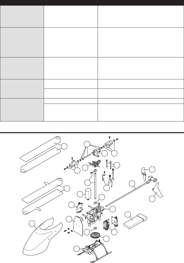
29 DE
8
9
1
11
10
13
12
12
5
7
19
16
20
18
3
18
17
2
4
17
14
15
6
19
Explosionszeichnung
Problem Mögliche Ursache Lösung
Heckschwingungen/
Schlingern oder schlechte
Leistung
Beschädigter Heckrotor, Heckaus-
leger, Hauptgetriebeeingriff, Haupt-
welle, lose Schrauben, Vibration
Den Heckrotor auf Schäden untersuchen. Den Heckausle-
ger und die Hauptwelle auf Risse untersuchen. Den Haupt-
getriebeeingriff überprüfen und durch volle Drehung sicher-
stellen, dass es keine engen Stellen im Zahneingriff gibt.
Beschädigte oder verschlissene Komponenten ersetzen
Drift bei Windstille Vibration, beschädigtes Gestänge,
beschädigter Servo
Im Normalbetrieb sollten die Sendertrimmungen keine
Anpassungen erfordern und die Mittelpositionen werden
während der Initialisierung gespeichert. Sind Anpassungen
an der Trimmung nach dem Start notwendig, das Gleich-
gewicht aller rotierenden Komponenten überprüfen, sicher-
stellen, dass die Gestänge nicht beschädigt sind und sich
die Servos im richtigen betriebsbereiten Zustand befi nden
Driften im Wind Normal
Das Modell wird mit dem Wind driften, sollte ab.er im Flug
horizontal bleiben. Den Steuerknüppel in der notwendigen
Position halten, um das Modell stationär zu halten. Das Modell
muss sich in den Wind lehnen, um stationär zu bleiben. Falls
das Modell horizontal bleibt, dann wird es mit dem Wind driften
Notrückholung oder Rück-
kehr in den Horizontalfl ug
wird das Modell nicht
ausrichten
Das Modell wurde nicht auf einer ge-
raden, ruhigen Oberfl äche initialisiert Das Modell auf einer geraden und ruhigen Oberfl äche
erneut initialisieren
Das Modell wurde nicht von einer
geraden Oberfl äche genommen Immer von einer geraden Oberfl äche heben
Schwere Vibrationen
Hauptwelle ist rissig Die Hauptwelle auf Risse überprüfen und bei Bedarf ersetzen
Rotierende Komponenten nicht im
Gleichgewicht
Hauptwelle, Heckrotor, Hauptrotorblätter, Hauptrahmen und Ad-
apter auf Schäden untersuchen, bei Bedarf ersetzen. Vibrationen
müssen für Notrückholung minimiert werden und auf Horizontal-
fl ugfunktionen zurückkehren, um ordnungsgemäß zu funktionieren

30
DE
Teile-Nr. Description
1 BLH3503 Hauptmotor mit Ritzel
2 BLH3504 Gleitkufe und Akku-Halterung
3 BLH3505 Hauptrahmen mit Hardware
4 BLH3506 Hauptgetriebe
5 BLH3507 Hauptwelle mit Manschette und Hardware
6 BLH3508 Schubstangensatz mit Gelenkkopf: 3Stk
7 BLH3509 Komplette Präzisions-Taumelscheibe
8 BLH3510 Hochleistungs-Hauptrotorblätter mit
Hardware
9 BLH3511 Schnellfl ug-Hauptrotorblätter mit Hardware
10 BLH3512 Hauptrotornabe mit Hardware
11 BLH3513 Spindel für periodische Blattverstellung
mit O-Ring, Buchse und Hardware
Teile-Nr. Description
12 BLH3514 Hauptrotorblatthalter mit Lager
13 BLH3522 Rotorkopf-Verbindungssatz (8)
14 BLH3602 Heckausleger-Baugruppe
15 BLH3603 Heckrotor
16 BLH5101 3-In-1 Flybareless-Steuereinheit
17 BLH5103 Rote Haube mit vertikalem Seitenleitwerk
18 EFLH2215 Äußeres Wellenlager 3x6x2mm (2)
19
SPMSH2025L
2,0 Gramm linear angeordneter
Leistungsservo, 15mm Kabel
20
EFLB2101S40
210mA 1S 3,7V 40C LiPo-Akku
EFLC1013
1S USB LiPo Ladegerät, 500mA
EFLRMLP6 MLP6DSM 6-KANAL SAFE Tx (nur RTF)
Teile-Nr. Description
BLH3519 Komplette Haube mit vertikalem Seitenleitwerk
BLH3602L Lange Heckausleger-Baugruppe
BLH3603GR Grüner Heckrotor (1)
BLH3603OR Oranger Heckrotor (1)
BLH3603YE Gelber Heckrotor (1)
EFLA7002UM 1S Hochstrom UM Akku-Adapterleitung
EFLB2001S30 200mA 1S 3,7V 30C LiPo-Akku
EFLC1004 Celctra 4-Anschluss 1C 3,7V 0,3
Wechselstrom-/Gleichstrom LiPo-Ladegerät
Teile-Nr. Description
EFLH3023 Kohlefaser Training-Getriebesatz
SPM20000 DX20 20-Kanal-System mit AR9020 M2
SPM6650 DX6e 6-Kanal-System mit AR610 RX
SPM6750 DX6 System MD2
SPMR1000 Nur DXe-Sender
SPMR8000 Nur DX8-Sender MD2
SPMR9910 Nur schwarzer DX9-Sender MD2
Warnung
Ein ferngesteuertes Modell ist kein Spielzeug. Es kann, wenn es
falsch eingesetzt wird, zu erheblichen Verletzungen bei Lebewesen
und Beschädigungen an Sachgütern führen. Betreiben Sie Ihr
RC-Modell nur auf freien Plätzen und beachten Sie alle Hinweise
der Bedienungsanleitung des Modells wie auch der Fernsteuerung.
Garantiezeitraum
Exklusive Garantie Horizon Hobby LLC (Horizon) garantiert, dass
dasgekaufte Produkt frei von Material- und Montagefehlern ist.
Der Garantiezeitraum entspricht den gesetzlichen Bestimmung
des Landes, in dem das Produkt erworben wurde. In
Deutschland beträgt der Garantiezeitraum 6 Monate und der
Gewährleistungszeitraum 18 Monate nach dem Garantiezeitraum.
Einschränkungen der Garantie
(a) Die Garantie wird nur dem Erstkäufer (Käufer) gewährt und
kann nicht übertragen werden. Der Anspruch des Käufers
besteht in der Reparatur oder dem Tausch im Rahmen die-
ser Garantie. Die Garantie erstreckt sich ausschließlich auf
Produkte, die bei einem autorisierten Horizon Händler erwor-
ben wurden. Verkäufe an dritte werden von dieser Garantie
nicht gedeckt. Garantieansprüche werden nur angenommen,
wenn ein gültiger Kaufnachweis erbracht wird. Horizon behält
sich das Recht vor, diese Garantiebestimmungen ohne
Ankündigung zu ändern oder modifizieren und widerruft dann
bestehende Garantiebestimmungen.
(b) Horizon übernimmt keine Garantie für die Verkaufbarkeit des
Produktes, die Fähigkeiten und die Fitness des Verbrauchers
für einen bestimmten Einsatzzweck des Produktes. Der Käufer
allein ist dafür verantwortlich, zu prüfen, ob das Produkt
seinen Fähigkeiten und dem vorgesehenen Einsatzzweck
entspricht.
(c) Ansprüche des Käufers ¬ Es liegt ausschließlich im Ermessen
von Horizon, ob das Produkt, bei dem ein Garantiefall fest-
gestellt wurde, repariert oder ausgetauscht wird. Dies sind
die exklusiven Ansprüche des Käufers, wenn ein Defekt
festgestellt wird.
Horizon behält sich vor, alle eingesetzten Komponenten zu
prüfen, die in den Garantiefall einbezogen werden können. Die
Entscheidung zur Reparatur oder zum Austausch liegt nur bei
Horizon. Die Garantie schließt kosmetische Defekte oder Defekte,
hervorgerufen durch höhere Gewalt, falsche Behandlung des
Produktes, falscher Einsatz des Produktes, kommerziellen Einsatz
oder Modifikationen irgendwelcher Art aus.
Die Garantie schließt Schäden, die durch falschen Einbau, falsche
Handhabung, Unfälle, Betrieb, Service oder Reparaturversuche, die
nicht von Horizon ausgeführt wurden aus.
Ausgeschlossen sind auch Fälle die bedingt durch (vii) eine
Nutzung sind, die gegen geltendes Recht, Gesetze oder Regularien
verstoßen haben. Rücksendungen durch den Käufer direkt
an Horizon oder eine seiner Landesvertretung bedürfen der
Schriftform.
Garantie und Service Informationen
Teileliste
Optionsteile
31 DE
Garantie und Service Kontaktinformationen
Rechtliche Informationen für die Europäische Union
Anweisungen zur Entsorgung von Elektro-und Elektronik-Altgeräten für Benutzer in der Europäischen Union
Dieses Produkt darf nicht zusammen mit anderem Abfall entsorgt werden. Stattdessen ist der Benutzer dafür
verantwortlich, unbrauchbare Geräte durch Abgabe bei einer speziellen Sammelstelle für das Recycling von
unbrauchbaren elektrischen und elektronischen Geräten zu entsorgen. Die separate Sammlung und das Re-
cycling von unbrauchbaren Geräten zum Zeitpunkt der Entsorgung hilft, natürliche Ressourcen zu bewahren
und sicherzustellen, dass Geräte auf eine Weise wiederverwertet werden, bei der die menschliche Gesundheit
und die Umwelt geschützt werden. Weitere Informationen dazu, wo Sie unbrauchbare Geräte zum Recycling
abgeben können, erhalten Sie bei lokalen Ämtern, bei der Müllabfuhr für Haushaltsmüll sowie dort, wo Siedas
Produkt gekauft haben.
EU Konformitätserklärung
Horizon LLC erklärt hiermit, dass dieses Produkt konform zu den essentiellen Anforderungen
der RED und EMC Direktive ist.
Eine Kopie der Konformitätserklärung ist online unter folgender Adresse verfügbar :
http://www.horizonhobby.com/content/support-render-compliance.
Land des Kauf Horizon Hobby Telefon/E-mail Adresse Adresse
Europäische Union Horizon Technischer Service service@horizonhobby.eu Hanskampring 9
D 22885 Barsbüttel, Germany
Sales: Horizon Hobby GmbH +49 (0) 4121 2655 100
Schadensbeschränkung
Horizon ist nicht für direkte oder indirekte Folgeschäden,
Einkommensausfälle oder kommerzielle Verluste, die in irgendeinem
Zusammenhang mit dem Produkt stehen verantwortlich, unabhän-
gig ab ein Anspruch im Zusammenhang mit einem Vertrag, der
Garantie oder der Gewährleistung erhoben werden. Horizon wird
darüber hinaus keine Ansprüche aus einem Garantiefall akzeptie-
ren, die über den individuellen Wert des Produktes hinaus gehen.
Horizon hat keinen Einfluss auf den Einbau, die Verwendung oder
die Wartung des Produktes oder etwaiger Produktkombinationen,
die vom Käufer gewählt werden. Horizon übernimmt keine Garantie
und akzeptiert keine Ansprüche für in der folge auftretende
Verletzungen oder Beschädigungen. Mit der Verwendung und
dem Einbau des Produktes akzeptiert der Käufer alle aufgeführten
Garantiebestimmungen ohne Einschränkungen und Vorbehalte.
Wenn Sie als Käufer nicht bereit sind, diese Bestimmungen im
Zusammenhang mit der Benutzung des Produktes zu akzeptieren,
werden Sie gebeten, dass Produkt in unbenutztem Zustand in der
Originalverpackung vollständig bei dem Verkäufer zurückzugeben.
Sicherheitshinweise
Dieses ist ein hochwertiges Hobby Produkt und kein Spielzeug.
Es muss mit Vorsicht und Umsicht eingesetzt werden und
erfordert einige mechanische wie auch mentale Fähigkeiten. Ein
Versagen, das Produkt sicher und umsichtig zu betreiben kann zu
Verletzungen von Lebewesen und Sachbeschädigungen erhebli-
chen Ausmaßes führen. Dieses Produkt ist nicht für den Gebrauch
durch Kinder ohne die Aufsicht eines Erziehungsberechtigten vor-
gesehen. Die Anleitung enthält Sicherheitshinweise und Vorschriften
sowie Hinweise für die Wartung und den Betrieb des Produktes. Es
ist unabdingbar, diese Hinweise vor der ersten Inbetriebnahme zu
lesen und zu verstehen. Nur so kann der falsche Umgang verhin-
dert und Unfälle mit Verletzungen und Beschädigungen vermieden
werden.
Fragen, Hilfe und Reparaturen
Ihr lokaler Fachhändler und die Verkaufstelle können eine
Garantiebeurteilung ohne Rücksprache mit Horizon nicht durchfüh-
ren. Dies gilt auch für Garantiereparaturen. Deshalb kontaktieren
Sie in einem solchen Fall den Händler, der sich mit Horizon kurz
schließen wird, um eine sachgerechte Entscheidung zu fällen, die
Ihnen schnellst möglich hilft.
Wartung und Reparatur
Muss Ihr Produkt gewartet oder repariert werden, wenden Sie sich
entweder an Ihren Fachhändler oder direkt an Horizon.
Rücksendungen / Reparaturen werden nur mit einer von Horizon
vergebenen RMA Nummer bearbeitet. Diese Nummer erhalten Sie
oder ihr Fachhändler vom technischen Service. Mehr Informationen
dazu erhalten Sie im Serviceportal unter www. Horizonhobby.de
oder telefonisch bei dem technischen Service von Horizon.
Packen Sie das Produkt sorgfältig ein. Beachten Sie, dass der
Originalkarton in der Regel nicht ausreicht, um beim Versand nicht
beschädigt zu werden. Verwenden Sie einen Paketdienstleister
mit einer Tracking Funktion und Versicherung, da Horizon bis zur
Annahme keine Verantwortung für den Versand des Produktes
übernimmt. Bitte legen Sie dem Produkt einen Kaufbeleg bei,
sowie eine ausführliche Fehlerbeschreibung und eine Liste aller
eingesendeten Einzelkomponenten. Weiterhin benötigen wir die
vollständige Adresse, eine Telefonnummer für Rückfragen, sowie
eine Email Adresse.
Garantie und Reparaturen
Garantieanfragen werden nur bearbeitet, wenn ein
Originalkaufbeleg von einem autorisierten Fachhändler beiliegt,
aus dem der Käufer und das Kaufdatum hervorgeht. Sollte sich
ein Garantiefall bestätigen wird das Produkt repariert oder ersetzt.
Diese Entscheidung obliegt einzig Horizon Hobby.
Kostenpflichtige Reparaturen
Liegt eine kostenpflichtige Reparatur vor, erstellen wir einen
Kostenvoranschlag, den wir Ihrem Händler übermitteln. Die
Reparatur wird erst vorgenommen, wenn wir die Freigabe des
Händlers erhalten. Der Preis für die Reparatur ist bei Ihrem
Händler zu entrichten. Bei kostenpflichtigen Reparaturen werden
mindestens 30 Minuten Werkstattzeit und die Rückversandkosten
in Rechnung gestellt. Sollten wir nach 90 Tagen keine
Einverständniserklärung zur Reparatur vorliegen haben, behalten
wir uns vor, das Produkt zu vernichten oder anderweitig zu ver-
werten.
ACHTUNG: Kostenpflichtige Reparaturen nehmen wir nur
für Elektronik und Motoren vor. Mechanische Reparaturen,
besonders bei Hubschraubern und RC-Cars sind extrem
aufwendig und müssen deshalb vom Käufer selbst vorge-
nommen werden. 10/15

32
FR
AVERTISSEMENT: Lisez la TOTALITE du manuel d’utilisation afi n de vous familiariser avec les caractéristiques
du produit avant de le faire fonctionner. Une utilisation incorrecte du produit peut entraîner l’endommagement
du produit lui-même, ainsi que des risques de dégâts matériels, voire de blessures graves.
Ceci est un produit de loisirs perfectionné. Il doit être manipulé avec prudence et bon sens et requiert quelques apti-
tudes de base en mécanique. Toute utilisation de ce produit ne respectant pas les principes de sécurité et de respon-
sabilité peut entraîner des dégâts matériels, endommager le produit et provoquer des blessures. Ce produit n’est pas
destiné à être utilisé par des enfants sans la surveillance directe d’un adulte. N’essayez pas de démonter le produit, de
l’utiliser avec des composants incompatibles ou d’en améliorer les performances sans l’accord d’Horizon Hobby, LLC.
Ce manuel comporte des instructions relatives à la sécurité, au fonctionnement et à l’entretien. Il est capital de lire et
de respecter toutes les instructions et avertissements du manuel avant l’assemblage, le réglage ou l’utilisation afi n de
le manipuler correctement et d’éviter les dommages ou les blessures graves.
• Gardez une bonne distance de sécurité tout autour de
votre modèle, afi n d’éviter les collisions ou les blessures.
Ce modèle est contrôlé par un signal radio, qui peut être
soumis à des interférences provenant de nombreuses
sources hors de votre contrôle. Une interférence peut
provoquer une perte momentanée de contrôle.
• Faites toujours fonctionner votre modèle dans une zone
dégagée, à l’écart de voitures, du trafi c et des personnes.
• Respectez toujours scrupuleusement les instructions
et les mises en garde concernant ce produit et tous les
équipements optionnels/complémentaires (chargeurs,
batteries rechargeables, etc.) que vous utilisez.
• Tenez tous les produits chimiques, les petites pièces et
les composants électroniques hors de portée des enfants.
• Évitez toujours d’exposer à l’eau tout équipement non
spécifi quement conçu et protégé à cet effet. L’humidité
endommage les composants électroniques.
• Ne léchez et ne mettez jamais en bouche quelque partie
de votre modèle que ce soit - risque de blessures graves
voire danger de mort.
• Ne faites jamais fonctionner votre modèle lorsque les
batteries de l’émetteur sont faibles.
• Gardez toujours le modèle à vue et gardez-en toujours le
contrôle.
• Baissez toujours le manche des gaz lorsque les pales
touchent un objet ou le sol.
• Utilisez toujours des batteries complètement chargées.
• Gardez toujours l’émetteur sous tension lorsque le
modèle est en marche.
• Enlevez toujours les batteries avant le démontage.
• Veillez toujours à ce que les pièces en mouvement soient
propres.
• Veillez toujours à ce que toutes les pièces soient sèches.
• Laissez toujours le temps aux pièces de refroidir avant de
les toucher.
• Enlevez toujours les batteries après utilisation.
• Ne faites jamais voler un modèle dont le câblage est
endommagé.
• Ne touchez jamais des pièces en mouvement.
REMARQUE
Signifi cation de certains termes spécifi ques
La totalité des instructions, garanties et autres documents est sujette à modifi cation à la seule discrétion d’Horizon
Hobby, LLC. Pour obtenir la documentation à jour, rendez-vous sur le site horizonhobby.com et cliquez sur l’onglet de
support de ce produit.
Les termes suivants sont utilisés dans l’ensemble du manuel pour indiquer différents niveaux de danger lors de
l’utilisation de ce produit:
AVERTISSEMENT: Procédures qui, si elles ne sont pas suivies correctement, peuvent entraîner des dégâts matériels,
des dommages collatéraux et des blessures graves OU engendrer une probabilité élevée de blessure superfi cielle.
ATTENTION: Procédures qui, si elles ne sont pas suivies correctement, peuvent entraîner des dégâts matériels ET des
blessures graves.
REMARQUE: Procédures qui, si elles ne sont pas suivies correctement, peuvent entraîner des dégâts matériels ET
potentiellement un risque faible de blessures.
Précautions et avertissements liés à la sécurité
14 ans et plus. Ceci n'est pas un jouet.

33 FR
• Hélicoptère Blade mCP S
• Batteries au Li-Po 2 210mAh 1S 3,7V 40C
• Chargeur Li-Po USB 1S (prêt-à-voler uniquement)
• Émetteur MLP6DSM (prêt-à-voler uniquement)
• 4 piles AA (prêt-à-voler uniquement)
Contenu de la boîte ......................................................... 33
Préparation au premier vol .............................................. 34
Procédure de vol ............................................................. 34
Avertissements relatifs à la charge ................................. 34
Charge de la batterie ...................................................... 34
Installation des piles de l'émetteur (RTF) ......................... 35
Commandes de l'émetteur (RTF) ..................................... 35
Paramétrage de l’émetteur (BNF) .................................... 36
Installation de la batterie ................................................. 38
Affectation de l’émetteur au récepteur ............................ 38
Coupure des gaz ............................................................. 39
Mode Acrobatique ........................................................... 39
Test des commandes ...................................................... 39
Compréhension des commandes de vol de base ............. 40
Description des modes de vol ......................................... 41
Récupération de panique ................................................ 42
Pilotage du mCP S .......................................................... 42
Liste de la maintenance
et des éléments à inspecter après vol .................................. 43
Guide de dépannage ....................................................... 43
Vue éclatée ..................................................................... 45
Liste des pièces détachées ............................................. 45
Pièces optionnelles ......................................................... 45
Garantie et réparations ................................................... 46
Coordonnées de garantie et réparations .......................... 47
Informations IC ............................................................... 47
Informations de conformité pour l’Union européenne ...... 47
Contenu de la boîte
Table des matières
Pour recevoir les mises à jour produit, les offres spéciales et plus encore, enregistrez votre produit sur www.bladehelis.com.
Longueur 240mm
Hauteur 90 mm
Diamètre du rotor principal 240mm
Diamètre du rotor d'anticouple 40mm
Masse 49 g
Caractéristiques
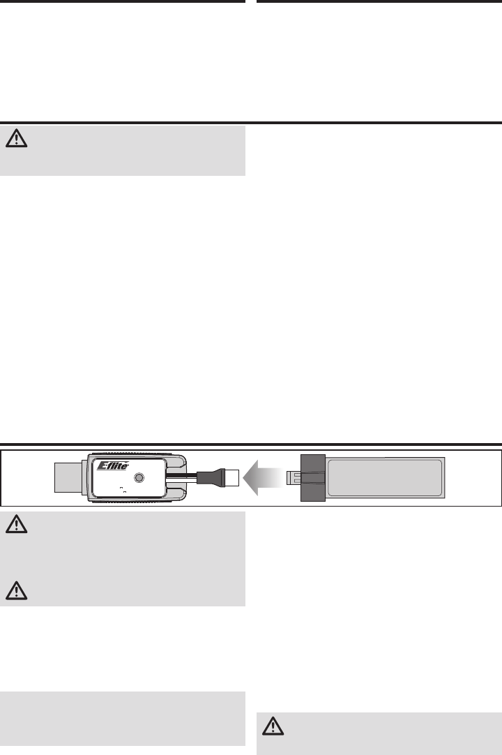
34
FR
ATTENTION: Toutes les instructions et les précautions
doivent être suivies. Une erreur de manipulation d’une
batterie Li-Po peut causer un incendie entraînant des dégâts
matériels avec risques de blessures.
• NE LAISSEZ JAMAIS DES BATTERIES EN CHARGE SANS
SURVEILLANCE.
• NE CHARGEZ JAMAIS DES BATTERIES DURANT LA NUIT.
• En manipulant, en chargeant ou en utilisant la batterie Li-Po
incluse, vous assumez tous les risques associés aux batter-
ies au lithium.
• Si la batterie commence à gonfl er ou à se dilater, cessez
immédiatement de l’utiliser. Si vous procédez à sa charge ou
à sa décharge, arrêtez immédiatement et déconnectez-la.
Continuer à utiliser, charger ou décharger une batterie qui
gonfl e ou se dilate peut provoquer un incendie.
• Pour obtenir de meilleurs résultats, entreposez toujours la
batterie à température ambiante dans un endroit sec.
• Lorsque vous transportez la batterie ou que vous la stockez
temporairement, la température doit toujours être comprise
entre 5 et 49°C.
• Ne stockez en aucun cas la batterie ou le modèle dans une
voiture ou à un endroit directement exposé à la lumière du
soleil. Laissée dans une voiture chaude, la batterie peut se
détériorer ou même prendre feu.
• Chargez toujours les batteries à l’écart de tout matériau
infl ammable.
• Contrôlez toujours l’état de la batterie avant la charge.
• Déconnectez toujours la batterie quand la charge est termi-
née et laissez le chargeur refroidir entre deux charges.
• Surveillez toujours la température de la batterie durant la charge.
• UTILISEZ UNIQUEMENT UN CHARGEUR CONÇU POUR
CHARGER LES BATTERIES LI-PO. L’utilisation d’un autre type
de chargeur risque de causer un incendie provoquant des
blessures corporelles et des dégâts matériels.
• Ne déchargez jamais une batterie Li-Po en dessous de 3V
par élément.
• Ne couvrez jamais les étiquettes d’avertissement avec des
bandes auto-agrippantes.
• Ne chargez jamais les batteries en dehors de la plage de
températures garantissant la sécurité.
• Ne chargez jamais des batteries endommagées.
• Ne tentez jamais de démonter ou modifi er le chargeur.
• Ne laissez jamais un mineur manipuler seul les batteries.
• Ne chargez jamais les batteries dans des lieux où les
températures sont extrêmes (température recommandée
entre 5 et 49°) ou en plein soleil.
Avertissements relatifs à la charge
Charge de la batterie
USB Li-Po
Charger
EFLC1013
SOLID RED LED
–Charging
DC Input:5.0V 500mA
DC Output:4.2V 500mA
LED OFF
–Charge
Complete
ATTENTION : Utilisez uniquement des chargeurs
spécifi quement conçus pour charger la batterie Li-Po
incluse. Le fait de charger la batterie avec un chargeur
non-compatible peut être à l’origine d’un incendie provoquant
des blessures corporelles ou des dégâts matériels.
ATTENTION : Ne dépassez jamais l'intensité de
charge recommandée.
Le chargeur de batterie (EFLC1013) inclus avec votre l'hélicop-
tère est conçu pour charger en toute sécurité la batterie Li-Po 1S
3.7V 210mA 40C incluse. Référez-vous aux précautions relatives
à la charge. Il est recommandé d'effectuer la charge durant l'ins-
pection du modèle. La batterie sera nécessaire pour effectuer les
étapes de vérifi cation du bon fonctionnement du modèle.
REMARQUE: Chargez uniquement des batteries froides
au toucher et non endommagées. Contrôlez l'état de la
batterie pour être sûr qu'elle n'est pas endommagée,
gonfl ée, pliée ou percée.
1. Insérez le chargeur dans un port USB.
Le chargeur utilise uniquement le courant fourni par le port
USB, il ne s'agit pas d'une liaison avec votre ordinateur. Les
alimentations USB, comme celles utilisées pour la charge
des téléphones portables peuvent être utilisées.
2. Connectez la batterie au chargeur comme indiqué sur
l'illustration au-dessus. Quand la connexion est réussie,
la DEL rouge du chargeur s'éclaire fi xement, indiquant
que la charge a débuté. Il faudra 30 minutes pour
charger entièrement une batterie 210mA déchargée. La
DEL s'éteint quand la charge est terminée.
CHARGE: (Rouge fi xe)
CHARGE MAX: (OFF)
3. Déconnectez toujours la batterie du chargeur immédia-
tement après la fi n de charge.
ATTENTION: Débranchez immédiatement la
batterie une fois que la charge est terminée. Ne
laissez jamais une batterie connectée au chargeur.
Préparation au premier vol
• Sortez tous les éléments de la boîte et inspectez-les
• Mettez la batterie en charge
• Programmez votre émetteur (BNF uniquement)
• Installez la batterie dans l'hélicoptère
(une fois la charge terminée)
• Affectez votre émetteur (BNF uniquement)
• Familiarisez-vous avec les commandes
• Choisissez un endroit approprié pour le vol
Procédure de vol
❏Mettez toujours l’émetteur sous tension en premier
❏ Branchez la batterie à la prise du contrôleur
❏ Patientez durant l’initialisation et l'armement du
récepteur et du contrôleur
❏Effectuez votre vol
❏Faites atterrir le modèle
❏ Débranchez la batterie du contrôleur
❏Mettez toujours l’émetteur hors tension en dernier
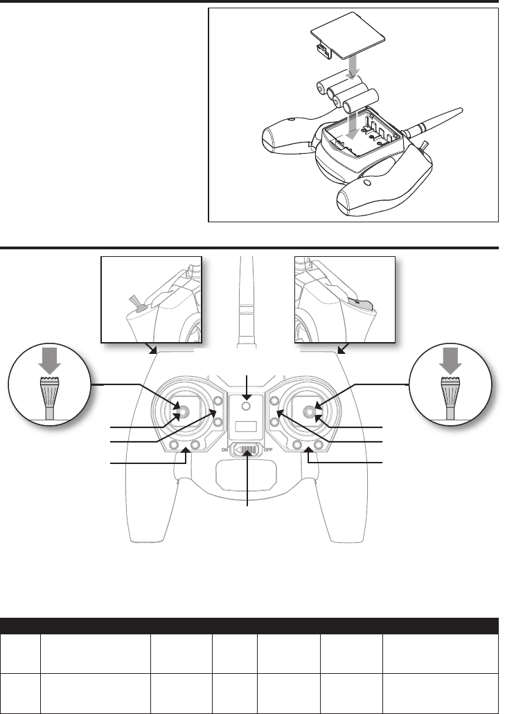
35 FR
Installation des piles de l'émetteur (RTF)
L'indicateur DEL clignote et l'émetteur bipe de
plus en plus rapidement lorsque les piles se
déchargent.
Remplacez les piles de l'émetteur lorsque celui-ci
commence à biper.
Commandes de l'émetteur (RTF)
D
E
C
B
E
A
F
Trims de réglage de vol
L'émetteur bipe à chaque fois que vous appuyez sur les
boutons de trim. La position centrale ou neutre du trim est
indiquée par une tonalité plus longue. Lorsque vous atteignez
la fi n de plage du trim, aucune tonalité ne retentira.
Sélection des débattements
La sensibilité des commandes peut être changée en effectuant
une pression sur le manche droit. La DEL de l'émetteur s'allume
fi xement quand la sensibilité est élevée (par défaut) ou clignote
quand la sensibilité est plus faible.
Interrupteur
mode de vol
Interrupteur
Affectation
Interrupteur Panique
Interrupteur
débattements
ABCDE F
Mode 1
Cyclique (Gauche/Droite)
Gaz/Pas collectif
(Monte/Descend)
Trim des gaz
Trim de
cyclique
latéral
Trim
d'anticouple
Trim de
cyclique
longitudinal
Anticouple (Gauche/Droite)
Cyclique (Avant/Arrière)
Mode 2 Cyclique (Gauche/Droit)
Cyclique (Avant/Arrière)
Trim de
cyclique
longitudinal
Trim de
cyclique
latéral
Trim
d'anticouple Trim des gaz
Anticouple (Gauche/Droite)
Gaz/Pas collectif
(Monte/Descend)
Interrupteur
ON/OFF
Indicateur DEL
alimentation/mode de vol
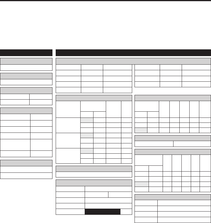
36
FR
FUNCTION LIST
DX7s, DX8
Mode de vol
Mode de vol F Mode
Auto-rotation Hold
PARAMETRES SYSTEME
Type de plateau cyclique
1 servo Normal
Type de modèle
HELI
Choix interrupteur
Écolage Aux 2
Mode de vol Gear
Gyro INH
Mix INH
Mode
auto-rotation
INH
Potentiomètre INH
Taux de rafraîchissement
11ms
DSMX
D/R & Expo
Voie
Inter. pos.
(Aileron D/R)
D/R
ExpoDX7s
DX8
Ailerons
0 100/100 +25
0 1 100/100 +25
1 2 75/75 +25
Profondeur
0 100/100 +25
0 1 100/100 +25
1 2 75/75 +25
Dérive
0 100/100 +25
0 1 100/100 +25
1 2 75/75 +25
Chronomètre
Mode à rebours
Durée 4:00 Tone
Démarrage Manche des gaz
Seuil 25%
Voie Travel Reverse
Gaz 100/100 Normal
Ailerons 100/100 Normal
Profondeur 100/100 Normal
Dérive 100/100 Normal
Voie Travel Reverse
Train 100/100 Normal
Pas 100/100 Normal
AX2 100/100 Normal
Course des servos
Courbe des gaz
Inter. pos.
(F mode)
Pt 1 Pt 2 Pt 3 Pt 4 Pt 5DX7s DX8
N N 0 25 50 75 100
1 1 100 80 75 80 100
2 100 100 100 100 100
Courbe de pas
Inter. pos.
(F mode)
Pt 1 Pt 2 Pt 3 Pt 4 Pt 5DX7s DX8
N N 30 40 50 75 100
1 1 0 25 50 75 100
2 0 25 50 75 100
HOLD HOLD 25 37 50 75 100
Auto-rotation
Gaz 0%
Gyro
Désactivé
Mixage
Voies AUX2 > GER
Taux 100% 20%
Décalage 100%
Trim INH
Position NIHM
Programmez votre émetteur avant de tenter d’effectuer
l’affectation ou de faire voler l’hélicoptère. On trouvera,
ci-après, des valeurs de programmation pour les Spektrum
DX7s, DX6, DX7, DX8, DX9, DX18 et DX20.
Les fi chiers de programme des modèles pour les émetteurs
Spektrum utilisant l’interface AirWare sont disponibles en
ligne sur www.spektrumrc.com.
DXe
Pour utiliser l’émetteur Spektrum DXe, veuillez télécharger
les réglages modèle du Blade mCP S pour la DXe disponibles
sur www.spektrumrc.com ou utiliser le câble de program-
mation adapté avec votre PC ou appareil mobile pour
programmer l’émetteur
Paramétrage de l’émetteur (BNF)
Activation du mode Panique
Bouton Écolage/Affectation
Appuyé = Mode Panique Actif
Relâché = Mode Panique Inactif
Fonctionnement des modes de vol
Interrupteur Mode de vol Pos 0 = Mode Stabilité
Pos 1 = Mode Intermédiaire
Pos 2 = Mode Agilité
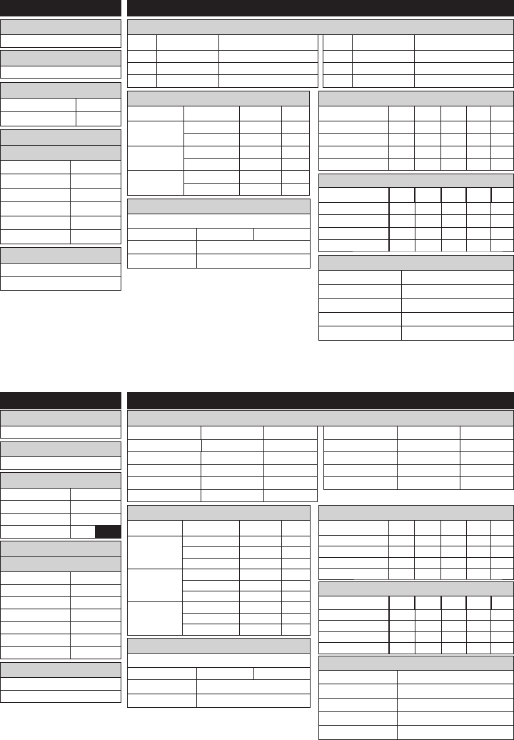
37 FR
Mode de vol
Mode de vol F Mode
Auto-rotation Hold
PARAMETRES SYSTEME
Type de plateau cyclique
1 servo Normal
Type de modèle
HELI
Chronomètre
Mode à rebours
Durée 4:00
Démarrage Manche des gaz
Seuil 25%
Unique Désactivé
Course des servos
LISTE DES FONCTIONS
DX6, DX6e
Chan Travel Reverse
THR 100/100 Normal
AIL 100/100 Normal
ELE 100/100 Normal
Chan Travel Reverse
RUD 100/100 Normal
GER 100/100 Normal
PIT 75/75 Normal
D/R & Expo
Voie
Inter. (F) pos.
D/R Expo
Ailerons 0 70/70 +30
1 100/100 +30
Profondeur 0 70/70 +30
1 100/100 +30
Dérive 0 100/100 0
1 100/100 0
Courbe des gaz
Inter. (B) pos. Pt 1 Pt 2 Pt 3 Pt 4 Pt 5
N 0 40 60 80 100
1 100 90 80 90 100
2 100 100 100 100 100
HOLD 0 0 0 0 0
Courbe de pas
Inter. (B) pos. Pt 1 Pt 2 Pt 3 Pt 4 Pt 5
N 30 40 50 75 100
1 0 25 50 75 100
2 0 25 50 75 100
HOLD 0 25 50 75 100
* Le DX6e fonctionne à un
taux de rafraîchissement
de 22ms et ne peut pas
être changé.
Taux de rafraîchissement
11ms*
DSMX
Taux de rafraîchissement
11ms*
DSMX
Voie Course Inversion
Gaz 100/100 Normal
Ailerons 100/100 Normal
Profondeur 100/100 Normal
Dérive 100/100 Normal
Train 100/100 Normal
Voie Course Inversion
Pas 75/75 Normal
AX2 100/100 Normal
AX3 100/100 Normal
AX4 100/100 Normal
Servo Setup
LISTE DES FONCTIONS
DX7G2, DX8G2, DX9, DX18, DX20
Chronomètre
Mode à rebours
Durée 4:00
Démarrage Manche des gaz
Seuil 25%
Unique Désactivé
PARAMETRES SYSTEME
Type de plateau cyclique
1 servo Normal
Type de modèle
HELI
Mode de vol
Inter. 1 Inter. B
Inter. 2 Désactivé
Auto-rotation Inter. H
01
Double-débattements et Expo
Voie Inter. (F) pos. D/R Expo
Ailerons 0 70/70 +30
1 100/100 +30
2 100/100 +30
Profondeur 0 70/70 +30
1 100/100 +30
2 100/100 +30
Dérive 0 100/100 0
1 100/100 0
2 100/100 0
Courbe des gaz
Inter. (B) pos.
Pt 1 Pt 2 Pt 3 Pt 4 Pt 5
N 0 40 60 80 100
1 100 90 80 90 100
2 100 100 100 100 100
HOLD 0 0 0 0 0
Courbe de pas
Inter. (B) pos.
Pt 1 Pt 2 Pt 3 Pt 4 Pt 5
N 30 40 50 75 100
1 0 25 50 75 100
2 0 25 50 75 100
HOLD 0 25 50 75 100
Assignation des voies
Entrées
1 Gaz Throttle
2 Ailerons Aileron
3 Profondeur Elevator
4 Dérive Rudder
5 Mode de vol Switch B
6 Collectif INH
Assignation des voies
Entrées
1 Gaz Throttle
2 Ailerons Aileron
3 Profondeur Elevator
4 Dérive Rudder
5 Train Inter. B
6 Collectif
7 AUX 2 Inter. I Mixage
GER -> GER
Taux 100% 100%
Décalage 20%
Interrupteur Interrupteur I
Mixage
GER -> GER
Taux 100% 100%
Décalage 20%
Interrupteur Interrupteur I
Activation du mode Panique
Bo uton Affectation / I:
Appuyé = Mode Panique Actif
Relâché = Mode Panique Inactif
Fonctionnement des modes de vol
Interrupteur B: Pos 0 = Mode Stabilité
Pos 1 = Mode Intermédiaire
Pos 2 = Mode Agilité
Activation du mode Panique
Bouton Affectation / I
Appuyé = Mode Panique Actif
Relâché = Mode Panique Inactif
Fonctionnement des modes de vol
Interrupteur B: Pos 0 = Mode Stabilité
Pos 1 = Mode Intermédiaire
Pos 2 = Mode Agilité
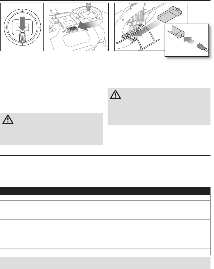
38
FR
1. Mettez la manette des gaz à la position la plus basse.
2. Mettez l’émetteur en marche.
3. Centrez tous les compensateurs. Pour l’émetteur MLP6
inclus (prêt-à-voler uniquement), les compensateurs
sont centrés lorsque vous entendez une tonalité plus
longue en appuyant sur le bouton de compensateur.
Bougez le compensateur dans les deux directions
jusqu’à ce que vous entendiez la tonalité longue.
4. Installez la batterie de vol dans le support de batterie au
bas du châssis de l’hélicoptère.
5. Raccordez le câble d’alimentation de la commande de
vol au connecteur de la batterie.
ATTENTION: un raccordement de la batterie au
panneau de commande de vol avec une polarité
inversée endommagera le panneau de commande, la
batterie ou ces deux éléments. Les dégâts résultants
d’un mauvais raccordement de la batterie ne sont pas
pris en charge dans le cadre de la garantie.
6. Posez l’hélicoptère sur une
surface plane et laissez-le
immobile jusqu’à ce que la
lumière de la DEL du récepteur soit fi xe, indiquant que
l’initialisation est terminée.
Si vous rencontrez des diffi cultés lors de l’initialisation,
consultez le Guide de dépannage au dos de ce manuel.
ATTENTION: débranchez toujours la batterie
Li-Po de l’appareil lorsqu’il n’est pas en vol pour
éviter toute décharge excessive. Les batteries
déchargées à une tension inférieure à la tension
minimale approuvée peuvent s’endommager, entraînant
une baisse de performance et un risque d’incendie
lorsque les batteries sont rechargées.
Installation de la batterie
1 2 4
5
A ectation de l’émetteur au récepteur
Procédure d’a ectation de l’émetteur MLP6DSM (RTF)
1. Débranchez la batterie de l'hélicoptère.
2. Eteingnez l'émetteur et placez tous les interrupteurs sur la position 0.
3. Branchez la batterie à l'hélicoptère. La du contrôleur 3-en-1 va fl asher après 5 secondes.
4. Appuyez et maintenez le bouton/gâchette “Panique” lors de la mise sous tension de l’émetteur.
5. Relâchez le bouton trainer (écolage) et maintenez le manche de dérive jusqu’à ce que la du contrôleur 3 en 1
s’éclaire bleue fi xe.
6. Relâchez le manche de dérive.
7. Pressez le bouton trainer (écolage). La bleue du contrôleur va fl asher pour confi rmer que l’hélicoptère est bien dans
le mode radio non programmable.
8. Débranchez la batterie de l’hélicoptère et éteignez votre émetteur.
REMARQUE: Si le plateau cyclique de déplace de haut en bas quand vous basculez l’interrupteur trainer, l’hélicoptère est en
mode émetteur programmable; refaites la précédure d’affectation.
L’affectation est le processus qui programme le récepteur pour qu’il reconnaisse le code (appelé GUID - Globally Unique
Identifi er) d’un émetteur spécifi que. Vous devez affecter l’émetteur Spektrum pour aéronef à technologie DSM2/DSMX de
votre choix au récepteur afi n d’assurer un fonctionnement correct.
Si vous avez acheté la version RTF, vous n’avez pas à effectuer cette étape.
Pour affecter ou ré-affecter votre Nano CPS à votre émetteur, suivez les instructions suivantes.
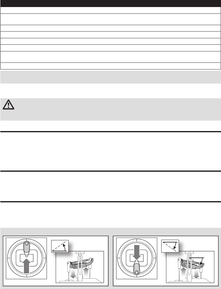
39 FR
Ce produit nécessite un émetteur compatible Spektrum DSM2/DSMX approuvé.
Pour affecter votre mCP S à votre émetteur, veuillez suivre les instructions suivantes:
Procédure d’a ectation avec une radio programmable (BNF)
1. Débranchez la batterie de vol de l’hélicoptère.
2. Si vous n’utilisez pas l’émetteur inclus avec la version prête-à-voler de l’hélicoptère, consultez le tableau de confi guration
de l’émetteur pour programmer correctement votre émetteur.
3. Mettez la manette des gaz à la position la plus basse. Mettez tous les compensateurs en position centrale pendant que l’émetteur est allumé.
4. Éteignez l’émetteur et mettez tous les commutateurs en position 0. Mettez la manette des gaz en position basse/point mort.
5. Raccordez la batterie de vol au variateur ESC. La DEL du récepteur clignote, indiquant qu’il est en mode d’affectation.
6. M ettez l’émetteur en marche en mode d’affectation.
7. Poussez totalement à droite le manche de la dérive. Maintenez le manche de dérive jusqu’à ce que la diode du contrôleur
3 en 1 s’éclaire bleue fi xe. L’hélicoptère est affecté lorsque la lumière de la DEL du récepteur se fi xe.
8. Débranchez la batterie de vol et éteignez l’émetteur.
Mode Acrobatique
Le mode Acrobatique (Mode de vol 1 ou 2) permet à l’hélicop-
tère de voler à l’envers et d’effectuer des acrobaties aériennes.
L’accélération est continue lorsque le mode acrobatique est
actif, quelle que soit la position de la manette des gaz. Éteignez
le Mode acrobatique (Mode de vol 0) pour retrouver le plein
contrôle de la manette des gaz.
ATTENTION: Si vous utilisez un émetteur Futaba avec un module Spektrum DSM2, il vous faudra inverser la
voie du manche des gaz et effectuer à nouveau l’affectation. Référez-vous au manuel d‘utilisation du module
Spektrum pour les instructions d’affectation et de sécurité failsafe. Référez-vous au manuel d’utilisation de l’émetteur
Futaba pour les instructions d’inversion de voie du manche des gaz.
La coupure des gaz sert à éviter le démarrage intempestif du
moteur. Par sécurité, enclenchez la coupure des gaz à chaque
fois que vous devez manipuler l'hélicoptère ou vérifi er les
commandes de direction.
La Coupure des gaz sert également à couper rapidement le mo-
teur si vous perdez le contrôle de l'hélicoptère, en cas de risque
d’écrasement au sol, voire des deux. Les pales continueront à
tourner brièvement lorsque la Coupure des gaz est activée. Les
commandes de pas et de direction sont toujours maintenues.
Coupure des gaz
Test des commandes
Assurez-vous que la Coupure des gaz est bien activée
lors du test des commandes. Testez les commandes
avant votre premier vol pour être sur que les servos,
tringleries et pièces fonctionnent bien. Si les commandes
ne réagissent pas comme sur l'illustration ci-dessous,
assurez-vous que l'émetteur est bien programmé avant de
passer au Test moteur.
Cyclique longitudinal
Cyclique longitudinal en bas Cyclique longitudinal en haut
Vue latérale gauche Vue latérale gauche
REMARQUE: La commande de Gaz ne s’activera pas si le manche de Gaz n’est pas à la position la plus basse et
l’interrupteur Mode Stunt doit être sur la position 0.
Si vous rencontrez des problèmes, veuillez vous référer au guide de dépannage pour d’autres instructions. En cas de
besoin, contactez le service d’assistance technique approprié.
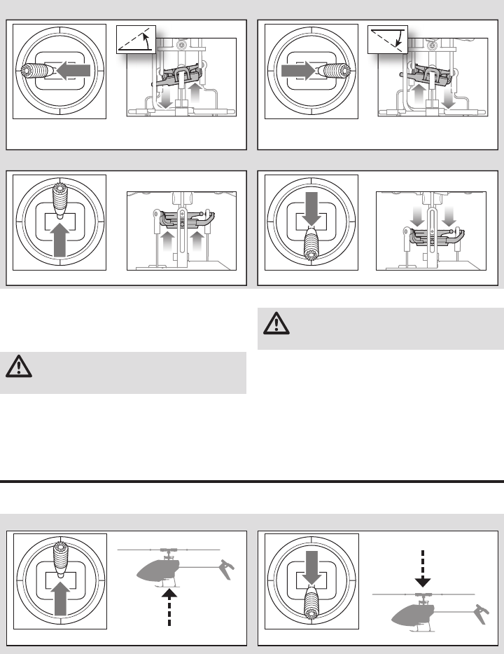
40
FR
Vue latérale gauche Vue latérale gauche
Cyclique latéral
Pas collectif
Manche du cyclique
latéral à gauche
Pas collectif levé Pas collectif baissé
Manche du cyclique
latéral à droite
Vue arrière Vue arrière
Moteur
Placez l'hélicoptère à l'extérieur sur une surface plane et propre
(béton ou bitume) libre d'obstacles. Tenez-vous toujours à l'écart
des pales quand elles sont en rotation.
ATTENTION: Maintenez toujours vos animaux à
l'écart de l'hélicoptère. Les animaux risqueraient de
se blesser s'ils attaquent ou s'approchent de l'hélicoptère.
1. Les deux moteurs bipent 3 fois lorsque le contrôleur de
l'hélicoptère est bien armé. Avant de continuer, assurez-
vous que les gaz soit au plus bas.
2. Mettez la Coupure des gaz (Throttle Hold) en position OFF.
AVERTISSEMENT: Restez à 10 mètres au moins de
l’hélicoptère lorsque le moteur tourne. N’essayez pas
de faire voler l’hélicoptère tout de suite.
3. Augmentez progressivement les gaz jusqu’à ce que les
pales se mettent en rotation. L’hélicoptère vu du dessus,
les pales principales tournent dans le sens horaire.
L’hélicoptère vu du côté droit, les pales du rotor l'anticouple
tournent dans le sens anti-horaire.
Compréhension des commandes de vol de base
Si vous n’avez pas encore bien assimilé les commandes de votre mCP S, prenez quelques minutes pour vous familiariser
avec elles avant de tenter votre premier vol.
Manche des gaz en haut Manche des gaz en bas
Monte
Collectif
Vue latérale gauche Vue latérale gauche
Descend
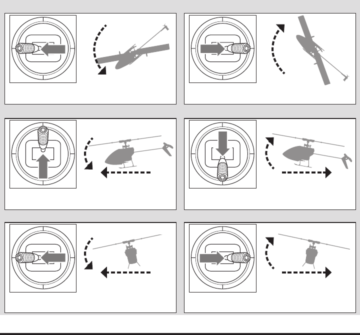
41 FR
En mode Stable, l’hélicoptère vole comme un hélicoptère
à pas fi xe (avec un angle d’inclinaison limité). Lorsque le
manche cyclique est relâché, l’appareil revient à niveau.
En mode Intermédiaire, l’angle d’inclinaison n’est pas
limité. Lorsque le manche cyclique est relâché, l’appareil
ne revient pas à niveau. La vitesse de pointe est légère-
ment plus basse et les commandes sont plus «souples».
Ce mode est idéal pour l’apprentissage du vol en avant et
des acrobaties aériennes de base, comme les renverse-
ments et les boucles.
En mode Agile, l’angle d’inclinaison n’est pas limité.
Lorsque le manche cyclique est relâché, l’appareil ne re-
vient pas à niveau. La vitesse de pointe est également plus
élevée. Ce mode est idéal pour les acrobaties aériennes en
3D, comme les retournements stationnaires et les tic tacs.
Description des modes de vol
Le nez tourne
vers la gauche
Manche d'anticouple
à gauche
Manche d'anticouple
à droite
Anticouple
Avance
Vole vers la gauche
Recule
Vole vers la droite
Manche de cyclique
longitudinal en haut
Manche du cyclique
latéral à gauche
Manche du cyclique
longitudinal en bas
Manche du cyclique
latéral à droite
Cyclique longitudinal
Cyclique latéral
Vue latérale gauche
Vue arrière
Vue du haut
Vue arrière
Vue du haut
Le nez tourne
vers la droite
Vue latérale gauche

42
FR
Consultez les lois et ordonnances locales avant
de choisir un espace de vol.
Si c’est votre premier hélicoptère à pas collectif, nous vous
conseillons de vous faire aider par un pilote d’hélicoptère expé-
rimenté ou par un club de pilotage jusqu’à ce que vous soyez
suffi samment à l’aise pour voler seul.
Nous vous recommandons de faire voler votre appareil à
l’extérieur par vent calme ou à l’intérieur dans un grand
gymnase. Évitez toujours de piloter votre appareil à proximité
d’habitations, d’arbres, de fi ls électriques et de bâtiments. Faites
aussi attention à éviter de faire voler votre appareil dans des
lieux très fréquentés comme les parcs, les cours d’école ou les
terrains de football.
La meilleure méthode est de voler depuis une surface plane
et lisse car cela permettra au modèle de glisser sans basculer.
Maintenez l’hélicoptère à environ 60 cm (2 pieds) du sol. Main-
tenez la queue pointée dans votre direction lors des premiers
vols pour garder une orientation constante des commandes.
Relâcher le levier en mode stable permettra à l’hélicoptère de
se mettre à niveau. Activer la récupération de panique mettra
rapidement l’hélicoptère à niveau. Si vous êtes désorienté alors
que vous êtes en mode stable, abaissez lentement la manette
des gaz pour vous poser en douceur.
Lors des premiers vols, ne tentez de décoller, de vous poser et
de faire du surplace qu’à un seul endroit.
Décollage
IMPORTANT : si le moteur principal ou le moteur de queue
ne démarre pas correctement lors de l’accélération, ramenez
immédiatement la manette des gaz au point mort et rées-
sayez. Si le problème persiste, débranchez la batterie de vol,
vérifi ez que le train de rouages n’est pas grippé et assurez-
vous qu’aucun fi l n’est emmêlé dans les rouages.
Posez le modèle sur une surface plane et à niveau, sans
obstacles, et reculez de 10 mètres (30 pieds). Augmentez len-
tement l’accélération jusqu’à ce que le modèle soit à environ
60 cm (2 pieds) du sol et vérifi ez le compensateur pour que le
modèle vole de la manière souhaitée. Une fois le compensa-
teur réglé, commencez à faire voler le modèle.
Vol stationnaire
En faisant de petites corrections sur l’émetteur, essayez de
maintenir l’hélicoptère à un endroit. Si vous volez par vent
calme, le modèle ne devrait nécessiter presque aucune saisie
correctrice. Après avoir déplacé le levier cyclique et l’avoir
ramené au centre, le modèle devrait se mettre à niveau. Le
modèle peut continuer de bouger en raison de l’inertie. Bougez
le levier cyclique dans la direction opposée pour arrêter le
mouvement.
Après vous être habitué au vol stationnaire, vous pouvez
essayer de faire voler le modèle vers d’autres endroits, en
maintenant la queue pointée dans votre direction à tous
moments. Vous pouvez aussi monter et descendre à l’aide
de la manette des gaz. Une fois que vous êtes habitué à ces
manœuvres, vous pouvez essayer de voler avec la queue
pointée autre part. Rappelez-vous que les saisies sur la com-
mande de vol tourneront avec l’hélicoptère, essayez donc de
toujours vous représenter les commandes par rapport au nez
de l’hélicoptère. Par exemple, la commande avant fera toujours
pointer le nez de l’hélicoptère vers le bas.
Le temps de vol moyen de l’hélicoptère à l’aide de la batterie
recommandée est d’environ 4minutes, selon l’agressivité du vol.
Coupure par tension faible (LVC)
La coupure par tension faible diminue la puissance
des moteurs lorsque la tension de la batterie s’affaiblit.
Lorsque la puissance du moteur diminue et que la DEL
sur le variateur ESC clignote, posez immédiatement
l’appareil et rechargez la batterie de vol.
Le dispositif de coupure par tension faible ne prévient
pas les décharges excessives de la batterie en période
de stockage.
REMARQUE: les vols répétés en mode coupure par
tension faible peuvent endommager la batterie.
Atterrissage
Pour vous poser, diminuez l’accélération pendant un vol
stationnaire bas. Après atterrissage, débranchez et retirez
la batterie de l’appareil après son utilisation pour éviter
qu’elle ne se décharge lentement. Rechargez entièrement
votre batterie avant de la stocker. Pendant le stockage de
la batterie, vérifi ez que son niveau de charge ne tombe
pas en dessous de 3 V par cellule.
Si vous rencontrez un problème dans n’importe quel mode
de vol, maintenez enfoncé le commutateur d’affectation/pa-
nique et mettez les leviers de commande en position neutre.
La technologie SAFE ramènera automatiquement l’appareil à
une attitude droite et à niveau, si l’appareil est à une altitude
suffi sante et qu’aucun obstacle n’est sur son chemin.
REMARQUE: n’activez pas la récupération de panique si l’héli-
coptère n’a pas assez d’altitude pour réussir une récupération.
Ramenez le levier collectif à 50% et relâchez le commuta-
teur de panique pour désactiver la récupération de panique
et revenir au mode de vol actuel.
REMARQUE: avant de relâcher le commutateur de
panique, assurez-vous que le levier collectif est revenu à
50%. Dès que le commutateur de panique est relâché, le
collectif entièrement négatif devient disponible, ce qui peut
provoquer une descente rapide du mCP S.
• La récupération de panique est conçue pour offrir au pilote
la confi ance nécessaire pour continuer à améliorer ses
compétences de pilotage.
• Mettez le levier collectif à 50% et remettez toutes les autres
commandes de l’émetteur en position neutre pour la récupé-
ration la plus rapide.
• Une fois que le modèle est droit et à niveau, le collectif négatif
est réduit pour prévenir l’atterrissage d’urgence du modèle.
Récupération de panique
Pilotage du mCP S

43 FR
Problème Cause possible Solution
La réponse aux commandes
de l’hélicoptère est incohé-
rente ou nécessite un sur-
plus de compensation pour
neutraliser le mouvement
L’appareil n’a pas été initialisé cor-
rectement ou une vibration interfère
avec le fonctionnement du capteur
Débranchez la batterie de vol, centrez le compensateur de
commande, et réinitialisez l’hélicoptère
L’hélicoptère ne
répond pas à la manette
des gaz
La manette des gaz est trop élevée
et/ou le réglage du compensateur
de gaz est trop élevé
Débranchez la batterie de vol, mettez la manette des gaz
à la position la plus basse et abaissez le compensateur
d’accélération de quelques clics. Branchez la batterie de
vol et laissez le modèle s’initialiser
L’hélicoptère a bougé lors de l’ini-
tialisation Débranchez la batterie de vol et réinitialisez l’hélicoptère
tout en l’empêchant de bouger
L’hélicoptère a un
temps de vol
ou une puissance réduits
Faible niveau de charge de la bat-
terie de vol Rechargez entièrement la batterie de vol
Batterie de vol endommagée
Remplacez la batterie de vol et suivez les instructions four-
nies pour la batterie
Les conditions météorologiques
sont peut-être trop froides Assurez-vous que la batterie est chaude (à température
ambiante) avant de l’utiliser
La DEL sur le panneau de
commande de vol clignote
rapidement et l’appareil ne
répond pas à l’émetteur
(lors de l’affectation)
L’émetteur est trop proche de
l’appareil pendant le processus
d’affectation
Éteignez l’émetteur. Éloignez l’émetteur de l’appareil.
Débranchez et rebranchez la batterie de vol de l’appareil.
Suivez les instructions d’affectation
Le commutateur ou le bouton d’affec-
tation n’a pas été maintenu pendant
la mise en marche de l’émetteur
Mettre l’émetteur hors tension et répéter le processus
d’affectation
L’appareil ou l’émetteur est trop proche
d’un grand objet métallique, d’une
source sans fi l ou d’un autre émetteur
Déplacez l’appareil et l’émetteur à un autre
endroit et réessayez l’affectation
Guide de dépannage
Liste de la maintenance et des éléments à inspecter après vol
Rotules
Contrôlez que les chapes sont correctement reliées aux rotules et qu'il n'y a pas de point dur. La rotule ne doit pas avoir un jeu
excessif, le déboîtement de la rotule durant le vol peut entraîner un crash. Remplacez les rotules usées avant leur rupture.
Nettoyage Assurez-vous que la batterie n’est pas connectée avant d’entreprendre le nettoyage. A l’aide d’une brosse douce ou
d’un chiffon sec non-pelucheux, enlevez la poussière et les débris.
Roulements Remplacez les roulements quand vous remarquez un frottement durant leur rotation.
Câblage Assurez-vous que les câbles ne bloquent pas de pièces en mouvement. Remplacez tout câble endommagé et tout
connecteur devenu lâche.
Raccords/
Pièces de
fi xation
Assurez-vous de l’absence de toute vis, bride ou connecteur desserré. Ne serrez pas excessivement les vis métalliques
dans des pièces en plastique. Serrez les vis de façon à ce que les pièces soient parfaitement jointives et ne donnez
ensuite qu’1/8ème de tour supplémentaire.
Rotors
Contrôlez l'état des pales et des autres éléments ayant une vitesse de rotation élevée. Ils peuvent présenter des fi ssures, des
bavures ou des rayures. Remplacez les pièces endommagées avant d'effectuer un nouveau vol. Contrôlez que les deux pales
principales sont serrées à leurs pieds de pales respectifs avec une tension équivalente. Quand vous inclinez l'hélicoptère, les pales
ne doivent pas pivoter sous leur propre masse. Elles ne doivent pivoter que si l'hélicoptère est légèrement secoué.
Anticouple
Contrôlez l'état du rotor d'anticouple, remplacez-le si nécessaire. Inspectez l'état de la poutre, remplacez-la si nécessaire.
Mécanique
Inspectez le châssis et du train d'atterrissage et remplacez si nécessaire. Contrôlez l'entre-dent de la couronne, qu'il
n'existe pas de point dur sur toute sa rotation. Contrôlez l'état de tous les câbles, remplacez en cas de nécessité.

44
FR
Problème Cause possible Solution
La DEL sur le panneau de
commande de vol clignote
rapidement et l’hélicoptère
ne répond pas à l’émetteur
(après l’affectation)
Moins de 5 secondes d’attente
entre la première mise en route de
l’émetteur et le raccordement de la
batterie de vol à l’hélicoptère
Laissez l’émetteur allumé. Débranchez et
rebranchez la batterie de vol de l’hélicoptère
L’hélicoptère est affecté à la mé-
moire d’un modèle différent (émet-
teurs ModelMatch seulement)
Sélectionnez la mémoire du modèle correct sur l’émet-
teur. Débranchez et rebranchez la batterie de vol de
l’hélicoptère
Niveau de charge de la batterie de
vol/de l’émetteur trop faible Remplacez/rechargez les batteries
L’appareil ou l’émetteur est trop proche
d’un grand objet métallique, d’une
source sans fi l ou d’un autre émetteur
Déplacez l’appareil et l’émetteur à un autre
endroit et réessayez la connexion
L’hélicoptère vibre ou
tremble en vol Pales du rotor, axe ou poignées de
pales endommagées
Vérifi ez que les pales du rotor principal et les poignées
de pales ne sont pas fêlées ni ébréchées. Remplacez les
pièces endommagées. Remplacez l’axe tordu
Mouvements aléatoires
en vol Vibration
Vérifi ez que le récepteur est correctement fi xé à l’hélicoptère.
Vérifi ez et équilibrez toutes les pièces tournantes. Vérifi ez
que l’arbre principal et le rotor de queue ne sont pas endom-
magés ou tordus. Vérifi ez qu’aucune pièce mécanique n’est
cassée ou endommagée, remplacez si nécessaire
Oscillation/agitation de la
queue ou mauvaise per-
formance
Rotor de queue, poutre de queue,
maillage du train principal, ou arbre
principal endommagé, boulons
desserrés, vibration
Vérifi ez que le rotor de queue n’est pas endommagé. Vérifi ez
que la poutre de queue et l’arbre principal ne sont pas fêlés.
Vérifi ez le maillage du train principal et assurez-vous qu’il est
exempt de points serrés par une rotation complète. Remplacez
les composants endommagés ou usés
Déviation par vent calme Vibration, articulation endommagée,
servo endommagé
En fonctionnement normal, les compensateurs de l’émetteur ne
devraient nécessiter aucun ajustement et les positions centrées
sont mémorisées lors de l’initialisation. Si vous trouvez qu’il est
nécessaire d’ajuster les compensateurs après le décollage,
vérifi ez l’équilibre de toutes les pièces tournantes, assurez-vous
que les articulations ne sont pas endommagées et assurez-
vous que les servos sont en bon état de fonctionnement
Déviation par vent Normal
Le modèle dévie avec le vent mais doit rester à niveau pendant
le vol. Il suffi t de maintenir le levier cyclique dans la position
nécessaire pour que le modèle reste stationnaire. Le modèle
doit être penché dans le sens du vent pour rester stationnaire.
Si le modèle reste à niveau, il déviera avec le vent
La récupération de panique
ou la remise à niveau ne
met pas le modèle à niveau
Le modèle n’a pas été initialisé sur
une surface stable et à niveau Réinitialisez le modèle sur une surface stable et à niveau
Le modèle n’a pas décollé depuis
une surface à niveau Décollez toujours depuis une surface à niveau
Vibration sévère
Arbre principal fêlé Vérifi ez que l’arbre principal n’est pas fêlé et remplacez-le
si nécessaire
Pièce tournante déséquilibrée
Vérifi ez que l’arbre principal, le rotor de queue, les pales du
rotor principal, le châssis principal et l’adaptateur ne sont pas
endommagés, remplacez si nécessaire. La vibration doit être
réduite pour la «récupération de panique» et les fonctions
de remise à niveau doivent fonctionner correctement
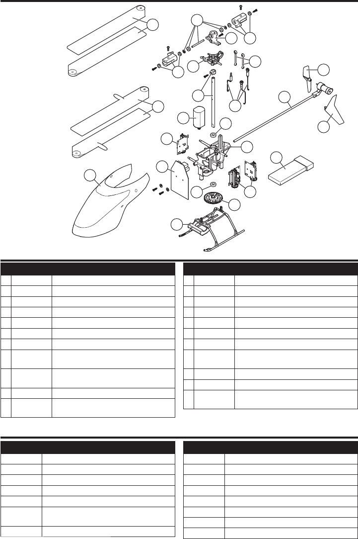
45 FR
Référence
Description
BLH3519 Voilure verte complète avec aileron vertical
BLH3602L Ensemble de poutre de queue longue
BLH3603GR Rotor de queue vert (1)
BLH3603OR Rotor de queue orange (1)
BLH3603YE Rotor de queue jaune (1)
EFLA7002UM Fil d’alimentation d’adaptateur de batterie courant
élevé 1s
EFLB2001S30
Batterie LiPo 200mAh 1S 3,7 V 30C
Référence
Description
EFLC1004 Chargeur LiPo Celctra 4 ports 1 C 3,7 V 0,3 A CC
EFLH3023
Jeu de rouages d’entraînement en fi bre de carbone
SPM20000 Système DX20 20 canaux avec AR9020 M2
SPM6650 Système DX6e 6 canaux avec AR610 RX
SPM6750 Système DX6 MD2
SPMR1000 Émetteur DXe uniquement
SPMR8000 Émetteur DX8 uniquement MD2
SPMR9910 Émetteur DX9 noir uniquement MD2
Référence Description
1 BLH3503 Moteur principal avec pignon
2 BLH3504 Patin et coussin d’atterrissage
3 BLH3505 Châssis principal avec quincaillerie
4 BLH3506 Rouage principal
5 BLH3507 Arbre principal avec collier et quincaillerie
6 BLH3508 Jeu de bielles avec liaison à bille : 3 pièces
7 BLH3509 Plateau cyclique de précision complet
8 BLH3510 Pales de rotor principal haute performance
avec quincaillerie
9 BLH3511 Pales de rotor principal pour vol rapide avec
quincaillerie
10 BLH3512 Moyeu du rotor principal avec quincaillerie
11 BLH3513 Axe à empennage avec joint torique, bague
et quincaillerie
Référence Description
12 BLH3514
Poignées de pales principales avec roulements
13 BLH3522 Ensemble de liaison de la tête du rotor (8)
14 BLH3602 Ensemble de poutre de queue
15 BLH3603 Rotor de queue
16 BLH5101 Unité de commande à barre de Bell 3-en-1
17 BLH5103 Voilure rouge avec aileron vertical
18 EFLH2215
Roulement de l’arbre externe 3 x 6 x 2 mm (2)
19
SPMSH2025L
Servo longue portée, performance linéaire 2,0
grammes Fil d’alimentation de 15 mm
20
EFLB2101S40
Batterie LiPo 210mAh 1S 3,7 V 40C
EFLC1013
Chargeur Li-Po USB 1S, 500mA
EFLRMLP6 MLP6DSM 6 canaux SAFE Tx (prêt-à-voler
uniquement)
Liste des pièces détachées
Pièces optionnelles
8
9
1
11
10
13
12
12
5
7
19
16
20
18
3
18
17
2
4
17
14
15
6
19
Vue éclatée

46
FR
Durée de la garantie
Garantie exclusive - Horizon Hobby, LLC (Horizon) garantit
que le Produit acheté (le « Produit ») sera exempt de défauts
matériels et de fabrication à sa date d’achat par l’Acheteur. La
durée de garantie correspond aux dispositions légales du pays
dans lequel le produit aété acquis. La durée de garantie est
de 6 mois et la durée d’obligation de garantie de 18 mois à
l’expiration de la période de garantie.
Limitations de la garantie
(a) La garantie est donnée à l’acheteur initial (« Acheteur ») et
n’est pas transférable. Le recours de l’acheteur consiste
en la réparation ou en l’échange dans le cadre de cette
garan tie. La garantie s’applique uniquement aux produits
achetés chez un revendeur Horizon agréé. Les ventes faites
à des tiers ne sont pas couvertes par cette garantie. Les
revendications en garantie seront acceptées sur fourniture
d’une preuve d’achat valide uniquement. Horizon se réserve
le droit de modifier les dispositions de la présente garantie
sans avis préalable et révoque alors les dispositions de
garantie existantes.
(b) Horizon n’endosse aucune garantie quant à la vendabilité
du produit ou aux capacités et à la forme physique de
l’utilisateur pour une utilisation donnée du produit. Il est de
la seule responsabilité de l’acheteur de vérifier si le produit
correspond à ses capacités et à l’utilisation prévue.
(c) Recours de l’acheteur – Il est de la seule discrétion
d’Horizon de déterminer si un produit présentant un cas
de garantie sera réparé ou échangé. Ce sont là les recours
exclusifs de l’acheteur lorsqu’un défaut est constaté.
Horizon se réserve la possibilité de vérifier tous les éléments
utilisés et susceptibles d’être intégrés dans le cas de garantie.
La décision de réparer ou de remplacer le produit est du seul
ressort d’Horizon. La garantie exclut les défauts esthétiques
ou les défauts provoqués par des cas de force majeure, une
manipulation incorrecte du produit, une utilisation incorrecte
ou commerciale de ce dernier ou encore des modifications de
quelque nature qu’elles soient.
La garantie ne couvre pas les dégâts résultant d’un montage
ou d’une manipulation erronés, d’accidents ou encore du
fonctionnement ainsi que des tentatives d’entretien ou de répa-
ration non effectuées par Horizon. Les retours effectués par
le fait de l’acheteur directement à Horizon ou à l’une de ses
représentations nationales requièrent une confirmation écrite.
Limitation des dommages
Horizon ne saurait être tenu pour responsable de dommages
conséquents directs ou indirects, de pertes de revenus ou
de pertes commerciales, liés de quelque manière que ce
soit au produit et ce, indépendamment du fait qu’un recours
puisse être formulé en relation avec un contrat, la garantie ou
l’obligation de garantie. Par ailleurs, Horizon n’acceptera pas
de recours issus d’un cas de garantie lorsque ces recours
dépassent la valeur unitaire du produit. Horizon n’exerce
aucune influence sur le montage, l’utilisation ou la main-
tenance du produit ou sur d’éventuelles combinaisons de
produits choisies par l’acheteur. Horizon ne prend en compte
aucune garantie et n‘accepte aucun recours pour les blessures
ou les dommages pouvant en résulter. Horizon Hobby ne sau-
rait être tenu responsable d’une utilisation ne respectant pas
les lois, les règles ou règlementations en vigueur.
En utilisant et en montant le produit, l’acheteur accepte sans
restriction ni réserve toutes les dispositions relatives à la
garantie figurant dans le présent document. Si vous n’êtes
pas prêt, en tant qu’acheteur, à accepter ces dispositions en
relation avec l’utilisation du produit, nous vous demandons de
restituer au vendeur le produit complet, non utilisé et dans son
emballage d’origine.
Indications relatives à la sécurité
Ceci est un produit de loisirs perfectionné et non un jouet.
Il doit être utilisé avec précaution et bon sens et néces-
site quelques aptitudes mécaniques ainsi que mentales.
L’incapacité à utiliser le produit de manière sure et raison-
nable peut provoquer des blessures et des dégâts matériels
conséquents. Ce produit n’est pas destiné à être utilisé par des
enfants sans la surveillance par un tuteur. La notice d’utilisation
contient des indications relatives à la sécurité ainsi que des
indications concernant la maintenance et le fonctionnement du
produit. Il est absolument indispensable de lire et de compren-
dre ces indications avant la première mise en service. C’est
uniquement ainsi qu’il sera possible d’éviter une manipulation
erronée et des accidents entraînant des blessures et des
dégâts. Horizon Hobby ne saurait être tenu responsable d’une
utilisation ne respectant pas les lois, les règles ou règlementa-
tions en vigueur.
Questions, assistance et réparations
Votre revendeur spécialisé local et le point de vente ne peu-
vent effectuer une estimation d’éligibilité à l’application de la
garantie sans avoir consulté Horizon. Cela vaut également pour
les réparations sous garantie. Vous voudrez bien, dans un tel
cas, contacter le revendeur qui conviendra avec Horizon d’une
décision appropriée, destinée à vous aider le plus rapidement
possible.
Maintenance et réparation
Si votre produit doit faire l’objet d’une maintenance ou d’une
réparation, adressez-vous soit à votre revendeur spécialisé,
soit directement à Horizon. Emballez le produit soigneuse-
ment. Veuillez noter que le carton d’emballage d’origine ne
suffit pas, en règle générale, à protéger le produit des dégâts
pouvant survenir pendant le transport. Faites appel à un
service de messagerie proposant une fonction de suivi et une
assurance, puisque Horizon ne prend aucune responsabilité
pour l’expédition du produit jusqu’à sa réception acceptée.
Veuillez joindre une preuve d’achat, une description détaillée
des défauts ainsi qu’une liste de tous les éléments distincts
envoyés. Nous avons de plus besoin d’une adresse complète,
d’un numéro de téléphone (pour demander des renseigne-
ments) et d’une adresse de courriel.
Garantie et réparations
Les demandes en garantie seront uniquement traitées en
présence d’une preuve d’achat originale émanant d’un
revendeur spécialisé agréé, sur laquelle figurent le nom de
l’acheteur ainsi que la date d’achat. Si le cas de garantie est
confirmé, le produit sera réparé. Cette décision relève unique-
ment d’Horizon Hobby.
Réparations payantes
En cas de réparation payante, nous établissons un devis que
nous transmettons à votre revendeur. La réparation sera seule-
ment effectuée après que nous ayons reçu la confirmation
du revendeur. Le prix de la réparation devra être acquitté au
revendeur. Pour les réparations payantes, nous facturons au
minimum 30 minutes de travail en atelier ainsi que les frais de
réexpédition. En l’absence d’un accord pour la réparation dans
un délai de 90 jours, nous nous réservons la possibilité de
détruire le produit ou de l’utiliser autrement.
ATTENTION: Nous n’effectuons de réparations payantes
que pour les composants électroniques et les moteurs.
Les réparations touchant à la mécanique, en particulier
celles des hélicoptères et des voitures radiocomman-
dées, sont extrêmement coûteuses et doivent par con-
séquent être effectuées par l’acheteur lui-même. 10/15
Garantie et réparations
47 FR
Informations IC
RTF l'émetteur IC: 6157A-BRWDXMT
L’hélicoptère IC: 6157A-BLH5100
Cet appareil est conforme aux exigences de la norme
RSS d'Industrie Canada applicables aux appareils radio
exempts de licence. L'exploitation est autorisée aux deux
conditions suivantes:
(1) l’appareil ne doit pas produire d'interférences nuisibles,
et (2) cet appareil doit accepter toute interférence reçue,
y compris des interférences qui peuvent provoquer un
fonctionnement non désiré.
Informations de conformité pour l’Union européenne
Déclaration de conformité de l’Union européenne:
Horizon Hobby, LLC déclare par la présente
que ce produit est en conformité avec les
exigences essentielles et les autres dispositions des direc-
tives RED et CEM.
Une copie de la déclaration de conformité européenne est
disponible en ligne sur:
http://www.horizonhobby.com/content/support-render-compliance.
Instructions relatives à l’élimination des D3E pour les utilisateurs résidant dans l’Union européenne
Ce produit ne doit pas être éliminé avec
d’autres déchets. Il relève de la responsabilité
de l’utilisateur d’éliminer les équipements mis
au rebut en les remettant à un point de col-
lecte désigné en vue du recyclage des déchets
d’équipements électriques et électroniques.
La collecte et le recyclage séparés de vos
équipements au moment de leur élimination aideront à pré-
server les ressources naturelles et à garantir que les déchets
seront recyclés de manière à protéger la santé humaine et
l’environnement. Pour plus d’informations quant aux lieux de
dépôt de vos équipements mis au rebut en vue du recyclage,
veuillez contacter votre mairie, votre service de traitement
des ordures ménagères ou le magasin dans lequel vous avez
acheté le produit.
Pays d’achat Horizon Hobby Numéro de téléphone/E-mail Adresse
Union
européenne
Horizon Technischer Service service@horizonhobby.eu Hanskampring 9
D 22885 Barsbüttel, Germany
Sales: Horizon Hobby GmbH +49 (0) 4121 2655 100
Coordonnées de garantie et réparations

48
IT
AVVISO
Convenzioni terminologiche
Tutte le istruzioni, le garanzie e gli altri documenti pertinenti sono soggetti a cambiamenti a totale discrezione di
Horizon Hobby, LLC. Per una documentazione aggiornata sul prodotto, visitare il sito horizonhobby.com e fare clic sulla
sezione Support del prodotto.
Nella documentazione relativa al prodotto vengono utilizzati i seguenti termini per indicare i vari livelli di pericolo potenziale
durante l’uso del prodotto:
AVVERTENZA: indica procedure che, se non debitamente seguite, determinano il rischio di danni alle cose, danni collaterali e
gravi lesioni alle persone O il rischio elevato di lesioni superfi ciali alle persone.
ATTENZIONE: indica procedure che, se non debitamente seguite, determinano il rischio di danni alle cose E di gravi lesioni
alle persone.
AVVISO: indica procedure che, se non debitamente seguite, possono determinare il rischio di danni alle cose E il rischio
minimo o nullo di lesioni alle persone.
• Mantenere sempre un perimetro di sicurezza intorno al
modello per evitare collisioni o ferite. Questo modello
funziona con comandi radio soggetti alle interferenze di
altri dispositivi non controllabili dall’utente. Leinterferenze
possono provocare una momentanea perdita di controllo.
• Utilizzare sempre il modello in spazi aperti liberi davei-
coli, traffi co o persone.
• Seguire sempre scrupolosamente le istruzioni e le av-
vertenze relative al e a tutti gli accessori (caricabatterie,
pacchi batterie ricaricabili ecc.).
• Tenere sempre le sostanze chimiche, i componenti
dipiccole dimensioni e i componenti elettrici fuori
dallaportata dei bambini.
• Evitare sempre il contatto con l’acqua di tutti i dispositivi che
non sono stati specifi catamente progettati per funzionare in
acqua. L’umidità danneggia le parti elettroniche.
• Non mettere in bocca alcun componente del modello
poiché potrebbe causare lesioni gravi o persino la morte.
• Non far volare il modello se le batterie
del trasmettitore sono poco cariche.
• Tenere sempre il modello a vista e sotto controllo.
• Abbassare sempre completamente lo stick del motore,
quando le eliche rischiano di toccare un oggetto o il suolo.
• Utilizzare sempre batterie completamente cariche.
• Tenere sempre acceso il trasmettitore mentre il velivolo
è alimentato.
• Rimuovere sempre le batterie prima dello smontaggio.
• Tenere sempre pulite le parti mobili.
• Tenere sempre asciutte le parti.
• Lasciare sempre raffreddare le parti dopo l’uso prima
ditoccarle.
• Rimuovere sempre le batterie dopo l’uso.
• Non far volare mai il velivolo con il cablaggio danneggiato.
• Non toccare mai le parti mobili.
Almeno 14 anni. Non è un giocattolo.
AVVERTENZA: leggere TUTTO il manuale di istruzioni e familiarizzare con le caratteristiche del prodotto prima
di farlo funzionare. Un uso improprio del prodotto può causare danni al prodotto stesso e alle altre cose e gravi
lesioni alle persone.
Questo è un prodotto sofi sticato per appassionati di modellismo. Deve essere azionato in maniera attenta e responsabile e
richiede alcune conoscenze basilari di meccanica. L’uso improprio o irresponsabile di questo prodotto può causare lesioni
alle persone e danni al prodotto stesso o alle altre cose. Questo prodotto non deve essere utilizzato dai bambini senza la
diretta supervisione di un adulto. Non tentare in nessun caso di smontare il prodotto, di utilizzarlo con componenti non
compatibili odi potenziarlo senza previa approvazione di Horizon Hobby, LLC. Questo manuale contiene le istruzioni per
la sicurezza, l’uso e la manutenzione del prodotto. È fondamentale leggere e seguire tutte le istruzioni e le avvertenze
del manuale prima di montare, impostare o utilizzare il prodotto, alfi ne di utilizzarlo correttamente e di evitare di causare
danni alle cose o gravi lesioni alle persone.
Ulteriori precauzioni per la sicurezza e avvertenze

49 IT
• Elicottero Blade mCP S
• 2 Batterie Li-Po 210 mAh 1S 3,7 V 40C
• Caricabatteria USB Li-Po 1S (Solo RTF)
• Trasmittente MLP6DSM (Solo RTF)
• 4 batterie AA (Solo RTF)
Contenuto della scatola ................................................... 49
Preparazione al primo volo .............................................. 50
Controlli prima del volo ................................................... 50
Avvertenze per la carica .................................................. 50
Carica della batteria ........................................................ 50
Installazione delle batterie della trasmittente (RTF) .......... 51
Comandi della trasmittente (RTF) .................................... 51
Impostazione della trasmittente (BNF) ............................. 52
Installazione della batteria di volo ...................................54
Connessione trasmittente e ricevente (binding) ............... 54
Throttle Hold ................................................................... 55
Modalità Acrobatica ........................................................ 55
Test di controllo della direzione ....................................... 56
Comandi di volo primari .................................................. 57
Descrizione delle modalità di volo ................................... 57
Modalità Antipanico ........................................................ 58
In volo con il Blade mCP S .............................................. 58
Controlli e manutenzione dopo il volo .............................. 59
Guida alla risoluzione dei problemi .................................. 59
Vista esplosa ..................................................................61
Elenco delle parti ............................................................ 61
Parti opzionali ................................................................. 61
Garanzia ......................................................................... 62
Garanzia e Assistenza - Informazioni per i contatti .......... 63
Informazioni sulla conformità per l’Unione Europea ......... 63
Contenuto della scatola
Indice
Per ricevere gli aggiornamenti del prodotto, le offerte speciali e altro, bisogna registrarlo su www.bladehelis.com
Lunghezza 240mm
Altezza 90 mm
Diametro rotore principale 240mm
Diametro rotore di coda 40mm
Peso in volo 49 g
Specifiche
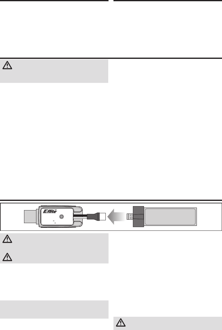
50
IT
Carica della batteria
USB Li-Po
Charger
EFLC1013
SOLID RED LED
–Charging
DC Input:5.0V 500mA
DC Output:4.2V 500mA
LED OFF
–Charge
Complete
ATTENZIONE: usare solo caricatori progettati
specifi camente per queste batterie LiPo. In caso
contrario si potrebbero incendiare procurando danni.
ATTENZIONE: non superare le correnti di carica
raccomandate.
Il caricabatteria (EFLC1013) incluso in questa confezione è
stato creato per caricare in modo sicuro la batteria di volo 1S
3,7V 210mAh 40C LiPo. Fare riferimento alle avvertenze per
la carica. Si raccomanda di caricare la batteria mentre si is-
peziona il modello perché di seguito verrà chiesto di verifi care
alcune funzioni in cui serve la batteria carica.
AVVISO: caricare solo batterie che siano fredde al tatto e che
non siano danneggiate. Controllare la batteria per verifi care
che non sia gonfi a, piegata, rotta o bucata.
1. Inserire il caricatore in una porta USB. Esso userà solo
l'alimentazione ma non si collegherà al computer. Si
possono usare anche alimentatori USB come quelli usati
per caricare i telefoni cellulari.
2. Connettere la batteria al caricabatteria come illustrato
sopra. Se si fanno correttamente tutti i collegamenti, il LED
sul caricatore si accende in rosso, indicando che la carica
è iniziata. Per caricare una batteria scarica (non sovra
scaricata) da 210mAh ci vogliono circa 30 minuti. Il LED si
spegne quando la carica è terminata.
Carica in corso (acceso rosso)
Carica massima (spento)
3. Scollegare sempre la batteria dal caricatore immediata-
mente dopo il termine della carica.
ATTENZIONE: quando la carica è terminata,
scollegare subito la batteria dal caricatore.
Preparazione al primo volo
• Estrarre il contenuto dalla scatola e controllarlo
• Caricare la batteria di volo
• Programmare la trasmittente computerizzata (solo BNF)
• Installare la batteria di volo sull'elicottero
(dopo averla caricata completamente)
• Connettere la trasmittente (binding) (solo BNF)
• Acquisire dimestichezza con i comandi
• Cercare un'area adatta per volare
Controlli prima del volo
❏Accendere sempre prima la trasmittente
❏ Collegare la batteria di volo al cavo dell'ESC
❏ Aspettare che la ricevente e l'ESC si inizializzino e si
armino correttamente
❏Fare volare il modello
❏Far atterrare il modello
❏ Scollegare la batteria di volo dall'ESC
❏Spegnere sempre la trasmittente per ultima
ATTENZIONE: seguire attentamente tutte le
istruzioni e avvertenze. L’uso improprio delle
batterie LiPo può provocare incendi, lesioni alle persone
e/o danni alle cose.
• NON LASCIARE MAI INCUSTODITE LE BATTERIE IN CARICA.
• NON CARICARE MAI LE BATTERIE DURANTE LA NOTTE.
• Maneggiando, caricando o usando la batteria LiPo
fornita in dotazione, l'utente si assume tutti i rischi con-
nessi all'utilizzo delle batterie al litio.
• Se in qualsiasi momento la batteria inizia a deformarsi
o gonfi arsi, interromperne immediatamente l’uso. Se
la batteria è in carica o si sta scaricando, interrompere
e scollegare. L'utilizzo, la carica o la scarica di una
batteria che ha iniziato a deformarsi o a gonfi arsi può
provocare incendi.
• Per ottenere i migliori risultati, conservare sempre le
batterie in un luogo asciutto e a temperatura ambiente.
• La temperatura per conservare temporaneamente le batterie
o per trasportarle deve essere compresa tra 5 e 49 °C.
• Non conservare la batteria o il modello all'interno di
un'automobile o alla luce diretta del sole. All'interno di
un'automobile calda, la batteria potrebbe danneggiarsi
o prendere fuoco.
• Caricare sempre le batterie lontano da materiali infi ammabili.
• Controllare sempre la batteria prima di caricarla.
• Scollegare sempre la batteria quando ha terminato la
carica e lasciare che il caricabatteria si raffreddi tra una
carica e l’altra.
• Durante la carica, controllare costantemente la tem-
peratura delle batterie.
• USARE SOLO UN CARICABATTERIA SPECIFICO PER LE BATTERIE
LIPO. In caso contrario, la batteria potrebbe prendere fuoco,
causando lesioni alle persone e/o danni alle cose.
• Non scaricare le celle LiPo al di sotto dei 3 V sotto carico.
• Non coprire le etichette di avvertenza con fascette a strappo.
• Non caricare le batterie oltre i livelli raccomandati.
• Non caricare mai batterie danneggiate.
• Non provare a smontare o modifi care il caricabatteria.
• Non permettere ai minori di caricare le batterie.
• Non caricare mai le batterie in luoghi estremamente caldi o
freddi (si raccomanda una temperatura compresa tra 5 e 49 °C)
o esposti alla luce diretta del sole.
Avvertenze per la carica
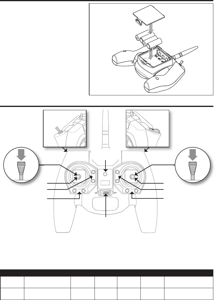
51 IT
Installazione delle batterie della trasmittente (RTF)
Il LED lampeggia e la trasmittente emette un bip
sempre più veloce man mano che il voltaggio
della batteria scende.
Sostituire le batterie della trasmittente quando la
stessa inizia a emettere bip.
Comandi della trasmittente (RTF)
D
E
C
B
E
A
F
Regolazione dei trim
La trasmittente emette un bip ogni volta che i rispettivi
pulsanti dei trim vengono premuti. Se un trim è in posizione
centrale o neutra, il suono emesso dalla trasmittente è lungo.
La fi ne dell'escursione del trim è indicata dall'assenza di
suoni quando si preme il rispettivo pulsante.
Scelta dei Dual Rate
La sensibilità dei comandi può essere modifi cata premendo
e rilasciando lo stick di comando destro. Il LED sulla
trasmittente sarà fi sso se la sensibilità è alta (predefi nita) e
lampeggiante se la sensibilità è bassa.
Interruttore
modalità di volo
Interruttore
Dual Rate
ABCDE F
Modalità 1 Alettone (destro/sinistro)
Gas/collettivo (su/giù) Trim gas Trim
alettone
Trim
direzionale
Trim
elevatore
Direzionale (sinistro/destro)
Elevatore (su/giù)
Modalità 2 Alettone (sinistro/destro)
Elevatore (su/giù)
Trim
elevatore
Trim
alettone
Trim
direzionale Trim gas Direzionale (sinistro/destro)
Gas/collettivo (su/giù)
Interruttore
ON/OFF
LED accensione/
modalità di volo
Interruttore Panic
Interruttore
Bind
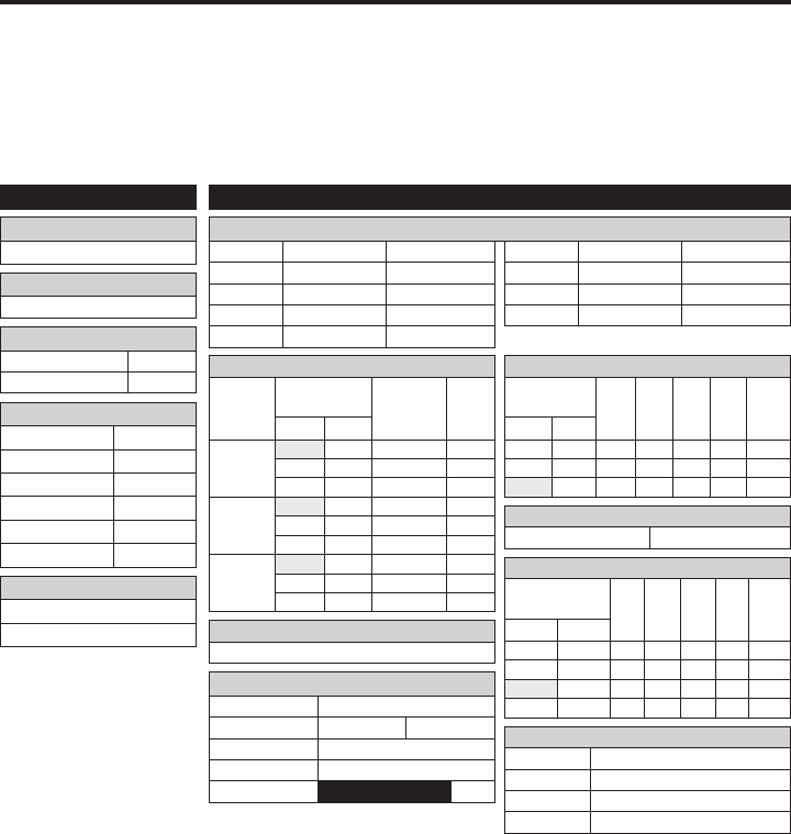
52
IT
FUNCTION LIST
DX7s, DX8
F-Mode Setup
Modalità di volo F Mode
Hold Hold
SETUP LIST
Tipo di piatto
1 servo Normal
Tipo di modello
HELI
SW Select
Trainer Aux 2
F Mode Gear
Gyro INH
Mix INH
Hold INH
Knob INH
Frame Rate
11ms
DSMX
D/R & Expo
Can.
Pos. Interr.
(Ail D/R)
D/R
ExpoDX7s
DX8
AILE
0 100/100 +25
0 1 100/100 +25
1 2 75/75 +25
ELEV
0 100/100 +25
0 1 100/100 +25
1 2 75/75 +25
RUDD
0 100/100 +25
0 1 100/100 +25
1 2 75/75 +25
Timer
Mode Conteggio a scendere
Time 4:00 Tone
Start Motore in avanti
Over 25%
Can. Corsa Reverse
THR 100/100 Normal
AIL 100/100 Normal
ELE 100/100 Normal
RUD 100/100 Normal
Can. Corsa Reverse
GER 100/100 Normal
PIT 100/100 Normal
AX2 100/100 Normal
Servo Setup
Throttle Curve
Pos. Interr.
(F Mode)
Pt 1 Pt 2 Pt 3 Pt 4 Pt 5DX7s DX8
N N 0 25 50 75 100
1 1 100 80 75 80 100
2 100 100 100 100 100
Pitch Curve
Pos. Interr.
(F Mode)
Pt 1 Pt 2 Pt 3 Pt 4 Pt 5DX7s DX8
N N 30 40 50 75 100
1 1 0 25 50 75 100
2 0 25 50 75 100
HOLD HOLD 25 37 50 75 100
Throttle Hold
Motore 0%
Gyro
Inibito
Mixing
Canali AUX2 > GER
Corsa 100% 20%
Offset 100%
Trim INH
Posizione NIHM
Prima di provare a connettere o a far volare l'elicottero,
programmare la trasmittente. I valori necessari per program-
mare la trasmittente sono visualizzati di seguito per le
versioni Spektrum DX7s, DX6, DX7, DX8, DX9, DX18 e DX20.
I fi le per i modelli che usano le trasmittenti Spektrum
con il software AirWare possono essere scaricati dal sito
www.spektrumrc.com.
DXe
Per usare la trasmittente Spektrum DXe, scaricare la
confi gurazione del modello per Blade mCP S disponibile sul
sito www.spektrumrc.com o programmare la trasmittente
usando il cavo di programmazione adatto e l’app per PC o
dispositivi mobili.
Impostazione della trasmittente (BNF)
Funzionamento modalità antipanico
Pulsante Trainer/Bind
Premuto = funzione antipanico attivata
Rilasciato = funzione antipanico disattivata
Funzionamento modalità di volo
Interr. Flight Mode Pos. 0 = mod. Stability
Pos. 1 = mod. Intermedio
Pos. 2 = mod. Agility
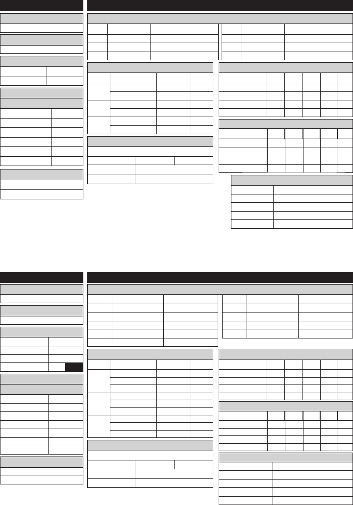
53 IT
F-Mode Setup
Flight Mode F Mode
Hold Hold
SETUP LIST
Tipo di piatto
1 servo Normal
Tipo di modello
HELI
Timer
Mode Conteggio a scendere
Time 4:00 Tone
Start Motore in avanti
Over 25%
One Time Inibito
Servo Setup
FUNCTION LIST
DX6, DX6e
Can. Travel Reverse
THR 100/100 Normal
AIL 100/100 Normal
ELE 100/100 Normal
Can. Travel Reverse
RUD 100/100 Normal
GER 100/100 Normal
PIT 75/75 Normal
D/R & Expo
Can. Pos. Interr. (F) D/R Expo
AILE 0 70/70 +30
1 100/100 +30
ELEV 0 70/70 +30
1 100/100 +30
RUDD 0 100/100 0
1 100/100 0
Curva del motore
Pos. Interr. (B) Pt 1 Pt 2 Pt 3 Pt 4 Pt 5
N 0 40 60 80 100
1 100 90 80 90 100
2 100 100 100 100 100
HOLD 0 0 0 0 0
Curva del passo
Pos. Interr. (B) Pt 1 Pt 2 Pt 3 Pt 4 Pt 5
N 30 40 50 75 100
1 0 25 50 75 100
2 0 25 50 75 100
HOLD 0 25 50 75 100
* Il DX6e opera a un Frame
Rate de 22ms e non può
essere modifi cata.
Frame Rate
11ms*
DSMX
Frame Rate
11ms*
DSMX
Can. Corsa Reverse
THR 100/100 Normal
AIL 100/100 Normal
ELE 100/100 Normal
RUD 100/100 Normal
GER 100/100 Normal
Can. Corsa Reverse
PIT 75/75 Normal
AX2 100/100 Normal
AX3 100/100 Normal
AX4 100/100 Normal
Servo Setup
FUNCTION LIST
DX7G2, DX8G2, DX9, DX18, DX20
Timer
Mode Conteggio a scendere
Time 4:00 Tone
Start Motore in avanti
Over 25%
One Time Inibito
SYSTEM SETUP
Tipo di piatto
1 servo Normal
Tipo di modello
HELI
F-Mode Setup
Switch 1 Interr. B
Switch 2 INH
Hold Switch Interr. H
01
D/R & Expo
Can. Pos. Interr. (F) D/R Expo
AILE 0 70/70 +30
1 100/100 +30
2 100/100 +30
ELEV 0 70/70 +30
1 100/100 +30
2 100/100 +30
RUDD 0 100/100 0
1 100/100 0
2 100/100 0
Curva del motore
Pos. Interr. (B) Pt 1 Pt 2 Pt 3 Pt 4 Pt 5
N 0 40 60 80 100
1 100 90 80 90 100
2 100 100 100 100 100
HOLD 0 0 0 0 0
Curva del passo
Pos. Interr. (B) Pt 1 Pt 2 Pt 3 Pt 4 Pt 5
N 30 40 50 75 100
1 0 25 50 75 100
2 0 25 50 75 100
HOLD 0 25 50 75 100
Assegnazione Canale
Input Canale
1 Motore Throttle
2 Alettoni Aileron
3 Elevatore Elevator
4 Timone Rudder
5 Modalità di volo Switch B
6 Collettivo INH
Assegnazione Canale
Input Canale
1 Throttle Throttle
2 Aileron Aileron
3 Elevator Elevator
4 Rudder Rudder
5 Gear Interr. B
6 AUX 1 INH
7 AUX 2 Interr. I Miscelazioni
GER -> GER
Corsa 100% 100%
Offset 20%
Interr. Interr. I
Miscelazioni
GER -> GER
Corsa 100% 100%
Offset 20%
Interr. Interr. I
Funzionamento modalità antipanico
Pu lsante Bind/I
Premuto = funzione antipanico attivata
Rilasciato = funzione antipanico disattivata
Funzionamento modalità di volo
Interr. B Pos. 0 = mod. Stability
Pos. 1 = mod. Intermedio
Pos. 2 = mod. Agility
Funzionamento modalità antipanico
Pulsante Bind/I
Premuto = funzione antipanico attivata
Rilasciato = funzione antipanico disattivata
Funzionamento modalità di volo
Interr. B Pos. 0 = mod. Stability
Pos. 1 = mod. Intermedio
Pos. 2 = mod. Agility
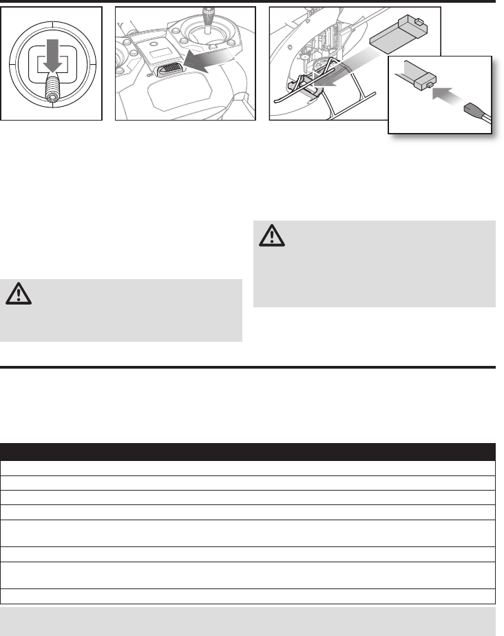
54
IT
1. Abbassare lo stick della manetta portandolo sulla
posizione più bassa.
2. Accendere la trasmittente.
3. Centrare tutti i trim. Per la trasmittente MLP6 in dota-
zione (solo RTF), i trim sono centrati quando si sente
un segnale acustico prolungato premendo il pulsante
relativo. Muovere il trim in entrambe le direzioni fi no a
sentire il segnale acustico prolungato.
4. Inserire la batteria di volo nel supporto batteria nella
parte inferiore del telaio dell'elicottero.
5. Collegare il cavo di alimentazione del controllo di volo al
connettore della batteria.
ATTENZIONE: collegare la batteria alla scheda di
controllo del volo con polarità inversa
danneggerà la scheda di controllo, la batteria o entrambi
i componenti. I danni causati da un collegamento errato
della batteria non sono coperti dalla garanzia.
6. Posizionare l'elicottero su
una superfi cie piana e non
muoverlo fi no a quando
il LED del ricevitore si accenderà con luce fi ssa, ad
indicare il completamento dell'inizializzazione.
In caso di problemi durante la fase di inizializzazione,
consultare la Guida per la risoluzione dei problemi in calce
al presente manuale.
ATTENZIONE: scollegare sempre la batteria
Li-Po dall'aeromodello quando non viene
utilizzato, per evitare che si scarichi eccessivamente. Le
batterie che si scaricano raggiungendo un voltaggio
inferiore al minimo consentito possono danneggiarsi,
con conseguente rendimento inferiore e potenziale
rischio di incendio quando vengono caricate.
Installazione della batteria di volo
1 2 4
5
Connessione trasmittente e ricevente (binding)
Procedura del Binding per radio MLP6DSM (RTF)
1. Scollega la batteria di volo dall’elicottero.
2. Spegni il trasmettitore e sposta tutti gli interruttori in posizione 0.
3. Collega la batteria di volo nell’elicottero. Il LED dell’unità di controllo 3-in-1 lampeggia dopo 5 secondi.
4. Tenere premuto il tasto “panic” mentre si accende il trasmettitore.
5. Rilasciare il bottone del trainer. Continuare a tenere la leva verso la sinistra fi no a quando il LED blu sull’unità di controllo
3-in-1 e’ acceso.
6. Rilasciare la leva del timone.
7. Spingere il bottone del trainer. Il Led blu dell’unità di controllo 3-in-1 lampeggerà confermando che l’elicottero è nel modo
senza computer.
8. Scollega la batteria di volo e spegni il trasmettitore.
AVVISO: se il piatto ciclico si muove su e giù quando si sposta l’interruttore trainer, l’elicottero si trova in modalità
trasmettitore computer; ripeti la procedura di binding.
Il binding è il processo di programmazione del ricevitore dell’unità di controllo per il riconoscimento del codice
GUID (Globally Unique Identifi er) di una particolare trasmittente. Per ottenere un funzionamento corretto è necessario
effettuare il “binding” al ricevitore utilizzando un trasmettitore per velivoli dotato di tecnologia Spektrum DSM2/DSMX.
Se hai acquistato un modello RTF, il binding del trasmettitore è stato effettuato in fabbrica.
Per collegare o ricollegare l’Nano CPS al trasmettitore MLP6DSM segui le istruzioni elencate di seguito:
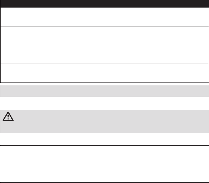
55 IT
Questo prodotto richiede una trasmittente compatibile approvata con tecnologia Spektrum DSM2/DSMX.
Per connettere (bind) il proprio mCP S al trasmettitore scelto, osservare le seguenti indicazioni:
Procedura del Binding per trasmittenti computerizzate (BNF)
1. Scollegare la batteria di volo dall'elicottero.
2. Se non si utilizza la trasmittente fornita in dotazione con la versione RTF dell'elicottero, consultare la Tabella di confi gurazio-
ne della trasmittente per programmare la trasmittente in modo corretto.
3. Abbassare lo stick della manetta portandolo sulla posizione più bassa. Spostare tutti i trim in posizione centrale mentre la
trasmittente è accesa.
4. Spegnere la trasmittente e spostare tutti gli interruttori in posizione 0. Spostare la manetta in posizione bassa/OFF.
5. Collegare la batteria di volo all'ESC (controllo elettronico della velocità). Il LED del ricevitore lampeggia, ad indicare che si
trova in modalità di connessione.
6. Accendere la trasmittente in modalità di connessione.
7. Muovere la leva del timone verso destra. Continuare a tenere la leva verso la destra fi no a quando il LED blu sull’unità di
controllo 3-in-1 è acceso. L'elicottero è connesso quando il LED sul ricevitore si accende con luce fi ssa.
8. Scollegare la batteria di volo e spegnere la trasmittente.
Modalità Acrobatica
La modalità Acrobatica (Modalità di volo 1 o 2) consente
all'elicottero di volare in posizione capovolta ed eseguire
manovre acrobatiche. La manetta funziona in modo conti-
nuo quando la modalità Stunt è attiva,
indipendentemente dalla posizione dello stick. Disattivare
la modalità Acrobatica (Modalità di volo 0) per restituire
pieno controllo allo stick della manetta.
ATTENZIONE: quando si usa una trasmittente Futaba con un modulo Spektrum DSM2, è necessario invertire il
canale del gas e ripetere la procedura di connessione. Per trovare le istruzioni relative alla connessione e al
failsafe, consultare il manuale del modulo Spektrum. Per trovare le istruzioni relative all'inversione del canale del gas,
consultare il manuale della trasmittente Futaba.
L'interruttore Throttle Hold viene utilizzato per impedire al
motore di accendersi inavvertitamente. Per sicurezza posizionare
l'interruttore Throttle Hold su ON ogni volta che è necessario
maneggiare l'elicottero o controllare la direzione dei comandi.
L'interruttore Throttle Hold viene utilizzato anche per spegnere
il motore velocemente se l'elicottero è fuori controllo, rischia di
cadere o in concomitanza di ambedue i casi. Dopo aver attivato
l'interruttore Throttle Hold, le pale continueranno a girare breve-
mente. I comandi del passo e della direzione vengono mantenuti.
Throttle Hold
AVVISO: L’accellerazione non partirà se la leva dell’accellerazione non è impostata nella posizione minima ed il
pulsante Stunt non è impostato sulla posizione 0.
Se si incontrano problemi, fare riferimento alla Guida per la risoluzione dei problemi per ulteriori istruzioni. Se necessario
contattare il servizio assistenza Horizon Hobby.
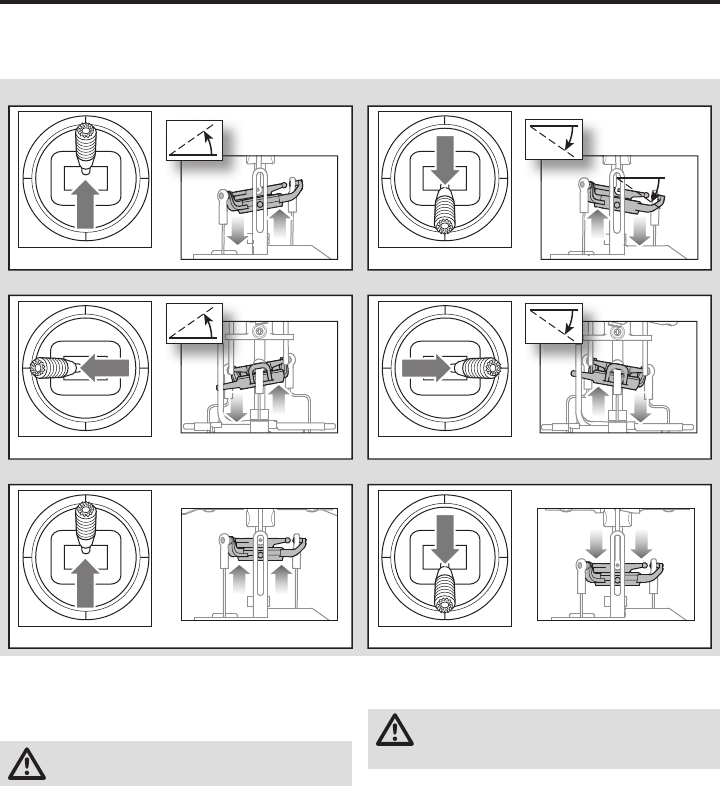
56
IT
Test di controllo della direzione
Accertarsi che l'interruttore Throttle Hold sia posizionato su
ON quando si effettuano i test di controllo della direzione.
Controllare i comandi prima del primo volo per accertarsi che i
servi, le aste di comando le altre parti funzionino correttamente.
Se i comandi non reagiscono come indicato nelle fi gure qui sot-
to, verifi care che la trasmittente sia programmata correttamente
prima di passare al test del motore.
Posizionare l'elicottero all'aperto su una superfi cie pulita, piana
(cemento o asfalto) e priva di ostacoli. Tenersi sempre a distanza
dalle pale del rotore in movimento.
ATTENZIONE: tenere gli animali lontano dall'elicottero.
Gli animali possono ferirsi se corrono verso l'elicottero.
1. Ambedue i motori emettono un triplice bip quando l'ESC
dell'elicottero si arma correttamente. Prima di continuare,
verifi care che lo stick del gas sia completamente abbassato.
2. Posizionare l'interruttore Throttle Hold su OFF.
AVVERTENZA: tenersi ad almeno 10 m di distanza
dall’elicottero quando il motore è in funzione. Non
tentare ancora di far volare l’elicottero.
3. Aumentare lentamente il gas fi nché le pale iniziano a girare.
Le pale principali devono girare in senso orario guardando
l'elicottero dall'alto. Le pale del rotore di coda devono girare
in senso antiorario guardando l'elicottero dal lato destro.
Elevatore
Elevatore in basso Elevatore in alto
Vista lato sinistro
Vista lato sinistro
Vista lato sinistro
Vista lato sinistro
Alettone
Passo collettivo
Alettone a sinistra
Passo collettivo in alto Passo collettivo in basso
Alettone a destra
Vista parte posteriore Vista parte posteriore
Motore
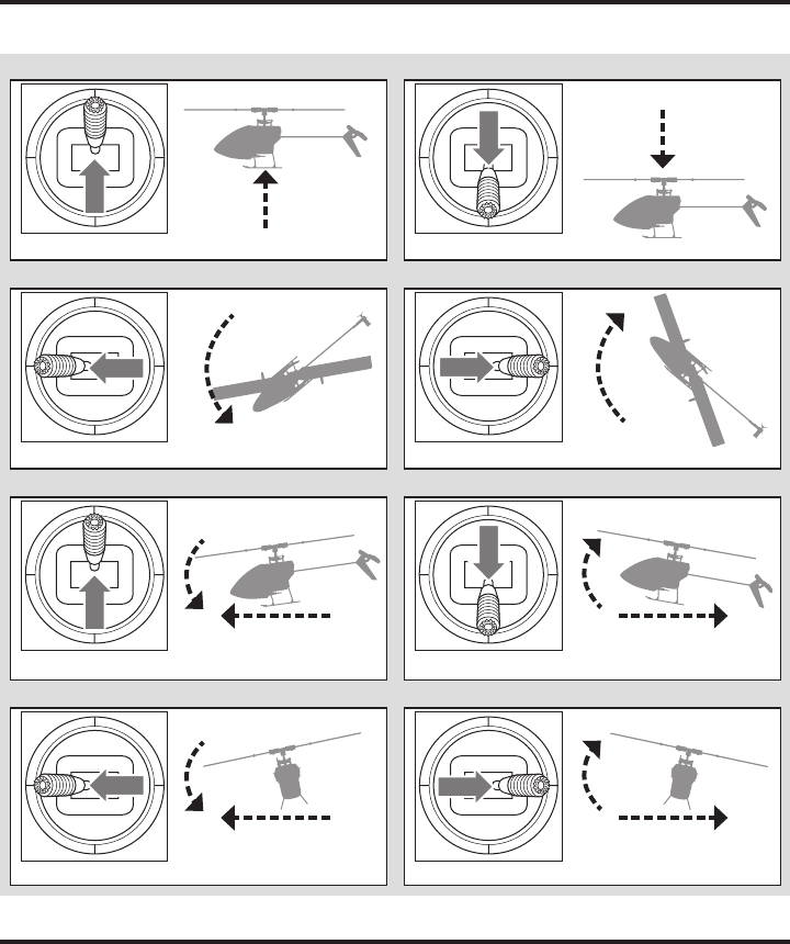
57 IT
In modalità Stabilità, l'elicottero vola in maniera analoga
ad un elicottero a passo fi sso (l'angolo di inclinazione è
limitato). Quando viene rilasciato lo stick del ciclico, il
modello si riporta in posizione livellata.
In modalità Intermedia, l'angolo di inclinazione non è limitato.
Quando viene rilasciato lo stick del ciclico, il modello non si ri-
porta in posizione livellata. La velocità del rotore è leggermen-
te inferiore e i comandi hanno una sensazione più "morbida".
Questa modalità è ideale per imparare il volo orizzontale e le
acrobazie di base quali stallo, virate e looping.
In modalità Agilità, l'angolo di inclinazione non è limitato.
Quando viene rilasciato lo stick del ciclico, il modello non si
riporta in posizione livellata. Inoltre, la velocità del rotore è
maggiore. Questa modalità è ideale per eseguire acrobazie
3D, come fl ip stazionari e tic toc.
Descrizione delle modalità di volo
Comandi di volo primari
Se non si ha dimestichezza con i comandi del Blade mCP S, si consiglia di dedicare un po' di tempo per acquisire familiarità
con il loro utilizzo prima di provare a volare.
Discesa
Imbardata a sinistra
Direzionale a sinistra
Gas in alto
Direzionale a destra
Gas in basso
Salita
Passo collettivo
Direzionale
Vista lato sinistro Vista lato sinistro
Avanti
Sinistra
Indietro
Destra
Elevatore avanti
Alettone a sinistra
Elevatore indietro
Alettone a destra
Elevatore
Alettone
Vista lato sinistro
Vista parte posteriore
Vista dall'alto
Vista parte posteriore
Vista dall'alto
Imbardata a destra
Vista lato sinistro

58
IT
Consultare le leggi e le normative locali prima
di scegliere un luogo dove far volare l'aeromodello.
Se questo è il primo elicottero a pitch collettivo, consigliamo di
chiedere assistenza ad un pilota di elicotteri esperto o ad un
aero club fi nché non si è in grado di pilotarlo in autonomia.
Si raccomanda di far volare l'aeromodello in ambienti esterni
con vento calmo o all'interno di una palestra di grandi dimen-
sioni. Evitare sempre di volare vicino a case, alberi, edifi ci e cavi.
Fare attenzione ad evitare anche le aree frequentate da molte
persone, come parchi affollati, cortili di scuole o campi sportivi.
È meglio decollare da superfi ci piane per consentire al modello
di avanzare senza rovesciarsi. Mantenere l'elicottero a circa 60
cm (2 piedi) dal suolo. Per facilitarne il controllo, durante i primi
voli la coda deve essere diretta verso il pilota. In modalità Sta-
bilità, rilasciando gli stick, il modello si livella autonomamente.
Attivando il pulsante Antipanico, l'elicottero si livella veloce-
mente. Se ci si trova disorientati mentre la modalità Stabilità è
attiva, abbassare lentamente lo stick della manetta per atterrare
dolcemente.
Durante i primi voli, tentare solo di effettuare manovre di decollo,
atterraggio e volo stazionario in un unico punto.
Decollo
IMPORTANTE: se il motore principale o il motore di coda
non si avviano correttamente quando si inizia ad accele-
rare, riportare immediatamente la manetta al minimo e
riprovare. Se il problema persiste, scollegare la batteria
di volo, verifi care la connessione nel gruppo ingranaggi
e assicurarsi che non vi siano cavi impigliati all'interno.
Posizionare il modello su una superfi cie piana e liscia,
libera da ostacoli e arretrare di circa 10 metri (30 piedi).
Accelerare lentamente fi nché il modello si trova a circa 60
cm (2 piedi) dal suolo, quindi verifi care il trim in modo che
voli correttamente. Una volta regolato il trim, iniziare a far
volare il modello.
Volo stazionario
Tramite piccole correzioni sulla trasmittente, cercare di tene-
re l'elicottero in un punto fi sso. Se il vento è calmo, il modello
non richiederà praticamente alcuna correzione. Dopo aver
mosso lo stick del ciclico e averlo riportato in posizione
centrale, il modello dovrebbe livellarsi da solo. Il modello
potrebbe continuare a muoversi per inerzia. Spostare lo stick
del ciclico nella direzione opposta per fermare il movimento.
Una volta acquisita una certa dimestichezza con il volo
stazionario, si può proseguire facendo spostare il modello in
luoghi diversi, mantenendo la coda sempre puntata verso di
sé. È inoltre possibile effettuare salite e discese usando lo
stick della manetta. Quando ci si sente più sicuri nell'effet-
tuare queste manovre, si può provare a volare con la coda in
posizioni diverse. È importante tenere sempre presente che
gli input dei comandi di volo ruotano insieme all'elicottero:
bisogna quindi cercare sempre di immaginare gli input dei
controlli relativi al naso dell'elicottero. Ad esempio, l'avanza-
mento in avanti farà sempre abbassare il naso dell'elicottero.
Il tempo di volo medio dell'elicottero utilizzando la batteria
raccomandata è di circa 4 minuti, a seconda di come si fa
volare l'aeromodello.
Spegnimento per bassa tensione (LVC)
La funzione LVC diminuisce la potenza dei motori quando
la tensione della batteria si abbassa. Quando la potenza del
motore diminuisce e il LED sull'ESC inizia a lampeggiare, è
necessario far atterrare immediatamente l'aeromodello e
ricaricare la batteria di volo.
La funzione LVC non previene lo scaricamento eccessivo
della batteria durante l'immagazzinamento/stoccaggio.
AVVISO: se la funzione LVC interviene ripetutamente, la
batteria potrebbe danneggiarsi.
Atterraggio
Per atterrare, abbassare lentamente la manetta tenendo il
modello in volo stazionario a bassa quota. Dopo l'atterraggio,
scollegare la batteria e rimuoverla dall'aeromodello per evitare
che si scarichi lentamente. Caricare completamente la batteria
prima di riporla. Durante l'immagazzinamento, controllare ogni
tanto che la tensione non scenda sotto i 3V per elemento.
Modalità Antipanico
In caso di diffi coltà mentre si pilota in qualsiasi modalità, tenere
premuto l'interruttore di connessione/Panic e portare gli stick
di comando in posizione neutra. La tecnologia SAFE riporterà
immediatamente l'aeromodello in assetto livellato, sempre che
si trovi ad una quota suffi ciente e non siano presenti ostacoli sul
suo percorso.
AVVISO: non attivare la modalità Antipanico se l'elicottero non si
trova ad una quota suffi ciente per recuperare l'assetto corretto.
Riportare lo stick del collettivo al 50% e rilasciare l'interruttore
di connessione/Panic per uscire dalla modalità Antipanico e
ritornare nella modalità di volo corrente.
AVVISO: prima di rilasciare l'interruttore di connessione/
Panic, accertarsi che lo stick del collettivo sia posizionato al
50%. Dopo aver rilasciato l'interruttore Panic, viene riattivata
la corsa negativa del collettivo, che potrebbe provocare una
discesa rapida del modello mCP S.
• La modalità Antipanico serve per offrire al pilota di acquisire
maggiore dimestichezza e permettergli di migliorare le
proprie abilità.
• Per un recupero rapido portare lo stick del collettivo al 50% e
gli altri comandi del trasmettitore in posizione neutra.
• Quando il modello ha raggiunto un assetto livellato, la corsa
negativa del collettivo viene ridotta per evitare che l'utente
causi la caduta a terra del modello.
In volo con il Blade mCP S

59 IT
Problema Possibile causa Soluzione
La risposta dell'elicottero
non è coerente o richiede
trim extra per neutralizzare
il movimento
L'aeromodello non è stato inizializ-
zato correttamente o una vibrazione
interferisce con il funzionamento
del sensore
Scollegare la batteria di volo, posizionare il trim di con-
trollo al centro e ripetere la procedura di inizializzazione
dell'elicottero
L'elicottero non risponde
alla manetta
La manetta è troppo alta e/o il trim
della manetta è troppo alto
Scollegare la batteria di volo, posizionare lo stick della
manetta nella posizione più bassa e abbassare il trim
della manetta di alcuni scatti. Collegare la batteria di volo
e consentire l'inizializzazione del modello
L'elicottero si è mosso durante
l'inizializzazione Scollegare la batteria di volo e ripetere l'operazione di inizializ-
zazione dell'elicottero evitando che l'elicottero si muova
Il tempo di volo dell'elicot-
tero è ridotto o l'elicottero
perde potenza
Batteria di volo quasi scarica Ricaricare completamente la batteria di volo
Batteria di volo danneggiata
Sostituire la batteria di volo e seguire le relative istruzioni
Le condizioni meteorologiche po-
trebbero presentare temperature
troppo basse
Verifi care che la batteria sia a temperatura ambiente
prima del volo
Il LED sulla scheda di con-
trollo del volo lampeggia
velocemente e l'aeromo-
dello non risponde alla
trasmittente (durante la
procedura di binding)
La trasmittente è troppo vicina
all'aeromodello durante la procedu-
ra di binding
Spegnere la trasmittente. Spostare la trasmittente portan-
dola a una distanza maggiore dall'aeromodello. Scollegare
e ricollegare la batteria di volo all'aeromodello. Seguire le
istruzioni per la procedura di binding
L'interruttore o il pulsante di con-
nessione non è stato tenuto premuto
mentre la trasmittente veniva accesa Spegnere la trasmittente e ripetere la procedura di binding
Aeromodello o trasmittente sono
troppo vicini a grossi oggetti metallici,
a una sorgente wireless o a un altro
trasmettitore
Spostare l'aeromodello e la trasmittente in un'altra posi-
zione e ripetere la procedura di binding
Guida alla risoluzione dei problemi
Controlli e manutenzione dopo il volo
Attacchi a
sfera
Verifi care che le sfere siano tenute saldamente, ma che non siano troppo strette. Se un attacco è troppo largo, potrebbe
staccarsi in volo e causare un incidente. Sostituire gli attacchi usurati prima che cedano.
Pulizia Accertarsi che la batteria non sia collegata prima di effettuare la pulizia. Rimuovere polvere e depositi con una spazzola
morbida o un panno asciutto che non lascia residui.
Cuscinetti Sostituire i cuscinetti se sono intaccati (non sono fl uidi quando girano) o se fanno resistenza in certi punti.
Cablaggio Accertarsi che i cavi non blocchino parti in movimento. Sostituire i cavi danneggiati e i connettori lenti.
Elementi di
fi ssaggio
Accertarsi che non vi siano viti, elementi di fi ssaggio o connettori allentati. Non stringere eccessivamente le viti di metallo
nei componenti di plastica. Serrare le viti in modo che le parti combacino perfettamente, quindi girare le viti solo 1/8 di
giro in più.
Rotori
Accertarsi che le pale dei rotori e altre parti che girano velocemente non presentino danni quali incrinature, sbavature,
scheggiature o graffi . Prima di volare, sostituire le parti danneggiate. Verifi care che ambedue le pale del rotore principale
abbiano lo stesso attrito sulle pinze portapale. Sollevando l’elicottero girato su un fi anco, le pale principali devono sop-
portare il proprio peso. Se l’elicottero viene agitato leggermente, le pale dovrebbero cadere.
Coda Verifi care che il rotore di coda non sia danneggiato e sostituirlo, se necessario. Verifi care se il tubo di coda è danneggiato
e sostituirlo, se necessario.
Parti
meccaniche
Controllare che il telaio principale e il carrello di atterraggio non siano danneggiati e sostituirli, se necessario. Verifi care
che il gioco tra gli ingranaggi sia corretto e che non vi siano inceppamenti nella rotazione a 360 gradi. Verifi care che tutti
i cavi non siano danneggiati e sostituirli, se necessario.

60
IT
Problema Possibile causa Soluzione
Il LED sulla scheda di con-
trollo del volo lampeggia
velocemente e l'elicottero
non risponde alla trasmit-
tente (dopo la procedura di
binding)
Attesa inferiore a 5 secondi tra la
prima accensione della trasmittente
e la connessione della batteria di
volo all'elicottero
Lasciare accesa la trasmittente. Scollegare e
ricollegare la batteria di volo all'elicottero
L'elicottero è collegato alla me-
moria di un modello diverso (solo
trasmittenti ModelMatch)
Selezionare la memoria modello corretta sulla trasmitten-
te. Scollegare e ricollegare la batteria di volo all'elicottero
Batteria di volo o batteria trasmit-
tente quasi scarica Sostituire o ricaricare le batterie
Aeromodello o trasmittente sono
troppo vicini a grossi oggetti metal-
lici, a una sorgente wireless o a un
altro trasmettitore
Spostare l'aeromodello e la trasmittente in un'altra
posizione e ripetere la procedura di connessione
L'elicottero vibra o trema
in volo Pale del rotore, alberino o portapale
danneggiati
Verifi care se pale del rotore principale e i portapale pre-
sentano incrinature o trucioli. Sostituire le parti danneg-
giate. Sostituire l'alberino piegato
Movimenti casuali
durante il volo Vibrazione
Assicurarsi che il ricevitore sia correttamente collegato all'e-
licottero. Ispezionare e bilanciare tutti i componenti rotanti.
Assicurarsi che l'albero principale e il rotore di coda non
siano danneggiati o piegati. Controllare se il meccanismo
presenta parti rotte o danneggiate e sostituire se necessario
Oscillazione/Agitazione
della coda o basse pre-
stazioni
Rotore di coda, tubo di coda, ingra-
naggi principali o albero principale
danneggiati, bulloni lenti, vibrazioni
Assicurarsi che il rotore di coda non presenti danni. Assicurarsi
che il tubo di coda e l'albero principale non presentino incrina-
ture. Controllare gli ingranaggi principali e accertarsi che non
ci siano inceppamenti che impediscono la rotazione completa.
Sostituire eventuali componenti danneggiati o usurati
Sbandamenti con vento
calmo Vibrazione, collegamenti danneg-
giati, servo danneggiato
Durante il normale funzionamento, i trim della trasmittente non
dovrebbero richiedere regolazioni e le posizioni centrali vengo-
no memorizzate durante la fase di inizializzazione. Se fossero
necessarie regolazioni dei trim dopo il decollo, verifi care l'equi-
librio di tutti i componenti rotanti, accertarsi che i collegamenti
non siano danneggiati e che i servo funzionino correttamente
Sbandamenti con vento Normale
Il modello sbanda con il vento, ma dovrebbe livellarsi in
volo. Mantenere lo stick del ciclico in posizione in modo
da far rimanere il modello stazionario. Il modello deve
inclinarsi con il vento per rimanere stazionario. Se il mo-
dello resta livellato, sbanderà con il vento
Attivare la modalità Anti-
panico o riportarlo a livello
non livellerà il modello
Il modello non è stato inizializzato
su una superfi cie piana e stabile Ripetere la procedura di inizializzazione del modello su
una superfi cie piana e stabile
Il modello non è stato fatto decollare
da una superfi cie piana Decollare sempre da una superfi cie piana
Elevata vibrazione
Albero principale incrinato Accertarsi che l'albero principale non presenti incrinature
e sostituire se necessario
I componenti rotanti non sono
bilanciati
Verifi care che l'albero principale, il rotore di coda, le pale del ro-
tore principale, il telaio principale e l'adattatore non presentano
danni e sostituire se necessario. Per funzionare correttamente,
la vibrazione deve essere minimizzata in modalità Antipanico
e di ripristino di livello Le vibrazioni devono essere ridotte al
minimo per garantire un corretto funzionamento delle funzioni
di "antipanico" e di ripristino del livellamento
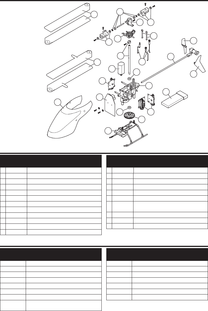
61 IT
Compo-
nente #
Descrizione
1 BLH3503 Motore principale con pignone
2 BLH3504 Pattino atterraggio e supporto batteria
3 BLH3505 Telaio principale con accessori
4 BLH3506 Ingranaggio principale
5 BLH3507 Albero principale con collare e accessori
6 BLH3508 Set rinvii con attacchi a sfera: 3 pezzi
7 BLH3509 Piatto ciclico di precisione completo
8 BLH3510
Pale rotore principale ad alte prestazioni con accessori
9 BLH3511
Pale rotore principali per volo veloce con accessori
10 BLH3512 Mozzo rotore principale con accessori
11 BLH3513
Alberino portapale con O-ring, boccola e accessori
12 BLH3514 Portapale principali con cuscinetti
Compo-
nente #
Descrizione
13 BLH3522 Set collegamenti testa rotore (8)
14 BLH3602 Gruppo coda completo
15 BLH3603 Rotore di coda
16 BLH5101 Unità di controllo Flybarless 3-in-1
17 BLH5103 Capottina rossa con aletta verticale
18 EFLH2215 Cuscinetto albero esterno 3x6x2 mm (2)
19
SPMSH2025L
2.0-Gram Performance servo
lineare lunga distanza, cavo 15 mm
20
EFLB2101S40
Batteria Li-Po 210 mAh 1S 3,7 V 40C
EFLC1013
Caricabatterie Li-Po USB 1S, 500 mAh
EFLRMLP6 MLP6DSM 6 canali SAFE Tx (Solo RTF)
Compo-
nente #
Descrizione
BLH3519 Capottina verde completa con aletta verticale
BLH3602L Gruppo coda completa lunga
BLH3603GR Rotore di coda verde (1)
BLH3603OR Rotore di coda arancione (1)
BLH3603YE Rotore di coda giallo (1)
EFLA7002UM
Cavo adattatore batteria ultra-micro corrente elevata 1s
EFLB2001S30 Batteria Li-Po 200 mAh 1S 3,7 V 30C
EFLC1004 Caricabatterie Li-Po CC Celectra 4 porte 1C
3,7 V 0,3 A
Compo-
nente #
Descrizione
EFLH3023 Set ingranaggi di formazione in fi bra di carbonio
SPM20000 Sistema DX20 20 canali con AR9020 M2
SPM6650 Sistema DX6e 6 canali con AR610 RX
SPM6750 Sistema DX6 MD2
SPMR1000 Solo trasmittente DXe
SPMR8000 Solo trasmittente DX8 MD2
SPMR9910 Solo trasmittente nera DX9 MD2
Elenco delle parti
Parti opzionali
8
9
1
11
10
13
12
12
5
7
19
16
20
18
3
18
17
2
4
17
14
15
6
19
Vista esplosa

62
IT
Garanzia
Periodo di garanzia
Garanzia esclusiva - Horizon Hobby, LLC (Horizon) garantisce che
il prodotto acquistato (il “Prodotto”) sarà privo di difetti relativi ai
materiali e di eventuali errori di montaggio alla data di acquisto. Il
periodo di garanzia è conforme alle disposizioni legali del paese
nel quale il prodotto è stato acquistato. Tale periodo di garanzia
ammonta a 6 mesi e si estende ad altri 18 mesi dopo tale termine.
Limiti della garanzia
(a) La garanzia è limitata all’acquirente originale (Acquirente) e
non è cedibile a terzi. L’acquirente ha il diritto a far riparare o a
far sostituire la merce durante il periodo di questa garanzia. La
garanzia copre solo quei prodotti acquistati presso un rivenditore
autorizzato Horizon. Altre transazioni di terze parti non sono cop-
erte da questa garanzia. La prova di acquisto è necessaria per
far valere il diritto di garanzia. Inoltre, Horizon si riserva il diritto di
cambiare o modificare i termini di questa garanzia senza alcun
preavviso e di escludere tutte le altre garanzie già esistenti.
(b) Horizon non si assume alcuna garanzia per la dis-
ponibilità del prodotto, per l’adeguatezza o l’idoneità del
prodotto a particolari previsti dall’utente. È sola responsabilità
dell’acquirente il fatto di verificare se il prodotto è adatto agli
scopi da lui previsti.
(c) Richiesta dell’acquirente – spetta soltanto a Horizon, a
propria discrezione riparare o sostituire qualsiasi prodotto
considerato difettoso e che rientra nei termini di garanzia.
Queste sono le uniche rivalse a cui l’acquirente si può appel-
lare, se un prodotto è difettoso.
Horizon si riserva il diritto di controllare qualsiasi componente
utilizzato che viene coinvolto nella rivalsa di garanzia. Le
decisioni relative alla sostituzione o alla riparazione sono a
discrezione di Horizon. Questa garanzia non copre dei danni
superficiali o danni per cause di forza maggiore, uso errato del
prodotto, un utilizzo che viola qualsiasi legge, regolamentazione
o disposizione applicabile, negligenza, uso ai fini commerciali, o
una qualsiasi modifica a qualsiasi parte del prodotto.
Questa garanzia non copre danni dovuti ad un’installazione
errata, ad un funzionamento errato, ad una manutenzione
o un tentativo di riparazione non idonei a cura di soggetti
diversi da Horizon. La restituzione del prodotto a cura
dell’acquirente, o da un suo rappresentante, deve essere
approvata per iscritto dalla Horizon.
Limiti di danno
Horizon non si riterrà responsabile per danni speciali, diretti, indi-
retti o consequenziali; perdita di profitto o di produzione; perdita
commerciale connessa al prodotto, indipendentemente dal fatto
che la richiesta si basa su un contratto o sulla garanzia. Inoltre la
responsabilità di Horizon non supera mai in nessun caso il prez-
zo di acquisto del prodotto per il quale si chiede la responsabilità.
Horizon non ha alcun controllo sul montaggio, sull’utilizzo o sulla
manutenzione del prodotto o di combinazioni di vari prodotti.
Quindi Horizon non accetta nessuna responsabilità per danni o
lesioni derivanti da tali circostanze. Con l’utilizzo e il montaggio
del prodotto l’utente acconsente a tutte le condizioni, limitazioni e
riserve di garanzia citate in questa sede.
Qualora l’utente non fosse pronto ad assumersi tale respon-
sabilità associata all’uso del prodotto, si suggerisce di restituire il
prodotto intatto, mai usato e immediatamente presso il venditore.
Indicazioni di sicurezza
Questo è un prodotto sofisticato di hobbistica e non è un gio-
cattolo. Esso deve essere manipolato con cautela, con giudizio
e richiede delle conoscenze basilari di meccanica e delle
facoltà mentali di base. Se il prodotto non verrà manipolato in
maniera sicura e responsabile potrebbero risultare delle lesioni,
dei gravi danni a persone, al prodotto o all’ambiente circostan-
te. Questo prodotto non è concepito per essere usato dai bam-
bini senza una diretta supervisione di un adulto. Il manuale del
prodotto contiene le istruzioni di sicurezza, di funzionamento e
di manutenzione del prodotto stesso. È fondamentale leggere
e seguire tutte le istruzioni e le avvertenze nel manuale prima
di mettere in funzione il prodotto. Solo così si eviterà un utilizzo
errato e si preverranno incidenti, lesioni o danni.
Domande, assistenza e riparazioni
Il vostro negozio locale e/o luogo di acquisto non possono
fornire garanzie di assistenza o riparazione senza previo col-
loquio con Horizon. Questo vale anche per le riparazioni in
garanzia. Quindi in tale casi bisogna interpellare un rivenditore,
che si metterà in contatto subito con Horizon per prendere una
decisione che vi possa aiutare nel più breve tempo possibile.
Manutenzione e riparazione
Se il prodotto deve essere ispezionato o riparato, si prega di
rivolgersi ad un rivenditore specializzato o direttamente ad
Horizon. Il prodotto deve essere imballato con cura. Bisogna far
notare che i box originali solitamente non sono adatti per effet-
tuare una spedizione senza subire alcun danno. Bisogna effet-
tuare una spedizione via corriere che fornisce una tracciabilità
e un’assicurazione, in quanto Horizon non si assume alcuna
responsabilità in relazione alla spedizione del prodotto. Inserire
il prodotto in una busta assieme ad una descrizione dettagliata
degli errori e ad una lista di tutti i singoli componenti spediti.
Inoltre abbiamo bisogno di un indirizzo completo, di un numero di
telefono per chiedere ulteriori domande e di un indirizzo e-mail.
Garanzia e riparazione
Le richieste in garanzia verranno elaborate solo se è presente
una prova d’acquisto in originale proveniente da un riven-
ditore specializzato autorizzato, nella quale è ben visibile la
data di acquisto. Se la garanzia viene confermata, allora il
prodotto verrà riparato o sostituito. Questa decisione spetta
esclusivamente a Horizon Hobby.
Riparazioni a pagamento
Se bisogna effettuare una riparazione a pagamento, effet-
tueremo un preventivo che verrà inoltrato al vostro riven-
ditore. La riparazione verrà effettuata dopo l’autorizzazione
da parte del vostro rivenditore. La somma per la riparazione
dovrà essere pagata al vostro rivenditore. Le riparazioni a
pagamento avranno un costo minimo di 30 minuti di lavoro
e in fattura includeranno le spese di restituzione. Qualsiasi
riparazione non pagata e non richiesta entro 90 giorni verrà
considerata abbandonata e verrà gestita di conseguenza.
ATTENZIONE: Le riparazioni a pagamento sono dis-
ponibili solo sull’elettronica e sui motori. Le riparaz-
ioni a livello meccanico, soprattutto per gli elicotteri
e le vetture RC, sono molto costose e devono essere
effettuate autonomamente dall’acquirente. 10/15
63 IT
Informazioni sulla conformità per l’Unione Europea
Dichiarazione di Conformità EU:
Horizon Hobby, LLCcon la presente dichiara che il prodotto è conforme ai requisiti essenziali e ad altre
disposizioni rilevanti delle direttive RED e EMC.
Una copia della dichiarazione di conformità per l’Unione Europea è disponibile a:
http://www.horizonhobby.com/content/support-render-compliance.
Istruzioni del RAEE per lo smaltimento da parte di utenti dell’Unione Europea
Questo prodotto non deve essere smaltito
assieme ai rifi uti domestici. Al contrario,
l’utente è responsabile dello smaltimento di tali
rifi uti che devono essere portati in un centro
di raccolta designato per il riciclaggio di rifi uti
elettrici e apparecchiature elettroniche. La
raccolta differenziata e il riciclaggio di tali rifi uti
provenienti da apparecchiature nel momento dello smaltimen-
to aiuteranno a preservare le risorse naturali e garantiranno
un riciclaggio adatto a proteggere il benessere dell’uomo e
dell’ambiente. Per maggiori informazioni sui centri di raccolta,
contattare il proprio uffi cio locale, il servizio di smaltimento
rifi uti o il negozio presso il quale è stato acquistato il prodotto.
Garanzia e Assistenza - Informazioni per i contatti
Stato di acquisto Horizon Hobby Telefono/Indirizzo e-mail Indirizzo
Unione
Europea
Horizon Technischer Service service@horizonhobby.eu Hanskampring 9
D 22885 Barsbüttel, Germany
Sales: Horizon Hobby GmbH +49 (0) 4121 2655 100

64
IT
©2017 Horizon Hobby, LLC.
Blade, E-fl ite, Bind-N-Fly, BNF, the BNF logo, DSM, DSM2, DSMX, AS3X, SAFE, the SAFE logo and ModelMatch
are trademarks or registered trademarks of Horizon Hobby, LLC.
The Spektrum trademark is used with permission of Bachmann Industries, Inc.
Futaba is a registered trademark of Futaba Denshi Kogyo Kabushiki Kaisha Corporation of Japan
All other trademarks, service marks and logos are property of their respective owners.
Patents pending.
Created 6/17 55415 BLH5100/BLH5150