Horizon Hobby DASRX15 Receiver User Manual 56737 BLH Fusion 270 MULTI indb
Horizon Hobby, LLC Receiver 56737 BLH Fusion 270 MULTI indb
UserManual.wiki
>
Horizon Hobby
>
DASRX15 User Manual
>
Users Manual
Contents
1.
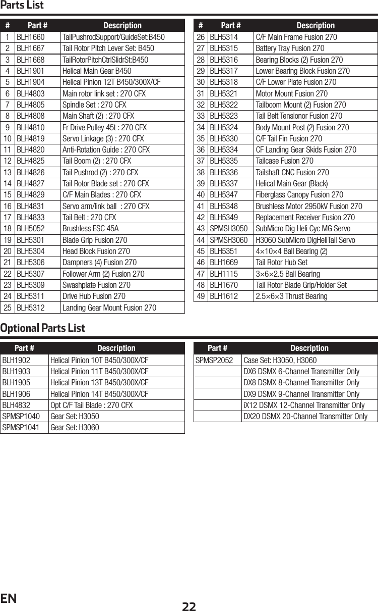
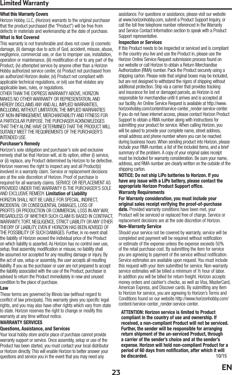
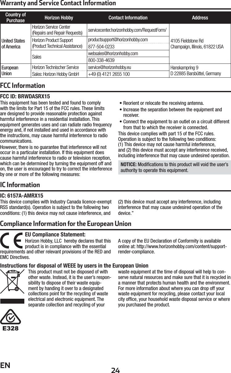
User Manual
2.
Users Manual
Users Manual
Navigation menu
Upload a User Manual
Namespaces
Wiki Guide
HTML
PDF
Info
Views
User Manual
Discussion / Help
Navigation