Horizon Hobby DASRX15 Receiver User Manual 56737 BLH Fusion 270 MULTI indb
Horizon Hobby, LLC Receiver 56737 BLH Fusion 270 MULTI indb
Contents
- 1. User Manual
- 2. Users Manual
Users Manual

Instruction Manual
Bedienungsanleitung
Manuel d’utilisation
Manuale di Istruzioni
®
™
2
EN
WARNING AGAINST COUNTERFEIT PRODUCTS: If you ever need to replace a Spektrum™ component found in
a Horizon Hobby product, always purchase from Horizon Hobby, LLC or a Horizon Hobby authorized dealer to
ensure authentic high-quality Spektrum™ product. Horizon Hobby, LLC disclaims all support and warranty with regards,
but not limited to, compatibility and performance of counterfeit products or products claiming compatibility with DSM
or Spektrum™ technology.
• Always keep a safe distance in all directions around
your model to avoid collisions or injury. This model is
controlled by a radio signal subject to interference from
many sources outside your control. Interference can
cause momentary loss of control.
• Always operate your model in open spaces away from
full-size vehicles, traffi c and people.
• Always carefully follow the directions and warnings
for this and any optional support equipment (chargers,
rechargeable battery packs, etc.).
• Always keep all chemicals, small parts and anything
electrical out of the reach of children.
• Always avoid water exposure to all equipment not
specifi cally designed and protected for this purpose.
Moisture causes damage to electronics.
• Never place any portion of the model in your mouth as it
could cause serious injury or even death.
• Never operate your model with low transmitter batteries.
• Always keep aircraft in sight and under control.
• Always move the throttle fully down at rotor strike.
• Always use fully charged batteries.
• Always keep transmitter powered on while aircraft is
powered.
• Always remove batteries before disassembly.
• Always keep moving parts clean.
• Always keep parts dry.
• Always let parts cool after use before touching.
• Always remove batteries after use.
• Never operate aircraft with damaged wiring.
• Never touch moving parts.
Age Recommendation: Not for children under 14 years. This is not a toy.
WARNING: Read the ENTIRE instruction manual to become familiar with the features of the product before
operating. Failure to operate the product correctly can result in damage to the product, personal property and
cause serious injury.
This is a sophisticated hobby product. It must be operated with caution and common sense and requires some basic
mechanical ability. Failure to operate this Product in a safe and responsible manner could result in injury or damage
to the product or other property. This product is not intended for use by children without direct adult supervision. Do
not use with incompatible components or alter this product in any way outside of the instructions provided by Horizon
Hobby, LLC. This manual contains instructions for safety, operation and maintenance. It is essential to read and follow
all the instructions and warnings in the manual, prior to assembly, setup or use, in order to operate correctly and avoid
damage or serious injury.
The following terms are used throughout the product literature to indicate various levels of potential harm when
operating this product:
WARNING: Procedures, which if not properly followed, create the probability of property damage, collateral damage,
and serious injury OR create a high probability of superfi cial injury.
CAUTION: Procedures, which if not properly followed, create the probability of physical property damage AND a
possibility of serious injury.
NOTICE: Procedures, which if not properly followed, create a possibility of physical property damage AND a little or no
possibility of injury.
NOTICE
All instructions, warranties and other collateral documents are subject to change at the sole discretion of Horizon
Hobby, LLC. For up-to-date product literature, visit horizonhobby.com and click on the support tab for this product.
Meaning of Special Language
Safety Precautions and Warnings
3EN
Components ARF BNF Basic
Airframe
Blade® Fusion 270 Included Included
Motors
BL Motor 2950kV, Fusion 270 (BLH5348) Installed Installed
Receiver
Replacement Receiver, Fusion 270 (BLH5349) Required Installed
ESC
Brushless ESC 45A (BLH5052 ) Installed Installed
Swash Servos
Sub-Micro Digital Heli Cyclic MG Servo (SPMSH3050) Required Installed
Tail Servo
Sub-Micro Digital Heli Tail MG Servo (SPMSH3060) Required Installed
Battery Thrust 14.8V 1300mAh 35C 4S Battery (EFLRB13004S35) Required Required
Charger Li-Po Balancing Charger Required Required
Transmitter Full Range DSM2®/DSMX® technology transmitter Required Required
Table of Contents
Box Contents ....................................................................3
First Flight Preparation ......................................................4
Flying Checklist ................................................................4
Low Voltage Cutoff (LVC) ...................................................4
Electronic Speed Controller Governor Operation ...............4
Transmitter Setup (Bind-N-Fly® Basic) ..............................5
Installing the Flight Battery ...............................................7
Transmitter and Receiver Binding (Bind-N-Fly® Basic) .......7
Throttle Hold .....................................................................8
Control Tests .....................................................................8
Pre-Flight Checklist ..........................................................9
Flying the Blade Fusion 270 .............................................9
Gyro Gain Adjustment .....................................................10
Tail Belt Tension .............................................................10
Post-Flight Inspections and Maintenance ........................10
Servo Adjustment (AR636A only) .....................................13
Trim Flight (AR636A only) ................................................14
Calibration Procedure (AR636A only) ...............................15
Almost-Ready-to-Fly Assembly .......................................16
Optional AR7210BX Setup (ARF version) ..........................18
Troubleshooting Guide ....................................................19
Exploded View ................................................................20
Parts List ........................................................................22
Optional Parts List ...........................................................22
Limited Warranty ............................................................23
Warranty and Service Contact Information ......................24
FCC Information ..............................................................24
IC Information .................................................................24
Compliance Information for the European Union ..............24
• Blade® Fusion™ 270 helicopter
Length 560mm
Height 190mm
Flying Weight 626 g
Main Rotor Diameter 620mm
Tail Rotor Diameter 160mm
To receive product updates, special offers and more, register your product at www.horizonhobby.com
Box Contents
Specifi cations

4
EN
First Flight Preparation
• Remove and inspect contents
• Begin charging the fl ight battery (not included)
• Install the electronics (ARF version)
• Confi gure the fl ight controller (ARF version)
• Install the fl ight battery in the helicopter
(once it has been fully charged)
• Program your computer transmitter
• Bind your transmitter
• Familiarize yourself with the controls
• Find a suitable area for fl ying
Flying Checklist
❏Always turn the transmitter on fi rst
❏Plug the fl ight battery into the lead from the ESC
❏Allow the ESC to initialize and arm properly
❏ Verify control directions and gyro compensations are correct
❏Fly the model
❏Land the model
❏Unplug the fl ight battery from the ESC
❏Always turn the transmitter off last
Low Voltage Cuto (LVC)
The ESC will continuously lower power to the motor until
complete shutdown when the battery reaches 12V under
load. This helps prevent over-discharge of the Li-Po battery.
Land immediately when the ESC activates LVC. Continuing
to fl y after LVC can damage the battery, cause a crash or
both. Crash damage and battery damaged due to over-
discharge are not covered under warranty.
Repeatedly fl ying the helicopter until LVC activates will
damage the helicopter battery.
Disconnect and remove the Li-Po battery from the aircraft
after use to prevent trickle discharge. During storage, make
sure the battery charge does not fall below 3V per cell.
The included electronic speed controller (ESC) utilizes a
head speed governor to maintain a constant head speed
during fl ight. The governor will work to maintain a constant
head speed throughout maneuvers and the discharge cycle
of the fl ight battery.
The throttle position determines the requested head speed,
and although throttle curves are still used, they will be a
constant value; all positions of the curve are set to the same
value. The lowest position of the normal fl ight mode throttle
curve must be set to 0 to ensure the motor can be disabled.
The default throttle curve settings listed in the transmitter
setup tables should be acceptable to most pilots and
we recommend starting with these values. If you feel
an adjustment is necessary after a few fl ights, adjust
the throttle percentage for the desired fl ight mode. We
recommend making small changes of 5% to fi nd your
preferred head speed.
Remember the throttle position on the transmitter is simply
requesting a specifi c head speed and this is not related to
the actual motor power percentage.
Electronic Speed Controller Governor Operation
5EN
Transmitter Setup (Bind-N-Fly® Basic)
Program your transmitter before attempting to bind or fl y
the helicopter. Always start by creating a new model in the
transmitter to ensure no existing settings are inadvertently
used. Transmitter programming values are shown below for the
Spektrum
™
Transmitters. The fi les for models using Spektrum
™
transmitters with Spektrum
™
AirWare
™
software are also
available for download online at www.spektrumrc.com.
Panic Mode Operation
Ele D/R Switch: Pos 0 = Panic Mode Off
Pos 1 = Panic Mode On
D/R & Expo
Channel Sw Pos D/R Expo
AILE 0 100 0
1850
ELEV 0 100 0
1850
RUDD 0 100 0
1850
Timer
Down Timer 4:00
Switch THR CUT
ADJUST LISTSETUP LIST
DX6i
Throttle Curve
Switch Pos (F Mode) Pos 1 Pos 2 Pos 3 Pos 4 Pos 5
NORM 0 50 50 50 50
STUNT* 65 65 65 65 65
Mix 1
GYRO > GYRO ACT
RATE D+125% U+125%
SW ELE D/R TRIM-INH
TRAVEL ADJ
Channel Travel
THRO 100/100
AILE 100/100
ELEV 100/100
RUDD 100/100
GYRO 100/100
PITC 100/100
Reverse
Channel Direction
THRO N
AILE N
ELEV N
RUDD N
GYRO N
PITC N
GYRO
RATE SW-F.MODE
Switch Pos (F Mode)
0 82% NORM 0
1 75% STUNT 1
Modulation Type
AUTO DSMX-ENABLE
D/R COMBI
D/R SW AILE
Model Type HELI
Swash Type 1 servo 90
Pitch Curve
Switch Pos (F Mode) Pos 1 Pos 2 Pos 3 Pos 4 Pos 5
NORM 25 37 50 75 100
STUNT 0 25 50 75 100
HOLD 25 37 50 75 100
6
EN
* Function is not available on
all transmitters
Panic Mode Operation
Switch I
Press = Panic Mode On
Release = Panic Mode Off
Throttle Curve
Sw Pos
(B) Pt 1 Pt 2 Pt 3 Pt 4 Pt 5
N 0 45 45 45 45
16565656565
27575757575
Hold 0 0 0 0 0
Pitch Curve
Sw Pos
(B) Pt 1 Pt 2 Pt 3 Pt 4 Pt 5
N 25 37 50 75 100
1 0 25 50 75 100
2 0 25 50 75 100
HOLD 25 37 50 75 100
Channel Travel Reverse
THR 100/100 Normal
AIL 100/100 Normal
ELE 100/100 Normal
RUD 100/100 Normal
GER 100/100 Normal
Channel Travel Reverse
PIT 100/100 Normal
AX2* 100/100 Normal
AX3* 100/100 Normal
AX4* 100/100 Normal
Servo Setup
FUNCTION LIST
DX6G2, DX6e, DX7G2, DX8G2, DX9, iX12, DX18, DX20
Timer
Mode Count Down
Time 5:00
Start Throttle Out
Over 5%
One Time Inhibit
Model Type HELI
Swash Type Normal
F-Mode Setup
Switch 1 Switch B
Switch 2 Inhibit
Hold Switch Switch H
01
Channel Assign
Channel Input Confi g
1 Throttle
2 Aileron
3 Elevator
4 Rudder
5 Gear INH
6 Collective
7 AUX 2*
Frame Rate
11ms*
DSMX
SYSTEM SETUP
Gyro
Normal 85%
Stunt 1 78%
Stunt 2 65%
Hold 85%
Channel Gear
Switch Flight Mode
Mixing
P-Mix 1 Normal
Channels Ger > Gyr
Rate 125%/0%
Offset –100%
Switch Switch I
Position 0 1
D/R & Expo
Chan Sw (F) Pos D/R Expo
AILE
0 100/100 0
1 85/85 0
2 85/85 0
ELEV
0 100/100 0
1 85/85 0
2 85/85 0
Rudd
0 100/100 0
1 85/85 0
2 85/85 0
7EN
1. Lower the throttle.
2. Power on the transmitter.
3. Center all trims.
4. To allow the ESC to arm and to keep rotors from initiat-
ing at startup, turn on throttle hold and normal fl ight
mode before connecting the fl ight battery.
5. Attach hook material to the helicopter frame and loop
material to the battery.
6. Install the fl ight battery on the helicopter frame. Secure
the fl ight battery with a hook and loop strap. Connect
the battery cable to the ESC.
CAUTION: Make sure the fl ight battery, wire and
connector does not come into contact with the
motor. Failure to do so will cause the motor, ESC and
battery to overheat, resulting in a crash causing property
damage and injury.
7. Do not move the helicopter until the AR636A initializes.
The swashplate will center, indicating that the unit
is ready. The AR636A status LED will illuminate once
initialization has been completed
8. The helicopter motor will emit 5 ascending tones,
indicating the ESC is armed.
CAUTION: Always disconnect the Li-Po battery
from the ESC power lead when not fl ying to avoid
over-discharging the battery. Batteries discharged to a
voltage lower than the lowest approved voltage may
become damaged, resulting in loss of performance and
potential fi re when batteries are charged.
Binding Procedure
1. Program your transmitter using the Transmitter Setup found in this manual.
2. Insert the bind plug in the BND/DAT port on the receiver.
3. Connect the fl ight battery to the ESC. The orange LED on the AR636 will begin fl ashing rapidly to indicate bind mode.
4. Move the throttle stick to the low throttle position in normal mode.
5. Follow the procedures of your specifi c transmitter to enter Bind Mode. The system will connect within a few seconds.
Once connected, the orange LED will turn off and the AR636A will start the initialization process.
6. When the initialization process is complete, the Status LED light will come on solid orange.
7. Disconnect the fl ight battery and remove the bind plug from the AR636A. Store the bind plug in a convenient place.
Transmitter and Receiver Binding (Bind-N-Fly® Basic)
Binding is the process of programming the receiver to recognize the GUID (Globally Unique Identifi er) code of a single
specifi c transmitter. You need to ‘bind’ your chosen Spektrum™ DSM2/DSMX technology equipped aircraft transmitter to
the receiver for proper operation.
WARNING: You must move the throttle to the LOW/OFF position during binding. Failure to do so may cause the
rotor blades to spin and the helicopter to lift during the AR636A initialization, which could result in damage to
property and injury.
NOTICE: Remove the bind plug to prevent the system from entering bind mode the next time the power is turned on.
CAUTION: When using a Futaba® transmitter with a Spektrum™ DSM2® module, you must reverse the throttle channel
If you encounter problems, obey binding instructions and refer to transmitter troubleshooting guide for other instructions.
If needed, contact the appropriate Horizon Product Support offi ce.
Installing the Flight Battery
8
EN
Throttle Hold
Control Tests
Throttle hold is used to prevent the motor from powering on
inadvertently. For safety, turn throttle hold ON any time you
need to touch the helicopter or check the direction controls.
Throttle hold is also used to turn off the motor quickly if the
helicopter is out of control, in danger of crashing, or both.
The blades will continue to spin briefl y when throttle hold is
activated. Pitch and direction control is still maintained.
CAUTION: You must complete the Tail Rotor and Cyclic tests prior to every fl ight. Failure to complete the tests
and ensuring the sensor corrects in the proper direction can cause the helicopter to crash, resulting in property
damage and injury.
Tail Rotor
1. Power on the transmitter.
2. Turn TH HOLD ON and put transmitter in normal mode.
3. Connect the fl ight battery to the ESC.
NOTICE: Do not allow the helicopter to move until the
Status LED is solid orange. The AR636A will not operate
correctly if the helicopter moves before the Status LED is
solid orange.
4. Move the rudder
stick to the right. The
pitch slider on the tail
shaft should move
toward the tail case.
If the pitch slider
moves in the oppo-
site direction, ensure
the rudder channel
reverse setting within the transmitter is set to normal.
5. Release the rudder control. Manually turn the helicopter
nose to the left. The fl ight controller should compensate
by moving the tail slider towards the tail case.
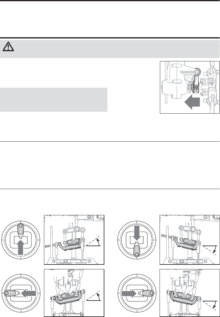
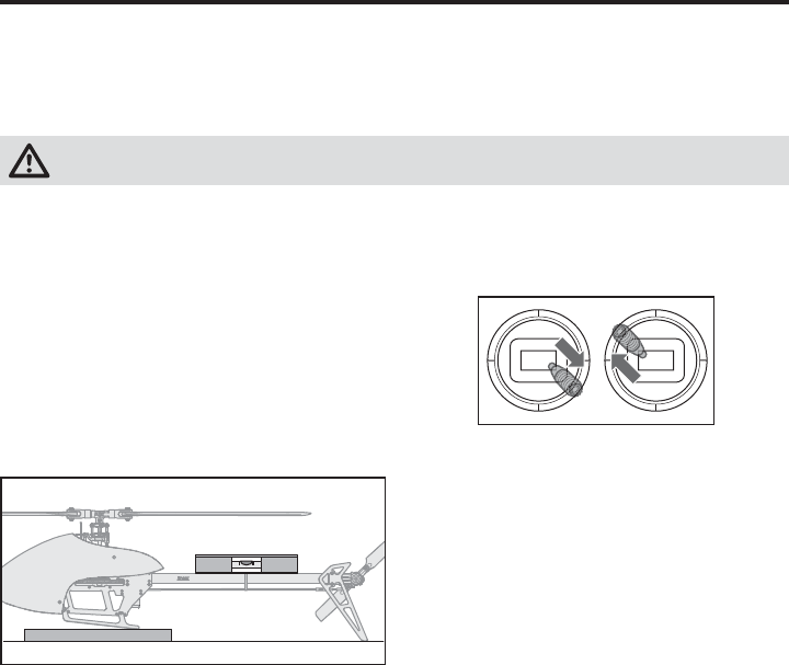
Cyclic and Collective Control Test
Ensure the throttle hold is ON when performing the direction control tests. Test the controls prior to each fl ight to
ensure the servos, linkages and parts operate correctly. If the controls do not react as shown in the illustrations below,
confi rm the transmitter is programmed correctly before continuing on to the Motor test.
Elevator
Aileron Rear View
Left Side View Left Side View
Rear View
Elevator down Elevator up
Aileron left Aileron right
Cyclic
When using a fl ybarless fl ight controller, you are controlling
rotational rates while the AR636A controls the servos. You
are not directly controlling the servos with the transmitter.
It is normal for the swashplate to slowly move back to
its original position after a stick input and for the servos
to not move at the same speed as your control sticks.
1. Tilt the helicopter forward. The swashplate must
tilt backward.
2. Roll the helicopter left. The swashplate must roll right.
9EN
Motor Test
Place the helicopter outdoors on a clean, fl at and level
surface (concrete or asphalt) free of obstructions. Always
stay clear of moving rotor blades.
1. Before you continue, confi rm that TH HOLD is ON. The
motor will emit 5 ascending tones after the helicopter’s
ESC has armed properly.
WARNING: The motor will spin when the throttle
is increased while TH HOLD is OFF.
WARNING: Stay at least 30 feet (10 meters) away
from the helicopter when the motor is running. Do
not attempt to fl y the helicopter at this time.
2. Ensure the throttle is lowered completely. Confi rm
the transmitter is still set to normal fl ight mode. Turn
throttle hold OFF to enable throttle control. Slowly
increase the throttle until the blades begin to spin. The
main blades spin clockwise when viewing the helicopter
from the top. The tail rotor blades spin counterclockwise
when viewing the helicopter from the right-hand side.
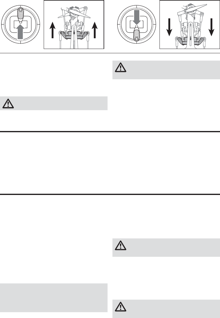
Collective Pitch Front View Front View
Collective pitch up Collective pitch down
Pre-Flight Checklist
❏Check all screws and ensure that they are tight
❏Check belt tension and ensure that it is not too tight or
too loose
❏Check main and tail blades to ensure they are not damaged
❏Check all links and make sure they move freely but do
not pop off easily
❏Check that the transmitter and fl ight batteries are fully
charged
❏Check all wires to ensure that they are not cut, pinched,
or chaffed and are properly secured
❏Check all wire connections
❏Check gears and make sure no teeth are missing
❏Make sure fl ight battery is properly secured
❏Make sure the receiver is properly secured
❏Perform a complete control test
❏Verify the fl ight controller is correcting in the proper directions
❏Check that servos are functioning properly
Consult local laws and ordinances before choosing a location to fl y your aircraft.
Select a large, open area away from people and objects.
Your fi rst fl ights should be outdoors in low-wind conditions.
Always stay at least 30 feet (10 meters) away from the
helicopter when it is fl ying.
The Blade Fusion 270 is intended to be fl own outdoors by
experienced pilots
Panic Recovery
If you get into distress while fl ying in any mode, push and
hold the Panic Switch and move the control sticks to their
neutral position. SAFE® technology will immediately return
the aircraft to an upright level attitude, if the aircraft is at
a suffi cient height with no obstacles in its path. Return the
collective stick to 50% and release the Panic Switch to turn
off Panic Recovery and return to the current fl ight mode.
NOTICE: Before releasing the panic switch, make
sure the collective stick has been returned to the 50%
position. Once the panic switch has been released, full
negative collective becomes available, which could
cause the helicopter to descend rapidly.
• This mode is intended to provide the pilot with the
confi dence to continue to improve their fl ight skills.
• Move the collective stick to 50% and return all other
transmitter controls to neutral for the quickest recovery.
• When panic is activated and once the model has reached a
level upright attitude, the negative collective is reduced to
prevent the user from pushing the model into the ground.
Takeoff
Deliberately increase throttle and establish a hover
at least 24” (0.6 meter) high, outside of ground effect.
CAUTION: Making large inputs to the roll or pitch
controls while the helicopter is on the ground
may result in a crash.
Flying
The helicopter lifts off the ground when the rotor head
reaches a suitable speed. Establish a low-level hover to
verify proper operation of your helicopter.
First fl ights should be performed in normal mode and low
cyclic and rudder dual rates until you are familiar with the
fl ying manner of the Blade Fusion 270.
CAUTION: Always fl y the helicopter with your
back to the sun and the wind to prevent loss of
fl ight control.
Flying the Blade Fusion 270
10
EN
Landing
Establish a low level hover. Deliberately lower the throttle
until the helicopter lands.
When the helicopter is in stunt mode:
• The rotor head speed is constant.
• The main rotor will increase negative pitch as the
throttle/collective stick is moved from the middle stick
position to the low stick position. Negative pitch allows
the helicopter to fl y upside down and perform aerobatics.
Change between stunt and idle up modes in a hover with
the throttle near the hovering stick position.
WARNING: Do not use wooden main blades with
the Blade Fusion 270 or injury and/or property
damage could occur. Only use Blade Fusion 270
replacement carbon fi ber main blades.
Gyro Gain Adjustment
• If the tail wags or oscillates, lower the gain on the gyro.
In the transmitter gyro menu, decrease the gyro gain
values a small amount at a time until the helicopter is
stable within a particular fl ight mode.
• If the tail is drifting while hovering, increase the gain on the gyro.
In the transmitter gyro menu, increase the gyro gain
values a small amount at a time until the tail starts to
wag/oscillate. Afterwards, reduce the gain until the tail
stops wagging/oscillating within a particular fl ight mode.
Tail Belt Tension
Belt tension that is too tight results in loss of power and causes the belt to wear more quickly. Tension that is too loose
can cause belt damage and loss of tail rotor control in fl ight.
To check for proper belt tension:
1. View the tail rotor drive belt through the opening at the
back of the main frame.
2. Use a hex wrench or standard screwdriver to compress the
belt through the opening.
3. Apply light pressure on the belt, compressing the belt
toward the left side of the tail boom.
4. The belt tension is correct if the compressed side of
the belt reaches approximately halfway to the opposite
side of the belt.
a. If the compressed side of the belt reaches farther
than halfway to the other side of the belt, the tension
is too loose.
b. If the compressed side of the belt does not reach
halfway to the other side of the belt, the tension is
too tight.
To adjust belt tension:
1. Loosen the two horizontal stabilizer screws.
2. Loosen the 2 screws at the back of the main frame.
3. Slide the boom forward or aft to adjust the belt tension.
4. When the belt tension is properly adjusted, tighten the
2 screws at the back of the frame.
5. Tighten the horizontal stabilizer screws.
Post-Flight Inspections and Maintenance
Ball Links
Make sure the plastic ball link holds the control ball, but is not tight (binding) on the ball. When a link
is too loose on the ball, it can separate from the ball during fl ight and cause a crash. Replace worn
ball links before they fail.
Cleaning Make sure the battery is not connected before cleaning. Remove dust and debris with a soft brush
or a dry lint free cloth.
Bearings Replace bearings when they become damaged.
Wiring Make sure wiring does not block moving parts. Replace damaged wiring and loose connectors.
Fasteners Make sure there are no loose screws, other fasteners or connectors. Do not over tighten metal screws
in plastic parts. Tighten screw so parts are mated together, then turn screw only 1/8th of a turn more.
Rotors Make sure there is no damage to rotor blades and other parts which move at high speed. Damage
to these parts includes cracks, burrs, chips or scratches. Replace damaged parts before fl ying.
Flight Controller Make sure the AR636A is securely attached to the frame. Replace the double-sided tape when
necessary. The helicopter will crash if the AR636A separates from the helicopter frame.
11 EN
The Fusion 270 default settings are appropriate for most users. We recommend fl ying with the default parameters before
making any adjustments.
WARNING: Always disconnect the motor wires from the ESC before performing the following steps.
After completing the adjustments, reconnect the motor wires to the ESC before attempting to fl y the model.
Advanced Settings (AR636A only)
Gain Parameters
1. Cyclic P Gain Adjustment (Default 100%)
Higher gain will result in greater stability. Setting the gain
too high may result in random twitches if your model has
an excessive level of vibration. High frequency oscillations
may also occur if the gain is set too high.
Lower gain will result in less stability. Too low of a value may
result in a less stable model particularly outdoors in winds.
If you are located at a higher altitude or in a warmer climate,
higher gains may be benefi cial—the opposite is true for
lower altitude or colder climates.
2. Cyclic I Gain Adjustment (Default 100%)
Higher gain will result in the model remaining still, but may
cause low frequency oscillations if increased too far.
Lower gain will result in the model drifting slowly.
If you are located at a higher altitude or in a warmer climate,
higher gains may be benefi cial—the opposite is true for
lower altitude or colder climates.
3. Cyclic D Gain Adjustment (Default 100%)
Higher gain will improve the response rate of your inputs.
If the gain is raised too much, high frequency oscillations
may occur.
Lower gain will slow down the response to inputs.
4. Cyclic Response (Default 100%)
Higher cyclic response will result in a more aggressive
cyclic response.
Lower cyclic response will result in a less aggressive cyclic
response.
5. Tailrotor P Gain Adjustment (Default 100%)
Higher gain will result in greater stability. Setting the gain
too high may result in random twitches if your model has
an excessive level of vibration. High frequency oscillations
may also occur if the gain is set too high.
Lower gain may result in a decrease in stability. Too low
of a value may result in a less stable model particularly
outdoors in winds.
If you are located at a higher altitude or in a warmer climate,
higher gains may be benefi cial—the opposite is true for
lower altitude or colder climates.
6. Tailrotor I Gain Adjustment (Default 100%)
Higher gain results in the tail remaining still. If the gain is
raised too far, low speed oscillations may occur.
Lower gain will result in the tail drifting in fl ight over time.
If you are located at a higher altitude or in a warmer climate,
higher gains may be benefi cial—the opposite is true for
lower altitude or colder climates.
7. Tailrotor D Gain Adjustment (Default 100%)
Higher gain will improve the response rate to your inputs. If
raised too far, high frequency oscillations may occur.
Lower gain will slow down the response to inputs, but will
not have an effect on stability.
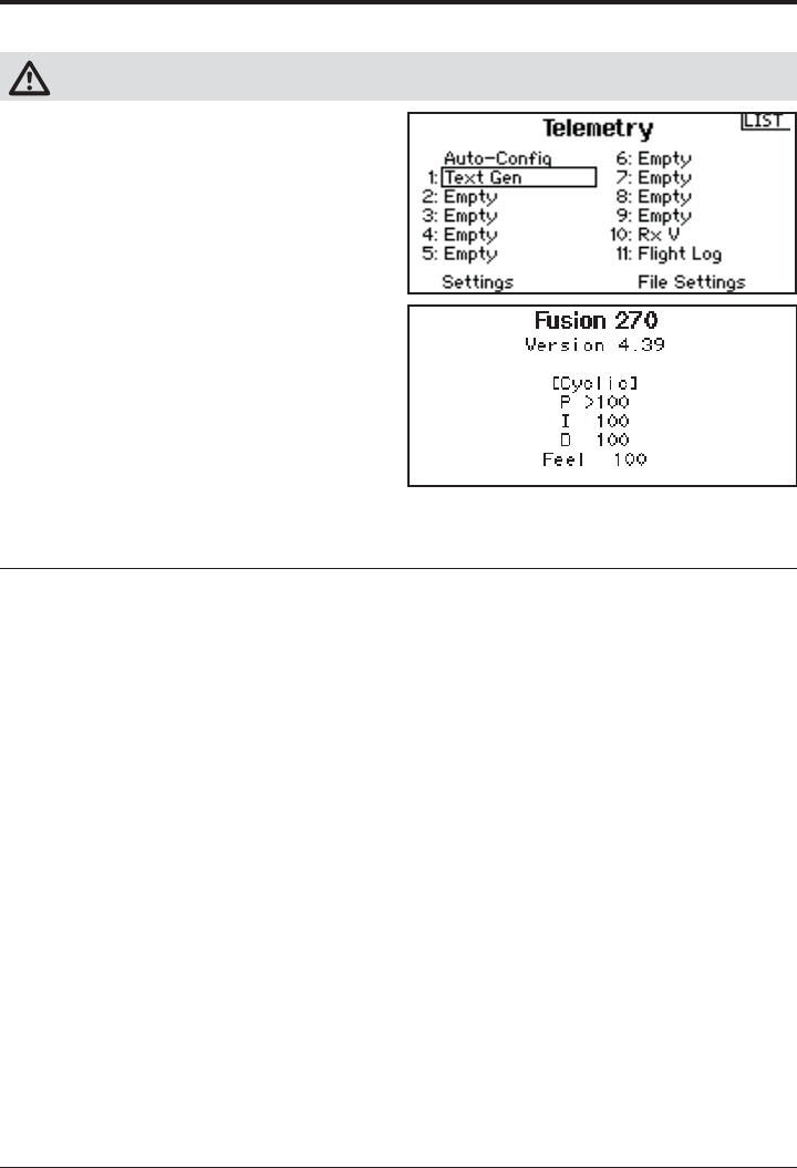
Telemetry Based Text Generator for Advanced Settings
Advanced parameters may be easily read in text form
when using a Spektrum™ telemetry based transmitter.
Transmitters may require a fi rmware update to access this
function. To register and update Spektrum™ transmitters,
visit www.spektrumrc.com.
Turning On Text Gen
Access the Telemetry menu, select one of the “Empty”
Telemetry slots and scroll to select “Text Gen.” Set the
display option to active (Act). Once the Text Gen message
feature has been enabled, the transmitter will display text
based menus on the telemetry screens for adjusting PID
values and servo center points. The helicopter must be
bound and initialized for the Text Gen screen to function;
scroll from the home screen past the telemetry screen(s)
to access the Text Gen screen.
Using Text Gen
The available features and stick inputs used to manipulate
the menus are the same as the methods outlined in the
following section, but using the text based programming is
more intuitive. Refer to the transmitter manual for details
on how to utilize telemetry menus.
12
EN
Once you have entered Gain Adjustment Mode, you can
move the cyclic stick forward and backward to select the
gain parameter you would like to adjust. Moving the stick
backward will select the next parameter. Moving the stick
forward will select the previous parameter.
The selected gain parameter is indicated on the Flight Log
screen and by the lean of the swashplate on the roll axis.
The current gain value for the selected parameter is indicated on the Flight
Log screen and by the angle of the swashplate (forward or backward) as
shown in the table at the right.
Move the cyclic stick left or right to adjust the gain value. Moving the stick right
will increase the gain value. Moving the stick left will decrease the gain value.
It is always best to adjust one gain at a time. Make small adjustments
(5% or less) and test fl y the model to evaluate the adjustments that were made.
If you would like to reset the current gain value to the default value of 100%, move and hold the rudder stick
full right for 1 second. The swash will level on the pitch axis, indicating a 100% gain setting.
Saving the Gain Adjustments
All Spektrum™ Transmitters:
1. Lower the throttle stick to the lowest position and
release the sticks.
2. Activate the panic recovery function until the swash
servos move.
3. Deactivate the panic recovery function to save the gain
adjustments.
4. Reconnect the main drive motor to the ESC. Your model
is now ready for fl ight.
Entering Gain Adjustment Mode (AR636A only)
Adjusting the Gain Values
If you are using a Spektrum™ telemetry-enabled transmitter, the gain adjustments can be viewed on the Flight Log
screen. Refer to your transmitter instructions to locate this screen. The gain parameter currently selected will fl ash on the
transmitter screen. If you are not using a Spektrum™ telemetry-enabled transmitter, the parameter and gain values are
indicated by the position of the swashplate on the helicopter.
P age number
1 = Cyclic gains
2 = Tail rotor gains
Gain parameter
selected
Gain value
display location
Flight Log Screen
Spektrum™ Transmitters:
1. Lower the throttle stick to the lowest position.
2. Power ON the transmitter.
3. Install the fl ight battery on the helicopter frame, securing
it with the hook and loop strap.
4. Connect the battery connector to the ESC.
5. Place the helicopter on a fl at surface and leave it still
until the orange receiver LED glows solid, indicating
initialization is complete.
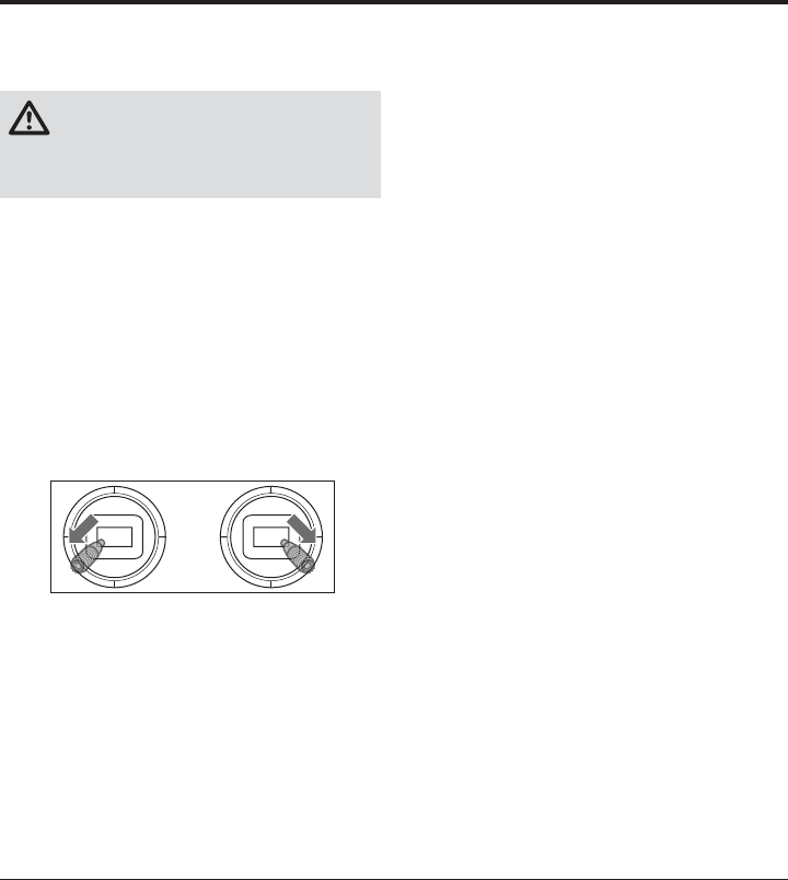
6. Move and hold both transmitter sticks to the bottom right
corner as shown.
7. Activate the panice recovery function switch until the
swash servos move.
8. Release the sticks and deactivate panic recovery. The
model is now in Gain Adjustment Mode.
9. Proceed to Adjusting the Gain Values to make any
desired changes.
Parameter # Display location Swash Position Page #
1 A 100% to the Left 1
2 B 50% to the Left 1
3 L 25% to the Left 1
4 R Swashplate Level 1
5 A 25% to the Right 2
6 B 50% to the Right 2
7 L 100% to the Right 2
Swash Position Gain Value
Full backward 0%
50% backward 50%
Level forward and backward 100%
50% forward 150%
Full forward 200%
13 EN
Servo Adjustment (AR636A only)
Your Blade Fusion 270 helicopter was setup at the factory
and test fl own. The servo adjustment steps are usually only
necessary in special circumstances, such as after a crash
or if a servo or linkage is replaced.
WARNING: To ensure your safety, always
disconnect the motor wires from the ESC before
performing the following steps. After you have
completed the adjustments, reconnect the motor wires
to the ESC before attempting to fl y the model.
All Spektrum™ Transmitters:
1. Lower the throttle stick to the lowest position.
2. Power ON the transmitter.
3. Install the fl ight battery on the helicopter frame,
securing it with the hook and loop strap.
4. Connect the battery connector to the ESC.
5. Place the helicopter on a fl at surface and leave it still
until the orange receiver LED glows solid, indicating
initialization is complete.
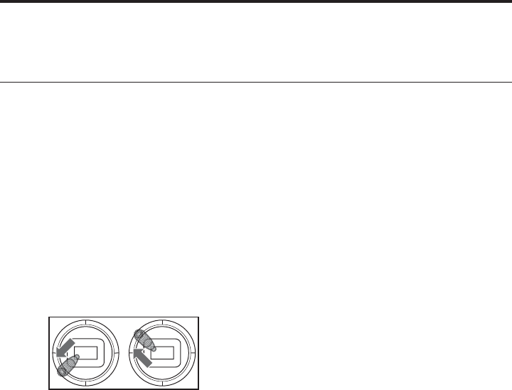
6. Hold the left stick to the bottom left corner and the
right stick to the bottom right corner as shown.
7. Activate the panic recovery function until the swash
servos move.
8. Release the sticks and deactivate the panic recovery
function. The model is now in Servo Adjustment Mode.
9. Proceed to Adjusting the Servo Neutral Position to
make any desired changes.
Adjusting the Servo Neutral Position
With the model in Servo Adjustment Mode, the control stick
and gyro inputs are disabled and the servos are held in the
neutral position. Check the position of the servo arms to
see if they are perpendicular to the servos.
• If the arms are perpendicular to the servos, no
adjustment is necessary. Exit Servo Adjustment Mode.
• If one or more servo arm is not perpendicular to the
servos, continue the servo adjustment process.
While watching the swashplate servos, apply backward
cyclic and release. One of the servos will jump, indicating
which servo is selected. Press backward cyclic and release
until the servo that needs to be adjusted is selected.
Once the servo you wish to adjust is selected, move the
cyclic stick right or left to adjust the servo neutral position
in the desired direction.
If you would like to reset the current servo to the default
neutral position, hold the rudder stick full right for 1second.
The range of adjustment is limited. If you are unable to
adjust the servo arm to be perpendicular to the servo, you
must reset the servo to the default neutral position, remove
the servo arm and place it back onto the servo as close to
perpendicular as possible. You may then adjust the servo
neutral position using the left/right cyclic stick.
Swashplate Leveling
Before saving your adjustments and exiting servo
adjustment mode, verify the swashplate is level and both
main rotor blades are at 0 degrees.
If they are not, make linkage adjustments as necessary.
Saving the Servo Adjustments
All Spektrum™ Transmitters:
1. Lower the throttle stick to the lowest position and
release the sticks.
2. Activate Panic Recovery until the swash servos move.
3. Deactivate Panic Recovery to save the servo
adjustments.
4. Reconnect the main drive motor to the ESC. Your model
is now ready for fl ight.
All of the settings are stored internally, so your adjustments
will be maintained each time you initialize the model.
14
EN
Trim Flight (AR636A only)
Entering Trim Flight Mode
1. Lower the throttle stick to the lowest position.
2. Center all trims. For the included Spektrum™ DXe
transmitter (RTF only), the trims are centered when
you hear a higher pitched beep while pressing the
trim button. Move the trim in both directions until you
hear the high-pitched beep.
3. Power ON the transmitter.
4. Install the fl ight battery in the helicopter.
5. Connect the battery connector to the ESC.
6. Place the helicopter on a fl at surface and leave it still
until the motor beeps twice and the blue ESC LED
glows solid, indicating initialization is complete.
7. Place the helicopter where you are going to take off.
8. Move and hold the left stick to the bottom left corner
and the right stick to the top left corner as shown.
9. Activate Panic Recovery until the
swashplate rotates around once.
10. Release the sticks and deactivate panic recovery.
11. The model is ready for the trim fl ight.
Performing the Trim Flight
1. Slowly increase the throttle to lift the model into a
stationary hover. Make corrections as necessary to
keep the model still. Evaluation does not begin until the
throttle stick is over 50% and the sticks are centered.
Making corrections will not affect the result but a
longer fl ight may be necessary.
2. Keep the model stationary in a hover for a total of 30
seconds. Sliding and slow movements are okay. The
main goal is to keep the rotor disk level.
3. Once you are satisfi ed with the trim fl ight, land the model.
Exiting Trim Flight Mode
1. After landing, lower the throttle stick to the lowest position.
2. Activate Panic Recovery for 2 seconds, or until the
swashplate twitches, indicating the servo positions
and attitude values have been recorded and trim fl ight
mode has been exited.
Flight Test
After performing the trim fl ight, test-fl y the model to
evaluate the leveling characteristics.
• The model should return to level fl ight consistently.
• During takeoff, the model should lift off with minimal
corrections.
• During a hover, the control stick should remain close to
center. Small corrections are acceptable.
If the model performs poorly or does not level properly
after the trim fl ight, retry the entire trim fl ight procedure.
If the problem persists, inspect the model for damaged
components, a bent shaft or anything that may result in
increased vibration. The trim fl ight may not record the
correct values due to excessive vibration, fl ying in wind
or the model not staying level. In these cases, shorter
trim fl ights may be necessary. Try the 30-second, level
trim fl ight without corrections mentioned above fi rst. If
the leveling characteristics are not satisfactory, gradually
shorten the trim fl ights, checking for improvements until
the model performs as described.
Perform this procedure if the model is not performing well or has been recently rebuilt from a crash.
The trim fl ight procedure was performed during the factory test fl ight and only needs to be performed if you notice the
model is not returning to level consistently or if the model does not remain still during stationary pirouettes. The trim fl ight
is used to determine the optimal settings for SAFE® technology during fl ight.
The trim fl ight must be performed in calm conditions.
15 EN
If the helicopter is experiencing drift issues after completing the trim fl ight procedure located at www.bladehelis.com,
perform the following calibration. The calibration procedure may also be needed following crash repairs.
To perform the calibration procedure below, the Spektrum™ AR636 receiver installed in the Blade Fusion 270 must have
the most recent fi rmware. Receiver fi rmware updates and instructions are available under “PC Firmware Updates” at
www.spektrumrc.com/technology/AS3X.aspx. The transmitter/receiver programming cable (SPMA3065) is required to
update the receiver fi rmware.
WARNING: Before beginning the calibration procedure, disconnect the main motor and tail motor leads to
prevent accidental motor startup during calibration.
To perform the calibration procedure:
1. Ensure the surface used for calibration is level.
2. Power on the transmitter and helicopter, allowing
them to initialize.
3. Turn Throttle Hold ON.
4. Ensure the main motor and tail motor leads
are disconnected. Set the fl ight mode switch to
Intermediate Mode (FM1).
5. Using a bubble level as shown below, level the
helicopter by placing a foam blade holder under the
landing skid. Use additional items, as necessary, to
build up under the landing skid until the tail boom is
level.
6. Hold the left stick to the bottom right corner, the
right stick to the upper left corner and activate the
Panic Recovery function until the LED on the receiver
fl ashes once.
7. Release both sticks and deactivate Panic Recovery.
8. The LED on the receiver will remain solid for
1-2minutes while the calibration takes place.
Do not move the helicopter until the calibration
is completed. If the LED begins blinking rapidly, an
error has occurred. Begin the calibration procedure
again, starting with step 1.
9. After the calibration is successfully completed,
the receiver LED will blink slowly (2 seconds on,
2seconds off).
10. Power the helicopter off.
11. Reconnect the main motor and tail motor wires.
12. Perform the trim fl ight procedure as shown in the
Advanced Settings Addendum available at www.
bladehelis.com.
13. During subsequent fl ights after the trim fl ight, the
helicopter should return to within 5 degrees of level
consistently.
Bubble level
Foam blade holder
Calibration Procedure (AR636A only)
16
EN
Almost-Ready-to-Fly Assembly
1. Begin assembly by removing the gyro plate from
the rear of the frame.
2. Center the three swash servos and install the servo
arms and linkage balls as shown.
3. Mount the cyclic servos to the bearing blocks as
shown.
4. Install the swashplate linkages. Adjust the length
of the linkages so the swashplate is level and the
marks on top of the head block line up with the
corresponding marks on the blade grips when the
servos are centered.
3X
17 EN
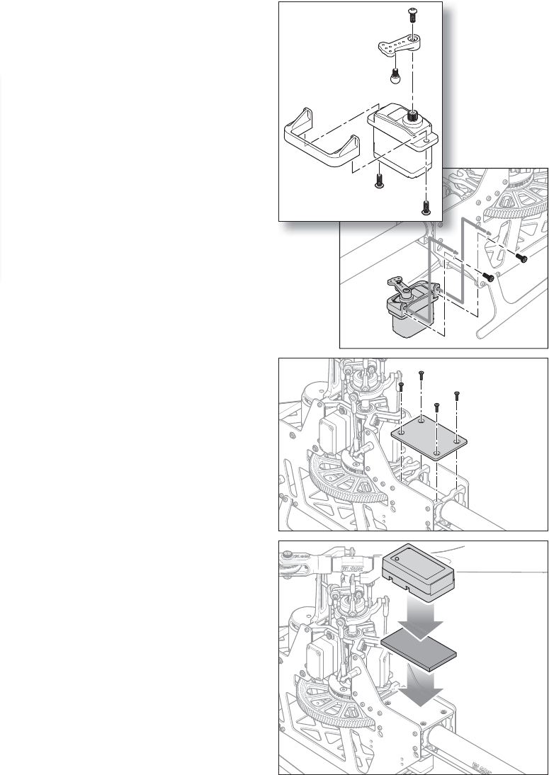
5. Attach the tail servo mount to the tail servo.
6. Center the tail servo and attach the servo arm to
the servo. Attach the ball end to the servo arm.
7. Mount the tail servo assembly to the inside of the
right frame side, as shown.
8. Connect the tail pushrod to the tail servo ball end.
9. Route the servo wires through the tail boom
mounts and under the gyro plate. Ensure the
wires stay well clear of all rotating parts.
At any point where the servo wires pass through
or cross the frame plates, use sandpaper to round
the edge of the frame plate to prevent the wires
from chafi ng. Use zip ties to secure the wires to
the frame.
10. Re-attach the gyro plate to the frame.
11. Mount the fl ight controller to the gyro plate using
double sided foam tape provided with your fl ight
controller.
12. Review the instructions provided with your fl ight
controller to complete the servo connections and
setup.
18
EN
Swashplate Cyclic Gain: Centered
Swashplate Direct Feed Forward: Centered
Tail Dynamic: Centered
Remote Gyro Gain
Normal 65%
Stunt 1 55%
Stunt 2 50%
Hold 65%
Optional AR7210BX Setup (ARF version)
The following table provides the settings for the Spektrum™ AR7210BX DSMX® Flybarless Control System when used in
conjunction with Spektrum™ H3050 and H3060 digital servos.
NOTICE: Always follow the manual included with the fl ight controller to perform a Factory Reset of the AR7210BX prior
to beginning a new model setup.
Complete the Control Tests section to verify the controls are responding correctly prior to attempting fl ight.
PARAMETER MENU
(Menu-LED is fl ashing quickly) OFF Purple
Flashing Purple
Solid Red Flashing Red
Solid Blue
Flashing Blue
Solid
A Cyclic and rudder trim/SAFE® trim
Use aileron and elevator stick to trim, hold button 2s to trim rudder. Reset all by rudder stick input.
Switch trim mode by activating SAFE® technology using the SAFE® switch channel.
B Control Behavior transmitter
CSwashplate – Pitching up behavior medium*
DTail – Rate Consistency medium*
E Stick deadband small*
FTail – RevoMIX off*
G Cyclic response normal*
H Pitch boost off*
I RPM Governor – Throttle response slightly increased
J RPM Governor – Initial spool up rate
200 RPM/s
K RPM Governor – Quick change rate
500 RPM/s
SETUP MENU
(Menu-LED is steady ON ) OFF Purple
Flashing Purple
Solid Red
Flashing Red
Solid Blue
Flashing Blue
Solid Red/
Blue
A Mounting orientation
horizontal
socket, back
BSwashplate –
servo frequency 200 Hz
CRudder –
center position pulse length
1520 μs*
DRudder – servo frequency 333 Hz
ERudder – servo endpoints
Use rudder stick to move servo to right endpoint and wait, then left endpoint and wait (or vice versa)
FRudder – sensor direction reversed
GSwashplate –
servo centering reference
position CH1 center
position CH2 center
position
CH3 center
position
HSwashplate – mixer 120°*
ISwashplate –
servo directions nor | nor |
nor
JSwashplate –
cyclic pitch geometry
Use aileron stick to adjust 6° cyclic pitch on the roll axis to one direction (blades aligned with fuselage)
KCollective pitch range &
endpoints
Set collective stick to max/min position and use aileron stick to adjust desired pitch.
Set pitch direction by rudder stick input: Status-LED blue = positive pitch, red = negative pitch
LSwashplate – cyclic limit
Move aileron, elevator and throttle stick. Adjust maximum limit by rudder stick input
MSwashplate –
sensor directions nor | nor*
NRPM Governor –
Operation mode
deactivated*
*Factory setting

19 EN
Troubleshooting Guide
Problem Possible Cause Solution
Helicopter will not
bind to the transmitter
(during binding AR636A only)
Low ight battery or transmitter
battery voltage Fully charge or replace the ight battery and/or transmitter batteries
AR636A is not in bind mode Make sure the bind plug is connected to the AR636A BND/DAT port
Transmitter is not in bind mode Power on the transmitter while holding the Trainer/Bind switch.
Hold the Trainer/Bind switch until binding is complete
Transmitter too close to the
helicopter during binding process
Power off the transmitter. Move the transmitter further away from
the helicopter.
Disconnect and reconnect the ight battery to the helicopter and
follow binding instructions
Helicopter will not
link to the transmitter
(after binding)
Helicopter is bound to
a different model memory
(ModelMatch™ radios only)
Disconnect the ight battery. Select the correct model memory on
the transmitter. Reconnect the ight battery
Flight battery/Transmitter battery
charge is too low Replace or recharge batteries
AR636A will not initialize
The helicopter was moved during
initialization Lay the helicopter on its side during initialization if windy
The transmitter is powered off Power on the transmitter
Controls are not centered Center elevator, aileron and rudder controls. Make sure the
throttle is at idle
Helicopter will not respond
to the throttle but responds
to other controls
Throttle not at idle and/or throttle
trim is too high Lower the throttle stick and lower the throttle trim
The transmitter is not in normal mode
or throttle hold is on
Make sure the transmitter is in normal mode and throttle hold is off
The motor is not connected to the
ESC or the motor wires are damaged
Connect the motor wires to the ESC and check
motor wires for damage
Flight battery charge is too low Replace or recharge ight battery
Throttle channel is reversed Reverse the throttle channel on the transmitter
Helicopter power is lacking
Flight battery has low voltage Fully charge the ight battery
Flight battery is old or damaged Replace the ight battery
Flight battery cells are unbalanced Fully charge the ight battery, allowing the charger
time to balance the cells
Excessive current is being drawn
through the BEC Check all servos and the helicopter motor for damage
Tail drive belt tension is not correct See "Tail Belt Tension" in this manual
Helicopter will not lift off
Main rotor head is not spinning in the
correct direction
Make sure the main rotor head is spinning clockwise.
Refer to the motor control test
Transmitter settings are not correct Check throttle and pitch curve settings and pitch control direction
Flight battery has low voltage Fully charge the ight battery
Main rotor blades are installed
backwards
Install the main rotor blades with the thicker side as the leading edge
The helicopter tail spins out
of control
Rudder control and/or sensor
direction reversed
Make sure the rudder control and the rudder sensor are operating
in the correct direction
Tail servo is damaged Check the rudder servo for damage and replace if necessary
Inadequate control arm throw Check the rudder control arm for adequate travel
and adjust if necessary
Tail belt is too loose Make sure the tail drive belt tension is adjusted correctly
The helicopter wobbles
in ight
Cyclic gain is too high Please review the “Advanced Settings - Gain Adjustments” section
Headspeed is too low Increase the helicopter's head speed via your transmitter settings
and/or using a freshly charged ight pack
Dampers are worn Replace the main rotor head dampers
20
EN
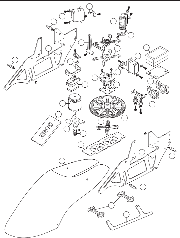
Exploded View
26
34
34
26
33
39
42
43
44
43
43
34
34
36
32
40
41
5
29
30
25
28
9
16
16
16
11
16
24
27
31
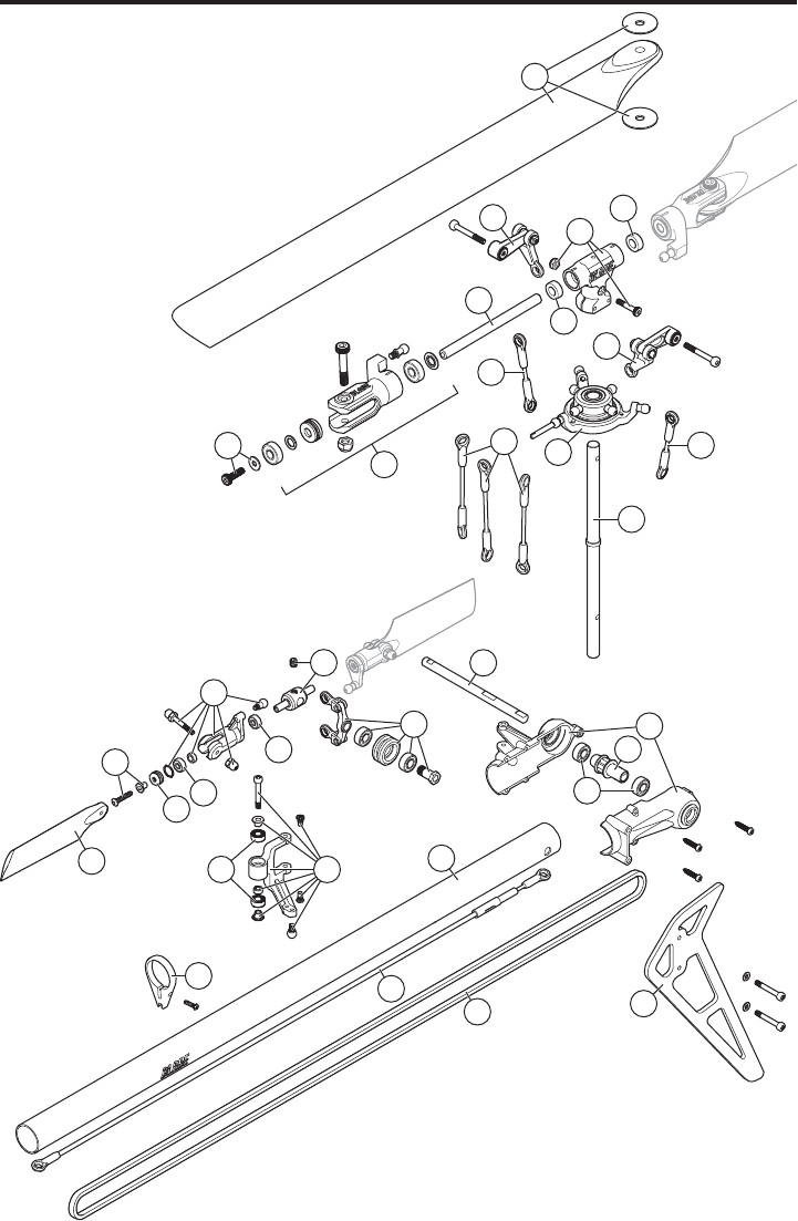
21 EN
212
1
38
48
47
47
47
49
46
14
46
3
38
45
37
13
17 35
19
6
6
22
22
21
20
7
7
21
8
10 23
15

22
EN
# Part # Description
1 BLH1660 TailPushrodSupport/GuideSet:B450
2 BLH1667 Tail Rotor Pitch Lever Set: B450
3 BLH1668 TailRotorPitchCtrlSlidrSt:B450
4 BLH1901 Helical Main Gear B450
5 BLH1904 Helical Pinion 12T B450/300X/CF
6 BLH4803 Main rotor link set : 270 CFX
7 BLH4805 Spindle Set : 270 CFX
8 BLH4808 Main Shaft (2) : 270 CFX
9 BLH4810 Fr Drive Pulley 45t : 270 CFX
10 BLH4819 Servo Linkage (3) : 270 CFX
11 BLH4820 Anti-Rotation Guide : 270 CFX
12 BLH4825 Tail Boom (2) : 270 CFX
13 BLH4826 Tail Pushrod (2) : 270 CFX
14 BLH4827 Tail Rotor Blade set : 270 CFX
15 BLH4829 C/F Main Blades : 270 CFX
16 BLH4831 Servo arm/link ball : 270 CFX
17 BLH4833 Tail Belt : 270 CFX
18 BLH5052 Brushless ESC 45A
19 BLH5301 Blade Grip Fusion 270
20 BLH5304 Head Block Fusion 270
21 BLH5306 Dampners (4) Fusion 270
22 BLH5307 Follower Arm (2) Fusion 270
23 BLH5309 Swashplate Fusion 270
24 BLH5311 Drive Hub Fusion 270
25 BLH5312 Landing Gear Mount Fusion 270
# Part # Description
26 BLH5314 C/F Main Frame Fusion 270
27 BLH5315 Battery Tray Fusion 270
28 BLH5316 Bearing Blocks (2) Fusion 270
29 BLH5317 Lower Bearing Block Fusion 270
30 BLH5318 C/F Lower Plate Fusion 270
31 BLH5321 Motor Mount Fusion 270
32 BLH5322 Tailboom Mount (2) Fusion 270
33 BLH5323 Tail Belt Tensionor Fusion 270
34 BLH5324 Body Mount Post (2) Fusion 270
35 BLH5330 C/F Tail Fin Fusion 270
36 BLH5334 CF Landing Gear Skids Fusion 270
37 BLH5335 Tailcase Fusion 270
38 BLH5336 Tailshaft CNC Fusion 270
39 BLH5337 Helical Main Gear (Black)
40 BLH5347 Fiberglass Canopy Fusion 270
41 BLH5348 Brushless Motor 2950kV Fusion 270
42 BLH5349 Replacement Receiver Fusion 270
43 SPMSH3050 SubMicro Dig Heli Cyc MG Servo
44 SPMSH3060 H3060 SubMicro DigHeliTail Servo
45 BLH5351 4×10×4 Ball Bearing (2)
46 BLH1669 Tail Rotor Hub Set
47 BLH1115 3×6×2.5 Ball Bearing
48 BLH1670 Tail Rotor Blade Grip/Holder Set
49 BLH1612 2.5×6×3 Thrust Bearing
Part # Description
BLH1902 Helical Pinion 10T B450/300X/CF
BLH1903 Helical Pinion 11T B450/300X/CF
BLH1905 Helical Pinion 13T B450/300X/CF
BLH1906 Helical Pinion 14T B450/300X/CF
BLH4832 Opt C/F Tail Blade : 270 CFX
SPMSP1040 Gear Set: H3050
SPMSP1041 Gear Set: H3060
Part # Description
SPMSP2052 Case Set: H3050, H3060
DX6 DSMX 6-Channel Transmitter Only
DX8 DSMX 8-Channel Transmitter Only
DX9 DSMX 9-Channel Transmitter Only
iX12 DSMX 12-Channel Transmitter Only
DX20 DSMX 20-Channel Transmitter Only
Parts List
Optional Parts List

23 EN
Limited Warranty
What this Warranty Covers
Horizon Hobby, LLC, (Horizon) warrants to the original purchaser
that the product purchased (the “Product”) will be free from
defects in materials and workmanship at the date of purchase.
What is Not Covered
This warranty is not transferable and does not cover (i) cosmetic
damage, (ii) damage due to acts of God, accident, misuse, abuse,
negligence, commercial use, or due to improper use, installation,
operation or maintenance, (iii) modi cation of or to any part of the
Product, (iv) attempted service by anyone other than a Horizon
Hobby authorized service center, (v) Product not purchased from
an authorized Horizon dealer, (vi) Product not compliant with
applicable technical regulations, or (vii) use that violates any
applicable laws, rules, or regulations.
OTHER THAN THE EXPRESS WARRANTY ABOVE, HORIZON
MAKES NO OTHER WARRANTY OR REPRESENTATION, AND
HEREBY DISCLAIMS ANY AND ALL IMPLIED WARRANTIES,
INCLUDING, WITHOUT LIMITATION, THE IMPLIED WARRANTIES
OF NON-INFRINGEMENT, MERCHANTABILITY AND FITNESS FOR
A PARTICULAR PURPOSE. THE PURCHASER ACKNOWLEDGES
THAT THEY ALONE HAVE DETERMINED THAT THE PRODUCT WILL
SUITABLY MEET THE REQUIREMENTS OF THE PURCHASER’S
INTENDED USE.
Purchaser’s Remedy
Horizon’s sole obligation and purchaser’s sole and exclusive
remedy shall be that Horizon will, at its option, either (i) service,
or (ii) replace, any Product determined by Horizon to be defective.
Horizon reserves the right to inspect any and all Product(s)
involved in a warranty claim. Service or replacement decisions
are at the sole discretion of Horizon. Proof of purchase is
required for all warranty claims. SERVICE OR REPLACEMENT AS
PROVIDED UNDER THIS WARRANTY IS THE PURCHASER’S SOLE
AND EXCLUSIVE REMEDY. Limitation of Liability
HORIZON SHALL NOT BE LIABLE FOR SPECIAL, INDIRECT,
INCIDENTAL OR CONSEQUENTIAL DAMAGES, LOSS OF
PROFITS OR PRODUCTION OR COMMERCIAL LOSS IN ANY WAY,
REGARDLESS OF WHETHER SUCH CLAIM IS BASED IN CONTRACT,
WARRANTY, TORT, NEGLIGENCE, STRICT LIABILITY OR ANY OTHER
THEORY OF LIABILITY, EVEN IF HORIZON HAS BEEN ADVISED OF
THE POSSIBILITY OF SUCH DAMAGES. Further, in no event shall
the liability of Horizon exceed the individual price of the Product
on which liability is asserted. As Horizon has no control over use,
setup, nal assembly, modi cation or misuse, no liability shall
be assumed nor accepted for any resulting damage or injury. By
the act of use, setup or assembly, the user accepts all resulting
liability. If you as the purchaser or user are not prepared to accept
the liability associated with the use of the Product, purchaser is
advised to return the Product immediately in new and unused
condition to the place of purchase.
Law
These terms are governed by Illinois law (without regard to
con ict of law principals). This warranty gives you speci c legal
rights, and you may also have other rights which vary from state
to state. Horizon reserves the right to change or modify this
warranty at any time without notice.
WARRANTY SERVICES
Questions, Assistance, and Services
Your local hobby store and/or place of purchase cannot provide
warranty support or service. Once assembly, setup or use of the
Product has been started, you must contact your local distributor
or Horizon directly. This will enable Horizon to better answer your
questions and service you in the event that you may need any
assistance. For questions or assistance, please visit our website
at www.horizonhobby.com, submit a Product Support Inquiry, or
call the toll free telephone number referenced in the Warranty
and Service Contact Information section to speak with a Product
Support representative.
Inspection or Services
If this Product needs to be inspected or serviced and is compliant
in the country you live and use the Product in, please use the
Horizon Online Service Request submission process found on
our website or call Horizon to obtain a Return Merchandise
Authorization (RMA) number. Pack the Product securely using a
shipping carton. Please note that original boxes may be included,
but are not designed to withstand the rigors of shipping without
additional protection. Ship via a carrier that provides tracking
and insurance for lost or damaged parcels, as Horizon is not
responsible for merchandise until it arrives and is accepted at
our facility. An Online Service Request is available at http://www.
horizonhobby.com/content/service-center_render-service-center.
If you do not have internet access, please contact Horizon Product
Support to obtain a RMA number along with instructions for
submitting your product for service. When calling Horizon, you
will be asked to provide your complete name, street address,
email address and phone number where you can be reached
during business hours. When sending product into Horizon, please
include your RMA number, a list of the included items, and a brief
summary of the problem. A copy of your original sales receipt
must be included for warranty consideration. Be sure your name,
address, and RMA number are clearly written on the outside of the
shipping carton.
NOTICE: Do not ship LiPo batteries to Horizon. If you
have any issue with a LiPo battery, please contact the
appropriate Horizon Product Support offi ce.
Warranty Requirements
For Warranty consideration, you must include your
original sales receipt verifying the proof-of-purchase
date. Provided warranty conditions have been met, your
Product will be serviced or replaced free of charge. Service or
replacement decisions are at the sole discretion of Horizon.
Non-Warranty Service
Should your service not be covered by warranty, service will be
completed and payment will be required without noti cation
or estimate of the expense unless the expense exceeds 50%
of the retail purchase cost. By submitting the item for service
you are agreeing to payment of the service without noti cation.
Service estimates are available upon request. You must include
this request with your item submitted for service. Non-warranty
service estimates will be billed a minimum of ½ hour of labor.
In addition you will be billed for return freight. Horizon accepts
money orders and cashier’s checks, as well as Visa, MasterCard,
American Express, and Discover cards. By submitting any item
to Horizon for service, you are agreeing to Horizon’s Terms and
Conditions found on our website http://www.horizonhobby.com/
content/service-center_render-service-center.
ATTENTION: Horizon service is limited to Product
compliant in the country of use and ownership. If
received, a non-compliant Product will not be serviced.
Further, the sender will be responsible for arranging
return shipment of the un-serviced Product, through
a carrier of the sender’s choice and at the sender’s
expense. Horizon will hold non-compliant Product for a
period of 60 days from notifi cation, after which it will
be discarded. 10/15
24
EN
Warranty and Service Contact Information
Country of
Purchase Horizon Hobby Contact Information Address
United States
of America
Horizon Service Center
(Repairs and Repair Requests) servicecenter.horizonhobby.com/RequestForm/
4105 Fieldstone Rd
Champaign, Illinois, 61822 USA
Horizon Product Support
(Product Technical Assistance)
productsupport@horizonhobby.com
877-504-0233
Sales websales@horizonhobby.com
800-338-4639
European
Union
Horizon Technischer Service service@horizonhobby.eu Hanskampring 9
D 22885 Barsbüttel, Germany
Sales: Horizon Hobby GmbH +49 (0) 4121 2655 100
Compliance Information for the European Union
Instructions for disposal of WEEE by users in the European Union
This product must not be disposed of with
other waste. Instead, it is the user’s respon-
sibility to dispose of their waste equip-
ment by handing it over to a designated
collections point for the recycling of waste
electrical and electronic equipment. The
separate collection and recycling of your
waste equipment at the time of disposal will help to con-
serve natural resources and make sure that it is recycled in
a manner that protects human health and the environment.
For more information about where you can drop off your
waste equipment for recycling, please contact your local
city offi ce, your household waste disposal service or where
you purchased the product.
EU Compliance Statement:
Horizon Hobby, LLC hereby declares that this
product is in compliance with the essential
requirements and other relevant provisions of the RED and
EMC Directives.
A copy of the EU Declaration of Conformity is available
online at: http://www.horizonhobby.com/content/support-
render-compliance.
FCC ID: BRWDASRX15
This equipment has been tested and found to comply
with the limits for Part 15 of the FCC rules. These limits
are designed to provide reasonable protection against
harmful interference in a residential installation. This
equipment generates uses and can radiate radio frequency
energy and, if not installed and used in accordance with
the instructions, may cause harmful interference to radio
communications.
However, there is no guarantee that interference will not
occur in a particular installation. If this equipment does
cause harmful interference to radio or television reception,
which can be determined by turning the equipment off and
on, the user is encouraged to try to correct the interference
by one or more of the following measures:
• Reorient or relocate the receiving antenna.
• Increase the separation between the equipment and
receiver.
• Connect the equipment to an outlet on a circuit different
from that to which the receiver is connected.
This device complies with part 15 of the FCC rules.
Operation is subject to the following two conditions:
(1) This device may not cause harmful interference,
and (2) this device must accept any interference received,
including interference that may cause undesired operation.
NOTICE: Modifi cations to this product will void the user’s
authority to operate this equipment.
IC Information
IC: 6157A-AMRX15
This device complies with Industry Canada licence-exempt
RSS standard(s). Operation is subject to the following two
conditions: (1) this device may not cause interference, and
(2) this device must accept any interference, including
interference that may cause undesired operation of the
device.”
FCC Information

100
IT
©2018 Horizon Hobby, LLC.
Blade, Fusion, Bind-N-Fly, BNF, the BNF logo, DSM, DSM2, DSMX, SAFE, Spektrum™ AirWare and ModelMatch are trademarks or registered
trademarks of Horizon Hobby, LLC.
The Spektrum trademark is used with permission of Bachmann Industries, Inc.
All other trademarks, service marks and logos are property of their respective owners.
Created 1/18 56737