Horizon Hobby GEN1AR6400H Blade 120 S Helicopter User Manual 45925 BLH 120 S RTF BNF Manual MULTI
Horizon Hobby, LLC Blade 120 S Helicopter 45925 BLH 120 S RTF BNF Manual MULTI
Contents
- 1. User Manual part 1
- 2. User Manual part 2
User Manual part 1

RTF
READY-TO-FLY
Instruction Manual
Bedienungsanleitung
Manuel d’utilisation
Manuale di Istruzioni
2
EN
WARNING: Read the ENTIRE instruction manual to become familiar with the features of the product before
operating. Failure to operate the product correctly can result in damage to the product, personal property and
cause serious injury.
This is a sophisticated hobby product. It must be operated with caution and common sense and requires some basic
mechanical ability. Failure to operate this Product in a safe and responsible manner could result in injury or damage
to the product or other property. This product is not intended for use by children without direct adult supervision. Do
not use with incompatible components or alter this product in any way outside of the instructions provided by Horizon
Hobby, LLC. This manual contains instructions for safety, operation and maintenance. It is essential to read and follow
all the instructions and warnings in the manual, prior to assembly, setup or use, in order to operate correctly and avoid
damage or serious injury.
The following terms are used throughout the product literature to indicate various levels of potential harm when
operating this product:
NOTICE: Procedures, which if not properly followed, create a possibility of physical property damage AND a little or no
possibility of injury.
CAUTION: Procedures, which if not properly followed, create the probability of physical property damage AND a
possibility of serious injury.
WARNING: Procedures, which if not properly followed, create the probability of property damage, collateral damage,
and serious injury OR create a high probability of superfi cial injury.
• Always keep a safe distance in all directions around
your model to avoid collisions or injury. This model is
controlled by a radio signal subject to interference from
many sources outside your control. Interference can
cause momentary loss of control.
• Always operate your model in open spaces away from
full-size vehicles, traffi c and people.
• Always carefully follow the directions and warnings for
this and any optional support equipment
(chargers, rechargeable battery packs, etc.).
• Always keep all chemicals, small parts and anything
electrical out of the reach of children.
• Always avoid water exposure to all equipment not
specifi cally designed and protected for this purpose.
Moisture causes damage to electronics.
• Never place any portion of the model in your mouth as it
could cause serious injury or even death.
• Never operate your model with low transmitter
batteries.
• Always keep aircraft in sight and under control.
• Always move the throttle fully down at rotor strike.
• Always use fully charged batteries.
• Always keep transmitter powered on while aircraft is
powered.
• Always remove batteries before disassembly.
• Always keep moving parts clean.
• Always keep parts dry.
• Always let parts cool after use before touching.
• Always remove batteries after use.
• Never operate aircraft with damaged wiring.
• Never touch moving parts.
NOTICE
All instructions, warranties and other collateral documents are subject to change at the sole discretion of Horizon
Hobby, LLC. For up-to-date product literature, visit horizonhobby.com and click on the support tab for this product.
Meaning of Special Language
Safety Precautions and Warnings
Age Recommendation: Not for children under 14 years. This is not a toy.
WARNING AGAINST COUNTERFEIT PRODUCTS: If you ever need to replace your Spektrum receiver found in
a Horizon Hobby product, always purchase from Horizon Hobby, LLC or a Horizon Hobby authorized dealer to
ensure authentic high-quality Spektrum product. Horizon Hobby, LLC disclaims all support and warranty with regards,
but not limited to, compatibility and performance of counterfeit products or products claiming compatibility with
DSM or Spektrum.
3EN
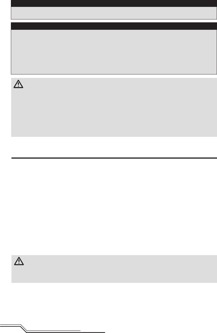
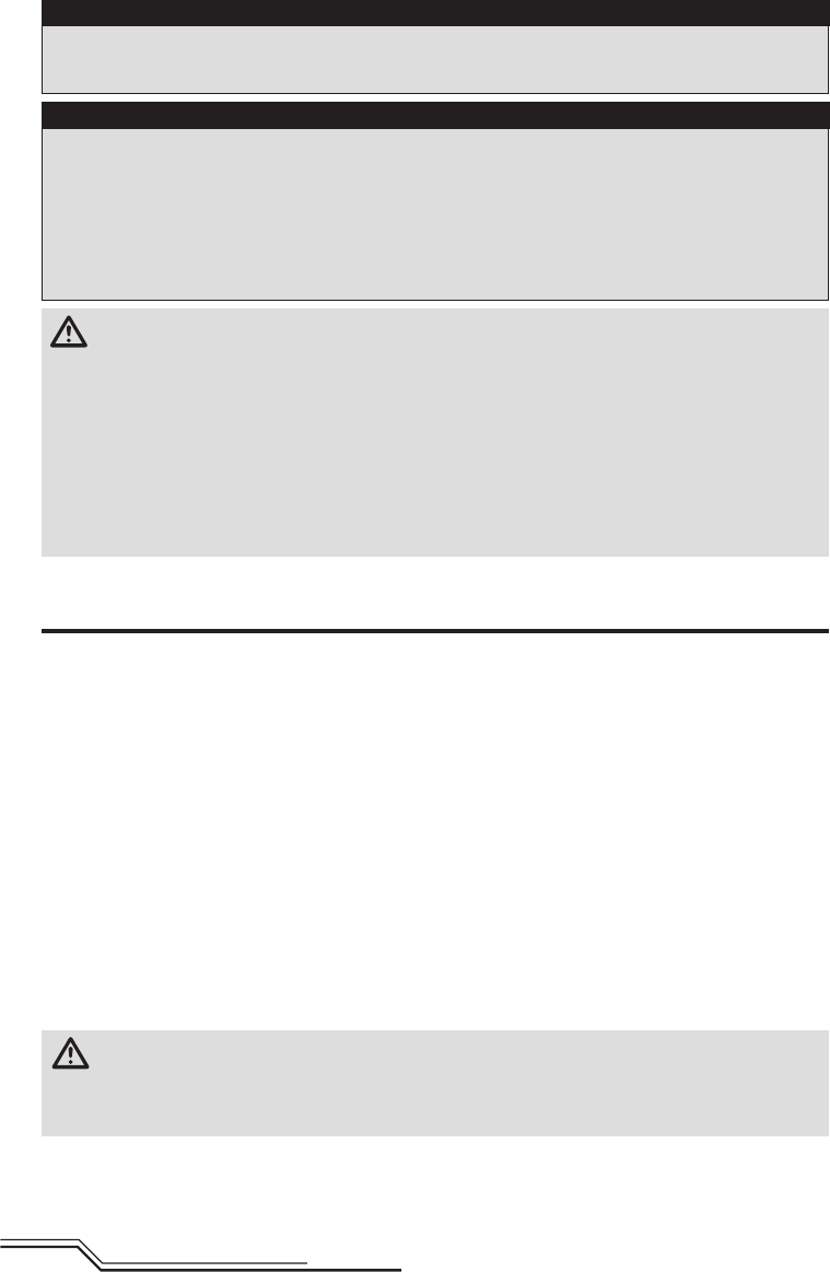
Box Contents
• Blade 120 S
• 500mAh 1S 3.7V 25C Li-Po Battery
• 1S Li-Po USB Charger
• LP6DSM SAFE Transmitter (RTF Only)
• 4 AA Batteries (RTF Only)
Table of Contents
Length 12.6 in (320mm)
Height 4.25 in (108mm)
Main Rotor Diameter 13 in (330mm)
Tail Rotor Diameter 2.75 in (70mm)
Flying Weight 3.74 oz (106 g)
Specifications
To register your product online,visit www.bladehelis.com
Box Contents ..................................................................... 3
First Flight Preparation ....................................................... 4
Flying Checklist .................................................................. 4
Charging Warnings ............................................................. 4
Battery Charging ................................................................ 4
Installing the Transmitter Batteries (RTF) .............................. 5
Transmitter Setup (BNF) ...................................................... 5
Installing the Flight Battery ................................................. 8
Transmitter and Receiver Binding ........................................ 8
RTF Transmitter Controls ................................................... 9
Control Tests .................................................................... 10
Understanding the Primary Flight Controls .........................10
SAFE® Technology ............................................................ 11
Panic Recovery ................................................................ 11
Flying the 120 S .............................................................. 11
Drift Calibration ................................................................ 12
Post-Flight Inspection and Maintenance Checklist ..............12
Troubleshooting Guide ...................................................... 12
Exploded View.................................................................. 14
Parts List ......................................................................... 14
Limited Warranty .............................................................. 15
Warranty and Service Contact Information ......................... 16
FCC Information ............................................................... 16
IC Information .................................................................. 16
Compliance Information for the European Union ................. 16
4
EN
NOTICE: Charge only batteries that are cool to the touch
and are not damaged. Look at the battery to make
sure it is not damaged e.g., swollen, bent, broken or
punctured.
1. Insert the charger into a USB port.
2. Properly connect the battery to the charger lead.
3. Always disconnect the fl ight battery from the charger
immediately upon completion of charging.
CAUTION: Only use chargers specifi cally designed
to charge the included Li-Po battery. Failure to do
so could result in fi re, causing injury or property damage.
CAUTION: Never exceed the recommended
charge rate.
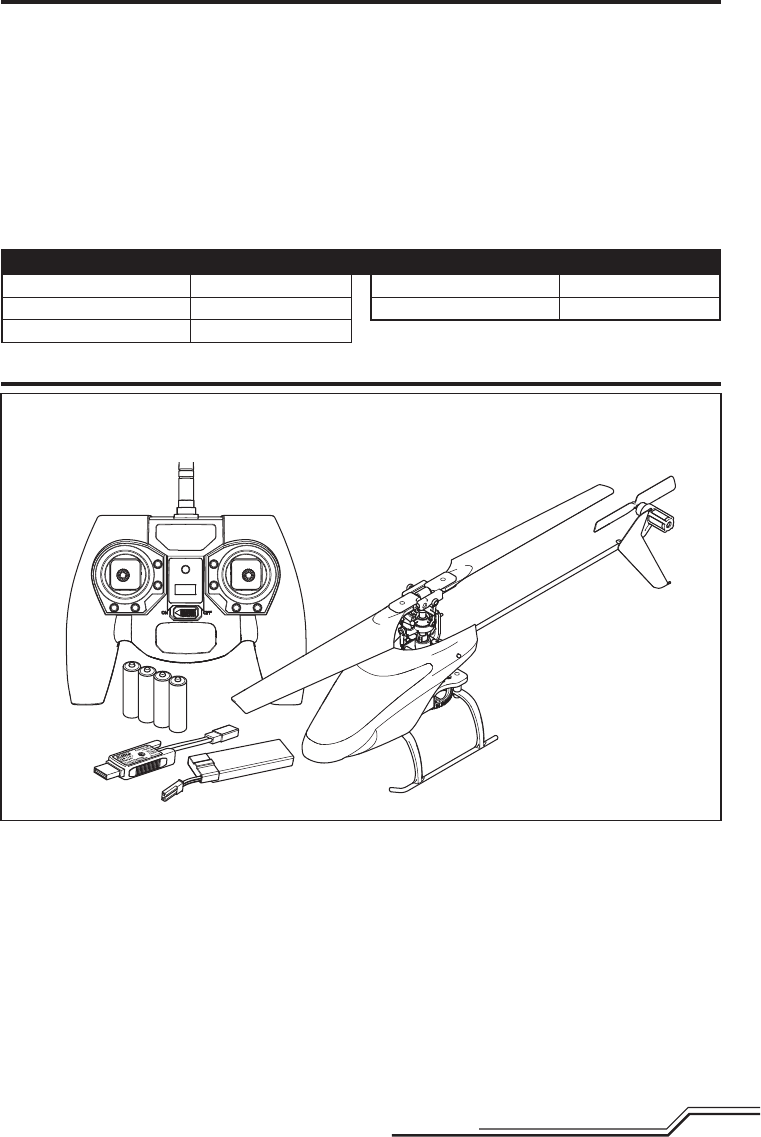
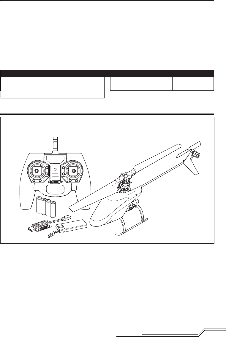
LED Indications
When you make the connection successfully, the LED on
the charger turns solid red, indicating charging has begun.
Charging a fully discharged (not over-discharged) 500mAh
battery takes approximately 60 minutes. The light goes off
when the charge is complete.
CHARGING (Solid Red)
MAX CHARGE (OFF)
CAUTION: Once charging is complete, immedi-
ately remove the battery. Never leave a battery
connected to the charger.
Charging Warnings
Battery Charging
First Flight Preparation
• Remove and inspect contents
• Begin charging the fl ight battery
• Install the batteries in the transmitter (RTF only)
• Program your computer transmitter (BNF only)
• Install the fl ight battery in the helicopter
(once it has been fully charged)
• Bind your transmitter (BNF only)
• Familiarize yourself with the controls
• Find a suitable area for fl ying
Flying Checklist
❏Always turn the transmitter on fi rst
❏ Plug the fl ight battery into the lead from the ESC
❏ Allow the receiver and ESC to initialize and arm properly
❏Fly the model
❏Land the model
❏ Unplug the fl ight battery from the ESC
❏Always turn the transmitter off last
USB Li-Po
Charger
EFLC1010
SOLID RED LED
–Charging
DC Input:5.0V 500mA
DC Output:4.2V 500mA
LED OFF
–Charge
Complete
CAUTION: All instructions and warnings must be
followed exactly. Mishandling of Li-Po batter-
ies can result in a fi re, personal injury and/or property
damage.
• NEVER LEAVE CHARGING BATTERIES UNATTENDED.
• NEVER CHARGE BATTERIES OVERNIGHT.
• By handling, charging or using the included Li-Po
battery, you assume all risks associated with lithium
batteries.
• If at any time the battery begins to balloon or swell,
discontinue use immediately. If charging or discharging,
discontinue and disconnect. Continuing to use, charge
or discharge a battery that is ballooning or swelling can
result in fi re.
• Always store the battery at room temperature in a dry
area for best results.
• Always transport or temporarily store the battery in a
temperature range of 40–120º F (5–49° C).
• Do not store battery or model in a car or direct sunlight.
If stored in a hot car, the battery can be damaged or
even catch fi re.
• Always charge batteries away from fl ammable
materials.
• Always inspect the battery before charging
• Always disconnect the battery after charging, and
let the charger cool between charges.
• Always constantly monitor the temperature of the
battery pack while charging.
• ONLY USE A CHARGER SPECIFICALLY DESIGNED TO
CHARGE LI-PO BATTERIES. Failure to charge the battery
with a compatible charger may cause a fi re resulting in
personal injury and/or property damage.
• Never discharge Li-Po cells to below 3V under load.
• Never cover warning labels with hook and loop strips.
• Never charge batteries outside recommended levels.
• Never charge damaged batteries.
• Never attempt to dismantle or alter the charger.
• Never allow minors to charge battery packs.
• Never charge batteries in extremely hot or cold places
(recommended between 40–120° F or
(5–49° C) or place in direct sunlight.
5EN
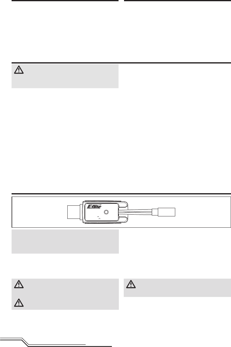
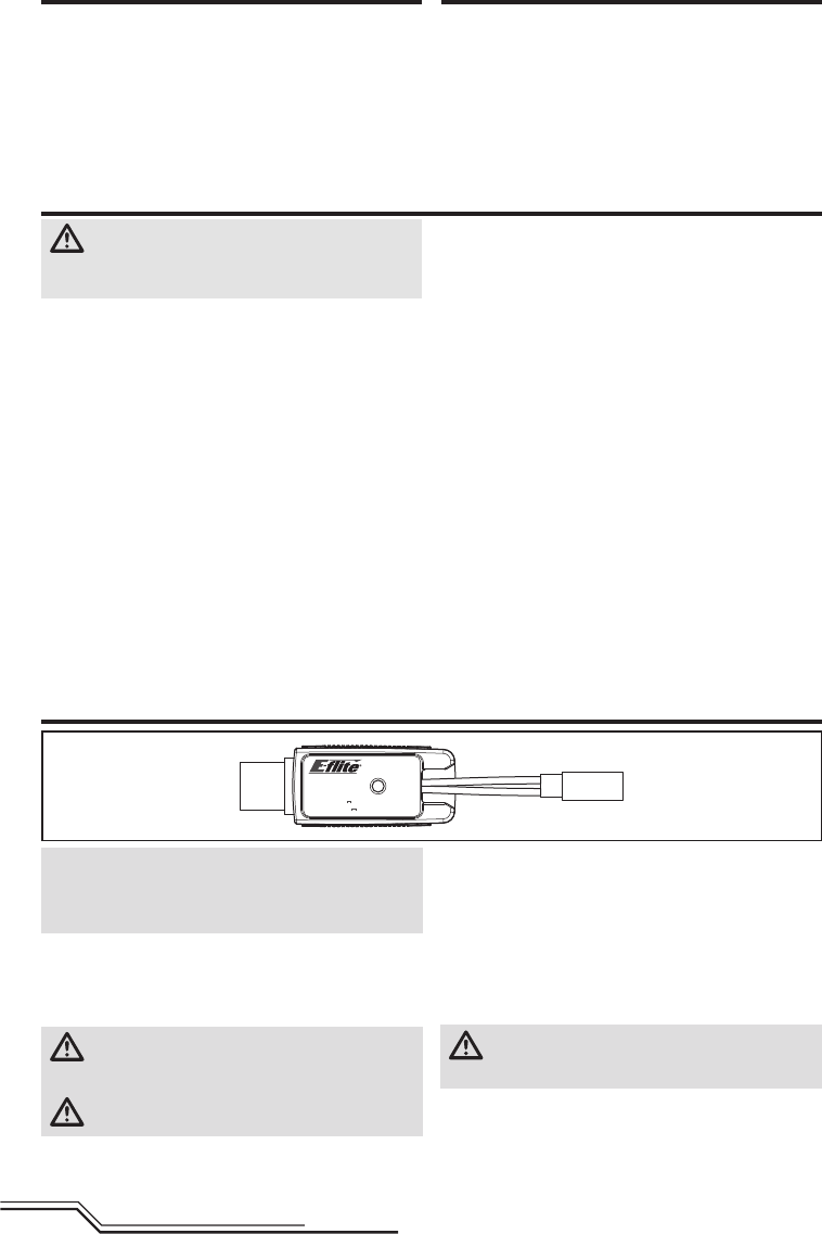
Installing the Transmitter Batteries (RTF)
Replace the transmitter batteries when the
transmitter beeps.
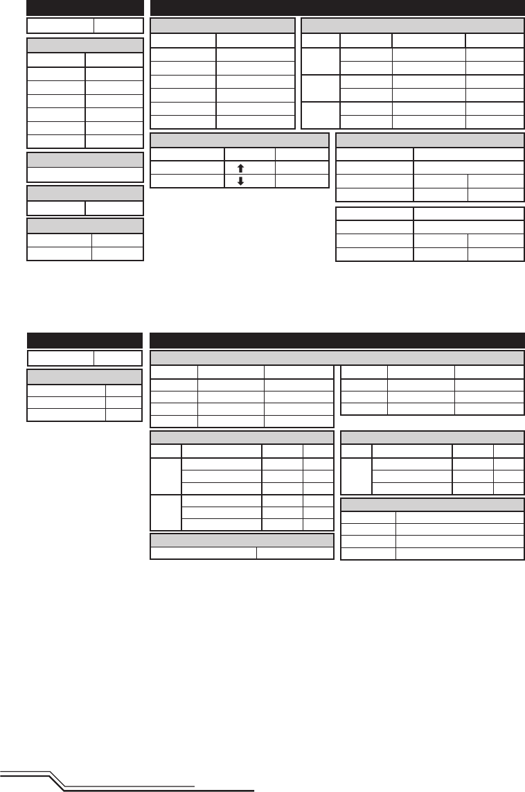
Transmitter Setup (BNF)
Program your transmitter before attempting to bind or fl y
the helicopter. Transmitter programming values are shown
below for the Spektrum DX6i, DX7s, DX6, DX7, DX8, DX9
and DX18.
The fi les for models using Spektrum™ transmitters with
AirWare™ software are also available for download online
at www.spektrumrc.com.
Your helicopter is also compatible with Spektrum DXe radios
with software version 1.3 or higher. Use the directions below
to reverse channel 6, or use the appropriate programming
cable and the PC or mobile app to program the DXe. We
recommend downloading the Blade 120 S DXe model setup
available at www.spektrumrc.com.
If you are programming your DXe using the PC or mobile
app, make sure the "Transmitter Channels" value is set to
the default of 7. If for any reason this value is changed
to 9, the 120 S will bind to the DXe, but will not respond to
control inputs.
If your DXe was included in another Blade Ready To Fly (RTF)
helicopter, the transmitter software will have to be updated
using the appropriate programming cable and either the
PC or mobile app available at www.spektrumrc.com.
Please note, the switch confi guration used for DXe transmit-
ters included with the Blade 230 S RTF and Micro AH-64
Apache RTF varies from the standard DXe layout.
After reversing channel 6, bind the transmitter and
helicopter normally.
Flight modes are controlled by the Flight Mode switch.
Panic Mode is controlled by the Bind/Panic/Trainer button.
Once bound, the LED in the helicopter should glow blue for
fl ight modes 0 and 1 (Stability, Low-Angle and High-Angle
Modes), and glow red for fl ight mode 2 (Agility mode).
If the LED glows blue in all three fl ight modes, channel 6
has not been reversed correctly. Use the directions above
to reverse channel 6.
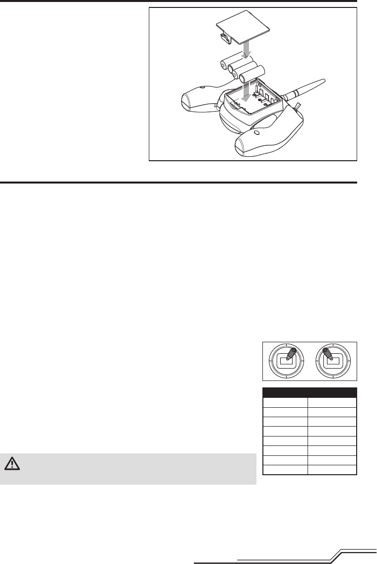
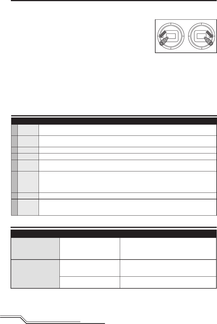
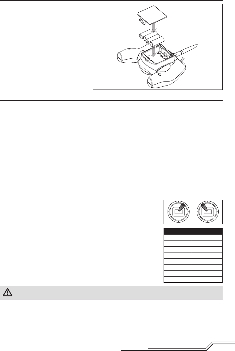
To use the DXe transmitter with the Blade 120 S, channel 6 must be reversed.
To reverse channel 6:
1. While powering on the DXe, hold the left and right sticks in the top-inside corners
as shown.
2. Re-center the sticks after the transmitter beeps. The LED will fl ash slowly.
3. To select a channel to reverse, move the right stick to the left or right and allow it
to re-center. Move the stick to the right to select the next channel. Move the stick
to the left to select the previous channel. The LED will fl ash rapidly corresponding
to the channel selected, as shown in the table. Select channel 6.
4. To reverse the selected channel, move the right stick up or down. The LED will
change color to indicate the new channel direction.
The LED will fl ash Orange to indicate the channel is normal.
The LED will fl ash Red to indicate the channel is reversed.
5. To store the changes, power off the DXe.
CAUTION: During the subsequent power up, always verify the throttle
direction is correct and keep clear of the motor and rotor blades. Failure to do
so may result in injury or damage to the product.
DXe
LED Flashes Channel
1 1-Throttle
2 2-Aileron
3 3-Elevator
4 4-Rudder
5 5-Flight Mode
6 6-Panic
7 7-Flaps
8 8-Aux Channel
6
EN
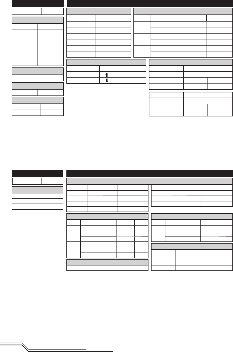
Servo Setup
FUNCTION LISTSYSTEM SETUP
DX7s
Throttle Cut
Switch Mix 1
D/R & Expo
Chan
Switch Pos (FLAP)
D/R
Expo*
AILE
0 100/100 0
1 100/100 0
2 75/75 0
ELEV
0 100/100 0
1 100/100 0
2 75/75 0
D/R & Expo
Chan
Switch Pos (FLAP)
D/R
Expo*
RUDD
0 100/100 0
1 100/100 0
2 75/75 0
Timer
Mode Count Down
Time 5:00 Tone
Start Throttle Out
Pos 25%
Chan Travel Reverse
THR 100/100 Normal
AIL 100/100 Normal
ELE 100/100 Normal
RUD 100/100 Normal
Chan Travel Reverse
GER 100/100 Normal
AX1 100/100 Reverse
AX2 100/100 Normal
Panic Mode Operation
Trainer/Bind Button
Pressed = Panic Mode On
Released = Panic Mode Off
Model Type ACRO
SW Select
Trainer Aux 1
Flap Gear
All Others INH
* Use of "Expo" is not necessary for successful fl ight of the 120 S. The pilot may adjust this setting to tailor the
sensitivity of the helicopter around neutral if desired.
D/R & Expo
Chan Sw Pos D/R Expo*
AILE 0 100 INH
1 75 INH
ELEV 0 100 INH
1 75 INH
RUDD 0 100 INH
1 75 INH
Timer
Down Timer 5:00
Switch THR CUT
ADJUST LISTSETUP LIST
DX6i
TRAVEL ADJ
Channel Travel
THRO 100/100
AILE 100/100
ELEV 100/100
RUDD 100/100
GEAR 100/100
PITC 100/100
REVERSE
Channel Direction
THRO N
AILE N
ELEV N
RUDD N
GEAR R
FLAP N
Modulation Type
AUTO DSMX-ENABLE
D/R COMBI
D/R SW AILE
Model Type Acro
Panic Mode Operation
Gyro Switch: Pos 0 = Panic Mode Off
Pos 1 = Panic Mode On
Flight Mode Operation
Gear Sw: Pos 0, Elev D/R Sw: 0 or 1 = Stability, Low-Angle Mode
Gear Sw: Pos 1, Elev D/R Sw: 0 = Stability, High-Angle Mode
Gear Sw: Pos 1, Elev D/R Sw: 1 = Agility Mode
Flight Mode Operation
FLAP Sw: Pos 0 = Stability, Low-Angle Mode
Pos 1 = Stability, High-Angle Mode
Pos 2 = Agility Mode
Mixing
MIX 1 ACT
GEAR > GEAR ACT
RATE D 0% U –100%
SW GEAR TRIM – INH
MIX 2 ACT
GEAR > GEAR ACT
RATE D 0% U +100%
SW ELE D/R TRIM – INH
FLAPS
FLAP ELEV
NORM 100 0
LAND 100 0
7EN
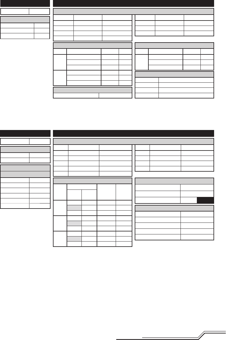
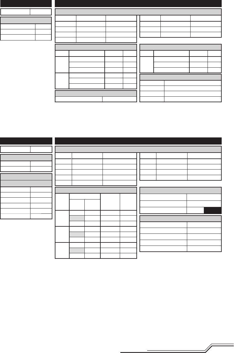
Servo Setup
FUNCTION LISTSYSTEM SETUP
DX8
SYSTEM SETUP
Model Type Airplane
F-Mode Setup
Switch 1 Switch B
Switch 2 Inhibit
Channel Assign
Channel Input
1 Throttle N/A
2 Aileron N/A
3 Elevator N/A
4 Rudder N/A
5 Gear B
6 AUX 1 I
Throttle Cut
Position –130
Switch Switch H
01
Throttle Cut
Switch Mix 1
Chan Travel Reverse
THR 100/100 Normal
AIL 100/100 Normal
ELE 100/100 Normal
RUD 100/100 Normal
GER 100/100 Normal
Chan Travel Reverse
AX1 100/100 Reverse
AX2 100/100 Normal
AX3 100/100 Normal
AX4 100/100 Normal
Servo Setup
FUNCTION LIST
DX6, DX7 (Gen 2), DX9, DX18
Timer
Mode Count Down
Time 5:00
Start Throttle Out
Over 25%
One Time Inhibit
D/R & Expo
Chan
Switch (F) Pos
D/R Expo*DX6 DX7, 9,
18
AILE 0 0 100/100 0
1 100/100 0
1 2 75/75 0
ELEV 0 0 100/100 0
1 100/100 0
1 2 75/75 0
RUDD 0 0 100/100 0
1 100/100 0
1 2 75/75 0
D/R & Expo
Chan
Switch Pos (AIL D/R)
D/R
Expo*
AILE
0 100/100 0
1 100/100 0
2 75/75 0
ELEV
0 100/100 0
1 100/100 0
2 75/75 0
D/R & Expo
Chan
Switch Pos (AIL D/R)
D/R
Expo*
RUDD
0 100/100 0
1 100/100 0
2 75/75 0
Timer
Mode Count Down
Time 5:00 Tone
Start Throttle Out
Pos 25%
Chan Travel Reverse
THR 100/100 Normal
AIL 100/100 Normal
ELE 100/100 Normal
RUD 100/100 Normal
Chan Travel Reverse
GER 100/100 Normal
AX1 100/100 Reverse
AX2 100/100 Normal
Panic Mode Operation
Trainer/Bind Button
Pressed = Panic Mode On
Released = Panic Mode Off
Model Type ACRO
SW Select
Trainer Aux 1
F Mode Gear
All Others INH
Panic Mode Operation
Bind / I Button
Pressed = Panic Mode On
Released = Panic Mode Off
* Use of "Expo" is not necessary for successful fl ight of the 120 S. The pilot may adjust this setting to tailor the
sensitivity of the helicopter around neutral if desired.
Flight Mode Operation
F MODE Sw: Pos 0 = Stability, Low-Angle Mode
Pos 1 = Stability, High-Angle Mode
Pos 2 = Agility Mode
Flight Mode Operation
Sw B: Pos 0 = Stability, Low-Angle Mode
Pos 1 = Stability, High-Angle Mode
Pos 2 = Agility Mode
8
EN
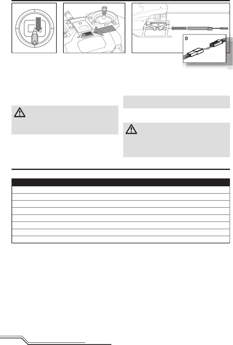
Transmitter and Receiver Binding
1. Lower the throttle stick to the lowest position (A) and
center all trims.
2. Set the Flight Mode Switch to Stability Mode (FM0)
3. Power ON the transmitter (B).
4. Slide the fl ight battery fully into the mount of the heli-
copter frame (C).
5. Connect the power lead to the battery (D), noting the
correct polarity.
CAUTION: Connecting the battery to the control
board with reversed polarity will cause damage
to the control board, the battery or both. Damage caused
by incorrectly connecting the battery is not covered
under warranty.
6. Place the helicopter on a fl at
surface and leave it still until
the red LED changes to blue and glows solid, indicating
initialization is complete.
If the LED on the control board fl ashes rapidly, proceed
to the Transmitter and Receiver Binding section to bind
the helicopter and transmitter.
NOTICE: Do not allow the helicopter to move until the
LED on the control board is solid blue.
If you experience issues during initialization, refer to the
Troubleshooting Guide at the back of the manual.
CAUTION: Always disconnect the Li-Po battery
from the aircraft when not fl ying to avoid over-
discharging the battery. Batteries discharged to a voltage
lower than the lowest approved voltage may become
damaged, resulting in loss of performance and potential
fi re when batteries are charged.
Installing the Flight Battery
A B C
MLP6DSM Binding Procedure (RTF)
1. Disconnect the fl ight battery from the helicopter.
2. Center all trims on your transmitter.
3. Power off the transmitter and move the throttle stick to the down/off position.
4. Connect the fl ight battery in the helicopter. The Blue LED on the control board fl ashes after 5 seconds.
5. When the Blue LED light is fl ashing, push in and hold down the left stick* while powering on the transmitter (you will hear a ‘click’).
6. Release the left stick. The transmitter will beep and the power LED will blink.
7. The helicopter is bound when the LED on the control board is solid blue (not blinking).
8. Disconnect the fl ight battery and power the transmitter off.
* The trigger switch may also be used for the binding procedure.
If you encounter problems, obey binding instructions and refer to the troubleshooting guide for other instructions. If needed, contact
the appropriate Horizon Product Support offi ce. For a list of compatible DSM® transmitters, please visit www.bindnfl y.com.
Your RTF transmitter comes prebound to the model. If you need to re-bind, follow the directions below.
n
dg
low
ss
oli
d
ind
ica
tin
g
9EN
To bind or re-bind your helicopter to your chosen transmitter, follow the directions below.
General Binding Procedure (BNF)
1. Disconnect the fl ight battery from the helicopter.
2. Refer the Transmitter Setup Table to correctly setup your transmitter.
3. Lower the throttle stick to the lowest position and center all trims on your transmitter.
4. Power off the transmitter and move all switches to the 0 position. Move the throttle to the low/off position.
5. Connect the fl ight battery to the control board. The control board LED fl ashes, indicating it is in bind mode.
6. Put the transmitter into bind mode while powering on the transmitter.
7. Release the bind button/switch after 2–3 seconds. The helicopter is bound when the LED on the receiver turns solid.
8. Disconnect the fl ight battery and power the transmitter off.
CAUTION: When using a Futaba® transmitter with a Spektrum™ DSM2® module, you must reverse the throttle
channel and re-bind. Refer to your Spektrum module manual for binding and failsafe instructions. Refer to your
Futaba transmitter manual for instructions on reversing the throttle channel.
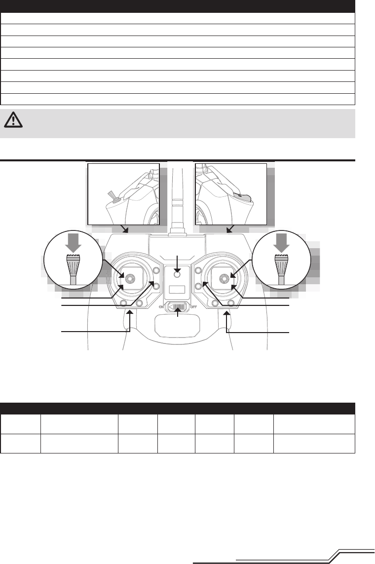
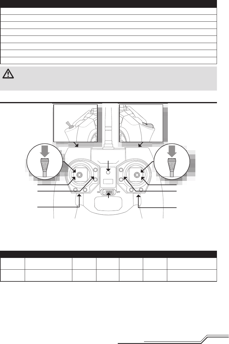
RTF Transmitter Controls
D
E
C
B
Flight mode switch
When pressed down, trim buttons make a sound that
increases or decreases in pitch at each pressing. The
middle or neutral trim position is heard as a middle tone
in the pitch range of the sounds. The end of the control
range is sounded by a series of beeps.
Dual Rate Selection
The control sensitivity can be changed by pressing and
releasing the right control stick. The LED on the transmitter
will show solid for high sensitivity (default) and fl ashing for
low sensitivity.
Bind switch Dual rate
switch
Panic Recovery
ABCDE F
Mode 1 Aileron (Left/Right)
Throttle (Up/Down)
Throttle
Trim
Aileron
Trim
Rudder
Trim
Elevator
Trim
Rudder (Left/Right)
Elevator (Up/Down)
Mode 2 Aileron (Left/Right)
Elevator (Up/Down)
Elevator
Trim
Aileron
Trim
Rudder
Trim
Throttle
Trim
Rudder (Left/Right)
Throttle (Up/Down)
ON/OFF
Switch
Power LED/fl ight
mode indicator
AF
10
EN
Elevator
Elevator down Elevator up
Left Side View Left Side View
Aileron
Aileron left Aileron right
Rear ViewRear View
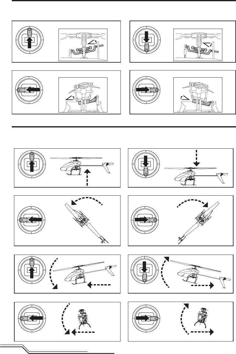
Control Tests
Test the controls prior to the fi rst fl ight to ensure the servos, linkages and parts operate correctly. Ensure the throttle is in
the low position when doing the control tests.
Understanding the Primary Flight Controls
If you are not familiar with the controls of your 120 S, take a few minutes to familiarize yourself with them before at-
tempting your fi rst fl ight.
Throttle
Throttle down
Throttle up
Left Side View Left Side View
Descend
Climb
Elevator
Forward
Elevator down Elevator up Backward
Left Side View Left Side View
Rudder
Rudder left Rudder right Nose Yaws Right
Nose Yaws Left
Aileron
Aileron left Left Aileron right Right
Rear ViewRear View

11 EN
Consult your local laws and ordinances before choosing a
location to fl y your aircraft.
We recommend fl ying your aircraft outside in calm winds
(3 MPH or less) or inside a large gymnasium. Always avoid
fl ying near houses, trees, wires and buildings. You should
also be careful to avoid fl ying in areas where there are
many people, such as busy parks, schoolyards or soccer
fi elds.
It is best to fl y from a smooth fl at surface as this will allow
the model to slide without tipping over. Keep the helicopter
approximately 2 ft (600mm) above the ground. Keep the tail
pointed toward you during initial fl ights to keep the control
orientation consistent. Releasing the stick in Stability or
Intermediate Modes will allow the helicopter to level itself
and activating the Panic Switch will level the helicopter
quickly. If you become disoriented, slowly lower the throttle
stick to land softly. During initial fl ights, only attempt hover-
ing the model in one spot and takeoff and landing.
Takeo
Place the model onto a fl at, level surface free of obstacles
and walk back 30 feet (10 meters). Slowly increase the
throttle until the model is approximately 2 ft. (600mm)
off the ground and check the trim so the model fl ies as
desired. Once the trim is adjusted, begin fl ying the model.
Typical fl ight time for the included battery is approxi-
mately 10 minutes.
Hovering
Making small corrections on the transmitter, try to hold
the helicopter in one spot. If fl ying in calm winds, the
model should require almost no corrective inputs. After
moving the cyclic stick and returning it to center the
model should level itself. The model may continue to
move due to inertia. Move the cycle stick in the opposite
direction to stop the movement.
Do not use the trims on the transmitter to eliminate drift.
If the helicopter does not hold a reasonable hover in calm
conditions, perform the Drift Calibration.
After you become comfortable hovering, you can progress
into fl ying the model to different locations, keeping the tail
pointed towards you at all times. You can also ascend and
descend using the throttle stick. Once you're comfortable
with these maneuvers, you can attempt fl ying with the tail
in different orientations. It is important to keep in mind
that the fl ight control inputs will rotate with the helicopter,
so always try to picture the control inputs relative to the
nose of the helicopter. For example, forward will always
drop the nose of the helicopter.
Low Voltage Cuto (LVC)
LVC decreases the power to the motors when the battery
voltage gets low. When the motor power decreases and
the red LED on the ESC fl ashes, land the aircraft immedi-
ately and recharge the fl ight battery.
LVC does not prevent the battery from over-discharge
during storage.
NOTICE: Repeated fl ying to LVC will damage the battery.
Landing
To land, slowly decrease the throttle while in a low-level
hover. After landing, disconnect and remove the battery
from the aircraft after use to prevent trickle discharge.
Fully charge your battery before storing it. During storage,
make sure the battery charge does not fall below 3V per
cell.
Flight Modes
Stability, Low-Angle Mode (FM0): The receiver LED
shows solid blue. This fl ight mode allows a low bank
angle and slower fl ight speed. When the cyclic stick is
released the model will self-level.
Stability, High-Angle Mode (FM1): The receiver LED
shows solid blue. This fl ight mode allows a high bank
angle and faster fl ight speed. When the cyclic stick is
released the model will self-level.
Agility Mode (FM2): The receiver LED shows solid red.
The bank angle is not limited. When the cyclic stick is
released the model will not self-level.
Flying the 120 S
Revolutionary SAFE® (Sensor Assisted Flight Envelope)
technology uses an innovative combination of multi-axis
sensors and software that allows model aircraft to know
its position relative to the horizon. This spatial awareness
is utilized to create a controlled fl ight envelope the aircraft
can use to maintain a safe region of bank and pitch angles
so you can fl y more safely. Far beyond stability, this level of
protection offers multiple modes so the pilot can choose to
develop his or her skills with a greater degree of security
and fl ight control that always feels crisp and responsive.
SAFE technology delivers:
• Flight envelope protection you can enable at the fl ip
of a switch.
• Multiple modes let you adapt SAFE technology to your
skill level instantly.
Best of all, sophisticated SAFE technology doesn’t require
any work to enjoy. Every aircraft with SAFE installed is
ready to use and optimized to offer the best possible fl ight
experience.
FlySAFERC.com
Technology
®
Panic Recovery
• Immediate recovery to a safe fl ying attitude.
• Move the throttle to 50% and return all other transmit-
ter controls to neutral for the quickest recovery.
• This mode is intended to provide the pilot with the
confi dence to continue to improve their fl ight skills.
If you get into distress while fl ying in any mode, pull and
hold the Bind/Panic Switch and move the control sticks to
their neutral position. The SAFE technology will return the
aircraft to a stable attitude, if the aircraft is at a suffi cient
height with no obstacles in its path. Release the Panic
Switch to turn off Panic Recovery and return to the current
fl ight mode.
12
EN
Post-Flight Inspection and Maintenance Checklist
Dri Calibration
√
Ball Links Make sure the plastic ball link holds the control ball, but is not tight (binding) on the ball. When a link is too loose on
the ball, it can separate from the ball during fl ight and cause a crash. Replace worn ball links before they fail.
Cleaning Make sure the battery is not connected before cleaning. Remove dust and debris with a soft brush or a dry, lint-free
cloth.
BearingsReplace bearings when they become notchy (sticky in places when turning) or draggy.
Wiring Make sure the wiring does not contact moving parts. Replace damaged wiring and loose connectors.
Fasteners Make sure there are no loose screws, other fasteners or connectors. Do not over-tighten metal screws in plastic
parts. Tighten screws so the parts are mated together, then turn the screw only 1/8th of a turn more.
Rotors
Make sure there is no damage to rotor blades and other parts which move at high speed. Damage to these parts
includes cracks, burrs, chips or scratches. Replace damaged parts before fl ying. Verify both main rotor blades have
the correct and equal tension in the blade grips. When the helicopter is held up sideways, the main blades should
support their own weight. When the helicopter is shaken lightly, the blades should fall.
Tail Inspect the tail rotor for damage and replace if necessary. Inspect the tail boom for any damage and replace if necessary.
Mechanics
Inspect the main frame and landing gear for damage and replace if necessary. Check the mainshaft for vertical play
and adjust the locking collar if necessary. Verify that the main gear mesh is correct and that no tight spots exist in
the 360 degree rotation. Inspect all wires for damage and replace as necessary.
Troubleshooting Guide
Problem Possible Cause Solution
Helicopter is bound to a
Spektrum DXe but will not
respond to control input
The transmitter is in 9-channel mode
Using the appropriate DXe programming cable and PC or
mobile app, either change the transmitter to 7-channel mode
or download the Blade 120 S model setup fi le to your
transmitter from www.spektrumrc.com
Helicopter will not respond
to throttle
Throttle too high and/or throttle trim
is too high
Disconnect the fl ight battery, place the throttle stick in the
lowest position and lower the throttle trim a few clicks.
Connect the fl ight battery and allow the model to initialize
Helicopter moved during initialization Disconnect the flight battery and re-initialize the helicopter
while keeping the helicopter from moving
The helicopter has been calibrated in the factory before
shipment, but it is possible that a crash will cause
mechanical distortion of the frame, resulting in a slight
drift in Stability mode. In this situation, please follow the
calibration procedure.
Before beginning the calibration procedure, fully charge the
fl ight battery and ensure the helicopter and transmitter are
bound properly, per the binding instructions.
To Calibrate the Blade 120 S:
1. After initialization, move the transmitter sticks to the
bottom, outside corners, as shown in the illustration.
When the red
and blue LEDs
on the main
fl ight control
board glow solid,
calibration mode
is active.
2. Release the sticks.
3. Slowly advance the throttle to bring the helicopter into
a low hover. The red and blue LEDs fl ash continuosly
to indicate the calibration process has begun. Hold
the hover for approximately 15 seconds, using as little
control input as possible to keep the helicopter steady.
4. Land the helicopter by slowly lowering the throttle.
5. After landing, press the bind/panic button to complete
the calibration process. The LED will show solid blue.

13 EN
Problem Possible Cause Solution
Helicopter has reduced fl ight
time or is underpowered
Flight battery charge is low Completely recharge the fl ight battery
Flight battery is damaged Replace the fl ight battery and follow the fl ight battery
instructions
Flight conditions might be too cold Make sure the battery is warm (room temperature) before use
LED on receiver fl ashes
rapidly and aircraft will not
respond to transmitter (during
binding)
Transmitter too near aircraft during
binding process
Power off the transmitter. Move the transmitter a larger distance
from the aircraft. Disconnect and reconnect the fl ight battery to
the aircraft. Follow the binding instructions
Bind switch or button was not held
while transmitter was powered on Power off transmitter and repeat bind process
Aircraft or transmitter is too close to
large metal object, wireless source or
another transmitter
Move aircraft and transmitter to another
location and attempt binding again
LED on the receiver fl ashes
rapidly and the helicopter will
not respond to the transmitter
(after binding)
Less than a 5-second wait between
fi rst powering on the transmitter and
connecting the fl ight battery to the
helicopter
Leave the transmitter powered on. Disconnect and reconnect
the fl ight battery to the helicopter
The helicopter is bound to a differ-
ent model memory (ModelMatch™
transmitters only)
Select the correct model memory on the transmitter. Discon-
nect and reconnect the fl ight battery to the helicopter
Flight battery or transmitter battery
charge is too low Replace or recharge batteries
Aircraft or transmitter is too close to
large metal object, wireless source or
another transmitter
Move aircraft and transmitter to another
location and attempt connecting again
Helicopter vibrates or shakes
in fl ight
Damaged rotor blades, spindle, blade
grips, main gear teeth or cracked
main shaft.
Check main rotor blades, blade grips, main gear and main
shaft for cracks, chips or missing teeth. Replace damaged
parts. Replace bent spindle
Rotor head linkages not connected
correctly
Connect the rotor head linkages to the short ball links on the
swashplate
Model does not hold level/
Panic recovery does not level.
Random movements in fl ight
Vibration
Verify the receiver is properly attached to the helicopter. Verify
that no wires are contacting the receiver. Inspect and balance
all rotating components. Verify the main shaft and tail rotor
adapter are not damaged or bent. Inspect mechanics for
broken or damaged parts and replace as necessary
Tail oscillation/wag or poor
performance
Loose tail boom, damaged tail rotor,
loose bolts, vibration
Verify that the boom is tight and completely inserted into the
frame. Inspect the tail rotor for damage. Verify the tail motor
mount is tight. Replace any damaged or worn components
Drift in calm winds Vibration, damaged linkage, dam-
aged servo
Under normal operation the transmitter trims should not
require adjustment and the center positions are memorized
during initialization. If you fi nd that trim adjustments are
necessary after take off, verify the balance of all rotating
components, ensure the linkages are not damaged and make
sure the servos are in proper working condition. Perform the
Drift Calibration procedure
Drift in wind Normal
The model will drift with the wind but should remain level in
fl ight. Simply hold the cyclic stick in the necessary position
to keep the model stationary. The model must lean into the
wind to remain stationary, if the model remains level then it
will drift with the wind
Severe vibration Rotating component out of balance
Check the main shaft, tail rotor, main rotor blades, main
frame and adapter for damage, replace as necessary.
Vibration must be minimized for Panic Recovery and Return
to Level functions to work properly
14
EN
1
10
23
3
4
13
26
5
7
8
20
9
25
6
15
16
12
17
24
18
18
19
11 15
22 22
14
14
221
21
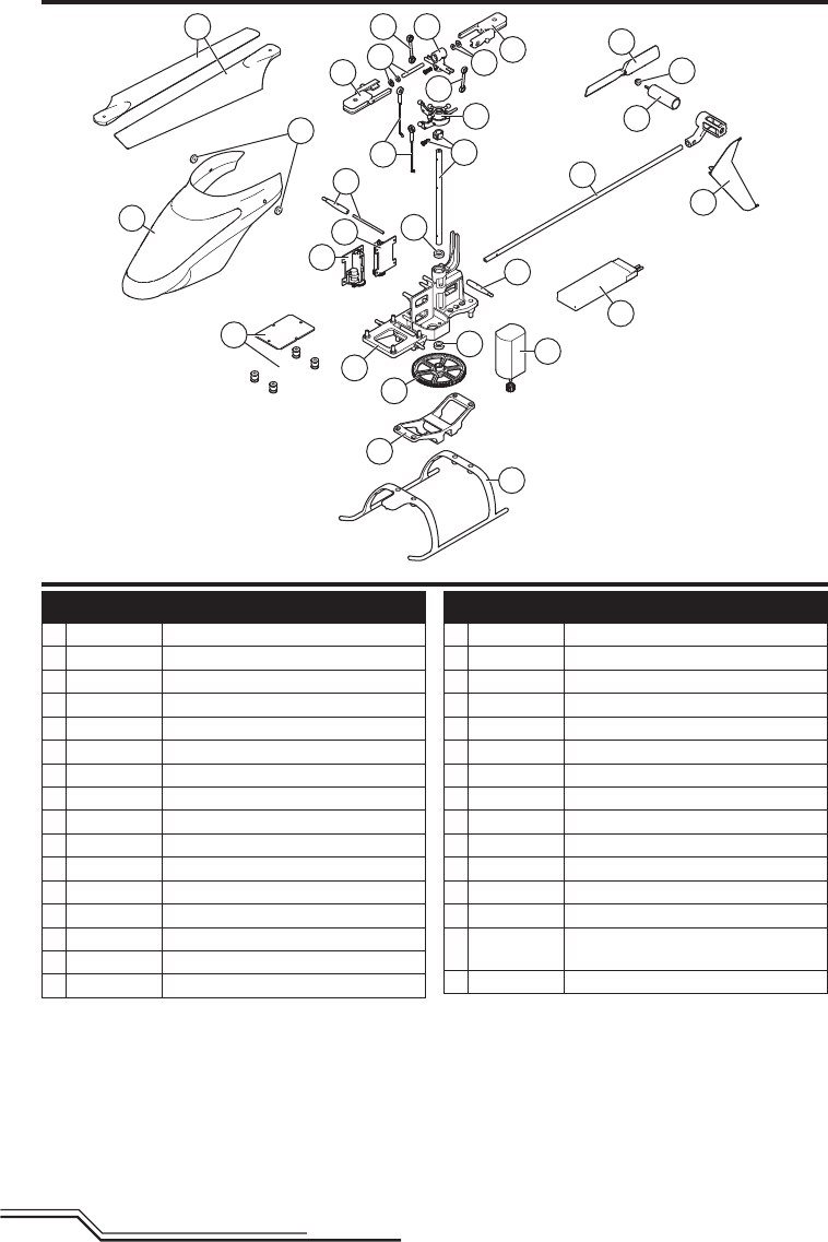
Exploded View
Parts List
Part # Description
BLH4100 120 S RTF
BLH4180 120 S BNF
1 SPMSH2029L Linear Long, 35mm lead
2 SPMSH2030L Linear Long, 60mm lead
3 BLH4101 Main Control Board
4 BLH4102 Tail Boom Set
5 BLH4103 Main Motor
6 BLH4104 Main Frame
7 BLH4105 Main Shaft w/hardware
8 BLH4106 Swashplate
9 BLH4107 Canopy
10 BLH4108 Tail Fin
11 BLH4111 Main Blades w/screws
12 BLH4112 Battery Frame
13 BLH3117 Tail Rotor
14 BLH3705 Canopy Mounts
Part # Description
15 BLH3115 Rotor Head Linkage
16 BLH3106 Main gear
17 BLH3709 Landing gear Set
18 BLH3114 Main Blade grips with Hardware and screws
19 BLH3108 Servo Pushrod Set with Ball link (2)
20 BLH3112 Main Rotor Hub with Hardware
21 BLH3128 Main Shaft Bearing 4 x 7 x 2
22 BLH3113 Feathering Spindle w/O-rings and bushings
23 BLH3129 Tail Motor
24 EFLB5001S25 1S, 500 mAh, 25C LiPo Battery, JST
25 BLH3121 Canopy Mounting Grommets (8)
26 BLH3125 Tail Motor Protective Sleeve
BLH4109 Screw set: 120 S
EFLRMLP6 MLP6DSM transmitter 6 channel SAFE
transmitter (RTF only)
EFLC1010 1S, 500 mAh USB LiPo Charger, JST

15 EN
Limited Warranty
What this Warranty Covers
Horizon Hobby, LLC, (Horizon) warrants to the original purchas-
er that the product purchased (the “Product”) will be free from
defects in materials and workmanship at the date of purchase.
What is Not Covered
This warranty is not transferable and does not cover (i) cos-
metic damage, (ii) damage due to acts of God, accident, mis-
use, abuse, negligence, commercial use, or due to improper
use, installation, operation or maintenance, (iii) modification of
or to any part of the Product, (iv) attempted service by anyone
other than a Horizon Hobby authorized service center, (v)
Product not purchased from an authorized Horizon dealer, (vi)
Product not compliant with applicable technical regulations, or
(vii) use that violates any applicable laws, rules, or regulations.
OTHER THAN THE EXPRESS WARRANTY ABOVE, HORIZON
MAKES NO OTHER WARRANTY OR REPRESENTATION, AND
HEREBY DISCLAIMS ANY AND ALL IMPLIED WARRANTIES,
INCLUDING, WITHOUT LIMITATION, THE IMPLIED WARRANTIES
OF NON-INFRINGEMENT, MERCHANTABILITY AND
FITNESS FOR A PARTICULAR PURPOSE. THE PURCHASER
ACKNOWLEDGES THAT THEY ALONE HAVE DETERMINED THAT
THE PRODUCT WILL SUITABLY MEET THE REQUIREMENTS OF
THE PURCHASER’S INTENDED USE.
Purchaser’s Remedy
Horizon’s sole obligation and purchaser’s sole and exclusive
remedy shall be that Horizon will, at its option, either (i) ser-
vice, or (ii) replace, any Product determined by Horizon to be
defective. Horizon reserves the right to inspect any and all
Product(s) involved in a warranty claim. Service or replace-
ment decisions are at the sole discretion of Horizon. Proof
of purchase is required for all warranty claims. SERVICE OR
REPLACEMENT AS PROVIDED UNDER THIS WARRANTY IS THE
PURCHASER’S SOLE AND EXCLUSIVE REMEDY.
Limitation of Liability
HORIZON SHALL NOT BE LIABLE FOR SPECIAL, INDIRECT,
INCIDENTAL OR CONSEQUENTIAL DAMAGES, LOSS OF
PROFITS OR PRODUCTION OR COMMERCIAL LOSS IN ANY
WAY, REGARDLESS OF WHETHER SUCH CLAIM IS BASED IN
CONTRACT, WARRANTY, TORT, NEGLIGENCE, STRICT LIABILITY
OR ANY OTHER THEORY OF LIABILITY, EVEN IF HORIZON HAS
BEEN ADVISED OF THE POSSIBILITY OF SUCH DAMAGES.
Further, in no event shall the liability of Horizon exceed the
individual price of the Product on which liability is asserted. As
Horizon has no control over use, setup, final assembly, modi-
fication or misuse, no liability shall be assumed nor accepted
for any resulting damage or injury. By the act of use, setup
or assembly, the user accepts all resulting liability. If you as
the purchaser or user are not prepared to accept the liability
associated with the use of the Product, purchaser is advised to
return the Product immediately in new and unused condition
to the place of purchase.
Law
These terms are governed by Illinois law (without regard to
conflict of law principals). This warranty gives you specific
legal rights, and you may also have other rights which vary
from state to state. Horizon reserves the right to change or
modify this warranty at any time without notice.
WARRANTY SERVICES
Questions, Assistance, and Services
Your local hobby store and/or place of purchase cannot pro-
vide warranty support or service. Once assembly, setup or use
of the Product has been started, you must contact your local
distributor or Horizon directly. This will enable Horizon to better
answer your questions and service you in the event that you
may need any assistance. For questions or assistance, please
visit our website at www.horizonhobby.com, submit a Product
Support Inquiry, or call the toll free telephone number refer-
enced in the Warranty and Service Contact Information section
to speak with a Product Support representative.
Inspection or Services
If this Product needs to be inspected or serviced and is com-
pliant in the country you live and use the Product in, please
use the Horizon Online Service Request submission process
found on our website or call Horizon to obtain a Return
Merchandise Authorization (RMA) number. Pack the Product
securely using a shipping carton. Please note that original
boxes may be included, but are not designed to withstand
the rigors of shipping without additional protection. Ship via a
carrier that provides tracking and insurance for lost or dam-
aged parcels, as Horizon is not responsible for merchandise
until it arrives and is accepted at our facility. An Online Service
Request is available at http://www.horizonhobby.com/con-
tent/_service-center_render-service-center. If you do not have
internet access, please contact Horizon Product Support to
obtain a RMA number along with instructions for submitting
your product for service. When calling Horizon, you will be
asked to provide your complete name, street address, email
address and phone number where you can be reached during
business hours. When sending product into Horizon, please
include your RMA number, a list of the included items, and a
brief summary of the problem. A copy of your original sales
receipt must be included for warranty consideration. Be sure
your name, address, and RMA number are clearly written on
the outside of the shipping carton.
NOTICE: Do not ship Li-Po batteries to Horizon. If you have
any issue with a Li-Po battery, please contact the appropriate
Horizon Product Support office.
Warranty Requirements
For Warranty consideration, you must include your
original sales receipt verifying the proof-of-purchase
date. Provided warranty conditions have been met, your
Product will be serviced or replaced free of charge. Service or
replacement decisions are at the sole discretion of Horizon.
Non-Warranty Service
Should your service not be covered by warranty, ser-
vice will be completed and payment will be required
without notification or estimate of the expense unless
the expense exceeds 50% of the retail purchase cost.
By submitting the item for service you are agreeing to pay-
ment of the service without notification. Service estimates are
available upon request. You must include this request with
your item submitted for service. Non-warranty service esti-
mates will be billed a minimum of ½ hour of labor. In addition
you will be billed for return freight. Horizon accepts money
orders and cashier’s checks, as well as Visa, MasterCard,
American Express, and Discover cards. By submitting any item
to Horizon for service, you are agreeing to Horizon’s Terms and
Conditions found on our website http://www.horizonhobby.
com/content/_service-center_render-service-center.
ATTENTION: Horizon service is limited to Product com-
pliant in the country of use and ownership. If received,
a non-compliant Product will not be serviced. Further,
the sender will be responsible for arranging return
shipment of the un-serviced Product, through a carrier
of the sender’s choice and at the sender’s expense.
Horizon will hold non-compliant Product for a period
of 60 days from notification, after which it will be dis-
carded.
10/15
16
EN
Warranty and Service Contact Information
Country of Purchase Horizon Hobby Contact Information Address
United States of
America
Horizon Service Center
(Repairs and Repair Requests)
servicecenter.horizonhobby.com/
RequestForm/
4105 Fieldstone Rd
Champaign, Illinois, 61822 USA
Horizon Product Support
(Product Technical Assistance)
productsupport@horizonhobby.com
888-959-2304
Sales sales@horizonhobby.com
888-959-2304
United Kingdom Service/Parts/Sales:
Horizon Hobby Limited
sales@horizonhobby.co.uk Units 1–4 , Ployters Rd, Staple Tye
Harlow, Essex, CM18 7NS, United
Kingdom
+44 (0) 1279 641 097
Germany Horizon Technischer Service service@horizonhobby.de Christian-Junge-Straße 1
25337 Elmshorn, Germany
Sales: Horizon Hobby GmbH +49 (0) 4121 2655 100
France Service/Parts/Sales:
Horizon Hobby SAS
infofrance@horizonhobby.com 11 Rue Georges Charpak
77127 Lieusaint, France
+33 (0) 1 60 18 34 90
Compliance Information for the European Union
EU Compliance Statement:
RTF:
Horizon Hobby, LLC hereby declares that this
product is in compliance with the essential requirements
and other relevant provisions of the R&TTE, EMC, and LVD
Directives.
BNF:
Horizon Hobby, LLC hereby declares that this product is
in compliance with the essential requirements and other
relevant provisions of the R&TTE and EMC Directives.
A copy of the EU Declaration of Conformity is available online at:
http://www.horizonhobby.com/content/support-render-compliance.
Instructions for disposal of WEEE by users in the European Union
This product must not be disposed of with
other waste. Instead, it is the user’s respon-
sibility to dispose of their waste equipment
by handing it over to a designated collections
point for the recycling of waste electrical and
electronic equipment. The separate collection
and recycling of your waste equipment at the time of disposal
will help to conserve natural resources and make sure that it
is recycled in a manner that protects human health and the
environment. For more information about where you can drop
off your waste equipment for recycling, please contact your lo-
cal city offi ce, your household waste disposal service or where
you purchased the product.
FCC Information
This device complies with part 15 of the FCC rules.
Operation is subject to the following two conditions:
(1) This device may not cause harmful interference,
and (2) this device must accept any interference received,
including interference that may cause undesired operation.
CAUTION: Changes or modifi cations not ex-
pressly approved by the party responsible for
compliance could void the user’s authority to operate
the equipment.
This product contains a radio transmitter with wire-
less technology which has been tested and found to be
compliant with the applicable regulations governing a radio
transmitter in the 2.400GHz to 2.4835GHz frequency range.
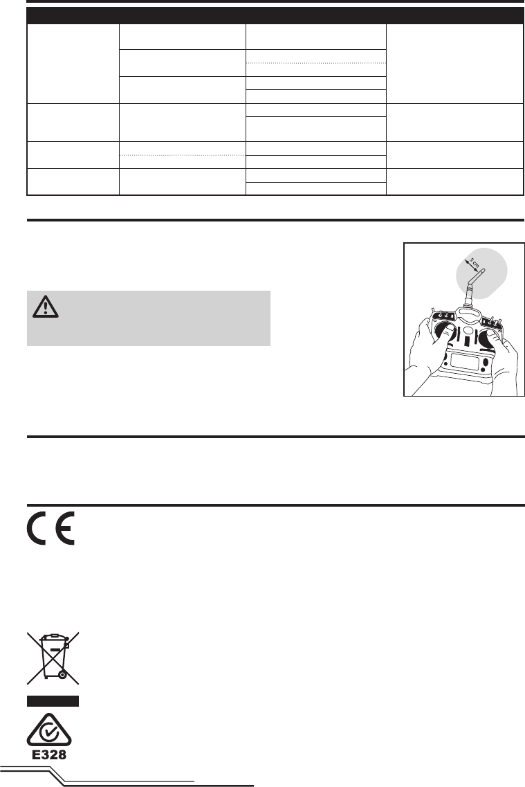
Antenna Separation Distance
When operating your
transmitter, please be sure
to maintain a separation
distance of at least 5 cm
between your body (excluding
fi ngers, hands, wrists, ankles
and feet) and the antenna
to meet RF exposure safety
requirements as determined
by FCC regulations.
The following illustrations
show the approximate 5 cm
RF exposure area and typical
hand placement when operating your transmitter.
IC Information
This device complies with Industry Canada license-exempt
RSS standard(s). Operation is subject to the following two
conditions:
(1) this device may not cause interference, and (2) this
device must accept any interference, including interference
that may cause undesired operation of the device.

17 EN
18
DE
WARNUNG: Lesen Sie die GESAMTE Bedienungsanleitung, um sich vor dem Betrieb mit den Produktfunktionen
vertraut zu machen. Wird das Produkt nicht korrekt betrieben, kann dies zu Schäden am Produkt oder persönli-
chem Eigentum führen oder schwere Verletzungen verursachen.
Dies ist ein hochentwickeltes Hobby-Produkt. Es muss mit Vorsicht und gesundem Menschenverstand betrieben werden
und benötigt gewisse mechanische Grundfähigkeiten. Wird dieses Produkt nicht auf eine sichere und verantwortungs-
volle Weise betrieben, kann dies zu Verletzungen oder Schäden am Produkt oder anderen Sachwerten führen. Dieses
Produkt eignet sich nicht für die Verwendung durch Kinder ohne direkte Überwachung eines Erwachsenen. Versuchen
Sie nicht ohne Genehmigung durch Horizon Hobby, LLC das Produkt zu zerlegen, es mit inkompatiblen Komponenten
zu verwenden oder auf jegliche Weise zu erweitern. Diese Bedienungsanleitung enthält Anweisungen für Sicherheit,
Betrieb und Wartung. Es ist unbedingt notwendig, vor Zusammenbau, Einrichtung oder Verwendung alle Anweisungen
und Warnhinweise im Handbuch zu lesen und zu befolgen, damit es bestimmungsgemäß betrieben werden kann und
Schäden oder schwere Verletzungen vermieden werden.
Die folgenden Begriffe werden in der gesamten Produktliteratur verwendet, um auf unterschiedlich hohe Gefahren-
risiken beim Betrieb dieses Produkts hinzuweisen:
HINWEIS: Wenn diese Verfahren nicht korrekt befolgt werden, können sich möglicherweise Sachschäden UND
geringe oder keine Gefahr von Verletzungen ergeben.
ACHTUNG: Wenn diese Verfahren nicht korrekt befolgt werden, ergeben sich wahrscheinlich Sachschäden UND die
Gefahr von schweren Verletzungen.
WARNUNG: Wenn diese Verfahren nicht korrekt befolgt werden, ergeben sich wahrscheinlich Sachschäden,
Kollateralschäden und schwere Verletzungen ODER mit hoher Wahrscheinlichkeit oberfl ächliche Verletzungen.
• Halten Sie stets in allen Richtungen einen Sicherhe-
itsabstand um Ihr Modell, um Zusammenstöße oder
Verletzungen zu vermeiden. Dieses Modell wird von
einem Funksignal gesteuert, das Interferenzen von
vielen Quellen außerhalb Ihres Einfl ussbereiches
unterliegt. Diese Interferenzen können einen
augenblicklichen Steuerungsverlust verursachen.
• Betreiben Sie Ihr Modell immer auf einer Freifl äche ohne
Fahrzeuge in voller Größe, Verkehr oder Menschen.
• Befolgen Sie stets sorgfältig die Anweisungen und
Warnhinweise für das Modell und jegliche optionalen
Hilfsgeräte (Ladegeräte, Akkupacks usw.).
• Bewahren Sie alle Chemikalien, Klein- und Elektroteile
stets außerhalb der Reichweite von Kindern auf.
• Setzen Sie Geräte, die für diesen Zweck nicht speziell
ausgelegt und geschützt sind, niemals Wasser aus.
Feuchtigkeit kann die Elektronik beschädigen.
• Stecken Sie keinen Teil des Modells in den Mund, da
dies zu schweren Verletzungen oder sogar zum Tod
führen kann.
• Betreiben Sie Ihr Modell nie mit fast leeren Senderakkus.
• Halten Sie das Fluggerät immer in Sicht und unter Kontrolle.
• Gehen Sie sofort auf Motor Aus bei Rotorberührung.
• Verwenden Sie immer vollständig geladene Akkus.
• Lassen Sie immer den Sender eingeschaltet wenn das
Fluggerät eingeschaltet ist.
• Nehmen Sie vor der Demontage des Fluggerätes die
Akkus heraus.
• Halten Sie bewegliche Teile immer sauber.
• Halten Sie die Teile immer trocken.
• Lassen Sie Teile immer erst abkühlen bevor Sie sie anfassen.
• Nehmen Sie die Akkus/Batterien nach Gebrauch heraus.
• Betreiben Sie Ihr Fluggerät niemals mit beschädigter
Verkabelung.
• Fassen Sie niemals bewegte Teile an.
HINWEIS
Alle Anweisungen, Garantien und anderen zugehörigen Dokumente können im eigenen Ermessen von Horizon Hobby,
LLC jederzeit geändert werden. Die aktuelle Produktliteratur fi nden Sie auf horizonhobby.com unter der Registerkarte
„Support“ für das betreffende Produkt.
Spezielle Bedeutungen
Sicherheitsvorkehrungen und Warnhinweise
Nicht geeignet für Kinder unter 14 Jahren. Dies ist kein Spielzeug.
WARNUNG GEGEN GEFÄLSCHTE PRODUKTE: Sollten Sie jemals eine Spektrum Komponente ersetzen wollen,
kaufen Sie die benötigen Ersatzteile immer bei Horizon Hobby oder einem von Horizon Hobby autorisiertem
Händler um die hohe Qualität des Produktes zu gewährleisten. Horizon Hobby LLC lehnt jedwede Haftung, Garantie
oder Unterstützung sowie Kompatibilitäts- oder Leistungsansprüche zu DSM oder Spektrum in Zusammenhang mit
gefälschten Produkten ab.
19 DE
Lieferumfang
Inhaltsangabe
Länge 320mm
Höhe 108mm
Hauptrotordurchmesser 330mm
Heckrotordurchmesser 70mm
Fluggewicht 106 g
Spezifikationen
Lieferumfang .............................................................19
Vorbereitung für den Erstfl ug ......................................20
Checkliste zum Fliegen ...............................................20
Akku-Warnhinweise ...................................................20
Laden des Flugakkus .................................................20
Einsetzen der Senderbatterien (RTF) ............................21
Sendereinstellungen (BNF) ..........................................21
Einsetzen des Flugakkus ............................................24
Binden von Sender und Empfänger .............................24
Senderfunktionen (RTF) ..............................................25
Kontrolltests ..............................................................26
Einführung in die Hauptsteuerfunktionen .....................26
SAFE Technologie .......................................................27
Panikrettung .............................................................. 27
Fliegen des 120 S ......................................................27
Driftkalibrierung .........................................................28
Kontrollen nach dem Flug und Wartung .......................28
Leitfaden zur Problemlösung .......................................28
Explosionszeichnung ..................................................30
Teileliste .................................................................... 30
Garantie und Service Informationen .............................31
Garantie und Service Kontaktinformationen ..................32
Rechtliche Informationen für die Europäische Union .....32
Sie können Ihr Produkt online unter
www.bladehelis.com registrieren.
• Blade 120 S
• 500mAh 1S 3,7V 25C Li-Po Akku
• 1S USB Lipo Lader
• LP6DSM SAFE Sender (nur in RTF version)
• 4 AA Batterien (nur in RTF version)
20
DE
HINWEIS: Laden Sie Akkus nur, wenn sie auf Umge-
bungstemperatur abgekühlt sind. Schauen Sie sich
den Akku an und stellen Sie sicher, dass dieser nicht
beschädigt oder aufgequollen ist.
1. Stecken Sie den Lader in den USB Port.
2. Schließen Sie den Akku an das Ladekabel an.
3. Entnehmen Sie den Akku immer aus dem Lader, sobald
der Ladevorgang beendet ist.
ACHTUNG: Verwenden Sie nur Ladegeräte, die für
LIPO Akkus vorgesehen sind. Nichtbeachtung kann
zu Feuer, Beschädigungen oder Verletzungen führen.
ACHTUNG: Überschreiten Sie niemals die
vorgesehene Ladezeit.
LED Anzeigen
Bei erfolgreicher Verbindung von Akku und Lader leuchtet die
LED rot und zeigt an, dass der Ladevorgang begonnen hat.
Das Laden eines vollständig entladenen Akkus von 500mAh
dauert ca. 60 Minuten. Die LED erlischt, wenn der Akku
vollständig geladen ist.
Laden: LED rot
Fertig geladen: LED aus
ACHTUNG: Entnehmen Sie den Akku aus dem
Lader, sobald dieser fertig geladen ist. Belassen Sie
den Akku niemals im Lader.
ACHTUNG: Alle Anweisungen und Warnhinweise
müssen genau befolgt werden. Falsche Handha-
bung von Li-Po-Akkus kann zu Brand, Personen- und/oder
Sachwertschäden führen.
• LASSEN SIE LADEN VON AKKUS UNBEAUFSICHTIGT.
• LADEN SIE NIEMALS AKKUS ÜBER NACHT.
• Durch Handhabung, Aufl adung oder Verwendung des mitge-
lieferten Li-Po-Akkus übernehmen Sie alle mit Lithiumakkus
verbundenen Risiken.
• Sollte der Akku zu einem beliebigen Zeitpunkt beginnen, sich
aufzublähen oder anzuschwellen, stoppen Sie die Verwendung
unverzüglich. Falls dies beim Laden oder Entladen auftritt,
stoppen Sie den Lade-/Entladevorgang, und entnehmen Sie
den Akku. Wird ein Akku, der sich aufbläht oder anschwillt,
weiter verwendet, geladen oder entladen, besteht Brandge-
fahr.
• Lagern Sie den Akku stets bei Zimmertemperatur an einem
trockenen Ort.
• Bei Transport oder vorübergehender Lagerung des Akkus
muss der Temperaturbereich zwischen 40°F und 120°F
(ca. 5 – 49°C) liegen. Akku oder Modell dürfen nicht im Auto
oder unter direkter Sonneneinstrahlung gelagert werden. Bei
Lagerung in einem heißen Auto kann der Akku beschädigt
werden oder sogar Feuer fangen.
• Laden Sie die Akkus immer weit entfernt von brennbaren
Materialien.
• Überprüfen Sie immer den Akku vor dem Laden und laden Sie
niemals defekte oder beschädigte Akkus.
• Verwenden Sie ausschließlich ein Ladegerät das speziell für
das Laden von LiPo Akku geeignet ist. Das Laden mit einem
nicht geeignetem Ladegerät kann Feuer und / oder Sachbe-
schädigung zur Folge haben.
• Überwachen Sie ständig die Temperatur des Akkupacks
während des Ladens.
• Trennen Sie immer den Akku nach dem Laden und lassen das
Ladegerät abkühlen.
• Entladen Sie niemals ein LiPo Akku unter 3V pro Zelle unter
Last.
• Verdecken Sie niemals Warnhinweise mit Klettband.
• Lassen Sie niemals Akkus während des Ladens unbeauf-
sichtigt.
• Laden Sie niemals Akkus ausserhalb ihrer sicheren Grenzen.
• Laden Sie nur Akkus die kühl genug zum anfassen sind.
• Versuchen Sie nicht das Ladegerät zu demontieren oder zu
verändern.
• Lassen Sie niemals Minderjährige Akkus laden.
• Laden Sie niemals Akkus an extrem kalten oder heißen
Plätzen (empfohlener Temperaturbereich 5 – 49°) oder im
direkten Sonnenlicht.
Akku-Warnhinweise
Laden des Flugakkus
Vorbereitung für den Erstfl ug
• Entnehmen und überprüfen Sie die Komponenten
• Laden Sie den Flugakku
• Setzen Sie die Batterien in den Sender ein (nur RTF Version)
• Programmieren Sie Ihren Sender (nur BNF Version)
• Setzen Sie den Akku ein wenn er vollständig geladen ist
• Binden von Sender (nur BNF Version)
• Machen Sie sich mit den Kontrollen vertraut
• Finden Sie eine geeignete Fläche zum fl iegen
Checkliste zum Fliegen
❏Schalten Sie immer den Sender zuerst ein
❏Stecken Sie den Flugakku an den Anschluß der ESC
❏Lassen Sie der ESC Kontrolleinheit Zeit zum initialisieren
und armieren
❏Fliegen Sie das Modell
❏Landen Sie das Modell
❏Stecken Sie den Flugakku von der ESC
❏Schalten Sie immer den Sender als letztes aus
USB Li-Po
Charger
EFLC1010
SOLID RED LED
–Charging
DC Input:5.0V 500mA
DC Output:4.2V 500mA
LED OFF
–Charge
Complete
21 DE
Einsetzen der Senderbatterien (RTF)
Ersetzen Sie die Sender Batterien wenn die der
Sender piept.
Sendereinstellungen (BNF)
Sie müssen Ihren Sender zuerst programmieren, bevor Sie den
Helikopter binden oder fl iegen können. Die Werte, die Sie zum
Programmieren Ihres Senders für Spektrum DX6i, DX7s, DX6,
DX7, DX8, DX9 und DX18 Empfänger benötigen, sind unten
angeführt.
Die Spektrum-Modelldateien für AirWare Sender stehen
auch online in der Spektrum Community zum Download zur
Verfügung.
Der Hubschrauber ist ebenfalls mit der Spektrum DXe Fern-
steuerung mit der Softwareversion 1.3 oder höher kompatibel.
Nutzen Sie die unten stehenden Anweisungen um den Kanal 6
zu reversieren oder verwenden Sie das Programmierkabel für
den PC oder die App. Wir empfehlen den Download des Blade
120S DXe Modellspeichers unter www.spektrumrc.com.
Bei der Programmierung der DXe über den PC oder mit der
App achten Sie bitte darauf, dass die Anzahl der Senderkanäle
(Transmitter Channels) auf 7 steht. Sollte der Wert auf 9 geän-
dert worden sein, wird der 120S zwar an den Sender gebunden
aber nicht auf die Steuereingaben reagieren.
Sollte die DXe für einen anderen Blade Ready to Fly (RTF)
Hubschrauber verwendet worden sein muß die Sendersoftware
mit dem Programmierkabel über den PC oder der App, die unter
www.spektrumrc.com verfügbar ist, programmiert werden.
Bitte beachten Sie, dass die Schalterkonfi guration des Blade
230S RTF und Micro AH-64 Apache RTF von dem normalen DXe
Standard abweicht.
Binden Sie nach dem Reversieren des Kanal 6 den
Hubschrauber normal mit dem Sender.
Die Flugmodes werden durch den Flugmodeschalter
kontrolliert.
Der Panikmode wird durch Binde/Panik/ Trainerbutton
kontrolliert.
Nach dem Binden sollte die LED im Hubschrauber blau für die
Flugmodes 0 und 1 (Stabilitäts- und großer Neigewinkel Mode)
und rot für den Flugmode 2 (Agilitätsmode) leuchten.
Sollte die LED bei allen drei Flugmode blau leuchten ist der
Kanal 6 nicht korrekt reversiert worden. Bitte beachten Sie
dann die oben stehenden Anweisungen.
Um den DXe Sender mit dem Blade 120S zu verwenden muss der Kanal 6 reversiert werden.
Um den Kanal 6 zu reversieren:
1. Halten Sie bei dem Einschalten der DXe den linken und rechten Steuerknüppel wie
abgebildet in die oberen inneren Ecken.
2. Bringen Sie die Steuerknüppel zurück in die Mittelstellung nachdem der Sender
gepiept hat. Die LED blinkt dann langsam.
3. Um den Kanal auszuwählen den Sie reversieren möchten, bewegen Sie den rechten
Steuerhebel nach links oder rechts und dann wieder in die Mitte. Bewegen Sie den
Steuerhebel nach rechts um den nächsten Kanal zu wählen, bewegen Sie den Steuer-
hebel nach links um den vorherigen Kanal zu wählen. Die LED blinkt schnell entspre-
chend dem ausgewählten Kanal wie in der Tabelle dargestellt. Wählen Sie Kanal 6.
4. Um den ausgewählten Kanal zu reversieren bewegen Sie den rechten Steuerhebel rauf
oder runter. Die LED wechselt die Farbe um die geänderte Richtung anzuzeigen.
Die LED blinkt orange wenn die Kanalrichtung normal ist.
Die LED blinkt rot um anzuzeigen dass der Kanal reversiert ist.
5. Schalten Sie die DXe um die Änderungen zu speichern.
ACHTUNG: Überprüfen Sie bei dem folgenden Einschalten ob die Gasrichtung korrekt ist und halten sich vom
Motor und Rotorblättern fern. Ein nicht beachten kann zu Verletzungen und zu Schäden am Produkt führen.
DXe
LED Flashes Kanal
1 1-Gas
2 2-Querruder
3 3-Höhenruder
4 4-Seitenruder
5 5-Flug-Modus
6 6-Panik
7 7-Klappen
8 8-Aux-Kanal
22
DE
Servo Setup
FunktionslisteSystemeinstellung
DX7s
Gas Aus
Schalter Mix 1
D/R & Expo
Kanal
Schalter Pos (FLAP)
D/R
Expo*
AILE
0 100/100 0
1 100/100 0
2 75/75 0
ELEV
0 100/100 0
1 100/100 0
2 75/75 0
D/R & Expo
Kanal
Schalter Pos (FLAP)
D/R
Expo*
RUDD
0 100/100 0
1 100/100 0
2 75/75 0
Timer
Mode Count Down
Time 5:00 Tone
Start Gas über
Pos 25%
Kanal Servoweg Laufrichtung
GAS 100/100 Normal
ROL 100/100 Normal
NCK 100/100 Normal
HCK 100/100 Normal
Kanal Servoweg Laufrichtung
FW 100/100 Normal
AX1 100/100 Reverse
AX2 100/100 Normal
Panikmode Funktion
Trainer Binde Button
Gedrückt = Panik Mode Ein
Gelöst = Panikmode Aus
Modelltyp ACRO
SW Select
Trainer Aux 1
Klappen FW
andere AUS
* Zum Fliegen des 120S ist keine Expoprogrammierung nötig. Der Pilot kann sie jedoch nach seinen Wünschen einstellen.
D/R & Expo
Chan Sw Pos D/R Expo*
AILE 0 100 INH
1 75 INH
ELEV 0 100 INH
1 75 INH
RUDD 0 100 INH
1 75 INH
Timer
Down Timer 5:00
Switch THR CUT
ADJUST LISTSETUP LIST
DX6i
TRAVEL ADJ
Channel Travel
THRO 100/100
AILE 100/100
ELEV 100/100
RUDD 100/100
GEAR 100/100
PITC 100/100
REVERSE
Channel Direction
THRO N
AILE N
ELEV N
RUDD N
GEAR R
FLAP N
Modulation Type
AUTO DSMX-ENABLE
D/R COMBI
D/R SW AILE
Model Type Acro
Panik Modeschalter
Gyro Schalter: Pos 0 = Panikmode Aus
Pos 1 = Panikmode Ein
Flugmodes
Gear Schalter : Pos 0, Elev D/R Schalter 0 oder 1 = Stabilitätsmode mit geringen Neigewinkel
Gear Schalter : Pos 1, Elev D/R Schalter 0 = Stabilitätsmode mit großen Neigewinkel
Gear Schalter : Pos 1, Elev D/R Schalter 1 = Agilitäts Mode
Flugmodes
Flap (Klappen) Schalter : Pos. 0 = Stabilitätsmode mit geringen Neigewinkel
Pos. 1 = Stabilitätsmode mit großen Neigewinkel
Pos. 2 = Agilitätsmode
Mixing
MIX 1 ACT
GEAR > GEAR ACT
RATE D 0% U –100%
SW GEAR TRIM – INH
MIX 2 ACT
GEAR > GEAR ACT
RATE D 0% U +100%
SW ELE D/R TRIM – INH
FLAPS
FLAP ELEV
NORM 100 0
LAND 100 0
23 DE
Panikmode Funktion
Trainer Binde Button
Gedrückt = Panik Mode Ein
Gelöst = Panikmode Aus
Servoeinstellung
FunktionslisteSystemeinstellung
DX8
Systemeinstellung
Modelltyp Airplane
Flugzustand
Schalter 1 Schalter B
Schalter 2 Aus
Kanalzuweisung
Eingabekanal
1 Gas N/A
2 Rol N/A
3 Nck N/A
4 Hck N/A
5 FW B
6 AUX 1 I
Gas Aus
Position –130
Schalter Schalter H
01
Gas Aus
Schalter Mix 1
Kanal Servoweg Laufrichtung
GAS 100/100 Normal
ROL 100/100 Normal
NCK 100/100 Normal
HCK 100/100 Normal
FW 100/100 Normal
Kanal Servoweg Laufrichtung
AX1 100/100 Reverse
AX2 100/100 Normal
AX3 100/100 Normal
AX4 100/100 Normal
Servoeinstellung
Funktionsliste
DX6, DX7 (neu), DX9, DX18
Uhr
Mode Herunterzählen
Zeit 5:00
Start Gasknüppel
Über 25%
Einmal Aus
D/R & Expo
Kanal
Schalter
(F) Pos
D/R Expo*DX6 DX7, 9,
18
ROL 0 0 100/100 0
1 100/100 0
1 2 75/75 0
NCK 0 0 100/100 0
1 100/100 0
1 2 75/75 0
HCK 0 0 100/100 0
1 100/100 0
1 2 75/75 0
D/R & Expo
Kanal
Shalter Pos (AIL D/R)
D/R
Expo*
ROL
0 100/100 0
1 100/100 0
2 75/75 0
NCK
0 100/100 0
1 100/100 0
2 75/75 0
D/R & Expo
Kanal
Shalter Pos (AIL D/R)
D/R
Expo*
HCK
0 100/100 0
1 100/100 0
2 75/75 0
Timer
Mode Count Down
Time 5:00 Tone
Start Gas über
Pos 25%
Kanal Servoweg Laufrichtung
GAS 100/100 Normal
ROL 100/100 Normal
NCK 100/100 Normal
HCK 100/100 Normal
Kanal Servoweg Laufrichtung
FW 100/100 Normal
AX1 100/100 Reverse
AX2 100/100 Normal
Modelltyp ACRO
SW Select
Trainer Aux 1
F Mode FW
andere AUS
* Zum Fliegen des 120S ist keine Expoprogrammierung nötig. Der Pilot kann sie jedoch nach seinen Wünschen einstellen.
Flugmodes
Flugmodeschalter : Pos. 0 = Stabilitätsmode mit geringen Neigewinkel
Pos. 1 = Stabilitätsmode mit großen Neigewinkel
Pos. 2 = Agilitätsmode
Flugmodes
Schalter B: Pos. 0 = Stabilitätsmode mit geringen Neigewinkel
Pos. 1 = Stabilitätsmode mit großen Neigewinkel
Pos. 2 = Agilitätsmode
Panikmode Funktion
Binde / I Button
Gedrückt = Panikmode Ein
Gelöst = Panikmode Aus

24
DE
Binden von Sender und Empfänger
1. Bringen Sie den Gashebel auf die unterste
Position (A) und zentrieren alle Trimmungen.
2. Stellen Sie den Flugmodeschalter auf den
Stabilitätsmode (FM0).
3. Schalten Sie den Sender ein (B).
4. Schieben Sie vorsichtig den Flugakku in den Halter am
Hubschrauberrahmen (C).
5. Schließen Sie den Akkustecker am Akku an und achten
dabei auf die korrekte Polarität (D).
ACHTUNG: Der verpolte Anschluss des Akkus
an den Regler beschädigt den Regler, Akku oder
beides. Schäden die durch falschen Anschluss entstan-
den sind werden nicht von der Garantie gedeckt.
6. Stellen Sie den Hubschrauber
auf eine ebene Oberfl äche
und lassen ihn vollkommen still stehen bis die rote LED
die Farbe auf blau ändert und damit anzeigt, dass die
Initialisierung durchgeführt ist.
HINWEIS: Der Hubschrauber muß vollkommen still
stehen bis die LED auf Platine blau leuchtet.
Sollte die Initialisierung nicht wie beschrieben erfolgen,
lesen Sie bitte im Leitfaden zur Problemlösung auf der
Rückseite der Anleitung.
ACHTUNG: Trennen Sie immer den Akku vom
Quadcopter wenn Sie nicht fl iegen um ein
tiefentladen des Akkus zu vermeiden. Akkus die unter die
zulässige Grenze entladen werden können dabei beschä-
digt werden, was zu Leistungsverlust und potentieller
Brandgefahr beim Laden führen kann.
Einsetzen des Flugakkus
A B C
MLP6DSM Bindeprozess (RTF)
1. Trennen Sie den Flugakku vom Hubschrauber.
2. Stellen Sie alle Trimmungen in die Mitte.
3. Schalten Sie den Sender aus und bringen Sie den Gashebel in die niedrigste Position.
4. Schließen Sie den Flugakku an den Hubschrauber an. Die blaue LED auf der Platine blinkt nach 5 Sekunden.
5. Drücken Sie den linken Stick in den Sender bis Sie es klicken hören, halten ihn gedrückt und schalten dann den
Sender ein.
6. Lassen Sie den Stick los. Der Sender piept und die Power LED blinkt.
7. Der Hubschrauber ist gebunden wenn die LED auf der control Einheit blau leuchtet (nicht blinkt).
8. Trennen Sie den Flugakku und schalten den Sender aus.
* Dieser Stickschalter kann ebenfalls für den Bindevorgang verwendet werden.
Wenn Probleme auftreten beachten Sie bitte die Bindeanweisungen und schauen in die Hilfestellung zur Problemlösung.
Kontaktieren Sie falls notwendig den technischen Service von Horizon Hobby. Eine Liste der kompatiblen DSM Sender
sehen Sie unter www.bindnfl y.com.
Ihr RTF Sender ist bereits an das Modell gebunden. Sollten Sie neu binden wollen folgen Sie bitte
den untenstehenden Anweisungen.
ls
teh
en
bis
di
er
ote
LE
D
25 DE
Um ihren Hubschrauber an den gewählten Sender zu binden oder neu zu binden folgen Sie bitte den untenstehenden Anweisungen.
Der Bindevorgang (BNF)
1. Trennen Sie den Flugakku vom Hubschrauber.
2. Entnehmen Sie aus der Sendereinstelltabelle die korrekte Einstellung für ihren Sender.
3. Bringen Sie den Gashebel auf die unterste Position und zentrieren alle Trimmungen auf dem Sender.
4. Schalten Sie den Sender aus und alle Schalter in die 0 Position. Stellen Sie das Gas in die Niedrig / Motor Aus Position.
5. Schließen Sie den Flugakku an die Platine an. Die LED auf der Platine blinkt und zeigt den aktivierten Bindemode an.
6. Aktivieren Sie den Bindenmode des Senders währen Sie ihn einschalten.
7. Lassen Sie den Bindeschalter nach 2-3 Sekunden los. Der Hubschrauber ist gebunden wenn die LED leuchtet.
8. Trennen Sie den Flugakku und schalten den Sender aus.
ACHTUNG: Wenn Sie einen Futaba-Sender mit einem Spektrum DSM-Modul verwenden, müssen Sie den
Gaskanal reversieren (umkehren) und danach das System neu binden. Lesen Sie bitte für den Bindevorgang
und programmieren der Failsafeeinstellungen die Bedienungsanleitung des Spektrum Modules. Zum reversieren des
Gaskanals lesen Sie bitte in der Anleitung des Futaba Senders nach.
Senderfunktionen (RTF)
D
E
C
B
Auswahl Flugmodus
Wenn die Trimmtasten gedrückt werden, geben sie einen
Signalton von sich, der bei jedem erneuten Drücken höher
oder tiefer wird. Die mittlere oder neutrale Trimmstellung
erklingt in der mittleren Tonhöhe. An den äußeren Enden
des Steuerbereichs erklingt eine Tonfolge.
Sensivität der Kontrollen
Die Sensivität der Kontrollen kann durch drücken und lösen
des rechten Steuerknüppels geändert werden. Die LED auf
dem Sender leuchtet für hohe Sensivität (Standard) und
blinkt für niedrige Sensivität.
Binden Auswahl
Dual Rate
Panikrettung
ABCDE F
Modus 1 Querrudder (links/rechts)
Gas (auf/ab) Gastrimm Querrud-
dertrimm
Seitenru-
dertrimm
Höhenru-
dertrimm
Seitenruder (links/rechts)
Höhenruder (auf/ab)
Modus 2 Querrudder (links/rechts)
Höhenruder (auf/ab)
Höhenru-
dertrimm
Querrud-
dertrimm
Seitenru-
dertrimm Gastrimm Seitenruder (links/rechts)
Gas (auf/ab)
EIN/AUS
Schalter
Ein/Aus-LED/fl ug-
modes LED
AF
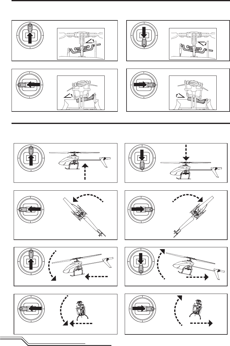
26
DE
Höhenruder
Linke seitenansicht Linke seitenansicht
Querruder
RückansichtRückansicht
Kontrolltests
Testen Sie vor dem Erstfl ug die Kontrollen um sicher zustellen, dass die Servos, Anlenkungen und weitere Teile richtig
arbeiten. Versichern Sie sich, dass das Gas in der niedrigsten Position bei dem Durchführen dieser Tests ist.
Einführung in die Hauptsteuerfunktionen
Wenn Ihnen die Steuerung Ihres 120 S noch nicht geläufi g ist, nehmen Sie sich bitte ein paar Minuten Zeit, umsich mit
ihr vertraut zu machen, bevor Sie Ihren ersten Flug versuchen.
Gasgeber
Sinken
Aufsteigen
Höhenruder
Seitenruder
Querruder
Gasgeber nach
unten
Gasgeber nach
unten
Gasgeber nach
oben
Gasgeber nach
oben
Seitenansicht Seitenansicht
Seitenruder
nach links
RückansichtRückansicht
Vorwärts Rückwärts
Nase dreht nach rechts
Nase dreht nach links
Nach links Nach rechts
Höhenruder
nach unten Höhenruder
nach oben
Seitenruder
nach rechts
Querruder
nach links
Querruder
nach links
Querruder nach
rechts
Querruder nach
rechts
Linke seitenansicht Linke seitenansicht

27 DE
Bitte beachten Sie lokale Bestimmungen bevor Sie sich einen
Platz zum fl iegen aussuchen.
Wir empfehlen den Hubschrauber draußen nur bei leichtem
Wind oder in einer großen Halle zu fl iegen. Vermeiden Sie es
grundsätzlich in der Nähe von Häusern, Bäumen oder Leitungen
zu fl iegen. Meiden Sie bitte auch gut besuchte Plätze wie
belebte Parks, Schulhöfe oder Fußballfelder.
Das beste ist es von einer glatten Oberfl äche zu starten auf
der das Modell etwas rutschen kann ohne umzukippen.
Lassen Sie den Hubschrauber einen halben Meter über dem
Boden schweben. Das Heck sollte dabei zu ihnen zeigen. Das
erleichtert bei den ersten Flügen die Kontrolle. Lassen Sie die
Steuerknüppel im Anfänger- oder Fortgeschrittenen-Mode los,
richtet sich der Hubschrauber selbständig auf. Betätigen Sie den
Panikschalter geschieht das sofort. Sollten Sie die Orientierung
verlieren nehmen Sie langsam das Gas weg um sanft zu landen.
Versuchen Sie während der ersten Flüge das Modell auf einer
Fläche starten und landen zu lassen.
Starten
Stellen Sie das Modell auf eine fl ache ebene Oberfl äche die
frei von Hindernissen ist und treten Sie 10 Meter zurück.
Erhöhen Sie langsam das Gas bis das Modell ca. einen halben
Meter über Grund schwebt.
Die typische Flugzeit mit dem im Lieferumfang enthaltenen
Akku beträgt ca. 10 Minuten.
Schwebefl ug
Versuchen Sie den Hubschrauber mit kleinen Steuerkorrek-
turen auf der Stelle schweben zu lassen. Bei wenig Wind sollte
das Modell so gut wie keine Steuerkorrekturen benötigen.
Wird der Steuerknüppel nach der Eingabe wieder in die Mitte
gestellt, sollte sich das Modell selbständig ausleveln. Der Hub-
schrauber könnte sich durch seine Masseträgheit dabei etwas
in die entgegengesetzte Richtung bewegen. Sie können diese
Bewegung durch eine Steuerbewegung in die entgegeng-
esetzte Richtung beenden.
Verwenden Sie die Trimmungen auf dem Sender nicht um
ein Abdriften zu kompensieren. Sollte der Hubschrauber
einen stationären Schwebefl ug nicht halten führen Sie eine
Driftkalibrierung durch.
Haben Sie sich mit dem Schwebefl ug vertraut gemacht,
fl iegen Sie den Hubschrauber zu verschiedene Positionen. Das
Heck sollte dabei immer ihnen zugewand sein. Lassen Sie den
Hubschrauber dabei etwas steigen und sinken und machen
sich so mit der Gas /Pitch Funktion weiter vertraut. Haben
Sie das gemeistert können Sie beginnen das Heck zu drehen
und so den Hubschrauber in verschiedene Richtungen zu
fl iegen. Sie sollten dabei immer berücksichtigen, dass sich die
notwendige Steuereingaben mit dem Hubschrauber bewegen.
So bringt der der Steuerbefehl Nicken /Vorwärts unabhängig
von der Position des Hubschraubers immer die Nase des
Hubschraubers zum nicken.
Niederspannungsabschaltung (LVC)
Die Niederspannungsabschaltung reduziert die Motorleistung
wenn die Akkuspannung nachlässt. Wird die Motorleistung
weniger und es blinkt die LED auf dem Regler (ESC), landen
Sie bitte unverzüglich und laden den Flugakku wieder auf.
Bitte beachten Sie, dass die Niederspannungsabschaltung den
Akku nicht vor Tiefentladung während der Lagerung schützt.
HINWEIS: Wiederholtes fl iegen in die Niederspannungsab-
schaltung beschädigt den Akku.
Landen
Reduzieren Sie im niedrigen Schwebefl ug das Gas um
zu landen. Trennen Sie nach der Landung den Akku und
nehmen ihn aus dem Hubschrauber um eine Tiefentladung zu
vermeiden. Laden Sie den Akku vor dem Einlagern und achten
während der Lagerung darauf, dass die Akkuspannung nicht
unter 3Volt per Zelle fällt.
Flugmodes
Stabilitätsmode mit geringen Neigewinkel (FM0): Die Emp-
fänger LED leuchtet blau. In diesen Flugmode sind nur geringe
Neigewinkel und langsame Fluggeschwindigkeiten möglich.
Wird die zyklische (Taumelscheiben) Steuerung losgelassen
richtet sich das Modell von selbst wieder auf.
Fliegen des 120 S
Die revolutionäre SAFE Technologie von Horizon Hobby
(Sensor Assited Flight Envelope) verwendet eine innovative
Kombination aus Multi-Achs Sensoren und Software, die es
erlauben, die relative Position des Fluggerätes im Raum je-
derzeit zu bestimmen. Diese dreidimensionale Wahrnehmung
schafft eine schräglagenbegrenzte Fluglage die Sie sicherer
Fliegen läßt. Dabei werden Roll- und Nickwinkel beeinfl usst
und geregelt, um die Flugsicherheit zu erhöhen. Und das
System kann weit mehr, als die Stabilisierung des Fluggerätes.
Die verschiedenen Flugmodi können vom Piloten gemäß
seiner Fähigkeiten individuell eingestellt werden.
SAFE Technologie im Überblick:
• Flugstabilisierung über einen Schalter zuschaltbar.
• Mehrere Modi zur Anpassung von SAFE and die Fähigkeiten
des Piloten.
Und das Beste an allem ist, dass SAFE keine weiteren Einstel-
lungen und Vorbereitungen erfordert. Jedes Modell, welches
mit SAFE ausgestattet wurde, verfügt über eine angepasste
und optimierte Programmierung der Elektronik, um für
maximale Sicherheit und maximalen Flugspaß zu sorgen.
FLYSAFERC.com
Technologie
®
Panikrettung
• Unverzügliche Rettung in eine sichere Fluglage.
• Stellen Sie für die schnellste Rettung das Gas auf 50%
und alle anderen Kontrollen auf Neutral.
• Dieser Mode ist zum sicheren Aufbau Ihrer fl iegerischen
Fähigkeiten geeignet.
Sollten in einem beliebigen Mode bei dem Fliegen Probleme
auftreten, ziehen und halten Sie den Bind- / Panikschalter
und bewegen die Steuerhebel in die Neutralposition. Die
Safetechnologie steuert den Hubschrauber zurück in ein
sichere Fluglage, vorausgesetzt er befi ndet sich in ausrei-
chender Höhe ohne Hindernisse im Flugweg. Lassen Sie den
Panikschalter los um die Funktion wieder zu deaktivieren
und zu dem Flugmode zurück zu kehren.
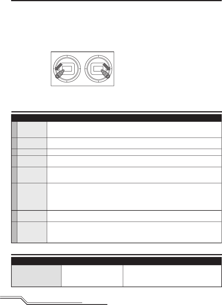
28
DE
Kontrollen nach dem Flug und Wartung
Dri kalibrierung
Leitfaden zur Problemlösung
Problem Mögliche Ursache Lösung
Hubschrauber ist an die
Spektrum DXe gebunden, re-
agiert aber nicht auf
Steuereingaben
Sender befi ndet sich im 9 Kanal Mode
Verwenden Sie das DXe Programmierkabel um über den PC oder
die App den Sender auf den 7 Kanal Mode zu ändern oder laden
Sie die den Blade 120S Modellspeicher auf ihren Sender von
www.spektrumrc.com
Der Hubschrauber wurde ab Werk vor der Auslieferung
kalibriert. Es ist jedoch möglich, dass ein Chrash einen
mechanischen Einfl uss auf den Rahmen ausgeübt hat der
einen Drift zur Folge hat. Folgen Sie in dieser Situation bitte
den Anweisungen zur Kalibrierung.
Laden Sie vor der Kalibrierung den Flugakku und stellen
sicher, dass der Sender mit dem Hubschrauber nach den
Anweisungen gebunden ist.
Kalibrieren des Blade 120S:
1. Bewegen Sie nach
der Initialisierung
die Sender-
steuerhebel wie
abgebildet in die
unteren äußeren
Ecken. Wenn die
roten und blauen
LEDs auf der Platine blinken ist der Kalibrierungsvorgang
aktiviert.
2. Lassen Sie die Steuerknüppel los.
3. Erhöhen Sie langsam das Gas um den Hubschrauber in ei-
nen niedrigen Schwebefl ug zu bringen. Die roten und blauen
LEDs blinken dabei um anzuzeigen, dass der Kalibrierungs-
prozess begonnen hat. Halten Sie den Schwebefl ug für ca
15 Sekunden und verwenden dabei so wenig Steueraus-
schläge wie möglich um den stationären Schwebefl ug
durchzuführen.
4. Landen Sie den Hubschrauber in dem Sie langsam vom Gas
gehen.
5. Drücken Sie nach der Landung den Panik Binde Button um
den Kalibrierungsvorgang abzuschließen. Die LED leuchtet
dann blau.
Stabilitätsmode mit großen Neigewinkel (FM1): Die
Empfänger LED leuchtet blau. In diesen Flugmode sind größere
Neigewinkel und höhere Fluggeschwindigkeiten möglich. Wird
die zyklische (Taumelscheiben) Steuerung losgelassen richtet
sich das Modell von selbst wieder auf.
Agilitätsmode (FM2): Die Empfänger LED leuchtet rot. Der
mögliche Neigewinkel ist nicht begrenzt. Wird die zyklische
(Taumelscheiben) Steuerung losgelassen richtet sich das
Modell nicht von selbst wieder auf.
√
Kugelköpfe- u.
Pfannen
Stellen Sie bitte sicher, dass die Pfanne den Kugelkopf hält ihn aber nicht blockiert. Ist der Kugelkopf zu lose, kann
er sich während des Fluges lösen und einen Absturz verursachen. Ersetzen Sie verschlissene Kugelköpfe und
Pfannen bevor sie versagen.
Reinigung Vergewissern Sie sich vor der Reinigung, dass der Akku nicht angeschlossen ist. Entfernen Sie Staub und
Schmutzrückstände mit einer weichen Bürste oder einem trockenen fusselfreien Tuch.
Lager Ersetzen Sie Lager die nicht mehr frei drehen.
Verkabelung Stellen Sie sicher, dass die Verkabelung keine beweglichen Teile blockiert. Ersetzen Sie beschädigte Verkabelung
und lose Stecker.
Befestigungs-
elemente
Stellen Sie sicher, dass keine Schrauben, andere Befestigungselemente oder Stecker lose sind. Ziehen Sie Me-
tallschrauben in Kunststoffteilen nicht zu stark an. Ziehen Sie Schrauben so an, dass die Teile zusammengefügt
sind, und drehen Sie die Schrauben danach um eine 1/8-Umdrehung.
Rotorblätter
Stellen Sie sicher dass die Rotorblätter und andere Teile die mit hoher Geschwindigkeit drehen keine Beschä-
digungen aufweisen wie: Brüche, Risse, Abplatzer oder Kratzer. Ersetzen Sie beschädigte Teile vor dem fl iegen.
Überprüfen Sie ob beide Rotorblätter gleich korrekt befestigt sind. Wird der Hubschrauber seitlich gehalten sollten
sich beide Rotorblätter im Gewicht ausgleichen. Beginnt der Hubschrauber sich etwas zu schütteln könnten sich
die Rotorblätter lösen.
Heckrotor Überprüfen Sie den Hecktrotor und Heckausleger auf Beschädigungen und ersetzen die Teile wenn notwendig.
Überprüfen Sie dass die Heckrotorabstützungen mit den Kunststoff- und Carbonenden fest sitzen.
Mechanik
Überprüfen Sie den Rahmen und Fahrwerk und ersetzen Teile wenn notwendig. Überprüfen Sie die Hauptrotor-
welle auf Spiel und justieren falls notwendig den Stellring. Überprüfen Sie das Zahnfl ankenspiel und ob sich die
Mechanik ohne Beeinträchtigung um 360° drehen kann. Überprüfen Sie alle Kabel und Verbinder und ersetzen
diese falls notwendig.

29 DE
Problem Mögliche Ursache Lösung
Hubschrauber reagiert nicht
auf Gas
Gas oder Gastrimmung ist zu hoch
Trennen Sie den Flugakku, bringen Sie den Gashebel in die nied-
rigste Postion und stellen die Gastrimmung ein paar Klicks nach
unten. Schließen Sie den Flugakku an und lassen sich das Modell
initialisieren
Hubschrauber wurde während der Initia-
lisierung bewegt Trennen Sie den Flugakku und initialisieren den Hubschrauber
erneut. Dabei muß er vollkommen still stehen
Hubschrauber hat nicht genug
Leistung oder Flugzeit ist
reduziert
Flugakku ist nicht richtig geladen Laden Sie den Akku vollständig
Flugakku ist beschädigt Wechseln Sie den Flugakku und folgen den Anweisungen des
Flugakkus
Temperaturen möglicherweise zu niedrig Stellen Sie sicher dass der Akku vor Gebrauch auf Zimmertem-
peratur ist
LED auf dem Empfänger blinkt
schnell, Hubschrauber reagiert
nicht auf den Sender (während
des Bindevorganges)
Sender war bei dem Binden zu nah am
Hubschrauber
Schalten Sie den Sender aus und vergrößern Sie die Entfernung
zum Flugzeug. Trennen und verbinden den Akku zum Hubschrau-
ber erneut, folgen Sie den Bindenaweisungen
Bindeschalter oder Button wurde beim
Einschalten des Senders nicht gedrückt Schalten Sie den Sender aus und wiederholen den Bindevorgang
Hubschrauber oder Sender steht zu nah
an großen Metallobjekt, Funkquelle oder
anderem Sender
Bringen Sie den Hubschrauber oder Sender an einen anderen Ort
und binden Sie erneut
LED auf dem Empfänger blinkt
schnell, Hubschrauber reagiert
nicht auf den Sender (nach dem
Bindevorgang)
Bei dem Anschließen des Akkus
wurde weniger als 5 Sekunden nach
Einschalten des Senders der Flugakku
angeschlossen
Lassen Sie den Sender eingeschaltet. Trennen und verbinden Sie
den Flugakku erneut
Der Hubschrauber ist an einen anderen
Modellspeicher gebunden (nur Sender
mit ModelMatch)
Wählen Sie den richtigen Modellspeicher auf dem Sender. Trennen
und verbinden Sie den Akku erneut
Flug- oder Senderakku nicht ausrei-
chend geladen Ersetzen oder laden Sie die Akkus
Hubschrauber oder Sender steht zu nah
an großen Metallobjekt, Funkquelle oder
anderem Sender
Bringen Sie den Hubschrauber oder Sender an einen anderen Ort
und binden Sie erneut
Hubschrauber vibriert oder
schüttelt sich im Flug
Beschädigte Rotorblätter, Spindel,
Blattgriffe Hauptzahnrad oder Rotorwelle
beschädigt
Prüfen Sie die Hauptrotorblätter, Blattgriffe, Hauptzahnrad und
Rotorwelle auf Beschädigunge, Risse oder fehlende Zähne. Erset-
zen Sie beschädigte oder verbogene Teile
Rotorkopfanlenkungen nicht einwandfrei
verbunden Schließen Sie die Rotorkopfanlenkungen an die kurzen Kugelköpfe
auf der Taumelscheibe an
Modell läßt sich nicht stabil
fl iegen Panikfunktion wird nicht
gerade ausgeführt. Willkürliche
Bewegungen während des
Fluges
Vibration
Überprüfen Sie ob der Empfänger korrekt im Hubschrauber
befestigt ist. Überprüfen Sie dass keine Kabel an dem Empfänger
spannen. Prüfen und wuchten Sie alle drehenden Komponenten.
Überprüfen Sie ob die Haupt- oder Hauptrotorwelle beschädigt
oder verbogen sind. Prüfen Sie die Mechanik auf gebrochene oder
beschädigte Teile und ersetzen falls notwendig
Heck schwingt oder hat zu
wenig Leistung
Heckabstützung gelöst, Beschädigter
Heckrotor. Zahnfl ankenspiel Hauptrotor-
getriebe, lose Bolzen, Vibrationen
Überprüfen Sie dass die Heckrohrabstützungen fest und richtig
ausgerichtet sind. Überprüfen Sie den Heckrotor auf Beschädi-
gung und das alle Befestigungen fest sind. Überprüfen Sie das
Zahnfl ankenspiel und die Leichtgängigkeit der Zahnräder auf volle
Umdrehungen. Ersetzen Sie alle verschlissenen oder beschädigten
Teile
Abdriften in leichten Wind Vibration, beschädigte Anlenkungen
oder Servo
Unter normalen Bedingungen sollten am Sender keine
Trimmeinganben notwendig und die Mittelposition während der
Initialsierung gespeichert worden sein. Sollten Sie nach dem
Start Trimmeinstellungen für notwendig halten prüfen Sie ob alle
drehenden Teile gewichtet sind, Anlekungen nicht beschädigt und
ob die Servos vernünftig arbeiten. Führen Sie die Driftkalibrierung
durch
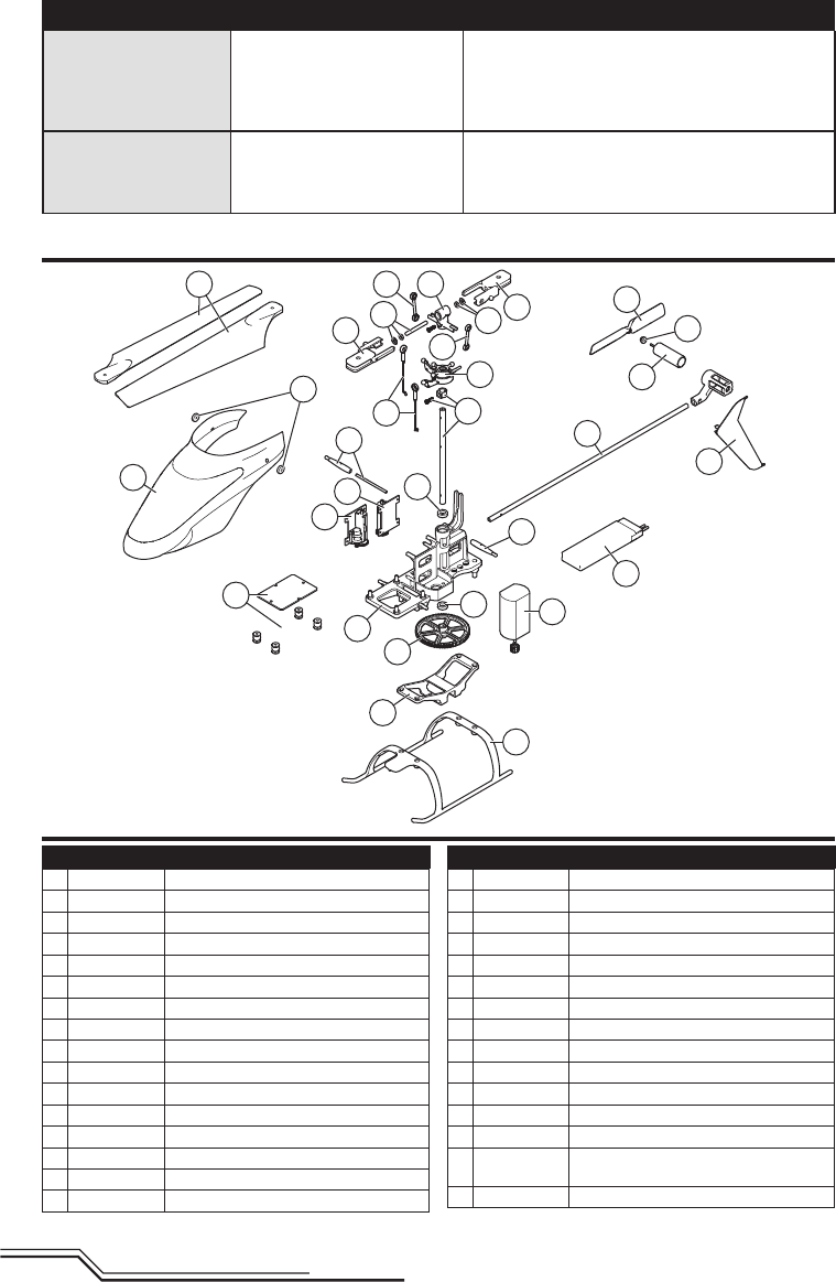
30
DE
1
10
23
3
4
13
26
5
7
8
20
9
25
6
15
16
12
17
24
18
18
19
11 15
22 22
14
14
221
21
Explosionszeichnung
Teileliste
Teil # Beschreibung
BLH4100 120 S RTF
BLH4180 120 S BNF
1 SPMSH2029L Linearservo lang 35mm Kabel
2 SPMSH2030L Linearservo lang 60mm Kabel
3 BLH4101 Blade Hauptplatine
4 BLH4102 Blade Heckauslegerset
5 BLH4103 Blade Hauptmotor
6 BLH4104 Blade Rahmen
7 BLH4105 Blade Rotorwelle
8 BLH4106 Blade Taumelscheibe
9 BLH4107 Blade Kabinenhaube
10 BLH4108 Blade Heckfi nne
11 BLH4111 Blade Hauptrotorblätter
12 BLH4112 Blade Akkufach
13 BLH3117 Blade Heckrotor
14 BLH3705 Blade: Kabinenhaubenhalter
Teil # Beschreibung
15 BLH3115 Blade Anlenkungen Rotorkopf
16 BLH3106 Blade Hauptgetriebe
17 BLH3709 Blade Kufengestell
18 BLH3114 Blade Blattgriffe
19 BLH3108 Blade Servogestänge
20 BLH3112 Blade Hauptrotorkopf
21 BLH3128 Blade Lager Hauptrotorwelle
22 BLH3113 Blade Spindel mit Lagern und O-Ringen
23 BLH3129 Blade 120 SR Heckmotor
24 EFLB5001S25 1S, 500 mAh, 25C LiPo Akku, JST
25 BLH3121 Blade Gummitüllen für die Kabinenhaube
26 BLH3125 Blade Schutzkappe Heckmotor
BLH4109 Blade Schraubenset
EFLRMLP6 E-fl ite MLP6DSM 6CH SAFE Sender 2.4GHz
(nur RTF Version)
EFLC1010 1S, 500 mAh USB LiPo Ladegerät, JST
Problem Mögliche Ursache Lösung
Driftet bei Wind Normal
Das Modell driftet mit dem Wind sollte aber dabei aufrecht bleiben.
Steuern Sie mit der zyklischen Steuerung in die entsprechenden
Richtung um das Modell auf einem Punkt zu halten. Das Modell
muß sich dabei etwas gegen den Wind lehnen sonst wird er wie-
der vom Wind abgetrieben
Schwere Vibrationen Drehende Komponente ist nicht mehr
gewuchtet
Prüfen Sie die Hauptrotorwelle, Heckrotor, Hauptrotorblätter, Rah-
men und Adapter auf Beschädigungen. Ersetzen Sie wenn not-
wendig. Damit die Panikfunktion und die Stabilisierung einwandfrei
funktionieren müssen die Vibrationen minimiert werden