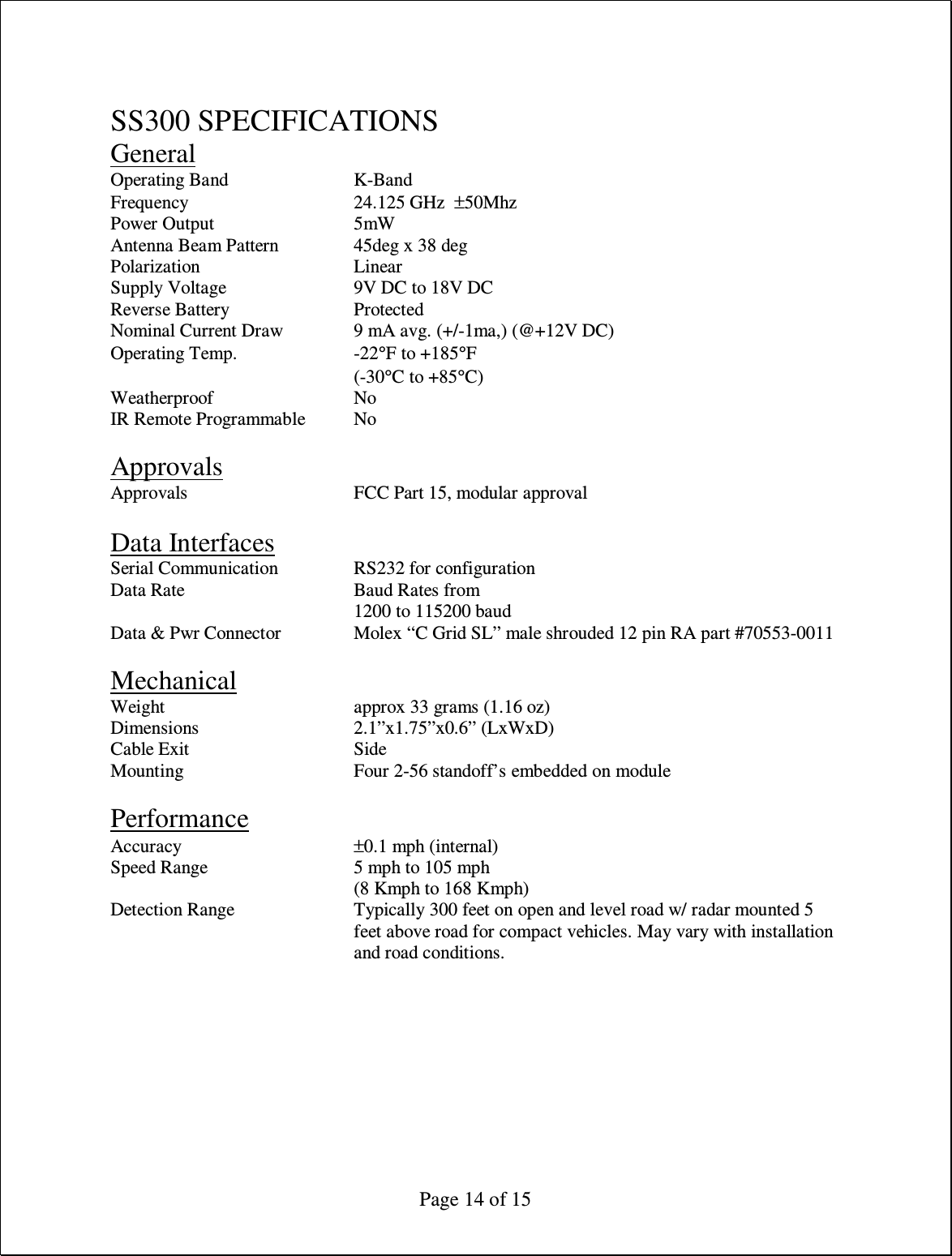
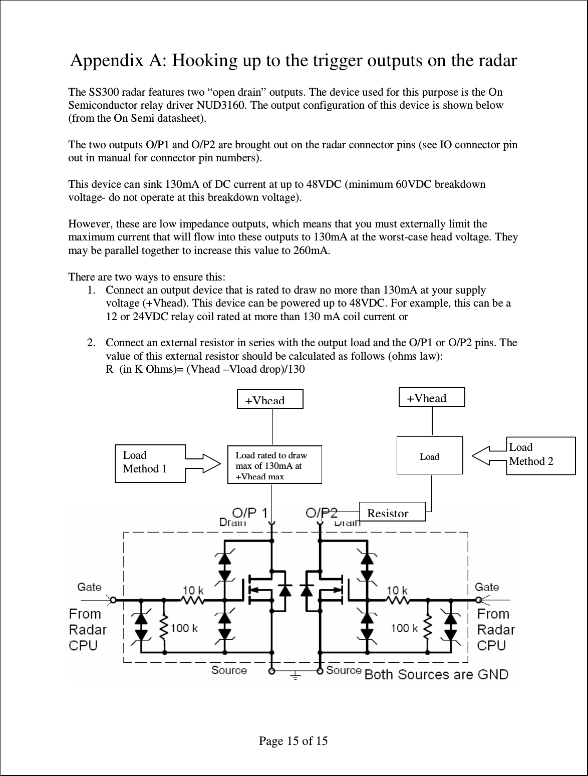
Houston Radar SS300 Doppler Speed Radar User Manual SS300UserManual Rev3

Houston Radar LLC Doppler Speed Radar SS300UserManual Rev3

manual

 Page 1 of 15  Houston Radar LLC  Installation and User Manual For  SS300  K-Band Doppler Speed Sensor                           Houston Radar LLC 13814 Sherburn Manor Dr. Cypress .TX Http://www.Houston-Radar.com Email: sales@Houston-Radar.com Contact: 1-888-602-3111 Rev 3, 20 August 2009
 Page 2 of 15 This device complies with part 15 of the FCC Rules. Operation is subject to the following two conditions: (1) this device may not cause harmful interference, and (2) this device must accept any interference received, including interference that may cause undesired operation.  Changes or modifications not expressly approved by the party responsible for compliance could void the user's authority to operate the equipment.  Any modification or use other than specified in this manual will strictly void the certification to operate the device.  This device carries FCC modular approval and as such is labeled with FCC ID TIASS300. If this label is not visible when the module is installed inside another device, then the outside of the device into which the module is installed must also display a label referring to the enclosed SS300 module. This exterior label can use wording such as the following: “Contains Transmitter Module FCC ID:  TIASS300” or “Contains FCC ID: TIASS300.” Any similar wording that expresses the same meaning may be used.
 Page 3 of 15                                            Note: Specifications may change without notice. Note: Not liable for typographical errors or omissions.
 Page 4 of 15   Table Of Contents   INTRODUCTION.........................................................................................................5 INSTALLATION ..........................................................................................................5 MOUNTING: .................................................................................................................5 DIRECTION POINTING: ..................................................................................................6 RECOMMENDED ENCLOSURE: .......................................................................................6 HOOKUP:......................................................................................................................7 Power Input:............................................................................................................7 Serial Connection:...................................................................................................7 Setting Detection Sensitivity via the ASCII Interface:...............................................7 WIRE SIGNAL DESCRIPTIONS: .......................................................................................9 USE ..............................................................................................................................10 Internal Clock: ......................................................................................................11 Configuring the Unit: ............................................................................................11 Setting Variables in the Radar:..............................................................................12 SS300 SPECIFICATIONS ..........................................................................................14 GENERAL ...................................................................................................................14 APPROVALS................................................................................................................14 DATA INTERFACES .....................................................................................................14 MECHANICAL.............................................................................................................14 PERFORMANCE...........................................................................................................14 APPENDIX A: HOOKING UP TO THE TRIGGER OUTPUTS ON THE RADAR......................................................................................................................................15
 Page 5 of 15  INTRODUCTION  Congratulations on your purchase of the Houston Radar LLC’s directional Doppler speed sensor SS300. This state of the art K-band microwave Doppler speed radar based sensor is specifically designed for the license free battery operated speed-sensing market.  Utilizing the latest in high performance, ultra low power DSP (Digital Signal Processing) technology, you will find that this high quality product meets your exacting standards for performance and reliability.  Some of the highlights of this product include:  FCC approved for your convenience and piece of mind  Unprecedented low power usage of only 9 mA at 12VDC  Unprecedented small size to allow incorporation into virtually any location  Advanced DSP based performance yields consistent performance and speed detection  Typically 300+ feet of pickup distance for incoming vehicles on open and level road  Two trigger outputs capable of handling 130 mA each when vehicle detected  Radar internal software is “bootloader” flash upgradeable in the field  Optional rotary/thumbwheel switch input allows changes to speed threshold  Many radar parameters can be set via serial port input including: o Min/Max speed limit of detection o Speed limit setting for flashing “trigger” output o Sensitivity setting for changing detection range o Serial port settings o Complete radar built in self test  INSTALLATION  Mounting:  The SS300 is supplied in an “open frame” format. It requires a weatherproof enclosure before it may be mounted outside. Alternatively it may be mounted as a component in another product.  The SS300 should be mounted such that the “golden pads” on the front of the unit are vertical as shown in the picture on the front page. The unit may be mounted 90degrees from the suggested optimal mounting. However, in this case, the detection range may be reduced by about 25%.
 Page 6 of 15  Direction Pointing:  The SS00 is directional in nature. It rejects traffic moving away from it and only measures oncoming traffic. If you require the unit to detect outgoing traffic, please contact Houston Radar for a firmware update.   For optimal performance:   Radar should be mounted with the words “NARROW” on the face of the unit either on the top or bottom  Radar should be pointed into the direction of the oncoming traffic.  Radar should be placed along the size of the road to minimize the angle of the oncoming traffic to the radar. o If radar cannot be placed right along the side of the road, it should be pointed at least 100-150 feet up the road into oncoming traffic.  The radar may pickup rotating fans. Avoid pointing it at fans or compressors.  Radar should be mounted at least 3 feet high from the road for optimal performance and at least 5 feet off the ground for maximum pickup distance  Recommended Enclosure:  The radar needs to be enclosed in a weatherproof enclosure for outside use. The following needs to be observed for optimal performance:  1. The front face of the radar (with the golden pads) is the antenna and is the face that must point into traffic. 2. Any cover or window in front of the unit MUST be at least ¼” away from the face. 3. Do NOT spray any conformal (or other) coating, paint or other substance on the antenna. 4. The optimum material to use as a front window is Lexan (Polycarbonate) plastic. 5. The optimum thickness of this polycarbonate window is half wavelength of 24.125Ghz or 3.5mm thick. a. Alternatively a thin window of any plastic material may be used. The maximum thickness in this case should be no more than 1 mm (40 mils). 6. Other plastic materials may be used as a front window, but the optimum thickness will wary with the material’s dielectric constant. Please contact us for details.  Alternatively, you may consider a weatherproof version of SS300 that is available from Houston Radar.
 Page 7 of 15  Hookup:  Power Input:  The SS300 radar should be powered from a nominal 12V DC battery and features industry leading operational power consumption of less than 9mA (average).  There is no other radar in the world that even comes close to this ultra-low power usage.  This operational power translates directly into a longer battery life or gives you an option to power the unit from smaller batteries that would also require smaller solar panels.   Note: The radar employs aggressive power saving measures that include turning off parts of the circuit that are not being used at any instant. To get a true measure of the power usage of the circuit use a multi-meter that has an averaging function. Otherwise you will get current readings that fluctuate from 4 mA to 18 mA.  Serial Connection:  The SS300 features a RS232 interface that is used to configure the unit as explained later in this document.  Setting Detection Sensitivity via the ASCII Interface:  In addition through the supplied PC program interface, the radar also allows ASCII programmatic sensitivity setting.  Over the serial interface, send in ASCII the following commands:  Sensitivity:nn\n and  Sensitivity?\n   In the 1st case it sets the detection sensitivity to "nn" where nn is from 10 to 99 and is a % of the max detection distance (typically about 600 feet but can vary with installation effects and size of the target).  If the sensitivity is set ok, it replies with  OK\n   Note 1: The setting of the sensitivity is written to flash and is NON-volatile. DO NOT write the sensitivity value on a periodic basis (e.g. every second or every minute) (i.e. only change it when the user changes it). The flash has a limited number of write cycles and will wear out with excessive writes!!
 Page 8 of 15 Note 2: A reset is required after setting the sensitivity as the radar will no longer send speeds out (it changes the mode to a different serial interface mode). The regular interface mode is restored when the radar is powered cycled.  No reset is required when using the Windows PC interface.
 Page 9 of 15 Wire Signal Descriptions:  Note 1: See Appendix A for detailed description on how to hookup an external device to be triggered when radar detects incoming objects. Incorrect hookup will result in the output devices being destroyed and will not be covered under warranty.  The SS300 features TWO low impedance outputs that can trigger/turn on an external display/device to bring it out of power saving mode when a vehicle is detected. Both outputs are under radar software control and the typical functionality is to turn both on together when a vehicle is detected. However, if you need different functionality please contact us.  When a vehicle is detected and the speed is above the “LO” speed limit and below the “HI” speed limit both these pins are pulled down to GND and held down to GND as long as a vehicle is detected. These pins are released as soon as the radar detects no further traffic.  These are “open drain” (AKA open collector) outputs capable of sinking 130 mA each. You must limit the current externally to ensure that no more than 130 mA goes into each pin when they turn on. They may be connected in parallel to double the sink capacity to 260 mA. The device providing this functionality on the radar board is the ON-Semi “NUD3160” relay driver. Please refer to the datasheet for this device on detailed operating characteristics for these trigger outputs.   Connector Pin # Signal Name Direction (wrt Radar) Description 1  GND  PWR  Radar GND (battery “–“ terminal) 2  N/C  N/C  Do not connect 3  I/O0  I/O  Reserved for future use 4  I/O1  I/O  Reserved for future use 5  I/O2  I/O  Reserved for future use 6  I/O3  I/O  Reserved for future use 7  Trig O/P 1  Output  “Open Drain Output 1”. See Note 1. 8  Trig O/P 2  Output  “Open Drain Output 2”. See Note 1. 9  RS232 TX  Output  RS232 Transmit Signal from radar 10  RS232 RX  Input  RS232 Receive Signal into radar 11  VCC  PWR  +9.5 to +18VDC Power Supply 12  GND  PWR  Radar GND (battery “-“ terminal)
 Page 10 of 15  USE  Turn on the power to the SS300 to make it operational. No other action is required. The radar will trigger OUT 1 and OUT 2 open collector outputs whenever it detects a vehicle that is above the programmed lower speed limit (the “LO” value) and below the programmed high limit (the “HI” value). The default limits are set at 5mph (kph) and 99mph (kph) at the factory (the values in brackets apply if units are set to KPH).  Using the provided configuration Windows software and via the serial port, program the high limit to de-assert the trigger outputs above this limit. If you do not wish an upper detection limit, set this value to 159. This will ensure that the upper limit is never reached regardless if the units are set to MPH or KPH.  Set the “LO” variable to set the lower detection speed limit. The outputs will be de-asserted for vehicles below this speed limit. The lowest value this may be set is 3 MPH (5KPH).  Green LED flashes on front at 1/3 Hz (1/6 duty cycle) rate when radar is running giving a visual OK signal.
 Page 11 of 15  Internal Clock:  The radar has a built in clock/calendar function. At the moment this is not used by the firmware. However future functionality may be added that uses this functionality.  The radar does not feature a clock backup battery. So power must remain connected to the radar for the clock to keep time.    Configuring the Unit:  The unit’s internal parameters may be configured by connecting the radar’s RS232 port to a PC’s RS232 serial port and using the Houston Radar Advanced Stats Analyzer program’s configuration screen as described here.  The following internal “variables” may be set. Their functions are described below:  Radar Configuration Variable Name Description RS  Sets the RS232 serial port’s baud rate and output format. Do not change this value unless a value is provided by Houston Radar. UN  Sets the internal speed units of the radar. All LO, SP & HI speeds are interpreted to be in this units. 0 = MPH 1 = KPH LO  Low speed cutoff. Vehicles are not detected below this speed. Minimum value is 3. Should be set to be less than HI. Speeds above this limit trigger the O/P1 and O/P2 outputs. HI  High speed cutoff. Vehicles are not detected above this speed. Maximum value is 159. Should be set higher than LO speed. SP  Flashing speed limit. Any speed higher than this value “flashes” the trigger output at 2/3 duty cycle, 1Hz. ST  Target detection sensitivity. Valid values are from 10 to 99 and are a percentage of max range. So a value of 50 would yield about 150 feet detection. Note: This is not a range setting but detection sensitivity. Thus if large vehicles are being detected at 400 feet, a value of 500 will make them detect at approx 200 feet. SF  1 = Select Fastest Target if multiple targets are detected on the road 0 = Select Strongest Target if multiple targets are detected on the road KY  Reserved. Do not set unless value provided by Houston Radar
 Page 12 of 15 Setting Variables in the Radar:  1. Install the Houston Radar Advanced Stats Analyzer Windows program on a Windows 2000, XP or Vista computer. 2. Connect the radar RS232 port to the PC’s RS232 serial port. If the PC does not have a serial port you may buy a USB serial converter dongle (from BestBuy, Radioshack or any Internet store). 3. Power up the radar. Ensure the green LED on the front flashes at a 1/3Hz 1/6 duty cycle rate. 4. Start the Houston Radar Stats Analyzer program 5. Click on Start->Connect to Radar… 6. Click on “Connect” button. 7. Ensure you see a “Radar found on COM” message. The COM # will depend on your computer 8. Click on OK. Now you are ready to configure the radar. 9. To configure the LO, SP & HI limits, click on “Radar Limits” menu bar item. The three fields show the current values of the three variables. Change the variables to the desired values and click on “Save”. 10. To configure any other variable, click on “Advanced->Radar Configuration”. In the window that comes up, enter the two letter variable name in the “Variable” field. Enter its value in the “Value” field and click on “Set Variable” button.
 Page 13 of 15 Set Serial Baud Rate:  The supplied Windows configuration program can auto detect the baud rate of the radar serial port. However if you wish to communicate with the radar from your electronics, the radar serial port may be configured to different baud rates.    Baud Rate (bps) # Data Bits # Stop Bits Parity “RS” variable value 1200  7  1  Even  10 1200  7  1  Odd  11 1200  7  1  None  12 1200  8  1  None  13          2400  7  1  Even  20 2400  7  1  Odd  21 2400  7  1  None  22 2400  8  1  None  23          9600  7  1  Even  30 9600  7  1  Odd  31 9600  7  1  None  32 9600  8  1  None  33          115200  7  1  Even  40 115200  7  1  Odd  41 115200  7  1  None  42 115200  8  1  None  43          19200  7  1  Even  50 19200  7  1  Odd  51 19200  7  1  None  52 19200  8  1  None  53 Note: The radar has other baud rates and output format options that can be set via the serial port. Contact Houston Radar if one of the above is not suitable for your requirements.
 Page 14 of 15  SS300 SPECIFICATIONS General Operating Band     K-Band Frequency      24.125 GHz  ±50Mhz Power Output      5mW Antenna Beam Pattern    45deg x 38 deg       Polarization      Linear Supply Voltage     9V DC to 18V DC Reverse Battery     Protected Nominal Current Draw    9 mA avg. (+/-1ma,) (@+12V DC) Operating Temp.    -22°F to +185°F         (-30°C to +85°C) Weatherproof      No IR Remote Programmable  No  Approvals Approvals      FCC Part 15, modular approval  Data Interfaces Serial Communication    RS232 for configuration Data Rate      Baud Rates from 1200 to 115200 baud Data & Pwr Connector    Molex “C Grid SL” male shrouded 12 pin RA part #70553-0011      Mechanical Weight       approx 33 grams (1.16 oz) Dimensions      2.1”x1.75”x0.6” (LxWxD) Cable Exit      Side Mounting      Four 2-56 standoff’s embedded on module  Performance Accuracy      ±0.1 mph (internal) Speed Range      5 mph to 105 mph         (8 Kmph to 168 Kmph)  Detection Range  Typically 300 feet on open and level road w/ radar mounted 5 feet above road for compact vehicles. May vary with installation and road conditions.
 Page 15 of 15 Appendix A: Hooking up to the trigger outputs on the radar  The SS300 radar features two “open drain” outputs. The device used for this purpose is the On Semiconductor relay driver NUD3160. The output configuration of this device is shown below (from the On Semi datasheet).  The two outputs O/P1 and O/P2 are brought out on the radar connector pins (see IO connector pin out in manual for connector pin numbers).  This device can sink 130mA of DC current at up to 48VDC (minimum 60VDC breakdown voltage- do not operate at this breakdown voltage).  However, these are low impedance outputs, which means that you must externally limit the maximum current that will flow into these outputs to 130mA at the worst-case head voltage. They may be parallel together to increase this value to 260mA.  There are two ways to ensure this: 1. Connect an output device that is rated to draw no more than 130mA at your supply voltage (+Vhead). This device can be powered up to 48VDC. For example, this can be a 12 or 24VDC relay coil rated at more than 130 mA coil current or  2. Connect an external resistor in series with the output load and the O/P1 or O/P2 pins. The value of this external resistor should be calculated as follows (ohms law): R  (in K Ohms)= (Vhead –Vload drop)/130           Load rated to draw max of 130mA at +Vhead max +Vhead   Load +Vhead  Resistor Load Method 1 Load Method 2

Navigation menu