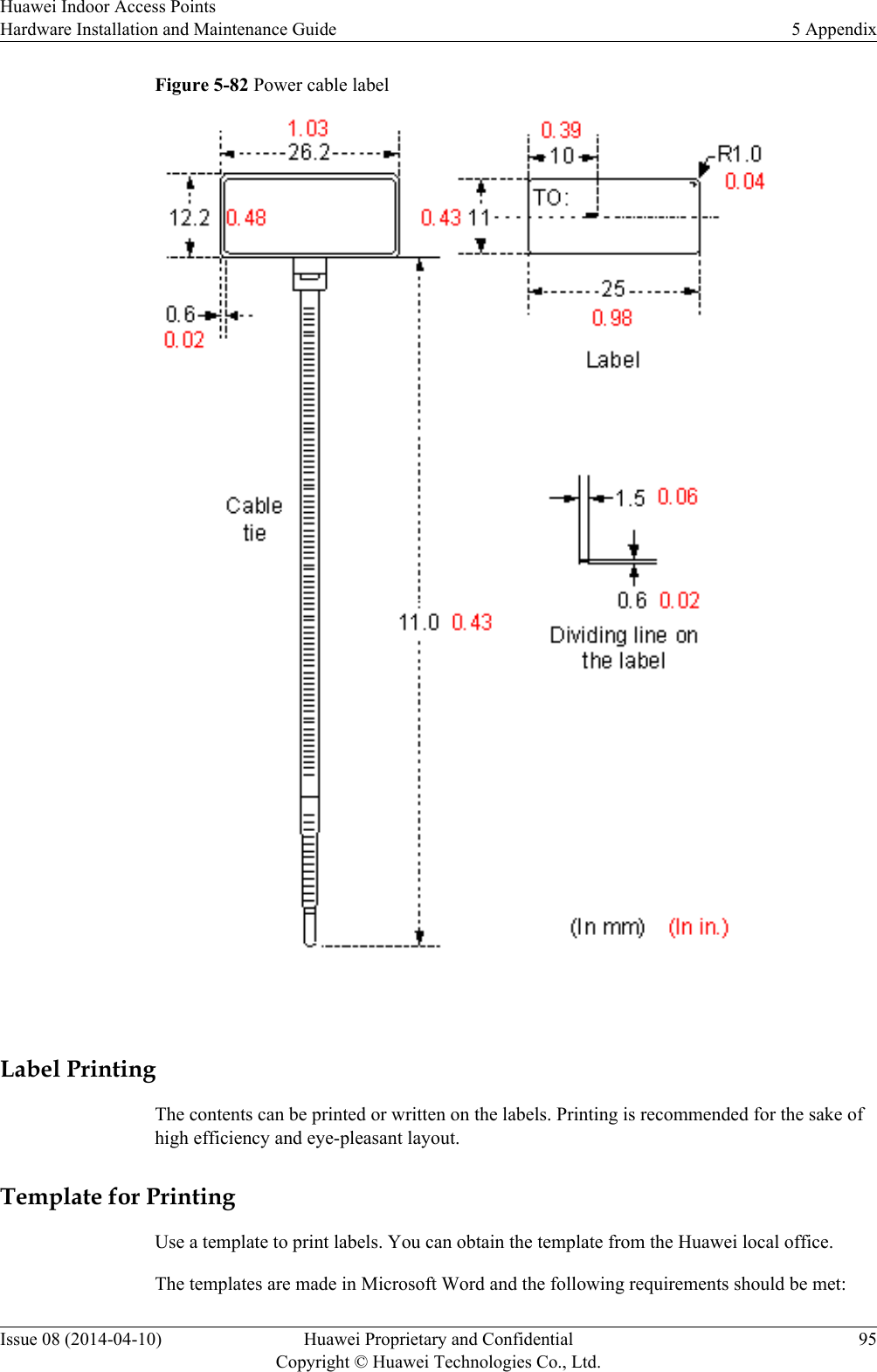
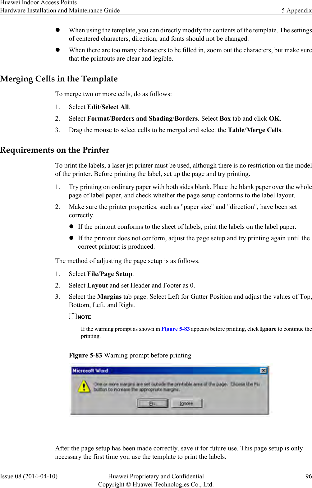
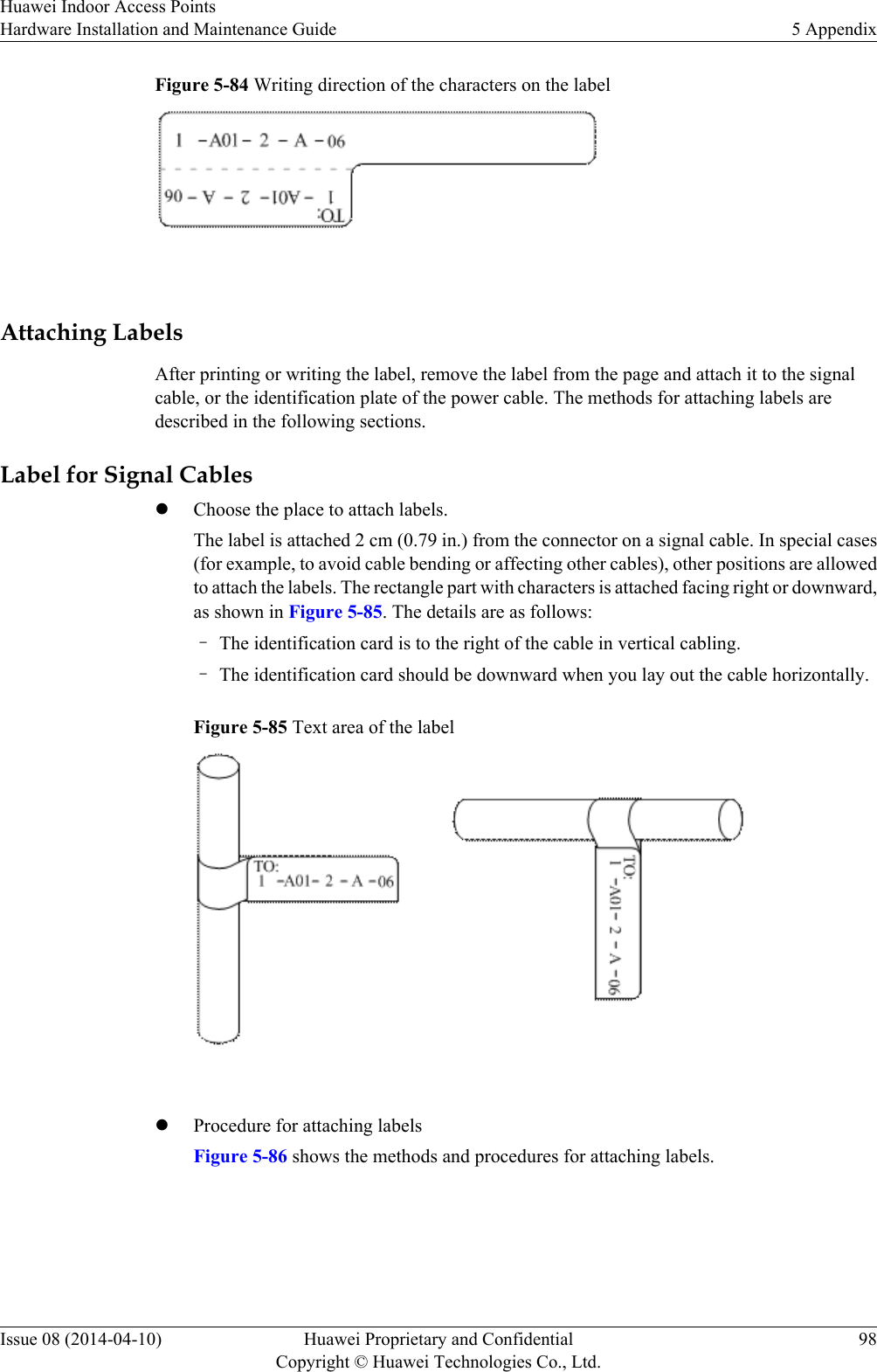
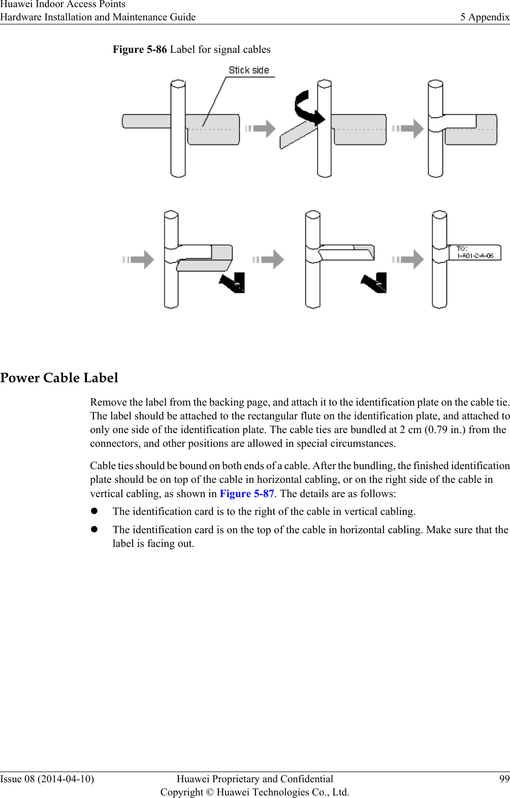
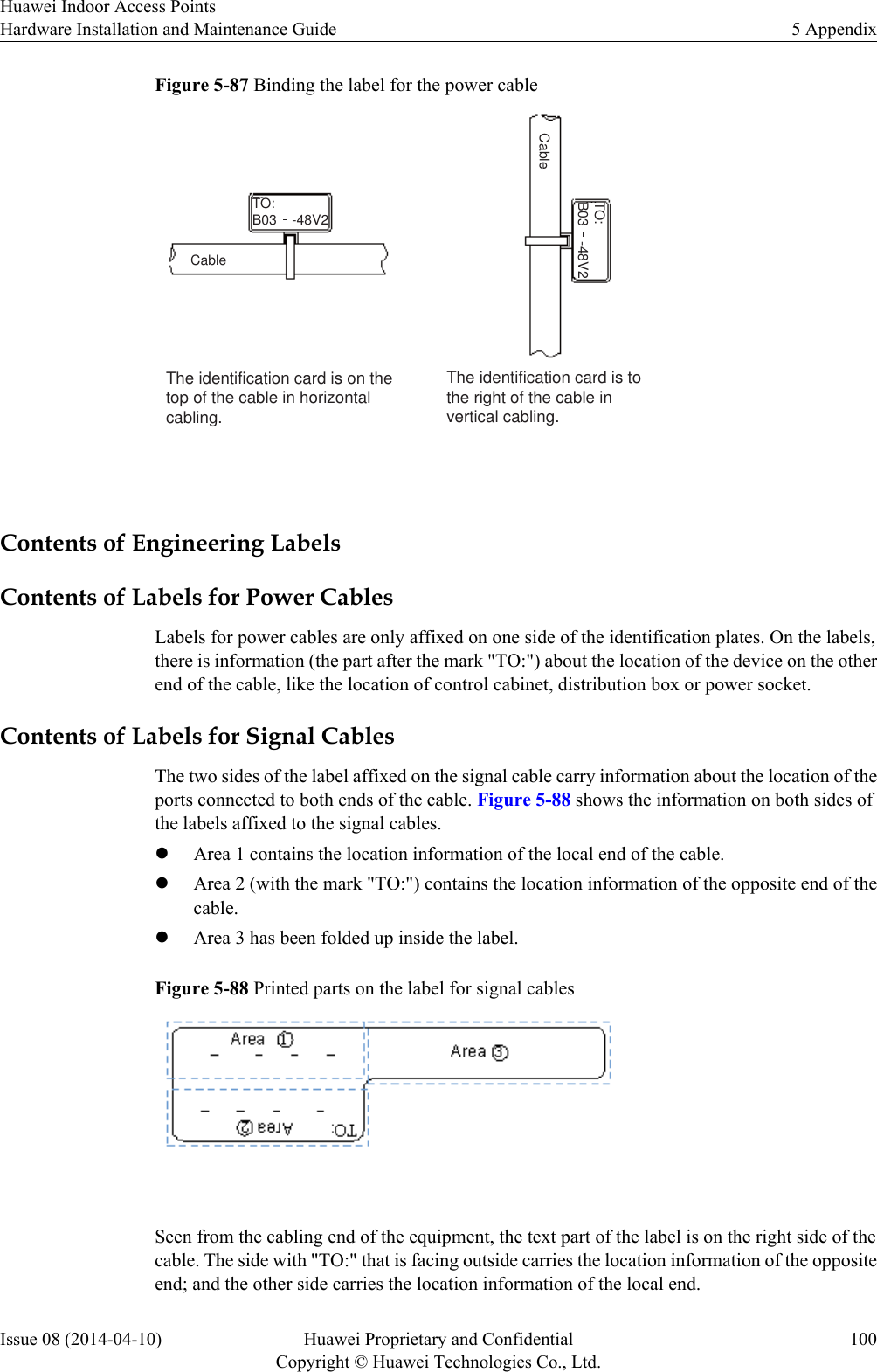
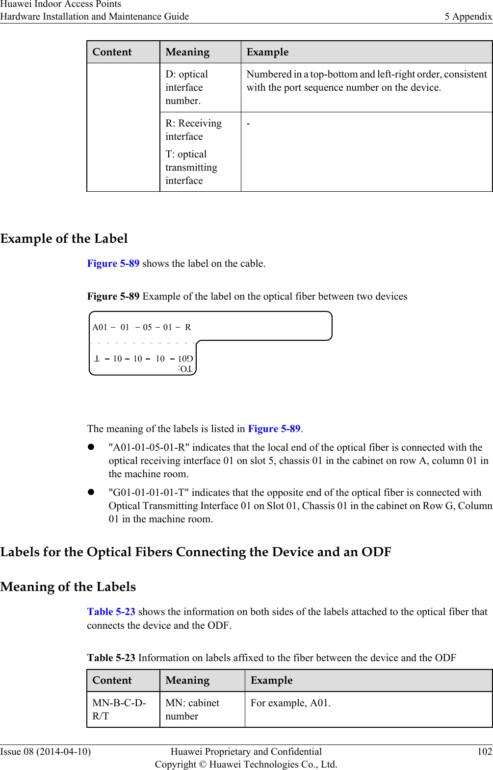
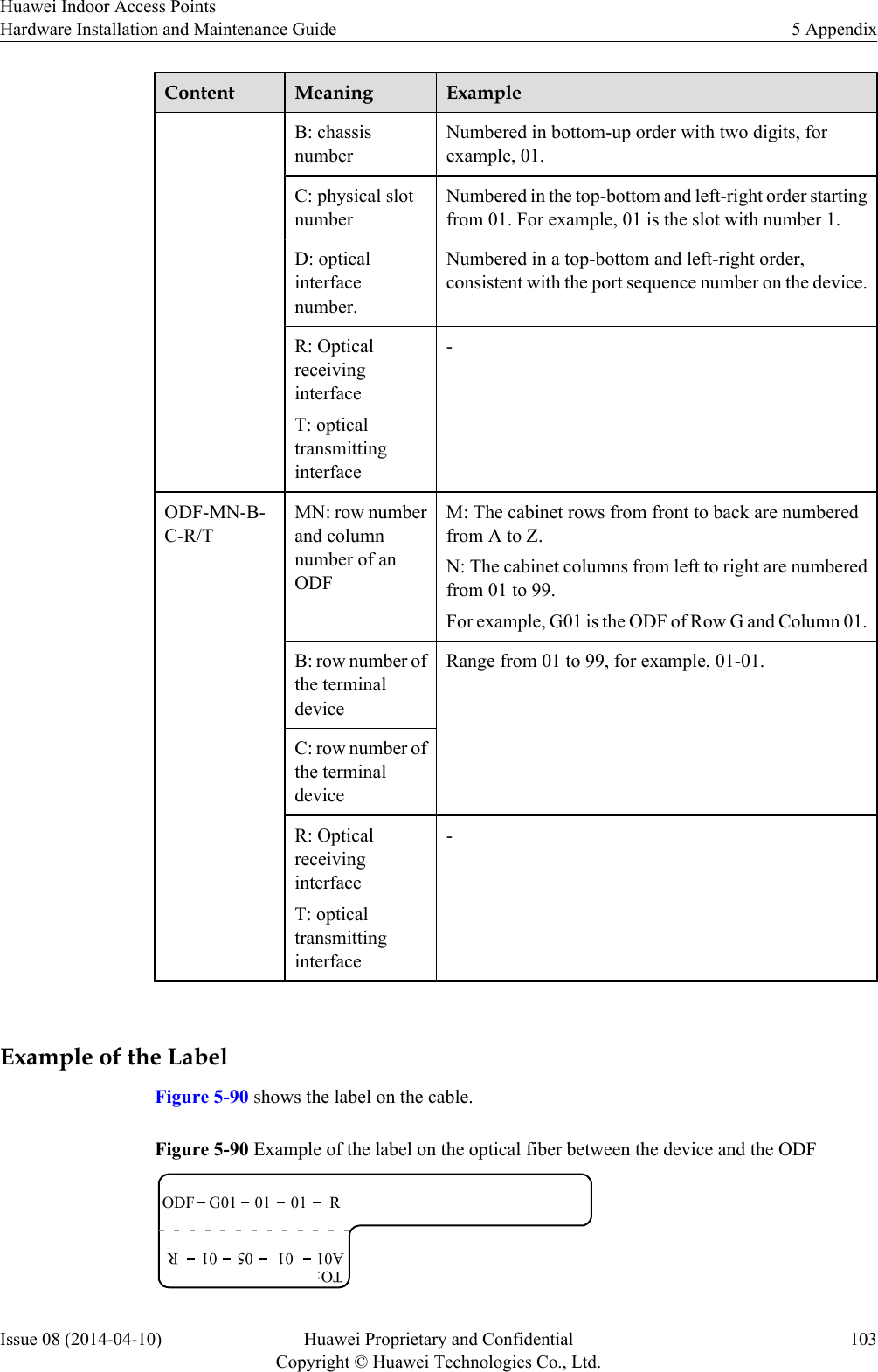
Huawei Technologies AP505130DN Wireless LAN Access Point User Manual Hardware Installation and Maintenance Guide

Huawei Technologies Co.,Ltd Wireless LAN Access Point Hardware Installation and Maintenance Guide

User manual-2

Huawei Indoor Access PointsHardware Installation andMaintenance GuideIssue 08Date 2014-04-10HUAWEI TECHNOLOGIES CO., LTD.
  Copyright © Huawei Technologies Co., Ltd. 2014. All rights reserved.No part of this document may be reproduced or transmitted in any form or by any means without prior writtenconsent of Huawei Technologies Co., Ltd. Trademarks and Permissions and other Huawei trademarks are trademarks of Huawei Technologies Co., Ltd.All other trademarks and trade names mentioned in this document are the property of their respective holders. NoticeThe purchased products, services and features are stipulated by the contract made between Huawei and thecustomer. All or part of the products, services and features described in this document may not be within thepurchase scope or the usage scope. Unless otherwise specified in the contract, all statements, information,and recommendations in this document are provided "AS IS" without warranties, guarantees or representationsof any kind, either express or implied.The information in this document is subject to change without notice. Every effort has been made in thepreparation of this document to ensure accuracy of the contents, but all statements, information, andrecommendations in this document do not constitute a warranty of any kind, express or implied.        Huawei Technologies Co., Ltd.Address: Huawei Industrial BaseBantian, LonggangShenzhen 518129People's Republic of ChinaWebsite: http://enterprise.huawei.comIssue 08 (2014-04-10) Huawei Proprietary and ConfidentialCopyright © Huawei Technologies Co., Ltd.i
About This DocumentIntended AudienceThis document describes hardware features of indoor APs and provides basic installationmethods.This document is intended for:lNetwork planning engineerslHardware installation engineerslCommissioning engineerslOnsite maintenance engineerslSystem maintenance engineersSymbol ConventionsThe symbols that may be found in this document are defined as follows.Symbol DescriptionIndicates an imminently hazardous situationwhich, if not avoided, will result in death orserious injury.Indicates a potentially hazardous situationwhich, if not avoided, could result in death orserious injury.Indicates a potentially hazardous situationwhich, if not avoided, may result in minor ormoderate injury.Indicates a potentially hazardous situationwhich, if not avoided, could result inequipment damage, data loss, performancedeterioration, or unanticipated results.NOTICE is used to address practices notrelated to personal injury.Huawei Indoor Access PointsHardware Installation and Maintenance Guide About This DocumentIssue 08 (2014-04-10) Huawei Proprietary and ConfidentialCopyright © Huawei Technologies Co., Ltd.ii
Symbol DescriptionNOTECalls attention to important information, bestpractices and tips.NOTE is used to address information notrelated to personal injury, equipment damage,and environment deterioration. Change HistoryChanges between document issues are cumulative. The latest document issue contains allchanges made in previous issues.Issue 08 (2013-04-10)This version has the following updates:The following information is added:lAP5030DN and AP5130DN installation guidelNote: The network cable cannot exceed 100 meters.Issue 07 (2014-01-15)This version has the following updates:Optimized the manual.Issue 06 (2013-09-30)This version has the following updates:The following information is modified:lAP's default IP address and login passwordIssue 05 (2013-06-29)This version has the following updates:The following information is modified:lFigure for converting SMA connectors to type—N connectorsIssue 04 (2013-04-30)This version has the following updates:The following information is modified:lFigure of the sheet metal mounting brackets delivered with APsHuawei Indoor Access PointsHardware Installation and Maintenance Guide About This DocumentIssue 08 (2014-04-10) Huawei Proprietary and ConfidentialCopyright © Huawei Technologies Co., Ltd.iii
Issue 03 (2013-01-30)This version has the following updates:The following information is added:lDescriptions about power adapters delivered with APslSection: Removing an APIssue 02 (2012-12-31)This version has the following updates:The following information is added:lPower adapter cable connection figureIssue 01 (2012-10-31)Initial commercial releaseHuawei Indoor Access PointsHardware Installation and Maintenance Guide About This DocumentIssue 08 (2014-04-10) Huawei Proprietary and ConfidentialCopyright © Huawei Technologies Co., Ltd.iv
ContentsAbout This Document.....................................................................................................................ii1 Indoor AP Overview.....................................................................................................................11.1 Device Structure.............................................................................................................................................................21.2 Indicator Description......................................................................................................................................................41.3 Basic Specifications........................................................................................................................................................72 AP Installation.............................................................................................................................112.1 Preparing for Installation..............................................................................................................................................122.2 Installation Flowchart...................................................................................................................................................132.3 Unpacking the Equipment............................................................................................................................................142.4 Determining the Installation Position...........................................................................................................................152.5 Installing the AP...........................................................................................................................................................162.5.1 Wall Mounting...........................................................................................................................................................172.5.2 Ceiling Mounting.......................................................................................................................................................192.5.3 T-rail Mounting.........................................................................................................................................................202.5.4 Removing an AP........................................................................................................................................................212.6 Connecting Cables........................................................................................................................................................222.7 Installing the Security Lock..........................................................................................................................................262.8 Checking the AP After Installation..............................................................................................................................262.9 Powering on the AP......................................................................................................................................................273 Logging In to the AP...................................................................................................................283.1 Logging In to the AP Through the Console Port..........................................................................................................293.2 Logging In to the AP Using Telnet..............................................................................................................................313.3 Logging In to the AP Using a Web Client....................................................................................................................314 Hardware Failures.......................................................................................................................334.1 An device Fails to Be Powered On...............................................................................................................................344.2 An Optical Interface Cannot Turn Up..........................................................................................................................345 Appendix.......................................................................................................................................365.1 On-site Cable Assembly and Installation.....................................................................................................................375.1.1 Cable Assembly Precautions.....................................................................................................................................375.1.2 Assembling Power Cables.........................................................................................................................................38Huawei Indoor Access PointsHardware Installation and Maintenance Guide ContentsIssue 08 (2014-04-10) Huawei Proprietary and ConfidentialCopyright © Huawei Technologies Co., Ltd.v
5.1.3 Assembling Ethernet Cables......................................................................................................................................465.1.4 Installing Cable Accessories......................................................................................................................................605.1.5 Replacing the Mold of the Crimping Pliers...............................................................................................................765.2 Environmental Requirements for Device Operation....................................................................................................795.2.1 Environmental Requirements for an Equipment Room............................................................................................795.2.2 Requirements for Power Supply................................................................................................................................875.3 Equipment Grounding Specifications...........................................................................................................................905.3.1 General Grounding Specifications.............................................................................................................................905.3.2 Grounding Specifications for an Equipment Room..................................................................................................905.3.3 Grounding Specifications for Devices.......................................................................................................................905.3.4 Grounding Specifications for Communications Power Supply.................................................................................915.3.5 Grounding Specifications for Signal Cables.............................................................................................................925.3.6 Specifications for Laying Out Grounding Cables.....................................................................................................925.4 Engineering Labels for Cables.....................................................................................................................................935.4.1 Introduction to Labels................................................................................................................................................935.4.2 Engineering Labels for Optical Fibers.....................................................................................................................1015.4.3 Engineering Labels for Network Cables.................................................................................................................1045.4.4 Engineering Labels for User Cables........................................................................................................................1055.4.5 Engineering Labels for Power Cables.....................................................................................................................1065.5 Guide to Using Optical Modules................................................................................................................................1095.6 Fault Tag.....................................................................................................................................................................112Huawei Indoor Access PointsHardware Installation and Maintenance Guide ContentsIssue 08 (2014-04-10) Huawei Proprietary and ConfidentialCopyright © Huawei Technologies Co., Ltd.vi
1 Indoor AP OverviewAbout This ChapterHuawei indoor wireless LAN access points (APs) include the following models: AP3010DN-AGN, AP5010DN-AGN, AP5010SN-GN, AP5030DN, and AP5130DN, AP6010DN-AGN,AP6010SN-GN, AP6310SN-GN, AP7110DN-AGN, AP7110SN-GN. They providecomprehensive service support capabilities and feature high reliability, high security, simplenetwork deployment, automatic AC discovery and configuration, and real-time managementand maintenance, meeting indoor deployment requirements.Huawei indoor APs are especially applicable to places with simple building structure, small size,dense users, and high capacity demands, such as small-size conference rooms, bars, and leisurecenters. They can be flexibly deployed according to surrounding environment.1.1 Device Structure1.2 Indicator Description1.3 Basic SpecificationsHuawei Indoor Access PointsHardware Installation and Maintenance Guide 1 Indoor AP OverviewIssue 08 (2014-04-10) Huawei Proprietary and ConfidentialCopyright © Huawei Technologies Co., Ltd.1
1.1 Device StructureFigures in Table 1-1 show the appearance of indoor APs.CAUTIONThere is a scald warning label attached on the device, warning you not to touch the device afterthe device has been operating for a long time.Table 1-1 Appearance of indoor APsProduct Model AppearanceAP3010DN-AGNAP5010DN-AGNAP5010SN-GNAP6010DN-AGNAP6010SN-GN12367ConsoleETH/PoEDefaultDC 12VAP5030DN265 74 1Console GE1 GE0/PoE DC 12VHuawei Indoor Access PointsHardware Installation and Maintenance Guide 1 Indoor AP OverviewIssue 08 (2014-04-10) Huawei Proprietary and ConfidentialCopyright © Huawei Technologies Co., Ltd.2
Product Model AppearanceAP5130DN265 7104 1Console GE1 GE0/PoE DC 12VAP6310SN-GN2.4G Console ETH/PoE Default DC 12V8 3 1116 2AP7110DN-AGN9 3 1 8211 6 7Console ETH/PoE Default DC 12VAP7110SN-GNConsole ETH/PoE DC 12VDefault11 6 2 73 1 8 Table 1-2 describes interfaces on indoor APs.Huawei Indoor Access PointsHardware Installation and Maintenance Guide 1 Indoor AP OverviewIssue 08 (2014-04-10) Huawei Proprietary and ConfidentialCopyright © Huawei Technologies Co., Ltd.3
Table 1-2 Interfaces on indoor APsNo. Name Description1DC 12 V DC power socket: connects a 12 V poweradapter to the AP.2 Default Reset button: restores factory settings if youhold down the button more than 3s.3 ETH/PoE 10/100/1000M bit/s interface: connects to thewired Ethernet. The interface can connect toa PoE power supply to provide power for theAP.4 GE1 10/100/1000M bit/s interface: connects to thewired Ethernet.5 GE0/PoE 10/100/1000M bit/s interface: connects to thewired Ethernet. The interface can connect toa PoE power supply to provide power for theAP.6 Console Console interface: connects to a maintenanceterminal for AP configuration andmanagement.7 Security slot Connects to a security lock.8 2.4 GHz antenna port Connects a 2.4 GHz antenna to the AP.9 5 GHz antenna port Connects a 5 GHz antenna to the AP.10 Dual-band antennaportConnects a dual-band antenna to the AP.11 Device ground screw Connects a ground cable to the AP. 1.2 Indicator DescriptionIndoor AP series products provide a single indicator or multiple indicators.lThe AP3010DN-AGN, AP5010DN-AGN, AP5010SN-GN, AP5030DN, AP5130DN,AP6010DN-AGN, and AP6010SN-GN provide only a single indicator.lThe AP6310SN-GN, AP7110DN-AGN, and AP7110SN-GN provide multiple indicators:SYS indicator, Link indicator, and Wireless indicator.The following table describes indicators on indoor APs.Huawei Indoor Access PointsHardware Installation and Maintenance Guide 1 Indoor AP OverviewIssue 08 (2014-04-10) Huawei Proprietary and ConfidentialCopyright © Huawei Technologies Co., Ltd.4
NOTElIndicator colors may vary slightly at different temperature.lAfter a Fit AP is powered on, you can run the led off command on the AC to turn off all AP indicators.To restore the indicators to normal working status, run the led on command. Indicators on a Fat APcannot be turned off using the led off command.Single indicator and SYS indicatorTable 1-3 Descriptions about the single indicator and SYS indicatorType Color Status DescriptionDefaultstatus afterpower-onGreen Steady on The AP is just powered on and the software is notstarted yet.SoftwarestartupstatusGreen Steady onafterblinkingonceAfter the system is reset and starts uploading thesoftware, the indicator blinks green once. Until thesoftware is uploaded and started, the indicatorremains steady green.RunningstatusGreen Blinkingonce every2s (0.5 Hz)lThe system is running properly, the Ethernetconnection is normal, and STAs are associatedwith the AP.lThe system enters the Uboot CLI.Blinkingonce every5s (0.2 Hz)The system is running properly, the Ethernetconnection is normal, and no STA is associated withthe AP. The system is in low power consumptionstate.Alarm Green Blinkingonce every0.25s (4Hz)lThe software is being upgraded.lAfter the software is uploaded and started, the APworking in Fit AP mode requests to go online onthe AC and maintains this state until it goesonline successfully on the AC (before theCAPWAP link is established).lThe AP working in Fit AP mode fails to go onlineon the AC (the CAPWAP link disconnects).Fault Red Steady on A fault that affects services has occurred, such as aDRAM detection failure or system software loadingfailure. The fault cannot be automatically rectifiedand must be rectified manually. Huawei Indoor Access PointsHardware Installation and Maintenance Guide 1 Indoor AP OverviewIssue 08 (2014-04-10) Huawei Proprietary and ConfidentialCopyright © Huawei Technologies Co., Ltd.5
Link indicatorTable 1-4 Descriptions about the Link indicatorType Color Status DescriptionLINK Green Steady on The system is running properly, the Ethernetconnection is normal, and no data is beingtransmitted.ACT Green Blinking The system is running properly, the Ethernetconnection is normal, and the AP is transmittingdata. The indicator blinks more quickly when moredata is being transmitted. Wireless indicatorTable 1-5 Traffic volume indicatorColor Status DescriptionYellow/green Off Radios are disabled, and no STA is connectedto the AP.Yellow/green Steady on The AP has STAs connected to the 2.4 GHzradio or 5 GHz radio, but no data is beingtransmitted.Green Blinking The AP has STAs connected to the 2.4 GHzradio and is transmitting data. The indicatorblinks more quickly when more data is beingtransmitted.Yellow Blinking The AP has STAs connected to the 5 GHzradio and is transmitting data. The indicatorblinks more quickly when more data is beingtransmitted.Yellow/green BlinkingalternativelyThe AP has STAs connected to both the 2.4GHz radio and 5 GHz radio. The indicatorblinks more quickly when more data is beingtransmitted. Table 1-6 Wireless bridge indicatorColor Status DescriptionYellow/green Off The AP is not transmitting or receiving dataor the signal strength is extremely low.Huawei Indoor Access PointsHardware Installation and Maintenance Guide 1 Indoor AP OverviewIssue 08 (2014-04-10) Huawei Proprietary and ConfidentialCopyright © Huawei Technologies Co., Ltd.6
Color Status DescriptionSteady on The AP is transmitting or receiving datanormally, and the signal strength is high.Blinking green onceevery 0.25 seconds (4Hz)The AP is transmitting or receiving datanormally, and the signal strength is medium.Blinking once every2s (0.5 Hz)The AP is transmitting or receiving datanormally, and the signal strength is low. NOTEWhen the WDS/mesh function is enabled on an AP, the blinking frequency of its Wireless LED indicatesthe receive signal strength on the WDS/mesh connection by default. After you connect an AP to a WDS/mesh network, you can run the wifi-light { signal-strength | traffic } command on the AC to make theWireless LED blinking frequency indicate receive signal strength or service traffic rate.lwifi-light signal-strength:lIf the mesh function is enabled on the AP, the blinking frequency of the Wireless LED reflectsthe weakest signal strength of all neighboring APs.lIf WDS is enabled on an AP, the blinking frequency of the Wireless LED reflects the strengthof signals received from a WDS AP.lIf the AP works in leaf mode, the blinking frequency of the Wireless LED reflects the strengthof signals received from a middle AP.lIf the AP works in middle mode, the blinking frequency of the Wireless LED reflects thestrength of signals received from a root AP.lIf the AP works in root mode, the blinking frequency of the Wireless LED reflects the weakestsignal strength of middle APs.lwifi-light traffic: allows the Wireless LED to reflect the service traffic volume on the radio.The Fat AP does not support WDS/Mesh functions; therefore, the Wireless indicator of the Fat AP doesnot indicate the signal strength.The AP6310SN-GN does not support WDS/mesh functions; therefore, the Wireless indicator of theAP6310SN-GN does not indicate the signal strength.1.3 Basic SpecificationsTable 1-7 Basic specifications of the AP3010DN-AGN, AP5010SN-GN, AP5010DN-AGN,AP6010DN-AGN, and AP6010SN-GNItem DescriptionTechnicalspecificationsDimensions (H x W xD)50 mm x 180 mm x 180 mmWeight 0.4 kgSystem memory l256 MB DDR2l32 MB flash memoryHuawei Indoor Access PointsHardware Installation and Maintenance Guide 1 Indoor AP OverviewIssue 08 (2014-04-10) Huawei Proprietary and ConfidentialCopyright © Huawei Technologies Co., Ltd.7
Item DescriptionPower specifications Power input lDC 12 V ± 10%lPoE power supply: -48 V DC (incompliance with IEEE 802.3af/at)NOTEThe AP6010DN-AGN and AP6010SN-GN cannotuse the PoE power supply and DC power supplysimultaneously.Maximum powerconsumptionlAP3010DN-AGN: 9.5 WlAP5010DN-AGN: 9.5 WlAP5010SN-GN: 6.0 WlAP6010DN-AGN: 10.2 WlAP6010SN-GN: 6.5 WNOTEThe actual maximum power consumption dependson local laws and regulations.EnvironmentspecificationsOperatingtemperature-10°C to +50°CStorage temperature -40°C to +70°COperating humidity 5% to 95% (non-condensing)Waterproof grade IP31Altitude -60 m to 4000 mAtmosphericpressure70 kPa to 106 kPa Table 1-8 Basic specifications of the AP5030DN and AP5130DNItem DescriptionTechnicalspecificationsDimensions (H x W xD)53 mm x 220 mm x 220 mmWeight 1.0 kgSystem memory l256 MB DDR2l32 MB flash memoryPower specifications Power input lDC 12 V ± 10%lPoE power: -48 V DC (in compliance withIEEE 802.3af/at)Huawei Indoor Access PointsHardware Installation and Maintenance Guide 1 Indoor AP OverviewIssue 08 (2014-04-10) Huawei Proprietary and ConfidentialCopyright © Huawei Technologies Co., Ltd.8
Item DescriptionMaximum powerconsumption13 WNOTEThe actual maximum power consumption dependson local laws and regulations.EnvironmentspecificationsOperatingtemperature-10°C to +50°CStorage temperature -40°C to +70°COperating humidity 5% to 95% (non-condensing)Waterproof grade IP41Altitude -60 m to 4000 mAtmosphericpressure70 kPa to 106 kPa Table 1-9 Basic specifications of the AP6310SN-GNItem DescriptionTechnicalspecificationsDimensions (H x W xD)35 mm x 150 mm x 130 mmWeight 0.6 kgSystem memory l128 MB DDR2l32 MB flash memoryPower specifications Power input lDC 12 V ± 10%lPoE power supply: -48 V DC (incompliance with IEEE 802.3af/at)NOTEThe AP6310SN-GN cannot use the PoE powersupply and DC power supply simultaneously.Maximum powerconsumption8.3 WNOTEThe actual maximum power consumption dependson local laws and regulations.EnvironmentspecificationsOperatingtemperature-10°C to +50°CStorage temperature -40°C to +70°COperating humidity 5% to 95% (non-condensing)Waterproof grade IP31Huawei Indoor Access PointsHardware Installation and Maintenance Guide 1 Indoor AP OverviewIssue 08 (2014-04-10) Huawei Proprietary and ConfidentialCopyright © Huawei Technologies Co., Ltd.9
Item DescriptionAltitude -60 m to 4000 mAtmosphericpressure70 kPa to 106 kPa Table 1-10 Basic specifications of the AP7110SN-GN and AP7110DN-AGNItem DescriptionTechnicalspecificationsDimensions (H x W xD)45 mm x 200 mm x 200 mmWeight 1.0 kgSystem memory l256 MB DDR3l32 MB flash memoryPower specifications Power input lDC 12 V ± 10%lPoE power: -48 V DC–AP7110SN-GN: IEEE 802.3af/at–AP7110DN-AGN: IEEE 802.3atMaximum powerconsumptionlAP7110DN-AGN: 15.7 WlAP7110SN-GN: 8.7 WNOTEThe actual maximum power consumption dependson local laws and regulations.EnvironmentspecificationsOperatingtemperature-10°C to +55°CStorage temperature -40°C to +70°COperating humidity 5% to 95% (non-condensing)Waterproof grade IP41Altitude -60 m to 4000 mAtmosphericpressure70 kPa to 106 kPaHuawei Indoor Access PointsHardware Installation and Maintenance Guide 1 Indoor AP OverviewIssue 08 (2014-04-10) Huawei Proprietary and ConfidentialCopyright © Huawei Technologies Co., Ltd.10
2 AP InstallationAbout This Chapter2.1 Preparing for Installation2.2 Installation Flowchart2.3 Unpacking the Equipment2.4 Determining the Installation Position2.5 Installing the AP2.6 Connecting Cables2.7 Installing the Security Lock2.8 Checking the AP After Installation2.9 Powering on the APHuawei Indoor Access PointsHardware Installation and Maintenance Guide 2 AP InstallationIssue 08 (2014-04-10) Huawei Proprietary and ConfidentialCopyright © Huawei Technologies Co., Ltd.11
2.1 Preparing for InstallationThis section describes safety precautions and tool preparations for AP installation.Safety PrecautionslTake proper measures to prevent injuries and device damage.lPlace the device in a dry and flat position away from any liquid and prevent the device fromslipping.lKeep the device clean.lDo not put the device and tools in the aisles.CAUTIONOnly the qualified personnel are permitted to install and remove the device and its accessories.Before installation and operation, read the safety precautions carefully.Tool PreparationTo install indoor APs, prepare the following tools:Figure 2-1 ToolsUtility knife COAX crimping toolDiagonal pliers RJ45 crimping tool Wire stripperNetwork cable tester Multimeter Measuring tapeMaker Phillips screwdriver Flat-head screwdriverLevelAdjustable wrenchLadder HammerESD gloves 6mm drill bitHammer drillHuawei Indoor Access PointsHardware Installation and Maintenance Guide 2 AP InstallationIssue 08 (2014-04-10) Huawei Proprietary and ConfidentialCopyright © Huawei Technologies Co., Ltd.12
2.2 Installation FlowchartThe following figure shows the process for installing an indoor AP.Figure 2-2 Installation flowchart of the AP3010DN-AGN, AP5010DN-AGN, AP5010SN-GN,AP6010DN-AGN, AP6010SN-GN, AP6310SN-GN, AP7110SN-GN and AP7110DN-AGNDetermine the installation locationStartCheck before installationInstall the APConnect the cableConnect the security lock to the lock holePower on the APCheck after installationEndFix the wall-mounting bracket to a T-railFix the wall-mounting bracket against the wallFix the wall-mounting bracket against the ceilingTo  a T-rail Against the ceilingAgainst the wallHuawei Indoor Access PointsHardware Installation and Maintenance Guide 2 AP InstallationIssue 08 (2014-04-10) Huawei Proprietary and ConfidentialCopyright © Huawei Technologies Co., Ltd.13
Figure 2-3 Installation flowchart of the AP5030DN and AP5130DNConnect the cableStartCheck before installationInstall the APDetermine the installation locationConnect the security lock to the lock holePower on the APCheck after installationEndFix the wall-mounting bracket to a T-railFix the wall-mounting bracket against the wallFix the wall-mounting bracket against the ceilingTo  a T-rail Against the ceilingAgainst the wall2.3 Unpacking the EquipmentBefore unpacking the carton, ensure that the packing carton is intact and not damaged or soaked.Stop unpacking if the equipment is rusted or soggy. Then, investigate causes and contact thesupplier.After unpacking, check items in the carton against the packing list. If any item is missing, contactthe supplier or agent.Usually, the packing carton contains all items listed in the packing list shown in Table 2-1.Table 2-1 Packing listNo. Item Quantity Unit1AP device 1 PCS2 Power adapter(optional)1 PCSHuawei Indoor Access PointsHardware Installation and Maintenance Guide 2 AP InstallationIssue 08 (2014-04-10) Huawei Proprietary and ConfidentialCopyright © Huawei Technologies Co., Ltd.14
No. Item Quantity Unit3Sheet metalmounting bracket41 PCS42.4 GHz antenna13 PCS55 GHz antenna13 PCS6 Dual-band antennaport23 PCS6 Expansion screws 3 PCS7OT terminal32 PCS8 Quick Start Guide 1 PCS Pay attention to the following:1. Three 2.4 GHz antennas and three 5 GHz antennas are contained in the AP7110DN-AGNcarton, and three 2.4 GHz antennas are contained in the AP7110SN-GN carton. Cartons ofother models do not contain these two types of antennas..2. Only the AP5130DN carton contains three dual-band antennas.3. Only the AP6310SN-GN and AP7110 series have OT terminals delivered.4. Currently, two types of sheet metal mounting brackets are available: sheet metal mountingbracket for the AP5030DN and AP5130DN, which has four mounting holes (see the leftfigure in Figure 2-4), and sheet metal mounting bracket for other indoor AP models, whichhas four mounting screws (see the right figure in Figure 2-4).Figure 2-4 Sheet metal mounting brackets2.4 Determining the Installation PositionWhen determining the AP installation position, comply with the following rules:lTry to reduce the number of obstacles, such as walls, between the AP and user terminals.Huawei Indoor Access PointsHardware Installation and Maintenance Guide 2 AP InstallationIssue 08 (2014-04-10) Huawei Proprietary and ConfidentialCopyright © Huawei Technologies Co., Ltd.15
lInstall the AP away from electronic devices that can cause radio interference, such as themicrowave oven.lInstall the AP in a hidden position that does not affect daily lives and work of residents.lInstall the AP in a site that is free from leaking or dripping water, heavy dew, and humidity,and take protective measures to prevent water from flowing into the equipment along thecable.Indoor APs are usually mounted on a wall or ceiling using sheet metal mounting brackets. Theinstallation position is determined by the site survey. There must be at least 200 mm clearancebetween the cabling end of the AP and the wall. Figure 2-5 shows space requirements.Figure 2-5 Mounting an AP≥200mm≥200mm≥200mm≥200mmFloorCellingWall2.5 Installing the APAll cables of the AP5030DN and AP5130DN, including network cables, power supply cables,and console cables are routed towards the same direction. Before installing an AP on themounting bracket, connect cables to the AP first. Figure 2-6 shows cable deployment and APinstallation.Huawei Indoor Access PointsHardware Installation and Maintenance Guide 2 AP InstallationIssue 08 (2014-04-10) Huawei Proprietary and ConfidentialCopyright © Huawei Technologies Co., Ltd.16
Figure 2-6 Cable deployment and AP installationNOTEThe AP5030DN and AP5130DN must have cables connected first before installation. Except the twomodels, the procedures for installing the other models of indoor APs are the same unless otherwise stated.The following figures use the AP7110DN-AGN as an example.2.5.1 Wall MountingMounting APs on a wall requires sheet metal mounting brackets and expansion screws. Theprocedures are as follows:1. Fix the mounting bracket to the wall, adjust the installation position, and use the marker tomark the drilling positions where expansion screws are installed.59mm85mmUP UP2. Use a 6 mm drill bit to drill 25 mm to 30 mm deep holes in the drilling positions. Hammerthe expansion tubes into the holes until the expansion tubes are completely embedded intothe wall.Huawei Indoor Access PointsHardware Installation and Maintenance Guide 2 AP InstallationIssue 08 (2014-04-10) Huawei Proprietary and ConfidentialCopyright © Huawei Technologies Co., Ltd.17
25mm~30mm1 23. Fix the mounting bracket to the wall and use the Phillips screwdriver to fasten threeexpansion screws into the expansion tubes.UP UP4. Align the mounting holes at the rear of the AP with the mounting screws on the mountingbracket and hang the AP on the bracket. Press the AP downwards to secure the AP on thewall.Huawei Indoor Access PointsHardware Installation and Maintenance Guide 2 AP InstallationIssue 08 (2014-04-10) Huawei Proprietary and ConfidentialCopyright © Huawei Technologies Co., Ltd.18
125G 5G 5GLABELNOTEThe AP5030DN and AP5130DN use a different type of sheet metal mounting bracket than other APs.When installing an AP5030DN or AP5130DN, align the mounting screws at the rear of the AP with themounting holes on the sheet metal mounting bracket and then press the AP downwards to secure the APon the bracket.2.5.2 Ceiling Mounting1. Fix a locking clip at the rear of the AP with two M3x6 screws. The locking clip preventsthe AP hung on the mounting bracket from swaying.NOTEOnly the AP6310SN-GN and AP7110 series require the locking clip during their installation.5G5G5GLABELSYS Link Wireless5G5G5GLABELSYS Link Wireless1 21. M3x6 screw 2. Locking clip 2. Remove a ceiling tile, determine locations of mounting holes based on the distance betweentwo installation holes on the mounting bracket, use a hammer drill to drill holes on theceiling tile, and fix the mounting bracket to the ceiling tile.Huawei Indoor Access PointsHardware Installation and Maintenance Guide 2 AP InstallationIssue 08 (2014-04-10) Huawei Proprietary and ConfidentialCopyright © Huawei Technologies Co., Ltd.19
35mmUP UP2131. Ceiling tile 2. Adjustable buckle 3. M4x30 screw NOTICEThe screws provided for ceiling-mounting of APs are 30 mm long and can be used to fixan AP on a ceiling not thicker than 15 mm. To install APs on thicker ceilings, you need topurchase longer screws.3. Hang the AP on the mounting screws by aligning the mounting holes at the rear of the APwith the mounting screws on the bracket and push the AP horizontally to secure the AP.5G5G5GLABELSYS Link Wireless5G5G5G21NOTElEnsure that the AP is correctly installed on the mounting bracket and there must be 200 mm spaceabove and around the AP for maintenance.lThe AP5030DN and AP5130DN use a different type of sheet metal mounting bracket than other APs.When installing an AP5030DN or AP5130DN, align the mounting screws at the rear of the AP withthe mounting holes on the sheet metal mounting bracket and then press the AP downwards to securethe AP on the bracket.2.5.3 T-rail Mounting1. Fix a locking clip at the rear of the AP with two M3x6 screws. For installation methods,see step 1 in Ceiling Mounting.Huawei Indoor Access PointsHardware Installation and Maintenance Guide 2 AP InstallationIssue 08 (2014-04-10) Huawei Proprietary and ConfidentialCopyright © Huawei Technologies Co., Ltd.20
NOTEOnly the AP6310SN-GN and AP7110 series require the locking clip during their installation.2. Remove two ceiling tiles around the T-rail, use screws to fix the adjustable buckle to themounting bracket, hook the adjustable buckle to the T-rail, and secure the screw on theadjustable buckle to fasten the mounting bracket and T-rail.2131. T-rail 2. Adjustable buckle 3. M3x6 screws 3. Align the mounting holes at the rear of the AP with the mounting screws on the sheet metalmounting bracket and secure the AP on the bracket.5G5G5G5G5G5GLABELSYS Link Wireless21NOTElEnsure that the AP is correctly installed on the mounting bracket and there must be 200 mm spaceabove and around the AP for maintenance.lThe AP5030DN and AP5130DN use a different type of sheet metal mounting bracket than other APs.When installing an AP5030DN or AP5130DN, align the mounting screws at the rear of the AP withthe mounting holes on the sheet metal mounting bracket and then press the AP downwards to securethe AP on the bracket.2.5.4 Removing an APTo remove an AP, push the metal reed upward with a screwdriver and use the other hand to pullthe AP horizontally (See Figure 2-7).NOTEOnly the AP6310SN-GN and AP7110 series require the locking clip during their installation. Therefore, themethod of removing an AP by pushing the metal reed upward applies only to the AP6310SN-GN and AP7010series.Huawei Indoor Access PointsHardware Installation and Maintenance Guide 2 AP InstallationIssue 08 (2014-04-10) Huawei Proprietary and ConfidentialCopyright © Huawei Technologies Co., Ltd.21
Figure 2-7 Removing an AP5G5G5GWirelessLinkSYSmetal sheet212.6 Connecting CablesFigures in Table 2-2 show the appearance of indoor APs.Table 2-2 Appearance of indoor APs (front view)Product Model AppearanceAP3010DN-AGNAP5010DN-AGNAP5010SN-GNAP6010DN-AGNAP6010SN-GN6 5ConsoleETH/PoEDefaultDC 12VHuawei Indoor Access PointsHardware Installation and Maintenance Guide 2 AP InstallationIssue 08 (2014-04-10) Huawei Proprietary and ConfidentialCopyright © Huawei Technologies Co., Ltd.22
Product Model AppearanceAP5030DN5 6Console GE1 GE0/PoE DC 12VAP5130DN35 6Console GE1 GE0/PoE DC 12VAP6310SN-GN2.4G Console ETH/PoE Default DC 12V2 5 46Huawei Indoor Access PointsHardware Installation and Maintenance Guide 2 AP InstallationIssue 08 (2014-04-10) Huawei Proprietary and ConfidentialCopyright © Huawei Technologies Co., Ltd.23
Product Model AppearanceAP7110DN-AGN1 5 6 24Console ETH/PoE Default DC 12VAP7110SN-GNConsole ETH/PoE DC 12VDefault4 5 6 2 Table 2-3 describes cable connections of indoor APs.Table 2-3 Cable connections of indoor APsNo. Cable Description15 GHz antenna cable Connects a 5 GHz antenna to the AP totransmit and receive service signals.2 2.4 GHz antennacableConnects a 2.4 GHz antenna to the AP totransmit and receive service signals.3 Dual-band antenna Connects a dual-band antenna to the AP totransmit and receive service signals.4 Ground cable Grounds the AP. The M4 connector of theground cable is connected to the AP and theM6 connector is connected to the protectionground.5 Network cable lThe network cables used are category-5enhanced or higher twisted pairs.lEnsure that the AP is connected to theEthernet using the Ethernet cable thatworks properly. If the Ethernet cable is notworking properly, for example, RJ45connectors are short-circuited, the APmay fail to be powered on or fail to work.Before connecting an Ethernet cable to theAP, use the cable test tool to checkwhether the cable is qualified. If the cableis unqualified, replace it.Huawei Indoor Access PointsHardware Installation and Maintenance Guide 2 AP InstallationIssue 08 (2014-04-10) Huawei Proprietary and ConfidentialCopyright © Huawei Technologies Co., Ltd.24
No. Cable Description6DC power adapter lThe AP supports the PoE power supplyand DC power supply.lTo connect the AP to a DC power source,use the power adapter delivered with theAP; otherwise, the AP maybe damaged. NOTElDifferent power adapters are delivered with indoor AP products according to standards in the countries orregions where the AP products are delivered. These countries and regions are identified by the barcode onan AP's nameplate, including: EU (Europe), UK (United Kingdom), CN (China), AU (Australia), US (UnitedStates), and USA (the AP is sold only in the U.S).lThe AP products sold in the U.S have a fixed country code US, and the country code change function isdisabled.Pay attention to the following points when installing antennaslAntennas of the AP6310SN-GN, AP7110DN-AGN, AP7110SN-GN, and AP5130DNmust comply with local laws and regulations.lAntennas need to be installed by qualified personnel. An AP can only use the antennasdelivered with it.lYou need to connect external antennas to the AP7110 series and AP5130DN. Exercisecaution when bending the antennas. Misoperation may hurt your hands.lWhen replacing WA633SNs with AP6310SN-GNs, you need to convert SMA connectorsto Type N connectors (see Figure a and Figure b). You can also make new feeder linesmatching the connectors of the AP6310SN-GNs (see Figure c).abcPay attention to the following points when installing network cableslBefore connecting an Ethernet cable to the AP, use the cable test tool to check whether thecable is qualified. If the cable is unqualified, replace it.lDo not connect the service network cable to the console port. Otherwise, the AP may bedamaged when the PoE power supply is used.lUse standard RJ45 connectors on network cables for the AP5010 series.lBefore removing network cables or power cables from an AP5030DN or AP5130DN,remove the AP from the mounting bracket first to prevent damage to the network cables orpower cables.lThe cable cannot exceed 100 meters.Huawei Indoor Access PointsHardware Installation and Maintenance Guide 2 AP InstallationIssue 08 (2014-04-10) Huawei Proprietary and ConfidentialCopyright © Huawei Technologies Co., Ltd.25
2.7 Installing the Security LockThere is a security slot on the AP. You can lock the AP to an immovable object to prevent theAP against theft. The detailed procedures are as follows:1. Fasten the cable of the security lock to an immovable object around.2. Insert the security lock into the security slot and lock it.2.4G 2.4G 2.4GLock holeSecurity lockNOTEYou need to purchase the security lock separately.2.8 Checking the AP After InstallationTable 2-4 shows the items to be checked after AP installation is complete.Table 2-4 AP installation checklistNo. Check Item1 The AP is installed by strictly following the design draft. The installationposition meets space requirements, with maintenance space reserved.2 The AP is securely installed.3 The power cables and PGND cables are intact and not spliced.4 Terminals of the power cables and PGND cables are welded or crampedfirmly.5 All power cables or PGND cables are not short-circuited or reverselyconnected and must be intact with no damage.6 The power cables and ground cables are separated from other cables andbundled separately.7 The working ground, protection ground, and surge protection ground sharethe same group of ground bars.8 Connectors of signal cables are complete, intact, and tightly connected.The signal cables are not damaged or broken.Huawei Indoor Access PointsHardware Installation and Maintenance Guide 2 AP InstallationIssue 08 (2014-04-10) Huawei Proprietary and ConfidentialCopyright © Huawei Technologies Co., Ltd.26
No. Check Item9 Labels on cables, feeders, or jumpers are clear and correct. 2.9 Powering on the APIndoor APs support the DC power supply and PoE power supply. You can select the powersupply mode as required.Checking Before Power-onAfter the AP installation is complete, check the following items before powering on the AP:lThe AP is correctly connected to the power adapter if it uses the DC power supply.lThe PoE power supply device is well grounded if the AP uses the PoE power supply.NOTElThe AP6010DN-AGN, AP6010SN-GN, and AP6310SN-GN cannot use the PoE power supply and DCpower supply simultaneously.lDo not frequently power on and off an AP.Indicator StatusYou can check the power-on status by observing indicators on the AP. For details, see 1.2Indicator Description.Huawei Indoor Access PointsHardware Installation and Maintenance Guide 2 AP InstallationIssue 08 (2014-04-10) Huawei Proprietary and ConfidentialCopyright © Huawei Technologies Co., Ltd.27
3 Logging In to the APAbout This ChapterAfter an AP is powered on, you can log in to the AP using either of the following methods:3.1 Logging In to the AP Through the Console Port3.2 Logging In to the AP Using Telnet3.3 Logging In to the AP Using a Web ClientHuawei Indoor Access PointsHardware Installation and Maintenance Guide 3 Logging In to the APIssue 08 (2014-04-10) Huawei Proprietary and ConfidentialCopyright © Huawei Technologies Co., Ltd.28
3.1 Logging In to the AP Through the Console PortThis section describes how to log in to the AP through the console port. After logging in to theAP, you can configure the AP using commands.1. Connect a PC to the AP using a console cable. Connect the RJ45 connector to the consoleport of the AP and the DB9 connector to the serial port of a PC.2. Run the terminal emulation program on the PC. For example, to open the HyperTerminalof Windows XP on the PC, choose Start > Programs > Accessories >Communications > HyperTerminal. Enter a connection name and click OK, as shownin Figure 3-1.Figure 3-1 Setting up a connection3. Select the serial port used on the PC and click OK, as shown in Figure 3-2.Huawei Indoor Access PointsHardware Installation and Maintenance Guide 3 Logging In to the APIssue 08 (2014-04-10) Huawei Proprietary and ConfidentialCopyright © Huawei Technologies Co., Ltd.29
Figure 3-2 Selecting the connected port4. Set communication parameters, click Restore Defaults, and then click OK. See Figure3-3.Figure 3-3 Setting communication parameters5. Press Enter until the command line prompt of the user view, such as <Enterprise AP>, isdisplayed. Then, you enter the user configuration interface. You can run commands toconfigure the AP. Enter a question mark (?) whenever you need help.Huawei Indoor Access PointsHardware Installation and Maintenance Guide 3 Logging In to the APIssue 08 (2014-04-10) Huawei Proprietary and ConfidentialCopyright © Huawei Technologies Co., Ltd.30
3.2 Logging In to the AP Using TelnetThis section describes how to log in to the AP using Telnet. After logging in to the AP, you canconfigure the AP using commands.NOTEThe Telnet protocol poses a security risk, and therefore the STelnet protocol is recommended.1. Connect a PC to the ETH/PoE interface of the AP using a network cable.2. Configure a static IP address for the PC. The IP address must be in the same networksegment as the AP's IP address. After completing the configuration, ping the AP's IP addressfrom the PC. If the ping operation succeeds, the connection is set up successfully. If theping operation fails, check whether the network cable is faulty.NOTElIn V200R002C00 and earlier versions, the IP address 192.168.0.1 and subnet mask 255.255.255.0have been configured on VLANIF 1 of the AP before the delivery, and GE0/0/1 has been added toVLAN 1 by default.lIn V200R003C00 and later versions, the IP address 169.254.1.1 and subnet mask 255.255.0.0 havebeen configured on VLANIF 1 of the AP before the delivery, and GE0/0/1 has been added to VLAN1 by default.lIf the AP working in Fit AP mode is online on the AC, the DHCP server automatically assigns an IPaddress to the AP. You can remotely log in to the AC on a local terminal and run the display ap-run-info id ap-id command to check the AP's IP address.3. Enter the command line interface on the PC. For example, in Windows XP, choose Start> Run and enter cmd in the displayed dialog box.4. Use Telnet to log in to the AP.5. Enter the default user name admin. The initial password is admin in V200R002C00 andearlire versions and is admin@huawei.com in V200R003C00 and later versions. If theuser view is displayed, you have logged in successfully.NOTEYou can run the quit command to exit from the Telnet window. When the system fails to exit from theTelnet window:lIf you logged in to the AP from an AC or a switch, press Ctrl+T to return to the AC or switch view.This operation does not affect AP services.lIf you logged in to the AP from a PC, directly close the Telnet window. This operation does not affectAP services.3.3 Logging In to the AP Using a Web ClientPre-configuration TasksBefore configuring users to log in to the AP using HTTP, complete the following task:Configure reachable routes between the terminal and .Huawei Indoor Access PointsHardware Installation and Maintenance Guide 3 Logging In to the APIssue 08 (2014-04-10) Huawei Proprietary and ConfidentialCopyright © Huawei Technologies Co., Ltd.31
NOTElThe web management system is enabled on the AP before delivery. The default IP address of the webmanagement system is 169.254.1.1 and the mask is 255.255.0.0. The web management system providesa default user account, with the user name admin and password admin@huawei.com. Assign yourPC an IP address on the same network segment as the default IP address of the web management system,and connect the PC to the GE interface. Start the web browser on the PC and visit http://169.254.1.1to log in to the web management system.lYou can only log in to the FAT AP using the web platform.ProcedureStep 1 Open a web browser on a PC, and enter the management address in the format of http://169.254.1.1 in the address bar. Ensure that the PC and AC can communicate with each other.Then press Enter. Set the language, user name, and password. The HTTPS login URL isdisplayed in the address box indicating that the system has gone to the HTTPS login page.NOTEYou can also enter https://IP address in the address box to log in to the AP using HTTPS. HTTPS ensuressecurity of login information during login and security of data exchanged during subsequent operations.Step 2 Click Login or press Enter. The web system home page is displayed. You can manage andmaintain the . For details, see the  Huawei Wireless Access Points Web-based Configuration.----EndHuawei Indoor Access PointsHardware Installation and Maintenance Guide 3 Logging In to the APIssue 08 (2014-04-10) Huawei Proprietary and ConfidentialCopyright © Huawei Technologies Co., Ltd.32
4 Hardware FailuresAbout This ChapterThis section describes common methods for troubleshooting typical hardware faults.4.1 An device Fails to Be Powered On4.2 An Optical Interface Cannot Turn UpHuawei Indoor Access PointsHardware Installation and Maintenance Guide 4 Hardware FailuresIssue 08 (2014-04-10) Huawei Proprietary and ConfidentialCopyright © Huawei Technologies Co., Ltd.33
4.1 An device Fails to Be Powered OnFault DescriptionThe SYS indicators of an device is off.Possible CauseslThe power switch on the device is turned off.lThe power cable is not securely connected to the device.lThe power supply unit has failed.–If the device connects to an external power source, its power adapter may fail.–If the device has a built-in power supply, the device itself may be faulty.Troubleshooting Procedure1. Check that the power switch is on.2. Check that the power cable is securely connected to the device.3. Check whether the power supply is normal.lIf the device uses a power adapter, replace the power adapter with a normal one. If thedevice is powered on, the original power adapter is faulty. Contact Huawei technicalsupport or Huawei agent through Hotline&Email and ask them to replace the poweradapter.4. If the device still cannot be powered on, the device itself is faulty. Contact Huawei technicalsupport or Huawei agent through Hotline&Email and ask them to replace the device.4.2 An Optical Interface Cannot Turn UpFault DescriptionAfter an optical interface is connected to a remote device through an optical fiber, its LINKindicator is off.NOTEGE0/0/0 on the AP6610DN-AGN is a combo interface.Possible CauseslThe optical fiber is faulty.lThe optical module on the optical interface cannot meet the requirements.Troubleshooting Procedure1. Replace the optical fiber and optical module and check whether the optical interface canturn Up. Ensure that the optical module meets the following requirements.2. Determine optical module attributes.Huawei Indoor Access PointsHardware Installation and Maintenance Guide 4 Hardware FailuresIssue 08 (2014-04-10) Huawei Proprietary and ConfidentialCopyright © Huawei Technologies Co., Ltd.34
lThe optical module has passed Huawei certification.lThe transmission speed of the optical module is the same as the interface speed.lThe wavelength of the optical module is the same as that of the remote optical module.lThe transmission distance of the optical module is suitable for the actual distancebetween the two devices.NOTElThe transmission distance of an optical module is 10 km, 15 km, 20 km, 40 km, or 80 km.The optical modules with a longer transmission distance have a higher transmit power. If anoptical module with a long transmission distance is used for short-distance transmission, theoptical interface cannot turn Up because the transmit power is too high. The high transmitpower may even burn the receiver of the remote optical module. To reduce the transmit powerin this situation, use an optical attenuator between the optical module and optical fiber.lOptical modules with different speeds are available, for example, 155 Mbit/s, 622 Mbit/s,and 1.25 Gbit/s. It is recommended that you use an optical module with the same speed asthe optical interface to ensure efficient optical transmission.3. If the interface remains Down, contact Huawei technical support through Hotline&Email.Huawei Indoor Access PointsHardware Installation and Maintenance Guide 4 Hardware FailuresIssue 08 (2014-04-10) Huawei Proprietary and ConfidentialCopyright © Huawei Technologies Co., Ltd.35
5 AppendixAbout This Chapter5.1 On-site Cable Assembly and Installation5.2 Environmental Requirements for Device Operation5.3 Equipment Grounding Specifications5.4 Engineering Labels for Cables5.5 Guide to Using Optical Modules5.6 Fault TagHuawei Indoor Access PointsHardware Installation and Maintenance Guide 5 AppendixIssue 08 (2014-04-10) Huawei Proprietary and ConfidentialCopyright © Huawei Technologies Co., Ltd.36
5.1 On-site Cable Assembly and Installation5.1.1 Cable Assembly PrecautionsChecking the Appearance of CableslIf the cable jacket or insulation is visibly dirty, clean it before assembly.lIf the jacket or insulation of a cable has visible damage, irreparable scuffing, or otherdefects, do not use the cable.lIf the shield layer of a cable is damaged, do not use the cable.lIf the cable jacket or insulation cracks after the cable is bent or twisted, discard this cableand check whether other cables have the same problem. If other cables have the sameproblem, replace these cables.Checking the Appearance of ConnectorslDo not use connectors with visible defects, damage, rust or scuffing.lDo not use connectors if their pins or shells are damaged.lDo not use connectors that have dirt on their pins or in their jacks or if there are conductorsbetween pins or between pins and the shell.Precautions for AssemblylUse dedicated tools or tools delivered by Huawei and follow the methods given here duringassembly.lHold terminals of cables instead of pulling the cables when installing or removing cablecomponents.lTake the following precautions when cutting or stripping cables:–Make cables slightly longer than necessary.–Coil cables longer than 2 m (6.56 ft) after cutting. Bind and fasten the coils usingbundling ropes. The inner diameters of the coils should be larger than 20 times the outerdiameters of the cables.–When stripping the jackets of cables, avoid damaging the shield layers (braid oraluminum foil), insulation, core conductors, and other jackets that do not need to bestripped.–Clean the exposed jackets. Cut all cables neatly.–Do not touch the core conductors of cables with your hands. Terminate exposedconductors in a timely way after stripping off insulation so that the surface of theconductors does not become oxidized.lTake the following precautions when crimping and connecting cables or connectors:–The terminals and conductors should be connected tightly after they are crimped. Theyshould not be moved or turned.–Cut all the exposed copper wires.Huawei Indoor Access PointsHardware Installation and Maintenance Guide 5 AppendixIssue 08 (2014-04-10) Huawei Proprietary and ConfidentialCopyright © Huawei Technologies Co., Ltd.37
–Try to avoid a second crimping of sleeves.–Keep all the conductors clean and aligned.NOTEThe connectors, cables, and tools provided by different vendors may be different. The figures in thisdocument are only for your reference.5.1.2 Assembling Power CablesAssembling the OT Terminal and Power CableContextFigure 5-1 shows the components of an OT terminal and a power cable.Figure 5-1 Components of an OT terminal and a power cableA Heat-shrinkable tubing B. Bare crimping terminal C. Insulation D. Conductor ProcedureStep 1 Based on the cross-sectional area of the cable conductor, strip a part of the insulation. Thisexposes length L1 of the conductor, as shown in Figure 5-2. The recommended values of L1are listed in Table 5-1.Huawei Indoor Access PointsHardware Installation and Maintenance Guide 5 AppendixIssue 08 (2014-04-10) Huawei Proprietary and ConfidentialCopyright © Huawei Technologies Co., Ltd.38
Figure 5-2 Stripping a power cable (OT terminal) NOTICElWhen you strip a power cable, do not damage the conductor of the cable.lIf the bare crimping terminal is not provided by Huawei, the value of L1 is 1 mm (0.04 in.)to 2 mm (0.08 in.) greater than the value of L.Table 5-1 Mapping between the cross-sectional area of the conductor and the value of L1Cross-Sectional Areaof Conductor(mm2(in.2))Value of L1 (mm(in.))Cross-SectionalArea of Conductor(mm2(in.2))Value of L1 (mm(in.))1 (0.002) 7 (0.28) 10 (0.015) 11 (0.43)1.5 (0.002) 7 (0.28) 16 (0.025) 13 (0.51)2.5 (0.004) 7 (0.28) 25 (0.039) 14 (0.55)4 (0.006) 8 (0.31) 35 (0.054) 16 (0.63)6 (0.009) 9 (0.35) 50 (0.077) 16 (0.63) NOTEIf you are proficient in assembling OT terminals and power cables, you can obtain the value of L1 bycomparing the part to be crimped with the power cable.Step 2 Put the heat-shrinkable (A) tubing onto the bare crimping terminal, as shown in Figure 5-3.Huawei Indoor Access PointsHardware Installation and Maintenance Guide 5 AppendixIssue 08 (2014-04-10) Huawei Proprietary and ConfidentialCopyright © Huawei Technologies Co., Ltd.39
Figure 5-3 Putting the heat shrink tubing onto the bare crimping terminal Step 3 Put the OT terminal onto the exposed conductor, and ensure that the OT terminal is in goodcontact with the insulation of the power cable, as shown in Figure 5-3.NOTICEAfter the conductor is fed into the OT terminal, the protruding part of the conductor, or L2 inFigure 5-3, must not be longer than 2 mm (0.08 in.).Step 4 Crimp the joint parts of the bare crimping terminal and the conductor, as shown in Figure 5-4.NOTEThe shapes of crimped parts may vary with the crimping dies.Figure 5-4 Crimping the joint parts of the bare crimping terminal and the conductor (OTterminal) Huawei Indoor Access PointsHardware Installation and Maintenance Guide 5 AppendixIssue 08 (2014-04-10) Huawei Proprietary and ConfidentialCopyright © Huawei Technologies Co., Ltd.40
Step 5 Push the heat shrink tubing (A) towards the connector until the tube covers the crimped part,and then heat the tube by using a heat gun, as shown in Figure 5-5.Figure 5-5 Heating the heat shrink tubing (OT terminal) NOTICEWhen you heat the heat shrink tubing, do not heat it too long.----EndAssembling the JG Terminal and Power CableContextFigure 5-6 shows the components of a JG terminal and a power cable.Figure 5-6 Components of a JG terminal and a power cableA. JG terminal B. Heat-shrinkable tube C. Insulation layer of a power cable D. Conductor of a power cable Huawei Indoor Access PointsHardware Installation and Maintenance Guide 5 AppendixIssue 08 (2014-04-10) Huawei Proprietary and ConfidentialCopyright © Huawei Technologies Co., Ltd.41
ProcedureStep 1 Based on the cross-sectional area of the cable conductor, strip a part of the cable. The L-longconductor is exposed, as shown in Figure 5-7. The recommended values of L are listed in Table5-2.NOTICElWhen you strip a power cable, do not damage the conductor of the cable.lIf the bare crimping terminal is not provided by Huawei, you can adjust the value of L asrequired.Figure 5-7 Stripping a power cable (JG terminal) Table 5-2 Mapping between the cross-sectional area of the conductor and the value of LCross-Sectional Area of Conductor(mm2(in.2))Value of L (mm(in.))16 (0.025) 13 (0.51)25 (0.039) 14 (0.55)35 (0.054) 16 (0.63)50 (0.077) 16 (0.63) Step 2 Put the heat shrink tubing onto the bare crimping terminal, as shown in Figure 5-8.Huawei Indoor Access PointsHardware Installation and Maintenance Guide 5 AppendixIssue 08 (2014-04-10) Huawei Proprietary and ConfidentialCopyright © Huawei Technologies Co., Ltd.42
Figure 5-8 Putting the heat shrink tubing onto the bare crimping terminal Step 3 Put the bare crimping terminal onto the exposed conductor, and ensure that the bare crimpingterminal is in good contact with the insulation of the power cable, as shown in Figure 5-8.Step 4 Crimp the joint parts of the bare crimping terminal and the conductor, as shown in Figure 5-9.Figure 5-9 Crimping the joint parts of the bare crimping terminal and the conductor (JG terminal) Step 5 Push the heat shrink tubing towards the connector until the tube covers the crimped part, andthen heat the tube by using a heat gun, as shown in Figure 5-10.Figure 5-10 Heating the heat shrink tubing (JG terminal)Huawei Indoor Access PointsHardware Installation and Maintenance Guide 5 AppendixIssue 08 (2014-04-10) Huawei Proprietary and ConfidentialCopyright © Huawei Technologies Co., Ltd.43
 ----EndAssembling the Cord End Terminal and the Power CableContextFigure 5-11 shows the components of a cord end terminal and a power cable.Figure 5-11 Components of a cord end terminal and a power cableA. Cord end terminal B. Insulation layer of a power cable C. Conductor of a power cable ProcedureStep 1 Based on the cross-sectional area of the cable conductor, strip a part of the insulation. The L1-long conductor is exposed, as shown in Figure 5-12. The recommended values of L1 are listedin Table 5-3.NOTICEWhen you strip a power cable, do not damage the conductor of the cable.Figure 5-12 Stripping a power cable (cord end terminal)Huawei Indoor Access PointsHardware Installation and Maintenance Guide 5 AppendixIssue 08 (2014-04-10) Huawei Proprietary and ConfidentialCopyright © Huawei Technologies Co., Ltd.44
 Table 5-3 Mapping between the cross-sectional area of the conductor and the value of L1Cross-Sectional Areaof Conductor(mm2(in.2))Value of L1 (mm(in.))Cross-SectionalArea of Conductor(mm2(in.2))Value of L1 (mm(in.))1 (0.002) 8 (0.31) 10 (0.015) 15 (0.59)1.5 (0.002) 10 (0.39) 16 (0.025) 15 (0.59)2.5 (0.004) 10 (0.39) 25 (0.039) 18 (0.71)4 (0.006) 12 (0.47) 35 (0.054) 19 (0.75)6 (0.009) 14 (0.55) 50 (0.077) 26 (1.02) Step 2 Putting the cord end terminal onto the conductor, and ensure that the conductor is aligned withthe edge of the cord end terminal, as shown in Figure 5-13.NOTICEAfter the conductor is fed into the cord end terminal, the protruding part of the conductor mustnot be longer than 1 mm (0.04 in.).Figure 5-13 Put the cord end terminal onto the conductor Step 3 Crimp the joint parts of the cord end terminal and the conductor, as shown in Figure 5-14.Huawei Indoor Access PointsHardware Installation and Maintenance Guide 5 AppendixIssue 08 (2014-04-10) Huawei Proprietary and ConfidentialCopyright © Huawei Technologies Co., Ltd.45
Figure 5-14 Crimping the cord end terminal and the conductor Step 4 Check the maximum width of the tubular crimped terminal. The maximum width of a tubularcrimped terminal is listed in Table 5-4.Table 5-4 Maximum width of a tubular crimped terminalCross-Sectional Area of TubularTerminal (mm2(in.2))Maximum Width of Crimped TerminalW1 (mm(in.))0.25 (0.0004) 1 (0.04)0.5 (0.0008) 1 (0.04)1.0 (0.0015) 1.5 (0.06)1.5 (0.0023) 1.5 (0.06)2.5 (0.0039) 2.4 (0.09)4 (0.006) 3.1 (0.12)6 (0.009) 4 (0.16)10 (0.015) 5.3 (0.21)16 (0.025) 6 (0.24)25 (0.039) 8.7 (0.34)35 (0.054) 10 (0.39) ----End5.1.3 Assembling Ethernet CablesAssembling the Shielded RJ45 Connector and Ethernet CableHuawei Indoor Access PointsHardware Installation and Maintenance Guide 5 AppendixIssue 08 (2014-04-10) Huawei Proprietary and ConfidentialCopyright © Huawei Technologies Co., Ltd.46
ContextFigure 5-15 shows the components of an RJ45 connector and a shielded Ethernet cable.Figure 5-15 Shielded RJ45 connector and cableA. Jacket of connector B. Metal shell of connector C. Wire holder of connector D. Plug of connectorE. Jacket of Ethernet cable F. Shield layer of Ethernet cable G. Twisted-pair wires - ProcedureStep 1 Fit the jacket of the connector onto the Ethernet cable, as shown in Figure 5-16.Figure 5-16 Fit the jacket of the connector onto the Ethernet cable Step 2 Remove a 30 mm (1.18 in.) long section of the jacket, cut off the nylon twine inside the jacket,and cut a 5 mm (0.20 in.) cleft in the jacket, as shown in Figure 5-17.Huawei Indoor Access PointsHardware Installation and Maintenance Guide 5 AppendixIssue 08 (2014-04-10) Huawei Proprietary and ConfidentialCopyright © Huawei Technologies Co., Ltd.47
NOTICElWhen you remove a section of the jacket, do not damage the shield layer of the twisted-paircable.lWhen you remove the shield layer, do not damage the insulation of the twisted-pair cable.Figure 5-17 Removing the jacket of a twisted-pair cable (unit: mm (in.)) Step 3 Fit the metal shell onto the twisted-pair cable. The shield layer is covered by the metal shell, asshown in Figure 5-18.Figure 5-18 Fitting the metal shell onto the twisted-pair cable Step 4 Fit the metal shell onto the twisted-pair cable until the shield layer is covered completely. Alongthe edge of the metal shell, cut off the aluminum foil shield layer and ensure that there is nosurplus copper wire. The exposed twisted-pair cable is about 20 mm (0.79 in.) long, as shownin Figure 5-19.Huawei Indoor Access PointsHardware Installation and Maintenance Guide 5 AppendixIssue 08 (2014-04-10) Huawei Proprietary and ConfidentialCopyright © Huawei Technologies Co., Ltd.48
Figure 5-19 Removing the shield layer of a twisted-pair cable (unit: mm (in.)) Step 5 Based on the colors, lead the four pairs of twisted-pair wires through the wire holder, as shownin Figure 5-20 and Figure 5-21.Figure 5-20 Leading wires through the wire holderCG Figure 5-21 Cable locations in a wire holderWhite-GreenGreenWhite-OrangeOrangeBlueWhite-BlueWhite-BrownBrown Step 6 Align the four pairs of cables in the holder, as shown in Figure 5-22. The connections betweenthe wires and the pins are shown in Figure 5-23 and listed in Table 5-5.Huawei Indoor Access PointsHardware Installation and Maintenance Guide 5 AppendixIssue 08 (2014-04-10) Huawei Proprietary and ConfidentialCopyright © Huawei Technologies Co., Ltd.49
Figure 5-22 Four pairs of cables on a wire holder Figure 5-23 Connections between wires and pinsBrownWhite-BrownGreenWhite-BlueBlueWhite-GreenOrangeWhite-OrangePin 8Pin 1 Table 5-5 Connections between wires and pins (using a straight-through cable as an example)Matching Pins of Wires Wire Color1White-Orange2 Orange3 White-Green4 Blue5 White-Blue6 Green7 White-BrownHuawei Indoor Access PointsHardware Installation and Maintenance Guide 5 AppendixIssue 08 (2014-04-10) Huawei Proprietary and ConfidentialCopyright © Huawei Technologies Co., Ltd.50
Matching Pins of Wires Wire Color8Brown Step 7 Cut off the surplus cables along the lower edge of the wire holder, as shown in Figure 5-24.Figure 5-24 Cutting off surplus cables Step 8 Put the connector body onto the wire holder and turn the metal shell by 90°, as shown in Figure5-25.NOTEEnsure that the wire holder is in good contact with the connector body.Figure 5-25 Put the connector body onto the wire holder Step 9 Push the metal shell towards the connector body until the wire holder and the connector bodyare engaged completely. Crimp the connector.Huawei Indoor Access PointsHardware Installation and Maintenance Guide 5 AppendixIssue 08 (2014-04-10) Huawei Proprietary and ConfidentialCopyright © Huawei Technologies Co., Ltd.51
Figure 5-26 Crimping the connector Step 10 Push the jacket towards the metal shell until the metal shell is covered. This completes theassembly of one end of the cable, as shown in Figure 5-27.Figure 5-27 Pushing the metal shell Step 11 To complete the assembly of the other end, repeat Step 1 through Step 10.----EndAssembling an Unshielded RJ45 Connector and Ethernet CableContextFigure 5-28 shows the components of an unshielded RJ45 connector and cable.Huawei Indoor Access PointsHardware Installation and Maintenance Guide 5 AppendixIssue 08 (2014-04-10) Huawei Proprietary and ConfidentialCopyright © Huawei Technologies Co., Ltd.52
Figure 5-28 Components of an unshielded RJ45 connector and cableABCA. Plug of connector B. Jacket C. Twisted-pair wires ProcedureStep 1 Remove a 16-mm (0.63 in.) long section of the jacket, as shown in Figure 5-29.NOTICEWhen you remove the shield layer, do not damage the insulation of the twisted-pair cable.Figure 5-29 Removing the jacket of a twisted-pair cable (unit: mm (in.)) Step 2 Align the four pairs of wires and cut the ends neatly, as shown in Figure 5-30. The connectionsbetween the wires and the pins are listed in Table 5-6.Figure 5-30 Connections between wires and pins (unit: mm (in.))C16White-OrangeWhite-GreenOrangeBlueWhite-BlueGreenWhite-BrownBrownPin 8Pin 1Huawei Indoor Access PointsHardware Installation and Maintenance Guide 5 AppendixIssue 08 (2014-04-10) Huawei Proprietary and ConfidentialCopyright © Huawei Technologies Co., Ltd.53
 Table 5-6 Connections between wires and pins (using a straight-through cable as an example)Matching Pins of Wires Wire Color1White-Orange2 Orange3 White-Green4 Blue5 White-Blue6 Green7 White-Brown8 Brown Step 3 Feed the cable into the plug, and crimp the connector, as shown in Figure 5-31.NOTEEnsure that the cable is in good contact with the plug.Figure 5-31 Crimping the connector Step 4 To complete the assembly of the other end, repeat Step 1 through Step 3.----EndChecking the Appearance of Contact StripsContextlTo ensure proper contact between the crimped wires and the wire conductors, the heightsand sizes of the contact strips must be standard and the same.Huawei Indoor Access PointsHardware Installation and Maintenance Guide 5 AppendixIssue 08 (2014-04-10) Huawei Proprietary and ConfidentialCopyright © Huawei Technologies Co., Ltd.54
lThe contact strips must be parallel to each other, with an offset less than ± 5°. The topmargin of a strip must be parallel to the axis of the connector, with an offset less than ±10°.lTo ensure conduction, the surface of the contact strips must be clean.lThe contact strips must be in good contact with the RJ45 socket. The plastic separatorsmust remain intact and be aligned.lThe contact strip blade must extend beyond the ends of the wires. The ends of the wiresmust be in contact with the edge of the RJ45. The distance between them must be less than0.5 mm (0.02 in.).ProcedureStep 1 Hold the crimped connector, with the front side facing you, and check whether the contact stripsare of the same height. The height should be 6.02 ± 0.13 mm (0.237 ± 0.005). If a measuringtool is not available, you can compare the connector with a standard connector. Figure 5-32shows an unqualified piece, and Figure 5-33 shows a qualified piece.NOTEAll unqualified pieces must be crimped again.Figure 5-32 Contact strips of different heights Figure 5-33 Contact strips of the same height Huawei Indoor Access PointsHardware Installation and Maintenance Guide 5 AppendixIssue 08 (2014-04-10) Huawei Proprietary and ConfidentialCopyright © Huawei Technologies Co., Ltd.55
Step 2 Hold an RJ45 connector and turn it 45°. Observe the top edges of the metal contact strips. Figure5-34 shows an unqualified piece.Figure 5-34 Unparallel contact strips of different heights Step 3 Check whether the contact strips are clean. If they are not clean and the dirt cannot be removed,replace it with a new RJ45 connector. Figure 5-35 shows an unqualified piece.Figure 5-35 Dirt on a contract strip Step 4 Check whether the contact strips and the plastic separators are well aligned and intact. If aseparator is skew and cannot be fixed, replace it with a new RJ45 connector. Figure 5-36 showsan unqualified piece.Figure 5-36 Skew plastic separatorsHuawei Indoor Access PointsHardware Installation and Maintenance Guide 5 AppendixIssue 08 (2014-04-10) Huawei Proprietary and ConfidentialCopyright © Huawei Technologies Co., Ltd.56
 Step 5 Hold the connector with the side facing towards you, and check whether you can see the cross-sections of the wires. Ensure that the ends of the wires are in good contact with the edge of theRJ45, and that the contact strip blade extends beyond the ends of the wires and is crimped withthe wires. If not, replace the connector. Figure 5-37 shows an unqualified piece.Figure 5-37 Wires not in good contact with the edge of the RJ45 ----EndTesting the Connection of Assembled CablesContextHuawei provides two types of Ethernet cables: straight-through cables and crossover cables.lStraight-through cables are connected in a one-to-one manner. They are used to connectterminals such as a computer or switch to network devices. Table 5-7 lists the connectionsof core wires in a straight-through cable.Table 5-7 Connections of core wires in a straight-through cableRJ45 Connector 1 RJ45 Connector 2 Core Wire Color Twisted or Not2 2 Orange Twisted1 1 Orange-White6 6 Green Twisted3 3 Green-White4 4 Blue Twisted5 5 Blue-White8 8 Brown Twisted7 7 Brown-White Huawei Indoor Access PointsHardware Installation and Maintenance Guide 5 AppendixIssue 08 (2014-04-10) Huawei Proprietary and ConfidentialCopyright © Huawei Technologies Co., Ltd.57
lCrossover cables are connected in a crossover manner. They are used to connect terminalssuch as two computers or switches. Table 5-8 lists the connections of core wires in acrossover cable.Table 5-8 Connections of core wires in a straight crossover cableRJ45 Connector 1 RJ45 Connector 2 Core Wire Color Twisted or Not6 2 Orange Twisted3 1 Orange-White2 6 Green Twisted1 3 Green-White4 4 Blue Twisted5 5 Blue-White8 8 Brown Twisted7 7 Brown-White Figure 5-38 shows the pins of an RJ45 connector.Figure 5-38 Pins of an RJ45 connectorPin8Pin1 ProcedureStep 1 Feed both connectors of the cable into the ports of the cable tester.Step 2 After the connectors are properly inserted, turn on the tester. If the indicators from 1 to G turnon simultaneously, you can infer that the pins work normally and the wires are correctlyconnected.NOTETurn the switch to the S position to slow down lighting of the indicators so that you can see the indicatorsmore clearly, as shown in Figure 5-39.Huawei Indoor Access PointsHardware Installation and Maintenance Guide 5 AppendixIssue 08 (2014-04-10) Huawei Proprietary and ConfidentialCopyright © Huawei Technologies Co., Ltd.58
Figure 5-39 Testing the conduction and connections of wires Step 3 Gently shake the connector and repeat Step 2 to check whether the metal contact strips are ingood contact with the core wires and Ethernet ports, as shown in Figure 5-40.Figure 5-40 Checking the reliability The procedure for testing a crossover cable is the same as that for testing a straight-through cableexcept for the sequence in which the indicators turn on. You need to refer to the wire connectionsof a crossover cable.The Ethernet cable is qualified if the indicators turn on in the following sequence:At the master (left) section of the tester, the indicators turn on in the sequence of 1-8-G. At theslave (right) section of the tester, the indicators turn on in the sequence of 3-6-1-4-5-2-7-8-G.Otherwise, the Ethernet cable is unqualified.Huawei Indoor Access PointsHardware Installation and Maintenance Guide 5 AppendixIssue 08 (2014-04-10) Huawei Proprietary and ConfidentialCopyright © Huawei Technologies Co., Ltd.59
NOTEIf a tester is not available, you can use a multimeter to perform a simple test, as shown in Figure 5-41.Figure 5-41 Testing the connection of an Ethernet cable ----End5.1.4 Installing Cable AccessoriesPrecautions for Installing Cable AccessoriesToolsNOTEThe illustrations in this document may differ from actual situations. For example, in this document, theadapters of cable connectors have separate interfaces. In the actual situation, the adapters may haveinterfaces fixed on equipment.Use dedicated tools provided or specified by Huawei and follow the installation proceduredescribed here.Bending RadiusUnless otherwise specified, bending radiuses (R) of cables or fibers must meet the requirementslisted in Table 5-9.Table 5-9 Bending radiuses of cables or fibersCable or Fiber Bending Radius (R)Ordinary cable In normal cases, R ≥ 2d. When the cable isconnected with a connector, R ≥ 5d.Huawei Indoor Access PointsHardware Installation and Maintenance Guide 5 AppendixIssue 08 (2014-04-10) Huawei Proprietary and ConfidentialCopyright © Huawei Technologies Co., Ltd.60
Cable or Fiber Bending Radius (R)Fiber R ≥ 40 mm (1.57 in.); Bending angle > 90° NOTEThe letter d indicates the diameter of a cable or fiber.Precautions for InstallationlHold the terminals of cables instead of pulling the cables when installing or removing thecable components.lDo not insert a connector forcibly when the connector is blocked. Pull out the connectorby using a dedicated tool. Install the connector again after you check that the pins areinserted properly.lBefore tightening screws on cable connectors, ensure that the connectors are properlyconnected with their adapters. Use flathead or Phillips head screwdrivers and do not usetoo much force. To avoid damaging screws or adapters, do not tighten the screws forcibly.lWhen removing densely aligned cables or fiber connectors, use dedicated pliers such ascable-pulling pliers and fiber-pulling pliers.lDo not twist, bend, stretch, or extrude fibers during installation.lCover the fiber connectors that are not in use by using dustproof caps. Remove the dustproofcaps before using the fiber connectors.Requirements for Cable RoutinglTo protect cables, remove the burrs in the cable through-holes or install protective rings inthe holes.lTo ease the connection and to avoid stress, keep slack at cable joints. After connectingmultiple cables to a connector that has multiple interfaces, keep the cables slack to avoidstress generation.lBind or clean cables gently because cable distortion affects signal quality.lKeep cables away from moveable components such as doors.lSharp objects must not be touched in cable wiring to ensure that cables are not damaged.lTo protect power cables, power cables of the active and standby power modules are laidseparately.Installing Power AdaptersInstalling the OT TerminalProcedurelInstall an OT terminal.1. Align the hole of the OT terminal (conductor upward) with a connecting hole, as shownin Figure 5-42.Huawei Indoor Access PointsHardware Installation and Maintenance Guide 5 AppendixIssue 08 (2014-04-10) Huawei Proprietary and ConfidentialCopyright © Huawei Technologies Co., Ltd.61
Figure 5-42 Aligning the OT terminal with a connecting hole NOTEWhen you install an OT terminal, the crimping sleeve is installed as shown in Figure 5-43,where A is correct and B is wrong.Figure 5-43 Installing an OT terminal, showing the orientation of crimping sleeve 2. Mount a matching screw and fasten it in the clockwise direction, as shown in Figure5-44.Figure 5-44 Installing two terminals back to back Huawei Indoor Access PointsHardware Installation and Maintenance Guide 5 AppendixIssue 08 (2014-04-10) Huawei Proprietary and ConfidentialCopyright © Huawei Technologies Co., Ltd.62
NOTICEEnsure that the OT terminal is not in contact with other terminals or metal components.3. Move the cable slightly and ensure that it is securely connected, as shown in Figure5-45.Figure 5-45 Installed OT terminal lInstall two OT terminals on a post.Before you install two OT terminals on a post, ensure that the two terminals can be installedon the post and that the electrical connecting pieces have a large contact area. Two OTterminals can be installed using any of these methods:–Bend the upper OT terminal at a 45- or 90-degree angle, as shown in Figure 5-46.–Cross the two terminals, as shown in Figure 5-47.Figure 5-46 Bending the upper OT terminal at a 45- or 90-degree angle Huawei Indoor Access PointsHardware Installation and Maintenance Guide 5 AppendixIssue 08 (2014-04-10) Huawei Proprietary and ConfidentialCopyright © Huawei Technologies Co., Ltd.63
Figure 5-47 Crossing two terminals NOTICEIf the two terminals are different in size, place the smaller one above the bigger one. Amaximum of two terminals can be installed on a post.lTo remove an OT terminal, loosen the screw in the counterclockwise direction.----EndInstalling the Cord End TerminalProcedureStep 1 Hold a cord end terminal upright and place it on a terminal jack, as shown in Figure 5-48. Toensure bump contact and dense connection, place the plain side of the terminal outwards.Figure 5-48 Placing a terminal on a terminal jack vertically Huawei Indoor Access PointsHardware Installation and Maintenance Guide 5 AppendixIssue 08 (2014-04-10) Huawei Proprietary and ConfidentialCopyright © Huawei Technologies Co., Ltd.64
Step 2 Insert the terminal into the jack vertically, and fasten the terminal by turning the matching screwin the clockwise direction, as shown in Figure 5-49.Figure 5-49 Feeding the terminal into the jack NOTICElEnsure that the exposed section of the terminal should be less than 2 mm (0.079 in.) in length.lDo not press the insulation of the terminal.lInsert only one terminal into one jack.Step 3 Move the cable slightly and ensure that it is securely connected.Step 4 Before you remove a cord end terminal, loosen the screw in the counterclockwise direction.----EndInstalling Ethernet AdaptersInstalling a Shielded Ethernet ConnectorProcedureStep 1 Hold the male and female connectors, with the male connector facing the female connector, asshown in Figure 5-50.Huawei Indoor Access PointsHardware Installation and Maintenance Guide 5 AppendixIssue 08 (2014-04-10) Huawei Proprietary and ConfidentialCopyright © Huawei Technologies Co., Ltd.65
Figure 5-50 Holding the male and female connectors Step 2 Insert the male connector into the female connector, as shown in Figure 5-51.Figure 5-51 Feeding the male connector into the female connector Step 3 When you hear a click, the cable connector is completely inserted in the port. (The clip on thecable connector pops up to fix the connector in the port.) Pull the connector slightly and ensurethat it is securely connected.Figure 5-52 Installed Ethernet connector Huawei Indoor Access PointsHardware Installation and Maintenance Guide 5 AppendixIssue 08 (2014-04-10) Huawei Proprietary and ConfidentialCopyright © Huawei Technologies Co., Ltd.66
Step 4 To remove an Ethernet connector, press the locking key and pull out the connector, as shown inFigure 5-53.Figure 5-53 Removing an Ethernet connector ----EndInstalling an Unshielded Ethernet ConnectorProcedureStep 1 Hold the male and female connectors, with the male connector facing the female connector, asshown in Figure 5-54.Figure 5-54 Holding the male and female connectors Step 2 Feed the male connector into the female connector, as shown in Figure 5-55.Huawei Indoor Access PointsHardware Installation and Maintenance Guide 5 AppendixIssue 08 (2014-04-10) Huawei Proprietary and ConfidentialCopyright © Huawei Technologies Co., Ltd.67
Figure 5-55 Feeding the male connector into the female connector Step 3 A crisp click indicates that the connector is locked by the locking key. Pull the connector slightlyand ensure that it is securely connected. Figure 5-56 shows an installed Ethernet connector.Figure 5-56 Installed Ethernet connector Step 4 To remove an Ethernet connector, press the locking key and pull out the connector, as shown inFigure 5-57.Huawei Indoor Access PointsHardware Installation and Maintenance Guide 5 AppendixIssue 08 (2014-04-10) Huawei Proprietary and ConfidentialCopyright © Huawei Technologies Co., Ltd.68
Figure 5-57 Removing an Ethernet connector ----EndInstalling Fiber ConnectorsContextNOTICElAfter you remove the dustproof cap, ensure that the fiber pins are clean and install them assoon as possible.lWhen you disassemble fiber connectors, you must use a dedicated tool if the connectors aredensely installed.Cleaning Fiber ConnectorsProcedureStep 1 Clean the pins of a fiber connector by using lint-free cotton and alcohol.Step 2 Clean the pins again by using dust-free cotton. If necessary, clean the pins by using an air gun.----EndInstalling an FC Fiber ConnectorProcedureStep 1 Remove the dustproof cap of the FC connector and store it for future use.Huawei Indoor Access PointsHardware Installation and Maintenance Guide 5 AppendixIssue 08 (2014-04-10) Huawei Proprietary and ConfidentialCopyright © Huawei Technologies Co., Ltd.69
Step 2 Align the core pin of the male connector with that of the female connector, as shown in Figure5-58.Figure 5-58 Aligning the male connector with the female connector Step 3 Feed the male connector into the female connector, as shown in Figure 5-59.Figure 5-59 Feeding the male connector into the female connector Step 4 Fasten the locking nut in the clockwise direction and ensure that the connector is securelyinstalled, as shown in Figure 5-60.Huawei Indoor Access PointsHardware Installation and Maintenance Guide 5 AppendixIssue 08 (2014-04-10) Huawei Proprietary and ConfidentialCopyright © Huawei Technologies Co., Ltd.70
Figure 5-60 Fastening the locking nut Step 5 To disassemble an FC fiber connector, loosen the locking nut in the counterclockwise direction,as shown in Figure 5-61.Figure 5-61 Disassembling an FC fiber connector ----EndInstalling an LC Fiber ConnectorProcedureStep 1 Remove the dustproof cap of the LC fiber connector and store it for future use.Step 2 Align the core pin of the male connector with that of the female connector, as shown in Figure5-62.Huawei Indoor Access PointsHardware Installation and Maintenance Guide 5 AppendixIssue 08 (2014-04-10) Huawei Proprietary and ConfidentialCopyright © Huawei Technologies Co., Ltd.71
Figure 5-62 Aligning the male connector with the female connector Step 3 Feed the male connector into the female connector, as shown in Figure 5-63.Figure 5-63 Feeding the male connector into the female connector Step 4 A clicking sound indicates that the male connector is locked, as shown in Figure 5-64.Figure 5-64 Installed LC connector Step 5 To disassemble an LC fiber connector, press the locking nut, as shown in Figure 5-65.Huawei Indoor Access PointsHardware Installation and Maintenance Guide 5 AppendixIssue 08 (2014-04-10) Huawei Proprietary and ConfidentialCopyright © Huawei Technologies Co., Ltd.72
Figure 5-65 Disassembling an LC fiber connector ----EndInstalling the SC Fiber ConnectorProcedureStep 1 Remove the dustproof cap of the SC fiber connector and store it for future use.Step 2 Align the core pin of the male connector with that of the female connector, as shown in Figure5-66.Figure 5-66 Aligning the male connector with the female connector Step 3 Feed the fiber connector into the female connector, with your fingers holding the shell of thefiber connector (not the pigtail). When you hear a click, the fiber connector is secured by theinternal clips. Pull the fiber connector gently. If the connector does not loosen, the installationis complete. See Figure 5-67.Huawei Indoor Access PointsHardware Installation and Maintenance Guide 5 AppendixIssue 08 (2014-04-10) Huawei Proprietary and ConfidentialCopyright © Huawei Technologies Co., Ltd.73
Figure 5-67 Installed SC fiber connector Step 4 Before you disassemble an SC fiber connector, unlock the male connector by removing itslightly, as shown in Figure 5-68.Figure 5-68 Disassembling an SC fiber connector ----EndInstalling an MPO ConnectorProcedureStep 1 Remove the dustproof cap of the MPO fiber connector and store it for future use.Step 2 Align the core pin of the male connector with that of the female connector, as shown in Figure5-69.Huawei Indoor Access PointsHardware Installation and Maintenance Guide 5 AppendixIssue 08 (2014-04-10) Huawei Proprietary and ConfidentialCopyright © Huawei Technologies Co., Ltd.74
Figure 5-69 Aligning the male connector with the female connector Step 3 Hold the shell labeled "PUSH" and feed the male connector into the female connector until youhear a clicking sound. The male and female connectors are securely installed, as shown in Figure5-70.Figure 5-70 Installed MPO fiber connector Step 4 To disassemble an MPO fiber connector, hold the shell labeled "PULL" and remove the maleconnector, as shown in Figure 5-71.Huawei Indoor Access PointsHardware Installation and Maintenance Guide 5 AppendixIssue 08 (2014-04-10) Huawei Proprietary and ConfidentialCopyright © Huawei Technologies Co., Ltd.75
Figure 5-71 Disassembling an MPO fiber connector ----End5.1.5 Replacing the Mold of the Crimping PliersProcedureStep 1 Hold the handles of a pair of COAX crimping tools. Loosen the two fastening screws in thecounterclockwise direction, as shown in Figure 5-72.Figure 5-72 Loosening two fastening screws Step 2 Hold the handles of the COAX crimping tools to open the self-locking mechanism. The jaw ofthe COAX crimping tools opens automatically, as shown in Figure 5-73.Huawei Indoor Access PointsHardware Installation and Maintenance Guide 5 AppendixIssue 08 (2014-04-10) Huawei Proprietary and ConfidentialCopyright © Huawei Technologies Co., Ltd.76
Figure 5-73 Pliers jaw opening automatically Step 3 Remove the mould from the COAX crimping tools, as shown in Figure 5-74.Figure 5-74 Removing the mould from the COAX crimping tools Step 4 Place the mould to be installed into the jaw of the COAX crimping tools and align the screwholes, as shown in Figure 5-75.Huawei Indoor Access PointsHardware Installation and Maintenance Guide 5 AppendixIssue 08 (2014-04-10) Huawei Proprietary and ConfidentialCopyright © Huawei Technologies Co., Ltd.77
Figure 5-75 Installing a new mould in the COAX crimping tools NOTICEKeep the short side of the mould inwards and the long side outwards, with the teeth of the mouldaligning from the larger size to the smaller size.Step 5 Hold the handles of the COAX crimping tools tightly to match the mould and the jaw completely.Align the screw holes, as shown in Figure 5-76.Figure 5-76 Aligning the screw holes Step 6 Hold the handles of the COAX crimping tools with one hand. Tighten the two fastening screwsin the clockwise direction. Figure 5-77 shows the mould installed in the COAX crimping tools.Huawei Indoor Access PointsHardware Installation and Maintenance Guide 5 AppendixIssue 08 (2014-04-10) Huawei Proprietary and ConfidentialCopyright © Huawei Technologies Co., Ltd.78
Figure 5-77 Mold installed in the COAX crimping tools Figure 5-78 shows the mold installed in the COAX crimping tool.Figure 5-78 An installed mold ----End5.2 Environmental Requirements for Device Operation5.2.1 Environmental Requirements for an Equipment RoomRequirements for Selecting a Site for an Equipment RoomWhen designing a project, consider the communication network planning and technicalrequirements of the equipment. Also consider hydrographic, geological, seismic, power supply,and transportation factors.Construction, structure, heating and ventilation, power supply, lighting and fire fighting of theequipment room should be designed by specialized construction designers to suit theenvironmental requirements of devices. The equipment room should also follow localregulations concerning the industrial construction, environmental protection, fire fighting, andHuawei Indoor Access PointsHardware Installation and Maintenance Guide 5 AppendixIssue 08 (2014-04-10) Huawei Proprietary and ConfidentialCopyright © Huawei Technologies Co., Ltd.79
civil air defense. Construction must conform to government standards, regulations, and otherrequirements.The equipment room should be located at a place free from high temperature, dust, toxic gases,explosive materials, or unstable voltage. Keep the equipment room away from significantvibrations or strong noises, as well as power transformer stations.The specific requirements for selecting a site for equipment room are as follows:lThe room should be located at a distance of at least 5 km (3.11 mi.) from heavy pollutionsources such as smelting and coal mines. It should be located at a distance of at least 3.7km (2.30 mi.) from moderate pollution sources such as chemical, rubber, and galvanizationfactories. It should be located at a distance of at least 2 km (1.24 mi.) from light pollutionsources such as packinghouses and tanyards. If these pollution sources cannot be avoided,ensure that the equipment room is upwind of the pollution sources. In addition, adopt ahigh-quality equipment room or protection products.lThe room should be located away from livestock farms, or in the upwind of the livestockfarms. Do not use an old livestock room or fertilizer warehouse as the equipment room.lThe equipment room must be far away from the residential areas. The equipment room thatis not far away from the residential areas must comply with equipment room constructionstandards to avoid noise pollution.lThe doors and windows of the equipment room must be closed to keep an airtight room.lUsing steel doors to ensure sound insulation is recommended.lNo cracks or openings are allowed on the walls or floors. The outlet holes on the walls orwindows must be sealed. Walls must be constructed in the smooth, wear-resistant, dustproofprinciples and produce the effect of flame retardant, sound insulation, heat absorption, dustdecrease, and electromagnetic shielding.lThe air vent of the room should be far from the exhaust of city waste pipes, big cesspoolsand sewage treatment tanks. The room should be in the positive pressure state to preventcorrosive gases from entering the equipment room and corroding components and circuitboards.lThe room should be located far away from industrial and heating boilers.lIt is recommended that the room be on or above the second floor. If this requirement cannotbe met, the ground for equipment installation in the room should be at least 600 mm (23.62in,) above the maximum flood level.lThe room should be at least 3.7 km (2.30 mi.) away from the seaside or salt lake. Otherwise,the equipment room should be airtight with cooling facilities. In addition, alkalized soilcannot be used as the construction material. Otherwise, equipment suitable for wetconditions must be used.lThe equipment room should be strong enough to resist winds and downpours.lThe room should be located away from dusty roads or sand. If this is unavoidable, the doorsand windows of the equipment room must not face pollution sources.lDo not place air conditioning vents near the equipment so that they blow directly on theequipment because condensation may be blown into the equipment.lDo not use decorative materials that contain sulfur in the equipment room.Equipment Room LayoutThe equipment room is usually used to install mobile switching equipment, telecom transmissionequipment and power supply equipment as well as other auxiliary equipment. To ensure easyHuawei Indoor Access PointsHardware Installation and Maintenance Guide 5 AppendixIssue 08 (2014-04-10) Huawei Proprietary and ConfidentialCopyright © Huawei Technologies Co., Ltd.80
maintenance and management, place the telecom equipment in different rooms. Figure 5-79shows the layout of the equipment room.Figure 5-79 Layout of the equipment roomControl room Generator roomTransmissionroomMain communicationequipment roomPower distributionroom Battery roomSubstation room Communication cable and optical cablePower cable The general layout principles of the equipment room are as follows:lIt should meet requirements for laying out and maintaining communication cables andpower cables.lIt should reduce the cabling distance, which eases cable maintenance, reduces potentialcommunication faults, and maximizes efficiency.Construction Requirements for the Equipment RoomTable 5-10 shows the construction requirements for the equipment room.Table 5-10 Construction requirements for the equipment roomItem RequirementsArea The smallest area of the equipment room can accommodate the equipmentwith the largest capacity.Net height The minimum height of the equipment room should not be less than 3 m(9.84 ft). The minimum height of the equipment room is the net heightbelow overhead beams or ventilation pipes.Floor The floor in the equipment room should be semi-conductive and dustproof.A raised floor with an ESD covering is recommended. Cover the raisedfloor tightly and solidly. The horizontal tolerance of each square metershould be less than 2 mm (0.08 in.). If raised floors are unavailable, use astatic-electricity-conductive floor material, with a volume resistivity of 1.0x 10⁷ ohms to 1.0 x 10¹⁰ ohms. Ground this floor material or raised floor.You can connect them to ground using a one megohm current-limitingresistor and connection line.Huawei Indoor Access PointsHardware Installation and Maintenance Guide 5 AppendixIssue 08 (2014-04-10) Huawei Proprietary and ConfidentialCopyright © Huawei Technologies Co., Ltd.81
Item RequirementsLoad-bearingcapacityThe floor must bear loads larger than 150 kg/m2 (0.21 bf/in.2).Door andwindowsThe door of the equipment room should be 2 m (6.56 ft) high and 1 m (3.28ft) wide. One door is enough. Seal the doors and windows with dustproofplastic tape. Use double-pane glass in the windows and seal them tightly.Wall surfacetreatmentPaste wallpaper on the wall or apply flat paint. Do not use pulverized paint.Cable trays Use cable trays to arrange cables. The inner faces of the cable trays mustbe smooth. The reserved length and width of the cable trays, and the number,position and dimensions of the holes must comply with the requirementsof device arrangement.Water pipe Do not pass service pipes, drainpipes, and storm sewers through theequipment room. Do not place a fire hydrant in the equipment room, butplace it in the corridor or near the staircase.Internalpartition wallSeparate the area where the equipment is installed from the equipment roomdoor. The partition wall can block some outside dust.Installationposition of theair conditionerInstall air conditioner vents so that the air does not blow directly onequipment.OtherrequirementsAvoid the proliferation of mildew, and keep out rodents (like mice). Figure 5-80 Internal partition wall inside the equipment room Huawei Indoor Access PointsHardware Installation and Maintenance Guide 5 AppendixIssue 08 (2014-04-10) Huawei Proprietary and ConfidentialCopyright © Huawei Technologies Co., Ltd.82
Equipment Room EnvironmentDust on devices may cause electrostatic discharge and result in poor contact for connectors ormetal connection points. This problem can shorten the life span of devices and cause faults.The equipment room must be from explosive, conductive, magnetically-permeable, andcorrosive dust. Table 5-11 shows the requirement for dust concentration in the equipment room.Table 5-11 Requirements for dust particles in the equipment roomMechanical activematerialUnit ConcentrationDust particle Particle /m3≤ 3x 10⁴(no visible dust accumulatedon a workbench in threedays)DescriptionDust particle diameter ≥ 5 µmSuspending dust mg/m3≤0.2Precipitable dust mg/m2·h ≤1.5DescriptionlSuspending dust diameter ≤ 75 µml75 µm ≤ precipitable dust diameter ≤ 150 µm Take the following measures to meet the requirements:lUse dustproof materials for ground, wall, and ceiling construction.lUse screens on the door and windows facing outside. The outer windows should be dust-proof.lClean the equipment room regularly and clean the air filter monthly.lWear shoe covers and ESD clothes before entering the equipment room.Requirements for Corrosive GasesThe room should be free from dusts and corrosive gases, such as SO2, H2S, and NH3. Table5-12 shows the requirements for the corrosive gas concentration.Table 5-12 Requirements for corrosive gas concentrationChemical activematerial Unit ConcentrationSO2mg/m3≤0.20Huawei Indoor Access PointsHardware Installation and Maintenance Guide 5 AppendixIssue 08 (2014-04-10) Huawei Proprietary and ConfidentialCopyright © Huawei Technologies Co., Ltd.83
Chemical activematerial Unit ConcentrationH2Smg/m3≤0.006NH3mg/m3≤0.05Cl2mg/m3≤0.01 Take the following measures to meet the requirements:lAvoid constructing the room near a place where the corrosive gas concentration is high,such as a chemical plant.lEnsure the air intake vent of the room is in the prevailing upwind direction from thepollution source.lPlace batteries in different rooms.lA professional service should monitor the corrosive gas conditions regularly.Requirements for ESD PreventionThe absolute value of electrostatic voltage is less than 1000 V.Take the following measures to meet the requirements:lTrain operators about ESD prevention.lKeep the correct humidity level in the equipment room to reduce the impact of staticelectricity.lLay out an ESD floor in equipment rooms.lWear ESD shoes and clothing before entering equipment room.lUse ESD tools, such as wrist straps, tweezers, and pullers.lGround all conductive materials in the room, including computer terminals. Use ESDworktables.lKeep non-ESD materials (such as common bags, foams, and rubbers) at least 30 cm (11.81in.) away from boards and ESD-sensitive components.Electromagnetism Requirements for the Equipment RoomAll interference sources, inside or outside the equipment room, can cause equipment problemswith capacitive coupling, inductive coupling, electromagnetic wave radiation, and commonimpedance (including grounding system) coupling. Prevent the interference using theseapproaches:lTake effective measures against electrical interference from the power supply system.lDo not use the working ground of the equipment as the same ground for surge protection.Separate them as far as possible.lKeep the equipment far away from strong power radio transmitters, radar units, and high-frequency and high-current equipment.lUse electromagnetic shielding if necessary.Huawei Indoor Access PointsHardware Installation and Maintenance Guide 5 AppendixIssue 08 (2014-04-10) Huawei Proprietary and ConfidentialCopyright © Huawei Technologies Co., Ltd.84
Requirements for Lightning Proof GroundingTable 5-13 shows the requirements for lightning proof grounding.Table 5-13 Requirements for lightning proof groundingItem RequirementsCapitalconstructionlUse the reinforced concrete structure for the construction of theequipment room.lInstall the lightning proof device like a lighting rod in the room.lThe lightning proof ground shares the same grounding body with theprotection ground of the room.Power cablesleading in theequipment roomneed to beequipped with asurge arresterlAfter the low-voltage power cables are led into the room, install thesurge arrester for the power cables in the AC voltage stabilizer and theAC power distribution panel (box). Ground the arrester nearby andcorrectly.lFor the equipment room in the city, install the power supply arresterwith the nominal discharging current no less than 20 kA. For theequipment room built in the suburbs subject to lightning strike, installthe power supply arrester with the nominal discharging current largerthan 60 kA. For the equipment room in the mountain areas easilysubject to lightning strike, or in the separate high-rise buildings in thecity, install the power supply arrester with the nominal dischargingcurrent larger than 100 kA.lThe ground cable of the surge arrester should be a maximum of 1 m(3.28 ft) long.Grounding of DCpowerdistributionlConnect the DC working ground (positive pole of the -48 V DC powersupply or the negative pole of the 24 V DC power supply) with theindoor collective ground cable nearby. The total ground cable shouldmeet the maximum load of the equipment.lThe power equipment must have the DC working ground cable, whichcan connect the power equipment to the collective ground cable of thetelecommunication site (or the protection ground bar of the equipmentroom).EquipotentialconnectionlGround the devices and auxiliary devices in the room such as mobilebase station, transmission, switching equipment, power supplyequipment, and cable distribution frame properly. Connect all PGNDcables to the collective protection ground bar. Connect all PGNDcables in one equipment room to one protection ground bar.lApply joint grounding to the working ground and protection groundof devices, which means the two share one grounding network.lThe cable tray, rack or shell, metal ventilation pipe, metal door orwindow of the equipment should be grounded for protection.Huawei Indoor Access PointsHardware Installation and Maintenance Guide 5 AppendixIssue 08 (2014-04-10) Huawei Proprietary and ConfidentialCopyright © Huawei Technologies Co., Ltd.85
Item RequirementsGeneralrequirements forgroundinglDo not connect the neutral line of the AC power cable with theprotection ground of any telecom equipment in the equipment room.lDo not install the fuse or switch on the ground cable.lAll ground cables should be as short as possible, and arranged directly.GroundingresistancelThe grounding resistance must be lower than 1 ohm.lThe upper end of the grounding body should be at least 0.7 m (2.30ft) over the ground. In cold areas, bury the grounding body below thefrozen ground.lMeasure the grounding resistance periodically to ensure effectivegrounding.Routing of signalcablelDo not arrange the signal cables overhead in the equipment room. Allsignal cables must be led into the site underground.lUse the cables with metal jacket or place them into the metal pipe ifthey come out/in the equipment room.lGround the idle lines inside the cable in the equipment room.lSignal cables should be deployed on internal walls. Do not deployoutdoor aerial cables.lKeep signal cables away from power cables and surge protectiondevices.Collectiveground cablelUse the grounding ring or ground bar for the collective ground cable.lDo not use aluminum cables as ground cables. Adopt measures toprevent electrification corrosion when connecting different metalparts together.lUse the copper busbar as the collective ground cable with the cross-sectional area not less than 120 mm2 (0.19 in.2), or use the galvanizedflat steel of the same resistance. Insulate the collective ground cablefrom the reinforcing steel bars of the building.Grounding lead-inThe grounding lead-in should be a maximum of 30 m (98.42 ft) long. Usethe galvanized flat steel with cross-sectional area of 40 mm x 4 mm (1.58in. x 0.158 in.) or 50 mm x 5 mm (1.97 in. x 0.197 in.).Huawei Indoor Access PointsHardware Installation and Maintenance Guide 5 AppendixIssue 08 (2014-04-10) Huawei Proprietary and ConfidentialCopyright © Huawei Technologies Co., Ltd.86
Item RequirementsGrounding of thecabinetlAll the devices including the surge protection device in the cabinetmust be connected in an equipotential manner. The ground cables canbe aggregated to the ground bar or surge protector socket first, andthen the ground bar or surge protector socket is connected to theground.lThe resistance tested using a multimeter between the device groundterminals and ground bar cannot exceed 0.1 ohm.lThe cabinet can be grounded using the protecting earthing (PE) wireof the electrical network in the building, zinc-coated angle steel, ormain steel bar of the building.lIf the cabinet is grounded using the PE wire of the electrical network,the grounding status can be checked using a multimeter. If the voltagebetween the PE wire and neutral wire is lower than 5 V and the voltagebetween the PE wire and live wire is about 220 V, the PE wire isgrounded well. If the tested AC voltages are not within the ranges, thecabinet must be grounded in other ways.lThe yellow-green ground cable contains multiple copper wires. Thediameter is no smaller than 6 mm2 (0.0093 in.2) and the length cannotexceed 3 m (9.84 ft.).lGround cables cannot be twisted with signal cables.lAntirust and anticorrosion measures must be taken on the groundterminals.lThe fiber reinforcing rib can be directly connected to the ground barof the cabinet. Before wrapping the reinforcing rib with insulationtape, cut a 0.5 m (1.64 ft.) segment from the reinforcing rib. Wrap thereinforcing rib with at least five layers of insulation tape. Keep thereinforcing rib at least 5 cm (1.969 in.) from the cabinet surface. 5.2.2 Requirements for Power SupplyRequirements for AC Power SupplyThe AC power supply consists of power mains, uninterruptable power supply (UPS), and self-supplied electric generator. In addition to meeting the requirements of the server load, the ACpower supply must have a simple connection line, safe operation, flexible scheduling, and easymaintenance.The low-voltage power supply should have 3-phase, 5-wire mode or monophase 3-wire mode.This AC power supply should be 110 V/127 V/220 V/380 V, and the frequency is 50 Hz.The UPS should supply the same power and operate at the same phase as the power mains. Theswitching time between the UPS and mains should be less than 10 ms; otherwise, the networkingdevices will reboot or reset.For power distribution capacity in the equipment room, both the working current and fault currentof the devices should be considered. Ensure that independent AC power supplies protectHuawei Indoor Access PointsHardware Installation and Maintenance Guide 5 AppendixIssue 08 (2014-04-10) Huawei Proprietary and ConfidentialCopyright © Huawei Technologies Co., Ltd.87
independent devices. Configure the current-carrying capacity of the protection switch of theequipment room for more than that of the devices.Table 5-14 shows the voltage range of the AC power supply for the devices.Table 5-14 Voltage range of AC power supplyItem RequirementsAC power capacity to supportthe devices-10% to +5% of the rated voltageAC power capacity to supportthe power modules andimportant buildings-15% to +10% of the rated voltageFrequency of alternatingcurrent-4% to +4% of the rated valueVoltage wave shape sinedistortionWithin 5% of the rated voltage The automated electric generator must have a standard interface that supportstelecommunication protocol, remote telecommunication, monitoring, and control.AC power cables should meet the following specifications:lAC neutral should have a conductor with the same cross section as the phase line.lAC cables should have non-flammable insulation. The layout of AC cables should complywith local regulations. Low-voltage power distribution rooms should comply with localregulations.Recommendations for AC Power SupplyThe following shows recommendations for the AC power supply.lIf the voltage of the power mains that supply power directly to devices exceeds the ratedvoltage by -10% to 5%, or exceeds the voltage range that devices can support, a voltageregulating device or voltage stabilizing device is required.lIf the mains do not supply power for the device directly, or if the mains voltage exceedsthe rated voltage by -15% to 10% or exceeds the input voltage range of the DC powersupply, a voltage regulating device or voltage stabilizing device is required.lAn UPS or inverter power supply system is required to provide uninterrupted AC powerto support the telecommunication load.lIf abnormalities occur on the mains, telecommunication servers should be equipped witha self-supplied electric generator to support the key telecommunication load. The capacityshould be not less than 150% to 200% of the total uninterruptable power supply.lStorage batteries are usually installed in a parallel connection of two groups. UPS storagebatteries are generally installed in one group. The redundancy required for the UPS canrely on concatenation or parallel connection. When an inverter or a UPS is used, the activeinverter is determined by the maximum power and a backup inverter is required.Huawei Indoor Access PointsHardware Installation and Maintenance Guide 5 AppendixIssue 08 (2014-04-10) Huawei Proprietary and ConfidentialCopyright © Huawei Technologies Co., Ltd.88
Requirements for DC Power SupplyThe equipment room should receive stable and reliable DC power. Deploy the power equipmentnear the telecommunications equipment to make the DC feeder as short as possible. To reducepower consumption and installation cost, the loop voltage drop from the battery port to theequipment port should be less than 3.2 V.lA large-scale enterprise can deploy an independent power supply system on each floor tosupply power to the telecommunications equipment room on the respective floor.lA medium-scale enterprise can use a power room and a battery room for centralized powersupply or use distributed power supply systems.lA small-scale enterprise can deploy an integrated power supply system in its equipmentroom but must take measures to prevent corrosive gases released from batteries fromeroding circuit boards of telecommunications equipment.Table 5-15 shows the specifications for the DC power supply.Table 5-15 Specifications for the DC power supplyItem RequirementsRange of the -48V input voltage-38 V to -72 VDC powercapacity tosupport the surgecurrentGreater than 1.5 times the rated currentRegulatedvoltage precisionIf the AC input voltage is in the range of 85% to 110% of the rated value,and the load current is in the range of 5% to 100% of the rated value, theoutput voltage of the rectifier ranges from -46.0 V to -56.4 V, with theregulated voltage precision less than or equal to 1%.Overshootamplitude ofswitch on/offIntegral value of the DC output voltage ±5%Peak noisevoltage≤200 mVDynamicresponseThe recovery time is less than 200 ms. The overshoot is in the range ofthe integral value of the DC output voltage ±5%. Recommendations for DC Power SupplyThe following shows recommendations for the DC power supply.lUse distributed power supply mode. Use multiple DC power supply systems and put powerequipment in multiple locations.lAdopt a standard DC power supply system, and set the output voltage to thecommunications equipment within the required range.Huawei Indoor Access PointsHardware Installation and Maintenance Guide 5 AppendixIssue 08 (2014-04-10) Huawei Proprietary and ConfidentialCopyright © Huawei Technologies Co., Ltd.89
lImproving the reliability of the AC power supply system reduces the necessary capacity ofstorage batteries. For small offices, increase the capacity of storage batteries if it is difficultto enhance the reliability of the AC power supply system.lThe total capacity of the high-frequency switching rectifier must satisfy the power of thecommunication loading and battery charging. If there are 10 or fewer active rectifiermodules, configure one backup module. If there are more than 10 active modules, configureone backup module for every 10 active modules.lInstall storage batteries in two or more groups. The capacity is determined by the durationfor which the storage batteries must supply power. For most offices, the batteries shouldbe able to supply power for at least one hour.5.3 Equipment Grounding Specifications5.3.1 General Grounding SpecificationsTable 5-16 shows the general grounding specifications.Table 5-16 General grounding specificationsNo. Description1The working grounding and protection grounding, including the shielded groundingand the lightning-proof grounding of the cable distribution frame should share thesame grounding conductor.2 The cable trays, shells, metal ventilation pipes, metal doors and windows in theequipment room should be grounded for protection.3 The metal parts of the equipment which are electrically floating in normal conditionsshould be grounded for protection.4 The ground cable must be connected securely to the protection ground bar of theequipment room.5 Do not use other equipment as part of the ground cable or electrical connection. 5.3.2 Grounding Specifications for an Equipment RoomThe grounding resistance of a comprehensive communication building should be less than orequal to one ohm. The grounding resistance of an ordinary communication office should be lessthan five ohms. The grounding resistance in an area where the earth resistance rate is high shouldbe less than 10 ohms.5.3.3 Grounding Specifications for DevicesTable 5-17 shows the equipment grounding specifications.Huawei Indoor Access PointsHardware Installation and Maintenance Guide 5 AppendixIssue 08 (2014-04-10) Huawei Proprietary and ConfidentialCopyright © Huawei Technologies Co., Ltd.90
Table 5-17 Equipment Grounding SpecificationsNo. Description1All communication devices and auxiliary devices (such as mobile base stations,transmission and switching devices, power supply devices) in the equipment roomshould be grounded for protection. Connect all protection grounding for variousdevices jointly to a general ground bar, and then to the same protection ground barin the room together with the protection ground (PGND) of the device.2 The PGND of the equipment is shorted to the copper protection ground bar providedby the user. The short-circuiting cable used should be an alternating yellow and greenplastic insulating one with copper core, with cross-sectional area greater than 25 sq.mm (0.039 sq. in.).3 There are grounding terminals and grounding lugs at the lower part of the front door,rear door and side panel of the cabinet, connected to the grounding terminals of thecabinet framework through connection cables with cross-sectional area no less than1.6 sq. mm (0.002 sq. in.).4 Ensure that all metal components of the cabinet conduct well. No insulating coatingshould be sprayed on the connection part of the metal components.5 Connect the cabinets in the same row by fastening captive screws and gaskets on thetop of the cabinets. Do not spray any coating into a rectangular area measuring 30mm x 50 mm (1.18 in. x 1.97 in.) around the connection hole for a captive bolt.Measures to prevent rust and corrosion must be taken for this area. Zinc electroplatingwith iridescent yellow chromate conversion coating should be applied to the gasketand nut to ensure good electrical contact.6 When combining cabinets of the same type, short-circuiting cables are required toconnect the ground busbars (if any) of the cabinets. The cross-sectional area of theshort-circuiting cable is 6 sq. mm (0.009 sq. in.) and is no more than 300 mm (11.8in.) long. Connect the two ends of the short-circuiting cable to the ground busbarterminals of neighboring cabinets and fix them firmly. 5.3.4 Grounding Specifications for Communications Power SupplyTable 5-18 shows the grounding specifications for communication power supplies.Table 5-18 Grounding specifications for communication power suppliesNo. Description1The inlet for the AC power cable at the equipment room should be equipped with asurge protection device (C-level) with a nominal discharge current no less than 20kA.2 The protection ground for the power supply and that for communication equipmentshare the same grounding conductor. If the power supply and the equipment are inthe same equipment room, use the same protection ground bar for them if possible.Huawei Indoor Access PointsHardware Installation and Maintenance Guide 5 AppendixIssue 08 (2014-04-10) Huawei Proprietary and ConfidentialCopyright © Huawei Technologies Co., Ltd.91
No. Description3Use a surge protection circuit on the AC power interface.4 The positive of the -48 V DC power supply or negative pole of the 24 V DC powersupply should be grounded at the output of the DC power supply.5 The working ground and protection ground of the DC power supply equipment shoulduse the same grounding conductor with the protection ground of the switchingequipment. If the power supply and equipment are in the same equipment room, usethe same protection ground bar for them if possible.6 Add surge protection on the DC power interface. 5.3.5 Grounding Specifications for Signal CablesGrounding specifications for signal cables are shown in Table 5-19.Table 5-19 Grounding specifications for signal cablesNo. Description1Equip the cable outdoors with a metal jacket, well grounded at both ends, or connectthe ends of the metal jacket to the protection ground bar of the equipment room. Forcables inside the equipment room, install surge protection devices at the interface tothe equipment. The PGND cable for the surge protection devices should be as shortas possible.2 The incoming and outgoing signal cables to and from the office and unused wiresinside the cable should be grounded for protection.3 The Tone & Data Access (TDA) cable must pass through the Main DistributionFrame (MDF) with surge protective device (SPD) when going out of the office. Thecable's shield layer should be connected to the protection ground of the MDF. TheMDF should use the same grounding conductor with the cabinet.4 The signal cables should not be routed overhead. 5.3.6 Specifications for Laying Out Grounding CablesTable 5-20 shows the specifications for the ground cable.Table 5-20 Specifications for laying out ground cablesNo. Description1The grounding wire should not run parallel to or twist around the signal cable.Huawei Indoor Access PointsHardware Installation and Maintenance Guide 5 AppendixIssue 08 (2014-04-10) Huawei Proprietary and ConfidentialCopyright © Huawei Technologies Co., Ltd.92
No. Description2The ground cable cannot be routed overhead, but should be buried in the earth orarranged indoors.3 Do not connect two cables together to extend the PGND cable, or add any switch orfuse.4 The PGND cable should be an alternating yellow and green plastic insulating onewith copper core.5 The neutral line of the AC power cable cannot be connected to the protection groundof transmission and communication equipment in the equipment room.6 The length of the PGND cable should not exceed 45 m (147.64 ft). The PGND cableshould be as short as possible. 5.4 Engineering Labels for CablesAn engineering label serves as an identifier for on-site installation and maintenance after theinstallation. Labels on the cables facilitate correct and orderly connection of cables, and easymaintenance after installation.Specialized for power cables and signal cables, the types of engineering labels are as follows:lThe signal cables include network cables, optical fibers, and user cables.lThe power cables include the AC power cables and DC power cables.NOTEFill in the label according to the user's requirements if the user needs an integrated description of the label.Make a relevant statement in the self-check report.5.4.1 Introduction to LabelsLabel MaterialsFeatures:lThickness: 0.09 mm (0.004 in.)lColor: chalk whitelMaterial: polyester (PET)lAmbient temperature: -29°C (-20.2°F) to +149°C (300.2°F)lCompatible with laser printing and handwriting with markerslPass UL and CSA authenticationHuawei Indoor Access PointsHardware Installation and Maintenance Guide 5 AppendixIssue 08 (2014-04-10) Huawei Proprietary and ConfidentialCopyright © Huawei Technologies Co., Ltd.93
Type and StructureLabel for Signal CablesThe label for signal cables is L-shaped with fixed dimensions, as shown in Figure 5-81.Figure 5-81 Label for signal cables To specify more clearly the position of a cable, use the dividing lines on the label. For example,there is a dividing line between the cabinet number and the chassis number, and another onebetween the chassis number and the slot number. The dividing line is 1.5 mm x 0.6 mm (0.06in. x 0.02 in.) with the color of Pantone 656c (light blue).The cut dotted line helps to fold the label when affixed to the cable, and its size is 1 mm x 2 mm(0.04 in. x 0.08 in.).There is a mark "TO:" (upside down in the figure) at the lower right corner of the label. Themark is used to identify the opposite end of the cable on which the label is affixed.Power Cable LabelThe label for power cables should be attached to the identification plate on the cable ties thatare attached to the cable. The identification plate has an embossed area 0.2 mm x 0.6 mm (0.008in. x 0.02 in.) around (symmetric on both sides), and the area in the middle is for affixing thelabel, as shown in Figure 5-82.Huawei Indoor Access PointsHardware Installation and Maintenance Guide 5 AppendixIssue 08 (2014-04-10) Huawei Proprietary and ConfidentialCopyright © Huawei Technologies Co., Ltd.94
Figure 5-82 Power cable label Label PrintingThe contents can be printed or written on the labels. Printing is recommended for the sake ofhigh efficiency and eye-pleasant layout.Template for PrintingUse a template to print labels. You can obtain the template from the Huawei local office.The templates are made in Microsoft Word and the following requirements should be met:Huawei Indoor Access PointsHardware Installation and Maintenance Guide 5 AppendixIssue 08 (2014-04-10) Huawei Proprietary and ConfidentialCopyright © Huawei Technologies Co., Ltd.95
lWhen using the template, you can directly modify the contents of the template. The settingsof centered characters, direction, and fonts should not be changed.lWhen there are too many characters to be filled in, zoom out the characters, but make surethat the printouts are clear and legible.Merging Cells in the TemplateTo merge two or more cells, do as follows:1. Select Edit/Select All.2. Select Format/Borders and Shading/Borders. Select Box tab and click OK.3. Drag the mouse to select cells to be merged and select the Table/Merge Cells.Requirements on the PrinterTo print the labels, a laser jet printer must be used, although there is no restriction on the modelof the printer. Before printing the label, set up the page and try printing.1. Try printing on ordinary paper with both sides blank. Place the blank paper over the wholepage of label paper, and check whether the page setup conforms to the label layout.2. Make sure the printer properties, such as "paper size" and "direction", have been setcorrectly.lIf the printout conforms to the sheet of labels, print the labels on the label paper.lIf the printout does not conform, adjust the page setup and try printing again until thecorrect printout is produced.The method of adjusting the page setup is as follows.1. Select File/Page Setup.2. Select Layout and set Header and Footer as 0.3. Select the Margins tab page. Select Left for Gutter Position and adjust the values of Top,Bottom, Left, and Right.NOTEIf the warning prompt as shown in Figure 5-83 appears before printing, click Ignore to continue theprinting.Figure 5-83 Warning prompt before printing After the page setup has been made correctly, save it for future use. This page setup is onlynecessary the first time you use the template to print the labels.Huawei Indoor Access PointsHardware Installation and Maintenance Guide 5 AppendixIssue 08 (2014-04-10) Huawei Proprietary and ConfidentialCopyright © Huawei Technologies Co., Ltd.96
Requirements for Feeding the PrinterThe label paper consists of two layers. No matter what model of printer you use, feed in thelabels one page at a time. To avoid jamming the labels, never use the auto-feed mode.Requirements for the Printed LabelMake sure that the printed labels satisfy the following requirements:lAll the printouts must be on the label, and nothing should be printed on the backing layerof the label page.lContents in the cells should be aligned in the center. In a single-line printout, the dividinglines and the mark "To:" should not be covered by the printed characters.lWhen the cells are merged and the printouts are made in multiple lines, avoid covering themark "TO:" when printing the texts. Use the space bar to move the text to the next line.Writing LabelsWriting ToolsTo make sure the printouts are clear and legible, use the black markers instead of ball-point pensto write the labels.In special cases, black ball-pens are allowed, although not recommended. Compared with ball-point pens, water-proof markers are better. When writing with a ball-point pen, do not leave theoil on the label, which may contaminate the label and blur the words.NOTEThe delivered marker has two nibs. Make sure to use the smaller nib to write the labels.FontFor the sake of easy recognition and good appearance, the font in handwriting should be as closeto a standard typeface (such as Times New Roman) as possible. Table 5-21 shows the standardtypeface.Table 5-21 Standard typeface for handwriting0123456789 A B C D E F G HI J K L M N O P QR S T U V W X Y Z The characters should be clear, distinct, and tidy.Writing direction: The direction is shown in Figure 5-84:Huawei Indoor Access PointsHardware Installation and Maintenance Guide 5 AppendixIssue 08 (2014-04-10) Huawei Proprietary and ConfidentialCopyright © Huawei Technologies Co., Ltd.97
Figure 5-84 Writing direction of the characters on the label Attaching LabelsAfter printing or writing the label, remove the label from the page and attach it to the signalcable, or the identification plate of the power cable. The methods for attaching labels aredescribed in the following sections.Label for Signal CableslChoose the place to attach labels.The label is attached 2 cm (0.79 in.) from the connector on a signal cable. In special cases(for example, to avoid cable bending or affecting other cables), other positions are allowedto attach the labels. The rectangle part with characters is attached facing right or downward,as shown in Figure 5-85. The details are as follows:–The identification card is to the right of the cable in vertical cabling.–The identification card should be downward when you lay out the cable horizontally.Figure 5-85 Text area of the label lProcedure for attaching labelsFigure 5-86 shows the methods and procedures for attaching labels.Huawei Indoor Access PointsHardware Installation and Maintenance Guide 5 AppendixIssue 08 (2014-04-10) Huawei Proprietary and ConfidentialCopyright © Huawei Technologies Co., Ltd.98
Figure 5-86 Label for signal cables Power Cable LabelRemove the label from the backing page, and attach it to the identification plate on the cable tie.The label should be attached to the rectangular flute on the identification plate, and attached toonly one side of the identification plate. The cable ties are bundled at 2 cm (0.79 in.) from theconnectors, and other positions are allowed in special circumstances.Cable ties should be bound on both ends of a cable. After the bundling, the finished identificationplate should be on top of the cable in horizontal cabling, or on the right side of the cable invertical cabling, as shown in Figure 5-87. The details are as follows:lThe identification card is to the right of the cable in vertical cabling.lThe identification card is on the top of the cable in horizontal cabling. Make sure that thelabel is facing out.Huawei Indoor Access PointsHardware Installation and Maintenance Guide 5 AppendixIssue 08 (2014-04-10) Huawei Proprietary and ConfidentialCopyright © Huawei Technologies Co., Ltd.99
Figure 5-87 Binding the label for the power cableThe identification card is on the top of the cable in horizontal cabling. The identification card is to the right of the cable in vertical cabling. TO:B03    -48V2TO:B03    -48V2CableCable Contents of Engineering LabelsContents of Labels for Power CablesLabels for power cables are only affixed on one side of the identification plates. On the labels,there is information (the part after the mark "TO:") about the location of the device on the otherend of the cable, like the location of control cabinet, distribution box or power socket.Contents of Labels for Signal CablesThe two sides of the label affixed on the signal cable carry information about the location of theports connected to both ends of the cable. Figure 5-88 shows the information on both sides ofthe labels affixed to the signal cables.lArea 1 contains the location information of the local end of the cable.lArea 2 (with the mark "TO:") contains the location information of the opposite end of thecable.lArea 3 has been folded up inside the label.Figure 5-88 Printed parts on the label for signal cables Seen from the cabling end of the equipment, the text part of the label is on the right side of thecable. The side with "TO:" that is facing outside carries the location information of the oppositeend; and the other side carries the location information of the local end.Huawei Indoor Access PointsHardware Installation and Maintenance Guide 5 AppendixIssue 08 (2014-04-10) Huawei Proprietary and ConfidentialCopyright © Huawei Technologies Co., Ltd.100
Therefore, the information in Area 1 at one end is the same as the information in Area 2 at theother end of the cable. In other words, the local information at one end is called the oppositeinformation at the other end.Precautions for Using Engineering LabelsWhen using labels, pay attention to the following points:lWhen printing, writing, or attaching labels, keep the labels clean.lSince the label paper is made of moistureproof and waterproof material, ink-jet printersand ink pens are forbidden for printing and writing labels.lLabels should be attached tidily. New-type labels are L-shaped. If they are pasted atincorrect locations or in wrong directions, the appearance of the device is affected.lPower cable ties should be attached in the same positions on power cables, withidentification plates on the same side.lThe positions of "up", "down", "left" or "right" are all based on the viewpoint of theengineering person who works on the label.5.4.2 Engineering Labels for Optical FibersThese labels are affixed to the optical fibers that connect the optical interfaces on the boards ina chassis, or on the device boxes. There are two types of labels for optical cables:lOne is for the fiber that connects the optical interfaces on two devices.lThe other is for the fiber that connects the device and the ODF.Labels for the Optical Fibers Connecting DevicesMeaning of the LabelTable 5-22 lists information on both sides of the labels affixed to the optical fibers that connecttwo devices.Table 5-22 Information on labels affixed to the fiber between two devicesContent Meaning ExampleMN-B-C-D-R/TMN: cabinetnumberM: The cabinet rows from front to back are numberedfrom A to Z.N: The cabinet columns from left to right are numberedfrom 01 to 99.For example, A01 is the cabinet in Row A and Column01.B: chassisnumberNumbered in bottom-up order with two digits, forexample, 01.C: physical slotnumberNumbered in the top-bottom and left-right order startingfrom 01. For example, 01 is the slot with number 1.Huawei Indoor Access PointsHardware Installation and Maintenance Guide 5 AppendixIssue 08 (2014-04-10) Huawei Proprietary and ConfidentialCopyright © Huawei Technologies Co., Ltd.101
Content Meaning ExampleD: opticalinterfacenumber.Numbered in a top-bottom and left-right order, consistentwith the port sequence number on the device.R: ReceivinginterfaceT: opticaltransmittinginterface- Example of the LabelFigure 5-89 shows the label on the cable.Figure 5-89 Example of the label on the optical fiber between two devicesA01 RTO:01 05 01G01 T01 01 01 The meaning of the labels is listed in Figure 5-89.l"A01-01-05-01-R" indicates that the local end of the optical fiber is connected with theoptical receiving interface 01 on slot 5, chassis 01 in the cabinet on row A, column 01 inthe machine room.l"G01-01-01-01-T" indicates that the opposite end of the optical fiber is connected withOptical Transmitting Interface 01 on Slot 01, Chassis 01 in the cabinet on Row G, Column01 in the machine room.Labels for the Optical Fibers Connecting the Device and an ODFMeaning of the LabelsTable 5-23 shows the information on both sides of the labels attached to the optical fiber thatconnects the device and the ODF.Table 5-23 Information on labels affixed to the fiber between the device and the ODFContent Meaning ExampleMN-B-C-D-R/TMN: cabinetnumberFor example, A01.Huawei Indoor Access PointsHardware Installation and Maintenance Guide 5 AppendixIssue 08 (2014-04-10) Huawei Proprietary and ConfidentialCopyright © Huawei Technologies Co., Ltd.102
Content Meaning ExampleB: chassisnumberNumbered in bottom-up order with two digits, forexample, 01.C: physical slotnumberNumbered in the top-bottom and left-right order startingfrom 01. For example, 01 is the slot with number 1.D: opticalinterfacenumber.Numbered in a top-bottom and left-right order,consistent with the port sequence number on the device.R: OpticalreceivinginterfaceT: opticaltransmittinginterface-ODF-MN-B-C-R/TMN: row numberand columnnumber of anODFM: The cabinet rows from front to back are numberedfrom A to Z.N: The cabinet columns from left to right are numberedfrom 01 to 99.For example, G01 is the ODF of Row G and Column 01.B: row number ofthe terminaldeviceRange from 01 to 99, for example, 01-01.C: row number ofthe terminaldeviceR: OpticalreceivinginterfaceT: opticaltransmittinginterface- Example of the LabelFigure 5-90 shows the label on the cable.Figure 5-90 Example of the label on the optical fiber between the device and the ODFODF RTO:G01 01 01A01 R01 05 01Huawei Indoor Access PointsHardware Installation and Maintenance Guide 5 AppendixIssue 08 (2014-04-10) Huawei Proprietary and ConfidentialCopyright © Huawei Technologies Co., Ltd.103
 Meaning of the label in Figure 5-90l"ODF-G01-01-01-R" indicates that the local end of the optical fiber is connected to theoptical receiving terminal on row 01, column 01 of the ODF in row G, column 01 in themachine room.l"A01-01-05-01-R" indicates that the opposite end of the optical fiber is connected to OpticalReceiving Interface 1 on Slot 01, chassis 01 in the cabinet on Row A, Column 01 in themachine room.5.4.3 Engineering Labels for Network CablesApplicable RangesThe labels can be applied to Ethernet cables.Label ContentTable 5-24 shows the information on both sides of the labels affixed to Ethernet cables.You can also decide the label content according to the actual environment. If the device is notinstalled in the cabinet, for example, you can remove the cabinet number.Table 5-24 Information on the Ethernet cablesContent Meaning ExampleMN-B-C-D MN: cabinetnumberFor example, A01 is the first cabinet in row A.B: chassis number Numbered in the bottom-up order with two digits, forexample, 01.C: physical slotnumberNumbered with two digits in bottom-up and left-rightorder. For example, 01.D: network portnumberNumbered in the up-bottom and left-right orders. Forexample, 01.MN-Z MN: cabinetnumberFor example, B02 is the second cabinet in Row B.Z: LocationnumberFill in the location number of the terminal device onsite. If the cable is connected to a device in a cabinet,the serial numbers of the cabinet, the chassis, and theEthernet interface of the device should be specified.For example, B02-03-12. If the cable is connected tothe Network Management Station (NMS), thespecific location of the NMS should be given. Huawei Indoor Access PointsHardware Installation and Maintenance Guide 5 AppendixIssue 08 (2014-04-10) Huawei Proprietary and ConfidentialCopyright © Huawei Technologies Co., Ltd.104
The contents of the labels for network cables connecting hubs and devices or agents and thenetwork cables for other purposes should be specified according to actual connections. Thedetails are as follows:lFor a network cable connecting a hub and device, the label on the hub end should indicatethe numbers of the chassis and cabinet where the hub resides, and the serial number on thehub. The label on the device end should indicate the number of the chassis and cabinetwhere the device is located. If the device is a stand-alone device, the specific position ofthe device should be provided.lFor a network cable connecting a hub and an agent or terminal, the label on the agent orterminal end should contain the serial number of the network interface. The definitions ofthe cabinet number and chassis number are the same as those described in Table 5-24.lIf the hub is a stand-alone device without cabinet or chassis, the label should contain specificlocation information that identifies the hub.The serial number on the hub, the network interface number of the agent or terminal, and thelocation of the stand-alone device should be specified according to actual connections.Label ExampleFigure 5-91 shows the label on the cable.Figure 5-91 Example of the label on network cablesA01TO:03 01 01B02 03 01 Meaning of the label in Figure 5-91.l"A01-03-01-01" indicates that one end of the network cable is connected to networkinterface 01 of slot 01, chassis 03 of the cabinet on row A, column 01 in the equipmentroom.l"B02-03-01" indicates that another end of the network cable is connected to networkinterface 01, chassis 03 of the cabinet on row B, column 02 in the equipment room. No slotnumber is given.5.4.4 Engineering Labels for User CablesAttach labels to both ends of the cable to indicate the locations of the cable on the device andMDF.Meaning of the Engineering Labels for User CablesTable 5-25 shows the contents of the labels.Huawei Indoor Access PointsHardware Installation and Maintenance Guide 5 AppendixIssue 08 (2014-04-10) Huawei Proprietary and ConfidentialCopyright © Huawei Technologies Co., Ltd.105
Table 5-25 Contents of the engineering labels for user cablesContent Meaning ExampleMN-B-C-D MN: cabinetnumberFor example, A01 is the first cabinet in row A.B: frame number Numbered in the bottom-top order with two digits,for example, 03.C: physical slotnumberNumbered with two digits in the top-bottom and left-right order. For example, 01.D: cable number Numbered with two digits in the top-bottom and left-right order. For example, 01.MDF-MN-B-C MN: row numberand columnnumber of theMDFM: The rows of cabinets from front to back arenumbered from A to Z. N: The columns of cabinetsfrom left to right are numbered from 01 to 99. Forexample, G01 is the MDF of row G and column 01.B: row number ofthe terminal deviceRanges from 01 to 99, for example, 01-01.C: column numberof the terminaldevice Example of the LabelFigure 5-92 shows an example.Figure 5-92 Example of labels for user cablesA01TO:03 01 01MDF G01 01 01 The meaning of the label in Figure 5-92 is as follows:l"A01-03-01-01" indicates that the local end of the user cable is connected to port 1 of onslot 1, chassis 03 of the cabinet on row A, column 01 in the equipment room.l"MDF-G01-01-01" indicates that the opposite end of the user cable is connected to theterminal on row 01, column 01 of the MDF in row G, column 01 in the equipment room.5.4.5 Engineering Labels for Power CablesHuawei Indoor Access PointsHardware Installation and Maintenance Guide 5 AppendixIssue 08 (2014-04-10) Huawei Proprietary and ConfidentialCopyright © Huawei Technologies Co., Ltd.106
Engineering Labels for DC Power CablesThe labels are affixed to the DC power cables that provide power supply for cabinets, includingthe -48 V, PGND, and BGND cables. Here, the DC power cables also include power cables andPGND cables.The labels for DC power cables are affixed to one side of the identification plates on cable ties.For details of the labels, see Table 5-26.Table 5-26 Contents of the labelContent MeaningMN(BC)-B--48VnMN(BC): BC is written right under MN.B: chassis number, numbered in the bottom-top order with two digits,for example, 01.N: power socket number, numbered as 1 to 3 in the bottom-top and left-to-right orders.On the loaded cabinet side, only MN is used to identify the cabinet.On the power cabinet side, MN identifies the row and column numberof the power distribution equipment like a control cabinet anddistribution box, and BC identifies the row and column number of the-48 V connector. If there is no row number or column number, or theconnector can be identified without them, BC can be omitted. It isunnecessary for BGND and PGND to identify the row and columnnumber.MN(BC)-B-BGNDMN(BC)-B-PGND The label only carries location information about the destination direction of the power cablewhile information of the local end is not necessary. That is, the label only carries locationinformation about the opposite equipment, the control cabinet, or the distribution box. Table5-26 lists the information on two -48 V power supplies on the label. The information on otherDC voltages, such as 24 V and 60 V should be given in similar methods.Make sure that labels are affixed in the correction direction. That is, after the cable ties arebundled onto the cable, the identification plates with the labels should face up, and the text onthe labels in the same cabinet should be in the same direction. For details, see Figure 5-93.Figure 5-93 Example of the labels for DC power cablesHuawei Indoor Access PointsHardware Installation and Maintenance Guide 5 AppendixIssue 08 (2014-04-10) Huawei Proprietary and ConfidentialCopyright © Huawei Technologies Co., Ltd.107
 The meaning of the label in Figure 5-93 is as follows:lOn the loaded cabinet side, the label "A01/B08--48V2" on the cable indicates that the cableis -48 V DC supply, which is from the eighth connector on row B of -48 V bus bar in thecabinet on row A, and column 1 in the equipment room.lOn the distribution box side, the label "B03--48V2" indicates that the cable is -48 V DCsupply, connected to DC power socket 2 on row B, column 03 in the equipment room.NOTEIn the power distribution box or the first power cabinet of a row in a transmission equipment room, everyterminal block on the -48 V connector bar has a numeric identification. For example, in the above label of"A01/B08--48V2", "08" (or sometimes "8") is the numeric identification of the terminal block.PGND and BGND are two copper bars, on which the terminal blocks are short-circuited,therefore which terminal is connected makes no difference. It is only necessary to give the rowand column of the power distribution box, instead of giving the specific serial number of theterminal block on the copper bar. For example, if the label on the loaded cabinet side is "A01-BGND", it means that the power cable is a BGND that connects BGND copper bar in the powerdistribution box on Row A, Column 01 in the machine room. Information on the labels for PGNDcables should be given in a similar way.Engineering Labels for AC Power CablesThe labels are affixed to both ends of an AC power cable that provides AC power supply tocabinets, including 110/220 V, PGND, and BGND cables. The 110/220 V AC cables and relatedPGND and BGND cables are covered with an insulating sheath, so the labels need to containonly the word "AC" and the cabinet numbers.The labels for AC power cables are affixed to one side of the identification plates on cable ties.For details, see Table 5-27.Table 5-27 Label contentContent MeaningMN-(B)-ACn MN: serial number of the cabinet or the socket where the power is led inB: chassis number, numbered in the bottom-top order with two digits, forexample, 01.n: power port number, numbered as 1 to 3 in bottom-top and left-to-rightorder.Serial number of the socket where the power is led in: the location of thesocket is marked according to the actual situation. If the sockets can beidentified by row numbers and column numbers, they can be numberedfollowing the same rule for the cabinets. If the sockets cannot be identifiedby rows and columns, specify the detailed locations to avoid confusionwith other sockets. The label only carries location information about the opposite equipment and the power socket;information about the local end is not necessary.Huawei Indoor Access PointsHardware Installation and Maintenance Guide 5 AppendixIssue 08 (2014-04-10) Huawei Proprietary and ConfidentialCopyright © Huawei Technologies Co., Ltd.108
Make sure that labels are affixed in correct direction. That is, after the cable ties are bundledonto the cable, the identification plates with the labels should face up, and the text on the labelsin the same cabinet should be in the same direction, as shown in Figure 5-94.Figure 5-94 Labels for AC power cables Meaning of the label in Figure 5-94.lOn the equipment cabinet side, the label marked with "A01-AC1" indicates that the powercable is connected to the first AC power socket of Row A and Column 01 in the equipmentroom.lOn the power socket side, the label marked with "B01-AC1" indicates that the power cableis connected to the first AC power socket in the cabinet of Row B and Column 01 in theequipment room.5.5 Guide to Using Optical ModulesCommon Faults of an Optical Module1. An optical module is not completely installed in position.If the optical module is not completely installed in position and the latch boss is not secured,the device cannot identify the optical module. After the optical module works for a longtime, it will be ejected under external stress.2. The optical receptacle on an optical module is contaminated.If an optical module is not cleaned or protected properly, contaminants may accumulate onthe fiber pin in the optical module. As a result, the coupling efficiency is reduced, opticalsignals are cut off, or even worse, the surface of the fiber pin is damaged permanently.3. An optical module is burnt.If large-power optical signals (caused by the OTDR or self-loop test) are transmittedthrough an optical module that is used for long-distance transmission but no opticalattenuator is used, the optical power will exceed the overload power of the APD pipe. Thenthe optical module is burnt.The preceding faults lead to temporary or long-term cut-off of optical signals; or even causepermanent damages to the optical module, affecting communication services.Measures to Prevent Loosened Optical Module1. When installing an optical module, insert it into position. If you hear a click or feel a slightshake, it indicates that the latch boss is secured.Huawei Indoor Access PointsHardware Installation and Maintenance Guide 5 AppendixIssue 08 (2014-04-10) Huawei Proprietary and ConfidentialCopyright © Huawei Technologies Co., Ltd.109
If the latch boss is not secured, the gold finger of the optical module is not in good contactwith the connector on the board. In this case, the link may be connected but optical signalswill be cut off or the optical module will be loosened when the optical module is shook orcrashed.2. Figure 5-95 shows the release handle on an optical module when it is open and closed.When inserting the optical module, make sure that the release handle is closed. At this time,the latch boss locks the optical module. After the optical module is inserted, try pulling itout to see if it is installed in position. If the optical module cannot be pulled out, it is secured.Figure 5-95 State of the release handle Close the release handle Open the release handleMeasures to Prevent Receptacle Contamination1. Cleaning tissues must be prepared on site. You need to clean the optical connector beforeinserting it in the receptacle. This protects the receptacle against the contamination on thesurface of the optical connector.Figure 5-96 Cleaning optical fibers with special cleaning tissuesNOTEPlace at least three cleaning tissues on the work bench. As shown in Figure 5-96, wipe the end of anoptical connector from left to right or from right to left on a cleaning tissue, and then move theconnector end to the unused part of the cleaning tissue to continue.2. Cover an unused optical module with a protective cap to prevent dust, as shown in Figure5-97.Huawei Indoor Access PointsHardware Installation and Maintenance Guide 5 AppendixIssue 08 (2014-04-10) Huawei Proprietary and ConfidentialCopyright © Huawei Technologies Co., Ltd.110
Figure 5-97 Installing a protective cap If no protective cap is available, use fibers to protect the optical module, as shown in Figure5-98.Figure 5-98 Using fibers to protect an optical module 3. Cover unused optical connectors with protective caps, as shown in Figure 5-99, and thenlay out fibers on the fiber rack or coil them in a fiber management tray to prevent fibersfrom being squeezed.Figure 5-99 Installing a protective cap on a fiber 4. If a receptacle or an optical connector has not been used for a long time and is not coveredwith a protective cap, you need to clean it before using it. Clean a receptacle with a cottonswab, as shown in Figure 5-100. Clean an optical connector with cleaning tissues.Huawei Indoor Access PointsHardware Installation and Maintenance Guide 5 AppendixIssue 08 (2014-04-10) Huawei Proprietary and ConfidentialCopyright © Huawei Technologies Co., Ltd.111
Figure 5-100 Cleaning a receptacle with a cotton swab NOTICEWhen cleaning a receptacle, insert the cotton swab and turn it slowly in the receptacle. Donot use too much strength because the receptacle may be damaged.5. If optical signals are lost during the operation of a device, use the preceding method toclean the receptacle or the optical connector. In this manner, the possibility of contaminationcan be excluded.Measures to Prevent an Optical Module from Being Burnt1. Before using an optical time-domain reflectometer (OTDR) to test the connectivity or theattenuation of optical signals, disconnect the optical fibers from the optical module.Otherwise, the optical module will be burnt.2. When performing a self-loop test, use an optical attenuator. Do not loosen the opticalconnector instead of the optical attenuator.Precautions1. The optical connector should be vertically inserted in the receptacle to avoid damages tothe receptacle.2. Fibers must be inserted into optical modules of the corresponding type. That is, multimodefibers must be inserted into multimode optical modules, and single mode fibers must beinserted into single mode optical modules. If a fiber is inserted into an optical module of adifferent mode, faults will occur. For example, optical signals will be lost.5.6 Fault Tag*Customer name:Address:Contact person:Tel.: Fax:Category*: □ RMA □ Return □ AnalysisHuawei Indoor Access PointsHardware Installation and Maintenance Guide 5 AppendixIssue 08 (2014-04-10) Huawei Proprietary and ConfidentialCopyright © Huawei Technologies Co., Ltd.112
BOMCodeProductDescriptionBarCode*FaultOccurringDate*Descriptionof the FaultPhenomena*CategoryNo.*SoftwareVersion*                                                                                         Reasons for Repairing (Category No.):Category No. includes the following eight types:F001 - Wear out damaged (◊ In warranty Period ◊ Out of warranty period)F002 - Deployment damagedF003 - Intransit damagedF004 - Version upgradeF005 - Batch replaceF007 - Overdue spare parts inspectingF008 - OthersF011 - Running circumstance changeNote:lFor optical interface cards returned, the optical interfaces should be covered withprotection caps.lIn general, the analysis card will not be returned to you. If you have any specialrequirements, please contact Huawei.lOne Fault Tag should be adapted in one return category, such as RMA/Return/Analysis.lThe items marked with "*" are the mandatory fields that you must fill in.Huawei Indoor Access PointsHardware Installation and Maintenance Guide 5 AppendixIssue 08 (2014-04-10) Huawei Proprietary and ConfidentialCopyright © Huawei Technologies Co., Ltd.113

Navigation menu