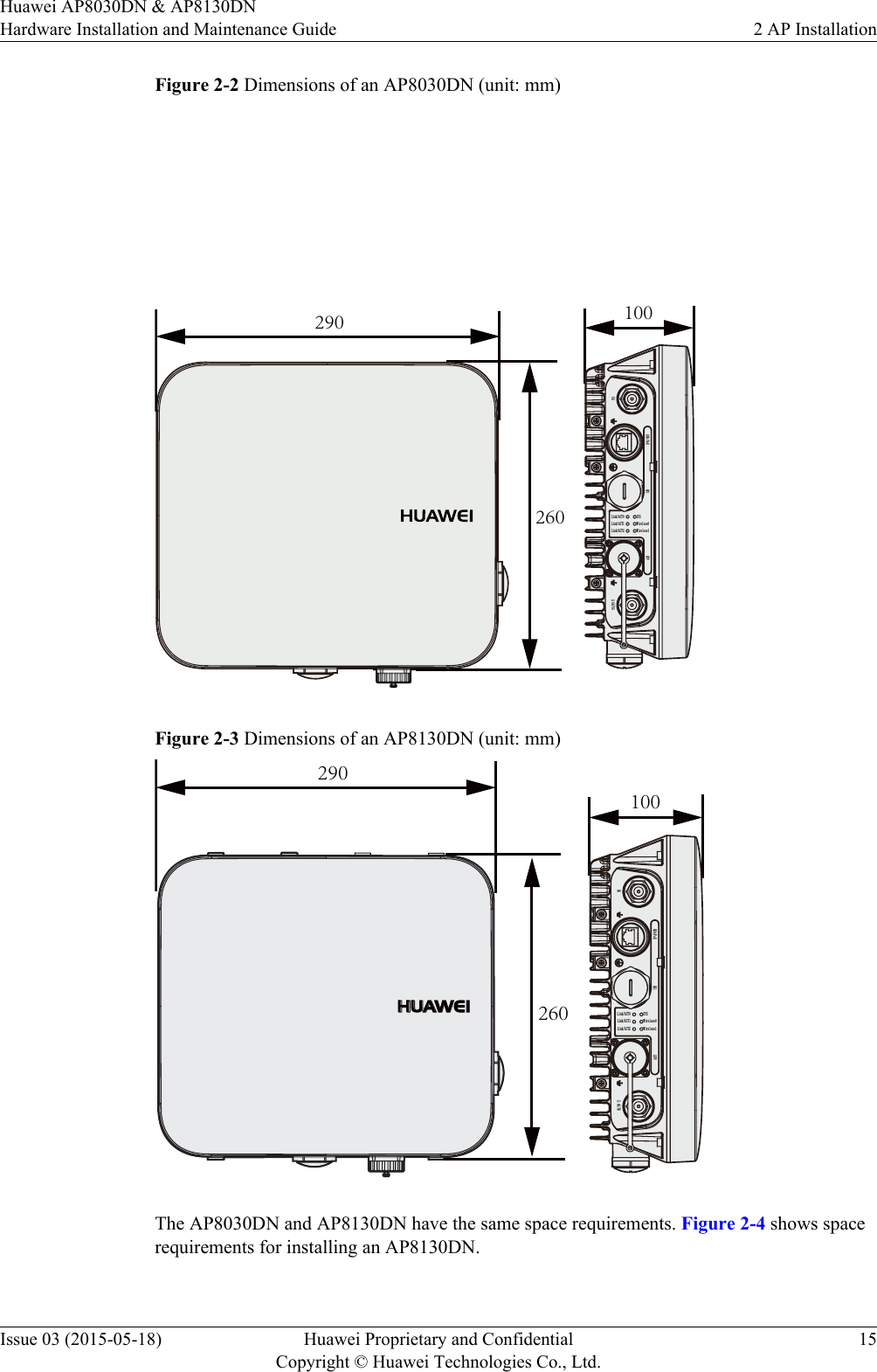
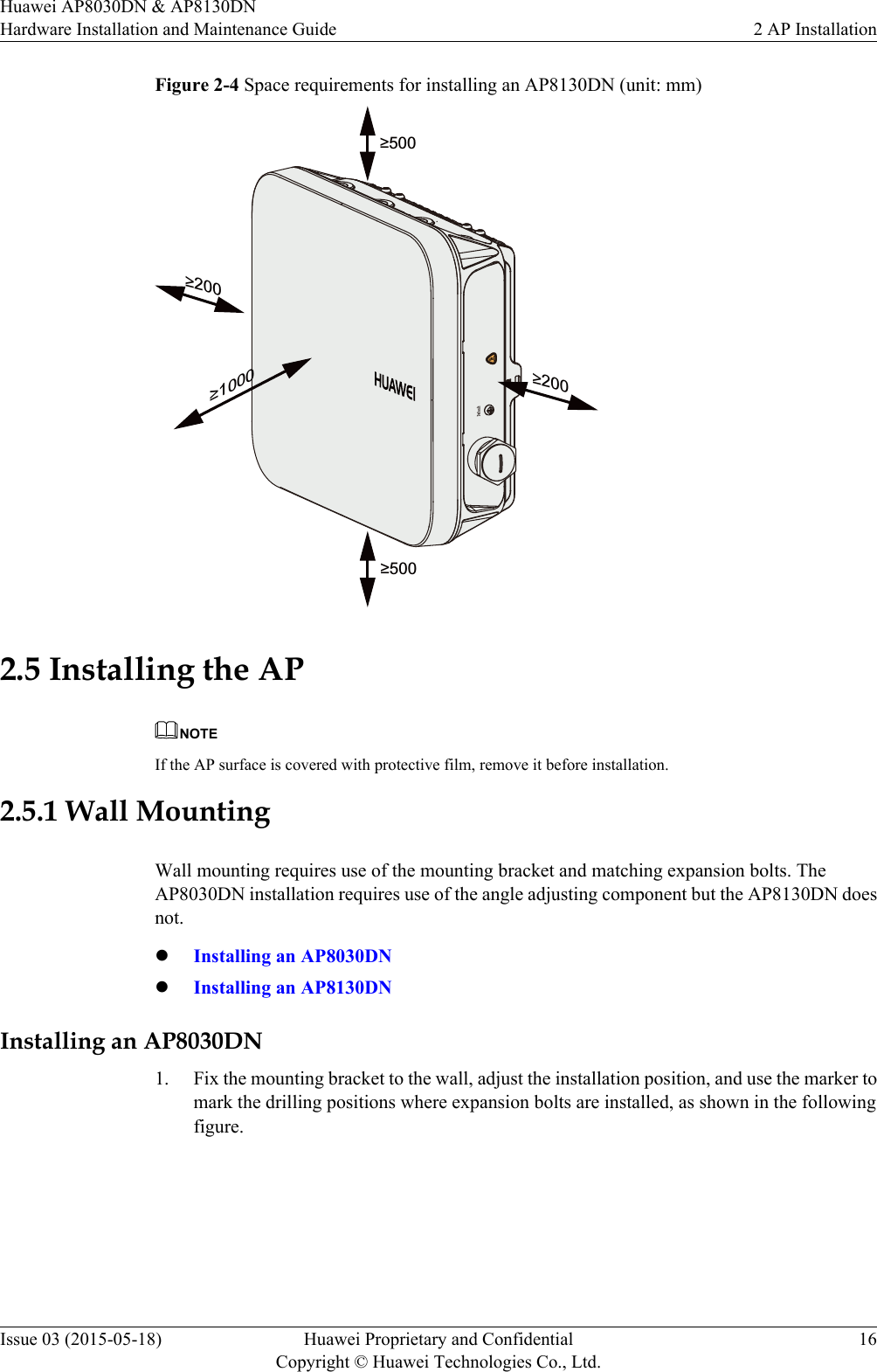
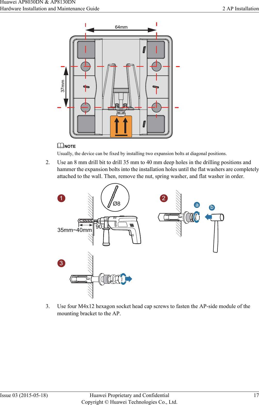
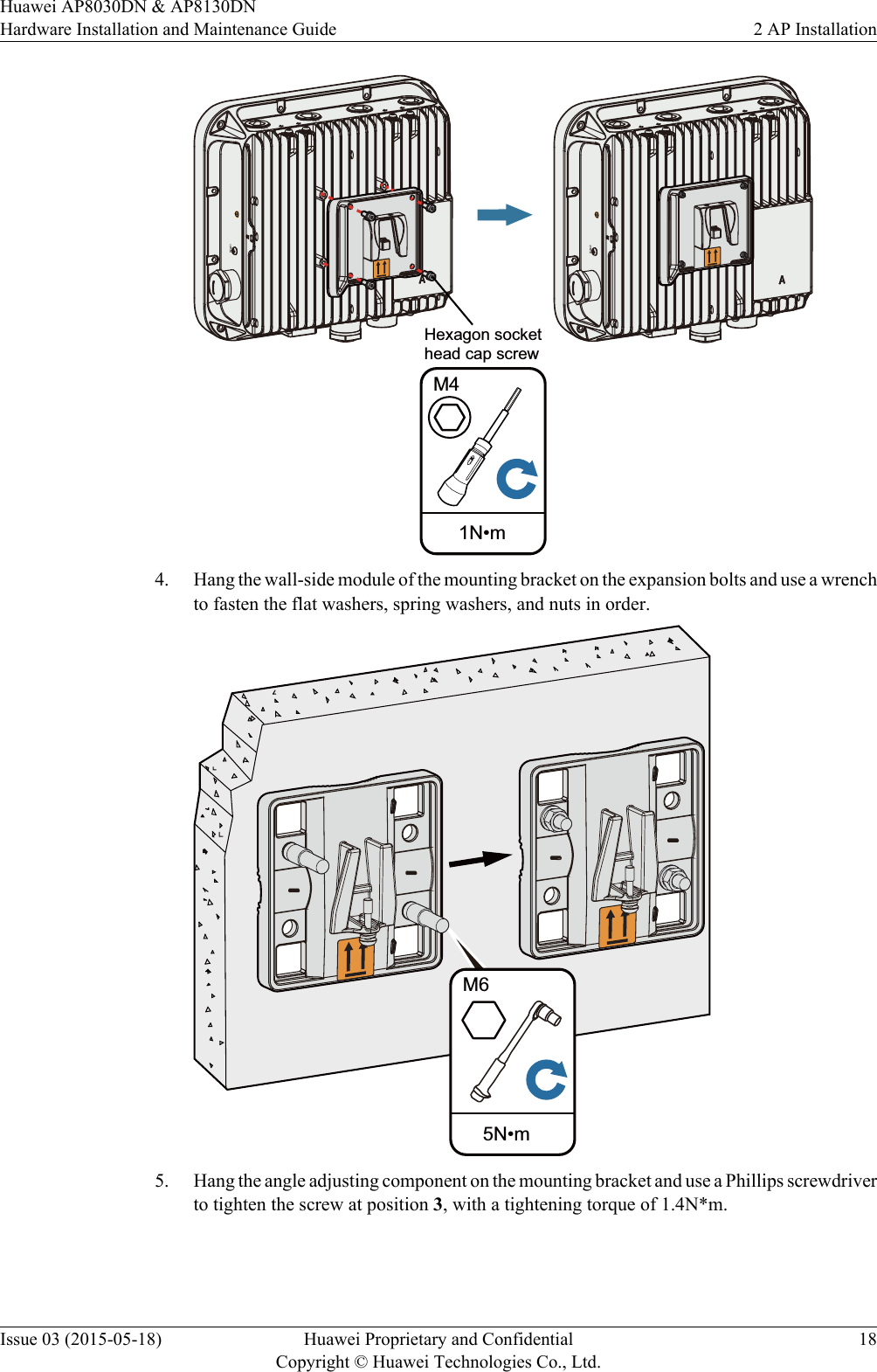
Huawei Technologies AP8130DN Outdoor Wireless LAN Access Point User Manual Hardware Installation and Maintenance Guide
Huawei Technologies Co.,Ltd Outdoor Wireless LAN Access Point Hardware Installation and Maintenance Guide
UserManual.wiki
>
Huawei Technologies
>
AP8130DN User Manual
>
Users Manual
Contents
1.
Users Manual
2.
User Manual
3.
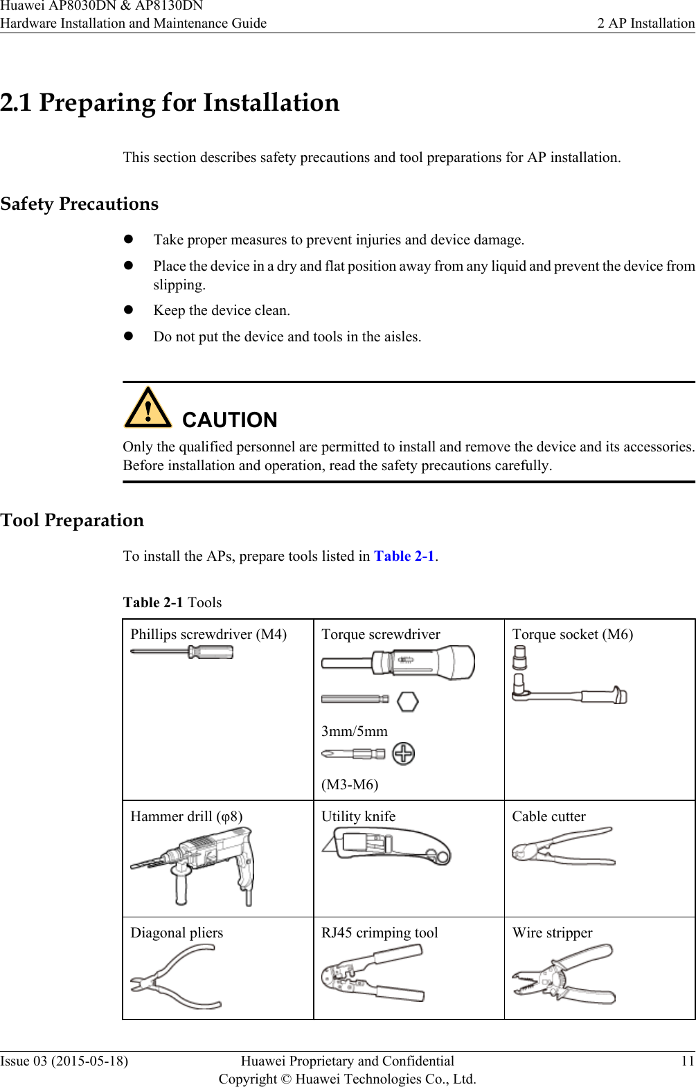
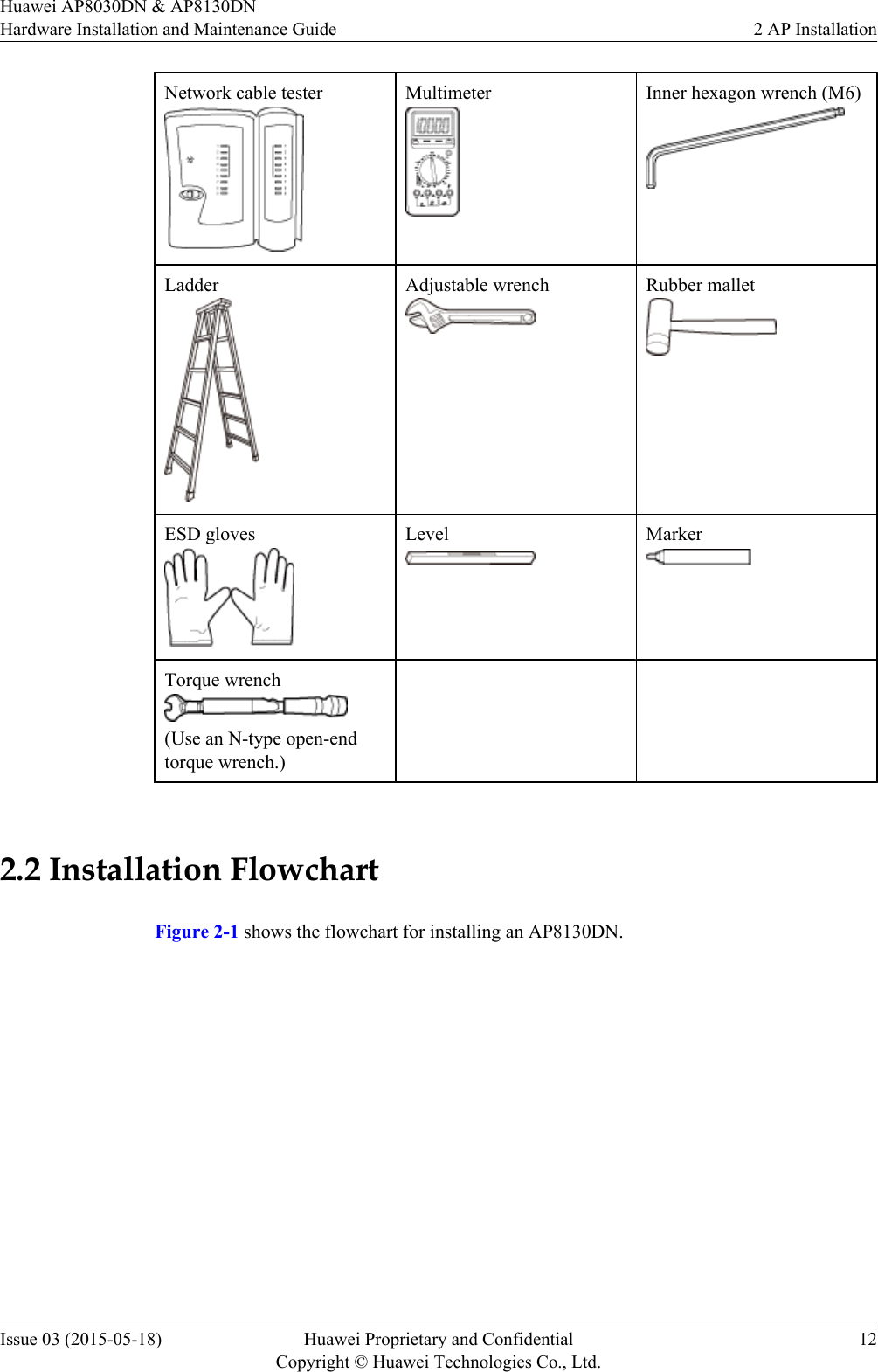
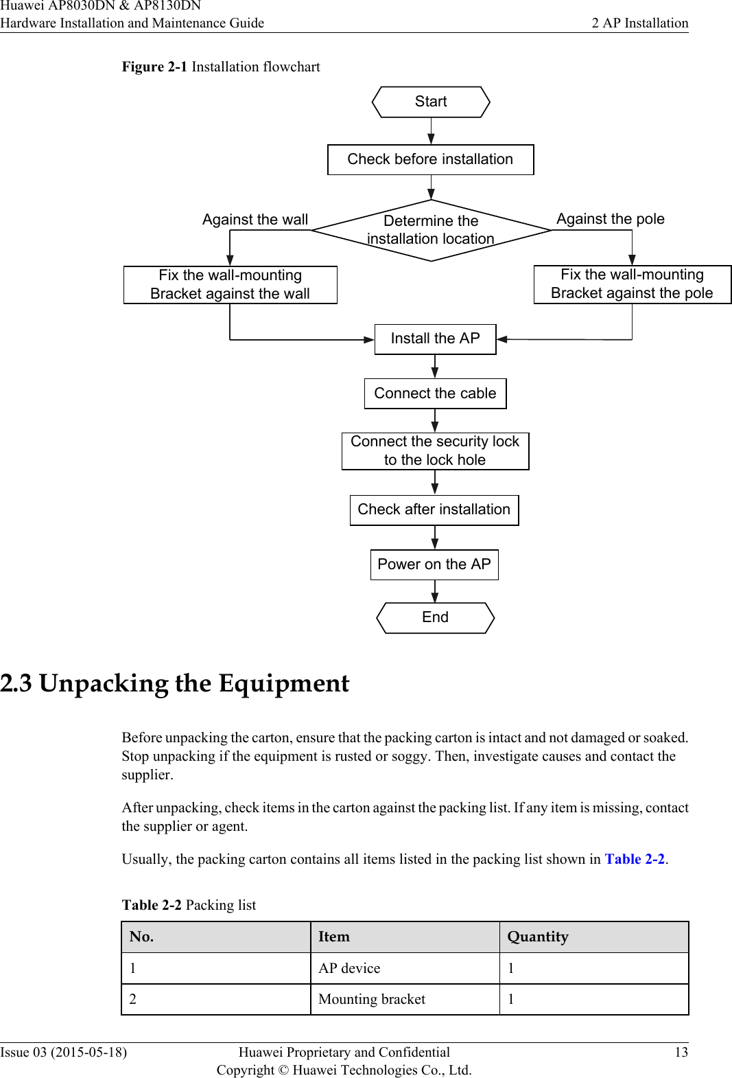
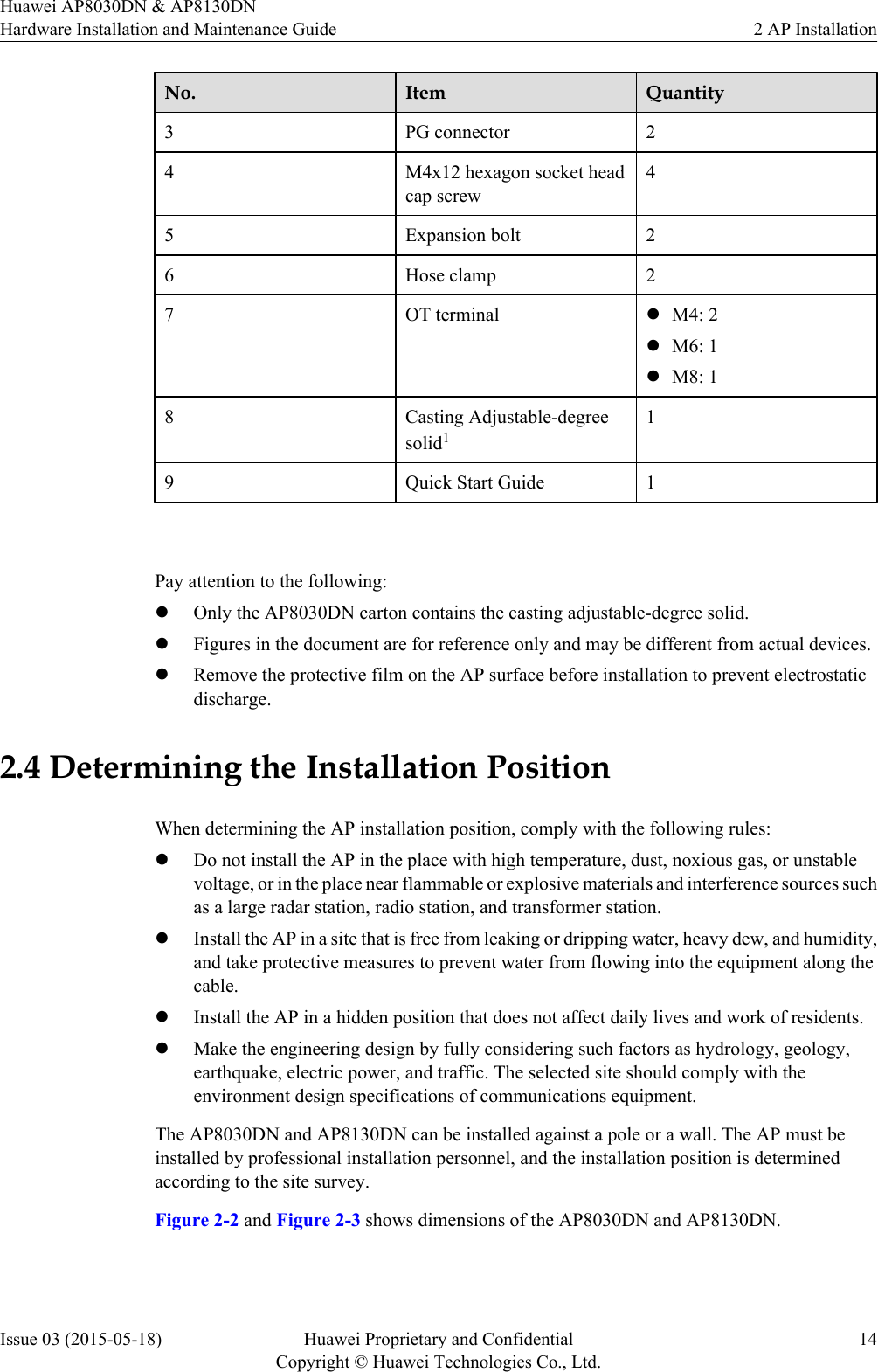
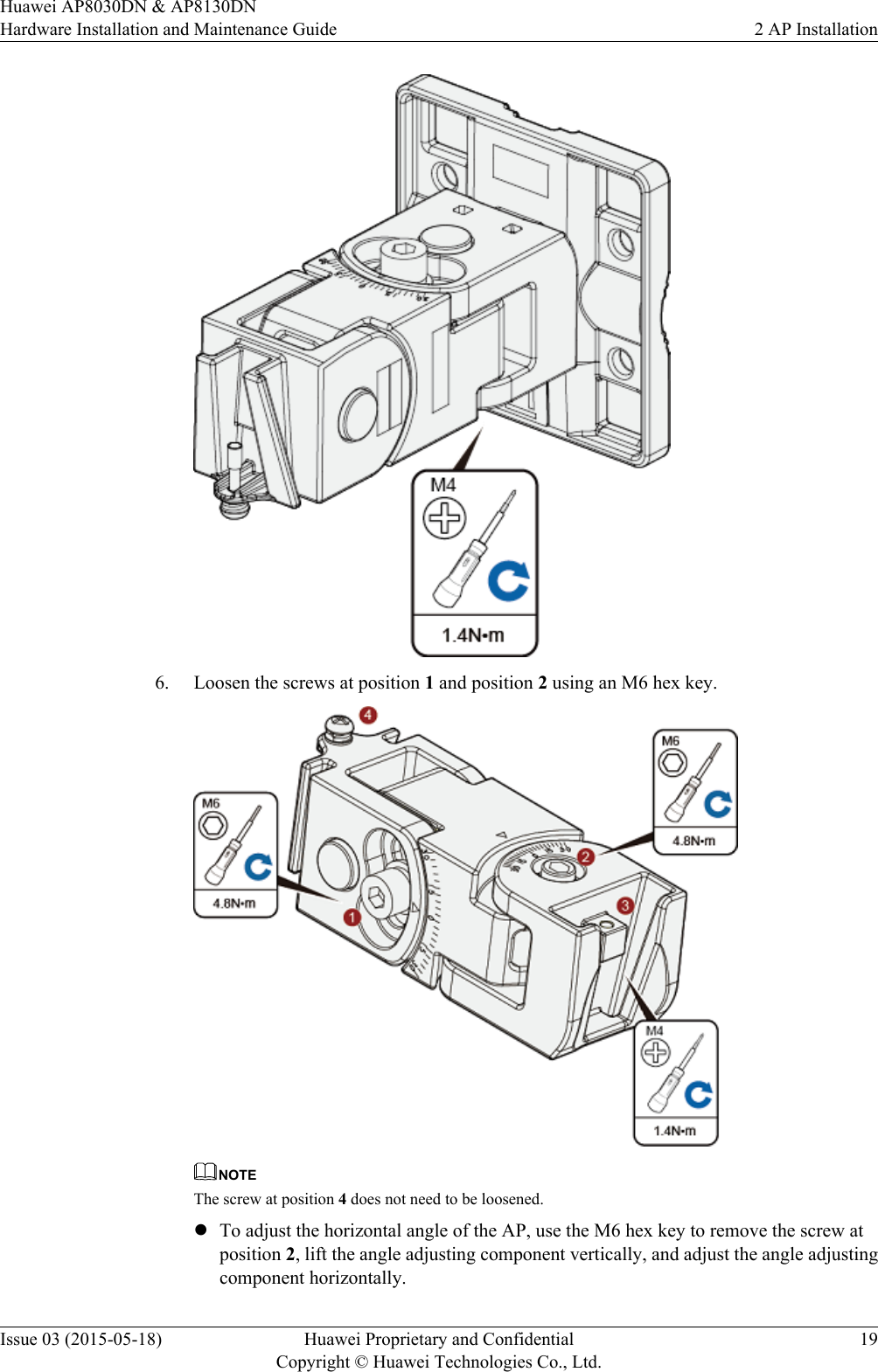
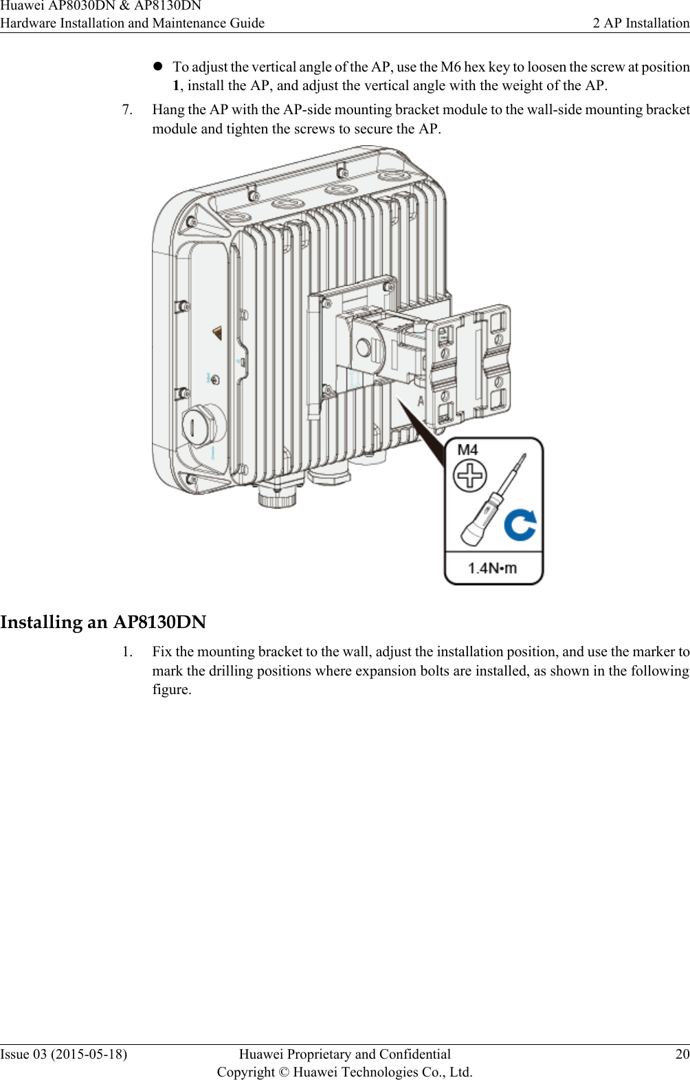
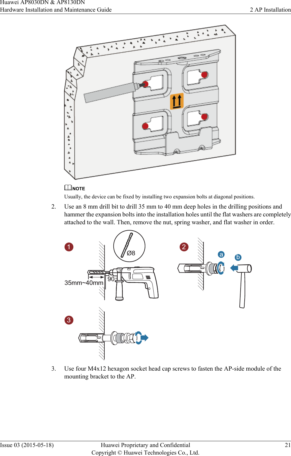
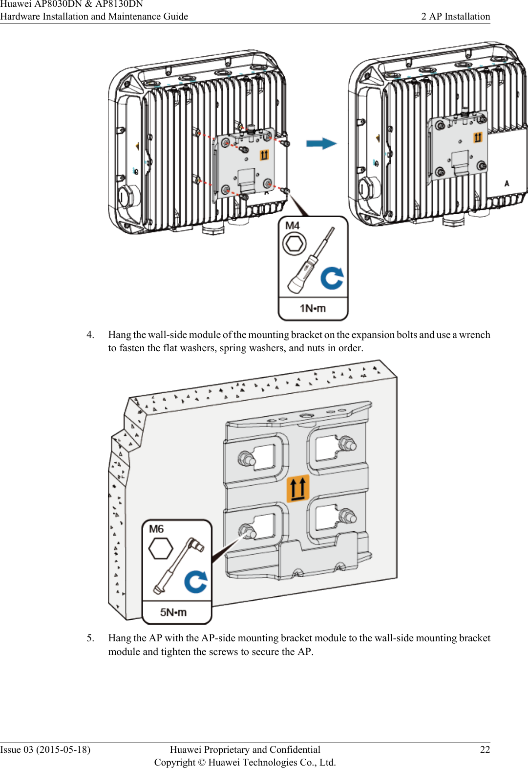
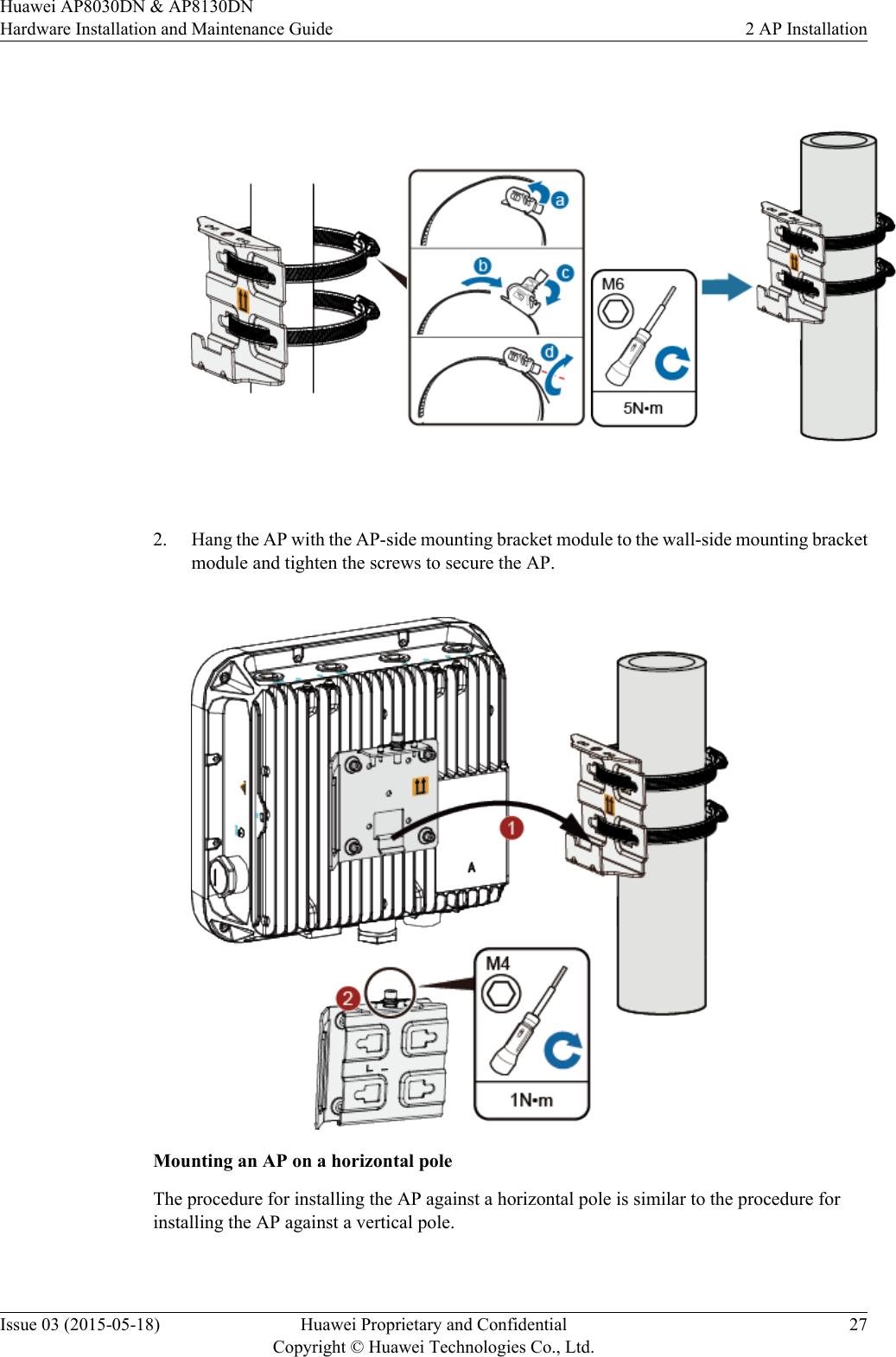
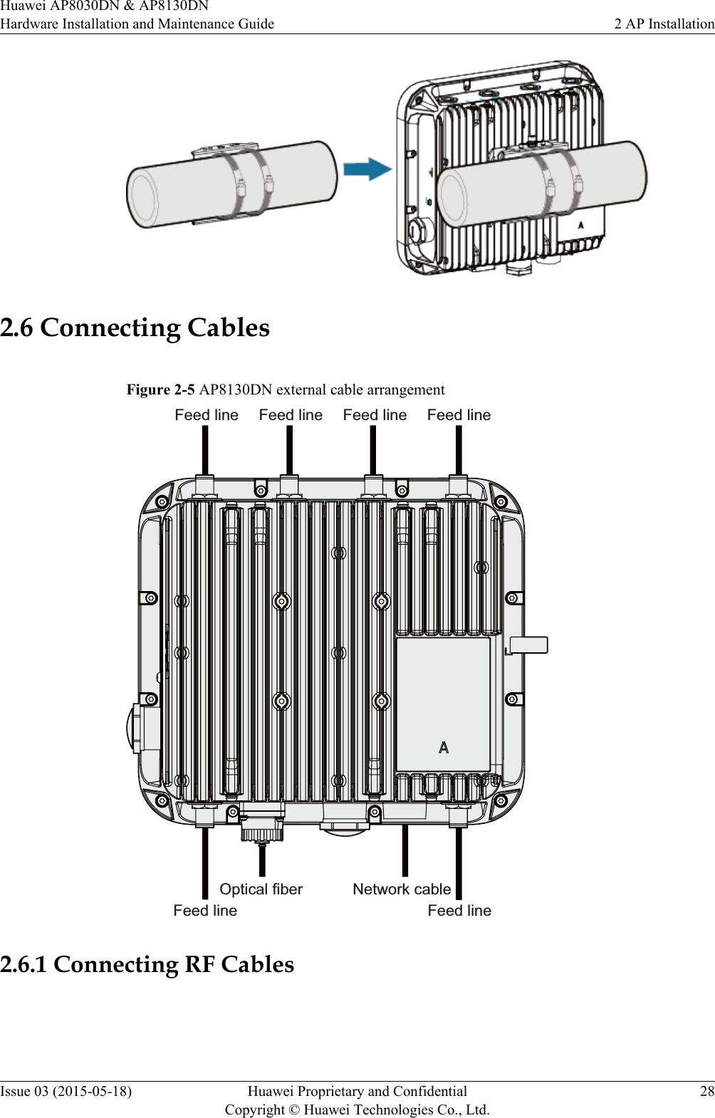
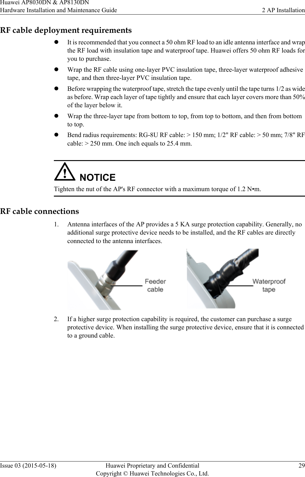
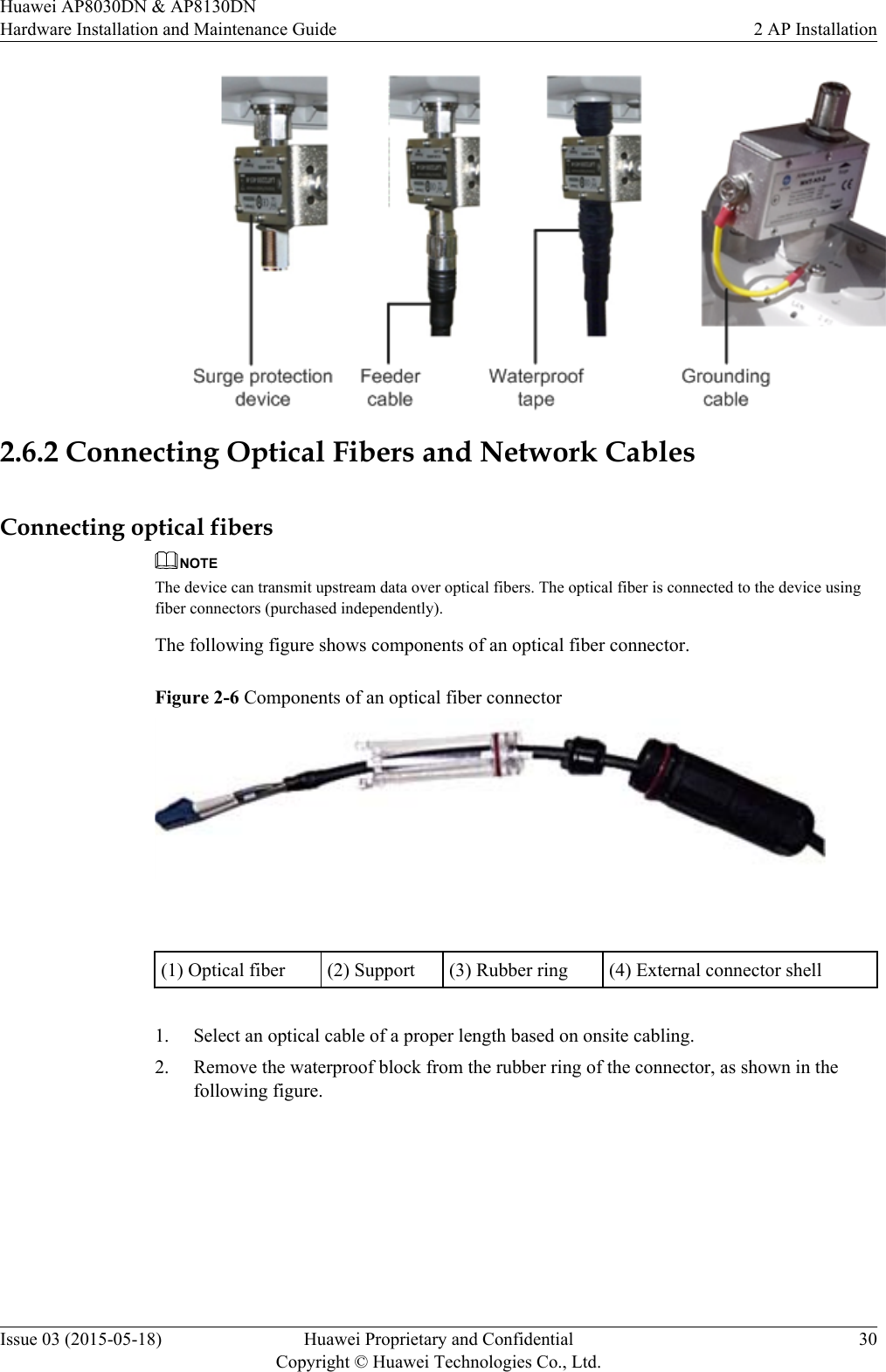
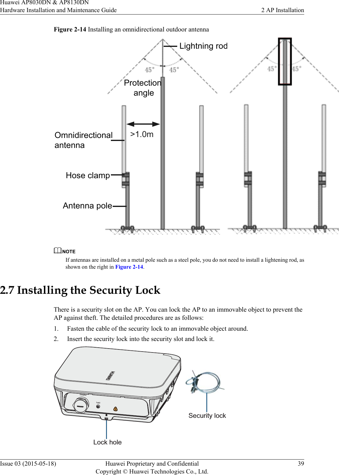
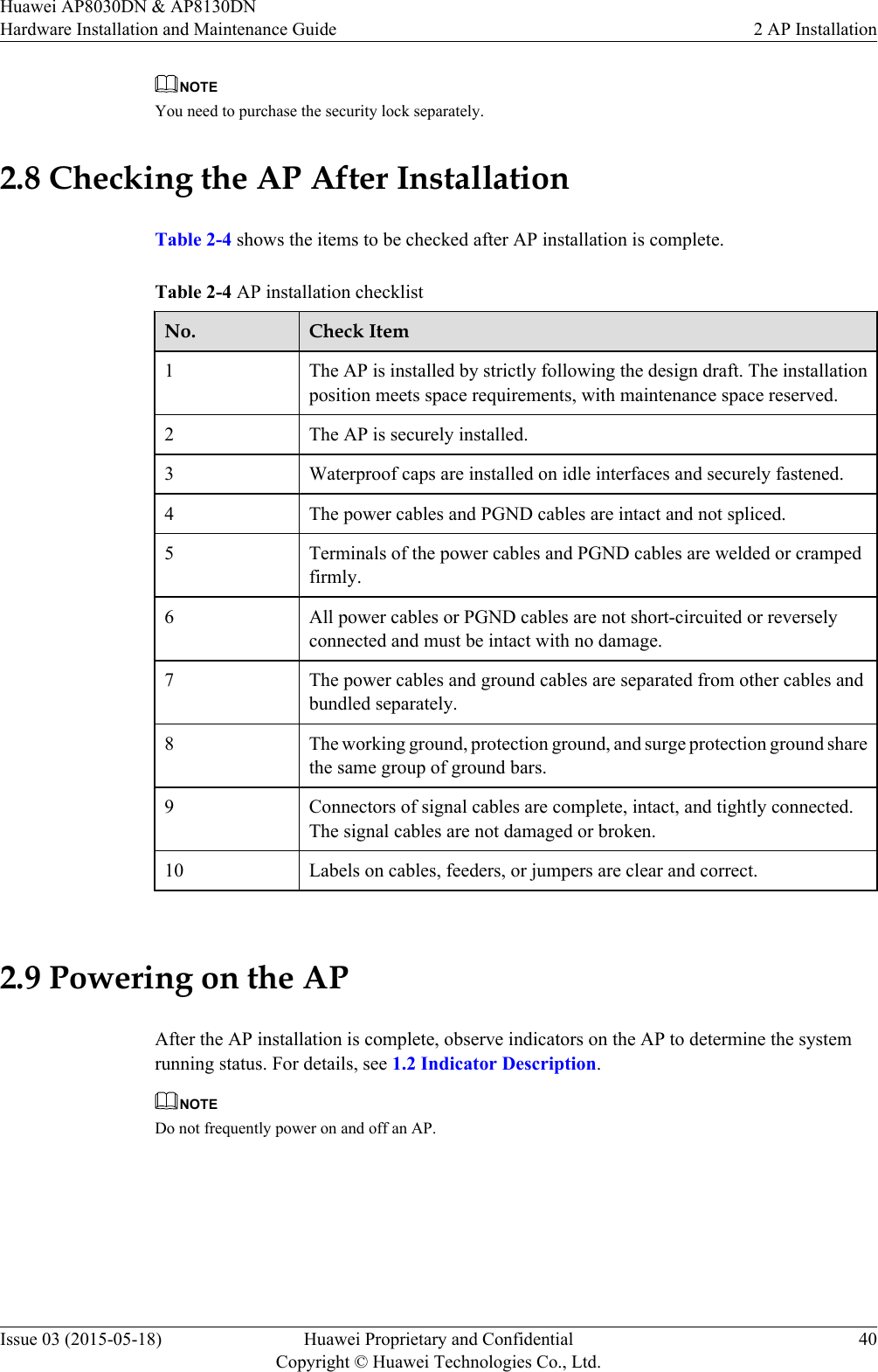
User ManualHardware Installation Guide
4.
User Manual_Hardware Installation Guide
Users Manual
Navigation menu
Upload a User Manual
Namespaces
Wiki Guide
HTML
PDF
Info
Views
User Manual
Discussion / Help
Navigation