Huawei Technologies AP8130DN Outdoor Wireless LAN Access Point User Manual Hardware Installation and Maintenance Guide
Huawei Technologies Co.,Ltd Outdoor Wireless LAN Access Point Hardware Installation and Maintenance Guide
Contents
Users Manual

Huawei AP8030DN & AP8130DN
Hardware Installation and
Maintenance Guide
Issue 03
Date 2015-05-18
HUAWEI TECHNOLOGIES CO., LTD.

Copyright © Huawei Technologies Co., Ltd. 2015. All rights reserved.
No part of this document may be reproduced or transmitted in any form or by any means without prior written
consent of Huawei Technologies Co., Ltd.
Trademarks and Permissions
and other Huawei trademarks are trademarks of Huawei Technologies Co., Ltd.
All other trademarks and trade names mentioned in this document are the property of their respective holders.
Notice
The purchased products, services and features are stipulated by the contract made between Huawei and the
customer. All or part of the products, services and features described in this document may not be within the
purchase scope or the usage scope. Unless otherwise specified in the contract, all statements, information,
and recommendations in this document are provided "AS IS" without warranties, guarantees or representations
of any kind, either express or implied.
The information in this document is subject to change without notice. Every effort has been made in the
preparation of this document to ensure accuracy of the contents, but all statements, information, and
recommendations in this document do not constitute a warranty of any kind, express or implied.
Huawei Technologies Co., Ltd.
Address: Huawei Industrial Base
Bantian, Longgang
Shenzhen 518129
People's Republic of China
Website: http://enterprise.huawei.com
Issue 03 (2015-05-18) Huawei Proprietary and Confidential
Copyright © Huawei Technologies Co., Ltd.
i
About This Document
Intended Audience
This document describes hardware features of the AP8030DN and AP8130DN and provides
basic installation methods.
This document is intended for:
lNetwork planning engineers
lHardware installation engineers
lCommissioning engineers
lOnsite maintenance engineers
lSystem maintenance engineers
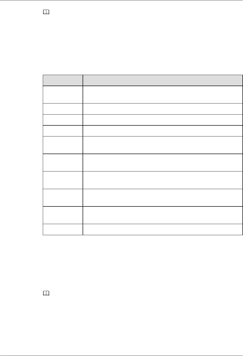
Symbol Conventions
The symbols that may be found in this document are defined as follows.
Symbol Description
Indicates an imminently hazardous situation
which, if not avoided, will result in death or
serious injury.
Indicates a potentially hazardous situation
which, if not avoided, could result in death or
serious injury.
Indicates a potentially hazardous situation
which, if not avoided, may result in minor or
moderate injury.
Indicates a potentially hazardous situation
which, if not avoided, could result in
equipment damage, data loss, performance
deterioration, or unanticipated results.
NOTICE is used to address practices not
related to personal injury.
Huawei AP8030DN & AP8130DN
Hardware Installation and Maintenance Guide About This Document
Issue 03 (2015-05-18) Huawei Proprietary and Confidential
Copyright © Huawei Technologies Co., Ltd.
ii

Symbol Description
NOTE
Calls attention to important information, best
practices and tips.
NOTE is used to address information not
related to personal injury, equipment damage,
and environment deterioration.
Change History
Changes between document issues are cumulative. The latest document issue contains all
changes made in previous issues.
Issue 03 (2015-05-18)
This version has the following updates:
The following information is modified:
lUpdated the mounting bracket.
lOptimized the cabling diagram.
lAdded the command to check AP running status in V200R006C00.
lAdded descriptions about PoE fault troubleshooting.
Issue 02 (2014-12-05)
This version has the following updates:
The following information is modified:
lInstallation of the angle adjusting component with AP8030DN is added.
The following information is added:
l1.4 Ordering Information.
Issue 01 (2014-08-20)
Initial commercial release
Huawei AP8030DN & AP8130DN
Hardware Installation and Maintenance Guide About This Document
Issue 03 (2015-05-18) Huawei Proprietary and Confidential
Copyright © Huawei Technologies Co., Ltd.
iii

Contents
About This Document.....................................................................................................................ii
1 AP8130DN & AP8030DN Overview..........................................................................................1
1.1 Device Structure.............................................................................................................................................................2
1.2 Indicator Description......................................................................................................................................................4
1.3 Basic Specifications........................................................................................................................................................7
1.4 Ordering Information......................................................................................................................................................8
2 AP Installation.............................................................................................................................10
2.1 Preparing for Installation..............................................................................................................................................11
2.2 Installation Flowchart...................................................................................................................................................12
2.3 Unpacking the Equipment............................................................................................................................................13
2.4 Determining the Installation Position...........................................................................................................................14
2.5 Installing the AP...........................................................................................................................................................16
2.5.1 Wall Mounting...........................................................................................................................................................16
2.5.2 Pole Mounting...........................................................................................................................................................23
2.6 Connecting Cables........................................................................................................................................................28
2.6.1 Connecting RF Cables...............................................................................................................................................28
2.6.2 Connecting Optical Fibers and Network Cables.......................................................................................................30
2.6.3 Connecting Ground Cables........................................................................................................................................33
2.6.4 Installing Outdoor Antennas......................................................................................................................................36
2.7 Installing the Security Lock..........................................................................................................................................39
2.8 Checking the AP After Installation..............................................................................................................................40
2.9 Powering on the AP......................................................................................................................................................40
3 Logging In to the AP...................................................................................................................41
3.1 Logging In to the AP Through the Console Port..........................................................................................................42
3.2 Logging In to the AP Using STelnet............................................................................................................................42
3.3 Logging In to the AP Using Telnet..............................................................................................................................43
3.4 Logging In to the AP Using a Web Client....................................................................................................................44
4 Hardware Failures.......................................................................................................................46
4.1 An device Fails to Be Powered On...............................................................................................................................47
4.2 An Optical Interface Cannot Turn Up..........................................................................................................................47
5 Appendix.......................................................................................................................................49
Huawei AP8030DN & AP8130DN
Hardware Installation and Maintenance Guide Contents
Issue 03 (2015-05-18) Huawei Proprietary and Confidential
Copyright © Huawei Technologies Co., Ltd.
iv

5.1 On-site Cable Assembly and Installation.....................................................................................................................50
5.1.1 Cable Assembly Precautions.....................................................................................................................................50
5.1.2 Assembling Power Cables.........................................................................................................................................51
5.1.3 Assembling Ethernet Cables......................................................................................................................................59
5.1.4 Installing Cable Accessories......................................................................................................................................73
5.1.5 Replacing the Mold of the Crimping Pliers...............................................................................................................89
5.2 Environmental Requirements for Device Operation....................................................................................................92
5.2.1 Environmental Requirements for an Equipment Room............................................................................................92
5.2.2 Requirements for Power Supply..............................................................................................................................100
5.3 Equipment Grounding Specifications.........................................................................................................................103
5.3.1 General Grounding Specifications...........................................................................................................................103
5.3.2 Grounding Specifications for an Equipment Room................................................................................................103
5.3.3 Grounding Specifications for Devices.....................................................................................................................103
5.3.4 Grounding Specifications for Communications Power Supply...............................................................................104
5.3.5 Grounding Specifications for Signal Cables...........................................................................................................105
5.3.6 Specifications for Laying Out Grounding Cables...................................................................................................105
5.4 Engineering Labels for Cables...................................................................................................................................106
5.4.1 Introduction to Labels..............................................................................................................................................106
5.4.2 Engineering Labels for Optical Fibers.....................................................................................................................114
5.4.3 Engineering Labels for Network Cables.................................................................................................................117
5.4.4 Engineering Labels for User Cables........................................................................................................................118
5.4.5 Engineering Labels for Power Cables.....................................................................................................................119
5.5 Guide to Using Optical Modules................................................................................................................................122
5.6 Fault Tag.....................................................................................................................................................................125
Huawei AP8030DN & AP8130DN
Hardware Installation and Maintenance Guide Contents
Issue 03 (2015-05-18) Huawei Proprietary and Confidential
Copyright © Huawei Technologies Co., Ltd.
v

1 AP8130DN & AP8030DN Overview
About This Chapter
Huawei AP8030DN and AP8130DN is the latest-generation 802.11ac outdoor access point (AP)
that supports 3x3 MIMO. The AP is physically hardened and features enhanced outdoor
coverage performance. It supports 2.4 GHz and 5 GHz frequency bands, complies with IEEE
802.11a/b/g/n/ac, and can work as wireless bridges. The AP can provide services simultaneously
on the 2.4 GHz and 5 GHz frequency bands to support more access users. It provides
comprehensive service support capabilities and features high reliability, high security, simple
network deployment, automatic AC discovery and configuration, and real-time management
and maintenance, which meets requirements of outdoor deployment.
Huawei AP8030DNs and AP8130DNs comply with IP67 dustproof and waterproof protection
standards, applicable to coverage scenarios (for example, squares, pedestrian streets, and
amusement parks) and bridging scenarios (for example, wireless harbors, data backhaul, video
surveillance, and train-to-ground backhaul).
1.1 Device Structure
1.2 Indicator Description
1.3 Basic Specifications
1.4 Ordering Information
To place an order, contact the Huawei local office.
Huawei AP8030DN & AP8130DN
Hardware Installation and Maintenance Guide 1 AP8130DN & AP8030DN Overview
Issue 03 (2015-05-18) Huawei Proprietary and Confidential
Copyright © Huawei Technologies Co., Ltd.
1
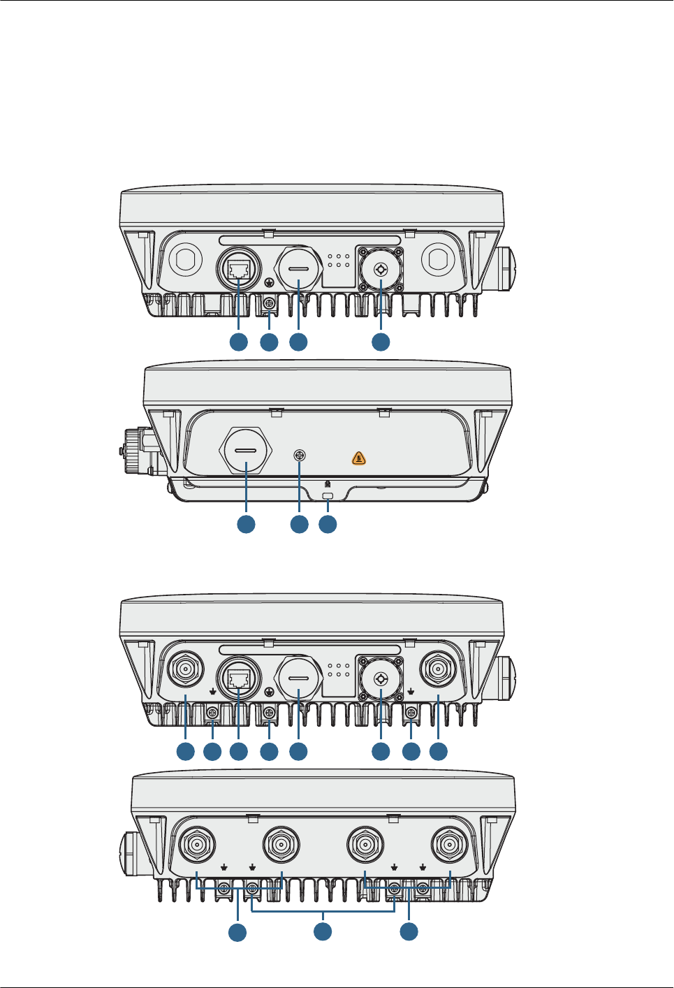
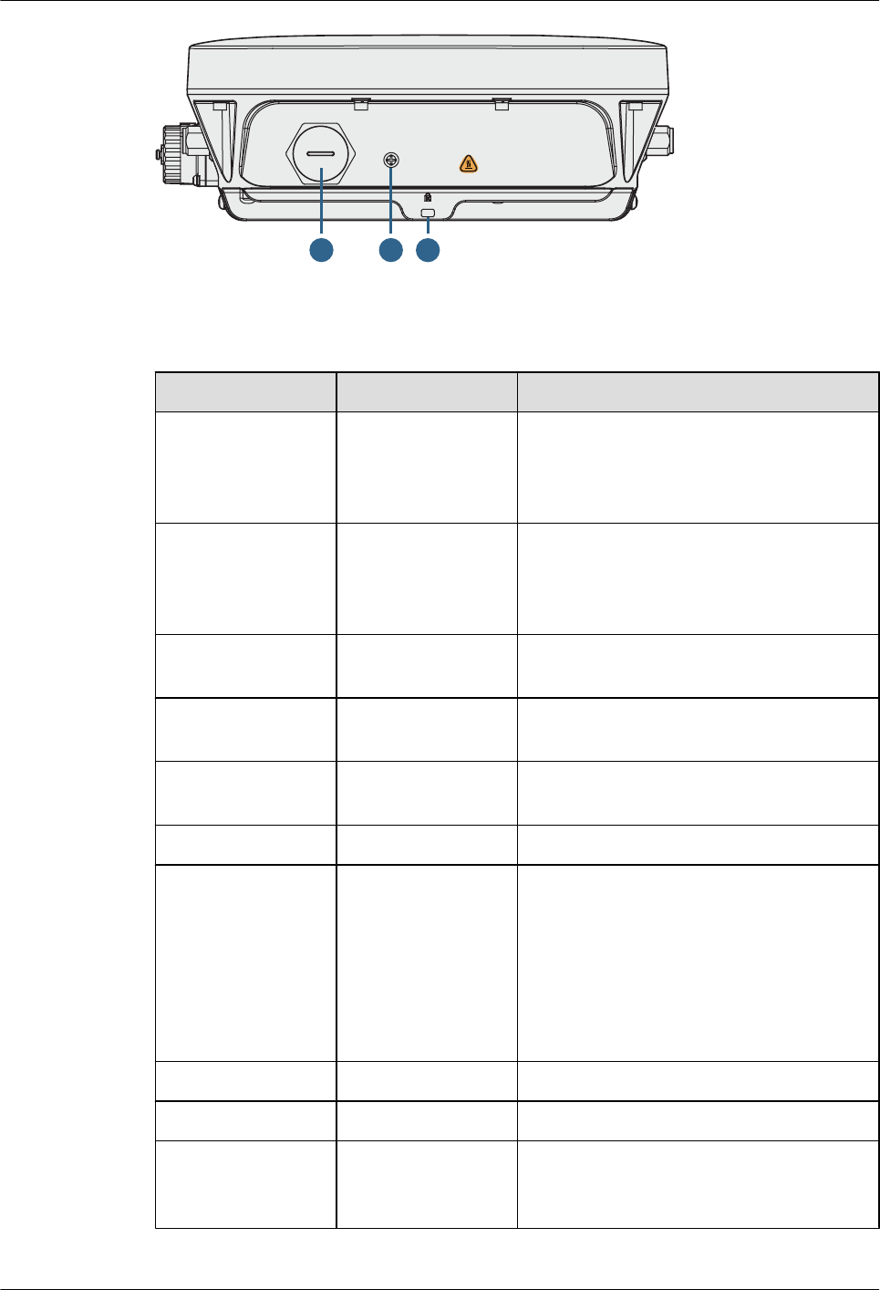
1.1 Device Structure
Figure 1-1 and Figure 1-2 shows the appearance of the AP8030DN and AP8130DN.
Figure 1-1 AP8030DN appearance
GE0/PoE GE1 SFP
SYS
Link/ACT1
Wireless1
Link/ACT0
Wireless0
Link/ACT2
1 3
2
9
Console
Default
678
Figure 1-2 AP8130DN appearance
5G
GE0/PoE
GE1
SFP
SYS
2.4G/5G
Link/ACT1
Wireless1
Link/ACT0
Wireless0
Link/ACT2
1 3
2
4 5
10 9 10
2.4G/5G
2.4G/5G 5G 5G
54
10
Huawei AP8030DN & AP8130DN
Hardware Installation and Maintenance Guide 1 AP8130DN & AP8030DN Overview
Issue 03 (2015-05-18) Huawei Proprietary and Confidential
Copyright © Huawei Technologies Co., Ltd.
2
Console
Default
678
Table 1-1 describes interfaces on the AP8030DN and AP8130DN.
Table 1-1 Descriptions of interfaces
No. Name Description
1GE0/PoE 10/100/1000M bit/s interface: connects to the
wired Ethernet. The interface can connect to
a PoE power supply to provide power for the
AP.
2 GE1 10/100/1000M bit/s interface: connects to the
wired Ethernet. The interface can't connect to
a PoE power supply to provide power for the
AP.
3 SFP Connects an optical fiber to the AP. An
optical module must be installed first.
4 5G antenna interface Connects a 2.4GHz antenna to the AP to send
and receive service signals.
5 2.4G or 5G antenna
interface
Connects a 2.4GHz or 5GHz antenna to the
AP to send and receive service signals.
6 Console Console: Console interface
7 Default Reset button: restores factory settings and
restarts the AP if you hold down the Reset
button for more than 3 seconds.
NOTE
The Reset button is protected by a waterproof
screw. Before pressing the Reset button, remove
the waterproof screw. Keep the screw properly and
install it again after pressing the Reset button.
8 Security slot Connects to a security lock.
9 Device ground screw Connects a ground cable to the AP.
10 Ground screw for the
surge protective
device
Connects the AP to the ground point of an
external surge protective device.
Huawei AP8030DN & AP8130DN
Hardware Installation and Maintenance Guide 1 AP8130DN & AP8030DN Overview
Issue 03 (2015-05-18) Huawei Proprietary and Confidential
Copyright © Huawei Technologies Co., Ltd.
3
NOTE
The AP8130DN offers two internal DB9 ports, which have similar functions as external GE ports. In device
usage, you are advised to connect the device through the GE ports but not the DB9 ports.
CAUTION
There is a scald warning label attached on the device, warning you not to touch the device after
the device has been operating for a long time.
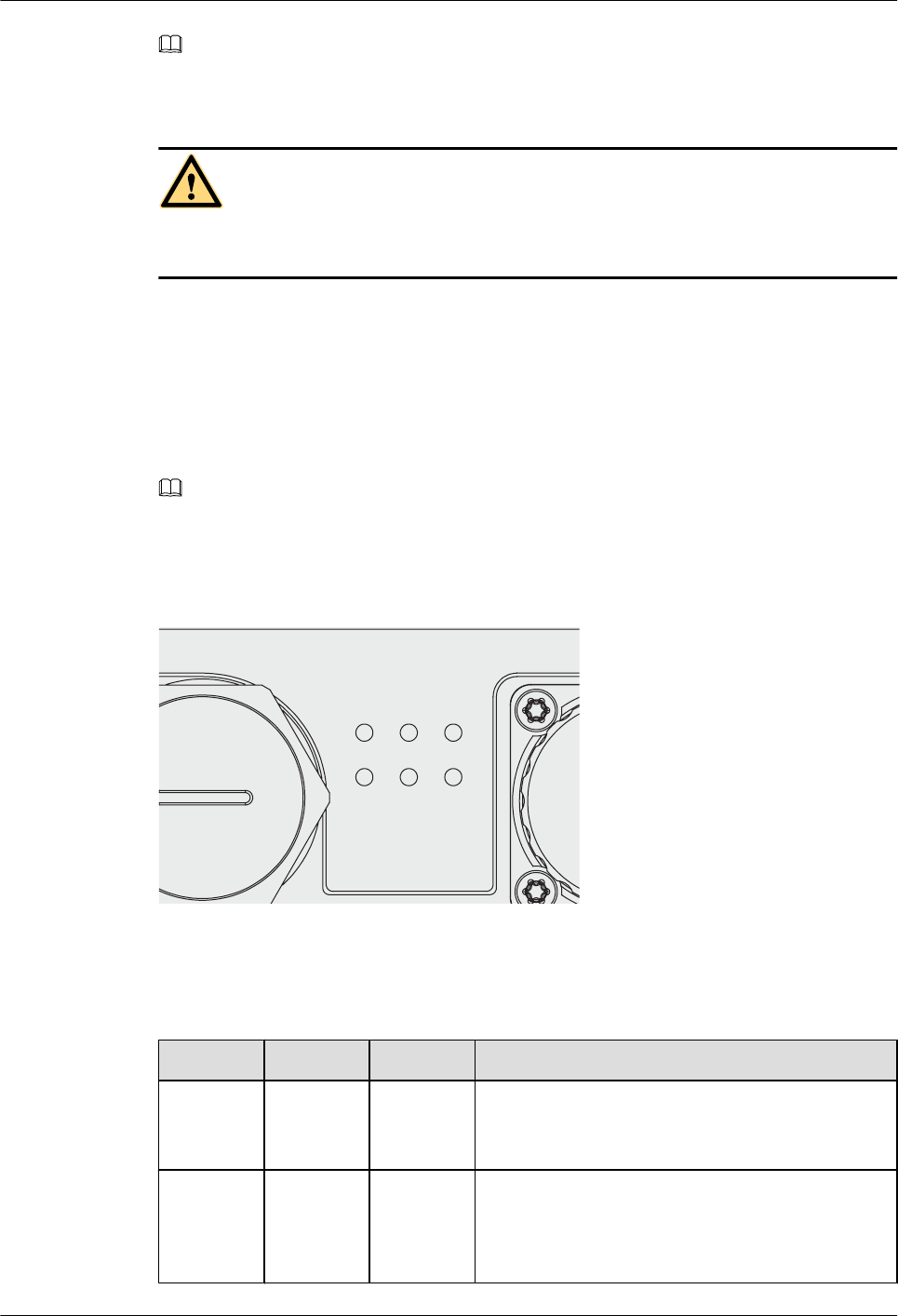
1.2 Indicator Description
The AP8030DN and AP8130DN provides multiple indicators: SYS indicator, Link/ACT
indicator, and Wireless indicator. The following tables describe indicators on the AP8030DN
and AP8130DN.
NOTE
lIndicator colors may vary slightly at different temperature.
lAfter a Fit AP is powered on, you can run the led off command on the AC to turn off all AP indicators.
To restore the indicators to normal working status, run the led on command. Indicators on a Fat AP
cannot be turned off using the led off command.
GE1
SYS
Link/A CT1
Wire less1
Link/A CT0
Wire less0
Link/A CT2
SYS indicator
Table 1-2 Descriptions about the SYS indicator
Type Color Status Description
Default
status after
power-on
Green Steady on The AP is just powered on and the software is not
started yet.
Software
startup
status
Green Steady on
after
blinking
once
After the system is reset and starts uploading the
software, the indicator blinks green once. Until the
software is uploaded and started, the indicator
remains steady green.
Huawei AP8030DN & AP8130DN
Hardware Installation and Maintenance Guide 1 AP8130DN & AP8030DN Overview
Issue 03 (2015-05-18) Huawei Proprietary and Confidential
Copyright © Huawei Technologies Co., Ltd.
4

Type Color Status Description
Running
status
Green Blinking
once every
2s (0.5 Hz)
lThe system is running properly, the Ethernet
connection is normal, and STAs are associated
with the AP.
lThe system enters the Uboot CLI.
Blinking
once every
5s (0.2 Hz)
The system is running properly, the Ethernet
connection is normal, and no STA is associated with
the AP. The system is in low power consumption
state.
Alarm Green Blinking
once every
0.25s (4
Hz)
lThe software is being upgraded.
lAfter the software is uploaded and started, the AP
working in Fit AP mode requests to go online on
the AC and maintains this state until it goes
online successfully on the AC (before the
CAPWAP link is established).
lThe AP working in Fit AP mode fails to go online
on the AC (the CAPWAP link disconnects).
Fault Red Steady on A fault that affects services has occurred, such as a
DRAM detection failure or system software loading
failure. The fault cannot be automatically rectified
and must be rectified manually.
Link/ACT indicators
Link/ACT indicators consist of Link/ACT0, Link/ACT1, and Link/ACT2, showing link status
of interfaces GE0/PoE, GE1, SFP respectively.
Table 1-3 Descriptions about the Link/ACT indicators
Type Color Status Description
LINK Green Steady on The system is running properly, the Ethernet
connection is normal, and no data is being
transmitted.
ACT Green Blinking The system is running properly, the Ethernet
connection is normal, and the AP is transmitting
data. The indicator blinks more quickly when more
data is being transmitted.
Wireless indicators
Wireless indicators consist of Wireless0 and Wireless1, showing wireless link status of the 5
GHz and 2.4/5 GHz radio interfaces respectively.
Huawei AP8030DN & AP8130DN
Hardware Installation and Maintenance Guide 1 AP8130DN & AP8030DN Overview
Issue 03 (2015-05-18) Huawei Proprietary and Confidential
Copyright © Huawei Technologies Co., Ltd.
5
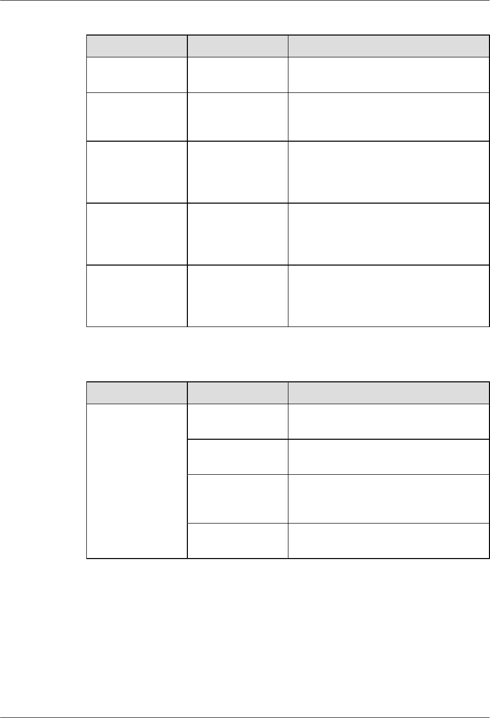
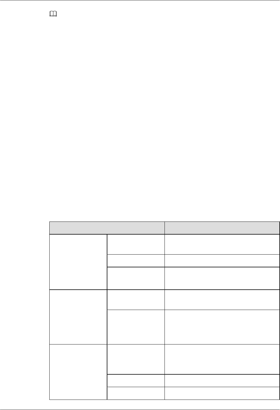
Table 1-4 Traffic volume indicator
Color Status Description
Yellow/green Off Radios are disabled, and no STA is connected
to the AP.
Yellow/green Steady on The AP has STAs connected to the 2.4 GHz
radio or 5 GHz radio, but no data is being
transmitted.
Green Blinking The AP has STAs connected to the 2.4 GHz
radio and is transmitting data. The indicator
blinks more quickly when more data is being
transmitted.
Yellow Blinking The AP has STAs connected to the 5 GHz
radio and is transmitting data. The indicator
blinks more quickly when more data is being
transmitted.
Yellow/green Blinking
alternatively
The AP has STAs connected to both the 2.4
GHz radio and 5 GHz radio. The indicator
blinks more quickly when more data is being
transmitted.
Table 1-5 Wireless bridge indicator
Color Status Description
Yellow/green Off The AP is not transmitting or receiving data
or the signal strength is extremely low.
Blinking once every
2s (0.5 Hz)
The AP is transmitting or receiving data
normally, and the signal strength is low.
Blinking green once
every 0.25 seconds (4
Hz)
The AP is transmitting or receiving data
normally, and the signal strength is medium.
Steady on The AP is transmitting or receiving data
normally, and the signal strength is high.
Huawei AP8030DN & AP8130DN
Hardware Installation and Maintenance Guide 1 AP8130DN & AP8030DN Overview
Issue 03 (2015-05-18) Huawei Proprietary and Confidential
Copyright © Huawei Technologies Co., Ltd.
6
NOTE
When the WDS/mesh function is enabled on an AP, the blinking frequency of its Wireless LED indicates
the receive signal strength on the WDS/mesh connection by default. After you connect an AP to a WDS/
mesh network, you can run the wifi-light { signal-strength | traffic } command on the AC to make the
Wireless LED blinking frequency indicate receive signal strength or service traffic rate.
lwifi-light signal-strength:
lIf the mesh function is enabled on the AP, the blinking frequency of the Wireless LED reflects
the weakest signal strength of all neighboring APs.
lIf WDS is enabled on an AP, the blinking frequency of the Wireless LED reflects the strength
of signals received from a WDS AP.
lIf the AP works in leaf mode, the blinking frequency of the Wireless LED reflects the strength
of signals received from a middle AP.
lIf the AP works in middle mode, the blinking frequency of the Wireless LED reflects the
strength of signals received from a root AP.
lIf the AP works in root mode, the blinking frequency of the Wireless LED reflects the weakest
signal strength of middle APs.
lwifi-light traffic: allows the Wireless LED to reflect the service traffic volume on the radio.
The Fat AP does not support WDS/Mesh functions; therefore, the Wireless indicator of the Fat AP does
not indicate the signal strength.
1.3 Basic Specifications
Table 1-6 and Table 1-7 provides basic specifications of the AP8030DN and AP8130DN.
Table 1-6 Basic Specifications of the AP8030DN
Item Description
Technical
specifications
Dimensions (H x W x
D)
100 mm x 290 mm x 260 mm
Weight 3.6 kg
System memory l256 MB DDR3
l64 MB Flash
Power specifications Power input PoE power supply: -48 V DC (in compliance
with IEEE 802.3at)
Maximum power
consumption
20.1 W
NOTE
The actual maximum power consumption depends
on local laws and regulations.
Environment
specifications
Operating
temperature
-60 m to +1800 m: -40°C to +60°C
1800 m to 5000 m: Temperature decreases by
1°C every time the altitude increases 220 m.
Storage temperature -40°C to +70°C
Operating humidity 0% to 100% (non-condensing)
Huawei AP8030DN & AP8130DN
Hardware Installation and Maintenance Guide 1 AP8130DN & AP8030DN Overview
Issue 03 (2015-05-18) Huawei Proprietary and Confidential
Copyright © Huawei Technologies Co., Ltd.
7
Item Description
IP rating IP67
Atmospheric
pressure
53 kPa to 106 kPa
Table 1-7 Basic Specifications of the AP8130DN
Item Description
Technical
specifications
Dimensions (H x W x
D)
100 mm x 290 mm x 260 mm
Weight 4.0 kg
System memory l256 MB DDR3
l64 MB Flash
Power specifications Power input PoE power supply: -48 V DC (in compliance
with IEEE 802.3at)
Maximum power
consumption
22.4 W
NOTE
The actual maximum power consumption depends
on local laws and regulations.
Environment
specifications
Operating
temperature
-60 m to +1800 m: -40°C to +60°C
1800 m to 5000 m: Temperature decreases by
1°C every time the altitude increases 220 m.
Storage temperature -40°C to +70°C
Operating humidity 0% to 100% (non-condensing)
IP rating IP67
Atmospheric
pressure
53 kPa to 106 kPa
1.4 Ordering Information
To place an order, contact the Huawei local office.
Part Number Description
02350ALD Assembling
Components,AP8030DN,AP8030DN,AP8030DN
Mainframe(11ac,General AP Outdoor,3x3 Double
Frequency,Built-in Antenna)
Huawei AP8030DN & AP8130DN
Hardware Installation and Maintenance Guide 1 AP8130DN & AP8030DN Overview
Issue 03 (2015-05-18) Huawei Proprietary and Confidential
Copyright © Huawei Technologies Co., Ltd.
8

Part Number Description
02359462 Assembling
Components,AP8130DN,AP8130DN,AP8130DN
Mainframe(11ac,General AP Outdoor,3x3 Double
Frequency,External Antenna)
Huawei AP8030DN & AP8130DN
Hardware Installation and Maintenance Guide 1 AP8130DN & AP8030DN Overview
Issue 03 (2015-05-18) Huawei Proprietary and Confidential
Copyright © Huawei Technologies Co., Ltd.
9

2 AP Installation
About This Chapter
2.1 Preparing for Installation
2.2 Installation Flowchart
2.3 Unpacking the Equipment
2.4 Determining the Installation Position
2.5 Installing the AP
2.6 Connecting Cables
2.7 Installing the Security Lock
2.8 Checking the AP After Installation
2.9 Powering on the AP
Huawei AP8030DN & AP8130DN
Hardware Installation and Maintenance Guide 2 AP Installation
Issue 03 (2015-05-18) Huawei Proprietary and Confidential
Copyright © Huawei Technologies Co., Ltd.
10
2.1 Preparing for Installation
This section describes safety precautions and tool preparations for AP installation.
Safety Precautions
lTake proper measures to prevent injuries and device damage.
lPlace the device in a dry and flat position away from any liquid and prevent the device from
slipping.
lKeep the device clean.
lDo not put the device and tools in the aisles.
CAUTION
Only the qualified personnel are permitted to install and remove the device and its accessories.
Before installation and operation, read the safety precautions carefully.
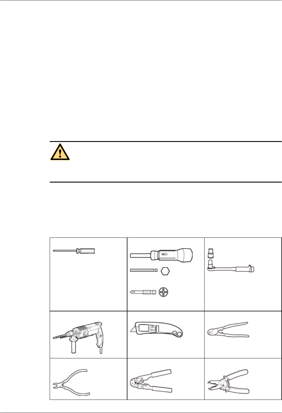
Tool Preparation
To install the APs, prepare tools listed in Table 2-1.
Table 2-1 Tools
Phillips screwdriver (M4) Torque screwdriver
3mm/5mm
(M3-M6)
Torque socket (M6)
Hammer drill (φ8) Utility knife Cable cutter
Diagonal pliers RJ45 crimping tool Wire stripper
Huawei AP8030DN & AP8130DN
Hardware Installation and Maintenance Guide 2 AP Installation
Issue 03 (2015-05-18) Huawei Proprietary and Confidential
Copyright © Huawei Technologies Co., Ltd.
11
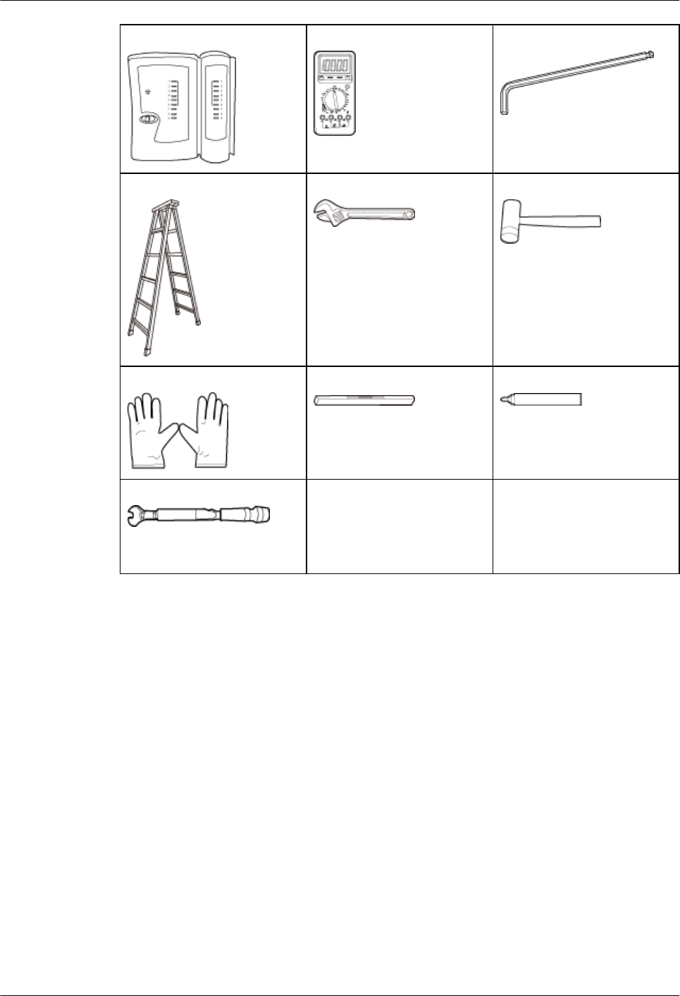
Network cable tester Multimeter Inner hexagon wrench (M6)
Ladder Adjustable wrench Rubber mallet
ESD gloves Level Marker
Torque wrench
(Use an N-type open-end
torque wrench.)
2.2 Installation Flowchart
Figure 2-1 shows the flowchart for installing an AP8130DN.
Huawei AP8030DN & AP8130DN
Hardware Installation and Maintenance Guide 2 AP Installation
Issue 03 (2015-05-18) Huawei Proprietary and Confidential
Copyright © Huawei Technologies Co., Ltd.
12
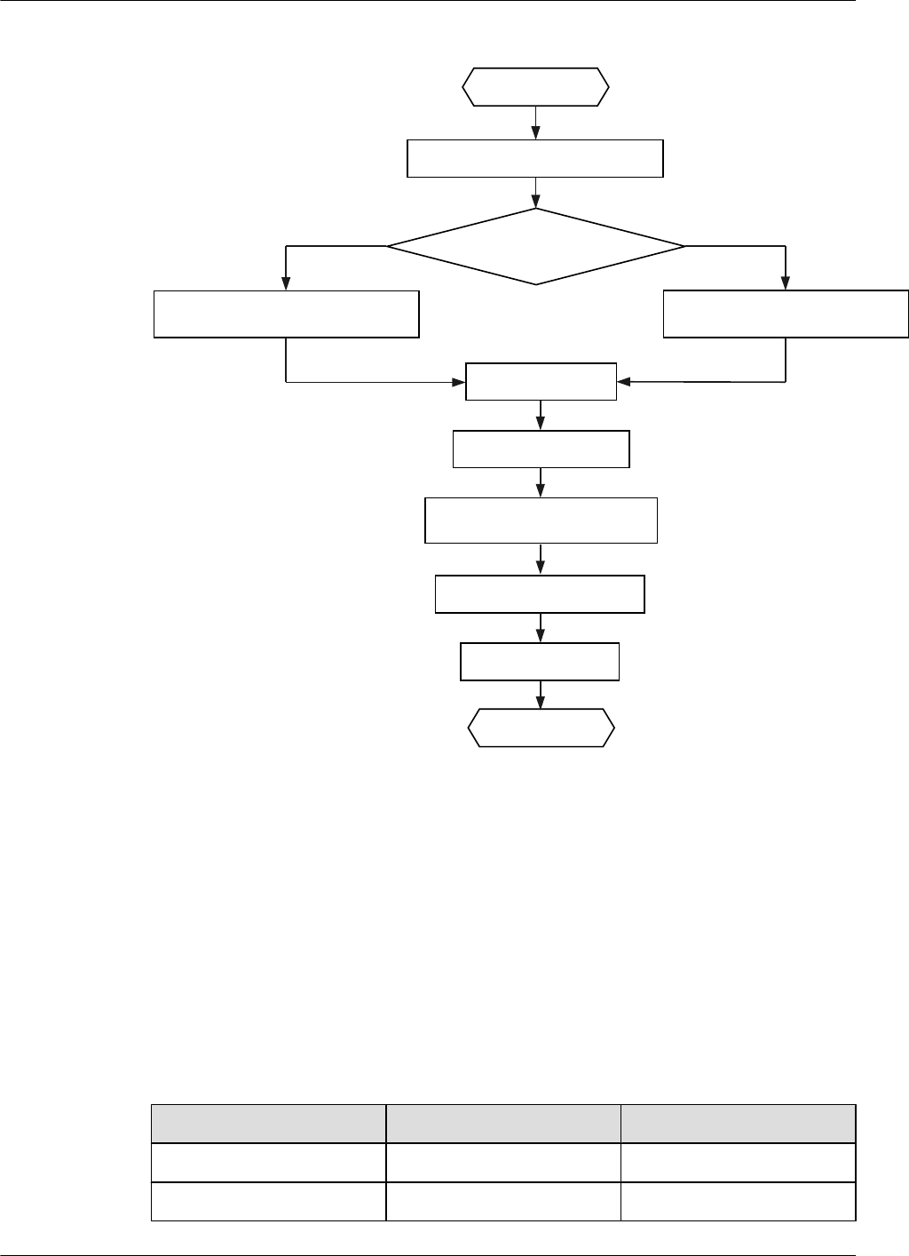
Figure 2-1 Installation flowchart
Determine the
installation location
Start
Check before installation
Fix the wall-mounting
Bracket against the wall
Fix the wall-mounting
Bracket against the pole
Install the AP
Connect the cable
Connect the security lock
to the lock hole
Power on the AP
Check after installation
End
Against the wall Against the pole
2.3 Unpacking the Equipment
Before unpacking the carton, ensure that the packing carton is intact and not damaged or soaked.
Stop unpacking if the equipment is rusted or soggy. Then, investigate causes and contact the
supplier.
After unpacking, check items in the carton against the packing list. If any item is missing, contact
the supplier or agent.
Usually, the packing carton contains all items listed in the packing list shown in Table 2-2.
Table 2-2 Packing list
No. Item Quantity
1AP device 1
2 Mounting bracket 1
Huawei AP8030DN & AP8130DN
Hardware Installation and Maintenance Guide 2 AP Installation
Issue 03 (2015-05-18) Huawei Proprietary and Confidential
Copyright © Huawei Technologies Co., Ltd.
13
No. Item Quantity
3PG connector 2
4 M4x12 hexagon socket head
cap screw
4
5 Expansion bolt 2
6 Hose clamp 2
7 OT terminal lM4: 2
lM6: 1
lM8: 1
8 Casting Adjustable-degree
solid1
1
9 Quick Start Guide 1
Pay attention to the following:
lOnly the AP8030DN carton contains the casting adjustable-degree solid.
lFigures in the document are for reference only and may be different from actual devices.
lRemove the protective film on the AP surface before installation to prevent electrostatic
discharge.
2.4 Determining the Installation Position
When determining the AP installation position, comply with the following rules:
lDo not install the AP in the place with high temperature, dust, noxious gas, or unstable
voltage, or in the place near flammable or explosive materials and interference sources such
as a large radar station, radio station, and transformer station.
lInstall the AP in a site that is free from leaking or dripping water, heavy dew, and humidity,
and take protective measures to prevent water from flowing into the equipment along the
cable.
lInstall the AP in a hidden position that does not affect daily lives and work of residents.
lMake the engineering design by fully considering such factors as hydrology, geology,
earthquake, electric power, and traffic. The selected site should comply with the
environment design specifications of communications equipment.
The AP8030DN and AP8130DN can be installed against a pole or a wall. The AP must be
installed by professional installation personnel, and the installation position is determined
according to the site survey.
Figure 2-2 and Figure 2-3 shows dimensions of the AP8030DN and AP8130DN.
Huawei AP8030DN & AP8130DN
Hardware Installation and Maintenance Guide 2 AP Installation
Issue 03 (2015-05-18) Huawei Proprietary and Confidential
Copyright © Huawei Technologies Co., Ltd.
14
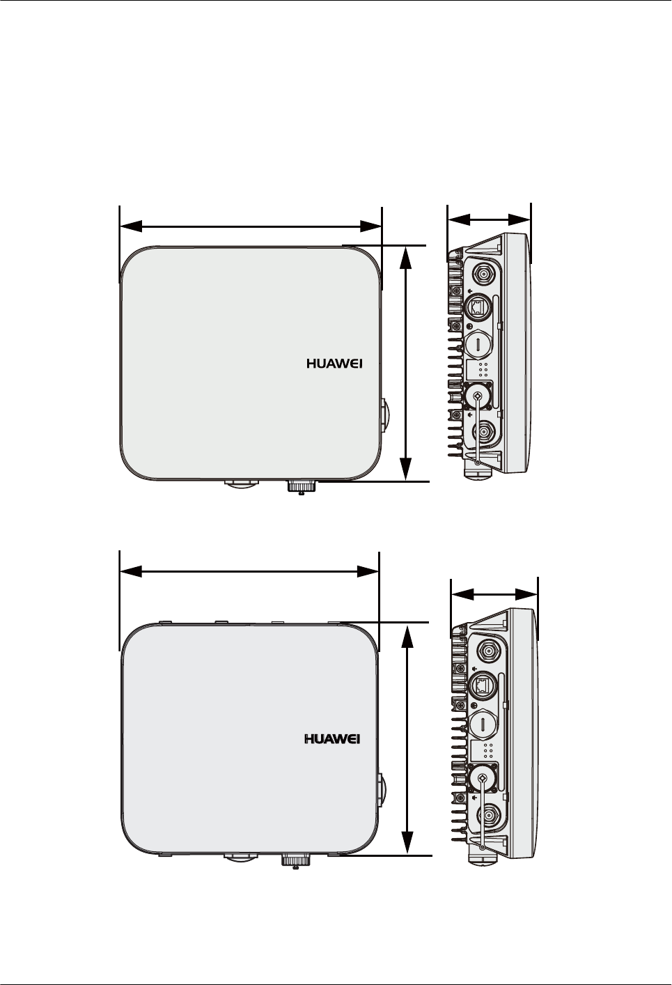
Figure 2-2 Dimensions of an AP8030DN (unit: mm)
290 100
*
*(3R( *( 6)3
6<6
**
/LQN$&7
:LUHOHVV
/LQN$&7
:LUHOHVV
/LQN$&7
260
Figure 2-3 Dimensions of an AP8130DN (unit: mm)
100
*
*(3R( *( 6)3
6<6
**
/LQN$&7
:LUHOHVV
/LQN$&7
:LUHOHVV
/LQN$&7
260
290
The AP8030DN and AP8130DN have the same space requirements. Figure 2-4 shows space
requirements for installing an AP8130DN.
Huawei AP8030DN & AP8130DN
Hardware Installation and Maintenance Guide 2 AP Installation
Issue 03 (2015-05-18) Huawei Proprietary and Confidential
Copyright © Huawei Technologies Co., Ltd.
15
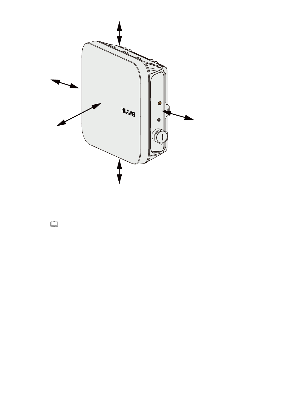
Figure 2-4 Space requirements for installing an AP8130DN (unit: mm)
'HIDXOW
≥500
≥1000
≥500
≥200
≥200
2.5 Installing the AP
NOTE
If the AP surface is covered with protective film, remove it before installation.
2.5.1 Wall Mounting
Wall mounting requires use of the mounting bracket and matching expansion bolts. The
AP8030DN installation requires use of the angle adjusting component but the AP8130DN does
not.
lInstalling an AP8030DN
lInstalling an AP8130DN
Installing an AP8030DN
1. Fix the mounting bracket to the wall, adjust the installation position, and use the marker to
mark the drilling positions where expansion bolts are installed, as shown in the following
figure.
Huawei AP8030DN & AP8130DN
Hardware Installation and Maintenance Guide 2 AP Installation
Issue 03 (2015-05-18) Huawei Proprietary and Confidential
Copyright © Huawei Technologies Co., Ltd.
16
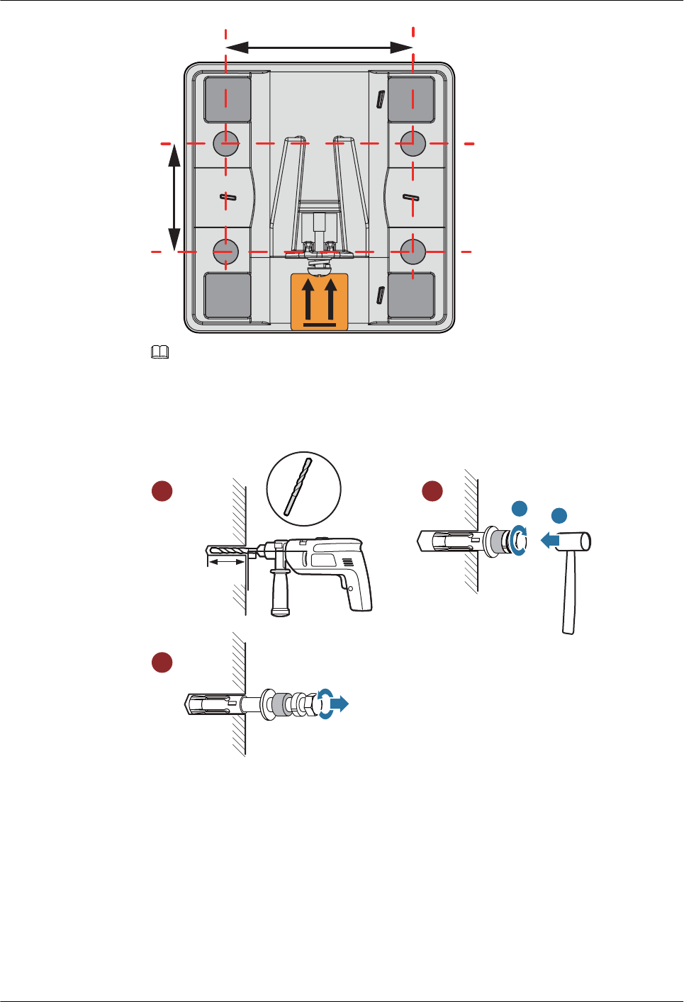
64mm
37mm
NOTE
Usually, the device can be fixed by installing two expansion bolts at diagonal positions.
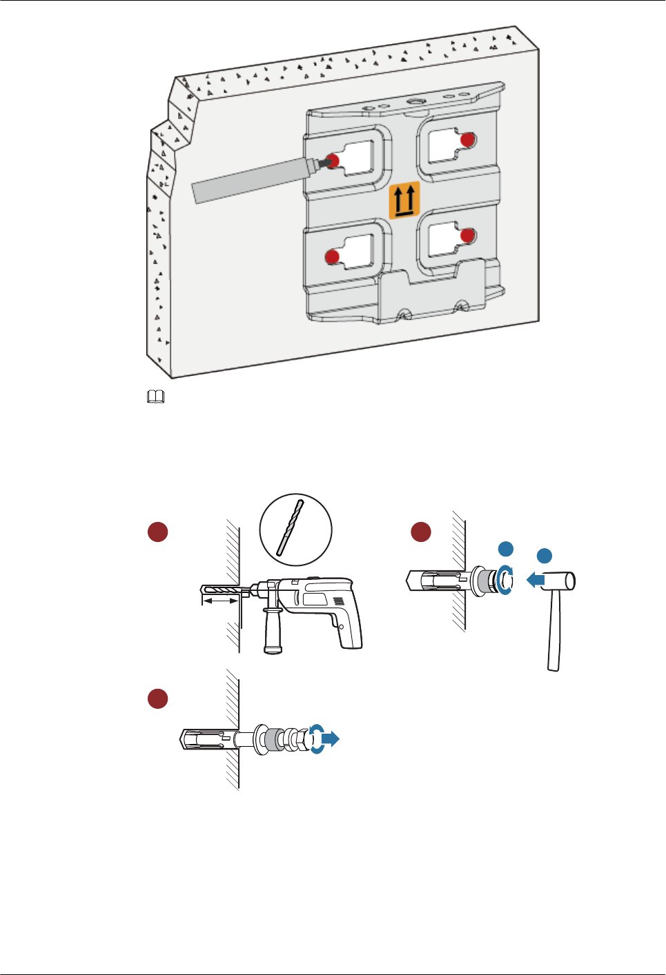
2. Use an 8 mm drill bit to drill 35 mm to 40 mm deep holes in the drilling positions and
hammer the expansion bolts into the installation holes until the flat washers are completely
attached to the wall. Then, remove the nut, spring washer, and flat washer in order.
90DŽ
Ø8
35mm~40mm
ab
1 2
3
3. Use four M4x12 hexagon socket head cap screws to fasten the AP-side module of the
mounting bracket to the AP.
Huawei AP8030DN & AP8130DN
Hardware Installation and Maintenance Guide 2 AP Installation
Issue 03 (2015-05-18) Huawei Proprietary and Confidential
Copyright © Huawei Technologies Co., Ltd.
17
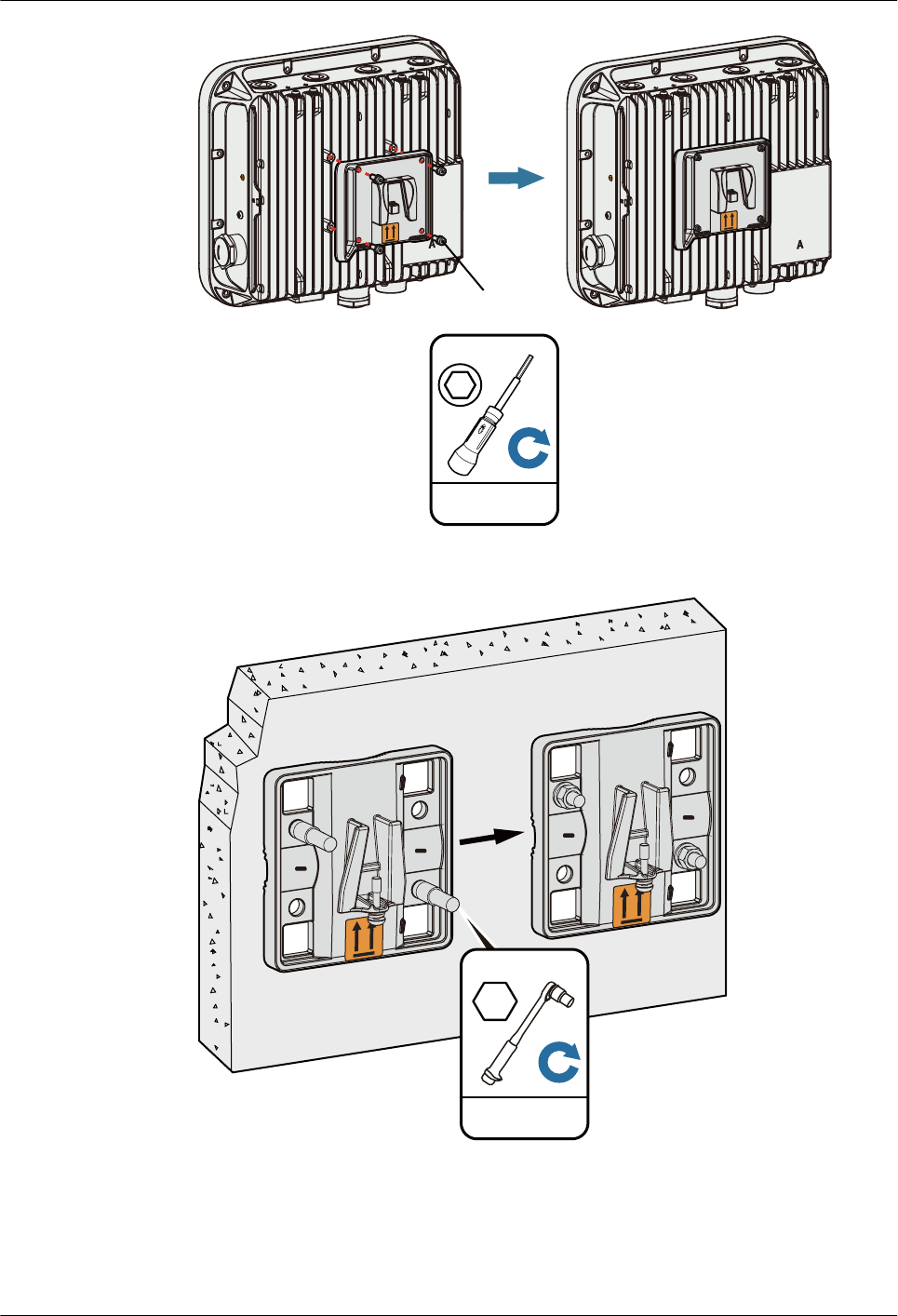
** ** * *
'HIDXOW
** ** * *
'HIDXOW
Hexagon socket
head cap screw
1N•m
M4
4. Hang the wall-side module of the mounting bracket on the expansion bolts and use a wrench
to fasten the flat washers, spring washers, and nuts in order.
5N•m
M6
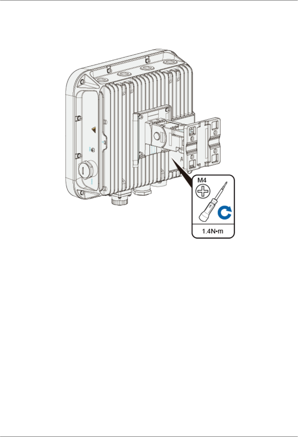
5. Hang the angle adjusting component on the mounting bracket and use a Phillips screwdriver
to tighten the screw at position 3, with a tightening torque of 1.4N*m.
Huawei AP8030DN & AP8130DN
Hardware Installation and Maintenance Guide 2 AP Installation
Issue 03 (2015-05-18) Huawei Proprietary and Confidential
Copyright © Huawei Technologies Co., Ltd.
18
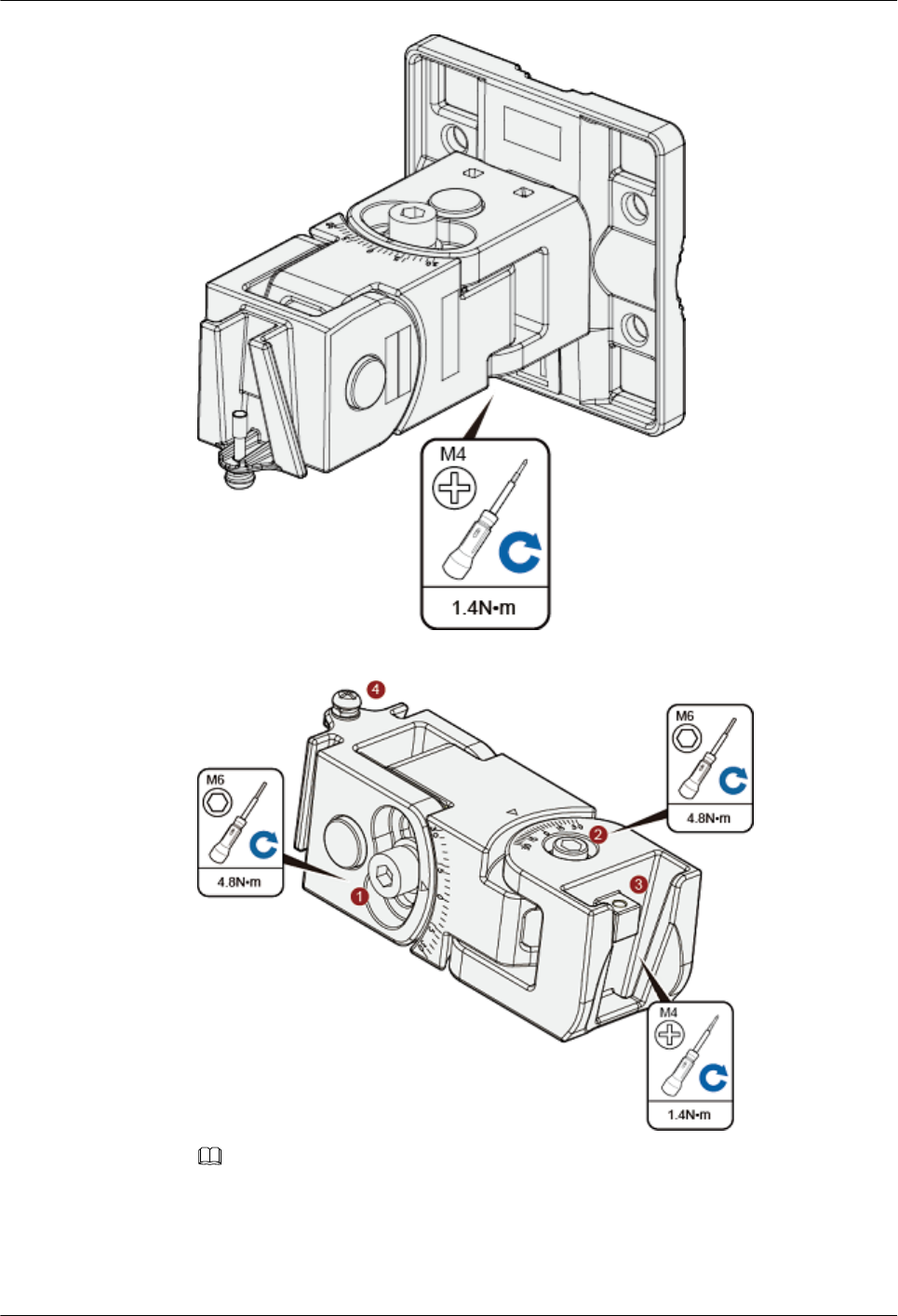
6. Loosen the screws at position 1 and position 2 using an M6 hex key.
NOTE
The screw at position 4 does not need to be loosened.
lTo adjust the horizontal angle of the AP, use the M6 hex key to remove the screw at
position 2, lift the angle adjusting component vertically, and adjust the angle adjusting
component horizontally.
Huawei AP8030DN & AP8130DN
Hardware Installation and Maintenance Guide 2 AP Installation
Issue 03 (2015-05-18) Huawei Proprietary and Confidential
Copyright © Huawei Technologies Co., Ltd.
19
lTo adjust the vertical angle of the AP, use the M6 hex key to loosen the screw at position
1, install the AP, and adjust the vertical angle with the weight of the AP.
7. Hang the AP with the AP-side mounting bracket module to the wall-side mounting bracket
module and tighten the screws to secure the AP.
Installing an AP8130DN
1. Fix the mounting bracket to the wall, adjust the installation position, and use the marker to
mark the drilling positions where expansion bolts are installed, as shown in the following
figure.
Huawei AP8030DN & AP8130DN
Hardware Installation and Maintenance Guide 2 AP Installation
Issue 03 (2015-05-18) Huawei Proprietary and Confidential
Copyright © Huawei Technologies Co., Ltd.
20
NOTE
Usually, the device can be fixed by installing two expansion bolts at diagonal positions.
2. Use an 8 mm drill bit to drill 35 mm to 40 mm deep holes in the drilling positions and
hammer the expansion bolts into the installation holes until the flat washers are completely
attached to the wall. Then, remove the nut, spring washer, and flat washer in order.
90DŽ
Ø8
35mm~40mm
ab
1 2
3
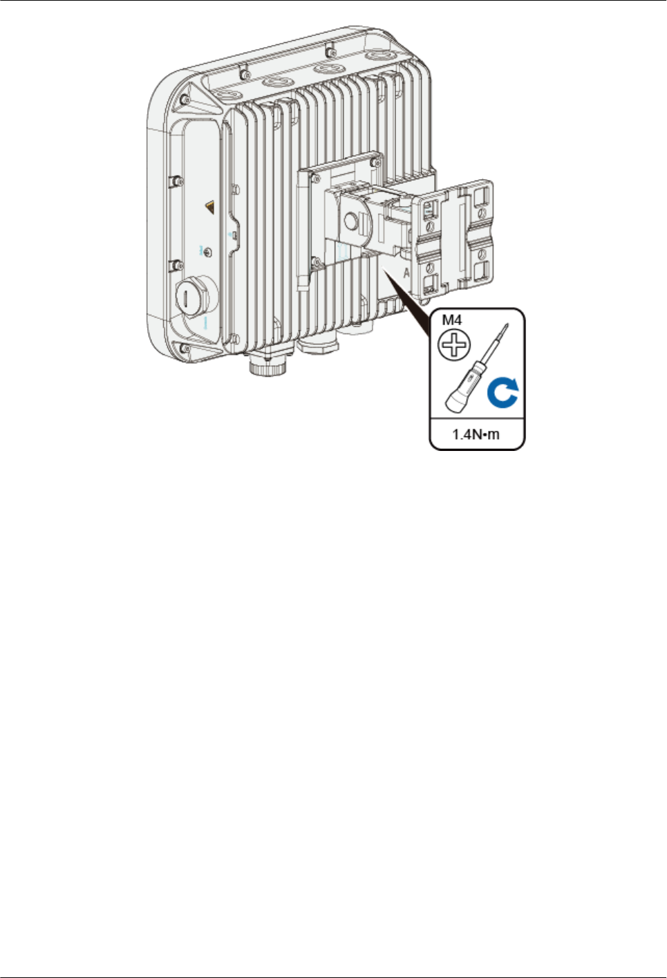
3. Use four M4x12 hexagon socket head cap screws to fasten the AP-side module of the
mounting bracket to the AP.
Huawei AP8030DN & AP8130DN
Hardware Installation and Maintenance Guide 2 AP Installation
Issue 03 (2015-05-18) Huawei Proprietary and Confidential
Copyright © Huawei Technologies Co., Ltd.
21
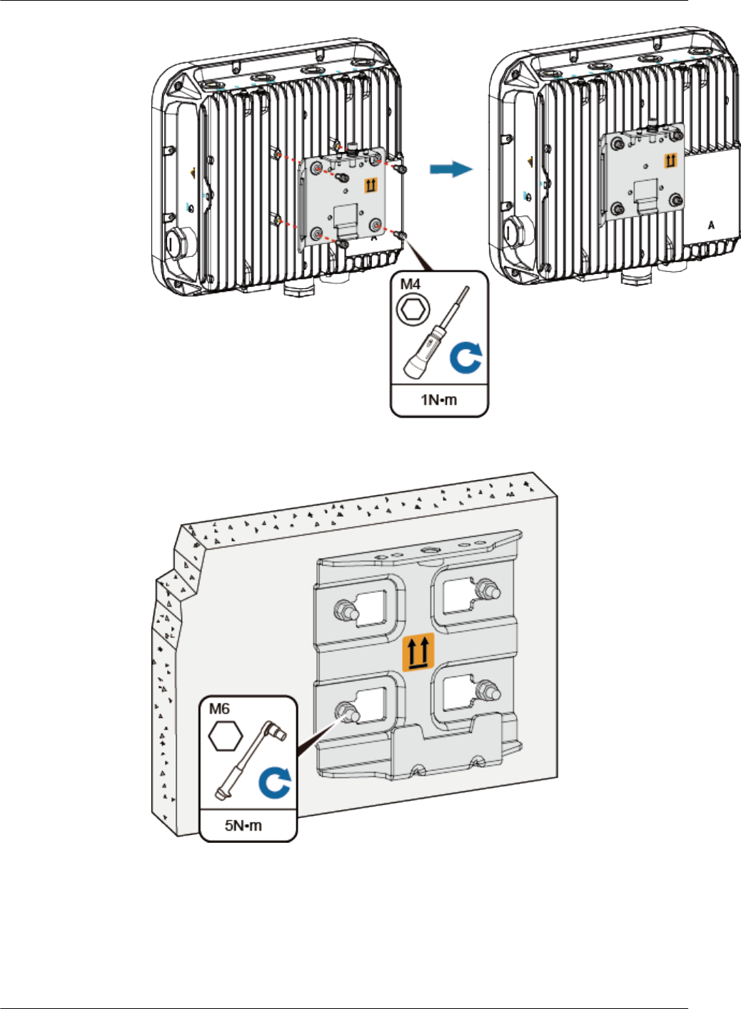
4. Hang the wall-side module of the mounting bracket on the expansion bolts and use a wrench
to fasten the flat washers, spring washers, and nuts in order.
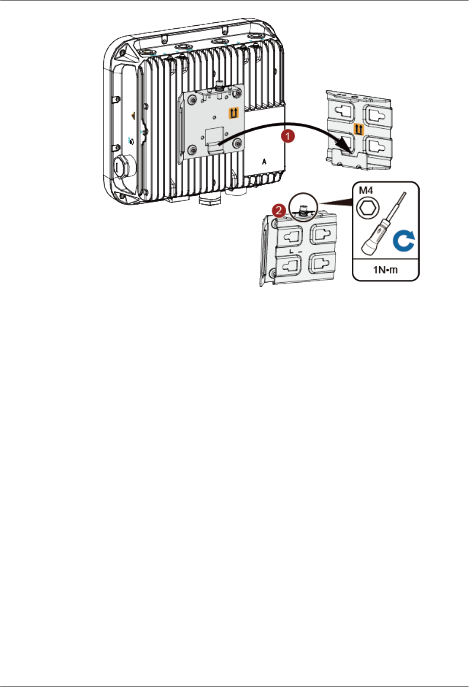
5. Hang the AP with the AP-side mounting bracket module to the wall-side mounting bracket
module and tighten the screws to secure the AP.
Huawei AP8030DN & AP8130DN
Hardware Installation and Maintenance Guide 2 AP Installation
Issue 03 (2015-05-18) Huawei Proprietary and Confidential
Copyright © Huawei Technologies Co., Ltd.
22
2.5.2 Pole Mounting
An outdoor AP must be installed on a pole with a diameter of 48 mm to 114 mm and the thickness
must be at least 2.5 mm. The AP8030DN installation requires use of the angle adjusting
component but the AP8130DN does not.
lInstalling an AP8030DN
lInstalling an AP8130DN
Installing an AP8030DN
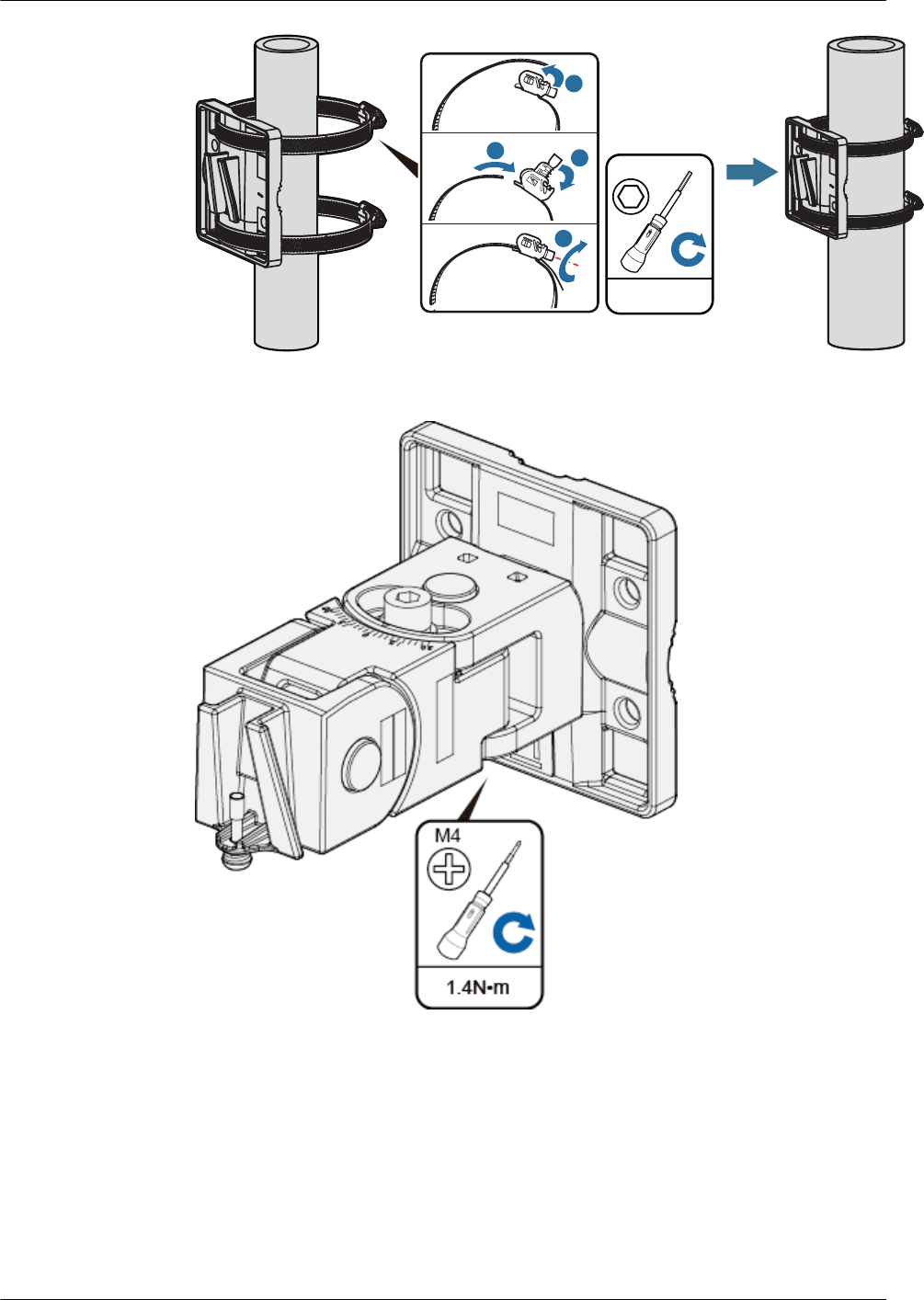
1. Determine the AP installation position and attach the mounting bracket on the pole using
the hose clamp.
a. Use the M6 hex torque screwdriver to loosen screws on the hose clamp and lift the
lid.
b. Slide the hose clamp through the hole of the mounting bracket, attach it to the pole,
and close the hose clamp.
c. Close the lid.
d. Use the hex torque screwdriver to tighten the screws with a torque of 5 N•m.
Huawei AP8030DN & AP8130DN
Hardware Installation and Maintenance Guide 2 AP Installation
Issue 03 (2015-05-18) Huawei Proprietary and Confidential
Copyright © Huawei Technologies Co., Ltd.
23
5N•m
M6
a
bc
d
2. Hang the angle adjusting component on the mounting bracket and use a Phillips screwdriver
to tighten the screw at position 3, with a tightening torque of 1.4N•m.
3. Loosen the screws at position 1 and position 2 using an M6 hex key.
Huawei AP8030DN & AP8130DN
Hardware Installation and Maintenance Guide 2 AP Installation
Issue 03 (2015-05-18) Huawei Proprietary and Confidential
Copyright © Huawei Technologies Co., Ltd.
24
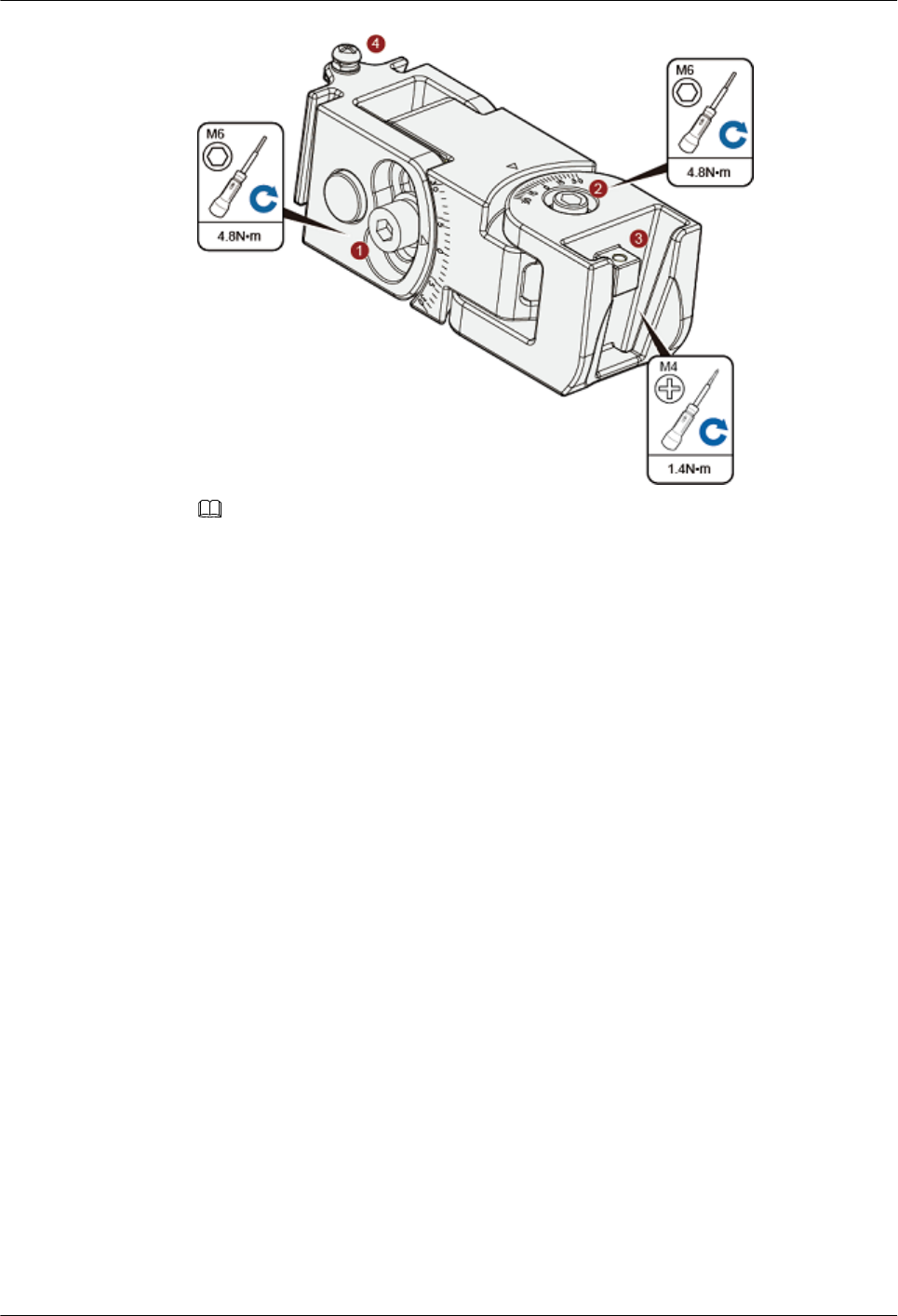
NOTE
The screw at position 4 does not need to be loosened.
lTo adjust the horizontal angle of the AP, use the M6 hex key to remove the screw at
position 2, lift the angle adjusting component vertically, and adjust the angle adjusting
component horizontally.
lTo adjust the vertical angle of the AP, use the M6 hex key to loosen the screw at position
1, install the AP, and adjust the vertical angle with the weight of the AP.
4. Hang the AP with the AP-side mounting bracket module to the wall-side mounting bracket
module and tighten the screws to secure the AP.
Huawei AP8030DN & AP8130DN
Hardware Installation and Maintenance Guide 2 AP Installation
Issue 03 (2015-05-18) Huawei Proprietary and Confidential
Copyright © Huawei Technologies Co., Ltd.
25
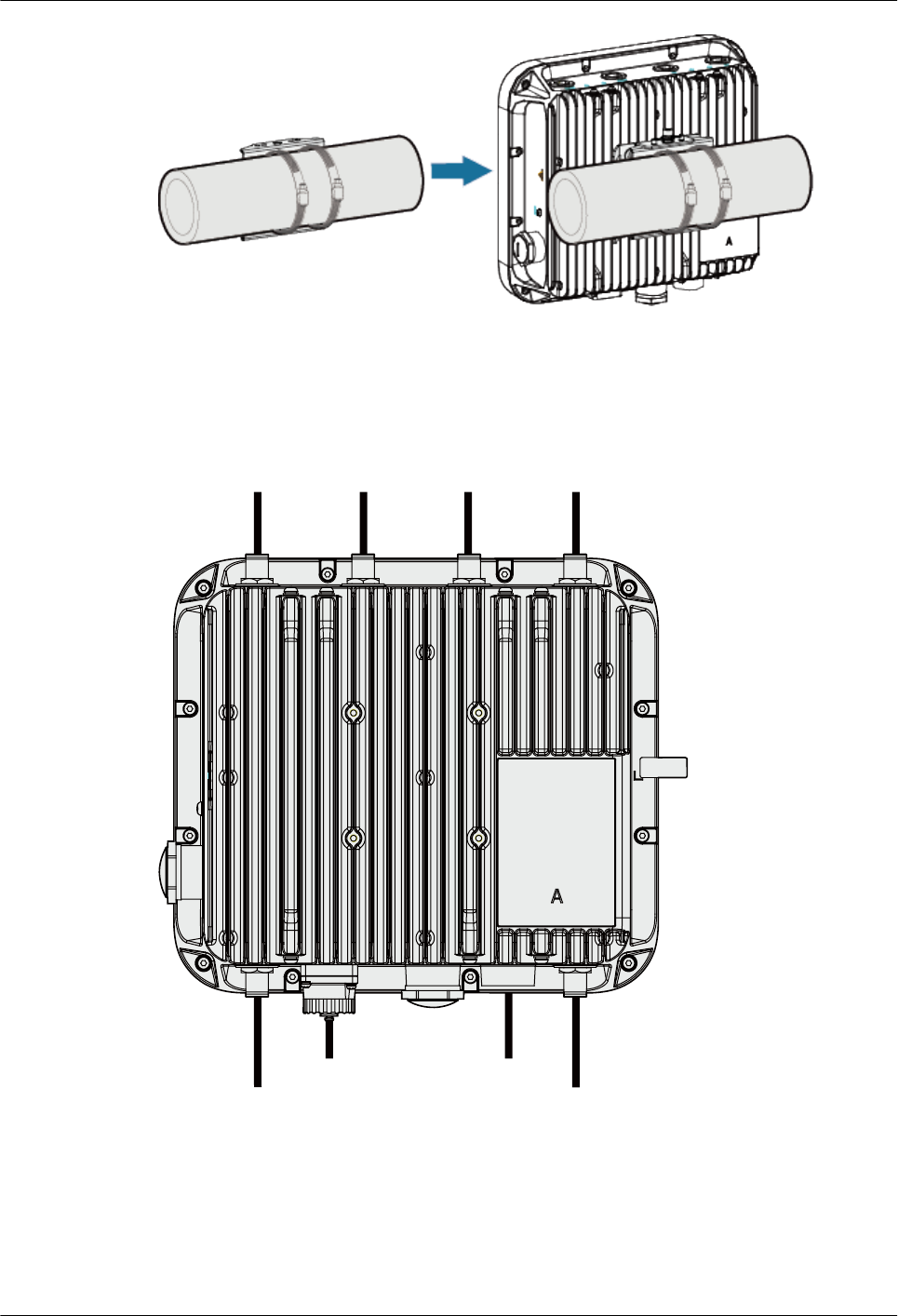
Installing an AP8130DN
Mounting an AP on a vertical pole
1. Determine the AP installation position and attach the mounting bracket on the pole using
the hose clamp.
a. Use the M6 hex torque screwdriver to loosen screws on the hose clamp and lift the
lid.
b. Slide the hose clamp through the hole of the mounting bracket, attach it to the pole,
and close the hose clamp.
c. Close the lid.
d. Use the hex torque screwdriver to tighten the screws with a torque of 5 N•m.
Huawei AP8030DN & AP8130DN
Hardware Installation and Maintenance Guide 2 AP Installation
Issue 03 (2015-05-18) Huawei Proprietary and Confidential
Copyright © Huawei Technologies Co., Ltd.
26
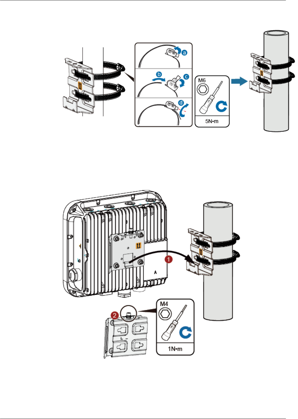
2. Hang the AP with the AP-side mounting bracket module to the wall-side mounting bracket
module and tighten the screws to secure the AP.
Mounting an AP on a horizontal pole
The procedure for installing the AP against a horizontal pole is similar to the procedure for
installing the AP against a vertical pole.
Huawei AP8030DN & AP8130DN
Hardware Installation and Maintenance Guide 2 AP Installation
Issue 03 (2015-05-18) Huawei Proprietary and Confidential
Copyright © Huawei Technologies Co., Ltd.
27
2.6 Connecting Cables
Figure 2-5 AP8130DN external cable arrangement
Feed line Feed line Feed line Feed line
Feed line Feed line
Optical fiber Network cable
2.6.1 Connecting RF Cables
Huawei AP8030DN & AP8130DN
Hardware Installation and Maintenance Guide 2 AP Installation
Issue 03 (2015-05-18) Huawei Proprietary and Confidential
Copyright © Huawei Technologies Co., Ltd.
28
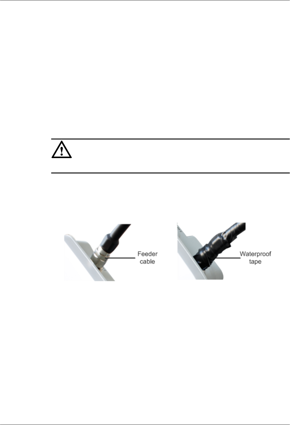
RF cable deployment requirements
lIt is recommended that you connect a 50 ohm RF load to an idle antenna interface and wrap
the RF load with insulation tape and waterproof tape. Huawei offers 50 ohm RF loads for
you to purchase.
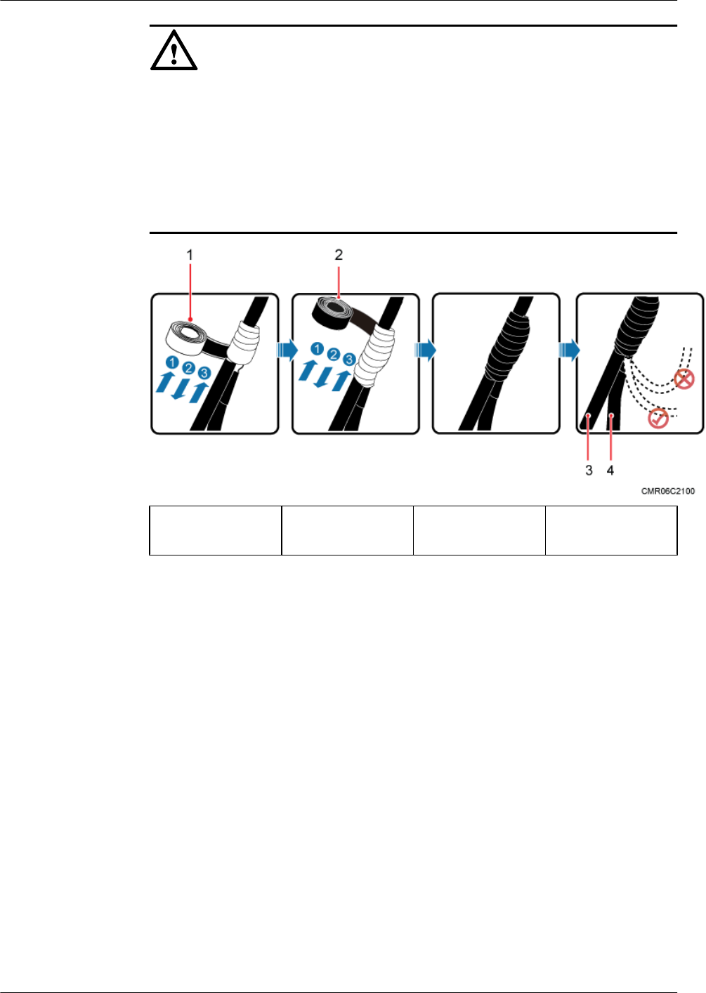
lWrap the RF cable using one-layer PVC insulation tape, three-layer waterproof adhesive
tape, and then three-layer PVC insulation tape.
lBefore wrapping the waterproof tape, stretch the tape evenly until the tape turns 1/2 as wide
as before. Wrap each layer of tape tightly and ensure that each layer covers more than 50%
of the layer below it.
lWrap the three-layer tape from bottom to top, from top to bottom, and then from bottom
to top.
lBend radius requirements: RG-8U RF cable: > 150 mm; 1/2" RF cable: > 50 mm; 7/8" RF
cable: > 250 mm. One inch equals to 25.4 mm.
NOTICE
Tighten the nut of the AP's RF connector with a maximum torque of 1.2 N•m.
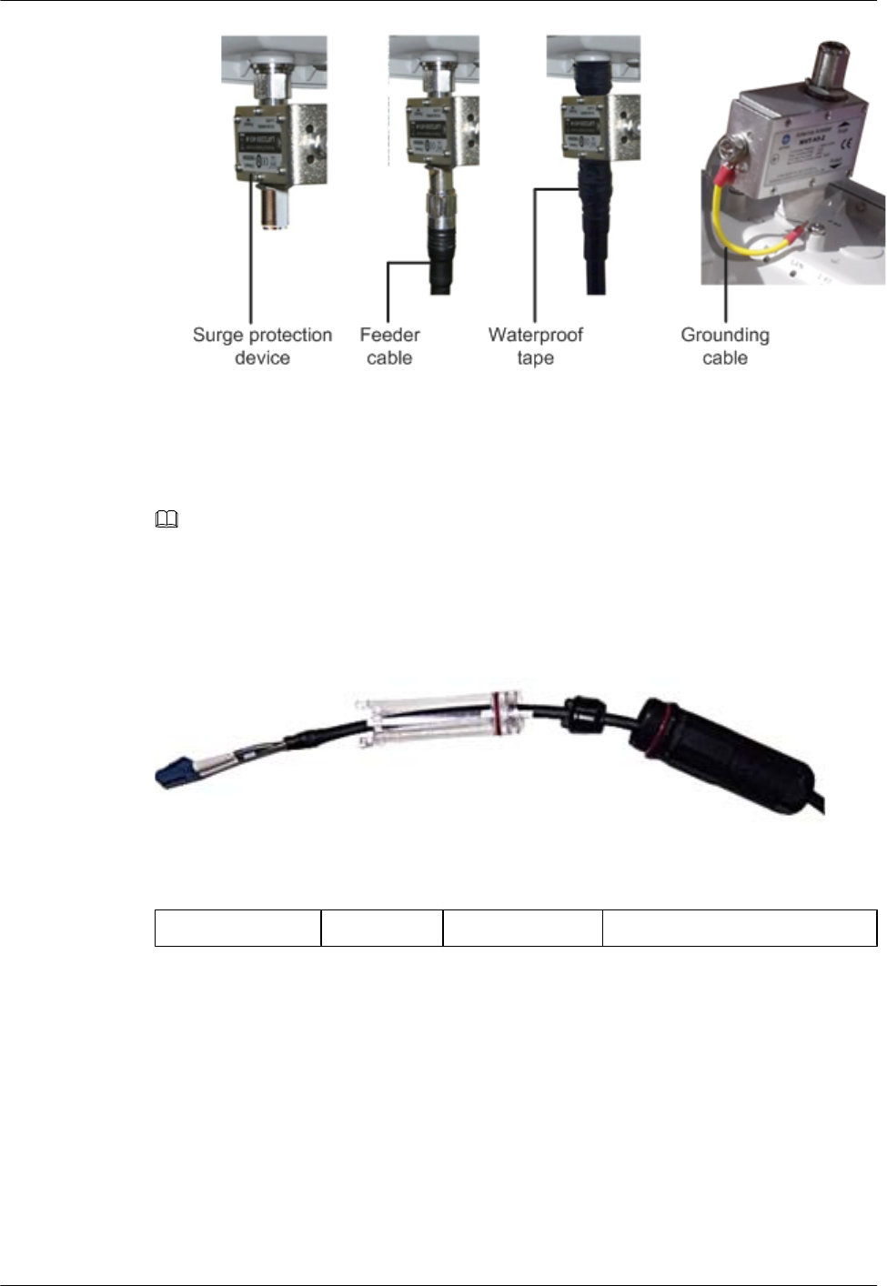
RF cable connections
1. Antenna interfaces of the AP provides a 5 KA surge protection capability. Generally, no
additional surge protective device needs to be installed, and the RF cables are directly
connected to the antenna interfaces.
2. If a higher surge protection capability is required, the customer can purchase a surge
protective device. When installing the surge protective device, ensure that it is connected
to a ground cable.
Huawei AP8030DN & AP8130DN
Hardware Installation and Maintenance Guide 2 AP Installation
Issue 03 (2015-05-18) Huawei Proprietary and Confidential
Copyright © Huawei Technologies Co., Ltd.
29
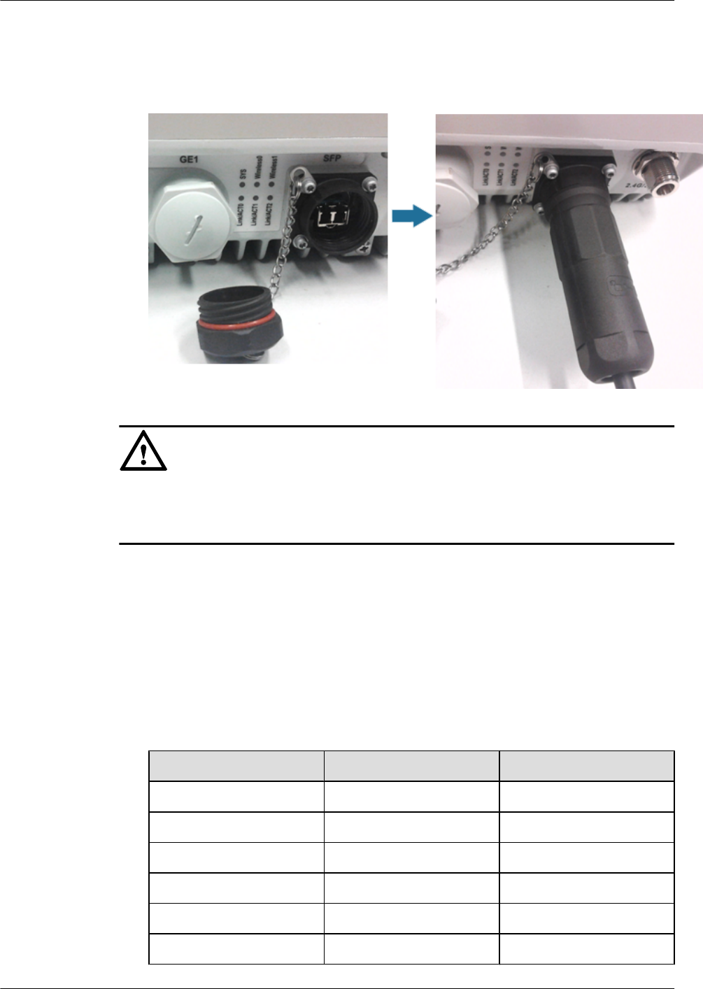
2.6.2 Connecting Optical Fibers and Network Cables
Connecting optical fibers
NOTE
The device can transmit upstream data over optical fibers. The optical fiber is connected to the device using
fiber connectors (purchased independently).
The following figure shows components of an optical fiber connector.
Figure 2-6 Components of an optical fiber connector
(1) Optical fiber (2) Support (3) Rubber ring (4) External connector shell
1. Select an optical cable of a proper length based on onsite cabling.
2. Remove the waterproof block from the rubber ring of the connector, as shown in the
following figure.
Huawei AP8030DN & AP8130DN
Hardware Installation and Maintenance Guide 2 AP Installation
Issue 03 (2015-05-18) Huawei Proprietary and Confidential
Copyright © Huawei Technologies Co., Ltd.
30
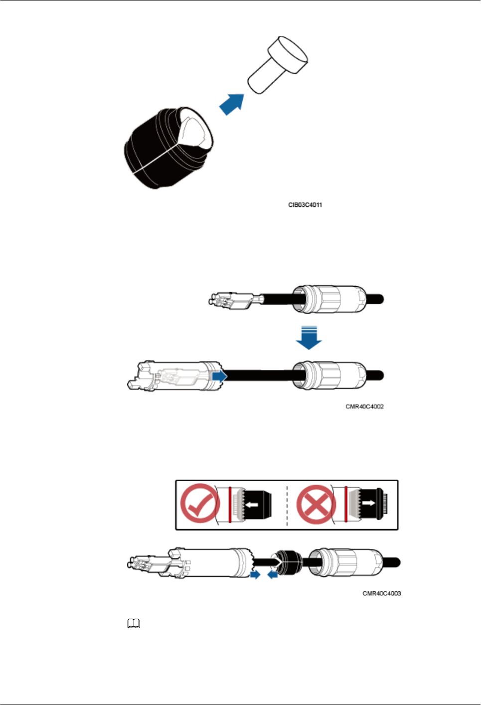
Figure 2-7 Removing the waterproof block
3. Assemble the connector on the optical fiber.
a. Assemble the external connector shell and support, as shown in the following figure.
Figure 2-8 Assembling the connector (1)
b. Put the rubber ring on the optical fiber and insert it into the support in compliance
with the direction indicated on the ring, as shown in the following figure.
Figure 2-9 Assembling the connector (2)
NOTE
Ensure that the arrow on the rubber ring points to the support.
4. Remove the sealing cover of the optical fiber port on the device and insert the optical fiber
into the port. Turn the support to find the correct optical fiber installation slot and push the
support forward (together with the rubber ring) until the optical fiber is installed to the
Huawei AP8030DN & AP8130DN
Hardware Installation and Maintenance Guide 2 AP Installation
Issue 03 (2015-05-18) Huawei Proprietary and Confidential
Copyright © Huawei Technologies Co., Ltd.
31
correct position. Rotate the external connector shell clockwise until the red ring is not
visible, as shown in the following figure.
Figure 2-10 Connecting optical fibers
NOTICE
lConnect the optical fiber correctly; otherwise, the optical fiber may be damaged.
lBundle the optical fibers with binding tapes every 1 m.
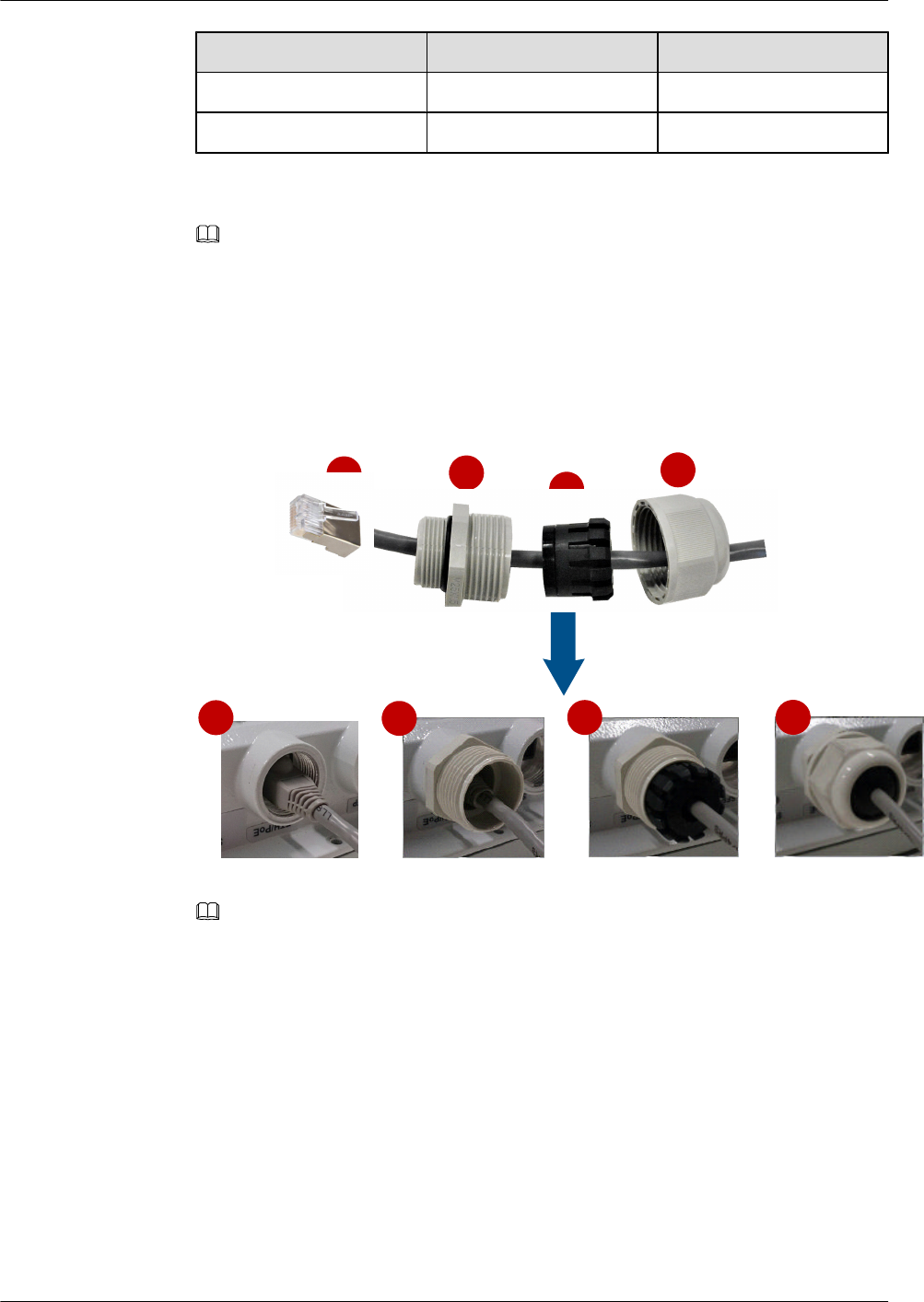
Connecting network cables
1. Use a shielded straight-through cable. Cut the cable into a proper length based on the
distance between the AP and the PSE device, strip the cables on both ends, and crimp the
wires into RJ45 connectors.
2. Make a network cable onsite according to pin assignment in Table 2-3. Otherwise, the
communication quality is affected even if devices can be connected.
Table 2-3 Pin assignment
X1 Pin Wire Color X2 Pin
1White and orange 1
2 Orange 2
3 White and green 3
4 Blue 4
5 White and blue 5
6 Green 6
Huawei AP8030DN & AP8130DN
Hardware Installation and Maintenance Guide 2 AP Installation
Issue 03 (2015-05-18) Huawei Proprietary and Confidential
Copyright © Huawei Technologies Co., Ltd.
32
X1 Pin Wire Color X2 Pin
7White and brown 7
8 Brown 8
NOTE
Actually, APs use shielded straight-through network cables, which are connected in the same way
as unshielded network cables.
3. Put the network cable through waterproof PG connectors. Connect the RJ45 connector to
the ETH/PoE interface on the AP and secure the waterproof PG connector. See figures b,
c, and d.
Figure 2-11 Connecting network cables
bcd
a
d
c
b
a
NOTE
lThe network cables used are shielded straight-through cables.
lEnsure that the RJ45 connector is correctly connected to the AP. Otherwise, the network cable
may be damaged. Before removing the network cable from the AP, remove the waterproof PG
connector first and then remove the RJ45 connector.
lThe cable cannot exceed 100 meters.
2.6.3 Connecting Ground Cables
Grounding is a key step in device installation. The ground cable of a device must be correctly
connected to protect the device from lightning, electromagnetic interference, and electrostatic
charges. Outdoor APs support built-in surge protection on all interfaces, but the surge protection
works only when the outdoor APs are grounded.
Huawei AP8030DN & AP8130DN
Hardware Installation and Maintenance Guide 2 AP Installation
Issue 03 (2015-05-18) Huawei Proprietary and Confidential
Copyright © Huawei Technologies Co., Ltd.
33
Requirements for laying out ground cables
lThe ground cables must be connected to a group of ground bars.
lThe bend radius of the ground cables must be larger than or equal to five times the cable
diameter.
lThe ground cables must be buried underground or routed indoors and cannot be led into
the equipment room aerially.
lBoth ends of the external conductor of the coaxial cable and those of the shield layer of the
shielded cable should have good electric contact with the metal shell of the equipment they
connect to.
lGround cables must be separated from signal cables to reduce interference between them.
lDo not add any switch or fuse on the ground cable.
lDo not use another device for an electrical connection with the ground cable.
lAll metal components in the shell must be securely connected to the ground terminal.
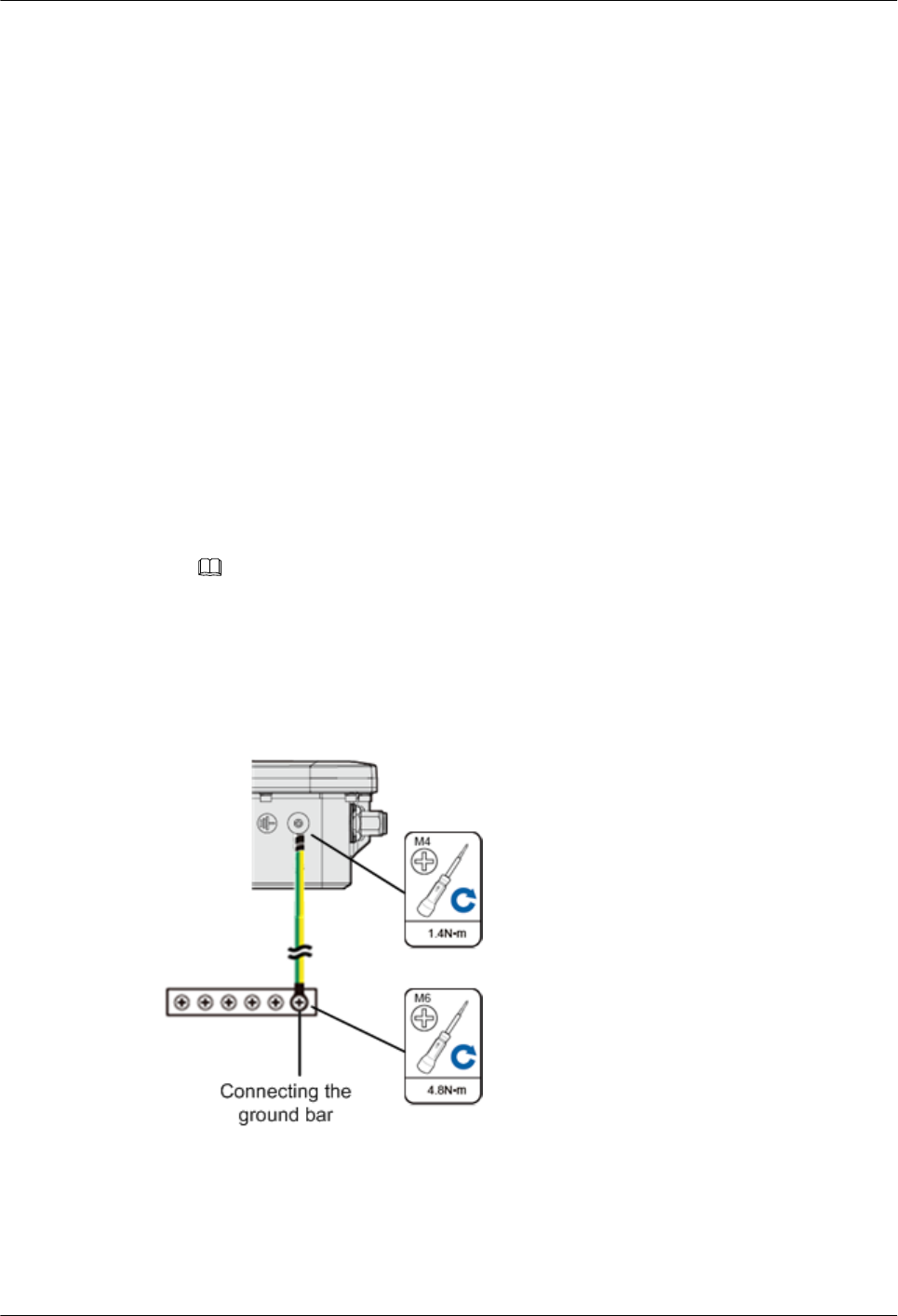
Ground cable connections
1. Cut the ground cable into a proper length and use the M4 OT terminal to connect to the
AP. The OT terminal used to connect to the ground terminal depends on site requirements.
NOTE
To tighten the screws with a torque on the ground bar,
lM4: 1.4N•m.
lM6: 4.8N•m.
lM8: 12N•m.
2. The equipment functions properly when the ground resistance is less than 10 ohms.
Grounding shielded network cables
Using shielded network cables can improve surge protection performance of the AP. To connect
the cable, cut the shield layer open, connect the cable to the ground clip, and wrap the cable with
waterproof and ESD tapes.
Huawei AP8030DN & AP8130DN
Hardware Installation and Maintenance Guide 2 AP Installation
Issue 03 (2015-05-18) Huawei Proprietary and Confidential
Copyright © Huawei Technologies Co., Ltd.
34
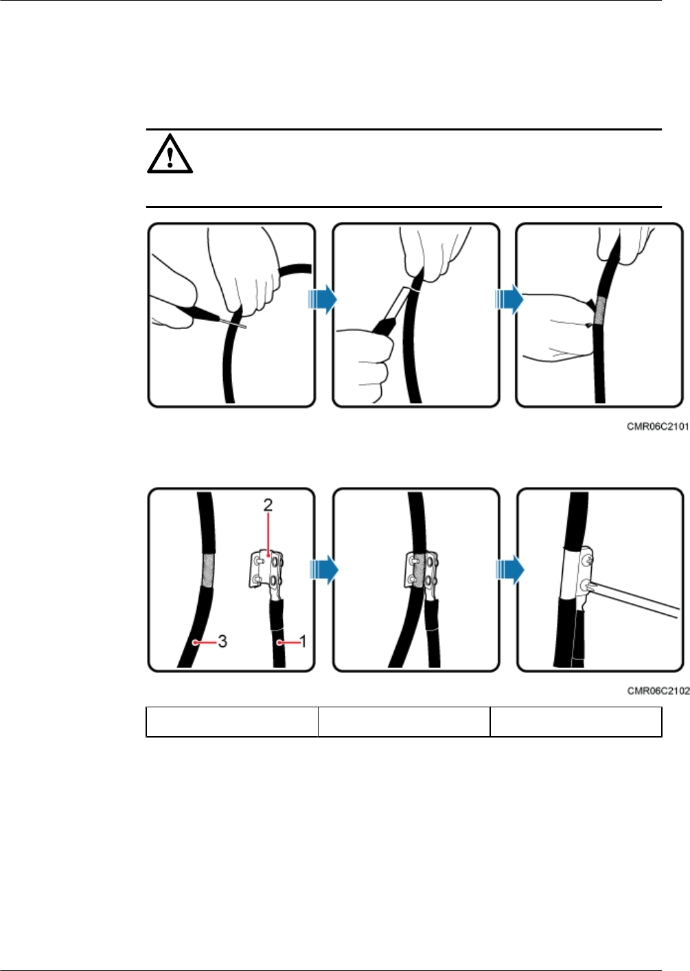
1. Determine the position for installing the ground clip on the cable based on the actual cable
route.
2. Use a utility knife to strip the sheath off the network cable for about 32 mm (1.26in.) to
expose the shield layer.
NOTICE
Do not damage the shield layer when stripping the sheath off the cable.
3. Install the ground clip on the shield layer of the cable, and then use a screwdriver to tighten
the screws on the ground clip.
(1) Ground cable (2) Ground clip (3) Network cable
4. Wrap three layers of waterproof tape and three layers of polyvinyl chloride (PVC) insulation
tape at the ground clip.
Huawei AP8030DN & AP8130DN
Hardware Installation and Maintenance Guide 2 AP Installation
Issue 03 (2015-05-18) Huawei Proprietary and Confidential
Copyright © Huawei Technologies Co., Ltd.
35
NOTICE
lWrap the tape around the clip from bottom up, then from top down, and finally from
bottom up. Do not cut the tape until all the three layers of the tape are already wrapped.
When wrapping tape, be sure that each layer of tape overlaps more than 50% of the
preceding layer.
lThe degree between the ground cable and the network cable cable is not greater than
15°. When the network cable is routed vertically, the ground cable must be routed
downwards.
(1) Waterproof tape (2) PVC insulation
tape
(3) Network cable (4) Ground cable
5. Connect the ground cable to an external ground bar.
2.6.4 Installing Outdoor Antennas
Two types of outdoor antennas are available: directional outdoor antenna and omnidirectional
outdoor antenna. Omnidirectional antennas can be directly installed on APs.
Installing a directional outdoor antenna against a pole
Pay attention to the following points when installing a directional antenna:
1. An outdoor antenna must be installed on a pole with a diameter of 30 mm to 50 mm and
the thickness must be at least 2.5 mm. A 50 mm diameter pole made of round steel is usually
used.
2. Weld the lightning rod on the top of the antenna pole.
3. Install the antenna pole on a parapet or concrete bed on the roof of the building.
4. Use a 40 mm x 4 mm flat steel to connect the antenna pole to an earth mat.
5. Secure the directional outdoor antenna on the pole with an antenna support.
6. Keep the pole vertical to the ground during the installation.
Huawei AP8030DN & AP8130DN
Hardware Installation and Maintenance Guide 2 AP Installation
Issue 03 (2015-05-18) Huawei Proprietary and Confidential
Copyright © Huawei Technologies Co., Ltd.
36
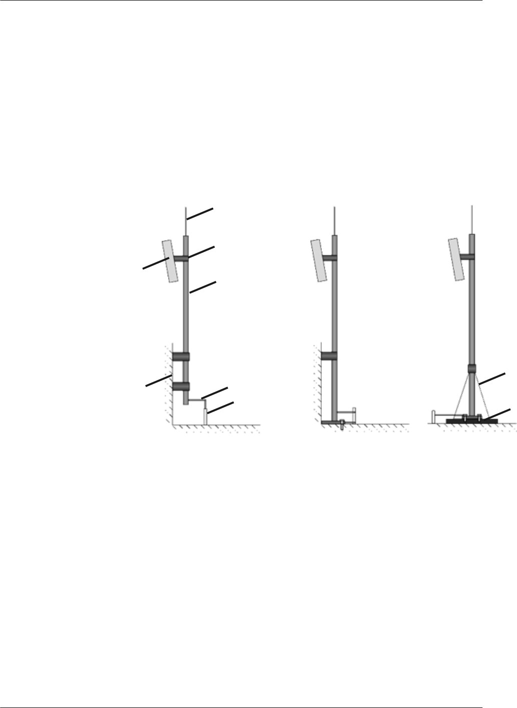
See Figure 2-12 below for how a directional outdoor antenna is installed on a pole.
lIf the roof of the building is surrounded by parapets of no less than 1.2 m high, fix the pole
on a parapet with expansion screws, and then fix the directional outdoor antenna on the
pole with an antenna support.
lIf the roof of the building is surrounded by parapets of less than 1.2 m high, fix the pole on
a parapet and on the ground with expansion screws, and then fix the directional outdoor
antenna on the pole with an antenna support.
lIf there is no parapet around the roof, fix the pole on the ground or a concrete bed with
expansion screws and steel wires, and then fix the directional outdoor antenna on the pole
with an antenna support.
Figure 2-12 Installing a directional outdoor antenna against a pole
Outdoor
directional
antenna
Parapet
Lightning rod
Antenna support
Pole
Flat steel
Connected to
the earth mat
Parapet height > 1.2 m Parapet height < 1.2 m No parapet
Steel wire
Concrete
bed
Figure 2-13 shows outdoor AP installation scenarios.
Huawei AP8030DN & AP8130DN
Hardware Installation and Maintenance Guide 2 AP Installation
Issue 03 (2015-05-18) Huawei Proprietary and Confidential
Copyright © Huawei Technologies Co., Ltd.
37
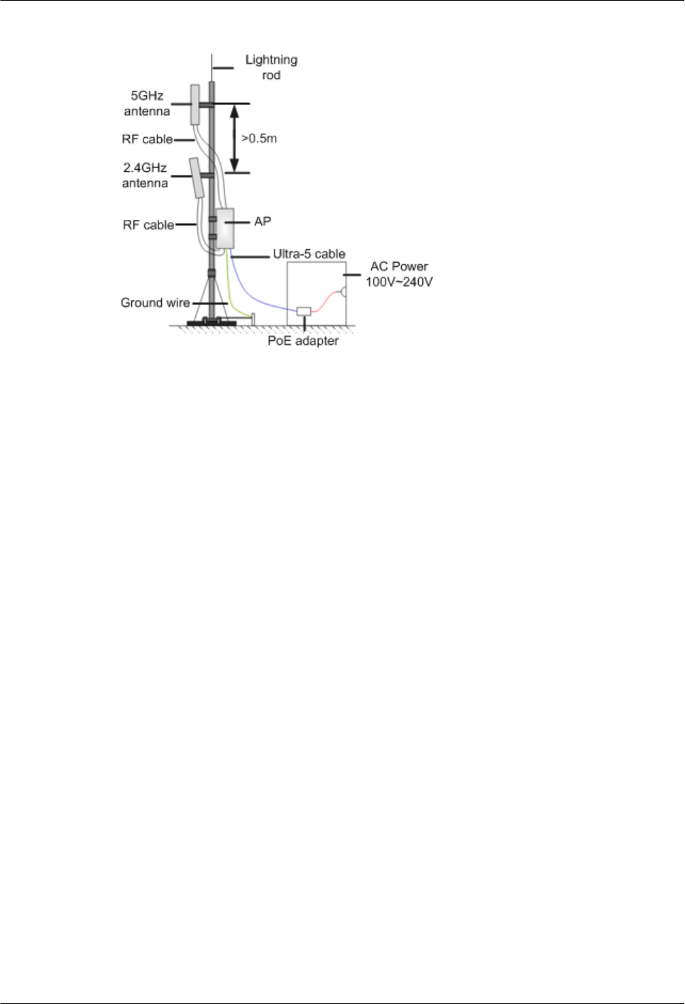
Figure 2-13 Outdoor AP installation scenarios
Installing an omnidirectional outdoor antenna against a pole
Pay attention to the following points when installing an omnidirectional antenna:
1. An outdoor antenna must be installed on a pole with a diameter of 30 mm to 50 mm and
the thickness must be at least 2.5 mm. A 50 mm diameter pole made of round steel is usually
used.
2. The top of pole must be aligned with the hose clamp at the bottom of the antenna.
3. The antenna must be installed at a proper height to provide sufficient signal coverage, and
the top of the antenna must be within the 45 degrees protection angle of the lighting rod.
4. Do no weld a lightning rod directly on the antenna pole (there should not be metal subjects
within 1 m around an omnidirectional antenna). Instead, install an independent lightning
rod between two omnidirectional antenna poles. Adjust the height of the lightning rod to
ensure that the omnidirectional antennas are covered in the protection angle.
Figure 2-14 shows installation of an omnidirectional outdoor antenna.
Huawei AP8030DN & AP8130DN
Hardware Installation and Maintenance Guide 2 AP Installation
Issue 03 (2015-05-18) Huawei Proprietary and Confidential
Copyright © Huawei Technologies Co., Ltd.
38
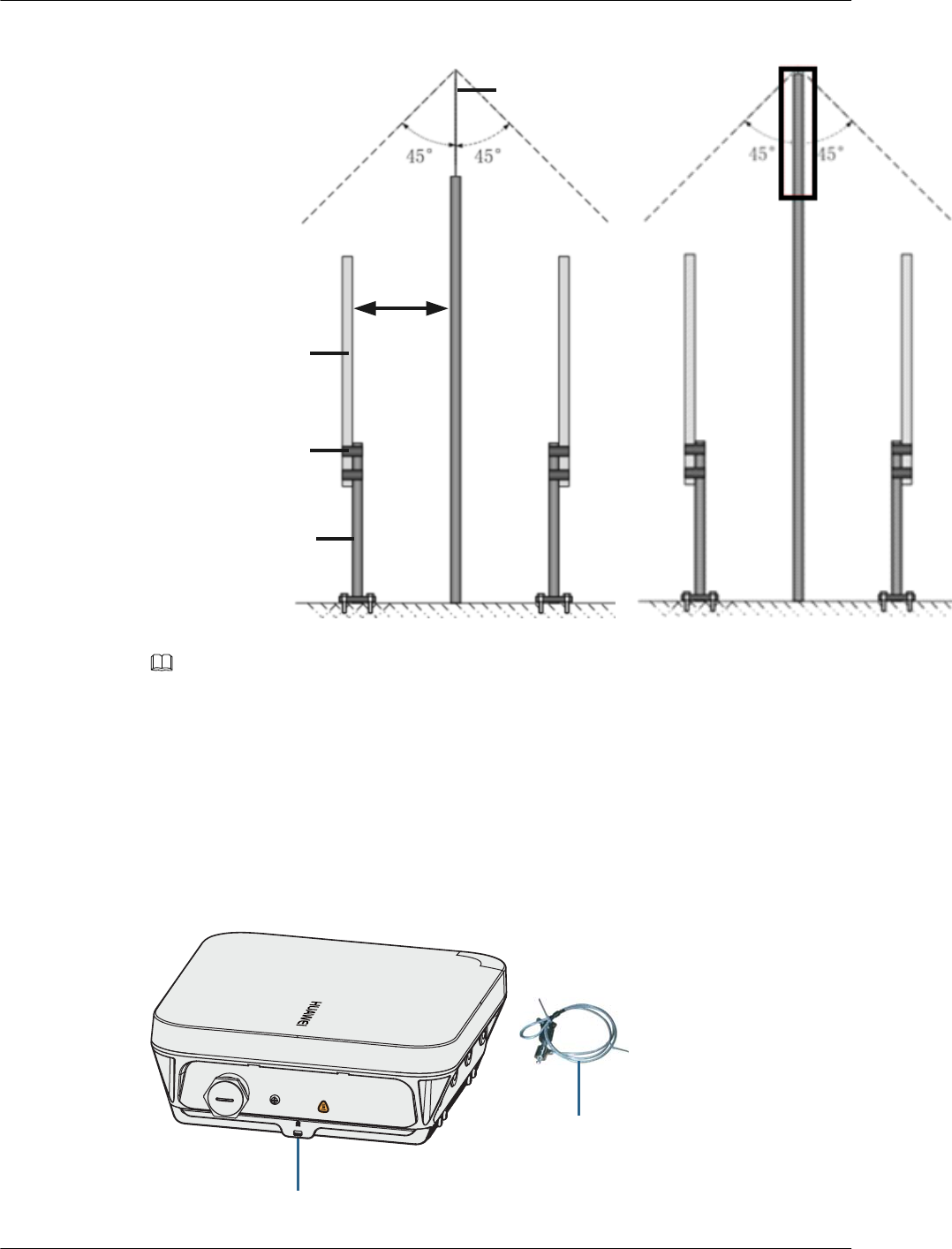
Figure 2-14 Installing an omnidirectional outdoor antenna
Protection
angle
Omnidirectional
antenna
Hose clamp
Antenna pole
Lightning rod
>1.0m
NOTE
If antennas are installed on a metal pole such as a steel pole, you do not need to install a lightening rod, as
shown on the right in Figure 2-14.
2.7 Installing the Security Lock
There is a security slot on the AP. You can lock the AP to an immovable object to prevent the
AP against theft. The detailed procedures are as follows:
1. Fasten the cable of the security lock to an immovable object around.
2. Insert the security lock into the security slot and lock it.
Lock hole
Security lock
Console/RSSI
Default
Huawei AP8030DN & AP8130DN
Hardware Installation and Maintenance Guide 2 AP Installation
Issue 03 (2015-05-18) Huawei Proprietary and Confidential
Copyright © Huawei Technologies Co., Ltd.
39
NOTE
You need to purchase the security lock separately.
2.8 Checking the AP After Installation
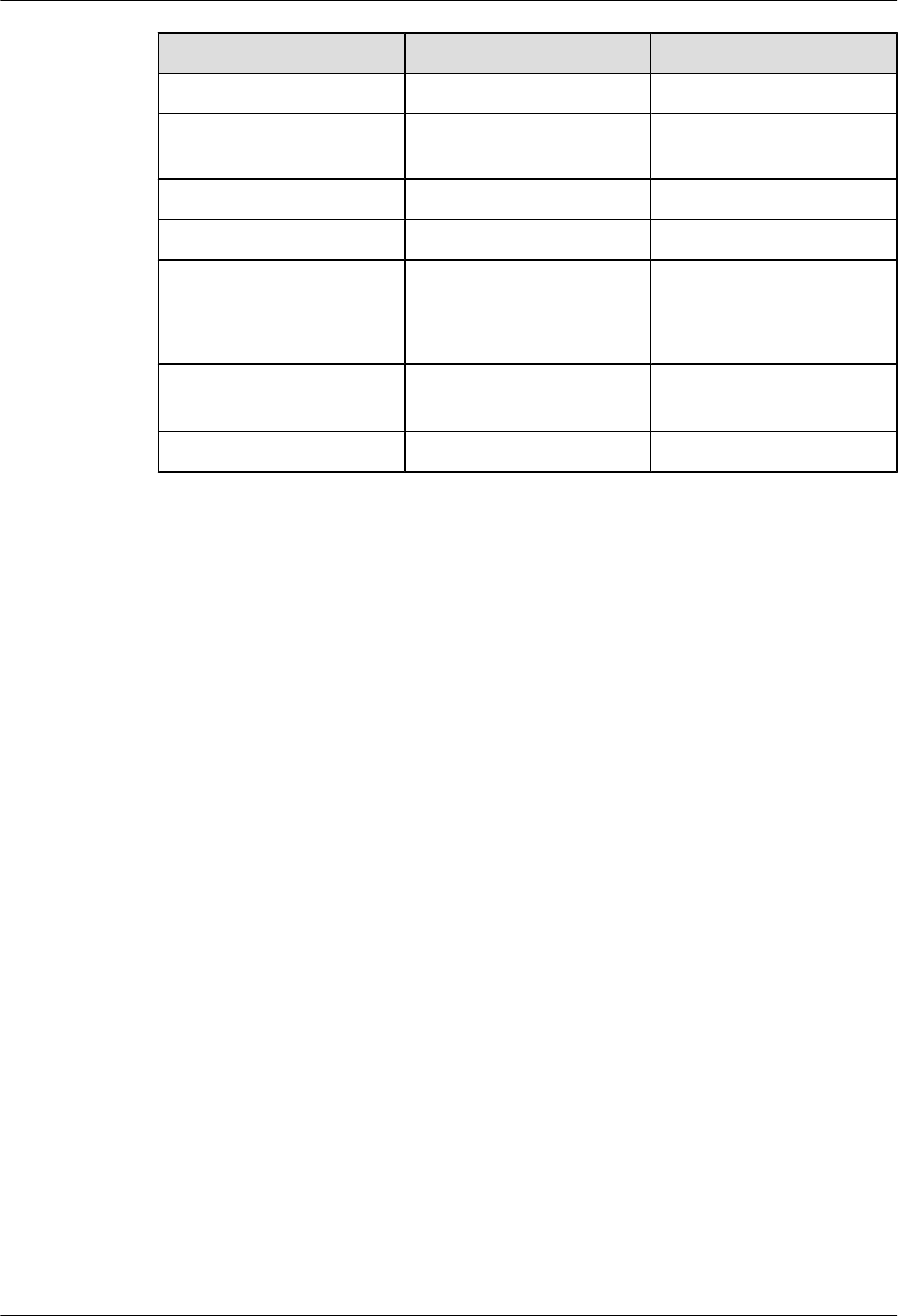
Table 2-4 shows the items to be checked after AP installation is complete.
Table 2-4 AP installation checklist
No. Check Item
1The AP is installed by strictly following the design draft. The installation
position meets space requirements, with maintenance space reserved.
2 The AP is securely installed.
3 Waterproof caps are installed on idle interfaces and securely fastened.
4 The power cables and PGND cables are intact and not spliced.
5 Terminals of the power cables and PGND cables are welded or cramped
firmly.
6 All power cables or PGND cables are not short-circuited or reversely
connected and must be intact with no damage.
7 The power cables and ground cables are separated from other cables and
bundled separately.
8 The working ground, protection ground, and surge protection ground share
the same group of ground bars.
9 Connectors of signal cables are complete, intact, and tightly connected.
The signal cables are not damaged or broken.
10 Labels on cables, feeders, or jumpers are clear and correct.
2.9 Powering on the AP
After the AP installation is complete, observe indicators on the AP to determine the system
running status. For details, see 1.2 Indicator Description.
NOTE
Do not frequently power on and off an AP.
Huawei AP8030DN & AP8130DN
Hardware Installation and Maintenance Guide 2 AP Installation
Issue 03 (2015-05-18) Huawei Proprietary and Confidential
Copyright © Huawei Technologies Co., Ltd.
40
3 Logging In to the AP
About This Chapter
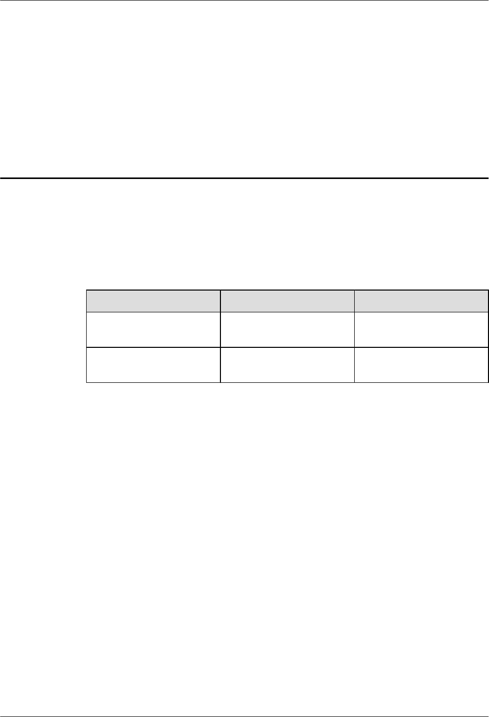
After an AP is powered on, you can log in to the AP using the following method:
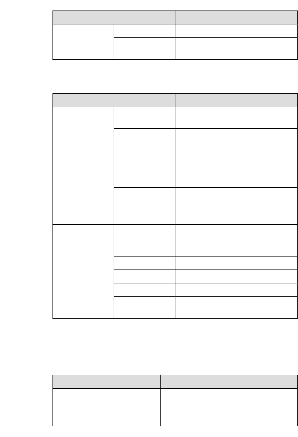
Version Telnet server STelnet server
V200R003C00 and earlier
versions
Enable Enable
V200R005C00 and later
versions
Disable Enable
3.1 Logging In to the AP Through the Console Port
3.2 Logging In to the AP Using STelnet
3.3 Logging In to the AP Using Telnet
3.4 Logging In to the AP Using a Web Client
Huawei AP8030DN & AP8130DN
Hardware Installation and Maintenance Guide 3 Logging In to the AP
Issue 03 (2015-05-18) Huawei Proprietary and Confidential
Copyright © Huawei Technologies Co., Ltd.
41

3.1 Logging In to the AP Through the Console Port
This section describes how to log in to the AP through the console port. After logging in to the
AP, you can configure the AP using commands.
1. Connect a PC to the AP using a console cable. Connect the RJ45 connector to the console
port of the AP and the DB9 connector to the serial port of a PC.
NOTE
If your PC's operating system provides terminal simulation software (like HyperTerminal in
Windows 2000/XP), you do not need to install additional terminal simulation software. If the PC
runs on an operating system without terminal simulation software (like Windows 7), install third-
party terminal simulation software on the PC by referring to user manual or online help.
2. Start the terminal simulation software, create a connection, select a serial port, and set
communication parameters as follows.
lBits per second (B): 9600
lData bits (B): 8
lParity (P): None
lStop bits (S): 1
lFlow control (F): None
3. Press Enter until the command line prompt of the user view, such as <Enterprise AP>, is
displayed. Then, you enter the user configuration interface. You can run commands to
configure the AP. Enter a question mark (?) whenever you need help.
3.2 Logging In to the AP Using STelnet
This section describes how to log in to the AP using STelnet. After logging in to the AP, you
can configure the AP using commands.
Before logging in to the device through STelnet, complete the following tasks:
lStarting the device properly
lPreparing network cables used to connect device interfaces.
lConfiguring the PC's IP address and subnet mask. The IP address must be on the network
segment 169.254.0.0/16 but cannot be 169.254.1.1. 169.254.1.100 is recommended. The
subnet mask is 255.255.0.0.
NOTE
lEnsuring that the IP address 169.254.1.1 and subnet mask 255.255.0.0 have been configured on VLANIF
1 of the device before the delivery, and GE0/0/0 has been added to VLAN 1 by default.
lBefore the device is delivered, the STelnet service has been configured on the device. The STelnet interface
number is 22, and the default user name and password are respectively admin and admin@huawei.com.
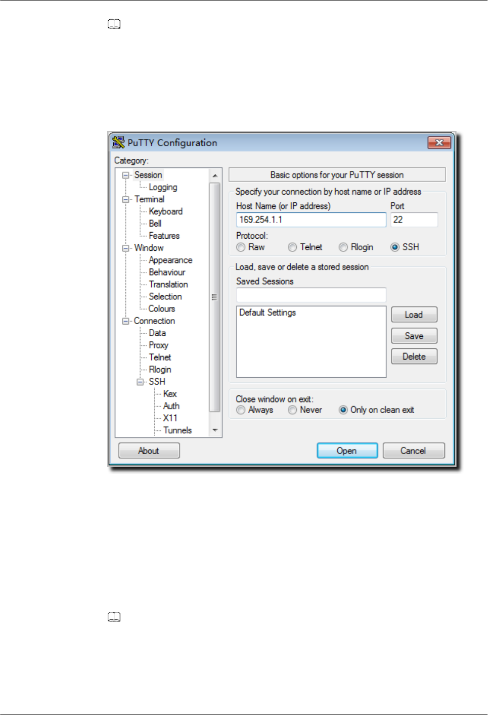
Use the SSH client software to log in to the device through STelnet from a terminal. The
third-party software PuTTY is used as an example here.
1. After the device is powered on, connect the PC's network interface to GE0/0/0 of the device
using network cables.
Huawei AP8030DN & AP8130DN
Hardware Installation and Maintenance Guide 3 Logging In to the AP
Issue 03 (2015-05-18) Huawei Proprietary and Confidential
Copyright © Huawei Technologies Co., Ltd.
42
NOTE
Ping 169.254.1.1 from the PC to check whether the device can be pinged successfully. If the ping
operation fails, check whether the PC's IP address is correct or replace the network cable.
2. Use the PuTTY software to log in to the device, enter the device IP address, and select the
SSH protocol type.
Figure 3-1 PuTTY Configuration page
3. Click Open. Enter the user name and password at the prompt, and press Enter. You have
logged in to the device. (The following information is only for reference.)
login as: admin
Sent username "admin"
admin@169.254.1.1's password:
<Huawei>
NOTE
It is recommended that you change the initial user name and password after login.
3.3 Logging In to the AP Using Telnet
Huawei AP8030DN & AP8130DN
Hardware Installation and Maintenance Guide 3 Logging In to the AP
Issue 03 (2015-05-18) Huawei Proprietary and Confidential
Copyright © Huawei Technologies Co., Ltd.
43

This section describes how to log in to the AP using Telnet. After logging in to the AP, you can
configure the AP using commands.
NOTE
The Telnet protocol poses a security risk, and therefore the STelnet V2 protocol is recommended.
1. Connect a PC to the ETH/PoE interface of the AP using a network cable.
2. Configure a static IP address for the PC. The IP address must be in the same network
segment as the AP's IP address. After completing the configuration, ping the AP's IP address
from the PC. If the ping operation succeeds, the connection is set up successfully. If the
ping operation fails, check whether the network cable is faulty.
NOTE
lThe IP address 169.254.1.1 and subnet mask 255.255.0.0 have been configured on VLANIF 1 of the
AP before the delivery, and GE0/0/1 has been added to VLAN 1 by default.
lIf the AP working in Fit AP mode is online on the AC, the DHCP server automatically assigns an IP
address to the AP. You can remotely log in to the AC on a local terminal and run the following
command to check the AP's IP address:
lFor V200R005C30 and earlier versions: display ap-run-info id ap-id
lFor V200R006C00: display ap run-info ap-name ap-name
3. Enter the command line interface on the PC. For example, in Windows XP, choose Start
> Run and enter cmd in the displayed dialog box.
4. Use Telnet to log in to the AP.
5. Enter the default user name and password. The default user name is admin, and the default
password is admin@huawei.com. If the user view is displayed, you have logged in
successfully. You are advised to change the user name and password on your first login.
NOTE
You can run the quit command to exit from the Telnet window. When the system fails to exit from the
Telnet window:
lIf you logged in to the AP from an AC or a switch, press Ctrl+T to return to the AC or switch view.
This operation does not affect AP services.
lIf you logged in to the AP from a PC, directly close the Telnet window. This operation does not affect
AP services.
3.4 Logging In to the AP Using a Web Client
Pre-configuration Tasks
Before configuring users to log in to the AP using HTTP, complete the following task:
Configure reachable routes between the terminal and the AP.
Huawei AP8030DN & AP8130DN
Hardware Installation and Maintenance Guide 3 Logging In to the AP
Issue 03 (2015-05-18) Huawei Proprietary and Confidential
Copyright © Huawei Technologies Co., Ltd.
44

NOTE
lThe web management system is enabled on the AP before delivery. The default IP address of the web
management system is 169.254.1.1 and the mask is 255.255.0.0. The web management system provides
a default user account, with the user name admin and password admin@huawei.com. You are advised
to change the user name and password on your first login. Assign your PC an IP address on the same
network segment as the default IP address of the web management system, and connect the PC to the
GE interface. Start the web browser on the PC and visit http://169.254.1.1 to log in to the web
management system.
lYou can only log in to the FAT AP using the web platform.
Procedure
Step 1 Open a web browser on a PC, and enter the management address in the format of http://
169.254.1.1 in the address bar. Ensure that the PC and AC can communicate with each other.
Then press Enter. Set the language, user name, and password. The HTTPS login URL is
displayed in the address box indicating that the system has gone to the HTTPS login page.
NOTE
You can also enter https://IP address in the address box to log in to the AP using HTTPS. HTTPS ensures
security of login information during login and security of data exchanged during subsequent operations.
Step 2 Click Login or press Enter. The web system home page is displayed. You can manage and
maintain the equipment. For details, see the Huawei Wireless Access Points Web-based
Configuration.
----End
Huawei AP8030DN & AP8130DN
Hardware Installation and Maintenance Guide 3 Logging In to the AP
Issue 03 (2015-05-18) Huawei Proprietary and Confidential
Copyright © Huawei Technologies Co., Ltd.
45

4 Hardware Failures
About This Chapter
This section describes common methods for troubleshooting typical hardware faults.
4.1 An device Fails to Be Powered On
4.2 An Optical Interface Cannot Turn Up
Huawei AP8030DN & AP8130DN
Hardware Installation and Maintenance Guide 4 Hardware Failures
Issue 03 (2015-05-18) Huawei Proprietary and Confidential
Copyright © Huawei Technologies Co., Ltd.
46

4.1 An device Fails to Be Powered On
Fault Description
The SYS indicator of a device is off.
Possible Causes
lThe power sourcing equipment does not support the PoE function or is faulty.
lThe power sourcing equipment is incorrectly configured (the PoE function is disabled or
the power-off time range is improperly set).
lThe line is faulty (the network cable or distribution frame is damaged).
lThe AP is faulty.
Troubleshooting Procedure
1. Check whether the power sourcing equipment supports PoE or is faulty.
2. Check whether the configuration on the power sourcing equipment causes PoE power
supply errors, such as the PoE function is disabled or the power-off time range is incorrectly
set.
3. Check whether the network cable or distribution frame is faulty.
4. If the device still cannot be powered on, the device itself is faulty. Contact Huawei technical
support engineers or Huawei agent and ask them to replace the device.
4.2 An Optical Interface Cannot Turn Up
Fault Description
After an optical interface is connected to a remote device through an optical fiber, its LINK
indicator is off.
Possible Causes
lThe optical fiber is faulty.
lThe optical module on the optical interface cannot meet the requirements.
Troubleshooting Procedure
1. Replace the optical fiber and optical module and check whether the optical interface can
turn Up. Ensure that the optical module meets the following requirements.
2. Determine optical module attributes.
lThe optical module has passed Huawei certification.
lThe transmission speed of the optical module is the same as the interface speed.
lThe wavelength of the optical module is the same as that of the remote optical module.
lThe transmission distance of the optical module is suitable for the actual distance
between the two devices.
Huawei AP8030DN & AP8130DN
Hardware Installation and Maintenance Guide 4 Hardware Failures
Issue 03 (2015-05-18) Huawei Proprietary and Confidential
Copyright © Huawei Technologies Co., Ltd.
47

NOTE
lThe transmission distance of an optical module is 10 km, 15 km, 20 km, 40 km, or 80 km.
The optical modules with a longer transmission distance have a higher transmit power. If an
optical module with a long transmission distance is used for short-distance transmission, the
optical interface cannot turn Up because the transmit power is too high. The high transmit
power may even burn the receiver of the remote optical module. To reduce the transmit power
in this situation, use an optical attenuator between the optical module and optical fiber.
lOptical modules with different speeds are available, for example, 155 Mbit/s, 622 Mbit/s,
and 1.25 Gbit/s. It is recommended that you use an optical module with the same speed as
the optical interface to ensure efficient optical transmission.
3. If the interface remains Down, contact Huawei technical support.
Huawei AP8030DN & AP8130DN
Hardware Installation and Maintenance Guide 4 Hardware Failures
Issue 03 (2015-05-18) Huawei Proprietary and Confidential
Copyright © Huawei Technologies Co., Ltd.
48

5 Appendix
About This Chapter
5.1 On-site Cable Assembly and Installation
5.2 Environmental Requirements for Device Operation
5.3 Equipment Grounding Specifications
5.4 Engineering Labels for Cables
5.5 Guide to Using Optical Modules
5.6 Fault Tag
Huawei AP8030DN & AP8130DN
Hardware Installation and Maintenance Guide 5 Appendix
Issue 03 (2015-05-18) Huawei Proprietary and Confidential
Copyright © Huawei Technologies Co., Ltd.
49

5.1 On-site Cable Assembly and Installation
5.1.1 Cable Assembly Precautions
Checking the Appearance of Cables
lIf the cable jacket or insulation is visibly dirty, clean it before assembly.
lIf the jacket or insulation of a cable has visible damage, irreparable scuffing, or other
defects, do not use the cable.
lIf the shield layer of a cable is damaged, do not use the cable.
lIf the cable jacket or insulation cracks after the cable is bent or twisted, discard this cable
and check whether other cables have the same problem. If other cables have the same
problem, replace these cables.
Checking the Appearance of Connectors
lDo not use connectors with visible defects, damage, rust or scuffing.
lDo not use connectors if their shells or pins have exposed part or uneven plating, or their
pins are lost, broken, or bent.
lDo not use connectors that have dirt on their pins or in their jacks or if there are conductors
between pins or between pins and the shell.
Precautions for Assembly
lUse dedicated tools or tools delivered by Huawei and follow the methods given here during
assembly.
lHold terminals of cables instead of pulling the cables when installing or removing cable
components.
lTake the following precautions when cutting or stripping cables:
–Make cables slightly longer than necessary.
–Coil cables longer than 2 m (6.56 ft) after cutting. Bind and fasten the coils using
bundling ropes. The inner diameters of the coils should be larger than 20 times the outer
diameters of the cables.
–When stripping the jackets of cables, avoid damaging the shield layers (braid or
aluminum foil), insulation, core conductors, and other jackets that do not need to be
stripped.
–After assembling cables, cut all visible cross sections of jackets to ensure that the cross
sections are arranged neatly.
–Do not touch the core conductors of cables with your hands. Terminate exposed
conductors in a timely way after stripping off insulation so that the surface of the
conductors does not become oxidized.
lTake the following precautions when crimping and connecting cables or connectors:
Huawei AP8030DN & AP8130DN
Hardware Installation and Maintenance Guide 5 Appendix
Issue 03 (2015-05-18) Huawei Proprietary and Confidential
Copyright © Huawei Technologies Co., Ltd.
50
–The terminals and conductors should be connected tightly after they are crimped. They
should not be moved or turned.
–Cut all the exposed copper wires.
–Try to avoid a second crimping of sleeves.
–Keep all the conductors clean and aligned.
NOTE
The connectors, cables, and tools provided by different vendors may be different. The figures in this
document are only for your reference.
5.1.2 Assembling Power Cables
Assembling the OT Terminal and Power Cable
Context
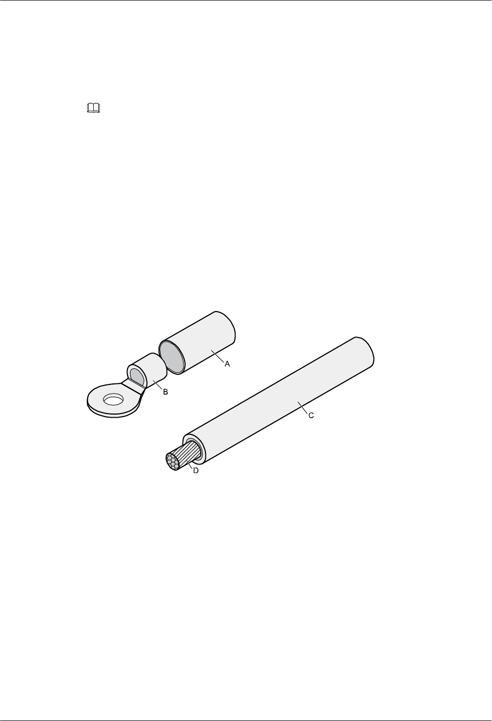
Figure 5-1 shows the components of an OT terminal and a power cable.
Figure 5-1 Components of an OT terminal and a power cable
A Heat-shrinkable tubing B. Bare crimping terminal C. Insulation D. Conductor
Procedure
Step 1 Based on the cross-sectional area of the cable conductor, strip a length of insulation coating C
to expose the conductor D of length L1, as shown in Figure 5-2. The recommended values of
L1 are listed in Table 5-1.
Huawei AP8030DN & AP8130DN
Hardware Installation and Maintenance Guide 5 Appendix
Issue 03 (2015-05-18) Huawei Proprietary and Confidential
Copyright © Huawei Technologies Co., Ltd.
51
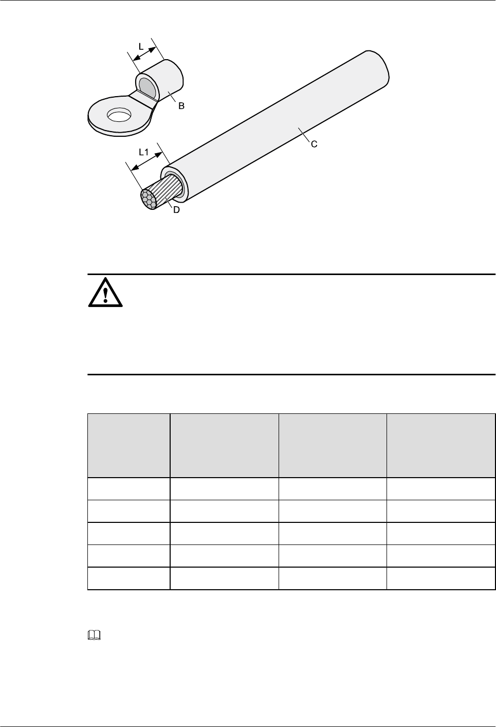
Figure 5-2 Stripping a power cable (OT terminal)
NOTICE
lWhen you strip a power cable, do not damage the conductor of the cable.
lIf the bare crimping terminal is not provided by Huawei, the value of L1 is 1 mm (0.04 in.)
to 2 mm (0.08 in.) greater than the value of L.
Table 5-1 Mapping between the cross-sectional area of the conductor and the value of L1
Cross-
Sectional Area
of Conductor
(mm2(in.2))
Value of L1 (mm
(in.))
Cross-Sectional
Area of Conductor
(mm2(in.2))
Value of L1 (mm
(in.))
1 (0.002) 7 (0.28) 10 (0.015) 11 (0.43)
1.5 (0.002) 7 (0.28) 16 (0.025) 13 (0.51)
2.5 (0.004) 7 (0.28) 25 (0.039) 14 (0.55)
4 (0.006) 8 (0.31) 35 (0.054) 16 (0.63)
6 (0.009) 9 (0.35) 50 (0.077) 16 (0.63)
NOTE
If you are proficient in assembling OT terminals and power cables, you can obtain the value of L1 by
comparing the part to be crimped with the power cable.
Step 2 Put the heat-shrinkable (A) tubing onto the bare crimping terminal, as shown in Figure 5-3.
Huawei AP8030DN & AP8130DN
Hardware Installation and Maintenance Guide 5 Appendix
Issue 03 (2015-05-18) Huawei Proprietary and Confidential
Copyright © Huawei Technologies Co., Ltd.
52
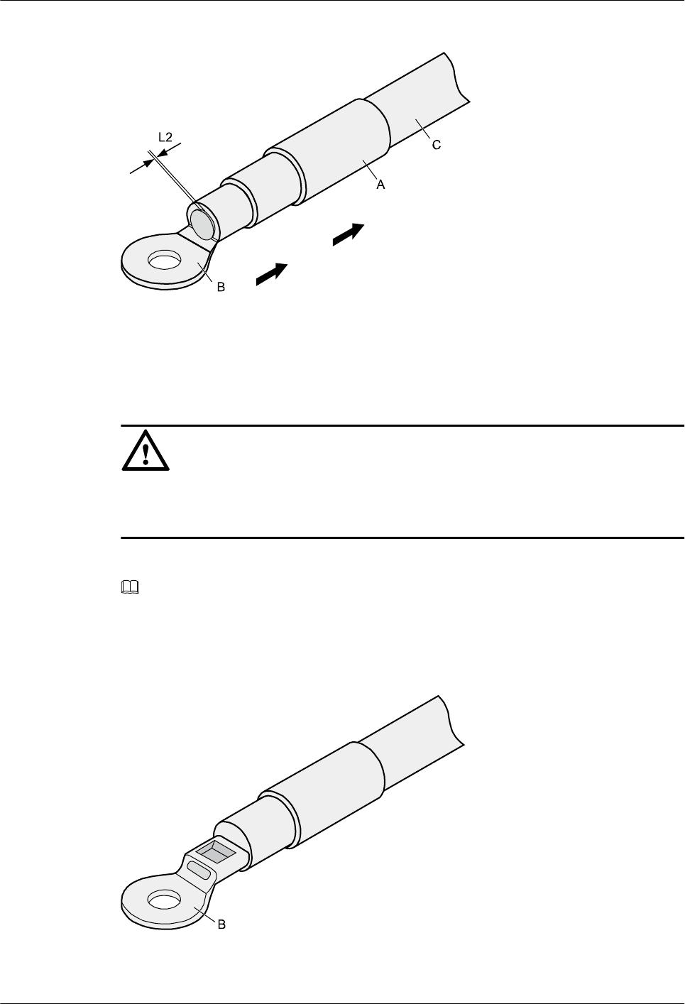
Figure 5-3 Putting the heat shrink tubing onto the bare crimping terminal
Step 3 Put the OT terminal B onto the exposed conductor, and ensure that the OT terminal is in good
contact with the insulation coating C, as shown in Figure 5-3.
NOTICE
After the conductor is fed into the OT terminal, the protruding part of the conductor, or L2 in
Figure 5-3, must not be longer than 2 mm (0.08 in.).
Step 4 Crimp the joint parts of the bare crimping terminal and the conductor, as shown in Figure 5-4.
NOTE
The shapes of crimped parts may vary with the crimping dies.
Figure 5-4 Crimping the joint parts of the bare crimping terminal and the conductor (OT
terminal)
Huawei AP8030DN & AP8130DN
Hardware Installation and Maintenance Guide 5 Appendix
Issue 03 (2015-05-18) Huawei Proprietary and Confidential
Copyright © Huawei Technologies Co., Ltd.
53
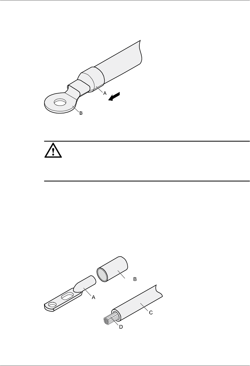
Step 5 Push the heat shrink tubing (A) towards the connector until the tube covers the crimped part,
and then heat the tube by using a heat gun, as shown in Figure 5-5.
Figure 5-5 Heating the heat shrink tubing (OT terminal)
NOTICE
Stop heating the shrink tubing when the connector is securely locked in the shrink tubing. Do
not heat the shrink tubing too long to damage the insulation coating.
----End
Assembling the JG Terminal and Power Cable
Context
Figure 5-6 shows the components of a JG terminal and a power cable.
Figure 5-6 Components of a JG terminal and a power cable
A. JG terminal B. Heat-shrinkable tube C. Insulation layer of a power cable D. Conductor of a power cable
Huawei AP8030DN & AP8130DN
Hardware Installation and Maintenance Guide 5 Appendix
Issue 03 (2015-05-18) Huawei Proprietary and Confidential
Copyright © Huawei Technologies Co., Ltd.
54
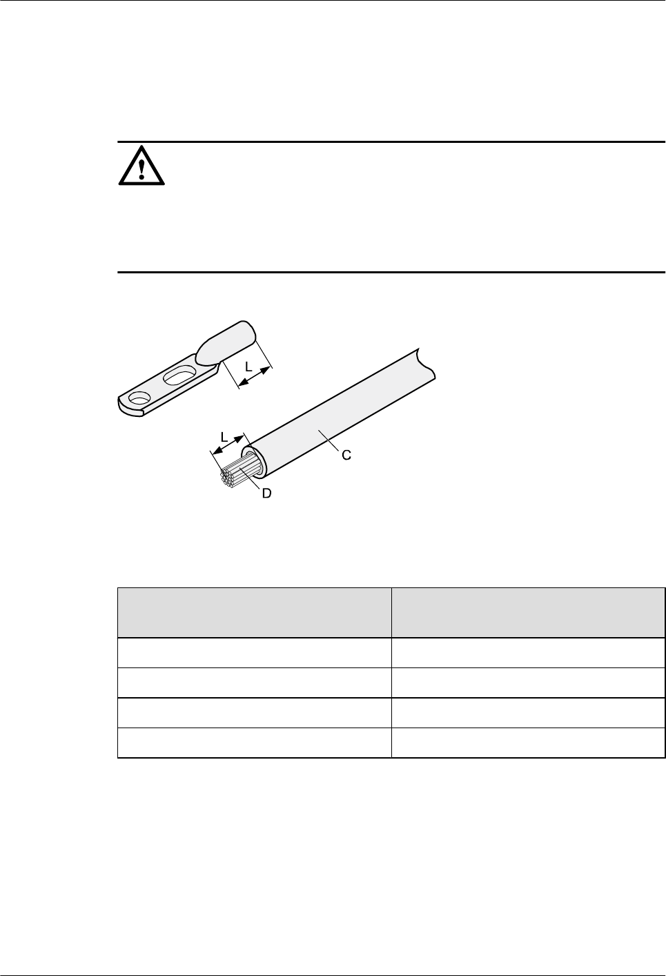
Procedure
Step 1 Based on the cross-sectional area of the cable conductor, strip a part of the cable. The L-long
conductor is exposed, as shown in Figure 5-7. The recommended values of L are listed in Table
5-2.
NOTICE
lWhen you strip a power cable, do not damage the conductor of the cable.
lIf the bare crimping terminal is not provided by Huawei, you can adjust the value of L as
required.
Figure 5-7 Stripping a power cable (JG terminal)
Table 5-2 Mapping between the cross-sectional area of the conductor and the value of L
Cross-Sectional Area of Conductor
(mm2(in.2))
Value of L (mm(in.))
16 (0.025) 13 (0.51)
25 (0.039) 14 (0.55)
35 (0.054) 16 (0.63)
50 (0.077) 16 (0.63)
Step 2 Put the heat shrink tubing onto the bare crimping terminal, as shown in Figure 5-8.
Huawei AP8030DN & AP8130DN
Hardware Installation and Maintenance Guide 5 Appendix
Issue 03 (2015-05-18) Huawei Proprietary and Confidential
Copyright © Huawei Technologies Co., Ltd.
55
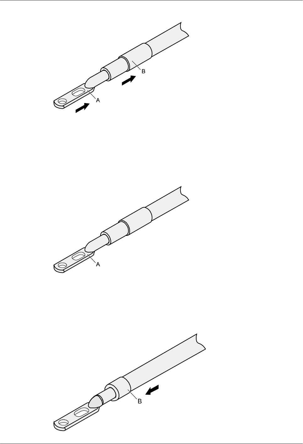
Figure 5-8 Putting the heat shrink tubing onto the bare crimping terminal
Step 3 Put the bare crimping terminal onto the exposed conductor, and ensure that the bare crimping
terminal is in good contact with the insulation of the power cable, as shown in Figure 5-8.
Step 4 Crimp the joint parts of the bare crimping terminal and the conductor, as shown in Figure 5-9.
Figure 5-9 Crimping the joint parts of the bare crimping terminal and the conductor (JG terminal)
Step 5 Push the heat shrink tubing towards the connector until the tube covers the crimped part, and
then heat the tube by using a heat gun, as shown in Figure 5-10.
Figure 5-10 Heating the heat shrink tubing (JG terminal)
Huawei AP8030DN & AP8130DN
Hardware Installation and Maintenance Guide 5 Appendix
Issue 03 (2015-05-18) Huawei Proprietary and Confidential
Copyright © Huawei Technologies Co., Ltd.
56
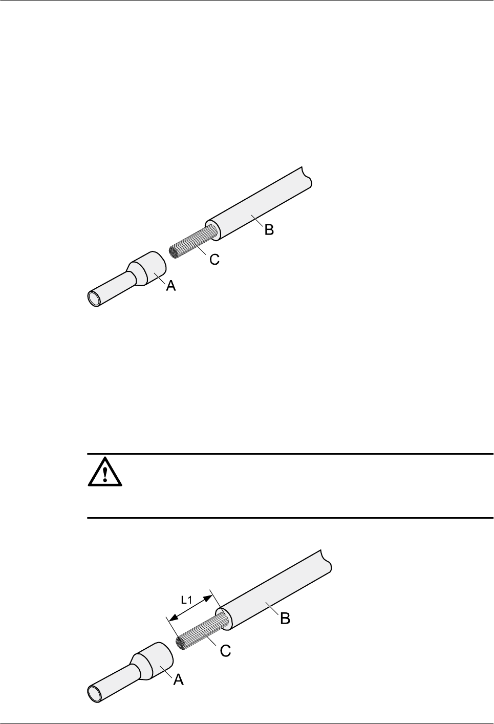
----End
Assembling the Cord End Terminal and the Power Cable
Context
Figure 5-11 shows the components of a cord end terminal and a power cable.
Figure 5-11 Components of a cord end terminal and a power cable
A. Cord end terminal B. Insulation layer of a power cable C. Conductor of a power cable
Procedure
Step 1 Based on the cross-sectional area of the cable conductor, strip a part of the insulation. The L1-
long conductor is exposed, as shown in Figure 5-12. The recommended values of L1 are listed
in Table 5-3.
NOTICE
When you strip a power cable, do not damage the conductor of the cable.
Figure 5-12 Stripping a power cable (cord end terminal)
Huawei AP8030DN & AP8130DN
Hardware Installation and Maintenance Guide 5 Appendix
Issue 03 (2015-05-18) Huawei Proprietary and Confidential
Copyright © Huawei Technologies Co., Ltd.
57
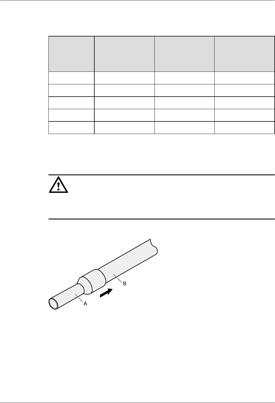
Table 5-3 Mapping between the cross-sectional area of the conductor and the value of L1
Cross-
Sectional Area
of Conductor
(mm2(in.2))
Value of L1 (mm
(in.))
Cross-Sectional
Area of Conductor
(mm2(in.2))
Value of L1 (mm
(in.))
1 (0.002) 8 (0.31) 10 (0.015) 15 (0.59)
1.5 (0.002) 10 (0.39) 16 (0.025) 15 (0.59)
2.5 (0.004) 10 (0.39) 25 (0.039) 18 (0.71)
4 (0.006) 12 (0.47) 35 (0.054) 19 (0.75)
6 (0.009) 14 (0.55) 50 (0.077) 26 (1.02)
Step 2 Putting the cord end terminal onto the conductor, and ensure that the conductor is aligned with
the edge of the cord end terminal, as shown in Figure 5-13.
NOTICE
After the conductor is fed into the cord end terminal, the protruding part of the conductor must
not be longer than 1 mm (0.04 in.).
Figure 5-13 Put the cord end terminal onto the conductor
Step 3 Crimp the joint parts of the cord end terminal and the conductor, as shown in Figure 5-14.
Huawei AP8030DN & AP8130DN
Hardware Installation and Maintenance Guide 5 Appendix
Issue 03 (2015-05-18) Huawei Proprietary and Confidential
Copyright © Huawei Technologies Co., Ltd.
58
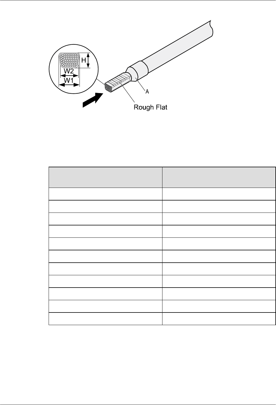
Figure 5-14 Crimping the cord end terminal and the conductor
Step 4 Check the maximum width of the tubular crimped terminal. The maximum width of a tubular
crimped terminal is listed in Table 5-4.
Table 5-4 Maximum width of a tubular crimped terminal
Cross-Sectional Area of Tubular
Terminal (mm2(in.2))
Maximum Width of Crimped Terminal
W1 (mm(in.))
0.25 (0.0004) 1 (0.04)
0.5 (0.0008) 1 (0.04)
1.0 (0.0015) 1.5 (0.06)
1.5 (0.0023) 1.5 (0.06)
2.5 (0.0039) 2.4 (0.09)
4 (0.006) 3.1 (0.12)
6 (0.009) 4 (0.16)
10 (0.015) 5.3 (0.21)
16 (0.025) 6 (0.24)
25 (0.039) 8.7 (0.34)
35 (0.054) 10 (0.39)
----End
5.1.3 Assembling Ethernet Cables
Assembling the Shielded RJ45 Connector and Ethernet Cable
Huawei AP8030DN & AP8130DN
Hardware Installation and Maintenance Guide 5 Appendix
Issue 03 (2015-05-18) Huawei Proprietary and Confidential
Copyright © Huawei Technologies Co., Ltd.
59
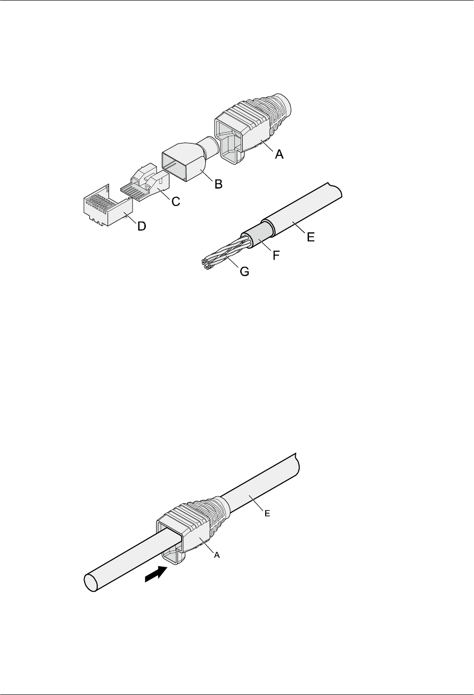
Context
Figure 5-15 shows the components of an RJ45 connector and a shielded Ethernet cable.
Figure 5-15 Shielded RJ45 connector and cable
A. Jacket of connector B. Metal shell of connector C. Wire holder of connector D. Plug of connector
E. Jacket of Ethernet cable F. Shield layer of Ethernet cable G. Twisted-pair wires -
Procedure
Step 1 Fit the jacket of the connector onto the Ethernet cable, as shown in Figure 5-16.
Figure 5-16 Fit the jacket of the connector onto the Ethernet cable
Step 2 Remove a 30 mm (1.18 in.) long section of the jacket, cut off the nylon twine inside the jacket,
and cut a no more than 5 mm (0.20 in.) cleft in the jacket, as shown in Figure 5-17.
Huawei AP8030DN & AP8130DN
Hardware Installation and Maintenance Guide 5 Appendix
Issue 03 (2015-05-18) Huawei Proprietary and Confidential
Copyright © Huawei Technologies Co., Ltd.
60
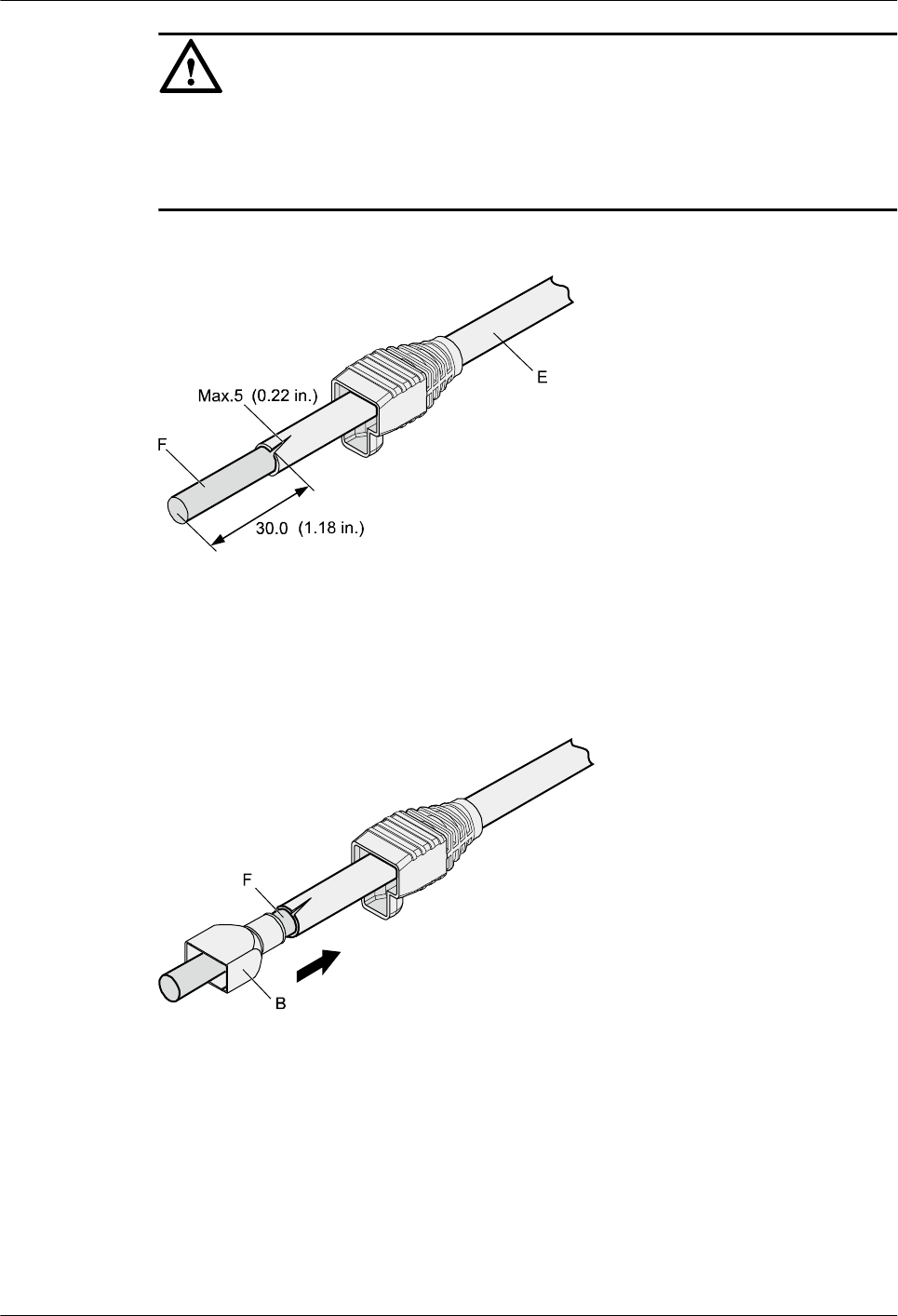
NOTICE
lWhen you remove a section of the jacket, do not damage the shield layer of the twisted-pair
cable.
lWhen you remove the shield layer, do not damage the insulation of the twisted-pair cable.
Figure 5-17 Removing the jacket of a twisted-pair cable (unit: mm (in.))
Step 3 Fit the metal shell onto the twisted-pair cable. The shield layer is covered by the metal shell, as
shown in Figure 5-18.
Figure 5-18 Fitting the metal shell onto the twisted-pair cable
Step 4 Fit the metal shell onto the twisted-pair cable until the shield layer is covered completely. Along
the edge of the metal shell, cut off the aluminum foil shield layer and ensure that there is no
surplus copper wire. The exposed twisted-pair cable is about 20 mm (0.79 in.) long, as shown
in Figure 5-19.
Huawei AP8030DN & AP8130DN
Hardware Installation and Maintenance Guide 5 Appendix
Issue 03 (2015-05-18) Huawei Proprietary and Confidential
Copyright © Huawei Technologies Co., Ltd.
61
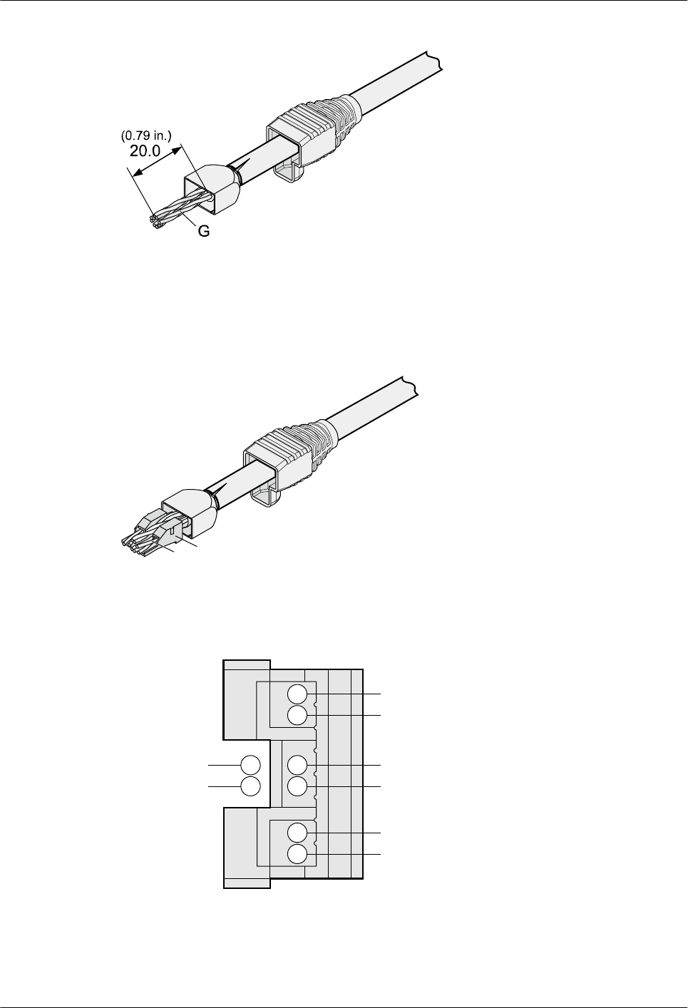
Figure 5-19 Removing the shield layer of a twisted-pair cable (unit: mm (in.))
Step 5 Based on the colors, lead the four pairs of twisted-pair wires through the wire holder, as shown
in Figure 5-20 and Figure 5-21.
Figure 5-20 Leading wires through the wire holder
C
G
Figure 5-21 Cable locations in a wire holder
White-Green
Green
White-Orange
Orange
Blue
White-Blue
White-Brown
Brown
Step 6 Align the four pairs of cables in the holder, as shown in Figure 5-22. The connections between
the wires and the pins are shown in Figure 5-23 and listed in Table 5-5.
Huawei AP8030DN & AP8130DN
Hardware Installation and Maintenance Guide 5 Appendix
Issue 03 (2015-05-18) Huawei Proprietary and Confidential
Copyright © Huawei Technologies Co., Ltd.
62
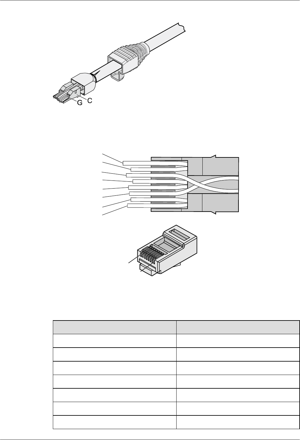
Figure 5-22 Four pairs of cables on a wire holder
Figure 5-23 Connections between wires and pins
Brown
White-Brown
Green
White-Blue
Blue
White-Green
Orange
White-Orange
Pin 8
Pin 1
Table 5-5 Connections between wires and pins (using a straight-through cable as an example)
Matching Pins of Wires Wire Color
1White-Orange
2 Orange
3 White-Green
4 Blue
5 White-Blue
6 Green
7 White-Brown
Huawei AP8030DN & AP8130DN
Hardware Installation and Maintenance Guide 5 Appendix
Issue 03 (2015-05-18) Huawei Proprietary and Confidential
Copyright © Huawei Technologies Co., Ltd.
63
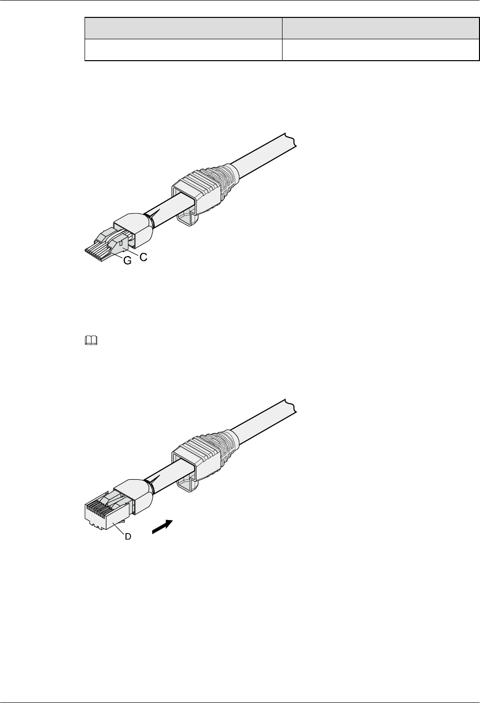
Matching Pins of Wires Wire Color
8Brown
Step 7 Cut off the surplus cables along the lower edge of the wire holder, as shown in Figure 5-24.
Figure 5-24 Cutting off surplus cables
Step 8 Put the connector body onto the wire holder and turn the metal shell by 90°, as shown in Figure
5-25.
NOTE
Ensure that the wire holder is in good contact with the connector body.
Figure 5-25 Put the connector body onto the wire holder
Step 9 Push the metal shell towards the connector body until the wire holder and the connector body
are engaged completely. Crimp the connector, as shown in Figure 5-26.
Huawei AP8030DN & AP8130DN
Hardware Installation and Maintenance Guide 5 Appendix
Issue 03 (2015-05-18) Huawei Proprietary and Confidential
Copyright © Huawei Technologies Co., Ltd.
64
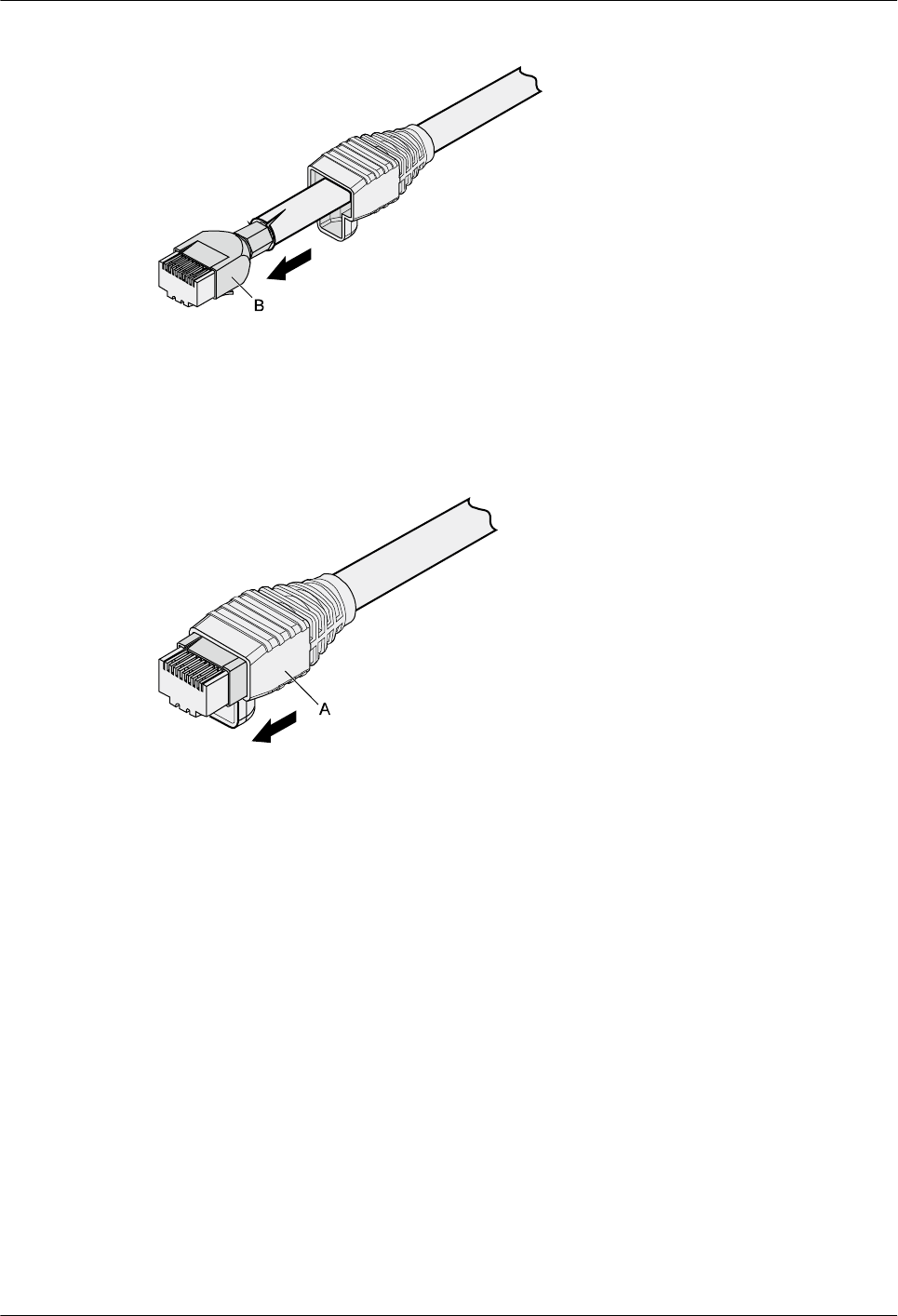
Figure 5-26 Crimping the connector
Step 10 Push the jacket towards the metal shell until the metal shell is covered. This completes the
assembly of one end of the cable, as shown in Figure 5-27.
Figure 5-27 Pushing the metal shell
Step 11 To complete the assembly of the other end, repeat Step 1 through Step 10.
----End
Assembling an Unshielded RJ45 Connector and Ethernet Cable
Context
Figure 5-28 shows the components of an unshielded RJ45 connector and cable.
Huawei AP8030DN & AP8130DN
Hardware Installation and Maintenance Guide 5 Appendix
Issue 03 (2015-05-18) Huawei Proprietary and Confidential
Copyright © Huawei Technologies Co., Ltd.
65
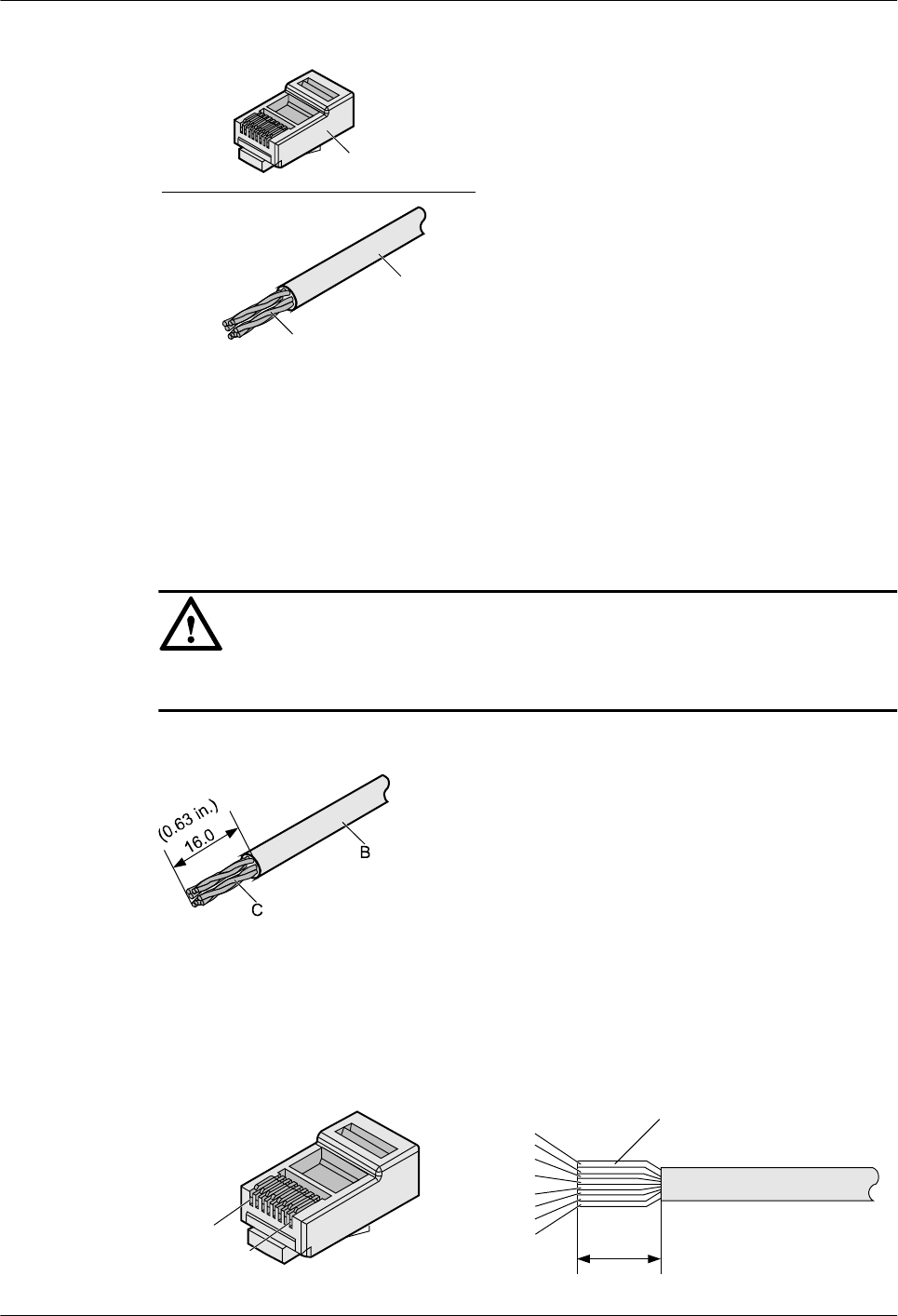
Figure 5-28 Components of an unshielded RJ45 connector and cable
A
B
C
A. Plug of connector B. Jacket C. Twisted-pair wires
Procedure
Step 1 Remove a 16-mm (0.63 in.) long section of the jacket, as shown in Figure 5-29.
NOTICE
When you remove the shield layer, do not damage the insulation of the twisted-pair cable.
Figure 5-29 Removing the jacket of a twisted-pair cable (unit: mm (in.))
Step 2 Align the four pairs of wires and cut the ends neatly, as shown in Figure 5-30. The connections
between the wires and the pins are listed in Table 5-6.
Figure 5-30 Connections between wires and pins (unit: mm (in.))
C
16
White-Orange
White-Green
Orange
Blue
White-Blue
Green
White-Brown
Brown
Pin 8
Pin 1
Huawei AP8030DN & AP8130DN
Hardware Installation and Maintenance Guide 5 Appendix
Issue 03 (2015-05-18) Huawei Proprietary and Confidential
Copyright © Huawei Technologies Co., Ltd.
66
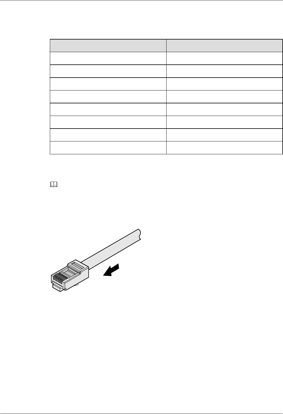
Table 5-6 Connections between wires and pins (using a straight-through cable as an example)
Matching Pins of Wires Wire Color
1White-Orange
2 Orange
3 White-Green
4 Blue
5 White-Blue
6 Green
7 White-Brown
8 Brown
Step 3 Feed the cable into the plug, and crimp the connector, as shown in Figure 5-31.
NOTE
When inserting the cable, check from the side or bore of the plug to ensure that the cable is completely
seated in the plug.
Figure 5-31 Crimping the connector
Step 4 To complete the assembly of the other end, repeat Step 1 through Step 3.
----End
Checking the Appearance of Contact Strips
Context
lTo ensure proper contact between the crimped wires and the wire conductors, the heights
and sizes of the contact strips must be standard and the same.
Huawei AP8030DN & AP8130DN
Hardware Installation and Maintenance Guide 5 Appendix
Issue 03 (2015-05-18) Huawei Proprietary and Confidential
Copyright © Huawei Technologies Co., Ltd.
67
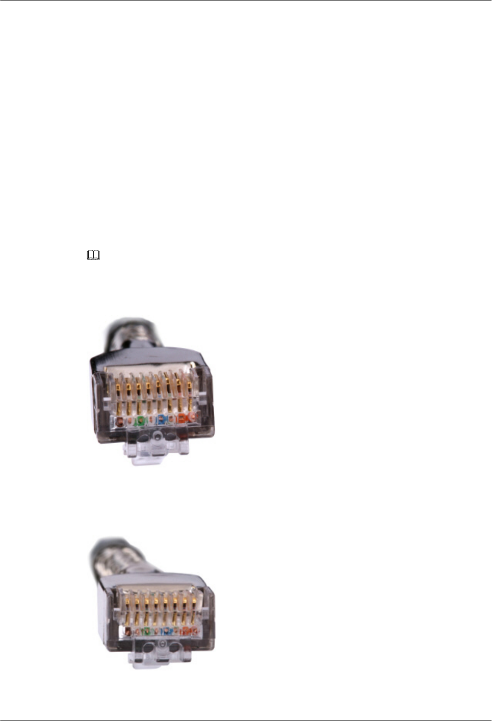
lThe contact strips must be parallel to each other, with an offset less than ± 5°. The top
margin of a strip must be parallel to the axis of the connector, with an offset less than ±
10°.
lTo ensure conduction, the surface of the contact strips must be clean.
lThe contact strips must be in good contact with the RJ45 socket. The plastic separators
must remain intact and be aligned.
lThe contact strip blade must extend beyond the ends of the wires. The ends of the wires
must be in contact with the edge of the RJ45. The distance between them must be less than
0.5 mm (0.02 in.).
Procedure
Step 1 Hold the crimped connector, with the front side facing you, and check whether the contact strips
are of the same height. The height should be 6.02 ± 0.13 mm (0.237 ± 0.005). If a measuring
tool is not available, you can compare the connector with a standard connector. Figure 5-32
shows an unqualified piece, and Figure 5-33 shows a qualified piece.
NOTE
All unqualified pieces must be crimped again.
Figure 5-32 Contact strips of different heights
Figure 5-33 Contact strips of the same height
Huawei AP8030DN & AP8130DN
Hardware Installation and Maintenance Guide 5 Appendix
Issue 03 (2015-05-18) Huawei Proprietary and Confidential
Copyright © Huawei Technologies Co., Ltd.
68
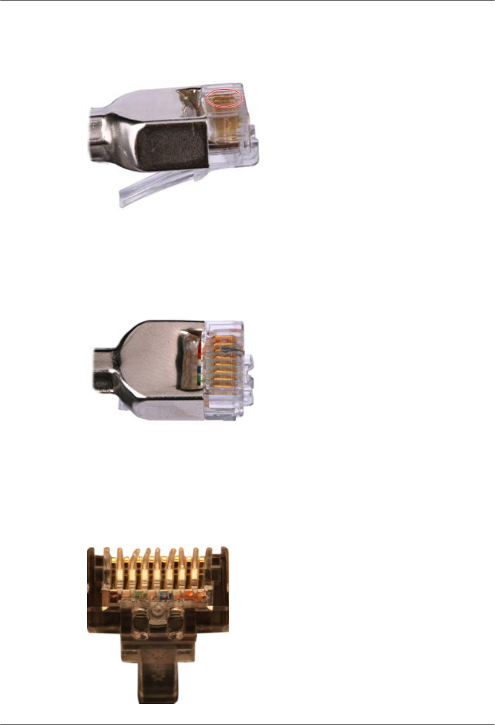
Step 2 Hold an RJ45 connector and turn it 45°. Observe the top edges of the metal contact strips. Figure
5-34 shows an unqualified piece.
Figure 5-34 Unparallel contact strips of different heights
Step 3 Check whether the contact strips are clean. If they are not clean and the dirt cannot be removed,
replace it with a new RJ45 connector. Figure 5-35 shows an unqualified piece.
Figure 5-35 Dirt on a contract strip
Step 4 Check whether the contact strips and the plastic separators are well aligned and intact. If a
separator is skew and cannot be fixed, replace it with a new RJ45 connector. Figure 5-36 shows
an unqualified piece.
Figure 5-36 Skew plastic separators
Huawei AP8030DN & AP8130DN
Hardware Installation and Maintenance Guide 5 Appendix
Issue 03 (2015-05-18) Huawei Proprietary and Confidential
Copyright © Huawei Technologies Co., Ltd.
69
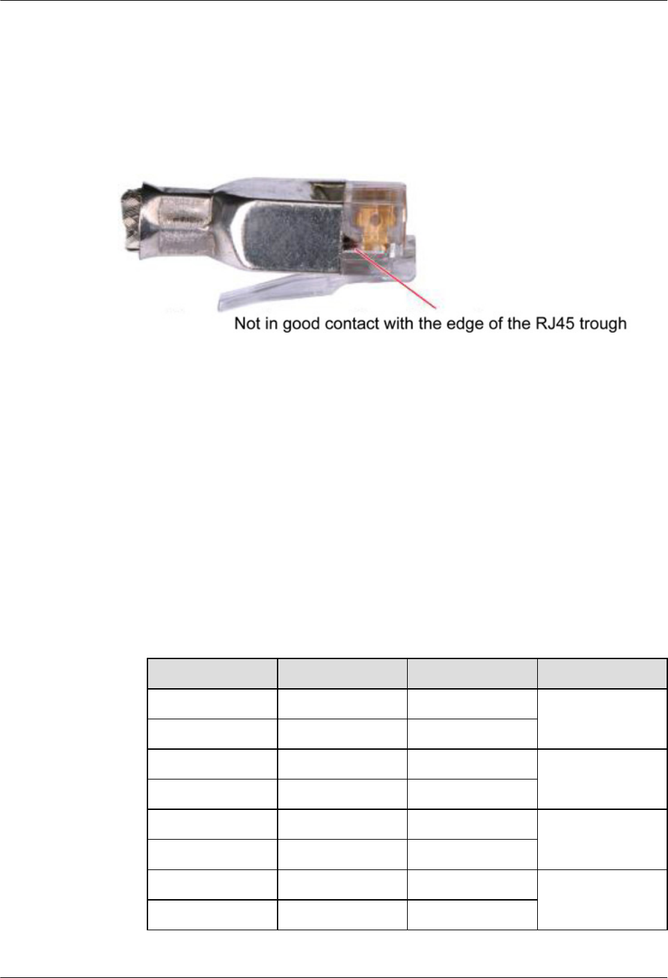
Step 5 Hold the connector with the side facing towards you, and check whether you can see the cross-
sections of the wires. Ensure that the ends of the wires are in good contact with the edge of the
RJ45, and that the contact strip blade extends beyond the ends of the wires and is crimped with
the wires. If not, replace the connector. Figure 5-37 shows an unqualified piece.
Figure 5-37 Wires not in good contact with the edge of the RJ45
----End
Testing the Connection of Assembled Cables
Context
Huawei provides two types of Ethernet cables: straight-through cables and crossover cables.
lStraight-through cables are connected in a one-to-one manner. They are used to connect
terminals such as a computer or switch to network devices. Table 5-7 lists the connections
of core wires in a straight-through cable.
Table 5-7 Connections of core wires in a straight-through cable
RJ45 Connector 1 RJ45 Connector 2 Core Wire Color Twisted or Not
2 2 Orange Twisted
1 1 Orange-White
6 6 Green Twisted
3 3 Green-White
4 4 Blue Twisted
5 5 Blue-White
8 8 Brown Twisted
7 7 Brown-White
Huawei AP8030DN & AP8130DN
Hardware Installation and Maintenance Guide 5 Appendix
Issue 03 (2015-05-18) Huawei Proprietary and Confidential
Copyright © Huawei Technologies Co., Ltd.
70
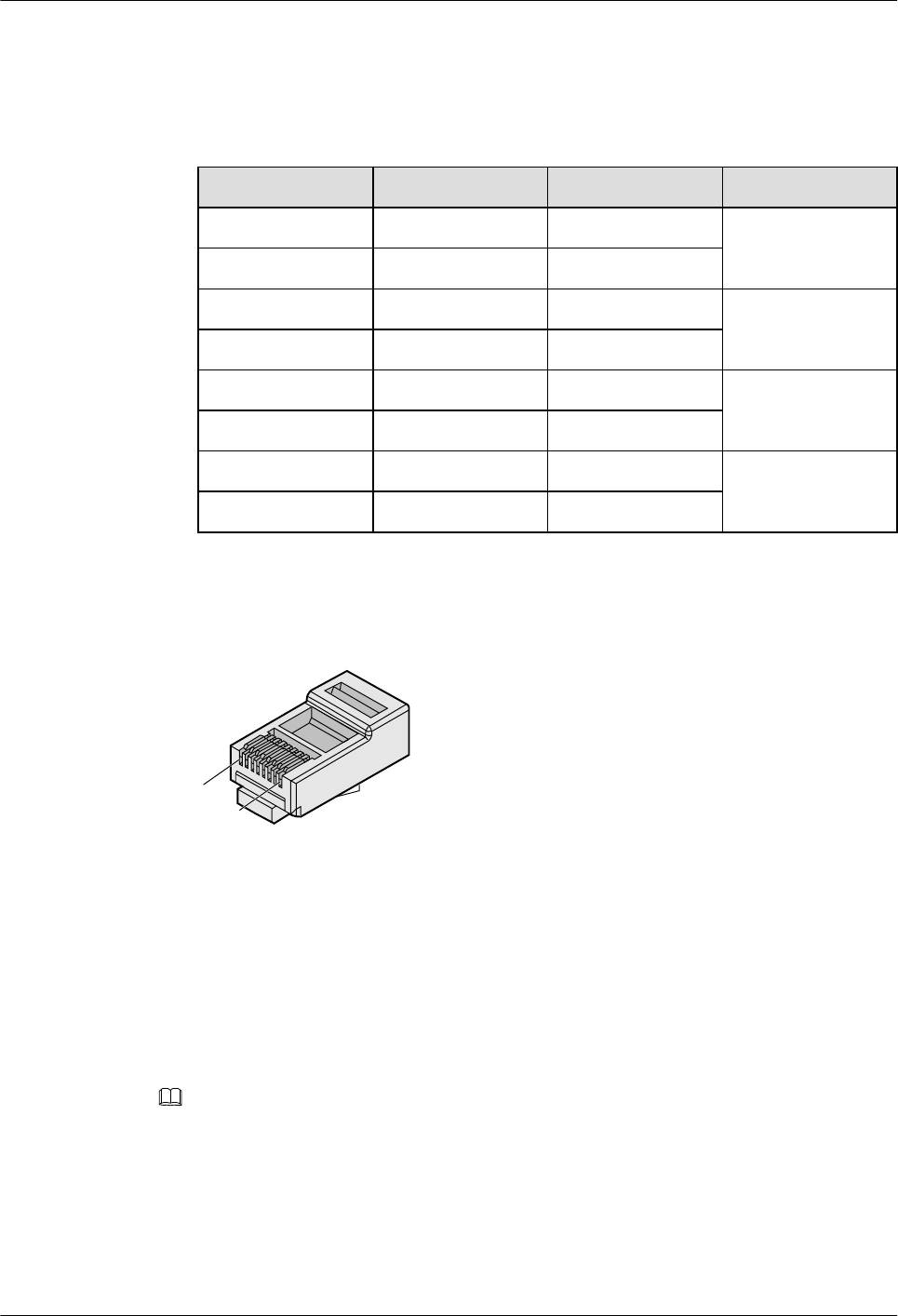
lCrossover cables are connected in a crossover manner. They are used to connect terminals
such as two computers or switches. Table 5-8 lists the connections of core wires in a
crossover cable.
Table 5-8 Connections of core wires in a straight crossover cable
RJ45 Connector 1 RJ45 Connector 2 Core Wire Color Twisted or Not
6 2 Orange Twisted
3 1 Orange-White
2 6 Green Twisted
1 3 Green-White
4 4 Blue Twisted
5 5 Blue-White
8 8 Brown Twisted
7 7 Brown-White
Figure 5-38 shows the pins of an RJ45 connector.
Figure 5-38 Pins of an RJ45 connector
Pin8
Pin1
Procedure
Step 1 Feed both connectors of the cable into the ports of the cable tester.
Step 2 After the connectors are properly inserted, turn on the tester. If the indicators from 1 to G turn
on simultaneously, you can infer that the pins work normally and the wires are correctly
connected.
NOTE
Turn the switch to the S position to slow down lighting of the indicators so that you can see the indicators
more clearly, as shown in Figure 5-39.
Huawei AP8030DN & AP8130DN
Hardware Installation and Maintenance Guide 5 Appendix
Issue 03 (2015-05-18) Huawei Proprietary and Confidential
Copyright © Huawei Technologies Co., Ltd.
71
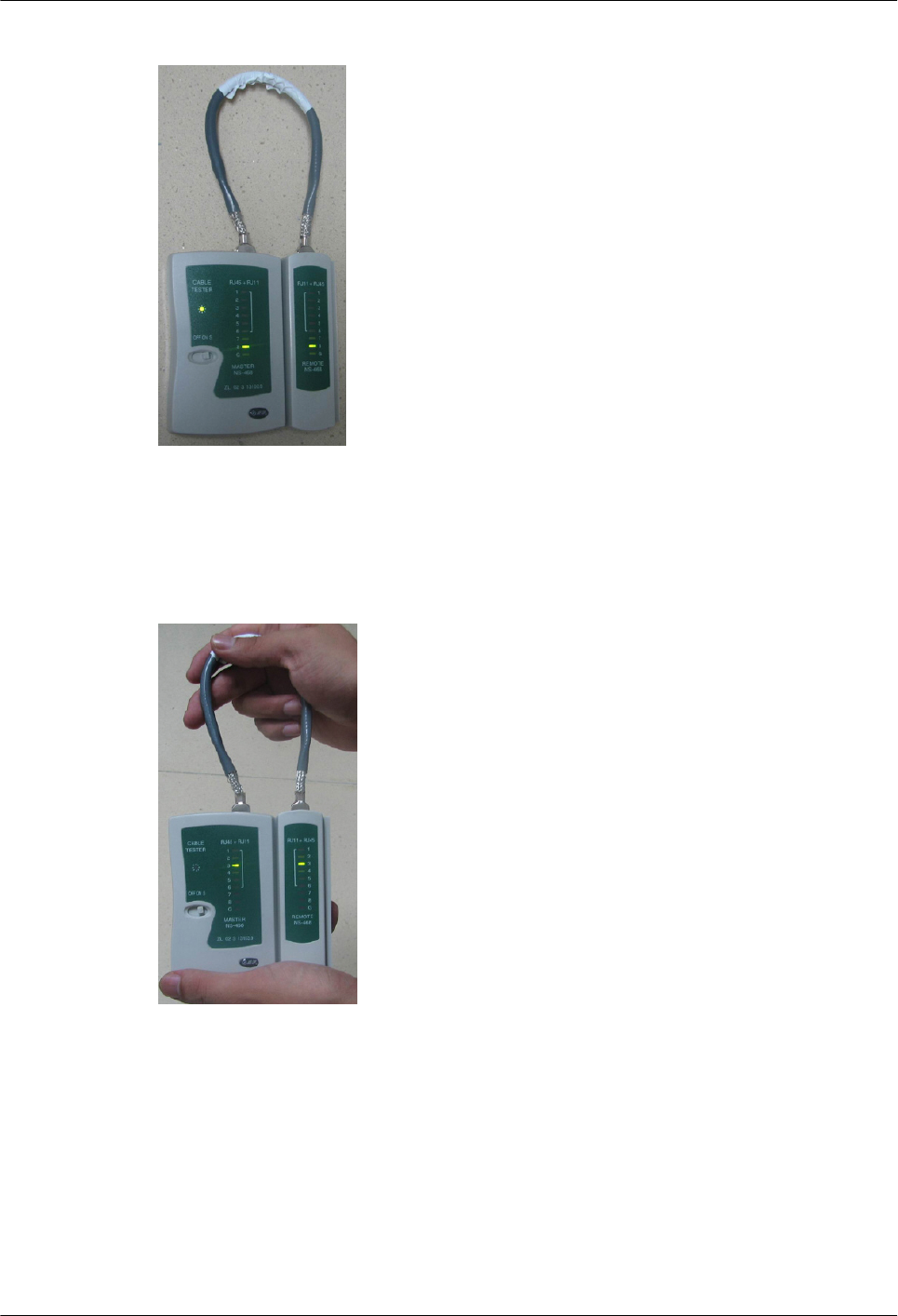
Figure 5-39 Testing the conduction and connections of wires
Step 3 Gently shake the connector and repeat Step 2 to check whether the metal contact strips are in
good contact with the core wires and Ethernet ports, as shown in Figure 5-40.
Figure 5-40 Checking the reliability
The procedure for testing a crossover cable is the same as that for testing a straight-through cable
except for the sequence in which the indicators turn on. You need to refer to the wire connections
of a crossover cable.
The Ethernet cable is qualified if the indicators turn on in the following sequence:
At the master (left) section of the tester, the indicators turn on in the sequence of 1-8-G. At the
slave (right) section of the tester, the indicators turn on in the sequence of 3-6-1-4-5-2-7-8-G.
Otherwise, the Ethernet cable is unqualified.
Huawei AP8030DN & AP8130DN
Hardware Installation and Maintenance Guide 5 Appendix
Issue 03 (2015-05-18) Huawei Proprietary and Confidential
Copyright © Huawei Technologies Co., Ltd.
72
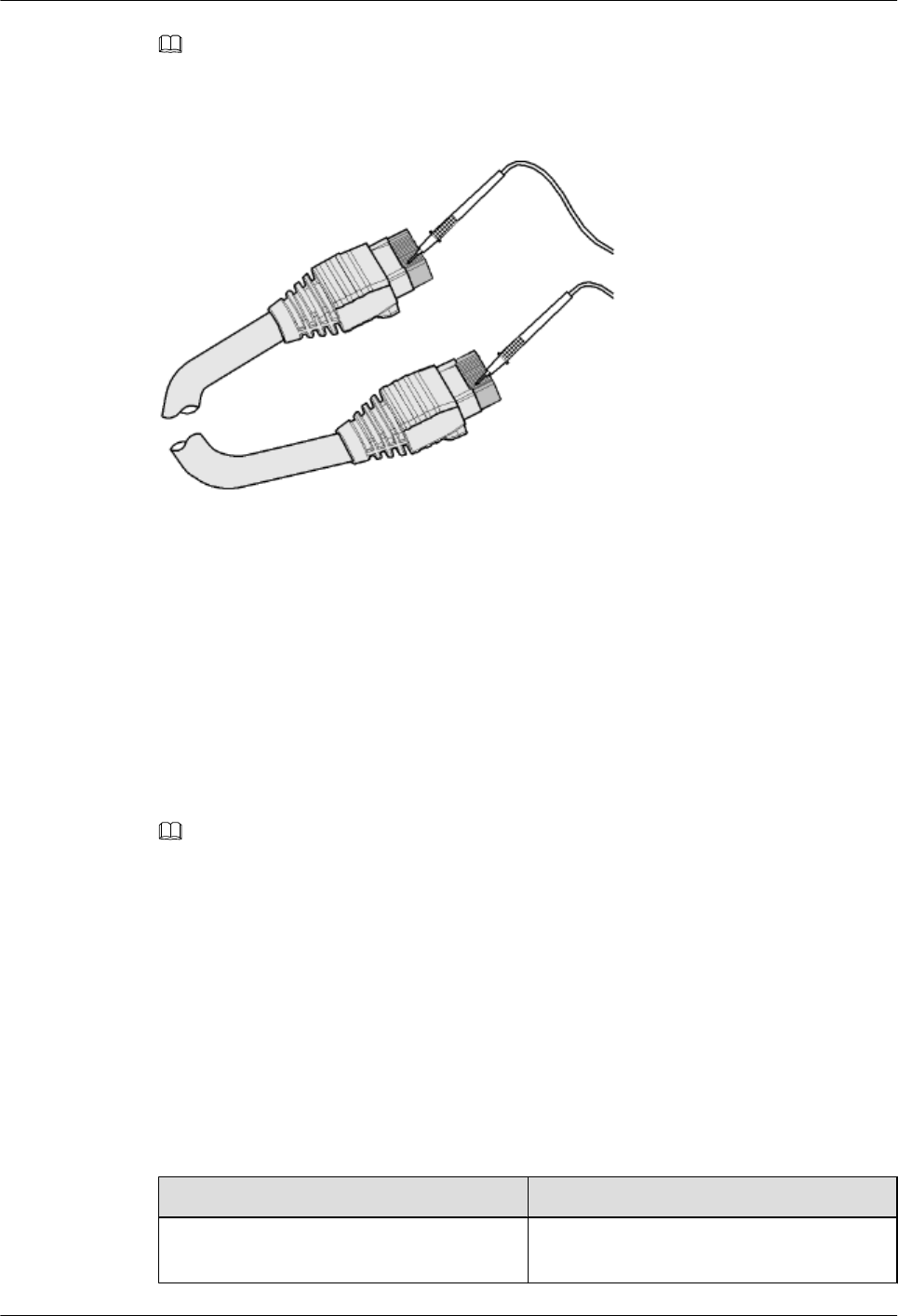
NOTE
If a tester is not available, you can use a multimeter to perform a simple test, as shown in Figure 5-41.
Figure 5-41 Testing the connection of an Ethernet cable
----End
5.1.4 Installing Cable Accessories
Precautions for Installing Cable Accessories
Tools
NOTE
The illustrations in this document may differ from actual situations, but the installation methods remain
the same. For example, in this document, the adapters of cable connectors have separate interfaces. In the
actual situation, the adapters may have interfaces fixed on equipment.
Use dedicated tools provided or specified by Huawei and follow the installation procedure
described here.
Bending Radius
Unless otherwise specified, bending radiuses (R) of cables or fibers must meet the requirements
listed in Table 5-9.
Table 5-9 Bending radiuses of cables or fibers
Cable or Fiber Bending Radius (R)
Ordinary cable In normal cases, R ≥ 2d. When the cable is
connected with a connector, R ≥ 5d.
Huawei AP8030DN & AP8130DN
Hardware Installation and Maintenance Guide 5 Appendix
Issue 03 (2015-05-18) Huawei Proprietary and Confidential
Copyright © Huawei Technologies Co., Ltd.
73

Cable or Fiber Bending Radius (R)
Fiber R ≥ 40 mm (1.57 in.); Bending angle > 90°
NOTE
The letter d indicates the diameter of a cable or fiber.
Precautions for Installation
lHold the terminals of cables instead of pulling the cables when installing or removing the
cable components.
lDo not insert a connector forcibly when the connector is blocked. Pull out the connector
by using a dedicated tool. Install the connector again after you check that the pins are
inserted properly.
lBefore tightening screws on cable connectors, ensure that the connectors are properly
connected to their adapters. Tighten the screw with appropriate force using a flat-head or
Phillips screwdriver instead of bare hands or an electric screwdriver. If the screw cannot
be screwed into the tapped hole, find out the reason and try again. Do not screw it with too
much force, or the screw or adapter may be damaged.
lWhen removing densely aligned cables or fiber connectors, use dedicated pliers such as
cable-pulling pliers and fiber-pulling pliers.
lDo not twist, bend, stretch, or extrude fibers during installation.
lCover the fiber connectors that are not in use by using dustproof caps. Remove the dustproof
caps before using the fiber connectors.
Requirements for Cable Routing
lTo protect cables, remove the burrs in the cable through-holes or install protective rings in
the holes.
lTo ease the connection and to avoid stress, keep slack at cable joints. After connecting
multiple cables to a connector that has multiple interfaces, keep the cables slack to avoid
stress generation.
lBind or clean cables gently because cable distortion affects signal quality.
lKeep cables away from moveable components such as doors.
lSharp objects must not be touched in cable wiring to ensure that cables are not damaged.
lTo protect power cables, power cables of the active and standby power modules are laid
separately.
Installing Power Adapters
Installing the OT Terminal
Huawei AP8030DN & AP8130DN
Hardware Installation and Maintenance Guide 5 Appendix
Issue 03 (2015-05-18) Huawei Proprietary and Confidential
Copyright © Huawei Technologies Co., Ltd.
74
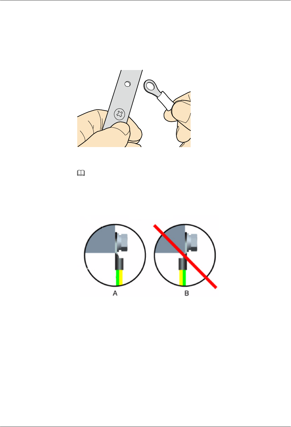
Procedure
lInstall an OT terminal.
1. Align the hole of the OT terminal (conductor upward) with a connecting hole, as shown
in Figure 5-42.
Figure 5-42 Aligning the OT terminal with a connecting hole
NOTE
When you install an OT terminal, the crimping sleeve is installed as shown in Figure 5-43,
where A is correct and B is wrong.
Figure 5-43 Installing an OT terminal, showing the orientation of crimping sleeve
2. Place the spring washer and flat washer in turn, mount a matching screw, and fasten
it clockwise, as shown in Figure 5-44.
Huawei AP8030DN & AP8130DN
Hardware Installation and Maintenance Guide 5 Appendix
Issue 03 (2015-05-18) Huawei Proprietary and Confidential
Copyright © Huawei Technologies Co., Ltd.
75
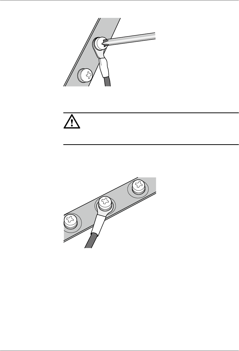
Figure 5-44 Installing two terminals back to back
NOTICE
Ensure that the OT terminal is not in contact with other terminals or metal components.
3. Move the cable slightly and ensure that it is securely connected, as shown in Figure
5-45.
Figure 5-45 Installed OT terminal
lInstall two OT terminals on a post.
Before you install two OT terminals on a post, ensure that the two terminals can be installed
on the post and that the electrical connecting pieces have a large contact area. Two OT
terminals can be installed using any of these methods:
–Bend the upper OT terminal at a 45- or 90-degree angle, as shown in Figure 5-46.
–Cross the two terminals, as shown in Figure 5-47.
Huawei AP8030DN & AP8130DN
Hardware Installation and Maintenance Guide 5 Appendix
Issue 03 (2015-05-18) Huawei Proprietary and Confidential
Copyright © Huawei Technologies Co., Ltd.
76
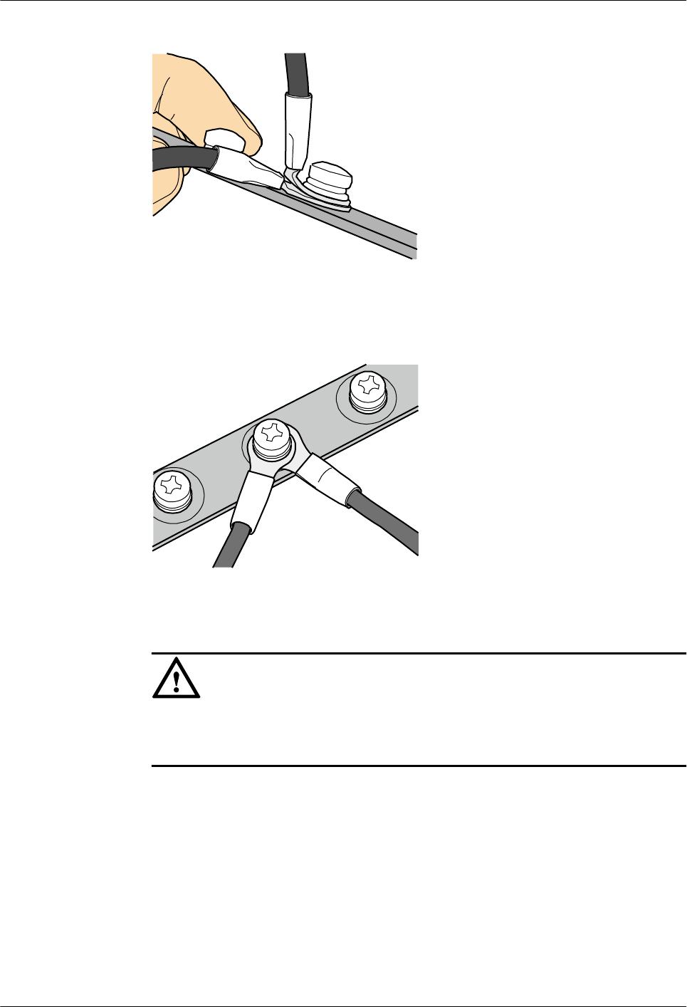
Figure 5-46 Bending the upper OT terminal at a 45- or 90-degree angle
Figure 5-47 Crossing two terminals
NOTICE
If the two terminals are different in size, place the smaller one above the bigger one. A
maximum of two terminals can be installed on a post.
lTo remove an OT terminal, loosen the screw in the counterclockwise direction.
----End
Installing the Cord End Terminal
Procedure
Step 1 Hold a cord end terminal upright and place it on a terminal jack, as shown in Figure 5-48. To
ensure bump contact and dense connection, place the plain side of the terminal outwards.
Huawei AP8030DN & AP8130DN
Hardware Installation and Maintenance Guide 5 Appendix
Issue 03 (2015-05-18) Huawei Proprietary and Confidential
Copyright © Huawei Technologies Co., Ltd.
77
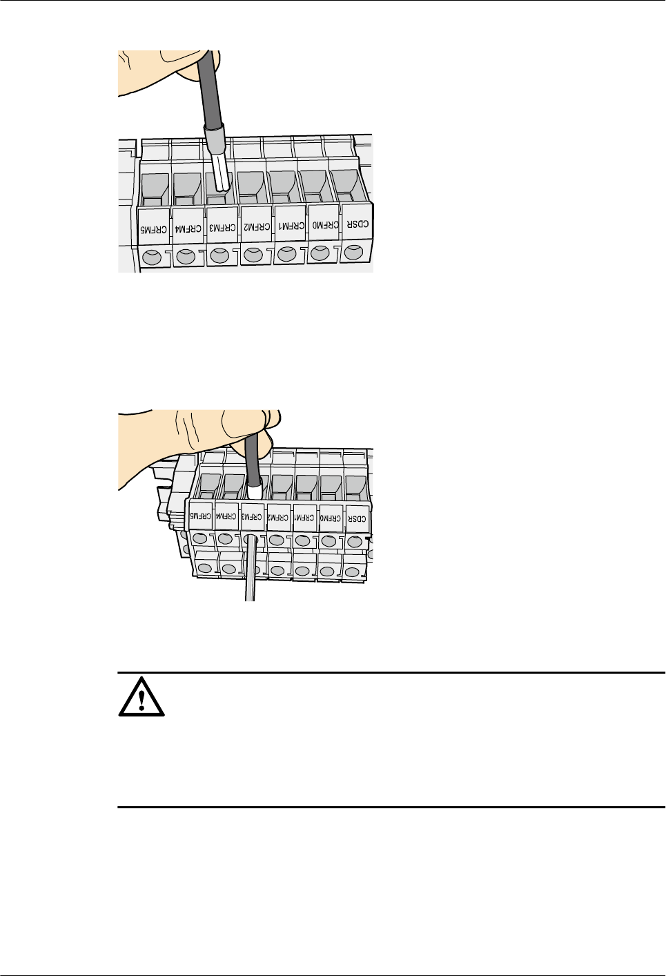
Figure 5-48 Placing a terminal on a terminal jack vertically
Step 2 Insert the terminal into the jack vertically, and fasten the terminal by turning the matching screw
in the clockwise direction, as shown in Figure 5-49.
Figure 5-49 Feeding the terminal into the jack
NOTICE
lEnsure that the exposed section of the terminal should be less than 2 mm (0.079 in.) in length.
lDo not press the insulation of the terminal.
lInsert only one terminal into one jack.
Step 3 Move the cable slightly and ensure that it is securely connected.
Step 4 Before you remove a cord end terminal, loosen the screw in the counterclockwise direction.
----End
Installing Ethernet Adapters
Huawei AP8030DN & AP8130DN
Hardware Installation and Maintenance Guide 5 Appendix
Issue 03 (2015-05-18) Huawei Proprietary and Confidential
Copyright © Huawei Technologies Co., Ltd.
78
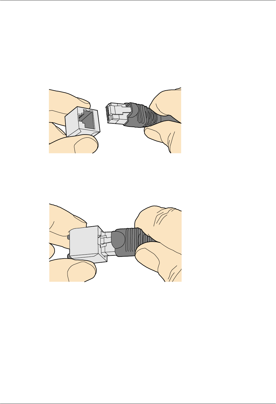
Installing a Shielded Ethernet Connector
Procedure
Step 1 Hold the male and female connectors, with the male connector facing the female connector, as
shown in Figure 5-50.
Figure 5-50 Holding the male and female shielded connectors
Step 2 Insert the male connector into the female connector, as shown in Figure 5-51.
Figure 5-51 Feeding the male shielded connector into the female shielded connector
Step 3 When you hear a click, the cable connector is completely inserted in the port. (The clip on the
cable connector pops up to fix the connector in the port.) Pull the connector slightly and ensure
that it is securely connected, as shown in Figure 5-52.
Huawei AP8030DN & AP8130DN
Hardware Installation and Maintenance Guide 5 Appendix
Issue 03 (2015-05-18) Huawei Proprietary and Confidential
Copyright © Huawei Technologies Co., Ltd.
79
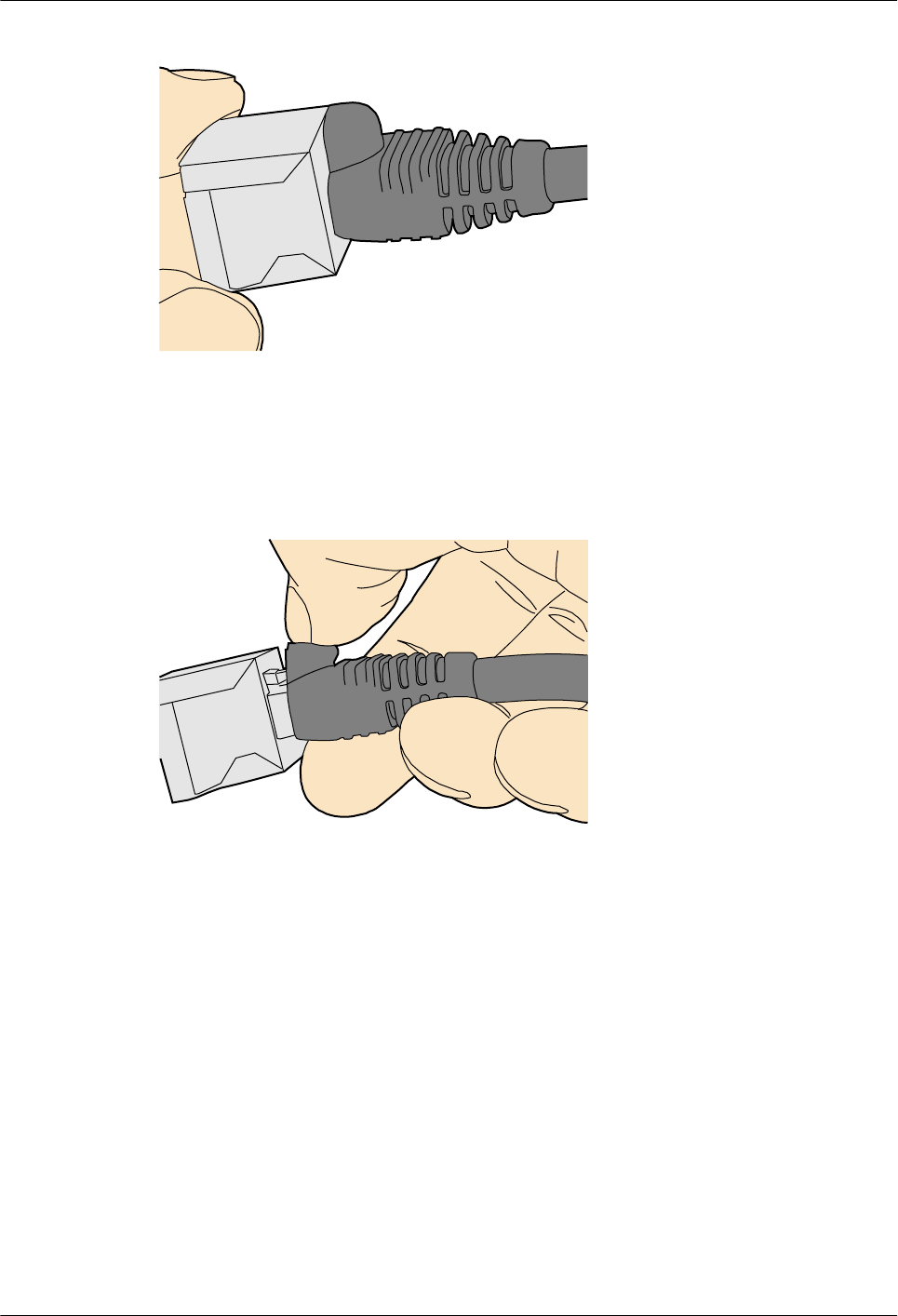
Figure 5-52 Installed shielded Ethernet connector
Step 4 To remove an Ethernet connector, press the locking key and pull out the connector, as shown in
Figure 5-53.
Figure 5-53 Removing an shielded Ethernet connector
----End
Installing an Unshielded Ethernet Connector
Procedure
Step 1 Hold the male and female connectors, with the male connector facing the female connector, as
shown in Figure 5-54.
Huawei AP8030DN & AP8130DN
Hardware Installation and Maintenance Guide 5 Appendix
Issue 03 (2015-05-18) Huawei Proprietary and Confidential
Copyright © Huawei Technologies Co., Ltd.
80
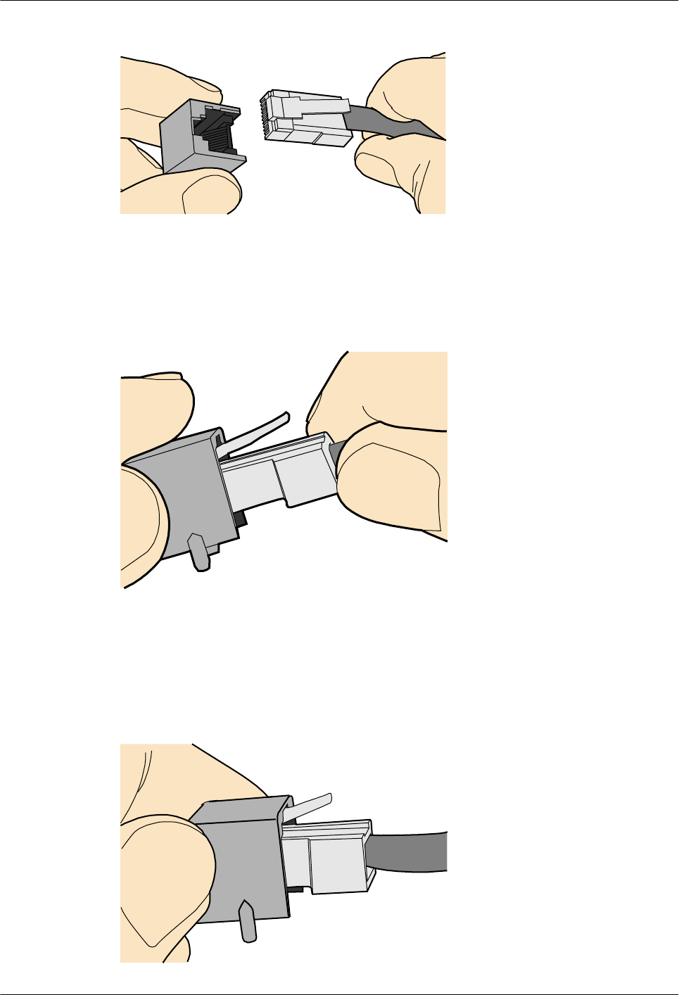
Figure 5-54 Holding the male and female unshielded connectors
Step 2 Feed the male connector into the female connector, as shown in Figure 5-55.
Figure 5-55 Feeding the male connector into the female unshielded connector
Step 3 A crisp click indicates that the connector is locked by the locking key. Pull the connector slightly
and ensure that it is securely connected. Figure 5-56 shows an installed Ethernet connector.
Figure 5-56 Installed unshielded Ethernet connector
Huawei AP8030DN & AP8130DN
Hardware Installation and Maintenance Guide 5 Appendix
Issue 03 (2015-05-18) Huawei Proprietary and Confidential
Copyright © Huawei Technologies Co., Ltd.
81
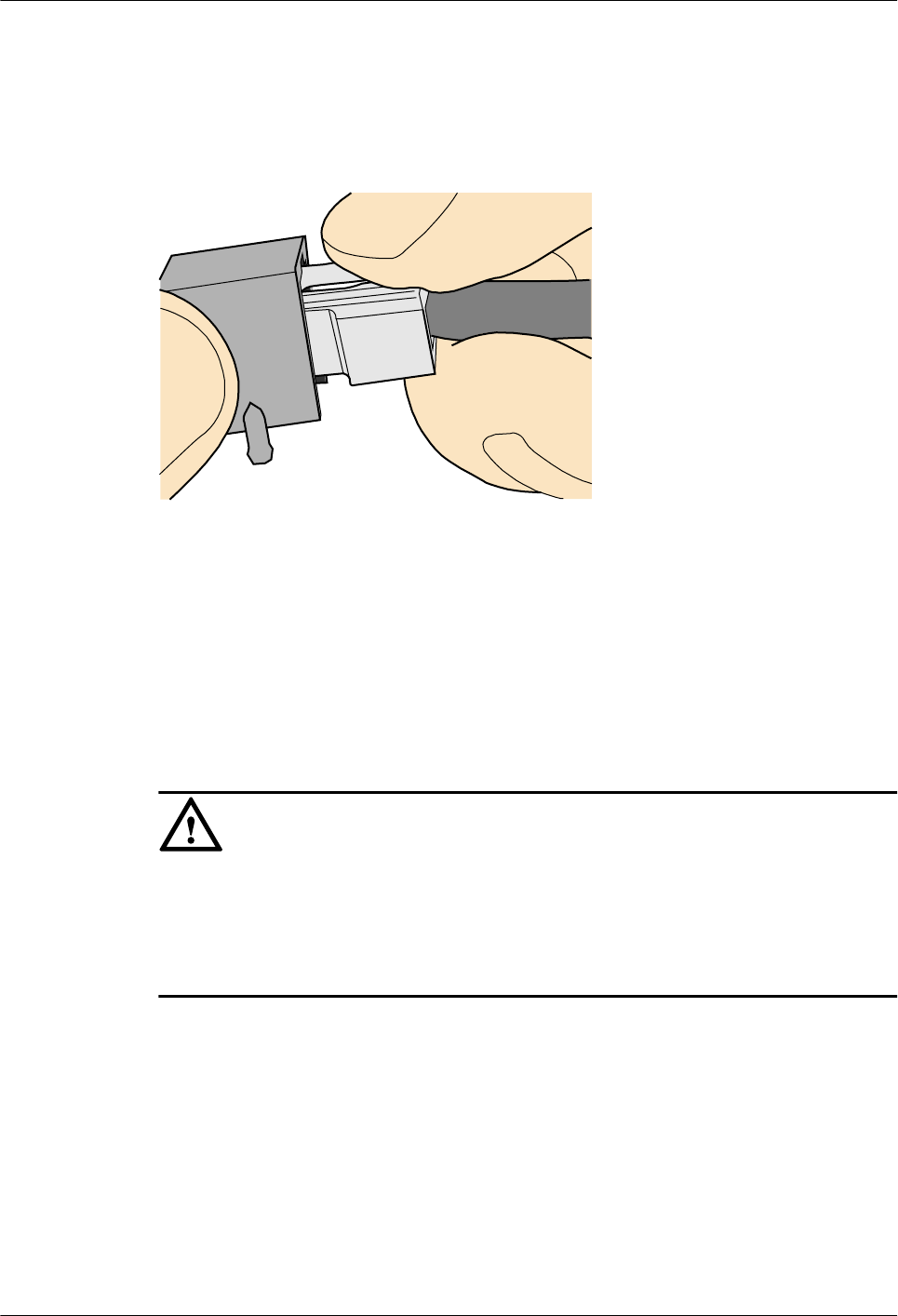
Step 4 To remove an Ethernet connector, press the locking key and pull out the connector, as shown in
Figure 5-57.
Figure 5-57 Removing an unshielded Ethernet connector
----End
Installing Fiber Connectors
Context
NOTICE
lAfter you remove the dustproof cap, ensure that the fiber pins are clean and install them as
soon as possible.
lWhen you disassemble fiber connectors, you must use a dedicated tool if the connectors are
densely installed.
Cleaning Fiber Connectors
Procedure
Step 1 Clean the pins of a fiber connector by using lint-free cotton and alcohol.
Step 2 Clean the pins again by using dust-free cotton. If necessary, clean the pins by using an air gun.
Ensure that the pins are free from any fiber or debris.
----End
Huawei AP8030DN & AP8130DN
Hardware Installation and Maintenance Guide 5 Appendix
Issue 03 (2015-05-18) Huawei Proprietary and Confidential
Copyright © Huawei Technologies Co., Ltd.
82
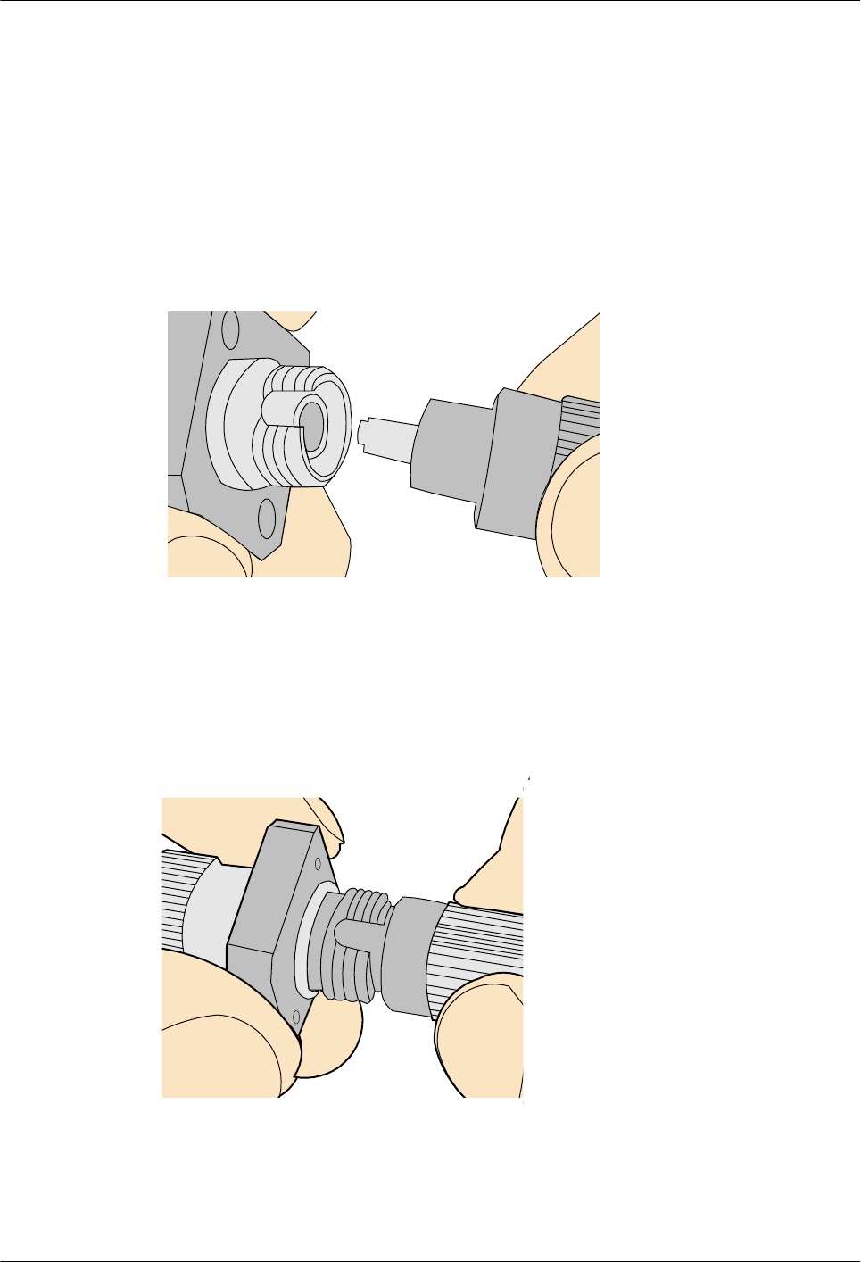
Installing an FC Fiber Connector
Procedure
Step 1 Remove the dustproof cap of the FC connector and store it for future use.
Step 2 Align the core pin of the male connector with that of the female connector, as shown in Figure
5-58.
Figure 5-58 Aligning the male connector with the female connector
Step 3 Align the male connector with the female connector and gently push the male connector until it
is completely seated in the female connector, as shown in Figure 5-59.
Figure 5-59 Feeding the male connector into the female connector
Step 4 Fasten the locking nut in the clockwise direction and ensure that the connector is securely
installed, as shown in Figure 5-60.
Huawei AP8030DN & AP8130DN
Hardware Installation and Maintenance Guide 5 Appendix
Issue 03 (2015-05-18) Huawei Proprietary and Confidential
Copyright © Huawei Technologies Co., Ltd.
83
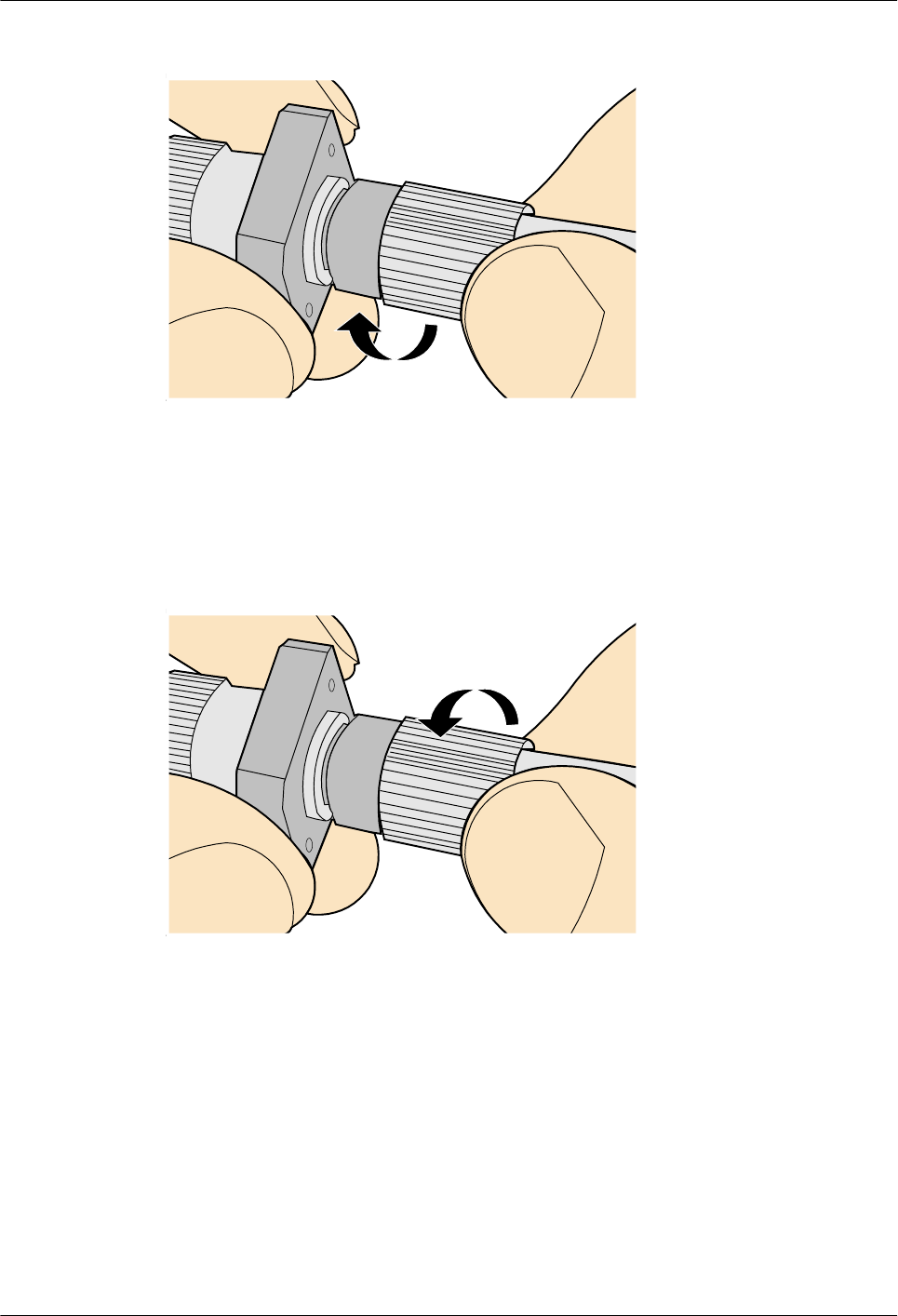
Figure 5-60 Fastening the locking nut
Step 5 To disassemble an FC fiber connector, loosen the locking nut counterclockwise, and gently pull
the male connector, as shown in Figure 5-61.
Figure 5-61 Disassembling an FC fiber connector
----End
Installing an LC Fiber Connector
Procedure
Step 1 Remove the dustproof cap of the LC fiber connector and store it for future use.
Step 2 Align the core pin of the male connector with that of the female connector, as shown in Figure
5-62.
Huawei AP8030DN & AP8130DN
Hardware Installation and Maintenance Guide 5 Appendix
Issue 03 (2015-05-18) Huawei Proprietary and Confidential
Copyright © Huawei Technologies Co., Ltd.
84
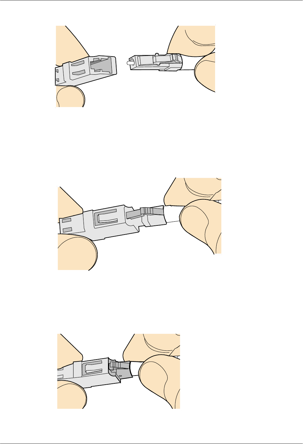
Figure 5-62 Aligning the male connector with the female connector
Step 3 Align the male connector with the fiber adapter and gently push the male connector until it is
completely seated in the fiber connector, as shown in Figure 5-63.
Figure 5-63 Feeding the male connector into the female connector
Step 4 A clicking sound indicates that the male connector is locked, as shown in Figure 5-64.
Figure 5-64 Installed LC connector
Huawei AP8030DN & AP8130DN
Hardware Installation and Maintenance Guide 5 Appendix
Issue 03 (2015-05-18) Huawei Proprietary and Confidential
Copyright © Huawei Technologies Co., Ltd.
85
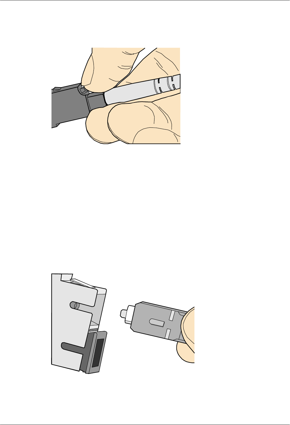
Step 5 To disassemble an LC fiber connector, press the locking nut to release the locking clips from
the bore, and gently pull the male connector, as shown in Figure 5-65.
Figure 5-65 Disassembling an LC fiber connector
----End
Installing the SC Fiber Connector
Procedure
Step 1 Remove the dustproof cap of the SC fiber connector and store it for future use.
Step 2 Align the core pin of the male connector with that of the female connector, as shown in Figure
5-66.
Figure 5-66 Aligning the male connector with the female connector
Step 3 Feed the fiber connector into the female connector, with your fingers holding the shell of the
fiber connector (not the pigtail). When you hear a click, the fiber connector is secured by the
Huawei AP8030DN & AP8130DN
Hardware Installation and Maintenance Guide 5 Appendix
Issue 03 (2015-05-18) Huawei Proprietary and Confidential
Copyright © Huawei Technologies Co., Ltd.
86
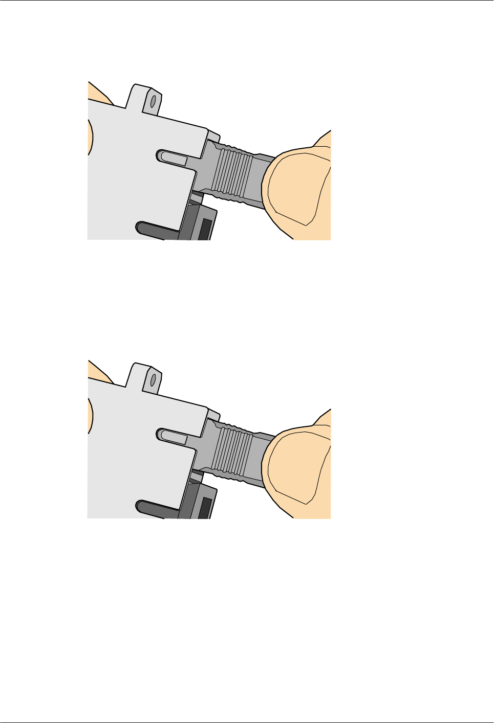
clips (internal parts, not illustrated in the figure). Pull the fiber connector gently. If the connector
does not loosen, the installation is complete. See Figure 5-67.
Figure 5-67 Installed SC fiber connector
Step 4 To disassemble an SC fiber connector, hold the shell of the connector (do not hold the fiber) and
gently pull the connector in the direction vertical to the adapter. Unlock the male connector, and
then separate it from the shell, as shown in Figure 5-68.
Figure 5-68 Disassembling an SC fiber connector
----End
Installing an MPO Connector
Procedure
Step 1 Remove the dustproof cap of the MPO fiber connector and store it for future use.
Step 2 Align the core pin of the male connector with that of the female connector, as shown in Figure
5-69.
Huawei AP8030DN & AP8130DN
Hardware Installation and Maintenance Guide 5 Appendix
Issue 03 (2015-05-18) Huawei Proprietary and Confidential
Copyright © Huawei Technologies Co., Ltd.
87
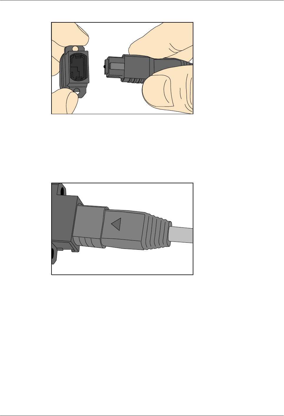
Figure 5-69 Aligning the male connector with the female connector
Step 3 Hold the shell labeled "PUSH" and feed the male connector into the female connector until you
hear a clicking sound. The male and female connectors are securely installed, as shown in Figure
5-70.
Figure 5-70 Installed MPO fiber connector
Step 4 To disassemble an MPO fiber connector, hold the shell labeled "PULL" and remove the male
connector, as shown in Figure 5-71.
Huawei AP8030DN & AP8130DN
Hardware Installation and Maintenance Guide 5 Appendix
Issue 03 (2015-05-18) Huawei Proprietary and Confidential
Copyright © Huawei Technologies Co., Ltd.
88
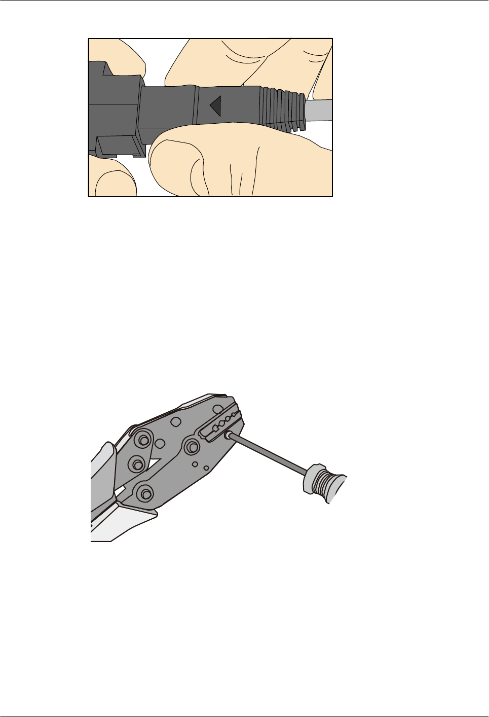
Figure 5-71 Disassembling an MPO fiber connector
----End
5.1.5 Replacing the Mold of the Crimping Pliers
Procedure
Step 1 Hold the handles of a pair of COAX crimping tools. Loosen the two fastening screws in the
counterclockwise direction, as shown in Figure 5-72.
Figure 5-72 Loosening two fastening screws
Step 2 Hold the handles of the COAX crimping tools to open the self-locking mechanism. The jaw of
the COAX crimping tools opens automatically, as shown in Figure 5-73.
Huawei AP8030DN & AP8130DN
Hardware Installation and Maintenance Guide 5 Appendix
Issue 03 (2015-05-18) Huawei Proprietary and Confidential
Copyright © Huawei Technologies Co., Ltd.
89
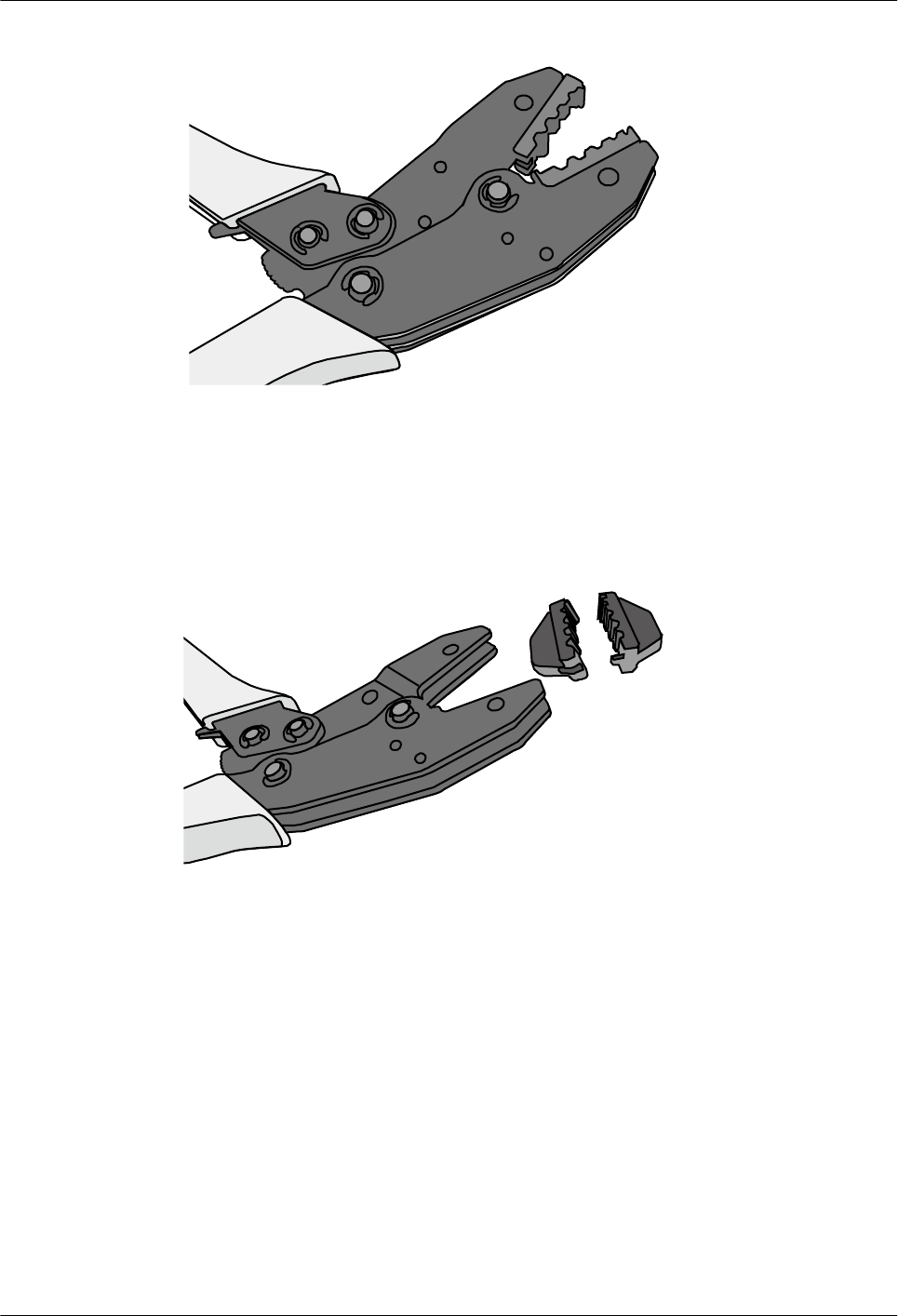
Figure 5-73 Pliers jaw opening automatically
Step 3 Remove the mould from the COAX crimping tools, as shown in Figure 5-74.
Figure 5-74 Removing the mould from the COAX crimping tools
Step 4 Place the mould to be installed into the jaw of the COAX crimping tools and align the screw
holes, as shown in Figure 5-75.
Huawei AP8030DN & AP8130DN
Hardware Installation and Maintenance Guide 5 Appendix
Issue 03 (2015-05-18) Huawei Proprietary and Confidential
Copyright © Huawei Technologies Co., Ltd.
90
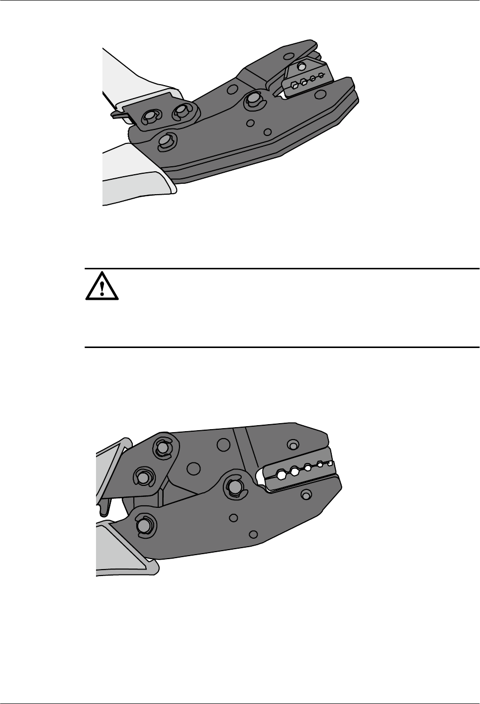
Figure 5-75 Installing a new mould in the COAX crimping tools
NOTICE
Keep the short side of the mould inwards and the long side outwards, with the teeth of the mould
aligning from the larger size to the smaller size.
Step 5 Hold the handles of the COAX crimping tools tightly to match the mould and the jaw completely.
Align the screw holes, as shown in Figure 5-76.
Figure 5-76 Aligning the screw holes
Step 6 Hold the handles of the COAX crimping tools with one hand. Tighten the two fastening screws
in the clockwise direction. Figure 5-77 and Figure 5-78shows the mould installed in the COAX
crimping tools.
Huawei AP8030DN & AP8130DN
Hardware Installation and Maintenance Guide 5 Appendix
Issue 03 (2015-05-18) Huawei Proprietary and Confidential
Copyright © Huawei Technologies Co., Ltd.
91
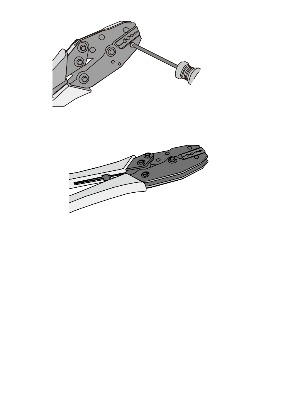
Figure 5-77 Mold installed in the COAX crimping tools
Figure 5-78 An installed mold
----End
5.2 Environmental Requirements for Device Operation
5.2.1 Environmental Requirements for an Equipment Room
Requirements for Selecting a Site for an Equipment Room
When designing a project, consider the communication network planning and technical
requirements of the equipment. Also consider hydrographic, geological, seismic, power supply,
and transportation factors.
Construction, structure, heating and ventilation, power supply, lighting and fire fighting of the
equipment room should be designed by specialized construction designers to suit the
environmental requirements of devices. The equipment room should also follow local
regulations concerning the industrial construction, environmental protection, fire fighting, and
civil air defense. Construction must conform to government standards, regulations, and other
requirements.
Huawei AP8030DN & AP8130DN
Hardware Installation and Maintenance Guide 5 Appendix
Issue 03 (2015-05-18) Huawei Proprietary and Confidential
Copyright © Huawei Technologies Co., Ltd.
92

The equipment room should be located at a place free from high temperature, dust, toxic gases,
explosive materials, or unstable voltage. Keep the equipment room away from significant
vibrations or strong noises, as well as power transformer stations.
The specific requirements for selecting a site for equipment room are as follows:
lThe room should be located at a distance of at least 5 km (3.11 mi.) from heavy pollution
sources such as smelting and coal mines. It should be located at a distance of at least 3.7
km (2.30 mi.) from moderate pollution sources such as chemical, rubber, and galvanization
factories. It should be located at a distance of at least 2 km (1.24 mi.) from light pollution
sources such as packinghouses and tanyards. If these pollution sources cannot be avoided,
ensure that the equipment room is upwind of the pollution sources. In addition, adopt a
high-quality equipment room or protection products.
lThe room should be located away from livestock farms, or in the upwind of the livestock
farms. Do not use an old livestock room or fertilizer warehouse as the equipment room.
lThe equipment room must be far away from the residential areas. The equipment room that
is not far away from the residential areas must comply with equipment room construction
standards to avoid noise pollution.
lThe doors and windows of the equipment room must be closed to keep an airtight room.
lUsing steel doors to ensure sound insulation is recommended.
lNo cracks or openings are allowed on the walls or floors. The outlet holes on the walls or
windows must be sealed. Walls must be constructed in the smooth, wear-resistant, dustproof
principles and produce the effect of flame retardant, sound insulation, heat absorption, dust
decrease, and electromagnetic shielding.
lThe air vent of the room should be far from the exhaust of city waste pipes, big cesspools
and sewage treatment tanks. The room should be in the positive pressure state to prevent
corrosive gases from entering the equipment room and corroding components and circuit
boards.
lThe room should be located far away from industrial and heating boilers.
lIt is recommended that the room be on or above the second floor. If this requirement cannot
be met, the ground for equipment installation in the room should be at least 600 mm (23.62
in,) above the maximum flood level.
lThe room should be at least 3.7 km (2.30 mi.) away from the seaside or salt lake. Otherwise,
the equipment room should be airtight with cooling facilities. In addition, alkalized soil
cannot be used as the construction material. Otherwise, equipment suitable for wet
conditions must be used.
lThe equipment room should be strong enough to resist winds and downpours.
lThe room should be located away from dusty roads or sand. If this is unavoidable, the doors
and windows of the equipment room must not face pollution sources.
lDo not place air conditioning vents near the equipment so that they blow directly on the
equipment because condensation may be blown into the equipment.
lDo not use decorative materials that contain sulfur in the equipment room.
Equipment Room Layout
The equipment room is usually used to install mobile switching equipment, telecom transmission
equipment and power supply equipment as well as other auxiliary equipment. To ensure easy
maintenance and management, place the telecom equipment in different rooms. Figure 5-79
shows the layout of the equipment room.
Huawei AP8030DN & AP8130DN
Hardware Installation and Maintenance Guide 5 Appendix
Issue 03 (2015-05-18) Huawei Proprietary and Confidential
Copyright © Huawei Technologies Co., Ltd.
93
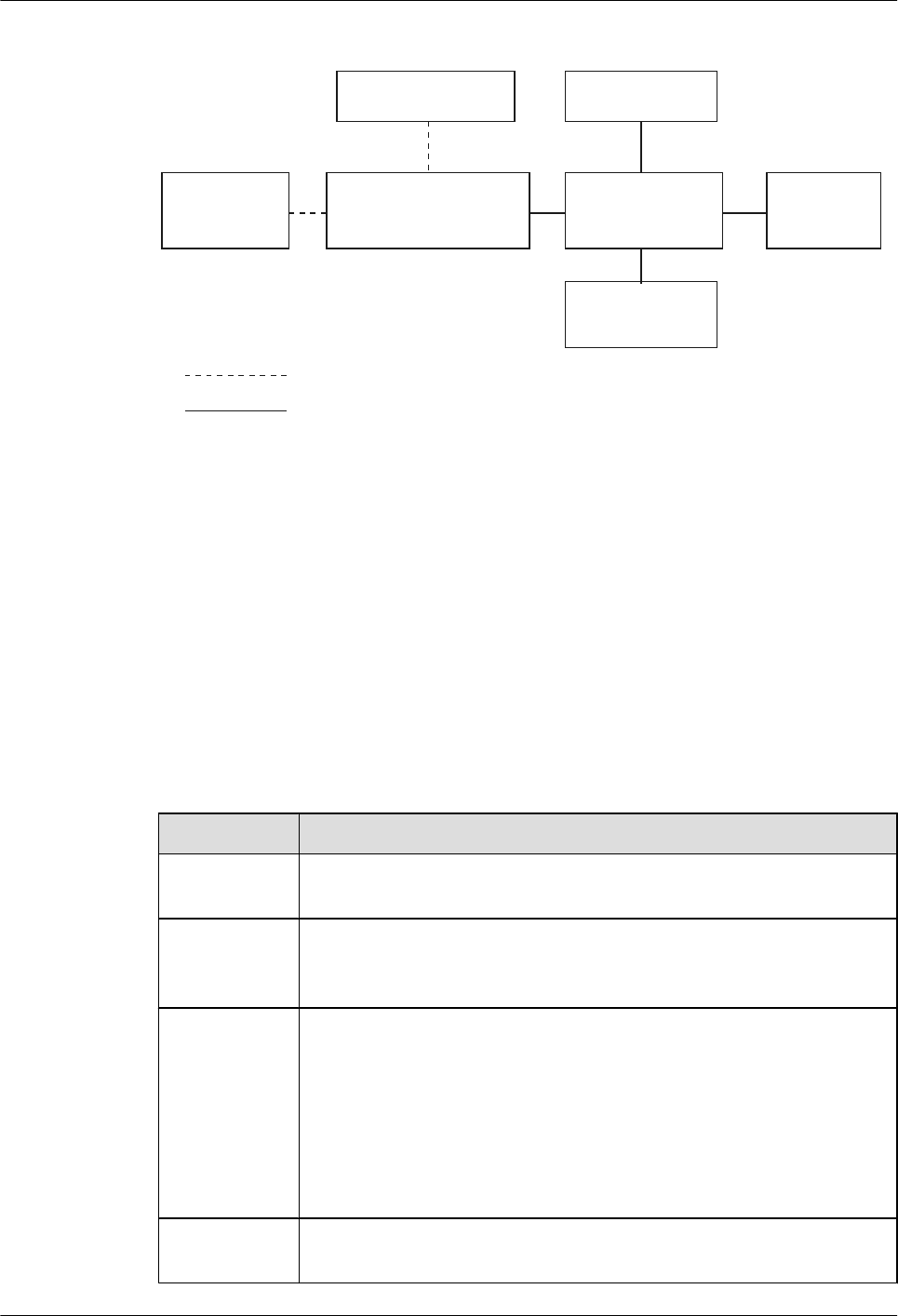
Figure 5-79 Layout of the equipment room
Control room Generator room
Transmission
room
Main communication
equipment room
Power distribution
room Battery room
Substation room
Communication cable and optical cable
Power cable
The general layout principles of the equipment room are as follows:
lIt should meet requirements for laying out and maintaining communication cables and
power cables.
lIt should reduce the cabling distance, which eases cable maintenance, reduces potential
communication faults, and maximizes efficiency.
Construction Requirements for the Equipment Room
Table 5-10 shows the construction requirements for the equipment room.
Table 5-10 Construction requirements for the equipment room
Item Requirements
Area The smallest area of the equipment room can accommodate the equipment
with the largest capacity.
Net height The minimum height of the equipment room should not be less than 3 m
(9.84 ft). The minimum height of the equipment room is the net height
below overhead beams or ventilation pipes.
Floor The floor in the equipment room should be semi-conductive and dustproof.
A raised floor with an ESD covering is recommended. Cover the raised
floor tightly and solidly. The horizontal tolerance of each square meter
should be less than 2 mm (0.08 in.). If raised floors are unavailable, use a
static-electricity-conductive floor material, with a volume resistivity of 1.0
x 107 ohms to 1.0 x 10¹⁰ ohms. Ground this floor material or raised floor.
You can connect them to ground using a one megohm current-limiting
resistor and connection line.
Load-bearing
capacity
The floor must bear loads larger than 150 kg/m2 (0.21 bf/in.2).
Huawei AP8030DN & AP8130DN
Hardware Installation and Maintenance Guide 5 Appendix
Issue 03 (2015-05-18) Huawei Proprietary and Confidential
Copyright © Huawei Technologies Co., Ltd.
94
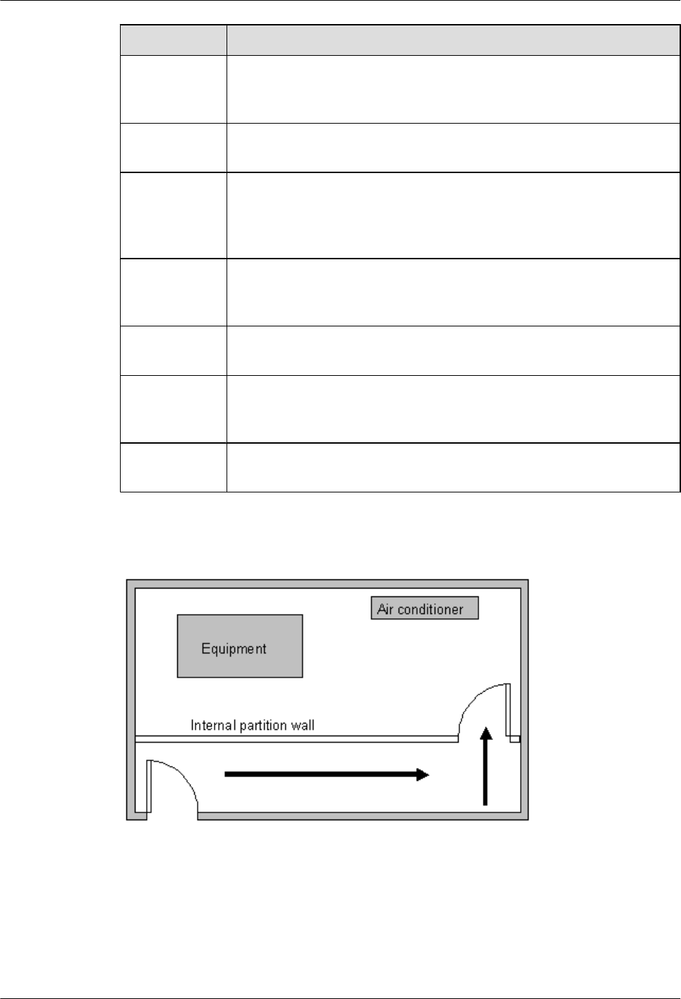
Item Requirements
Door and
windows
The door of the equipment room should be 2 m (6.56 ft) high and 1 m (3.28
ft) wide. One door is enough. Seal the doors and windows with dustproof
plastic tape. Use double-pane glass in the windows and seal them tightly.
Wall surface
treatment
Paste wallpaper on the wall or apply flat paint. Do not use pulverized paint.
Cable trays Use cable trays to arrange cables. The inner faces of the cable trays must
be smooth. The reserved length and width of the cable trays, and the number,
position and dimensions of the holes must comply with the requirements
of device arrangement.
Water pipe Do not pass service pipes, drainpipes, and storm sewers through the
equipment room. Do not place a fire hydrant in the equipment room, but
place it in the corridor or near the staircase.
Internal
partition wall
Separate the area where the equipment is installed from the equipment room
door. The partition wall can block some outside dust.
Installation
position of the
air conditioner
Install air conditioner vents so that the air does not blow directly on
equipment.
Other
requirements
Avoid the proliferation of mildew, and keep out rodents (like mice).
Figure 5-80 Internal partition wall inside the equipment room
Equipment Room Environment
Dust on devices may cause electrostatic discharge and result in poor contact for connectors or
metal connection points. This problem can shorten the life span of devices and cause faults.
Huawei AP8030DN & AP8130DN
Hardware Installation and Maintenance Guide 5 Appendix
Issue 03 (2015-05-18) Huawei Proprietary and Confidential
Copyright © Huawei Technologies Co., Ltd.
95
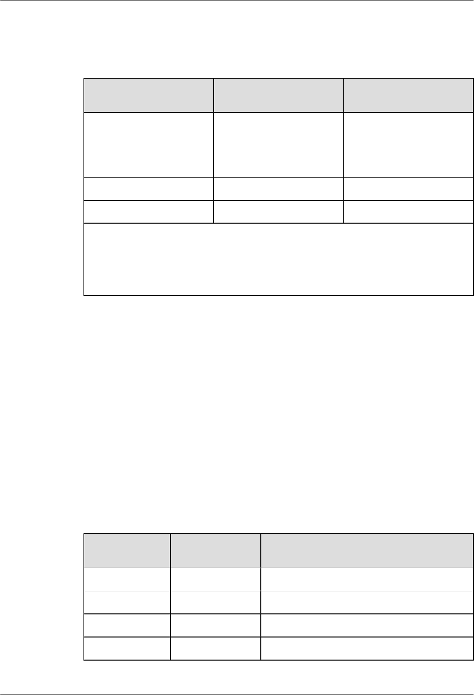
The equipment room must be free from explosive, conductive, magnetically-permeable, and
corrosive dust. Table 5-11 shows the requirement for dust concentration in the equipment room.
Table 5-11 Requirements for dust particles in the equipment room
Mechanical active
material
Unit Concentration
Dust particle Particle /m3≤ 3x 10⁴
(no visible dust accumulated
on a workbench in three
days)
Suspending dust mg/m3≤0.2
Precipitable dust mg/m2·h ≤1.5
Description
lDust particle diameter ≥ 5 µm
lSuspending dust diameter ≤ 75 µm
l75 µm ≤ precipitable dust diameter ≤ 150 µm
Take the following measures to meet the requirements:
lUse dustproof materials for ground, wall, and ceiling construction.
lUse screens on the door and windows facing outside. The outer windows should be dust-
proof.
lClean the equipment room regularly and clean the air filter monthly.
lWear shoe covers and ESD clothes before entering the equipment room.
Requirements for Corrosive Gases
The room should be free from dusts and corrosive gases, such as SO2, H2S, and NH3. Table
5-12 shows the requirements for the corrosive gas concentration.
Table 5-12 Requirements for corrosive gas concentration
Chemical active
material Unit Concentration
SO2mg/m3≤0.20
H2Smg/m3≤0.006
NH3mg/m3≤0.05
Cl2mg/m3≤0.01
Huawei AP8030DN & AP8130DN
Hardware Installation and Maintenance Guide 5 Appendix
Issue 03 (2015-05-18) Huawei Proprietary and Confidential
Copyright © Huawei Technologies Co., Ltd.
96

Take the following measures to meet the requirements:
lAvoid constructing the room near a place where the corrosive gas concentration is high,
such as a chemical plant.
lEnsure the air intake vent of the room is in the prevailing upwind direction from the
pollution source.
lPlace batteries in different rooms.
lA professional service should monitor the corrosive gas conditions regularly.
Requirements for ESD Prevention
The absolute value of electrostatic voltage is less than 1000 V.
Take the following measures to meet the requirements:
lTrain operators about ESD prevention.
lKeep the correct humidity level in the equipment room to reduce the impact of static
electricity.
lLay out an ESD floor in equipment rooms.
lWear ESD shoes and clothing before entering equipment room.
lUse ESD tools, such as wrist straps, tweezers, and pullers.
lGround all conductive materials in the room, including computer terminals. Use ESD
worktables.
lKeep non-ESD materials (such as common bags, foams, and rubbers) at least 30 cm (11.81
in.) away from boards and ESD-sensitive components.
Electromagnetism Requirements for the Equipment Room
All interference sources, inside or outside the equipment room, can cause equipment problems
with capacitive coupling, inductive coupling, electromagnetic wave radiation, and common
impedance (including grounding system) coupling. Prevent the interference using these
approaches:
lTake effective measures against electrical interference from the power supply system.
lDo not use the working ground of the equipment as the same ground for surge protection.
Separate them as far as possible.
lKeep the equipment far away from strong power radio transmitters, radar units, and high-
frequency and high-current equipment.
lUse electromagnetic shielding if necessary.
Requirements for Lightning Proof Grounding
Table 5-13 shows the requirements for lightning proof grounding.
Huawei AP8030DN & AP8130DN
Hardware Installation and Maintenance Guide 5 Appendix
Issue 03 (2015-05-18) Huawei Proprietary and Confidential
Copyright © Huawei Technologies Co., Ltd.
97

Table 5-13 Requirements for lightning proof grounding
Item Requirements
Capital
construction
lUse the reinforced concrete structure for the construction of the
equipment room.
lInstall the lightning proof device like a lighting rod in the room.
lThe lightning proof ground shares the same grounding body with the
protection ground of the room.
Power cables
leading in the
equipment room
need to be
equipped with a
surge arrester
lAfter the low-voltage power cables are led into the room, install the
surge arrester for the power cables in the AC voltage stabilizer and the
AC power distribution panel (box). Ground the arrester nearby and
correctly.
lFor the equipment room in the city, install the power supply arrester
with the nominal discharging current no less than 20 kA. For the
equipment room built in the suburbs subject to lightning strike, install
the power supply arrester with the nominal discharging current larger
than 60 kA. For the equipment room in the mountain areas easily
subject to lightning strike, or in the separate high-rise buildings in the
city, install the power supply arrester with the nominal discharging
current larger than 100 kA.
lThe ground cable of the surge arrester should be a maximum of 1 m
(3.28 ft) long.
Grounding of DC
power
distribution
lConnect the DC working ground (positive pole of the -48 V DC power
supply or the negative pole of the 24 V DC power supply) with the
indoor collective ground cable nearby. The total ground cable should
meet the maximum load of the equipment.
lThe power equipment must have the DC working ground cable, which
can connect the power equipment to the collective ground cable of the
telecommunication site (or the protection ground bar of the equipment
room).
Equipotential
connection
lGround the devices and auxiliary devices in the room such as mobile
base station, transmission, switching equipment, power supply
equipment, and cable distribution frame properly. Connect all PGND
cables to the collective protection ground bar. Connect all PGND
cables in one equipment room to one protection ground bar.
lApply joint grounding to the working ground and protection ground
of devices, which means the two share one grounding network.
lThe cable tray, rack or shell, metal ventilation pipe, metal door or
window of the equipment should be grounded for protection.
General
requirements for
grounding
lDo not connect the neutral line of the AC power cable with the
protection ground of any telecom equipment in the equipment room.
lDo not install the fuse or switch on the ground cable.
lAll ground cables should be as short as possible, and arranged directly.
Huawei AP8030DN & AP8130DN
Hardware Installation and Maintenance Guide 5 Appendix
Issue 03 (2015-05-18) Huawei Proprietary and Confidential
Copyright © Huawei Technologies Co., Ltd.
98

Item Requirements
Grounding
resistance
lThe grounding resistance must be lower than 1 ohm.
lThe upper end of the grounding body should be at least 0.7 m (2.30
ft) over the ground. In cold areas, bury the grounding body below the
frozen ground.
lMeasure the grounding resistance periodically to ensure effective
grounding.
Routing of signal
cable
lDo not arrange the signal cables overhead in the equipment room. All
signal cables must be led into the site underground.
lUse the cables with metal jacket or place them into the metal pipe if
they come out/in the equipment room.
lGround the idle lines inside the cable in the equipment room.
lSignal cables should be deployed on internal walls. Do not deploy
outdoor aerial cables.
lKeep signal cables away from power cables and surge protection
devices.
Collective
ground cable
lUse the grounding ring or ground bar for the collective ground cable.
lDo not use aluminum cables as ground cables. Adopt measures to
prevent electrification corrosion when connecting different metal
parts together.
lUse the copper busbar as the collective ground cable with the cross-
sectional area not less than 120 mm2 (0.19 in.2), or use the galvanized
flat steel of the same resistance. Insulate the collective ground cable
from the reinforcing steel bars of the building.
Grounding lead-
in
The grounding lead-in should be a maximum of 30 m (98.42 ft) long. Use
the galvanized flat steel with cross-sectional area of 40 mm x 4 mm (1.58
in. x 0.158 in.) or 50 mm x 5 mm (1.97 in. x 0.197 in.).
Huawei AP8030DN & AP8130DN
Hardware Installation and Maintenance Guide 5 Appendix
Issue 03 (2015-05-18) Huawei Proprietary and Confidential
Copyright © Huawei Technologies Co., Ltd.
99

Item Requirements
Grounding of the
cabinet
lAll the devices including the surge protection device in the cabinet
must be connected in an equipotential manner. The ground cables can
be aggregated to the ground bar or surge protector socket first, and
then the ground bar or surge protector socket is connected to the
ground.
lThe resistance tested using a multimeter between the device ground
terminals and ground bar cannot exceed 0.1 ohm.
lThe cabinet can be grounded using the protecting earthing (PE) wire
of the electrical network in the building, zinc-coated angle steel, or
main steel bar of the building.
lIf the cabinet is grounded using the PE wire of the electrical network,
the grounding status can be checked using a multimeter. If the voltage
between the PE wire and neutral wire is lower than 5 V and the voltage
between the PE wire and live wire is about 220 V, the PE wire is
grounded well. If the tested AC voltages are not within the ranges, the
cabinet must be grounded in other ways.
lThe yellow-green ground cable contains multiple copper wires. The
diameter is no smaller than 6 mm2 (0.0093 in.2) and the length cannot
exceed 3 m (9.84 ft.).
lGround cables cannot be twisted with signal cables.
lAntirust and anticorrosion measures must be taken on the ground
terminals.
lThe fiber reinforcing rib can be directly connected to the ground bar
of the cabinet. Before wrapping the reinforcing rib with insulation
tape, cut a 0.5 m (1.64 ft.) segment from the reinforcing rib. Wrap the
reinforcing rib with at least five layers of insulation tape. Keep the
reinforcing rib at least 5 cm (1.969 in.) from the cabinet surface.
5.2.2 Requirements for Power Supply
Requirements for AC Power Supply
The AC power supply consists of power mains, uninterruptable power supply (UPS), and self-
supplied electric generator. In addition to meeting the requirements of the server load, the AC
power supply must have a simple connection line, safe operation, flexible scheduling, and easy
maintenance.
The low-voltage power supply should have 3-phase, 5-wire mode or monophase 3-wire mode.
This AC power supply should be 110 V/220 V, and the frequency is 50 Hz.
The UPS should supply the same power and operate at the same phase as the power mains. The
switching time between the UPS and mains should be less than 10 ms; otherwise, the networking
devices will reboot or reset.
For power distribution capacity in the equipment room, both the working current and fault current
of the devices should be considered. Ensure that independent AC power supplies protect
Huawei AP8030DN & AP8130DN
Hardware Installation and Maintenance Guide 5 Appendix
Issue 03 (2015-05-18) Huawei Proprietary and Confidential
Copyright © Huawei Technologies Co., Ltd.
100
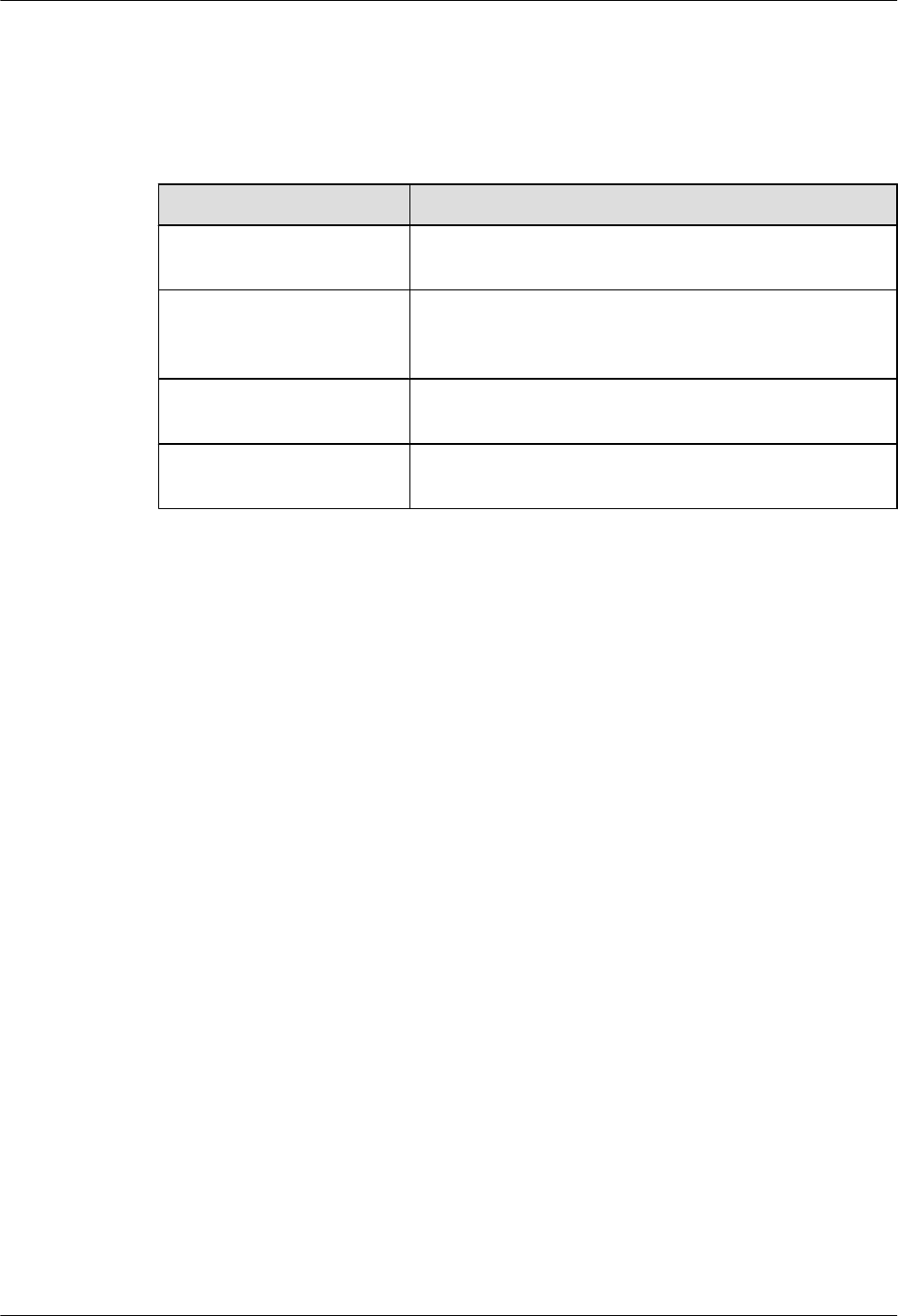
independent devices. Configure the current-carrying capacity of the protection switch of the
equipment room for more than that of the devices.
Table 5-14 shows the voltage range of the AC power supply for the devices.
Table 5-14 Voltage range of AC power supply
Item Requirements
AC power capacity to support
the devices
-10% to +5% of the rated voltage
AC power capacity to support
the power modules and
important buildings
-15% to +10% of the rated voltage
Frequency of alternating
current
-4% to +4% of the rated value
Voltage wave shape sine
distortion
Within 5% of the rated voltage
The automated electric generator must have a standard interface that supports
telecommunication protocol, remote telecommunication, monitoring, and control.
AC power cables should meet the following specifications:
lAC neutral should have a conductor with the same cross section as the phase line.
lAC cables should have non-flammable insulation. The layout of AC cables should comply
with local regulations. Low-voltage power distribution rooms should comply with local
regulations.
Recommendations for AC Power Supply
The following shows recommendations for the AC power supply.
lIf the voltage of the power mains that supply power directly to devices exceeds the rated
voltage by -10% to 5%, or exceeds the voltage range that devices can support, a voltage
regulating device or voltage stabilizing device is required.
lIf the mains do not supply power for the device directly, or if the mains voltage exceeds
the rated voltage by -15% to 10% or exceeds the input voltage range of the DC power
supply, a voltage regulating device or voltage stabilizing device is required.
lAn UPS or inverter power supply system is required to provide uninterrupted AC power
to support the telecommunication load.
lIf abnormalities occur on the mains, telecommunication servers should be equipped with
a self-supplied electric generator to support the key telecommunication load. The capacity
should be not less than 150% to 200% of the total uninterruptable power supply.
lStorage batteries are usually installed in a parallel connection of two groups. UPS storage
batteries are generally installed in one group. The redundancy required for the UPS can
rely on concatenation or parallel connection. When an inverter or a UPS is used, the active
inverter is determined by the maximum power and a backup inverter is required.
Huawei AP8030DN & AP8130DN
Hardware Installation and Maintenance Guide 5 Appendix
Issue 03 (2015-05-18) Huawei Proprietary and Confidential
Copyright © Huawei Technologies Co., Ltd.
101

Requirements for DC Power Supply
The equipment room should receive stable and reliable DC power. Deploy the power equipment
near the telecommunications equipment to make the DC feeder as short as possible. To reduce
power consumption and installation cost, the loop voltage drop from the battery port to the
equipment port should be less than 3.2 V.
lA large-scale enterprise can deploy an independent power supply system on each floor to
supply power to the telecommunications equipment room on the respective floor.
lA medium-scale enterprise can use a power room and a battery room for centralized power
supply or use distributed power supply systems.
lA small-scale enterprise can deploy an integrated power supply system in its equipment
room but must take measures to prevent corrosive gases released from batteries from
eroding circuit boards of telecommunications equipment.
Table 5-15 shows the specifications for the DC power supply.
Table 5-15 Specifications for the DC power supply
Item Requirements
DC power
capacity to
support the surge
current
Greater than 1.5 times the rated current
Regulated
voltage precision
If the AC input voltage is in the range of 85% to 110% of the rated value,
and the load current is in the range of 5% to 100% of the rated value, the
output voltage of the rectifier ranges from -46.0 V to -56.4 V, with the
regulated voltage precision less than or equal to 1%.
Overshoot
amplitude of
switch on/off
Integral value of the DC output voltage ±5%
Peak noise
voltage
≤200 mV
Dynamic
response
The recovery time is less than 200 ms. The overshoot is in the range of
the integral value of the DC output voltage ±5%.
Recommendations for DC Power Supply
The following shows recommendations for the DC power supply.
lUse distributed power supply mode. Use multiple DC power supply systems and put power
equipment in multiple locations.
lAdopt a standard DC power supply system, and set the output voltage to the
communications equipment within the required range.
Huawei AP8030DN & AP8130DN
Hardware Installation and Maintenance Guide 5 Appendix
Issue 03 (2015-05-18) Huawei Proprietary and Confidential
Copyright © Huawei Technologies Co., Ltd.
102
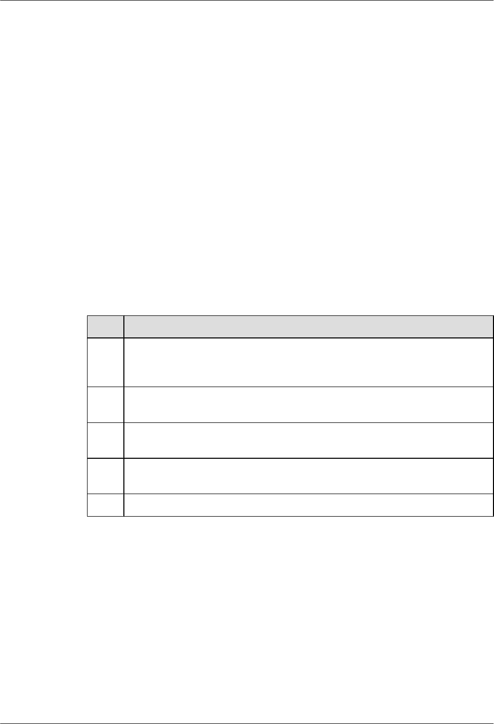
lImproving the reliability of the AC power supply system reduces the necessary capacity of
storage batteries. For small offices, increase the capacity of storage batteries if it is difficult
to enhance the reliability of the AC power supply system.
lThe total capacity of the high-frequency switching rectifier must satisfy the power of the
communication loading and battery charging. If there are 10 or fewer active rectifier
modules, configure one backup module. If there are more than 10 active modules, configure
one backup module for every 10 active modules.
lInstall storage batteries in two or more groups. The capacity is determined by the duration
for which the storage batteries must supply power. For most offices, the batteries should
be able to supply power for at least one hour.
5.3 Equipment Grounding Specifications
5.3.1 General Grounding Specifications
Table 5-16 shows the general grounding specifications.
Table 5-16 General grounding specifications
No. Description
1The working grounding and protection grounding, including the shielded grounding
and the lightning-proof grounding of the cable distribution frame should share the
same grounding conductor.
2 The cable trays, shells, metal ventilation pipes, metal doors and windows in the
equipment room should be grounded for protection.
3 The metal parts of the equipment which are electrically floating in normal conditions
should be grounded for protection.
4 The ground cable must be connected securely to the protection ground bar of the
equipment room.
5 Do not use other equipment as part of the ground cable or electrical connection.
5.3.2 Grounding Specifications for an Equipment Room
The grounding resistance of a comprehensive communication building should be less than or
equal to one ohm. The grounding resistance of an ordinary communication office should be less
than five ohms. The grounding resistance in an area where the earth resistance rate is high should
be less than 10 ohms.
5.3.3 Grounding Specifications for Devices
Table 5-17 shows the equipment grounding specifications.
Huawei AP8030DN & AP8130DN
Hardware Installation and Maintenance Guide 5 Appendix
Issue 03 (2015-05-18) Huawei Proprietary and Confidential
Copyright © Huawei Technologies Co., Ltd.
103

Table 5-17 Equipment Grounding Specifications
No. Description
1All communication devices and auxiliary devices (such as mobile base stations,
transmission and switching devices, power supply devices) in the equipment room
should be grounded for protection. Connect all protection grounding for various
devices jointly to a general ground bar, and then to the same protection ground bar
in the room together with the protection ground (PGND) of the device.
2 The PGND of the equipment is shorted to the copper protection ground bar provided
by the user. The short-circuiting cable used should be an alternating yellow and green
plastic insulating one with copper core, with cross-sectional area greater than 25 sq.
mm (0.039 sq. in.).
3 There are grounding terminals and grounding lugs at the lower part of the front door,
rear door and side panel of the cabinet, connected to the grounding terminals of the
cabinet framework through connection cables with cross-sectional area no less than
1.6 sq. mm (0.002 sq. in.).
4 Ensure that all metal components of the cabinet conduct well. No insulating coating
should be sprayed on the connection part of the metal components.
5 Connect the cabinets in the same row by fastening captive screws and gaskets on the
top of the cabinets. Do not spray any coating into a rectangular area measuring 30
mm x 50 mm (1.18 in. x 1.97 in.) around the connection hole for a captive bolt.
Measures to prevent rust and corrosion must be taken for this area. Zinc electroplating
with iridescent yellow chromate conversion coating should be applied to the gasket
and nut to ensure good electrical contact.
6 When combining cabinets of the same type, short-circuiting cables are required to
connect the ground busbars (if any) of the cabinets. The cross-sectional area of the
short-circuiting cable is 6 sq. mm (0.009 sq. in.) and is no more than 300 mm (11.8
in.) long. Connect the two ends of the short-circuiting cable to the ground busbar
terminals of neighboring cabinets and fix them firmly.
5.3.4 Grounding Specifications for Communications Power Supply
Table 5-18 shows the grounding specifications for communication power supplies.
Table 5-18 Grounding specifications for communication power supplies
No. Description
1The inlet for the AC power cable at the equipment room should be equipped with a
surge protection device (C-level) with a nominal discharge current no less than 20
kA.
2 The protection ground for the power supply and that for communication equipment
share the same grounding conductor. If the power supply and the equipment are in
the same equipment room, use the same protection ground bar for them if possible.
Huawei AP8030DN & AP8130DN
Hardware Installation and Maintenance Guide 5 Appendix
Issue 03 (2015-05-18) Huawei Proprietary and Confidential
Copyright © Huawei Technologies Co., Ltd.
104
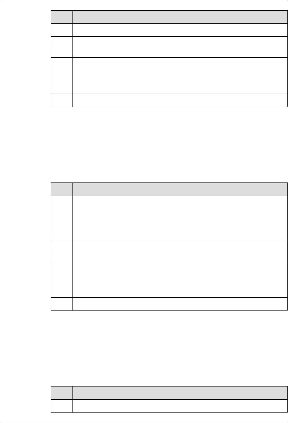
No. Description
3Use a surge protection circuit on the AC power interface.
4 The positive of the -48 V DC power supply or negative pole of the 24 V DC power
supply should be grounded at the output of the DC power supply.
5 The working ground and protection ground of the DC power supply equipment should
use the same grounding conductor with the protection ground of the switching
equipment. If the power supply and equipment are in the same equipment room, use
the same protection ground bar for them if possible.
6 Add surge protection on the DC power interface.
5.3.5 Grounding Specifications for Signal Cables
Grounding specifications for signal cables are shown in Table 5-19.
Table 5-19 Grounding specifications for signal cables
No. Description
1Equip the cable outdoors with a metal jacket, well grounded at both ends, or connect
the ends of the metal jacket to the protection ground bar of the equipment room. For
cables inside the equipment room, install surge protection devices at the interface to
the equipment. The PGND cable for the surge protection devices should be as short
as possible.
2 The incoming and outgoing signal cables to and from the office and unused wires
inside the cable should be grounded for protection.
3 The Tone & Data Access (TDA) cable must pass through the Main Distribution
Frame (MDF) with surge protective device (SPD) when going out of the office. The
cable's shield layer should be connected to the protection ground of the MDF. The
MDF should use the same grounding conductor with the cabinet.
4 The signal cables should not be routed overhead.
5.3.6 Specifications for Laying Out Grounding Cables
Table 5-20 shows the specifications for the ground cable.
Table 5-20 Specifications for laying out ground cables
No. Description
1The grounding wire should not run parallel to or twist around the signal cable.
Huawei AP8030DN & AP8130DN
Hardware Installation and Maintenance Guide 5 Appendix
Issue 03 (2015-05-18) Huawei Proprietary and Confidential
Copyright © Huawei Technologies Co., Ltd.
105

No. Description
2The ground cable cannot be routed overhead, but should be buried in the earth or
arranged indoors.
3 Do not connect two cables together to extend the PGND cable, or add any switch or
fuse.
4 The PGND cable should be an alternating yellow and green plastic insulating one
with copper core.
5 The neutral line of the AC power cable cannot be connected to the protection ground
of transmission and communication equipment in the equipment room.
6 The length of the PGND cable should not exceed 45 m (147.64 ft). The PGND cable
should be as short as possible.
5.4 Engineering Labels for Cables
An engineering label serves as an identifier for on-site installation and maintenance after the
installation. Labels on the cables facilitate correct and orderly connection of cables, and easy
maintenance after installation.
Specialized for power cables and signal cables, the types of engineering labels are as follows:
lThe signal cables include network cables, optical fibers, and user cables.
lThe power cables include the AC power cables and DC power cables.
NOTE
Fill in the label according to the user's requirements if the user needs an integrated description of the label.
Make a relevant statement in the self-check report.
5.4.1 Introduction to Labels
Label Materials
Features:
lThickness: 0.09 mm (0.004 in.)
lColor: chalk white
lMaterial: polyester (PET)
lAmbient temperature: -29°C (-20.2°F) to +149°C (300.2°F)
lCompatible with laser printing and handwriting with markers
lPass UL and CSA authentication
Huawei AP8030DN & AP8130DN
Hardware Installation and Maintenance Guide 5 Appendix
Issue 03 (2015-05-18) Huawei Proprietary and Confidential
Copyright © Huawei Technologies Co., Ltd.
106
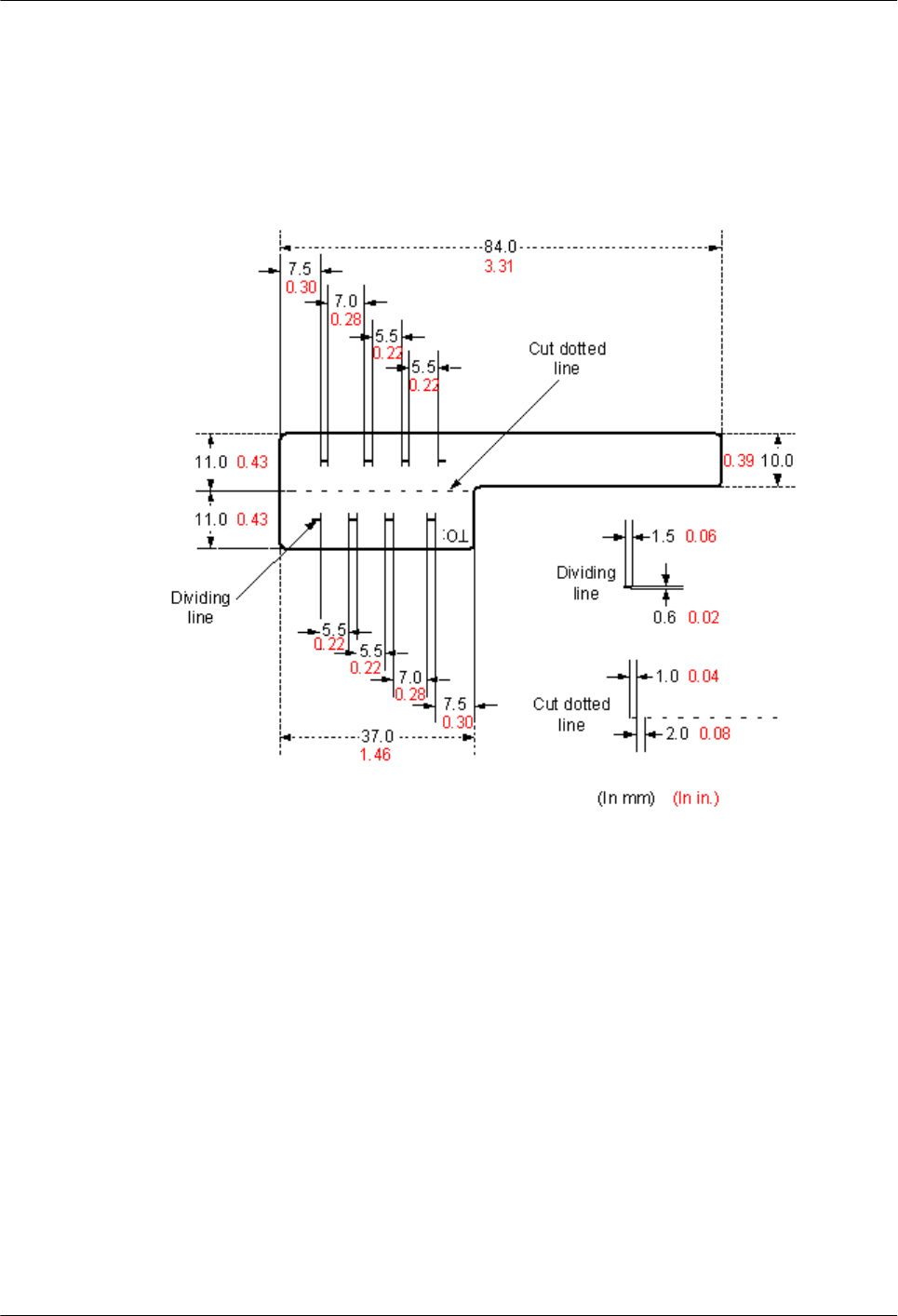
Type and Structure
Label for Signal Cables
The label for signal cables is L-shaped with fixed dimensions, as shown in Figure 5-81.
Figure 5-81 Label for signal cables
To specify more clearly the position of a cable, use the dividing lines on the label. For example,
there is a dividing line between the cabinet number and the chassis number, and another one
between the chassis number and the slot number. The dividing line is 1.5 mm x 0.6 mm (0.06
in. x 0.02 in.) with the color of Pantone 656c (light blue).
The cut dotted line helps to fold the label when affixed to the cable, and its size is 1 mm x 2 mm
(0.04 in. x 0.08 in.).
There is a mark "TO:" (upside down in the figure) at the lower right corner of the label. The
mark is used to identify the opposite end of the cable on which the label is affixed.
Power Cable Label
The label for power cables should be attached to the identification plate on the cable ties that
are attached to the cable. The identification plate has an embossed area 0.2 mm x 0.6 mm (0.008
in. x 0.02 in.) around (symmetric on both sides), and the area in the middle is for affixing the
label, as shown in Figure 5-82.
Huawei AP8030DN & AP8130DN
Hardware Installation and Maintenance Guide 5 Appendix
Issue 03 (2015-05-18) Huawei Proprietary and Confidential
Copyright © Huawei Technologies Co., Ltd.
107
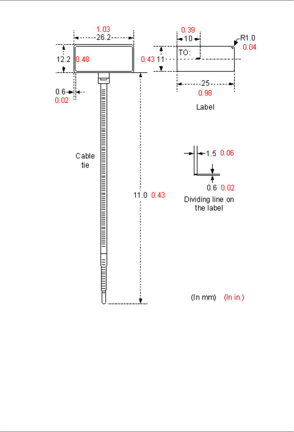
Figure 5-82 Power cable label
Label Printing
The contents can be printed or written on the labels. Printing is recommended for the sake of
high efficiency and eye-pleasant layout.
Template for Printing
Use a template to print labels. You can obtain the template from the Huawei local office.
The templates are made in Microsoft Word and the following requirements should be met:
Huawei AP8030DN & AP8130DN
Hardware Installation and Maintenance Guide 5 Appendix
Issue 03 (2015-05-18) Huawei Proprietary and Confidential
Copyright © Huawei Technologies Co., Ltd.
108

lWhen using the template, you can directly modify the contents of the template. The settings
of centered characters, direction, and fonts should not be changed.
lWhen there are too many characters to be filled in, zoom out the characters, but make sure
that the printouts are clear and legible.
Merging Cells in the Template
To merge two or more cells, do as follows:
1. Select Edit/Select All.
2. Select Format/Borders and Shading/Borders. Select Box tab and click OK.
3. Drag the mouse to select cells to be merged and select the Table/Merge Cells.
Requirements on the Printer
To print the labels, a laser jet printer must be used, although there is no restriction on the model
of the printer. Before printing the label, set up the page and try printing.
1. Try printing on ordinary paper with both sides blank. Place the blank paper over the whole
page of label paper, and check whether the page setup conforms to the label layout.
2. Make sure the printer properties, such as "paper size" and "direction", have been set
correctly.
lIf the printout conforms to the sheet of labels, print the labels on the label paper.
lIf the printout does not conform, adjust the page setup and try printing again until the
correct printout is produced.
The method of adjusting the page setup is as follows.
1. Select File/Page Setup.
2. Select Layout and set Header and Footer as 0.
3. Select the Margins tab page. Select Left for Gutter Position and adjust the values of Top,
Bottom, Left, and Right.
NOTE
If the warning prompt as shown in Figure 5-83 appears before printing, click Ignore to continue the
printing.
Figure 5-83 Warning prompt before printing
After the page setup has been made correctly, save it for future use. This page setup is only
necessary the first time you use the template to print the labels.
Huawei AP8030DN & AP8130DN
Hardware Installation and Maintenance Guide 5 Appendix
Issue 03 (2015-05-18) Huawei Proprietary and Confidential
Copyright © Huawei Technologies Co., Ltd.
109

Requirements for Feeding the Printer
The label paper consists of two layers and has undergone multiple processing procedures such
as printing and cutting. No matter what model of printer you use, feed in the labels one page at
a time. To avoid jamming the labels, never use the auto-feed mode.
Feed in the label paper in the correct direction to ensure that the text is printed in a correct
position.
Requirements for the Printed Label
Make sure that the printed labels satisfy the following requirements:
lAll the printouts must be on the label, and nothing should be printed on the backing layer
of the label page.
lContents in the cells should be aligned in the center. In a single-line printout, the dividing
lines and the mark "TO:" should not be covered by the printed characters.
lWhen the cells are merged and the printouts are made in multiple lines, avoid covering the
mark "TO:" when printing the texts. Use the space bar to move the text to the next line.
Writing Labels
Writing Tools
To make sure the printouts are clear and legible, use the black markers instead of ball-point pens
to write the labels.
In special cases, black ball-pens are allowed, although not recommended. Compared with ball-
point pens, water-proof markers are better. When writing with a ball-point pen, do not leave the
oil on the label, which may contaminate the label and blur the words.
NOTE
The delivered marker has two nibs. Make sure to use the smaller nib to write the labels.
Font
For the sake of easy recognition and good appearance, the font in handwriting should be as close
to a standard typeface (such as Times New Roman) as possible. Table 5-21 shows the standard
typeface.
Table 5-21 Standard typeface for handwriting
012345678
9 A B C D E F G H
I J K L M N O P Q
R S T U V W X Y Z
Determine the size of characters based on the number of letters or digits and ensure that the
characters are clear, distinct, and tidy.
Huawei AP8030DN & AP8130DN
Hardware Installation and Maintenance Guide 5 Appendix
Issue 03 (2015-05-18) Huawei Proprietary and Confidential
Copyright © Huawei Technologies Co., Ltd.
110
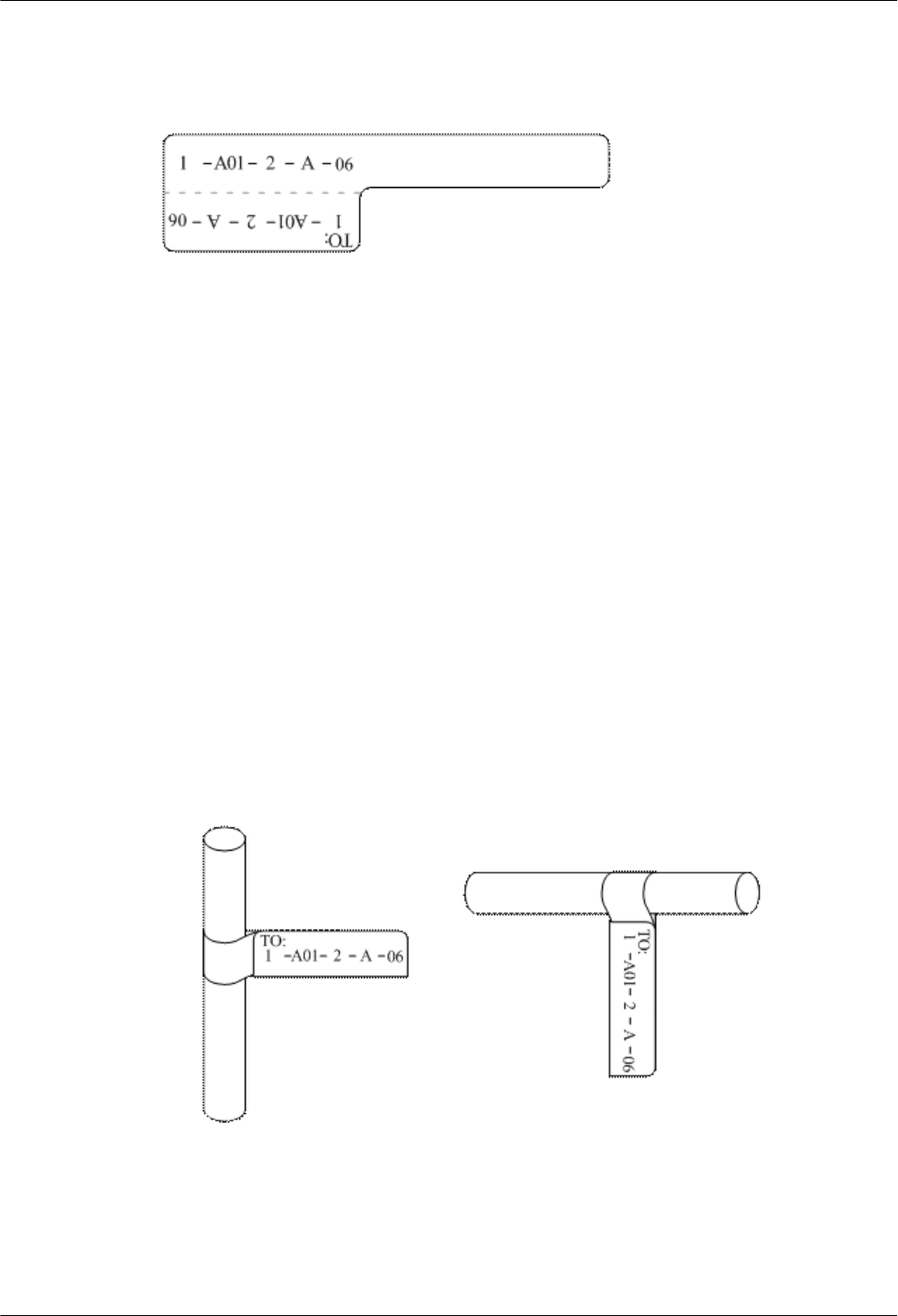
Writing direction: The direction is shown in Figure 5-84:
Figure 5-84 Writing direction of the characters on the label
Attaching Labels
After printing or writing the label, remove the label from the page and attach it to the signal
cable, or the identification plate of the power cable. The methods for attaching labels are
described in the following sections.
Label for Signal Cables
lChoose the place to attach labels.
The label is attached 2 cm (0.79 in.) from the connector on a signal cable. In special cases
(for example, to avoid cable bending or affecting other cables), other positions are allowed
to attach the labels. The rectangle part with characters is attached facing right or downward,
as shown in Figure 5-85. The details are as follows:
–The identification card is to the right of the cable in vertical cabling.
–The identification card should be downward when you lay out the cable horizontally.
Figure 5-85 Text area of the label
lProcedure for attaching labels
Figure 5-86 shows the methods and procedures for attaching labels.
Huawei AP8030DN & AP8130DN
Hardware Installation and Maintenance Guide 5 Appendix
Issue 03 (2015-05-18) Huawei Proprietary and Confidential
Copyright © Huawei Technologies Co., Ltd.
111
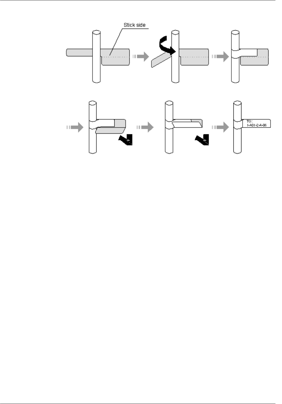
Figure 5-86 Label for signal cables
Power Cable Label
Remove the label from the backing page, and attach it to the identification plate on the cable tie.
The label should be attached to the rectangular flute on the identification plate, and attached to
only one side of the identification plate. The cable ties are bundled at 2 cm (0.79 in.) from the
connectors, and other positions are allowed in special circumstances.
Cable ties should be bound on both ends of a cable. After the bundling, the finished identification
plate should be on top of the cable in horizontal cabling, or on the right side of the cable in
vertical cabling, as shown in Figure 5-87. The details are as follows:
lThe identification card is to the right of the cable in vertical cabling.
lThe identification card is on the top of the cable in horizontal cabling. Make sure that the
label is facing out.
Huawei AP8030DN & AP8130DN
Hardware Installation and Maintenance Guide 5 Appendix
Issue 03 (2015-05-18) Huawei Proprietary and Confidential
Copyright © Huawei Technologies Co., Ltd.
112
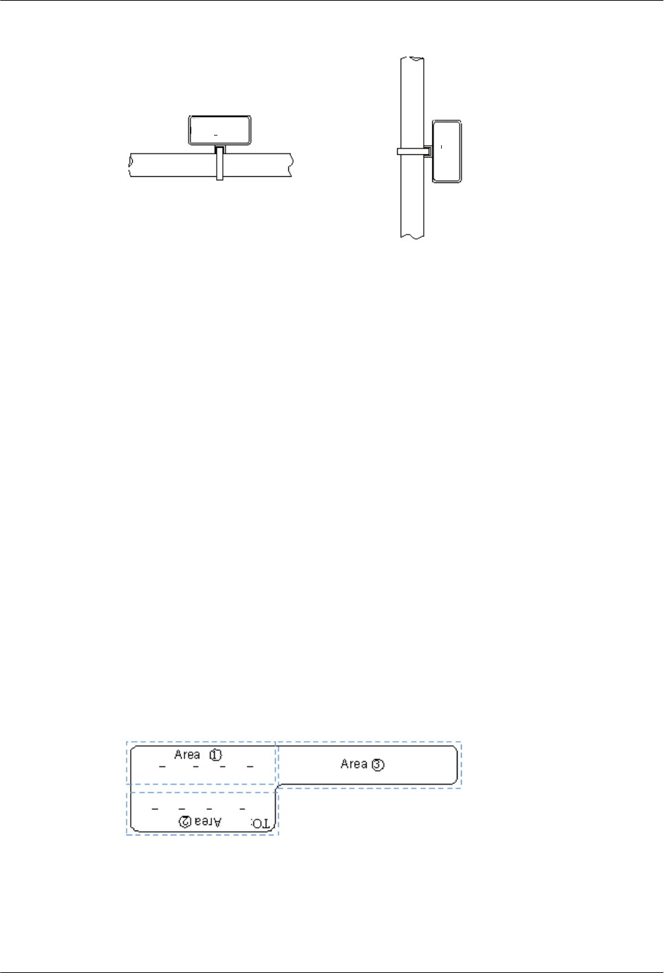
Figure 5-87 Binding the label for the power cable
The identification card is on the
top of the cable in horizontal
cabling.
The identification card is to
the right of the cable in
vertical cabling.
TO:
B03 -48V2
TO:
B03 -48V2
Cable
Cable
Contents of Engineering Labels
Contents of Labels for Power Cables
Labels for power cables are only affixed on one side of the identification plates. On the labels,
there is information (the part after the mark "TO:") about the location of the device on the other
end of the cable, like the location of control cabinet, distribution box or power socket.
Contents of Labels for Signal Cables
The two sides of the label affixed on the signal cable carry information about the location of the
ports connected to both ends of the cable. Figure 5-88 shows the information on both sides of
the labels affixed to the signal cables.
lArea 1 contains the location information of the local end of the cable.
lArea 2 (with the mark "TO:") contains the location information of the opposite end of the
cable.
lArea 3 has been folded up inside the label.
Figure 5-88 Printed parts on the label for signal cables
Seen from the cabling end of the equipment, the text part of the label is on the right side of the
cable. The side with "TO:" that is facing outside carries the location information of the opposite
end; and the other side carries the location information of the local end.
Huawei AP8030DN & AP8130DN
Hardware Installation and Maintenance Guide 5 Appendix
Issue 03 (2015-05-18) Huawei Proprietary and Confidential
Copyright © Huawei Technologies Co., Ltd.
113

Therefore, the information in Area 1 at one end is the same as the information in Area 2 at the
other end of the cable. In other words, the local information at one end is called the opposite
information at the other end.
Precautions for Using Engineering Labels
When using labels, pay attention to the following points:
lWhen printing, writing, or attaching labels, keep the labels clean.
lSince the label paper is made of moistureproof and waterproof material, ink-jet printers
and ink pens are forbidden for printing and writing labels.
lLabels should be attached tidily. New-type labels are L-shaped. If they are pasted at
incorrect locations or in wrong directions, the appearance of the device is affected.
lPower cable ties should be attached in the same positions on power cables, with
identification plates on the same side.
lThe positions of "up", "down", "left" or "right" are all based on the viewpoint of the
engineering person who works on the label.
5.4.2 Engineering Labels for Optical Fibers
These labels are affixed to the optical fibers that connect the optical interfaces on the boards in
a chassis, or on the device boxes. There are two types of labels for optical cables:
lOne is for the fiber that connects the optical interfaces on two devices.
lThe other is for the fiber that connects the device and the ODF.
Labels for the Optical Fibers Connecting Devices
Meaning of the Label
Table 5-22 lists information on both sides of the labels affixed to the optical fibers that connect
two devices.
Table 5-22 Information on labels affixed to the fiber between two devices
Content Meaning Example
MN-B-C-D-
R/T
MN: cabinet
number
M: The cabinet rows from front to back are numbered
from A to Z.
N: The cabinet columns from left to right are numbered
from 01 to 99.
For example, A01 is the cabinet in Row A and Column
01.
B: chassis
number
Numbered in bottom-up order with two digits, for
example, 01.
C: physical slot
number
Numbered in the top-down and left-right order starting
from 01. For example, 01 is the slot with number 1.
Huawei AP8030DN & AP8130DN
Hardware Installation and Maintenance Guide 5 Appendix
Issue 03 (2015-05-18) Huawei Proprietary and Confidential
Copyright © Huawei Technologies Co., Ltd.
114
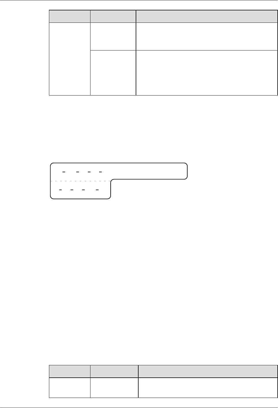
Content Meaning Example
D: optical
interface
number.
Numbered in a top-bottom and left-right order, consistent
with the port sequence number on the device.
R: Receiving
interface
T: optical
transmitting
interface
-
Example of the Label
Figure 5-89 shows the label on the cable.
Figure 5-89 Example of the label on the optical fiber between two devices
A01 R
TO:
01 05 01
G01 T
01 01 01
The meaning of the labels is listed in Figure 5-89.
l"A01-01-05-01-R" indicates that the local end of the optical fiber is connected with the
optical receiving interface 01 on slot 5, chassis 01 in the cabinet on row A, column 01 in
the machine room.
l"G01-01-01-01-T" indicates that the opposite end of the optical fiber is connected with
Optical Transmitting Interface 01 on Slot 01, Chassis 01 in the cabinet on Row G, Column
01 in the machine room.
Labels for the Optical Fibers Connecting the Device and an ODF
Meaning of the Labels
Table 5-23 shows the information on both sides of the labels attached to the optical fiber that
connects the device and the ODF.
Table 5-23 Information on labels affixed to the fiber between the device and the ODF
Content Meaning Example
MN-B-C-D-
R/T
MN: cabinet
number
For example, A01.
Huawei AP8030DN & AP8130DN
Hardware Installation and Maintenance Guide 5 Appendix
Issue 03 (2015-05-18) Huawei Proprietary and Confidential
Copyright © Huawei Technologies Co., Ltd.
115
Content Meaning Example
B: chassis
number
Numbered in bottom-up order with two digits, for
example, 01.
C: physical slot
number
Numbered in the top-down and left-right order starting
from 01. For example, 01 is the slot with number 1.
D: optical
interface
number.
Numbered in a top-down and left-right order, consistent
with the port sequence number on the device.
R: Optical
receiving
interface
T: optical
transmitting
interface
-
ODF-MN-B-
C-R/T
MN: row number
and column
number of an
ODF
M: The cabinet rows from front to back are numbered
from A to Z.
N: The cabinet columns from left to right are numbered
from 01 to 99.
For example, G01 is the ODF of Row G and Column 01.
B: row number of
the terminal
device
Range from 01 to 99, for example, 01-01.
C: column
number of the
terminal device
R: Optical
receiving
interface
T: optical
transmitting
interface
-
Example of the Label
Figure 5-90 shows the label on the cable.
Figure 5-90 Example of the label on the optical fiber between the device and the ODF
ODF R
TO:
G01 01 01
A01 R
01 05 01
Huawei AP8030DN & AP8130DN
Hardware Installation and Maintenance Guide 5 Appendix
Issue 03 (2015-05-18) Huawei Proprietary and Confidential
Copyright © Huawei Technologies Co., Ltd.
116

Meaning of the label in Figure 5-90
l"ODF-G01-01-01-R" indicates that the local end of the optical fiber is connected to the
optical receiving terminal on row 01, column 01 of the ODF in row G, column 01 in the
machine room.
l"A01-01-05-01-R" indicates that the opposite end of the optical fiber is connected to Optical
Receiving Interface 1 on Slot 05, chassis 01 in the cabinet on Row A, Column 01 in the
machine room.
5.4.3 Engineering Labels for Network Cables
Applicable Ranges
The labels can be applied to Ethernet cables.
Label Content
Table 5-24 shows the information on both sides of the labels affixed to Ethernet cables.
You can also decide the label content according to the actual environment. If the device is not
installed in the cabinet, for example, you can remove the cabinet number.
Table 5-24 Information on the Ethernet cables
Content Meaning Example
MN-B-C-D MN: cabinet
number
For example, A01 is the first cabinet in row A.
B: chassis number Numbered in the bottom-up order with two digits, for
example, 01.
C: physical slot
number
Numbered with two digits in top-down and left-right
order. For example, 01.
D: network port
number
Numbered in the top-down and left-right orders. For
example, 01.
MN-Z MN: cabinet
number
For example, B02 is the second cabinet in Row B.
Z: Location
number
Fill in the location number of the terminal device on
site. If the cable is connected to a device in a cabinet,
the serial numbers of the cabinet, the chassis, and the
Ethernet interface of the device should be specified.
For example, B02-03-12. If the cable is connected to
the Network Management Station (NMS), the
specific location of the NMS should be given.
Huawei AP8030DN & AP8130DN
Hardware Installation and Maintenance Guide 5 Appendix
Issue 03 (2015-05-18) Huawei Proprietary and Confidential
Copyright © Huawei Technologies Co., Ltd.
117
The contents of the labels for network cables connecting hubs and devices or agents and the
network cables for other purposes should be specified according to actual connections. The
details are as follows:
lFor a network cable connecting a hub and device, the label on the hub end should indicate
the numbers of the chassis and cabinet where the hub resides, and the serial number on the
hub. The label on the device end should indicate the number of the chassis and cabinet
where the device is located. If the device is a stand-alone device, the specific position of
the device should be provided.
lFor a network cable connecting a hub and an agent or terminal, the label on the agent or
terminal end should contain the serial number of the network interface. The definitions of
the cabinet number and chassis number are the same as those described in Table 5-24.
lIf the hub is a stand-alone device without cabinet or chassis, the label should contain specific
location information that identifies the hub.
The serial number on the hub, the network interface number of the agent or terminal, and the
location of the stand-alone device should be specified according to actual connections.
Label Example
Figure 5-91 shows the label on the cable.
Figure 5-91 Example of the label on network cables
A01
TO:
03 01 01
B02 03 01
Meaning of the label in Figure 5-91.
l"A01-03-01-01" indicates that one end of the network cable is connected to network
interface 01 of slot 01, chassis 03 of the cabinet on row A, column 01 in the equipment
room.
l"B02-03-01" indicates that another end of the network cable is connected to network
interface 01, chassis 03 of the cabinet on row B, column 02 in the equipment room. No slot
number is given.
5.4.4 Engineering Labels for User Cables
Attach labels to both ends of the cable to indicate the locations of the cable on the device and
MDF.
Meaning of the Engineering Labels for User Cables
Table 5-25 shows the contents of the labels.
Huawei AP8030DN & AP8130DN
Hardware Installation and Maintenance Guide 5 Appendix
Issue 03 (2015-05-18) Huawei Proprietary and Confidential
Copyright © Huawei Technologies Co., Ltd.
118
Table 5-25 Contents of the engineering labels for user cables
Content Meaning Example
MN-B-C-D MN: cabinet
number
For example, A01 is the first cabinet in row A.
B: frame number Numbered in the bottom-up order with two digits, for
example, 03.
C: physical slot
number
Numbered with two digits in the top-down and left-
right order. For example, 01.
D: cable number Numbered with two digits in the top-down and left-
right order. For example, 01.
MDF-MN-B-C MN: row number
and column
number of the
MDF
M: The rows of cabinets from front to back are
numbered from A to Z. N: The columns of cabinets
from left to right are numbered from 01 to 99. For
example, G01 is the MDF of row G and column 01.
B: row number of
the terminal device
Ranges from 01 to 99, for example, 01-01.
C: column number
of the terminal
device
Example of the Label
Figure 5-92 shows an example.
Figure 5-92 Example of labels for user cables
A01
TO:
03 01 01
MDF G01 01 01
The meaning of the label in Figure 5-92 is as follows:
l"A01-03-01-01" indicates that the local end of the user cable is connected to port 1 of on
slot 1, chassis 03 of the cabinet on row A, column 01 in the equipment room.
l"MDF-G01-01-01" indicates that the opposite end of the user cable is connected to the
terminal on row 01, column 01 of the MDF in row G, column 01 in the equipment room.
5.4.5 Engineering Labels for Power Cables
Huawei AP8030DN & AP8130DN
Hardware Installation and Maintenance Guide 5 Appendix
Issue 03 (2015-05-18) Huawei Proprietary and Confidential
Copyright © Huawei Technologies Co., Ltd.
119
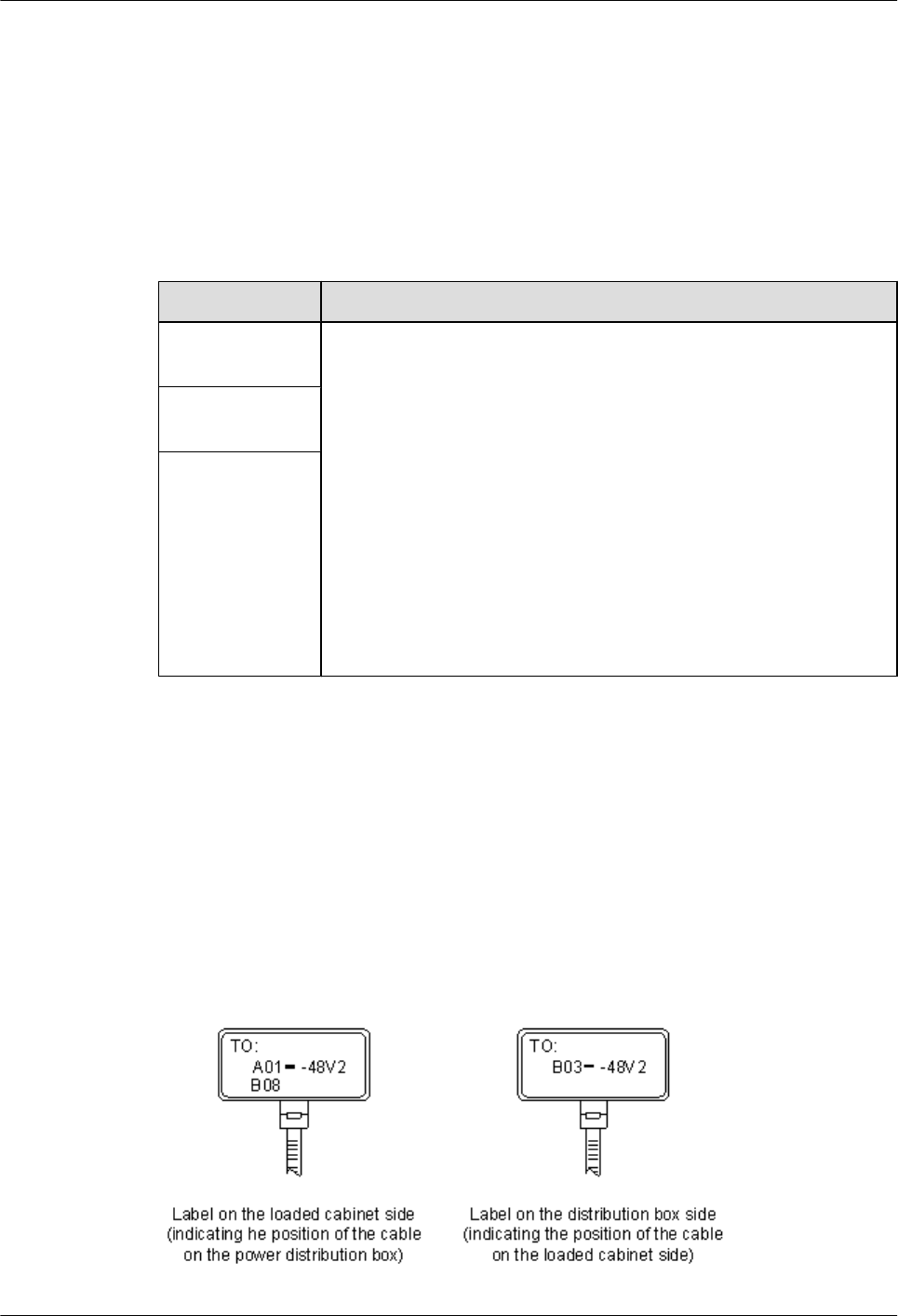
Engineering Labels for DC Power Cables
The labels are affixed to the DC power cables that provide power supply for cabinets, including
the -48 V, PGND, and BGND cables. Here, the DC power cables also include power cables and
PGND cables.
The labels for DC power cables are affixed to one side of the identification plates on cable ties.
For details of the labels, see Table 5-26.
Table 5-26 Contents of the label
Content Meaning
MN(BC)-
B--48Vn
MN(BC): BC is written right under MN.
B: chassis number, numbered in the bottom-up order with two digits, for
example, 01.
N: power socket number, numbered as 1 to 3 in the bottom-up and left-
to-right orders.
On the loaded cabinet side, only MN is used to identify the cabinet.
On the power cabinet side, MN identifies the row and column number
of the power distribution equipment like a control cabinet and
distribution box, and BC identifies the row and column number of the
-48 V connector. If there is no row number or column number, or the
connector can be identified without them, BC can be omitted. It is
unnecessary for BGND and PGND to identify the row and column
number.
MN(BC)-B-
BGND
MN(BC)-B-
PGND
The label only carries location information about the destination direction of the power cable
while information of the local end is not necessary. That is, the label only carries location
information about the opposite equipment, the control cabinet, or the distribution box. Table
5-26 lists the information on two -48 V power supplies on the label. The information on other
DC voltages, such as 24 V and 60 V should be given in similar methods.
Make sure that labels are affixed in the correction direction. That is, after the cable ties are
bundled onto the cable, the identification plates with the labels should face up, and the text on
the labels in the same cabinet should be in the same direction. For details, see Figure 5-93.
Figure 5-93 Example of the labels for DC power cables
Huawei AP8030DN & AP8130DN
Hardware Installation and Maintenance Guide 5 Appendix
Issue 03 (2015-05-18) Huawei Proprietary and Confidential
Copyright © Huawei Technologies Co., Ltd.
120

The meaning of the label in Figure 5-93 is as follows:
lOn the loaded cabinet side, the label "A01/B08--48V2" on the cable indicates that the cable
is -48 V DC supply, which is from the eighth connector on row B of -48 V bus bar in the
cabinet on row A, and column 1 in the equipment room.
lOn the distribution box side, the label "B03--48V2" indicates that the cable is -48 V DC
supply, connected to DC power socket 2 on row B, column 03 in the equipment room.
NOTE
In the power distribution box or the first power cabinet of a row in a transmission equipment room, every
terminal block on the -48 V connector bar has a numeric identification. For example, in the above label of
"A01/B08--48V2", "08" (or sometimes "8") is the numeric identification of the terminal block.
PGND and BGND are two copper bars, on which the terminal blocks are short-circuited,
therefore which terminal is connected makes no difference. It is only necessary to give the row
and column of the power distribution box, instead of giving the specific serial number of the
terminal block on the copper bar. For example, if the label on the loaded cabinet side is "A01-
BGND", it means that the power cable is a BGND that connects BGND copper bar in the power
distribution box on Row A, Column 01 in the machine room. Information on the labels for PGND
cables should be given in a similar way.
Engineering Labels for AC Power Cables
The labels are affixed to both ends of an AC power cable that provides AC power supply to
cabinets, including 110/220 V, PGND, and BGND cables. The 110/220 V AC cables and related
PGND and BGND cables are covered with an insulating sheath, so the labels need to contain
only the word "AC" and the cabinet numbers.
The labels for AC power cables are affixed to one side of the identification plates on cable ties.
For details, see Table 5-27.
Table 5-27 Label content
Content Meaning
MN-(B)-ACn MN: serial number of the cabinet or the socket where the power is led in
B: chassis number, numbered in the bottom-up order with two digits, for
example, 01.
n: power port number, numbered as 1 to 3 in bottom-up and left-to-right
order.
Serial number of the socket where the power is led in: the location of the
socket is marked according to the actual situation. If the sockets can be
identified by row numbers and column numbers, they can be numbered
following the same rule for the cabinets. If the sockets cannot be identified
by rows and columns, specify the detailed locations to avoid confusion
with other sockets.
The label only carries location information about the opposite equipment and the power socket;
information about the local end is not necessary.
Huawei AP8030DN & AP8130DN
Hardware Installation and Maintenance Guide 5 Appendix
Issue 03 (2015-05-18) Huawei Proprietary and Confidential
Copyright © Huawei Technologies Co., Ltd.
121
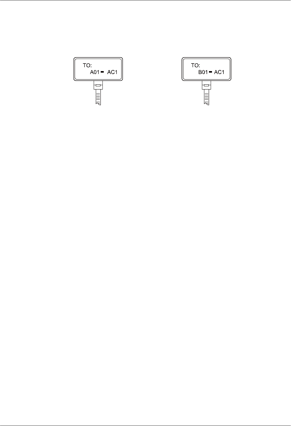
Make sure that labels are affixed in correct direction. That is, after the cable ties are bundled
onto the cable, the identification plates with the labels should face up, and the text on the labels
in the same cabinet should be in the same direction, as shown in Figure 5-94.
Figure 5-94 Labels for AC power cables
Label on the loaded cabinet side
(indicating the position of the cable
on the power distribution box)
Label on the distribution box side
(indicating the position of the cable
on the loaded cabinet side)
Meaning of the label in Figure 5-94.
lOn the equipment cabinet side, the label marked with "A01-AC1" indicates that the power
cable is connected to the first AC power socket of Row A and Column 01 in the equipment
room.
lOn the power socket side, the label marked with "B01-AC1" indicates that the power cable
is connected to the first AC power socket in the cabinet of Row B and Column 01 in the
equipment room.
5.5 Guide to Using Optical Modules
Common Faults of an Optical Module
1. An optical module is not completely installed in position.
If the optical module is not completely installed in position and the latch boss is not secured,
the device cannot identify the optical module. After the optical module works for a long
time, it will be ejected under external stress.
2. The optical receptacle on an optical module is contaminated.
If an optical module is not cleaned or protected properly, contaminants may accumulate on
the fiber pin in the optical module. As a result, the coupling efficiency is reduced, optical
signals are cut off, or even worse, the surface of the fiber pin is damaged permanently.
3. An optical module is burnt.
If large-power optical signals (caused by the OTDR or self-loop test) are transmitted
through an optical module that is used for long-distance transmission but no optical
attenuator is used, the optical power will exceed the overload power of the APD pipe. Then
the optical module is burnt.
The preceding faults lead to temporary or long-term cut-off of optical signals; or even cause
permanent damages to the optical module, affecting communication services.
Huawei AP8030DN & AP8130DN
Hardware Installation and Maintenance Guide 5 Appendix
Issue 03 (2015-05-18) Huawei Proprietary and Confidential
Copyright © Huawei Technologies Co., Ltd.
122
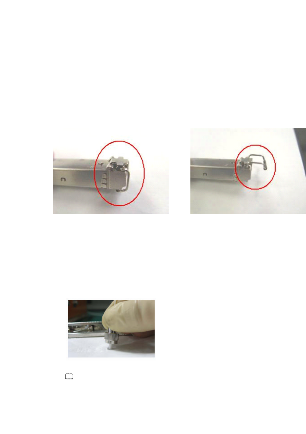
Measures to Prevent Loosened Optical Module
1. When installing an optical module, insert it into position. If you hear a click or feel a slight
shake, it indicates that the latch boss is secured.
If the latch boss is not secured, the gold finger of the optical module is not in good contact
with the connector on the board. In this case, the link may be connected but optical signals
will be cut off or the optical module will be loosened when the optical module is shook or
crashed.
2. Figure 5-95 shows the release handle on an optical module when it is open and closed.
When inserting the optical module, make sure that the release handle is closed. At this time,
the latch boss locks the optical module. After the optical module is inserted, try pulling it
out to see if it is installed in position. If the optical module cannot be pulled out, it is secured.
Figure 5-95 State of the release handle
Close the release handle Open the release handle
Measures to Prevent Receptacle Contamination
1. Cleaning tissues must be prepared on site. You need to clean the optical connector before
inserting it in the receptacle. This protects the receptacle against the contamination on the
surface of the optical connector.
Figure 5-96 Cleaning optical fibers with special cleaning tissues
NOTE
Place at least three cleaning tissues on the work bench. As shown in Figure 5-96, wipe the end of an
optical connector from left to right or from right to left on a cleaning tissue, and then move the
connector end to the unused part of the cleaning tissue to continue.
2. Cover an unused optical module with a protective cap to prevent dust, as shown in Figure
5-97.
Huawei AP8030DN & AP8130DN
Hardware Installation and Maintenance Guide 5 Appendix
Issue 03 (2015-05-18) Huawei Proprietary and Confidential
Copyright © Huawei Technologies Co., Ltd.
123
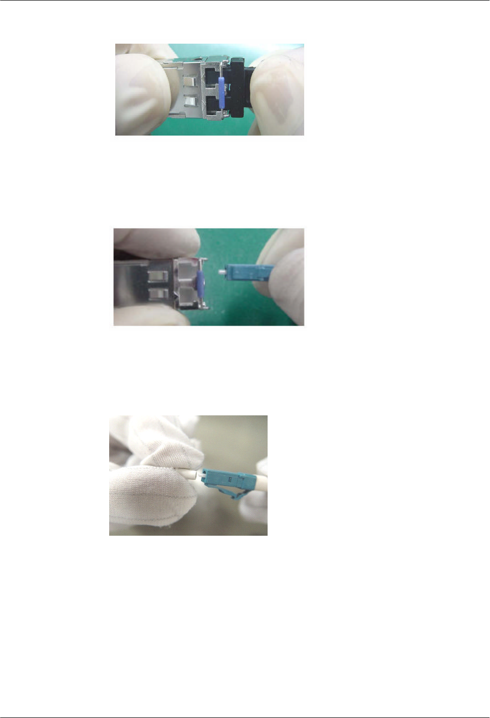
Figure 5-97 Installing a protective cap
If no protective cap is available, use fibers to protect the optical module, as shown in Figure
5-98.
Figure 5-98 Using fibers to protect an optical module
3. Cover unused optical connectors with protective caps, as shown in Figure 5-99, and then
lay out fibers on the fiber rack or coil them in a fiber management tray to prevent fibers
from being squeezed.
Figure 5-99 Installing a protective cap on a fiber
4. If a receptacle or an optical connector has not been used for a long time and is not covered
with a protective cap, you need to clean it before using it. Clean a receptacle with a cotton
swab, as shown in Figure 5-100. Clean an optical connector with cleaning tissues.
Huawei AP8030DN & AP8130DN
Hardware Installation and Maintenance Guide 5 Appendix
Issue 03 (2015-05-18) Huawei Proprietary and Confidential
Copyright © Huawei Technologies Co., Ltd.
124
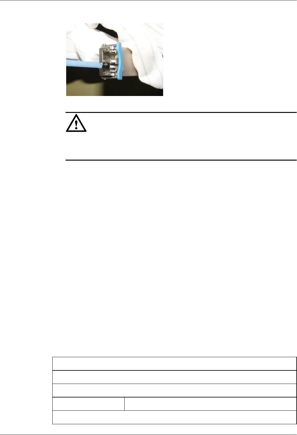
Figure 5-100 Cleaning a receptacle with a cotton swab
NOTICE
When cleaning a receptacle, insert the cotton swab and turn it slowly in the receptacle. Do
not use too much strength because the receptacle may be damaged.
5. If optical signals are lost during the operation of a device, use the preceding method to
clean the receptacle or the optical connector. In this manner, the possibility of contamination
can be excluded.
Measures to Prevent an Optical Module from Being Burnt
1. Before using an optical time-domain reflectometer (OTDR) to test the connectivity or the
attenuation of optical signals, disconnect the optical fibers from the optical module.
Otherwise, the optical module will be burnt.
2. When performing a self-loop test, use an optical attenuator. Do not loosen the optical
connector instead of the optical attenuator.
Precautions
1. The optical connector should be vertically inserted in the receptacle to avoid damages to
the receptacle.
2. Fibers must be inserted into optical modules of the corresponding type. That is, multimode
fibers must be inserted into multimode optical modules, and single mode fibers must be
inserted into single mode optical modules. If a fiber is inserted into an optical module of a
different mode, faults may occur. For example, optical signals will be lost.
5.6 Fault Tag
*Customer name:
Address:
Contact person:
Tel.: Fax:
Category*: □ RMA □ Return □ Analysis
Huawei AP8030DN & AP8130DN
Hardware Installation and Maintenance Guide 5 Appendix
Issue 03 (2015-05-18) Huawei Proprietary and Confidential
Copyright © Huawei Technologies Co., Ltd.
125

BOM
Code
Product
Description
Bar
Code*
Fault
Occurring
Date*
Description
of the Fault
Phenomena*
Category
No.*
Software
Version*
Reasons for Repairing (Category No.):
Category No. includes the following eight types:
F001 - Wear out damaged (◊ In warranty Period ◊ Out of warranty period)
F002 - Deployment damaged
F003 - Intransit damaged
F004 - Version upgrade
F005 - Batch replace
F007 - Overdue spare parts inspecting
F008 - Others
F011 - Running circumstance change
Note:
lFor optical interface cards returned, the optical interfaces should be covered with
protection caps.
lIn general, the analysis card will not be returned to you. If you have any special
requirements, please contact Huawei.
lOne Fault Tag should be adapted in one return category, such as RMA/Return/Analysis.
lThe items marked with "*" are the mandatory fields that you must fill in.
Huawei AP8030DN & AP8130DN
Hardware Installation and Maintenance Guide 5 Appendix
Issue 03 (2015-05-18) Huawei Proprietary and Confidential
Copyright © Huawei Technologies Co., Ltd.
126