Huawei Technologies BTS3601C-1900 CDMA Base Station User Manual 1
Huawei Technologies Co.,Ltd CDMA Base Station 1
Contents
- 1. User Manual 1
- 2. User Manual 2
- 3. User Manual 3
- 4. User Manual 4
User Manual 1

Installation Manual
iSiteC BTS3601C CDMA Base Station Hardware Installation
Table of Contents
i
Table of Contents
1 Installation Preparations....................................................................................................1-1
1.1 Personnel Requirements ............................................................................................1-1
1.1.1 Basic Requirements.........................................................................................1-1
1.1.2 Requirements for Antenna & Feeder Installation Personnel.................................1-1
1.2 Technical Documents Preparation ..............................................................................1-2
1.3 Installation Tools & Instruments Preparation ................................................................1-3
1.4 Installation Environment Check...................................................................................1-6
1.5 Project Plan and Kickoff Coordination .........................................................................1-6
1.5.1 Project Plan .....................................................................................................1-6
1.5.2 Kickoff Coordination .........................................................................................1-7
1.6 Unpacking Check.......................................................................................................1-7
1.6.1 Packing List Collation .......................................................................................1-7
1.6.2 Unpacking Inspection on Wooden Cases...........................................................1-8
1.6.3 Unpacking Inspection on Cartons......................................................................1-9
1.6.4 Acceptance and Handover..............................................................................1-11
2 Installing Cabinet Hardware...............................................................................................2-1
2.1 Hardware Components ..............................................................................................2-1
2.1.1 Component Structure .......................................................................................2-1
2.1.2 Introduction of Hardware Major Equipment ........................................................2-2
2.1.3 Introduction of Hardware Auxiliary Equipment....................................................2-2
2.1.4 Installation Mode..............................................................................................2-3
2.1.5 Installation Flow...............................................................................................2-3
2.2 Installation Planning...................................................................................................2-5
2.2.1 Example of Indoor Wall Installation....................................................................2-5
2.2.2 Example of Indoor Plinth Installation..................................................................2-6
2.2.3 Example of Concrete Pole Installation ...............................................................2-6
2.2.4 Example of Metal Mast Installation on Building-top .............................................2-9
2.2.5 Example of Tower Installation .........................................................................2-11
2.3 Installing Major Equipment .......................................................................................2-13
2.3.1 Installation Flow.............................................................................................2-13
2.3.2 Installing BTS3601C on the Wall .....................................................................2-14
2.3.3 Installing BTS3601C on Plinth.........................................................................2-18
2.3.4 Installing BTS3601C on Metal Mast and Concrete Pole ....................................2-21
2.3.5 Installing Modules ..........................................................................................2-23
2.3.6 Installing Cables ............................................................................................2-25
2.3.7 Installing Shell ...............................................................................................2-31
2.3.8 Installing Sun-shading Cover ..........................................................................2-32

Installation Manual
iSiteC BTS3601C CDMA Base Station Hardware Installation
Table of Contents
ii
2.4 Installing Auxiliary Equipment ...................................................................................2-32
2.4.1 Installing IAFB...............................................................................................2-33
2.4.2 Installing AC Lightning Protection Box.............................................................2-34
2.4.3 Installing UPS ................................................................................................2-40
2.4.4 Installing IABB ...............................................................................................2-40
2.5 Installing Cables ......................................................................................................2-48
2.5.1 Cable Connection Requirements.....................................................................2-49
2.5.2 Networking of AC Lightning Protection Box......................................................2-53
2.5.3 Networking of IAFB ........................................................................................2-56
2.5.4 Networking of Inverter ....................................................................................2-66
3 Installing RF Antenna and Feeder System.........................................................................3-1
3.1 Installation Flow.........................................................................................................3-1
3.2 Installing Antenna Accessories ...................................................................................3-3
3.2.1 Installing Omni Antenna Accessories.................................................................3-3
3.2.2 Installing Directional Antenna Accessories.........................................................3-4
3.3 Installing Grounding Bar .............................................................................................3-6
3.4 Installing Antenna Support..........................................................................................3-8
3.4.1 Installing Support on Tower Platform.................................................................3-8
3.4.2 Installing Support on Building-top ....................................................................3-10
3.5 Installing Antenna ....................................................................................................3-16
3.5.1 Antenna Facade ............................................................................................3-16
3.5.2 Hoisting Antenna ...........................................................................................3-16
3.5.3 Installing Omni Antenna .................................................................................3-16
3.5.4 Installing Directional Antenna..........................................................................3-19
3.6 Installing Feeder Window .........................................................................................3-23
3.6.1 About Feeder Window....................................................................................3-23
3.6.2 Installing Feeder Window ...............................................................................3-24
3.7 Installing Feeders ....................................................................................................3-25
3.7.1 Cutting Feeder ...............................................................................................3-25
3.7.2 Hoisting Feeder .............................................................................................3-26
3.7.3 Routing Feeder ..............................................................................................3-27
3.7.4 Affixing Feeder Labels....................................................................................3-28
3.7.5 Grounding Feeders ........................................................................................3-28
3.7.6 Leading Feeder into Equipment Room.............................................................3-30
3.7.7 Connecting Feeder and BTS...........................................................................3-31
3.8 System Testing........................................................................................................3-32
4 Installing Satellite Synchronization Antenna and Feeder System......................................4-1
4.1 Installing GPS Antenna and Feeder System................................................................4-1
4.2 Installing GPS Antenna ..............................................................................................4-2
4.2.1 Requirements for Installation Position................................................................4-2
4.2.2 Installing GPS Antenna Support........................................................................4-3
4.2.3 Installing Antenna ............................................................................................4-7

Installation Manual
iSiteC BTS3601C CDMA Base Station Hardware Installation
Table of Contents
iii
4.3 Installing GPS Feeder ................................................................................................4-8
4.3.1 Routing Feeder ................................................................................................4-8
4.3.2 Installing Lightning Arrester ..............................................................................4-9
4.3.3 Grounding Requirement .................................................................................4-11
4.3.4 Feeder Label .................................................................................................4-13
5 Installation Check ..............................................................................................................5-1
5.1 Overall Check............................................................................................................5-1
5.1.1 Checking Equipment Installation .......................................................................5-1
5.1.2 Checking Cable Connection..............................................................................5-1
5.1.3 Checking Lightning Protection Grounding..........................................................5-1
5.2 Power-on Check........................................................................................................5-3
5.3 Checking Environment Condition ................................................................................5-3
5.4 System Commissioning..............................................................................................5-3
A Installing IAFB.................................................................................................................. A-1
A.1 Installation Flow ....................................................................................................... A-1
A.2 Wall Installation ........................................................................................................ A-1
A.3 Metal Mast Installation .............................................................................................. A-4
A.4 Pole Installation........................................................................................................ A-5
A.5 Installation Check..................................................................................................... A-6
B Requirements for Antenna Isolation ................................................................................B-1
C Making Connectors..........................................................................................................C-1
C.1 Overview.................................................................................................................C-1
C.2 Making 7/16 DIN Connector and N Connector for Jumper ...........................................C-1
C.3 Making 7/16 DIN Connector and N Connector for 7/8 Feeder ......................................C-5
D Preparing Grounding Clips ..............................................................................................D-1
D.1 Overview.................................................................................................................D-1
D.2 Preparation Process.................................................................................................D-1

Installation Manual
iSiteC BTS3601C CDMA Base Station Table of Contents
i
Table of Contents
1 Installation Preparations............................................................................................................................ 1-1
1.1 Personnel Requirements................................................................................................................... 1-1
1.1.1 Basic Requirements............................................................................................................... 1-1
1.1.2 Requirements for Antenna & Feeder Installation Personnel ........................................ 1-1
1.2 Technical Documents Preparation.................................................................................................. 1-2
1.3 Installation Tools & Instruments Preparation................................................................................ 1-3
1.4 Installation Environment Check....................................................................................................... 1-6
1.5 Project Plan and Kickoff Coordination ........................................................................................... 1-6
1.5.1 Project Plan.............................................................................................................................. 1-6
1.5.2 Kickoff Coordination............................................................................................................... 1-7
1.6 Unpacking Check................................................................................................................................ 1-7
1.6.1 Packing List Collation ............................................................................................................ 1-7
1.6.2 Unpacking Inspection on Wooden Cases......................................................................... 1-8
1.6.3 Unpacking Inspection on Cartons....................................................................................... 1-9
1.6.4 Acceptance and Handover .................................................................................................1-11

Installation Manual
iSiteC BTS3601C CDMA Base Station
Hardware Installation
1 Installation Preparations
1-1
1 Installation Preparations
1.1 Personnel Requirements
1.1.1 Basic Requirements
If the project is cooperated with other parties, engineers from cooperation parties shall
play the key role in installation, engineers from the user shall provide necessary
assistance, and the engineers from the vendor shall supervise the whole installation
process.
If the project is not cooperated with other parties, engineers from the vendor shall play
the key role in installation, and engineers from the user shall provide assistance.
Engineers from the cooperation party shall be strictly trained and examined by the
vendor. Only after they have mastered the installation and testing methods, and
obtained the qualification certificates, can they implement the installation and
commissioning under the supervision of vendor engineers.
Engineers from the user shall receive some training given by the vendor to master the
installation and construction methods prior to the installation.
1.1.2 Requirements for Antenna & Feeder Installation Personnel
The antenna & feeder system is normally installed by the antenna & feeder installation
personnel under the supervision of the project supervisor. The number of installation
personnel should be determined according to installation environment.
Project supervisor:
l Should be familiar with the materials, tools and methods involved in the antenna &
feeder installation.
l Should have a strong consciousness of safety, organize the installation personnel
and coordinate their work on the principle of "Safety First", especially for the job on
tower.
l Should fill in the engineering data faithfully, e.g., antenna pitch angle, antenna
azimuth angle and number of feeders, etc.
Personnel for installation on the tower:
l Should obtain the certificates for the relevant work through relevant training;
Installation Manual
iSiteC BTS3601C CDMA Base Station
Hardware Installation
1 Installation Preparations
1-2
l Should be in good health, free of alcohol and have paid for personal safety
insurance;
l Should follow the operating requirements for safety appliances and wear safety
belts;
l Should not wear loose clothes or slipped shoes. And they must take with them
stuffs for binding up wounds.
Caution:
1) The project supervisor should contact users who will present on the site before kickoff so as to prepare
the instruments and tools needed. If the feeders are to be routed through the cabling holes between
buildings, it is necessary to remind the users of the keys to the rooms or roof corridor through which the
feeders run;
2) When multiple persons are needed to climb the tower, the person carrying the tool kit should climb up
last and down first lest a barely fallen tool should injure others.
3) The tool kit should be opened only when tools are needed and be closed immediately after getting the
tools.
4) All persons on site must wear protecting caps, and each installation team should be provided with a first
aid kit;
5) The personnel under the tower are under the obligation to keep persons not related to the project,
especially children away from the engineering site;
1.2 Technical Documents Preparation
I. Engineering design documents:
l iSiteC BTS3601C CDMA Base Station Network System Network Planning
l iSiteC BTS3601C CDMA Base Station Engineering Design
These documents should be prepared by the design unit appointed by the user. The
user should provide a copy of the documents to Huawei prior to the equipment delivery.
II. Installation guide documents:
l iSiteC BTS3601C CDMA Base Station User Manual;
l iSiteC BTS3601C CDMA Base Station Installation Manual.
The documents should be provided by Huawei in the delivery.

Installation Manual
iSiteC BTS3601C CDMA Base Station
Hardware Installation
1 Installation Preparations
1-3
&
Note:
In the cooperative installation project, the project-related documents such as iSiteC BTS3601C CDMA
Base Station User Manual and iSiteC BTS3601C CDMA Base Station Installation Manual are to be
provided to the cooperator by Huawei prior to the project kickoff.
1.3 Installation Tools & Instruments Preparation
All the tools & instruments listed in Table 1-1 and Table 1-2 should be available for the
installation.

Installation Manual
iSiteC BTS3601C CDMA Base Station
Hardware Installation
1 Installation Preparations
1-4
Table 1-1 List 1 of tools & instruments
List of universal tools List of special tools List of
instruments
No. Measuring and
marking tools Concrete drilling tools Fastening tools Small tools Auxiliary means
1 A 50m ribbon tape A percussion drill Three Phillips screwdrivers
(respectively of 4', 6' and 8')
A hacksaw (with some saw
blades) A pair of tweezers A non-conductive
screwdriver A multi meter
2 A 5m measuring
tape Some matching bits Three straight screwdrivers
(respectively of 4', 6' and 8')
A tap wrench (with some M4
and M5 screw taps) A paintbrush A safety knife A power meter
3 A 400mm level bar A cleaner
Four adjustable wrenches
(respectively of 6', 8', 10' and
12')
A pair of sharp nose pliers
(8') A pair of scissors A stripper for 75W coaxial
cables Portable computer
4 Marking pen
A terminal block (with
three 2-phase sockets and
three 3-phase sockets,
current capacity >15A)
Combination wrenches
(respectively of 17' and 19') A pair of diagonal pliers (8') A 300W soldering iron
A pair of connector
crimping pliers for 75W
coaxial cables
Test mobile phone
(optional)
5 A set of inner hexagon
spanners A pair of slip joint pliers (8') A 40W soldering iron A pair of multi-purpose
crimping pliers Site master
6 A set of socket wrenches A pair of pincer pliers (8') Some tin wires
7 A 5kg nail hammer A set of broach files (of
medium size) A heat blower
8 Electrician’s knife A solder absorber
9 Flat Phillips screwdriver (of
medium size)
A pair of hydraulic pliers
(or Hercules crimping
pliers)
10 Ladder
1 1 Wire nipper
1 2 Paper knife
1 3 Insulating tape

Installation Manual
iSiteC BTS3601C CDMA Base Station
Hardware Installation
1 Installation Preparations
1-5
Table 1-2 List 2 of tools & instruments
Special tools for antenna & feeder system installation
No.
Measuring tools Suspension-mounting
tools Special tools for feeders Protective tools Tools borrowed from the
local user Other tools
1 An angle display An assembly pulley A feeder nipper Safety belts (for personnel required
to operate out of the tower platform) Double ladder Canvas bag for
tools
2 A compass Two ropes (1 thin and
1thick, both 150m long)
Cable cutter (applicable for the feeder
specification) Protecting caps Lifting tools for the main
feeder wheel spindle Gloves
3 Feeder noose Special tools for making feeders (1/2",
7/8") Safety ropes Walkie-talkie
4
Blast lamp (used in the cold
environment to warm and soften the
waterproof & sealing materials)
Thick union suits Multi-purpose
outlets
5 RF protective clothing

Installation Manual
iSiteC BTS3601C CDMA Base Station
Hardware Installation
1 Installation Preparations
1-6
1.4 Installation Environment Check
During the project preparation, the office personnel shall perform "first check prior to
the installation" with survey engineers according to the engineering guidebook and
then the second check with the project supervisor and fill in the check items in
Installation Environment Checklist accordingly. The purpose is to check whether the
environment is suitable for the deployment.
1.5 Project Plan and Kickoff Coordination
1.5.1 Project Plan
After confirming the qualification of engineering environment, project supervisor should
contact the representative of the user, and draft and notify the user the initial plan list of
installation planning and progress according to the condition and preparation of the
project.
I. Project interface
In principle, Huawei's Project Recommendation and the terms and conditions related to
project interface after the negotiation between user and vendor serve as the basis of
operation. Below are the common principles:
l The user is responsible for the preparation of equipment room environment;
l The user is responsible for the coordination of the auxiliary equipment in the
equipment room;
l The project interface is based on the contract and project files and is finalized by
means of the negotiation between both parties.
II. Project coordination and cooperation
l Personnel
The project supervisor is the principal of the project. He is responsible for providing the
list of the supervisors of this project and sub-projects and the way to contact them. It is
recommended that the user provide the list and contact information of its corresponding
technicians.
l Tools
The vendor should in advance inform the user of the tools inconvenient for
transportation or tools the vendor cannot provide. And the user should provide these
tools.

Installation Manual
iSiteC BTS3601C CDMA Base Station
Hardware Installation
1 Installation Preparations
1-7
III. Progress arrangement
The progress of the project should be arranged according to the preparation of the
project. A written plan should be worked out and submitted to the user for negotiation
and confirmation. The plan should include the following contents:
l Delivery time and expected arrival time;
l Date when engineers arrive the place of the user;
l Progress arrangement of project installation and commissioning.
1.5.2 Kickoff Coordination
After arriving at the place of the user, the project supervisor should call a kick off
coordination meeting with the user. In this meeting, both parties should decide their
persons in charge, and achieve an agreement on installation period, project schedule
and cooperation matters.
1.6 Unpacking Check
In the non-turnkey project, both the user and the project supervisor (engineer from
Huawei or cooperative party) are required to be present at the unpacking site. If one
party is absent at the unpacking site, another party who unpacks shall responsible for
any error occurring to the articles.
In the turnkey project, it is the project supervisor and the order management engineers,
who unpack, check & accept, hand over the articles, and make a confirmation with
signatures. The operation of Unpacking check and problem feed back in this case is
almost the same as that of the non-turn key project, except that the user does not need
to sign. The goods will be handed over to the user after passing the initial check of the
project.
The following will mainly deals with the former case.
1.6.1 Packing List Collation
Before unpacking, both parties should check if the packing cases are damaged. If so,
stop unpacking and contact the order management engineer at the local office of
Huawei, waiting for the handling. Meanwhile, check if the quantity of cases on the site
agrees with the Packing List, and if the place of delivery agrees with the actual
installation place. If there is any disagreement, the project supervisor should feed back
the Article Problem Feedback Form confirmed by the user with a signature to the order
management engineer at the local office within 3 days.
After all the above inspections are ok, unpack the cases to check and accept the
articles.
Installation Manual
iSiteC BTS3601C CDMA Base Station
Hardware Installation
1 Installation Preparations
1-8
There are two kinds of packages: wooden cases and cartons. The unpacking tools
should be used accordingly.
&
Note:
The Packing List is usually in the carton with red label.
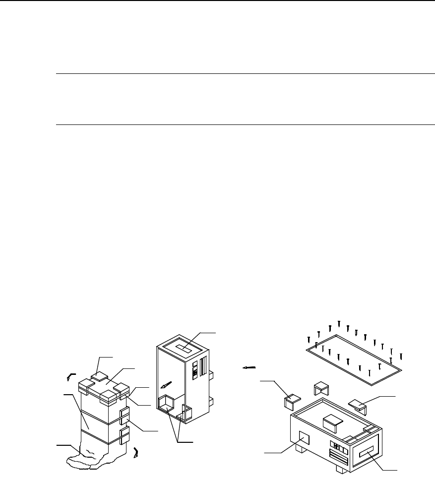
1.6.2 Unpacking Inspection on Wooden Cases
Generally, the wooden case is used to pack heavy items, such as cabinet and feeder
clips, etc.
The packing materials for the cabinet include the wooden case, foamed wrap angles
and a plastic bag, as shown in Figure 1-1. Better not unpack the package until moving it
to or near the equipment room (if enough space is available) so as to avoid damages to
the unpacked cabinet.
(8)
(1)
(2)
(3)
(4)
(5)
(6)
(7)
(3)
(4)
(3)
(7)
(4)
(1) Moisture-proof bag (2) Wooden case back (3) Foamed wrap angle
(4) Wooden case top (5) Wooden case front (6) Pressure-sensitive tap
(7) Foamed L-square (8) Packing label
Figure 1-1 Wooden case
Unpack the package as follows:
1) Pry the outer iron sheet and unpack the cover plate using the nail hammer, the
pliers, the straight screwdriver and the crowbar.
2) Insert a straight screwdriver in the skin plate seam and loosen the plate. Then
insert the crowbar to pry it off the package.
3) Erect the wooden case and take out the equipment. Do not remove the plastic bag
before the equipment is taken out.
Installation Manual
iSiteC BTS3601C CDMA Base Station
Hardware Installation
1 Installation Preparations
1-9
4) Remove the plastic bag.
Inspect the cabinet for the following problems:
l Whether there is any defect on the cabinet appearance;
l Whether the whole cabinet is deformed;
l Whether the environment inside the cabinet is clean;
l Whether other goods such as the storage battery and feeder clip are all there and
intact.
Caution:
1) If the inner packing is damaged, it should be recorded in the report in detail.
2) After unpacking, if there is no internal damage, personnel from Huawei should play the major role in
inspection of the equipment especially the parts whose electrical performance is easily affected. If there is
any damage, Huawei should be responsible for handling or compensation.
3) If any article is found inconsistent with the Packing List, please contact Huawei in time.
4) The checked goods should be organized by type.
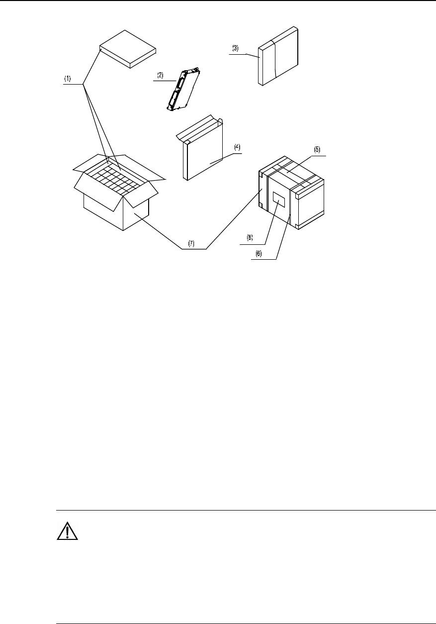
1.6.3 Unpacking Inspection on Cartons
Generally, the carton is used to pack various modules and terminal equipments, etc.
The module is placed in an antistatic bag for transportation. Inside the bag, there is a
desiccant to keep it dry. The packing of a module is shown in Figure 1-2. Antistatic
measures should be taken during the unpacking so as to avoid any damage to the
equipment. Meanwhile, ensure a proper ambient temperature and humidity.
Caution:
When moving the equipment from an environment with a relatively low temperature and humidity and to
that with a relatively high temperature and humidity, unpack it until at least 30 minutes later. Otherwise, the
moisture may condense on the equipment surface and thus cause damage.
Installation Manual
iSiteC BTS3601C CDMA Base Station
Hardware Installation
1 Installation Preparations
1-10
(1) Foam plate (2) Module (3) Antistatic bag (4) Board box
(5) Pressure-sensitive adhesive tape (6) Packing tape (7) Carton (8) Carton label
Figure 1-2 Unpacking of the module
Unpack the carton as follows:
1) Check the type and quantity of the modules as per the carton label;
2) Snip the packing tape using a pair of diagonal pliers;
3) Rip the adhesive tape along the joint seams using a paper knife. Be careful not to
insert the knife too deep, avoiding damage to the modules;
4) Unpack the carton and take out the foam plate;
5) Check whether the quantity marked on the label of the module box is in
compliance with that on the carton label. If yes, take out the module box;
6) Open the module box and take out the module from the antistatic bag.
Caution:
1) Anti-static measures should be taken when holding the modules;
2) When the module box is open, the module shall be seen wrapped in a packing bag and an antistatic bag.
Do not tear or discard these two bags, as they can be used to store the spare modules or to wrap the
failure modules for repair.
Installation Manual
iSiteC BTS3601C CDMA Base Station
Hardware Installation
1 Installation Preparations
1-11
Check the goods after unpacking. The next unpacking cannot be done unless the
present unpacking check has been finished. Make sure that no more modules in the
cartons before opening the next. Avoid discarding the cartons before all modules have
been taken away from it. The check covers:
l Whether the internal packing has been damaged;
l Whether the number and type of the modules are in line with the Packing List;
l Whether there is any broken printed circuit modules or any components detached
from the module.
Caution:
1) For inner packing, any breakage of the inner packaging should be recorded in detail;
2) Check all the boards as per the delivery list. If any nonconformity, contact the vendor immediately.
3) The check goods should be organized by type.
1.6.4 Acceptance and Handover
After the acceptance, both parties must sign on the Packing List to confirm that there is
no problem with the articles. After that, the articles are handed over to the user.
During the inspection, if "outstanding articles" is stated in the Packing List, it is
necessary to feed it back to the order management engineer at the local office. The
order management engineer will urge the relevant department of Huawei to deliver the
outstanding articles as soon as possible and meanwhile sign on the Packing List. In the
case of shortage of articles, wrong articles, extra articles delivered or damage of
articles, both parties should sign the Unpacking Inspection Memo and Packing List.
Meanwhile, the project supervisor should fill in the Article Problem Feedback Form and
feed it back to the order management engineer at the local office within 3 days. The
project supervisor should also be responsible for well keeping the original condition of
articles with problems as well as the inner and outer packing, for future investigation
and verification.
The person assigned by the user will take charge of the articles after the acceptance
and the handover. The articles should be stored in a special room where should have
appropriate temperature and humidity, little shock, little dust, satisfactory antistatic
measures and be rodent-proof and free from any intense electromagnetic interference.
The user should bear the consequences of any damage or loss to the equipment due to
improper storage thereof.
During the implementation, if there are any damaged parts or any other parts need to
be replaced or re-issued, the project personnel should carefully fill in the Article

Installation Manual
iSiteC BTS3601C CDMA Base Station
Hardware Installation
1 Installation Preparations
1-12
Problem Feedback Form and feed it back in time to the article manager at the local
office to put it on records.

Installation Manual
iSiteC BTS3601C CDMA Base Station Table of Contents
i
Table of Contents
2 Installing Cabinet Hardware...............................................................................................2-1
2.1 Hardware Components ..............................................................................................2-1
2.1.1 Component Structure .......................................................................................2-1
2.1.2 Introduction of Hardware Major Equipment ........................................................2-2
2.1.3 Introduction of Hardware Auxiliary Equipment....................................................2-2
2.1.4 Installation Mode..............................................................................................2-3
2.1.5 Installation Flow...............................................................................................2-3
2.2 Installation Planning...................................................................................................2-5
2.2.1 Example of Indoor Wall Installation....................................................................2-5
2.2.2 Example of Indoor Plinth Installation..................................................................2-6
2.2.3 Example of Concrete Pole Installation ...............................................................2-6
2.2.4 Example of Metal Mast Installation on Building-top .............................................2-9
2.2.5 Example of Tower Installation .........................................................................2-11
2.3 Installing Major Equipment .......................................................................................2-13
2.3.1 Installation Flow.............................................................................................2-13
2.3.2 Installing BTS3601C on the Wall .....................................................................2-14
2.3.3 Installing BTS3601C on Plinth.........................................................................2-18
2.3.4 Installing BTS3601C on Metal Mast and Concrete Pole ....................................2-20
2.3.5 Installing Modules ..........................................................................................2-22
2.3.6 Installing Cables ............................................................................................2-24
2.3.7 Installing Shell ...............................................................................................2-30
2.3.8 Installing Sun-shading Cover ..........................................................................2-31
2.4 Installing Auxiliary Equipment ...................................................................................2-31
2.4.1 Installing IAFB ...............................................................................................2-32
2.4.2 Installing AC Lightning Protection Box.............................................................2-33
2.4.3 Installing UPS ................................................................................................2-39
2.4.4 Installing IABB ...............................................................................................2-39
2.5 Installing Cables ......................................................................................................2-47
2.5.1 Cable Connection Requirements.....................................................................2-48
2.5.2 Networking of AC Lightning Protection Box......................................................2-52
2.5.3 Networking of IAFB ........................................................................................2-55
2.5.4 Networking of Inverter ....................................................................................2-65
Installation Manual
iSiteC BTS3601C CDMA Base Station Hardware Installation
2 Installing Cabinet Hardware
2-1
2 Installing Cabinet Hardware
2.1 Hardware Components
Major equipment of Base Transceiver Station (BTS) hardware to be installed include
rack, Micro-bts AC-DC Power Supply Module (MAPM), Micro-bts Base-band
Processing Module (MBPM), Micro-bts Transceiver Module (MTRM), Micro-bts Radio
Frequency Front End Module (MFEM), Micro-bts Power Amplifier Module (MPAM) and
plastic shell. In addition, a sun-shading cover should be installed to ensure the
reliability of BTS that is installed outdoors.
Besides the above major equipment, BTS also comprises auxiliary equipment in actual
installation environment, such as iSite Auxiliary Facility Box (IAFB), AC lightning
protection box, Uninterrupted Power Supply (UPS) and iSite Auxiliary Battery Box
(IABB).
2.1.1 Component Structure
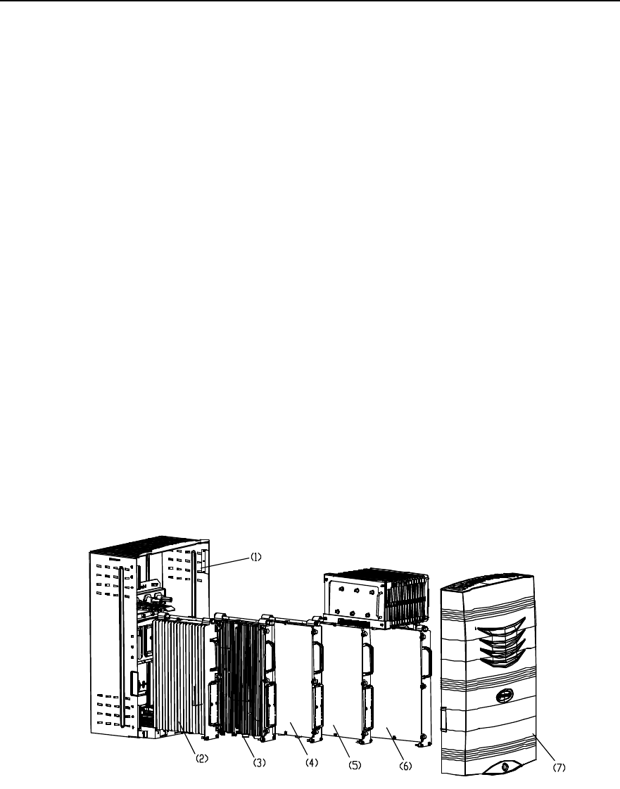
Figure 2-1 shows the major components of the BTS.
1) Rack 2) MAPM 3) MBPM 4) MTRM
5) MFEM 6) MPAM 7) Plastic shell
Figure 2-1 BTS structure

Installation Manual
iSiteC BTS3601C CDMA Base Station Hardware Installation
2 Installing Cabinet Hardware
2-2
2.1.2 Introduction of Hardware Major Equipment
I. Rack
Rack is composed of backplane box, module guide rail, and back shell to bear various
modules.
Backplane box has been fixed on the back shell before delivery. Modules are
connected to the backplane box via connectors, on which waterproof measures have
been taken.
Module guide rail is also fixed on the back shell, along which modules like MAPM,
MBPM, MTRM, MFEM, and MPAM are installed from left to right in their corresponding
slots.
Back shell can be installed via installation accessories on walls, standing supports,
concrete poles, metal masts, towers, etc. That is, there are multiple choices when
determining the BTS site.
II. Modules
Modules are the core of BTS, including MAPM, MBPM, MTRM, MFEM and MPAM.
Each module is sealed for waterproof, and bottom leading-out mode is adopted for their
corresponding cables.
MPAM has been installed with heat-pipe radiator before delivery, so be carefule not to
damage the heat pipe during installation.
III. Plastic shell
Plastic shell is buckled on the rack and then fixed and locked after the cable distribution.
So the installation of major equipment of BTS is completed.
2.1.3 Introduction of Hardware Auxiliary Equipment
Auxiliary equipment of BTS includes IAFB, AC lightning protection box, UPS, and IABB.
All auxiliary equipment can work outdoors and is optional according to actual
installation environment and project requirements.
I. IAFB
IAFB can provide certain assistance for BTS, i.e. it can hold the major auxiliary
equipment of BTS so as to realize the integrated outdoor installation of auxiliary
equipment of the BTS.

Installation Manual
iSiteC BTS3601C CDMA Base Station Hardware Installation
2 Installing Cabinet Hardware
2-3
II. AC lightning protection box
The box helps to realize the ligtning protection for the AC input power of BTS. In terms
of varied discharging currents of the box, it can be classfied into three types 20kA, 40kA
and 100kA. In this manual, all AC lightning protection boxes are of 20kA type.
III. UPS
It is recommended to adopt no-wind UPS with the battery voltage 72V. The packing of
UPS is sunshine-proof, waterproof and moistureproof, so the UPS can operate in
outdoor environment.
IV. IABB
The backup power battery groups of BTS can be placed in the IABB safely satisfying
the backup power supply requirement of the BTS. The box structure is similar to that of
IAFB.
2.1.4 Installation Mode
In terms of environment, the BTS can be installed in the following modes:
l Indoor installation
l Outdoor installation
In terms of conditions, the BTS can be installed in the following modes:
l Wall installation (Installing BTS on wall)
l Plinth installation (Installing BTS on plinth)
l Pole installation (Installing BTS on pole)
l Metal mast installation (Installing BTS on metal mast)
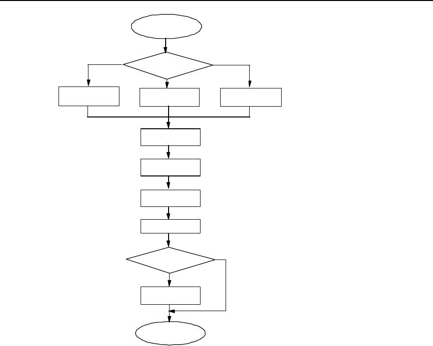
2.1.5 Installation Flow
Installation flow is almost the same no matter which mode is adopted.
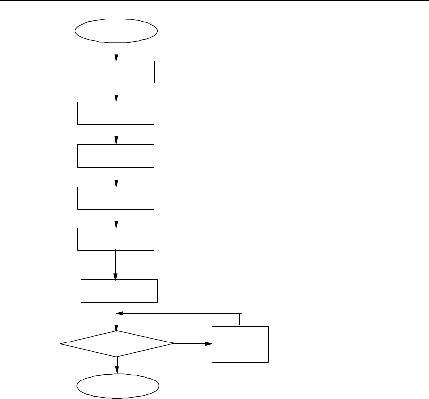
Figure 2-2 shows the installation flow of BTS hardware system.
Installation Manual
iSiteC BTS3601C CDMA Base Station Hardware Installation
2 Installing Cabinet Hardware
2-4
Start
Install major
equipment
Plan
Install auxiliary
equipment
Hardware installation check OK?
End
Reinstall the
relevant part
N
Y
Install antenna and feeder
system
Install cables
Install GPS antenna and
feeder system
Figure 2-2 Hardware installation flow
I. Description
1) Planning
You can start to install the BTS only after plans have been made for the installation
positions and cable distribution of all equipment, and relevant support equipment like
supports and masts have been prepared.
2) Installing major equipment
BTS major equipment refers to the hardware equipment that accomplishes the major
functions of the BTS.
3) Installing auxiliary equipment
BTS auxiliary equipment refers to the equipment that provides power and functions like
lightning protection and transmission for the major equipment of the BTS.
Installation Manual
iSiteC BTS3601C CDMA Base Station Hardware Installation
2 Installing Cabinet Hardware
2-5
4) Installing cables
Connect cables among all above equipment after their installation. Cables include
transmission cables, power cables and grounding cables.
5) Installing antenna and feeder system
Installing antenna and feeder system is to install antennae, prepare connectors, etc.
6) Installing GPS antenna and feeder system
Installing GPS antenna and feeder system is to install GPS receive antenna and
lightning arrester, prepare connectors, etc.
7) Checking hardware installation
Check the installation quality and accept the installation of BTS hardware upon
completion.
2.2 Installation Planning
Following are several typical installation layout examples for reference.
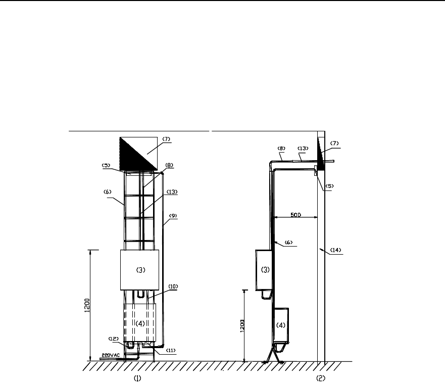
2.2.1 Example of Indoor Wall Installation
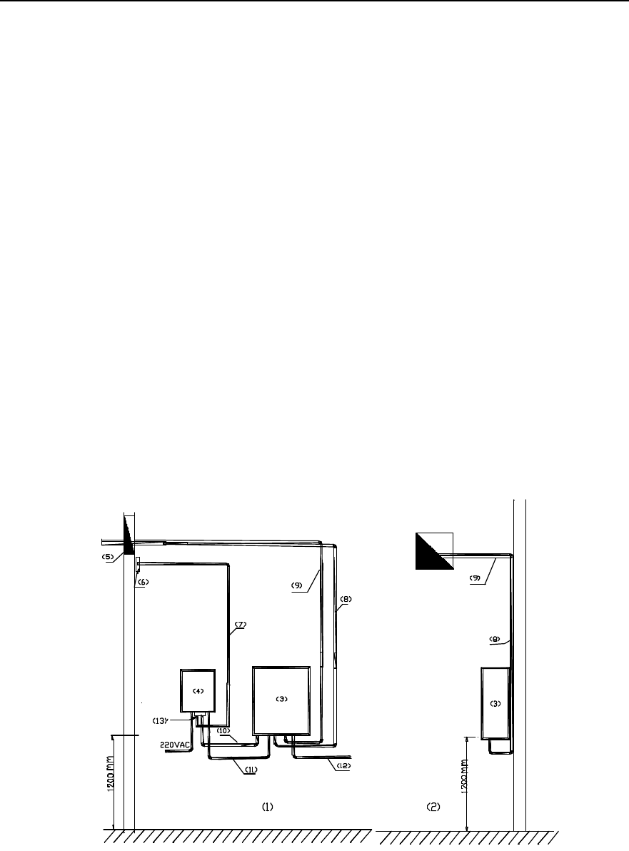
Figure 2-3 shows the indoor wall installation of BTS with IAFB.
1) Front view 2) Side view 3) BTS3601C
4) IAFB 5) Feeder window 6) Indoor grounding bar
7) Protection Ground (PGND) bus 8) Global Positioning System (GPS) feeder 9) Jumper
10) BTS PGND cable 11) Power cable 12) Fiber
13) IAFB grounding bar
Figure 2-3 Installing BTS on the wall
Installation Manual
iSiteC BTS3601C CDMA Base Station Hardware Installation
2 Installing Cabinet Hardware
2-6
2.2.2 Example of Indoor Plinth Installation
Inside the equipment room, if BTS cannot be installed on the wall (e.g. structure pole,
hollow wall body, clapboard wall in the simplified equipment room), it can be installed
on the plinth. The position of the plinth should be as close to the wall as possible.
Figure 2-4 shows the indoor plinth installation of BTS with IAFB.
1) Front view 2) Side view 3) BTS3601C
4) IAFB 5) Indoor grounding bar 6) Support
7) Feeder window 8) Jumper 9) Protection grounding
10) BTS3601C PGND cable 11) IAFB grounding bar 12) Power cable
13) GPS feeder 14) Wall
Figure 2-4 Installing BTS3601C on the plinth
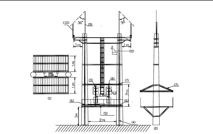
2.2.3 Example of Concrete Pole Installation
This installation mode applies to such environment as fields, villages, towns, road sides,
etc. to cover the locations like villages and towns. In this case, two poles must be used
in the installation no matter that the BTS to be installed is an omni BTS or a directional
one.
I. Facility requirements
l The standard spacing between two poles should be 5m (not less than 3.5m at
least), and horizontal diversity distance between two antennae should be 6m (not
less than 5m at least). For an omni BTS, a metal mast should be used to meet the

Installation Manual
iSiteC BTS3601C CDMA Base Station Hardware Installation
2 Installing Cabinet Hardware
2-7
requirements for horizontal diversity between two antennae. For a directional BTS,
only a dual polarization antenna is required and the spacing between two poles
should be determined for the convenience of platform establishment.
l If the platform is established 3m above the ground, for an O(1) BTS, the platform
should be strong enough to bear the load over 500kg; for an S(1/1/1) BTS, the
platform is required to bear the load over 1500kg.
l Between two poles, two or more metal fixing beams should be installed. And at the
joints between beams and poles, the beams should be welded reliably with the
down leads of pole lightning arresters. Dot welding is not allowed. It is
recommended to install a metal fixing beam respectively on the platform and at the
place 2m above the platform. And install two (according to the type of BTS) 2m
metal holding supports between two beams by soldering so as to bear the
BTS3601C and other equipment. The diameter of each holding support is
60mm~114mm, and the spacing between them is 80cm.
l Install a vertical cabling ladder (300mm wide) via the metal fixing beam between
two poles. The lower end of the ladder should be 1.2m away from the platform.
Connect the fixing beams, on which the cabling ladder is fixed, to the flat steel (for
lightning protection and grounding) by soldering. Dot welding is not allowed.
l The antenna support is made of steel pipe with the diameter 60mm~114mm. The
omni antenna should be 1m away from the antenna support horizontally. In the
case of a directional antenna, its holding support may remain unextended.
II. Layout
Figure 2-5 shows the installation of BTS3601C by two concrete poles.
Installation Manual
iSiteC BTS3601C CDMA Base Station Hardware Installation
2 Installing Cabinet Hardware
2-8
1) Top view 2) Side view 3) BTS3601C
4) Lightning protection grounding flat steel 5) Grounding bar 6) Soldering point
7) Sun-shading cover 8) Holding support 9) Lightning arrester
10) Omni antenna 11) GPS antenna
Figure 2-5 Installing BTS3601C on two poles
III. Note
l To facilitate the introduction of power cables and trunk cables, first determine the
metal holding support on which the BTS3601C is to be installed. IAFB or AC
lightning protection box can be installed below the BTS3601C. The IABB can be
fixed on the platform directly. If more than 2 battery boxes are needed, a platform
should be established below the platform.
l Equipment like the BTS3601C, IAFB, UPS, etc. should be installed between two
poles via metal parts. It is not allowed to directly install them on poles.
l When feeders are used, the antenna jumpers should be bound on the crosspieces
of poles via cable ties. For the convenience of feeder connector preparation and
maintenance, it is prohibited to lay feeders transversely. The feeders should be
routed along the sides of the cabling rack.
l If the poles are not long enough, it is recommended to connect the antenna and
the BTS3601C via jumper. And the jumper should be bound at the sides of the
cabling rack and on the crosspieces of poles via cable ties. Both ends of the
jumper should be grounded.
l Lightning arresters should be respectively installed on two poles, and the antenna
of the BTS3601C should be in the protection range of the two arresters (pitch

Installation Manual
iSiteC BTS3601C CDMA Base Station Hardware Installation
2 Installing Cabinet Hardware
2-9
angle 30°C between them), as shown in Figure 2-5. The 40mm%4mm
hot-gavanlizing flat steel should be used as the downleads of arresters.
l The external shielding layer of the BTS3601C antenna and feeder should be
grounded at the bottom of the antenna and at the front end beofore they are
connected to the BTS3601C. The grounding cable should be connected to the
cabling ladder or other metal grounding parts. The grounding cable should be
made of yellow-green (or black) plastic insulation copper wire with the core
diameter not less than 6mm2.
l Grounding bar can be installed on the metal holding support, or fixing beam, or
platform directly and reliable electric connection should be achieved among the
grounding bar and the metal parts aforementioned. A dedicated grounding
downlead should be installed on the grounding bar and be connected to the
counterpoise.
l Power cables and trunk cables should not be winded or bound on the arresters or
their downleads, instead, these cables should be kept as far as possible from the
downleads of arresters. Power cables and signal cables should be distributed
horizontally and the spacing between any two cables should be at least 5cm. And
they should not be routed vertically and crossly.
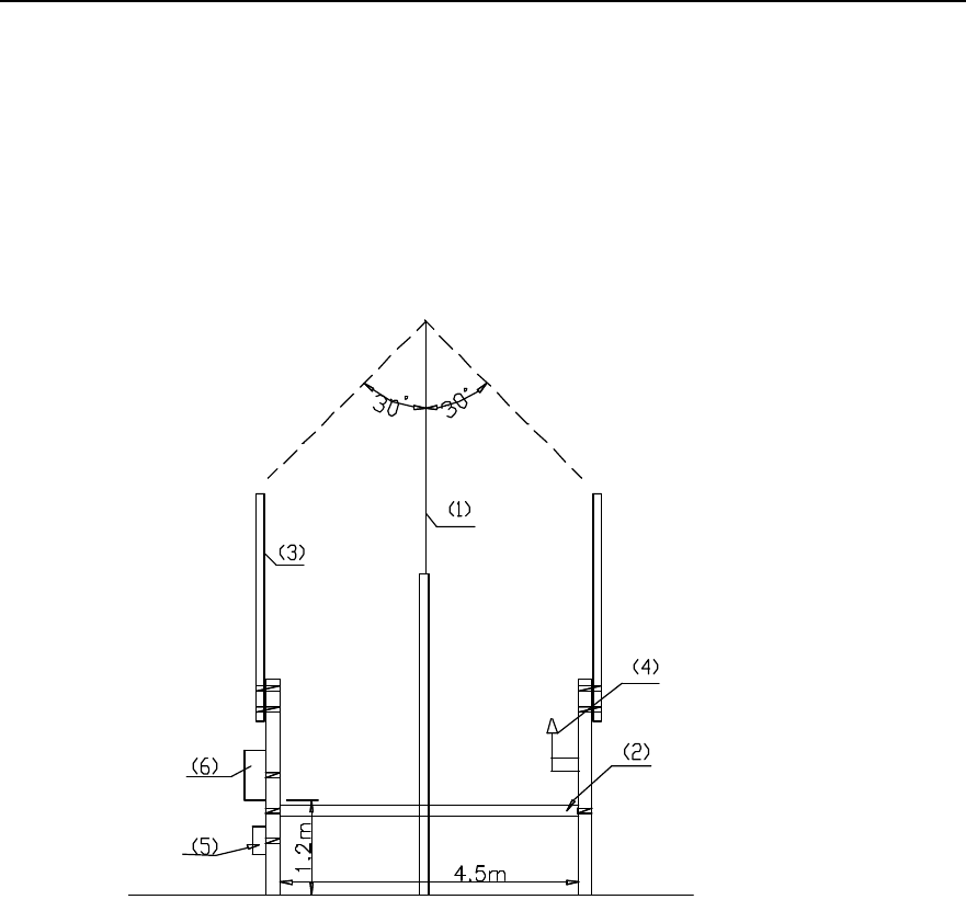
2.2.4 Example of Metal Mast Installation on Building-top
Such installation of BTS3601C is applied for the coverage of villages and towns.
I. Facility requirements
l For an omni BTS, 3 masts should be used (one is used to install the lightning
arrester and the other two to install two monopole omni antennae. The spacing
between the latter two masts should be over 4.5m. Two masts are generally used
for a directional BTS, as dual polarization antenna is adopted for the BTS.
l The length of the mast should be determined by the height of the BTS3601C
antenna. However, based on the conditions on building-top, the mast length
should not be more than 8m.
l The mast should be made of steel pipe with sufficient intensity and the dialmeter
from 60mm to 114mm. Each mast must be secured by three steep ropes at least.
l A cabling rack should be installed between the masts on which the antenna is
fixed. Its height should be lower than 1.2m.
l The PGND bar should be fixed to the AC lightning protection box or at the bottom
of the IAFB mast and close to the building wall. Following are three methods to
connect the PGND cables:
a) If the equipment room is located in the building, lead the grounding cable from
the building-top to the grounding bar in the equipment room;
b) Connect the grounding cable to the counterpoise at the building bottom;
Installation Manual
iSiteC BTS3601C CDMA Base Station Hardware Installation
2 Installing Cabinet Hardware
2-10
c) Connect the grounding cable to the lightning protection zone on the
building-top.
II. Installation layout of an omni BTS3601C
As shown in Figure 2-6, the mast in middle is used to install the lightning arrester; while
in the rest two masts, the one being installed with BTS3601C is called master mast,
and the other is called slave mast.
1) Lightning arrester 2) Cabling Rack 3) Antenna
4) GPS antenna 5) IAFB 6) BTS3601C
Figure 2-6 Omni BTS3601C installation on metal masts
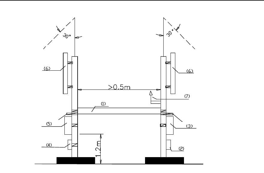
III. Installation layout of a directional BTS3601C
Figure 2-7 shows the installation of a directional BTS3601C cascaded with an
ODU3601C. The mast, on which the BTS3601C is installed, is called master mast, and
the one where the ODU3601C is instaled is called slave mast.
Installation Manual
iSiteC BTS3601C CDMA Base Station Hardware Installation
2 Installing Cabinet Hardware
2-11
1) Cabling rack for feeder 2) IAFB 3) BTS3601C 4) AC lightning protection box
5) ODU3601C 6) Directional antenna 7) GPS antenna
Figure 2-7 Directional BTS3601C installation on metal masts
IV. Note
l First determine the mast on which the BTS3601C is to be installed during the
planning.
l For antenna jumper and feeder routed vertically, bind them on the metal masts
with the spacing of 30cm via black cable ties; for antenna feeder routed along the
cabling rack, fix them with the spacing of 1m or 2m via feeder clips.
l Power cables from BTS3601C to ODU3601C should be protected by metal tubes,
and fibers for cascading by currgated tube. Power cables and fibers routed
vertically should be bound on the metal masts via black cable ties, and those
routed horizontally should be bound to the cabling rack.
l Power cables should be distributed along the outer side of the cabling rack, and far
away from the fibers and feeders.
2.2.5 Example of Tower Installation
This mode is applied to such locations as fields, villages, towns, and roadsides to cover
villages, roads, etc. In this mode, the hoisting of BTS3601C is involved.
Installation Manual
iSiteC BTS3601C CDMA Base Station Hardware Installation
2 Installing Cabinet Hardware
2-12
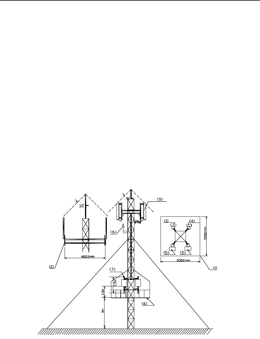
I. Facility requirements
l The support on which the directional antenna is installed should be extended out
of the platform for at least 0.5m. Proper support length of the omni antenna should
be determined to meet the requirements for the horizontal diversity distance (over
4.5m) between two antennae.
l The diameter of the holding support on which the antenna is installed should be
60mm~114mm. The length (generally, omni antenna: 1m; directional antenna: 3m)
of it should be determined according to the antenna type and sizes.
l A square platform(3m % 3m) should be established 3m above the ground with the
bearer capability more than 500kg. And a sun-shading shed should be established
3m above the platform.
l A 2m holding support should be fixed to the tower body vertically above the
platform so as to install BTS3601C, IAFB, etc. The number of supports is
determined by the number of BTS3601Cs, and the diameter of each support
should be 60mm~114mm.
II. Installation layout
Figure 2-8 shows the layout of BTS3601C installation on tower.
1) Top view 2) Side view 3) Lightning arrester
4) IAFB 5) BTS3601C 6) GPS antenna
7) Holding support 8) Platform 9) Directional antenna
Figure 2-8 Installing BTS3601C on tower

Installation Manual
iSiteC BTS3601C CDMA Base Station Hardware Installation
2 Installing Cabinet Hardware
2-13
III. Note
l When hoisting the BTS3601C, try to avoid any collision between BTS3601C and
the tower.
l Distribute feeders along one side of the tower evenly and tidily. And all feeders
should be fixed via feeder dual-clips.
l Install AC lightning protection box and grounding busbar on one support, and the
BTS3601C on the other. If the BTS3601C is cascaded with other BTS3601Cs,
install them on other supports.
l Install PGND bar on the tower directly. And its location should be close (the PGND
cable length should not be more than 1m) to AC lightning protection box. It should
have its dedicated grounding downlead (made of 40mm % 4mm hot-gavanlizing
flat steel). PGND bar and its downlead should be connected via 35mm2
yellow-green plastic insulation copper wire or welded directly. Neither the bar nor
the downlead should be insulated from the tower body.
l The external shielding layer of BTS3601C coaxial feeder should be grounded on
tower top and grounded before the feeder is connected to the BTS3601C. The
grounding cable should be connected to the tower body. The grounding cable
should be made of yellow-green (or black) plastic insulation copper wire with the
core diameter not less than 6mm2.
l Power cables and signal cables of BTS3601C should not be winded or bound on
the tower. They should be cabled as horizontally as possible.
2.3 Installing Major Equipment
2.3.1 Installation Flow
Figure 2-9 shows the flow to install BTS3601C major equipment:
Installation Manual
iSiteC BTS3601C CDMA Base Station Hardware Installation
2 Installing Cabinet Hardware
2-14
Start
Wall
installation Select installation
mode
Metal mast or pole
installation
Install bracket Install plinth Install fastener
set
Install rack
Install modules
Install shell
End
Outdoor installation?
Install sun-shading
cover
Y
N
Install cables
Plinth installation
Figure 2-9 BTS3601C major equipment installation flow
In terms of different installation modes of racks, the BTS3601C installation comprises
wall installation, plinth installation, and metal mast and concrete pole instllation.
Following is to introduce the specific process of the above three modes.
2.3.2 Installing BTS3601C on the Wall
I. Installing bracket
During the installation, a bracket should be installed to secure the BTS3601C onto the
wall. Figure 2-10 shows the installation flow:
Installation Manual
iSiteC BTS3601C CDMA Base Station Hardware Installation
2 Installing Cabinet Hardware
2-15
Mark
Drill holes
Install expansion bolts
Fix bracket
Figure 2-10 Installing the bracket
1) Position and mark the places on the wall to install expansion bolts. Figure 2-11
shows the appearance of an expansion bolt.
1) M12 expansion bolt
Figure 2-11 Positioning holes
2) Drill holes on the marked places via a percussion drill with the drill bit of v16, the
holes should be 52mm~60mm deep and should have the same depth. After the
drilling, remove the dust inside and outside the holes with a vacuum cleaner, and
then check the distance among holes. Whenever big errors occur, the relevant
hole must be positioned and drilled again.
Installation Manual
iSiteC BTS3601C CDMA Base Station Hardware Installation
2 Installing Cabinet Hardware
2-16
Caution:
1) Hold the drilling bit vertical to the wall during drilling. Hold tight the drillstock with two hands to keep it in
the right direction, as vibrations may lead to damaged wall and the hole not straight.
2) The holes should be 52mm~60mm deep and should have the same depth. Otherwise, the expansion
bolts can not be secured.
3) If the wall is too hard and smooth to settle the drill bit, punch a pit with a chisel to help positioning the
hole.
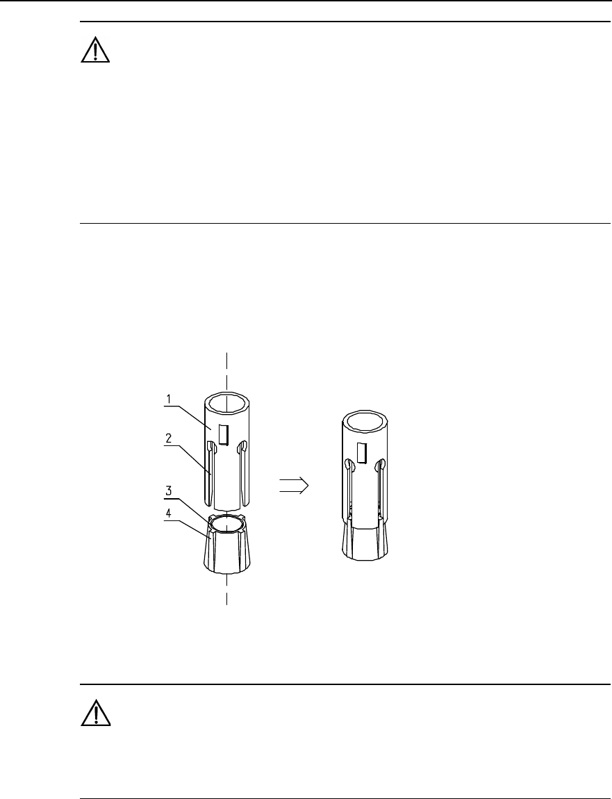
3) Remove the bolt sleeve and nut and put the sleeve and nut vertically into the hole
(before this, the guiding fins should be installed on the slots of the sleeve).
Hammer the bolt sleeve until it completely goes into the ground. Figure 2-12
shows the installation of the bolt sleeve and nut.
1) Bolt sleeve 2) Guiding slot 3) Nut 4) Guiding fin
Figure 2-12 Installation of the bolt sleeve and nut
Caution:
The guiding fins should be installed on the bolt sleeve first. Otherwise, the expansion bolt can not be
properly installed and secured.
4) Put the bracket onto the bolt, and make it droop down naturally. Then mark the
places where the rest three bolts are to be inserted.
5) Drill the holes and install the expansion bolts as mentioned above.
6) Align the bracket with four expansion bolts and put the bracket onto the wall. Then
in turn put insulation coverings, big plain washers, spring washers v12 and M12
Installation Manual
iSiteC BTS3601C CDMA Base Station Hardware Installation
2 Installing Cabinet Hardware
2-17
nuts on the four bolts, and tighten all four nuts to a torque of 45 N$m so as to make
the expansion bolts expanded and fix the bracket on the wall.
Caution:
Before securing the nuts, put the washers first onto them. The exposed part of the bolt should be about
20mm long.
II. Installing rack
1) Hang the rack onto the bracket, and make the four white washers at the rear of the
rack alligned with four installation holes on the bracket, as shwon in Figure 2-13.
1) Hanger (at the rear of the rack) 2) White washer
Figure 2-13 Installing rack onto bracket
2) Starting from the inside of the rack, secure the two screws at the upper part of the
rack, then the two at the lower part, as shown in Figure 2-14.
Installation Manual
iSiteC BTS3601C CDMA Base Station Hardware Installation
2 Installing Cabinet Hardware
2-18
1) Rack 2) M10%45 screw 3) Bracket
Figure 2-14 Installing rack onto wall
Caution:
Check the levelness of the rack after the installation and confirm the result not over 1° so as to ensure the
cooling of the MPAM. Otherwise, adjust it till it is OK.
2.3.3 Installing BTS3601C on Plinth
I. Installing plinth
Generally, this mode is applied to the indoor environment.
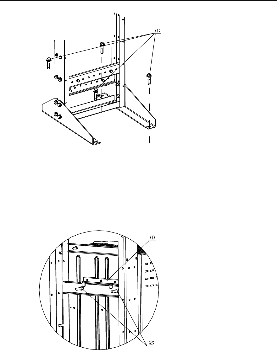
1) Place the plinth on the floor, and mark the positions of all 4 connection holes of the
plinth on the floor.
2) Drill holes using a percussion drill with the drill bit of v16, and begin to install the
expansion bolts. The installation of expansion bolts is available in the section
“2.3.2 Installing BTS3601C on the Wall”.
3) Lift the plinth by two persons, align it with the four expansion bolts and place it
onto the floor. Confirm the levelness of the plinth and then in turn put insulation
coverings, big plain washers, spring washers v12 and M12 nuts onto the four
expansion bolts. Then alternatively fasten the nuts to a torque of 45 N$m so as to
make the bolts expanded and secure the plinth, as shown in Figure 2-15.
Installation Manual
iSiteC BTS3601C CDMA Base Station Hardware Installation
2 Installing Cabinet Hardware
2-19
1) M12%60 expansion bolt
Figure 2-15 Fixing the plinth
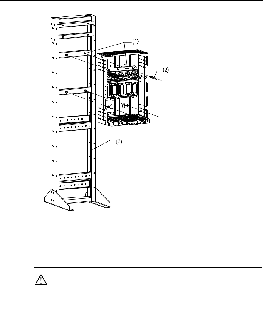
II. Installing rack
1) Align the four white washers at the rear of the rack with the four installation holes
on the plinth, and then place the rack onto the plinth, as shown in Figure 2-16.
1) Hanger (at the rear of the rack) 2) Installation holes on the plinth
Figure 2-16 Placing rack onto plinth
2) Starting from the inside of the rack, fasten the two screws at the upper part of the
rack, then the two at the lower part, as shown in Figure 2-17.
Installation Manual
iSiteC BTS3601C CDMA Base Station Hardware Installation
2 Installing Cabinet Hardware
2-20
1) Installation hole 2) M10%50 bolt 3) Plinth
Figure 2-17 Securing rack onto plinth
Caution:
Check the levelness of the rack after the installation and confirm the result not over 1° so as to ensure the
cooling of the MPAM. Otherwise, adjust it till it is OK.
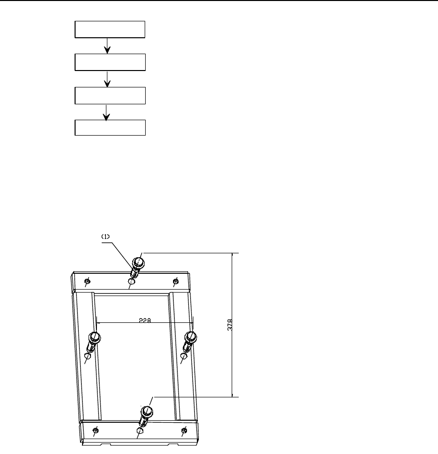
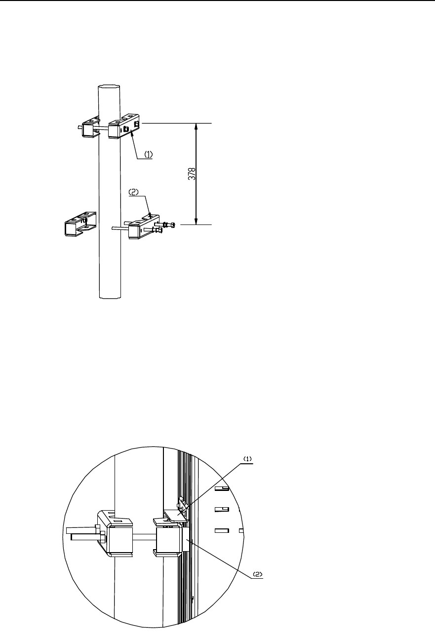
2.3.4 Installing BTS3601C on Metal Mast and Concrete Pole
I. Installing fastener sets
This installation mode comprises BTS3601C installation on metal masts and poles. To
fix the rack onto them, fastener sets should be installed first.
Installation Manual
iSiteC BTS3601C CDMA Base Station Hardware Installation
2 Installing Cabinet Hardware
2-21
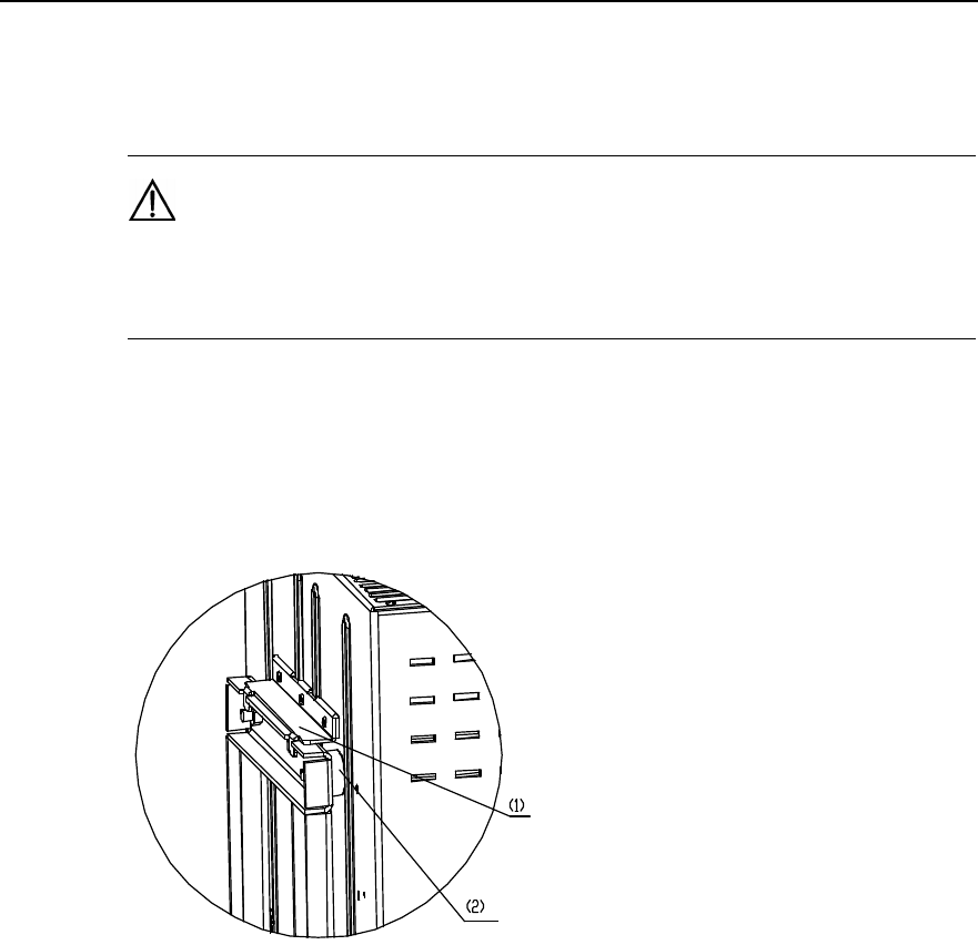
1) Fix the fastener set 1 with M10 bolt onto the upper part of the holding support, then
the fastener set 2 onto the lower part of the mast or pole.
2) Adjust the spacing between the center points of two fastener sets to 378mm, as
shown in Figure 2-18.
1) Fastener set 1 2) Fastener set 2
Figure 2-18 Installing fastener sets
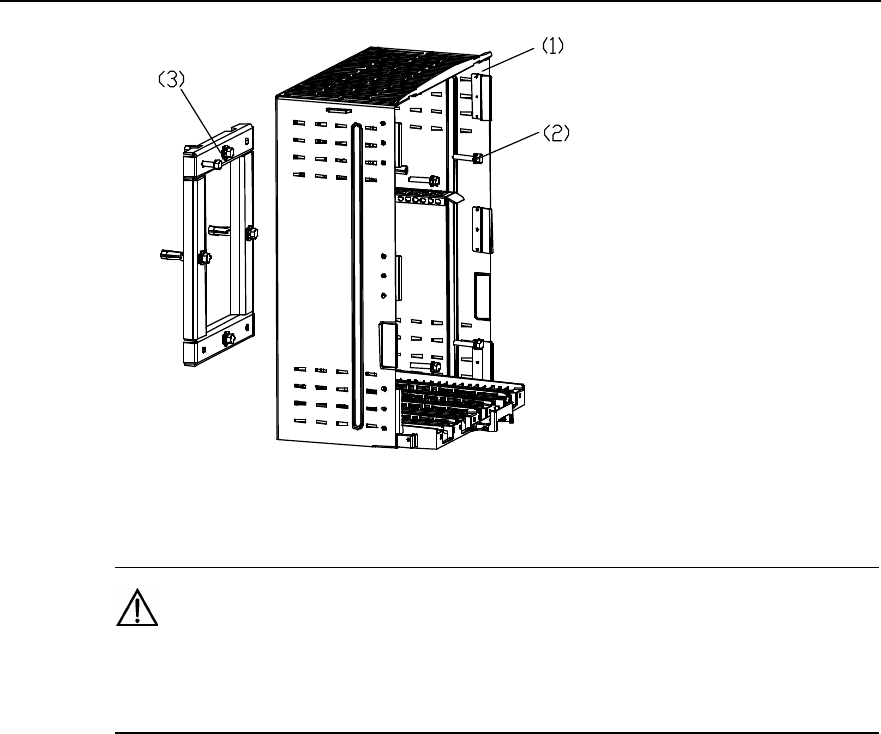
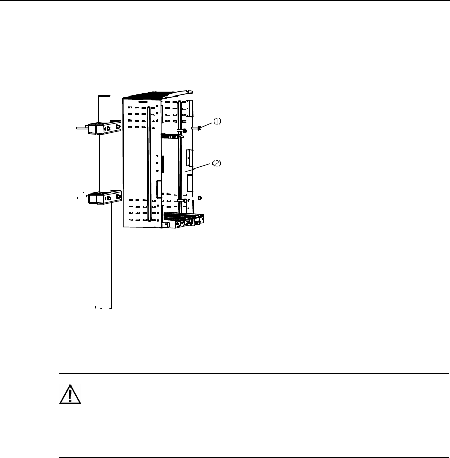
II. Installing rack
1) Align the four white washers at the rear of the rack with the four installation holes
on the fastener sets and then place the rack into the slots of two fastener sets, as
shown in Figure 2-19.
1) Hanger (at the rear of the rack) 2) White washer
Figure 2-19 Fixing rack with fasteners
Installation Manual
iSiteC BTS3601C CDMA Base Station Hardware Installation
2 Installing Cabinet Hardware
2-22
2) Starting from the inside of the rack, install the two M4%45 screws at the upper part
of the rack, then check the correspondence between the two screws (at the lower
part) and the fastener set 2. If OK, tighen the screws; otherwise, adjust the position
of fastener set 2, as shown in Figure 2-20.
1) M4%45 screw 2) Rack
Figure 2-20 Fixing the rack
Caution:
Check the levelness of the rack after the installation and confirm the result not over 1° so as to ensure the
cooling of the MPAM. Otherwise, adjust it till it is OK.
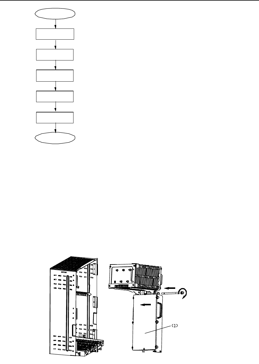
2.3.5 Installing Modules
Modules of BTS3601C are generally installed by the sequence from right to left, i.e.
MPAM-MFEM-MTRM-MBPM-MAPM. During the installation, refer to their names on
the front of the modules and the corresponding names on the backplane, then insert
them into the corresponding slots.
Figure 2-21 shows the installation flow of modules.
Installation Manual
iSiteC BTS3601C CDMA Base Station Hardware Installation
2 Installing Cabinet Hardware
2-23
Start
Install MFEM
Install MTRM
Install MPAM
End
Install MBPM
Install MAPM
Figure 2-21 Module installation flow
All modules are installed as per the same process. Following is to describe the
installation process of the MPAM as an example.
1) Hold the bottom of the MPAM with the left hand, and the handle of the MPAM with
the right hand, then insert it into the position along the guide rail.
2) Tighten the M10 bolts at the upper part of the module and the two M6 fixing bolts at
the lower part alternatively for module fixation and waterproof, as shown in Figure
2-22.
1) MPAM
Figure 2-22 Installing MPAM
Installation Manual
iSiteC BTS3601C CDMA Base Station Hardware Installation
2 Installing Cabinet Hardware
2-24
Caution:
1) Two persons are required during the installation as heat-pipe radiator has been installed onto the
MPAM before delivery and the MPAM is heavy. If the heat-pipe radiator interferes with the support for the
radiator on the rack, remove the support first and then install it back to position after the installation.
2) After the installation of the MTRM, check the position of the TRX_ID Dual In-Line Packet (DIP) switch in
the maintenance window on the module panel. On the switch, "ON" indicates the low bit, and "OFF"
indicates the high bit. To ensure the normal operation of BTS3601C, its three low bits should all be set to
"ON(000)".
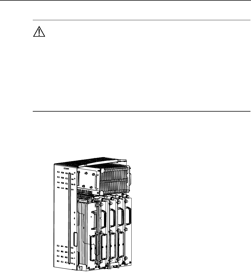
3) In turn, install MFEM, MTRM, MBPM and MAPM. The procedures are the same as
those of MPAM. Figure 2-23 shows the installed modules.
Figure 2-23 Installed modules
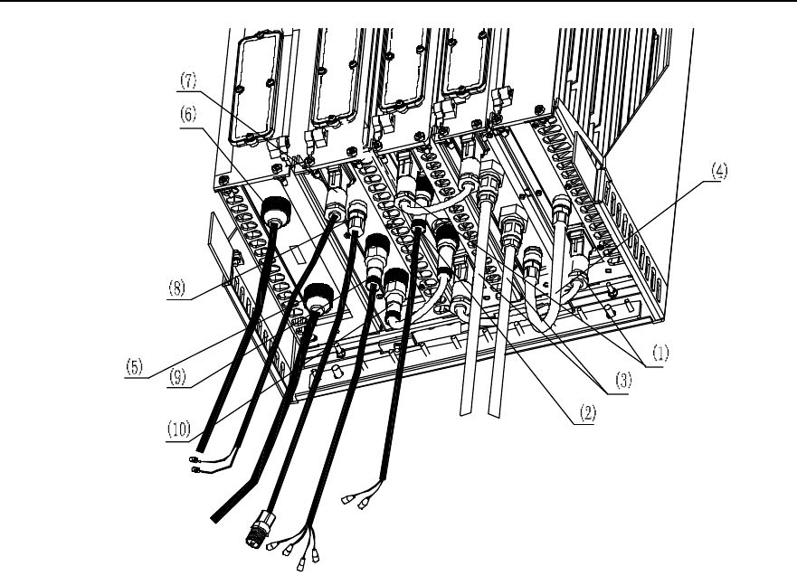
2.3.6 Installing Cables
I. Cable types
At the site, such cables should be connected for the BTS3601C as Radio Frequency
(RF) jumpers, Frequency Hopping (FH) cables, external cables, fibers, etc. Figure 2-24
shows the entire cable distribution of the BTS3601C.
Installation Manual
iSiteC BTS3601C CDMA Base Station Hardware Installation
2 Installing Cabinet Hardware
2-25
1) Cables connecting Type D
connectors between modules 2) MTRM fiber cascading connector 3) Antenna feeder DIN
connector connecting to feeder
4) Inter-module cables between
Type N male connectors 5) DC input power cable of battery 6) AC power input cable
7) MBPM E1 cable 8) GPS cable (Type N connector)
9) Fiber connector for MBPM
optical transmission 10) Fiber connector from MBPM to MTRM
Figure 2-24 BTS3601C cable connection
Following are the details of the cable distribution of modules:
1) Inter-module RF jumpers
l RF jumper (Type D connector) between MTRM and MFEM;
l RF jumper (Type D connector) between MPAM and MTRM;
l RF jumper (Type N connector) between MPAM and MFEM;
l E1 cable (when E1 cable is used for transmission) connecting to MBPM.
2) Fiber
l Fiber cascading connector (waterproof fiber connector) connected with MTRM
fiber interface;
l Fiber connector (waterproof fiber connector) between MBPM and MTRM;
l Fiber connector (when fiber isd used for transmission) connecting to MBPM.
3) External cables
l RF jumpers (DIN connector) connecting to the antenna feeder interface of the
MFEM;
l RF jumper (Type N connector) connecting to the GPS interface of the MBPM;
Installation Manual
iSiteC BTS3601C CDMA Base Station Hardware Installation
2 Installing Cabinet Hardware
2-26
l Power cable connecting to MAPM;
l Grounding cable between cabinet and PGND bar.
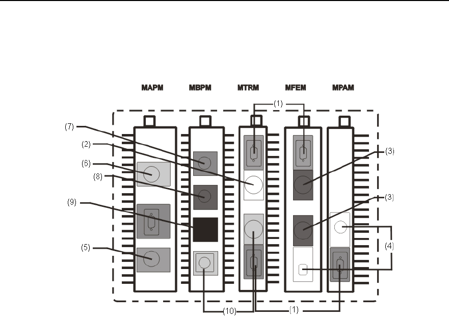
Figure 2-25 shows the cable distribution at the bottoms of BTS3601C modules.
1) Cables connecting Type D
connectors between modules. 2) MTRM fiber cascading
connector 3) Antenna feeder DIN
connector connecting to feeder
4) Inter-module cable between
Type N male connectors 5) DC input power cable of
battery 6) AC power input cable
7) MBPM E1 cable 8) GPS cable (Type N
connector)
9) MBPM optical transmission
fiber connector cable 10) Fiber connector connecting
MBPM to MTRM
Figure 2-25 Cable distribution at the bottom of BTS3601C
II. Cabling sequence
Waterproof measures and bottom lead-out mode is adopted during the cable
distribution of the BTS3601C. And the distribution follows the sequence inside-outside:
1) Connect Type D RF jumper between MPAM and MTRM, and fasten it with straight
screwdriver;
2) Connect Type N RF jumper between MPAM and MFEM and make waterproof
treatment for the connector via three types of tapes;
3) Connect DIN RF jumper from the antenna and feeder interface of MFEM to the
feeder and take waterproof measures for the connector via three types of tapes;
4) Connect Type N RF jumper between MFEM and MPAM and take waterproof
measures for the connector via three types of tapes;
5) Connect Type D RF jumpes respectively from MTRM to MFEM and MPAM, then
fasten them with straight screwdriver;
Installation Manual
iSiteC BTS3601C CDMA Base Station Hardware Installation
2 Installing Cabinet Hardware
2-27
6) Connect the fiber between MTRM and MBPM (The silkscreen "UP_FIBER" is
made on the fiber interface at the bottom of MTRM). If fiber cascading is necessary,
connect the fiber cascading connector to the cascading fiber interface of the
MTRM (The silkscreen "DOWN_FIBER" is made on the bottom of the cascading
fiber interface);
7) When E1 cable is used for transmission, connect the E1 trunk cable to the E1
interface of MBPM; when fiber is usded for transmission, connect the pigtail of the
fiber to the fiber interface of MBPM;
8) Connect GPS cablesd under MBPM and take waterproof measures for the
connector via three types of tapes;
9) Connect power cables to MAPM;
10) Connect grounding cables between the cabinet and the PGND bar.
Caution:
If fibers are used for transmission, the optical transmission fiber connector at the bottom of the MBPM
should be connected. That is, connect one end of the connector to MBPM and extend four pigtails (marked
as WTX, WRX, ETX, and ERX respectively) from the other end. Connect the pigtails "WTX" and "WRX" to
the upper-level BTS or BSC, and pigtails "ETX" and "ERX" to the lower-level BTS. Note the marks on the
fibers and connect them correctly.
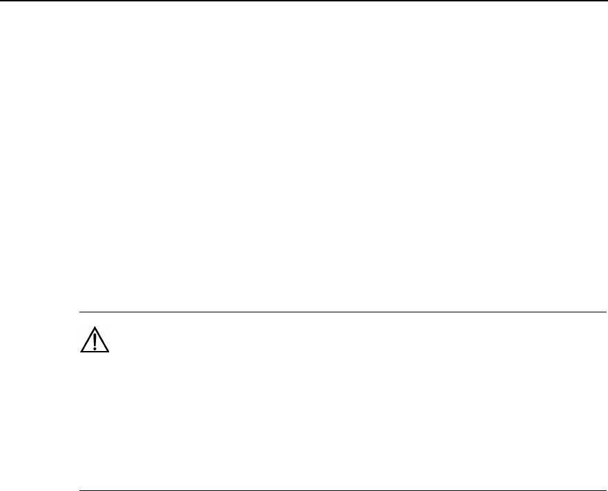
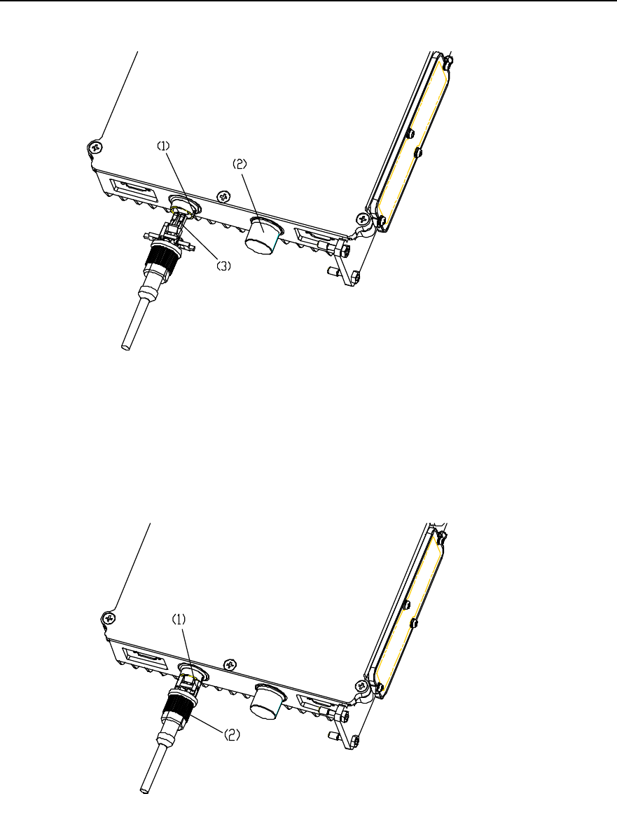
III. Procedures to distribute the waterproof fibers at the bottom of MTRM
During the distribution, be careful not to break the core wire of the fiber connector.
1) Unfix the dustproof cover on the waterproof fiber, and make the dual-LC fiber
connector exposed, as shown in Figure 2-26.
Installation Manual
iSiteC BTS3601C CDMA Base Station Hardware Installation
2 Installing Cabinet Hardware
2-28
1) Dustproof cover 2) Dual-LC fiber connector
Figure 2-26 Appearance of waterproof fiber (figure 1)
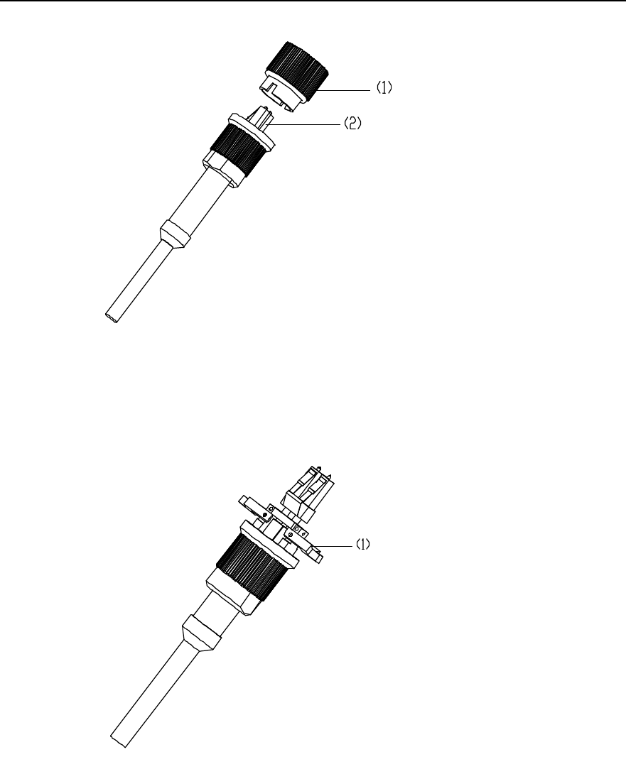
2) Unwrap the limit pivoted arm, as shown in Figure 2-27.
1) Limit pivoted arm
Figure 2-27 Appearance of waterproof fiber (figure 2)
3) Unfix the waterproof cover from the MTRM fiber interface; align the dual-LC fiber
connector with the fiber interface. Make the limit pivoted arm correspond to the
locating slot of the fiber interface. Then insert the connector into the fiber interface
gently until a sound is heard indicating that the connector is in position, as shown
in Figure 2-28.
Installation Manual
iSiteC BTS3601C CDMA Base Station Hardware Installation
2 Installing Cabinet Hardware
2-29
1) Fiber connector locating slot 2) waterproof cover 3) Dual-LC fiber connector
Figure 2-28 Installing waterproof fiber (1)
4) Fix the limit pivoted arm into the corresponding locating slot and tighten the
external nut. The installation is then complete. See Figure 2-29.
1) Fixing the limit pivoted arm into the locating slot 2) External nut
Figure 2-29 Installing waterproof fiber (2)
Installation Manual
iSiteC BTS3601C CDMA Base Station Hardware Installation
2 Installing Cabinet Hardware
2-30
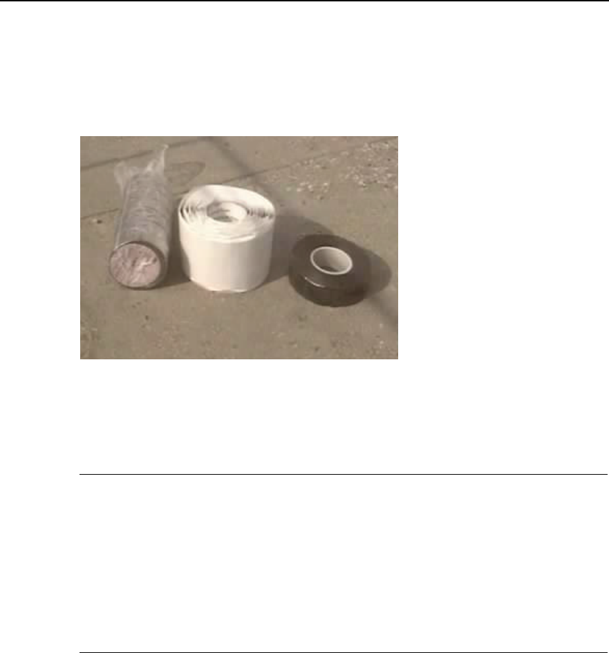
IV. Waterproof measures
Except the power cable connectors, fibers and Type D connectors, waterproof
measures should be taken for Type N/DIN connectors. Figure 2-30 shows the
waterproof sealing tapes.
(1) (2) (3)
1) Electrical insulation tape 2) Semi-conductive single-coated tape 3) Waterproof tape
Figure 2-30 Waterproof sealing tapes
&
Note:
1) Seal the connector as follows: Wrap it up with semi-conductive single-coated tape, and then with
waterproof tape, finally with electrical insulation tape. When wrapping, do it from the bottom up, then from
the top to the bottom and finally from the bottom up again. Each turn should be overlapped by the next turn
for about one-third of the width.
2) For the convenience of removing in maintenance, it is recommended to wrap first innermost part of the
connector with electrical insulation tape, then with semi-conductive single-coated tape.
2.3.7 Installing Shell
During the software installation and system commissioning, it may be required to view
the operation status of modules via maintenance window, so the installation of shell
should be carried out after the system commissioning.
Procedure is as follows:
1) Align the two hookers at the top of the plastic shell with the two jacks at the top of
the back installation plate assembly, then gently push the shell in by pressing the
two sides of the shell until the shell completely matches the back shell.
2) Tighten the fixing bolts at the two sides of the back installation plate assembly.
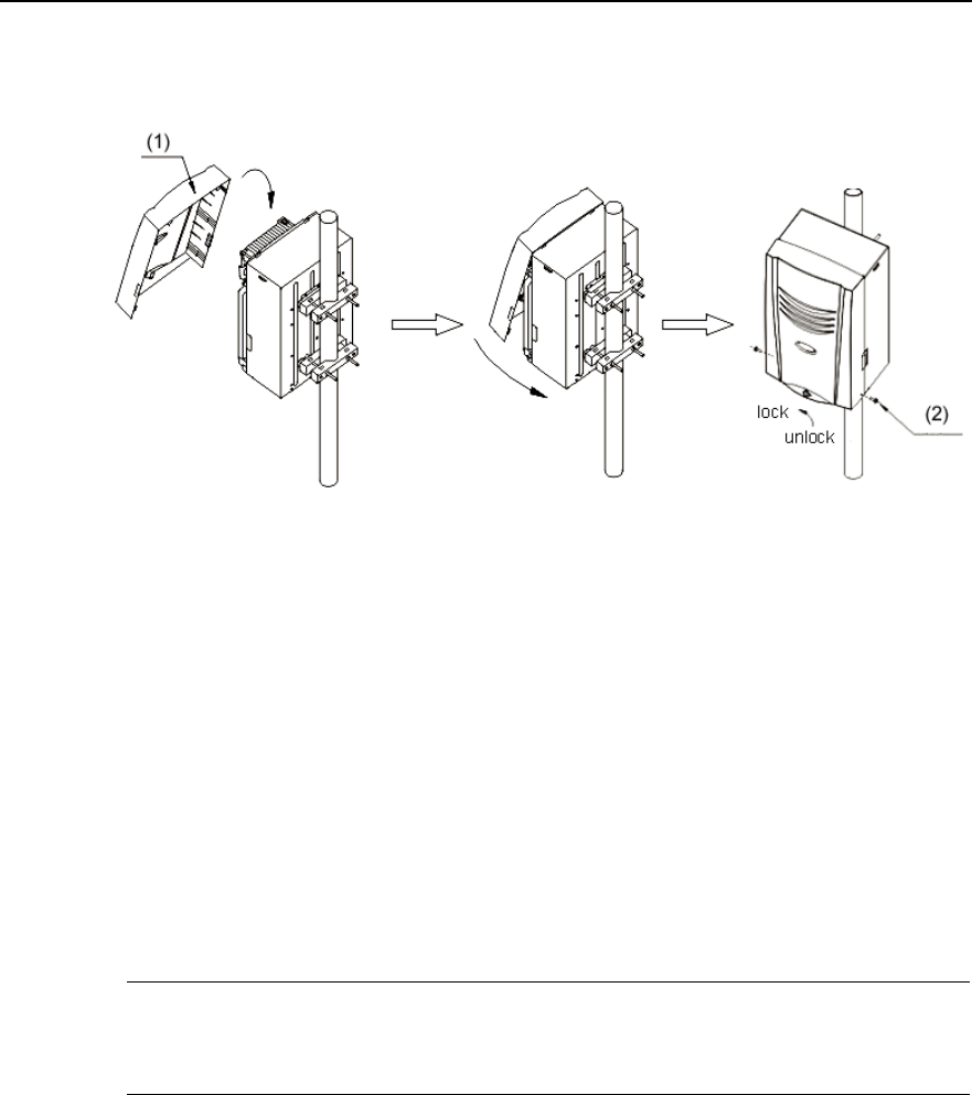
Installation Manual
iSiteC BTS3601C CDMA Base Station Hardware Installation
2 Installing Cabinet Hardware
2-31
3) Get them locked.
Figure 2-31 shows the whole installation.
1) Plastic shell 2) Bolt
Figure 2-31 Installing the shell
2.3.8 Installing Sun-shading Cover
If the BTS3601C is located outdoors, the sun-shading cover should be installed. The
cover should be installed above the BTS3601C and fixed onto the same metal mast
with the BTS3601C via metal holding hoops. The bottom of the cover should be
50~100mm away from the top of the BTS3601C. Method to install the cover is almost
the same with that to install the BTS3601C rack onto metal masts. Please refer to
contents related.
&
Note:
Sun-shading cover is optional according to the actual environment of the site.
2.4 Installing Auxiliary Equipment
Auxiliary equipment includes IAFB, AC lightning protection box, the IABB, UPS, etc. In
different projects, different auxiliary equipment will be adopted. Following are to
introduce the methods to install certain auxiliary equipment first, then the methods to
connect their cables in terms of different projects.
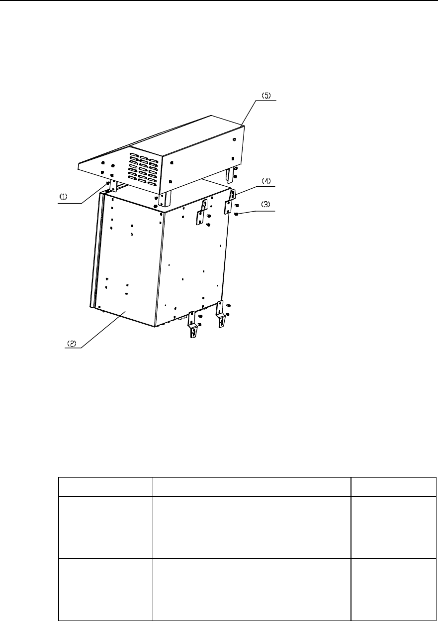
Installation Manual
iSiteC BTS3601C CDMA Base Station Hardware Installation
2 Installing Cabinet Hardware
2-32
2.4.1 Installing IAFB
IAFB provides the BTS3601C with certain auxiliary functions and integrates most of the
auxiliary equipment inside a box. Figure 2-32 shows the appearance of an IAFB.
1) M6%12 bolt 2) Box 3) M6%12 bolt 4) Hanger 5) Sun-shading cover
Figure 2-32 IAFB appearance
IAFB comprises two types: One applies to southern environment and the other to
northern environment. Table 2-1 shows their respective configurations.
Table 2-1 IAFB description
IAFB type Configuration Applicable Scope
One applying to southern
environment
AC lightning protection box
Power module for transmission
Various lightning arresters for transmission
Various power distribution terminals and air switches
Optical Distribution Frame (ODF) \Digital Distribution
Frame (DDF)
Applicable to various
envrionment
One applying to northern
environment
AC lightning protection box
Power module for transmission
Various lightning arresters for transmission
Various power distribution terminals and air switches
ODF\DDF
Hot plate
Applicable to cold
areas
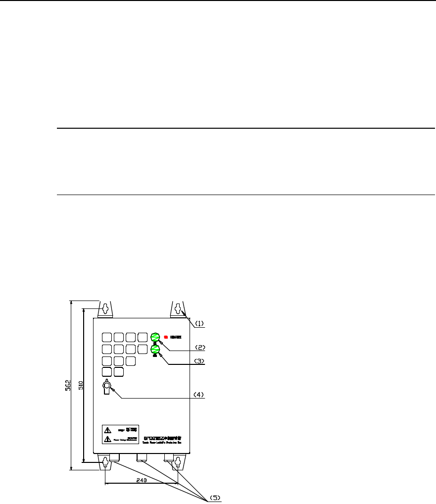
Installation Manual
iSiteC BTS3601C CDMA Base Station Hardware Installation
2 Installing Cabinet Hardware
2-33
Three modes are available to install an IAFB, namely, intalling it on walls, metal masts
(with the diameter v60~v114) or poles (with the diameter v150~v350). The detailed
installation procedures are available in Appendix A.
2.4.2 Installing AC Lightning Protection Box
&
Note:
In terms of its discharging currents, the AC lightning protection box can be classified into three types: 20kA,
40kA and 100kA. All boxes mentioned in this chapter are of 20kA.
I. Structure
AC lightning protection box prevents the AC input power supply from lightning strikes.
Its appearance is shown in Figure 2-33.
1) Hanger 2) RUN indicator 1 3) RUN indicator 2
4) Door lock 5) Cabling hole
Figure 2-33 AC lightning protection box appearance
There are two indicators on the door of the box. The significance of two indicators
depends on the positions of the air switch inside the box. If the switch is off, the
indicators run normally. Otherwise, the indicators will be both off, and the lightning
protection box will be invalid. Table 2-2 shows the meanings of indicator statuses.
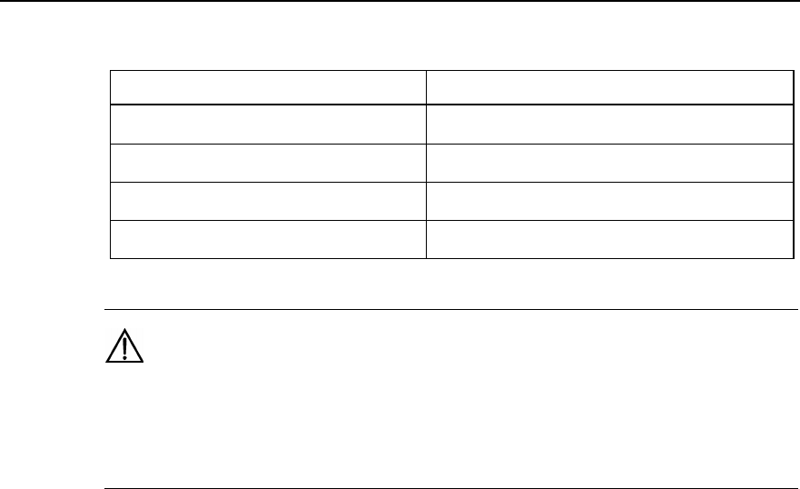
Installation Manual
iSiteC BTS3601C CDMA Base Station Hardware Installation
2 Installing Cabinet Hardware
2-34
Table 2-2 Meanings of AC lightning protection box indicators
RUN indicator status Meaning
RUN indicator 1: On;
RUN indicator 2: On. Lightning protection function normal
RUN indicator1: Off;
RUN indicator2: On C-level lightning protection function disabled
RUN indicator 1: On;
RUN indicator 2: Off D-level lightning protection function disabled
RUN indicator 1: Off;
RUN indicator 2: Off Lightning protection function disabled (except for the
interruption of external power supply)
Caution:
If either of the two RUN indicators is off, it indicates that the lightning protection box runs abnormally.
Please contact Huawei engineers at once. Otherwise the related equipment may suffer from lightning
strikes.
II. Method
Three modes are available to install an IAFB, namely, intalling it on walls, metal masts
(with the diameter v60~v114) or poles (with the diameter v150~v350).
III. Installation flow
Figure 2-34 shows the installation flow of AC lightning protection box.
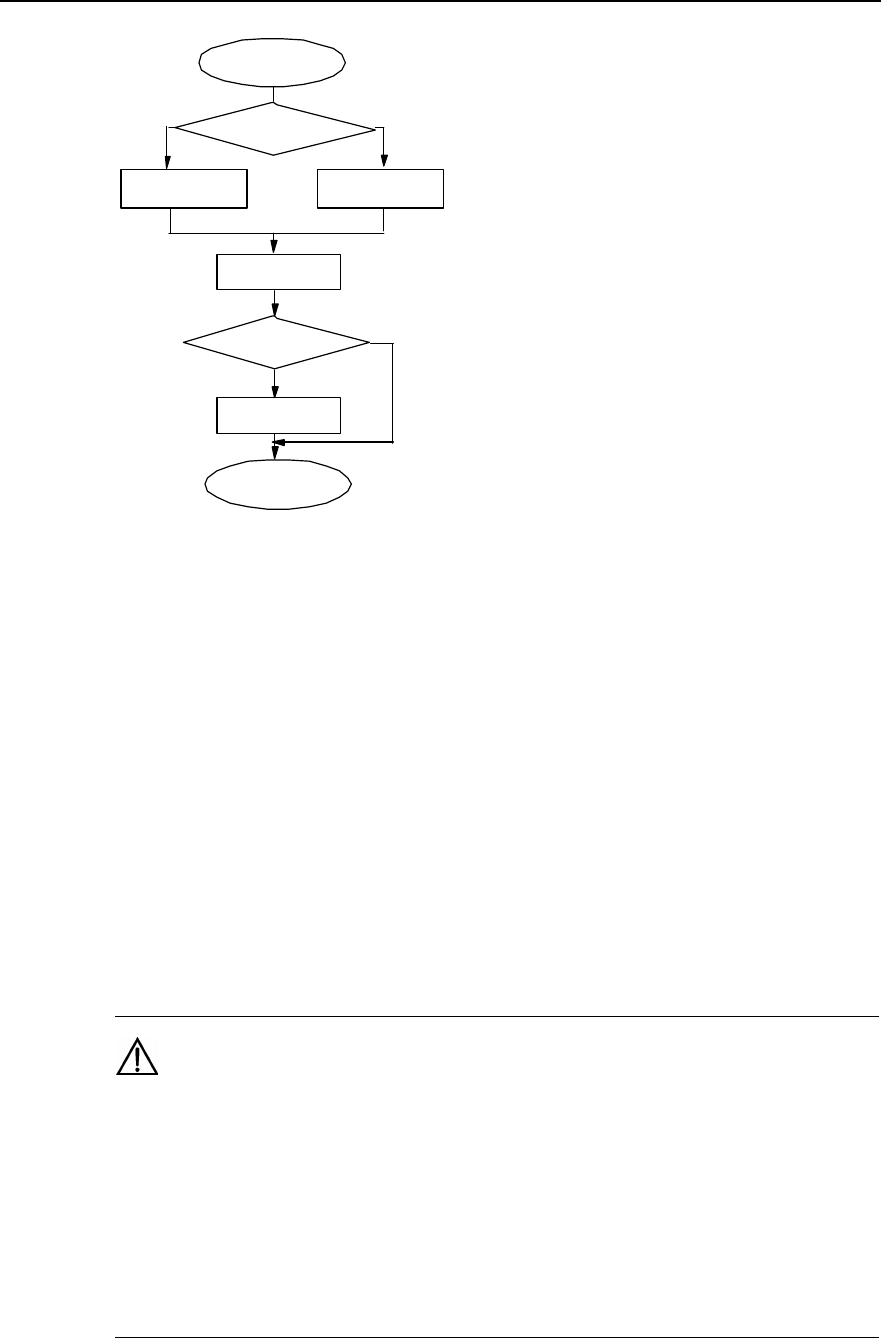
Installation Manual
iSiteC BTS3601C CDMA Base Station Hardware Installation
2 Installing Cabinet Hardware
2-35
Start
Install AC lightning
protection box
Install sun-
shading cover
End
Wall
installation Metal mast or pole
installation
Install fastenerInstall bolts
Outdoor
installation?
Y
N
Select installation
mode
Figure 2-34 Installation flow of AC lightning protection box
IV. Procedures
Installing the box on wall
1) Put the lightning protection box against the wall and mark the positions where the
four expansion bolts are to be installed. The sizes of holes for expansion bolts are
shown in Figure 2-33.
2) Drll holes with a percussion drill (drill bit v10) at the marked position on the wall.
After the drilling, remove the dust inside and outside the holes with a vacuum
cleaner, and then check the distance among the holes. Whenever big errors occur,
the relevant hole must be relocated and drilled again.
Caution:
1) Hold the drilling bit vertical to the wall during drilling. Hold tight the drillstock with two hands to keep it in
the right direction, as vibrations may lead to damaged wall and the hole not straight.
2) The hole depth should be the length of the expansion bolt sleeve plus the drill bit. The hole depths of
respective holes should be consistent. Before measuring the hole depth, remove the dust inside the hole
and measure the hole depth. Remove the dust with a vacuum cleaner before drilling.
3) If the wall is too hard and smooth to settle the drill bit, punch a pit with a chisel to help positioning the
hole.
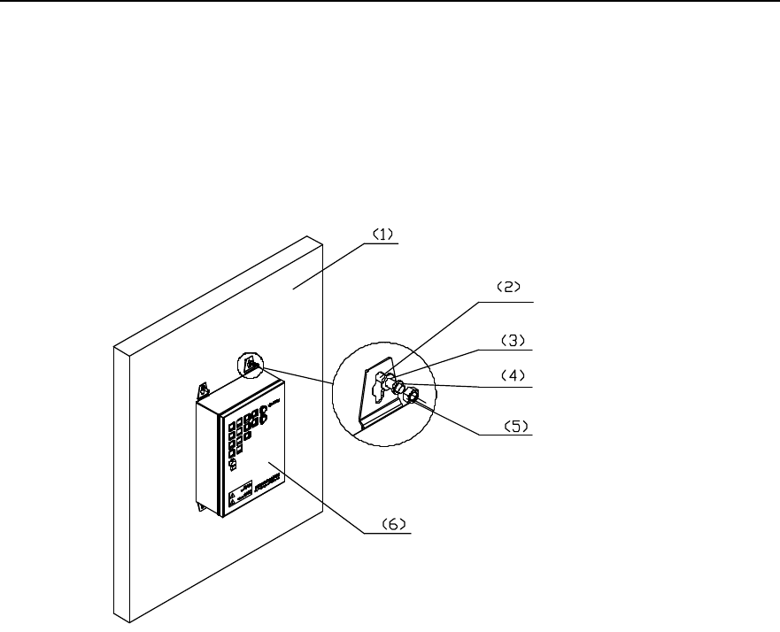
Installation Manual
iSiteC BTS3601C CDMA Base Station Hardware Installation
2 Installing Cabinet Hardware
2-36
3) Unfix the washer and nut from the expansion M8%80 bolt, put the expansion bolt
and the expansion sleeve vertically into the hole and strike the bolt with a rubber
hammer until the expansion sleeve is completely driven in the hole.
4) Pull the four expansion bolts through the four hangers of the box.
5) Put the plain washers, spring washers, and nuts onto the exapnsion bolts, revise
the location of the box, and tighten the nuts to a torque of 13.4 N$m. Figure 2-35
shows the whole process.
1) Wall 2) M8%80 expansion bolt 3) Plain washer 8
4) Spring washer 8 5) Nut M8 6) AC lightning protection box
Figure 2-35 Fixing AC lightning protection box (on wall)
6) If a sun-shading cover (applicable to outdoor AC lightning protection box) is
necessary, please align the installation holes of the cover with the upper two
expansion bolts, then in turn put plain washers, spring washers and nuts onto the
expansion bolts, and then revise the location of the box, finally, tighten the nuts to
a torque of 13.4 N$m. Figure 2-36 shows the process.
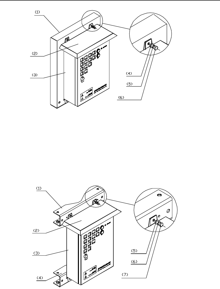
Installation Manual
iSiteC BTS3601C CDMA Base Station Hardware Installation
2 Installing Cabinet Hardware
2-37
1) Wall 2) Sun-shading cover 3) AC lightning protection box
4) Plain washer 8 5) Spring washer 6) Nut M8
Figure 2-36 Installing sun-shading cover for AC lightning protection box
Installing the box on metal mast:
1) Fix the AC lightning protection box, sun-shading cover, and beam together with
M8%25 expansion bolts, spring washers, and plain washers, as shown in Figure
2-37.
1) Beam 2) Sun-shading cover 3) AC lightning protection box 4) Beam
5) Plain washer 8 6) Spring washer 7) M8%25 expansion bolt
Figure 2-37 Fixing the box on beams
2) Put the fixed beam and the box against the metal mast, intall the fasteners and
place the mast on the middle of the beam and the fastener. Then pull the M10 bolt
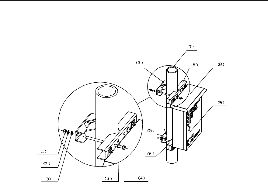
Installation Manual
iSiteC BTS3601C CDMA Base Station Hardware Installation
2 Installing Cabinet Hardware
2-38
througth the beam and the fastener, put plain washers, spring washers and nuts
onto the bolt and tighten the nut to a torque of 26.5 N$m with a spanner. The
process is shown in Figure 2-38.
1) Nut M10 2) Spring washer 10 3) Plain washer 10
4) M10 bolt 5) Fastener 6) Beam
7) Metal mast 8) Sun-shading cover 9) AC lightning protection box
Figure 2-38 Fixing AC lightning protection box (on metal masts)
Installing the box on pole
1) Fix the box, flashing board and the beam together with M8%25 bolts, spring
washers, plain washers, as shown in Figure 2-37.
2) Place the fixed beam and the box together against the pole. At the other side of the
pole, install another beam and get the pole at the middle between two beams.
Then pull the M12 bolts through the two beams, put plain washers, spring washers
and nuts onto the bolts, and tighten the nuts to a torque of 45 N$m with a spanner,
as shown in Figure 2-39. If the pole is a little bit thin, cut the exposed bolts to keep
the length of the exposed part about 20mm.
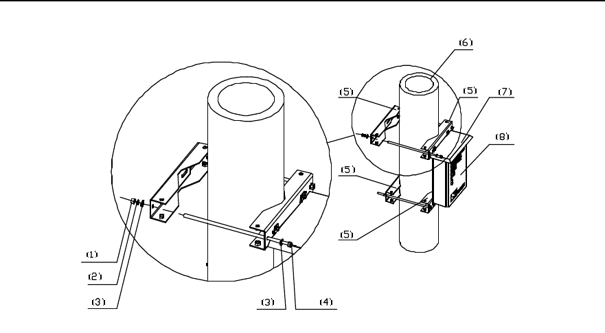
Installation Manual
iSiteC BTS3601C CDMA Base Station Hardware Installation
2 Installing Cabinet Hardware
2-39
1) Nut M12 2) Spring washer 12 3) Plain washer 12 4) M12 bolt
5) Beam 6) Pole 7) Sun-shading cover 8) AC lightning protection box
Figure 2-39 Fixing AC lightning protection box (on pole)
2.4.3 Installing UPS
Generally, there are four modes to install a UPS, i.e. on ground base, wall, metal mast
(with the diameter of v60~v114) or pole (with the diameter of v150~v350).
The detailed installation method of UPS is available in the installation guide of the UPS
supplier.
2.4.4 Installing IABB
I. Structure
The box provents the backup battery groups of BTS3601C from being damaged so as
to provide the BTS3601C with backup power. Its structure is similar to that of
BTS3601C and IAFB.
Inside the box, 6 batteries can be installed. When the box is used independently, only
two batteries are used generally. When the box works together with the UPS, the 6
batteries of it are used. Following are the technical items of the battery:
l Voltage rating of a battery is 12V. When 6 batteries are in series, the voltage rating
is 72V.
l Capacity rating: 26Ah.
l Work temperature: -15°C~+45°C
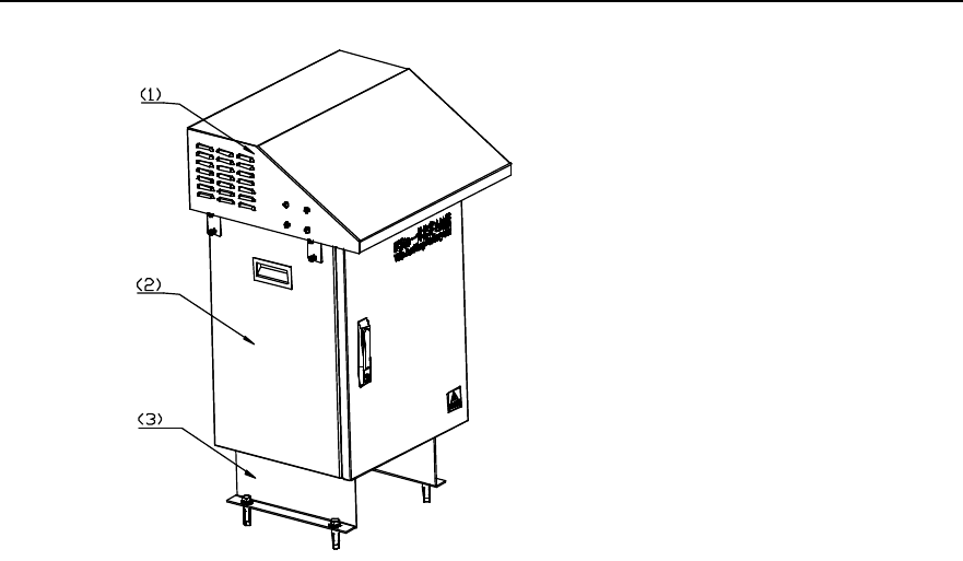
Installation Manual
iSiteC BTS3601C CDMA Base Station Hardware Installation
2 Installing Cabinet Hardware
2-40
1) Sun-shading cover 2) Box 3) Support
Figure 2-40 IABB appearance
II. Method
The box can be installed on the concrete floor or metal platform, instead of on holding
support or wall.
III. Installation flow
Figure 2-41 shows the installation flow of the IABB.
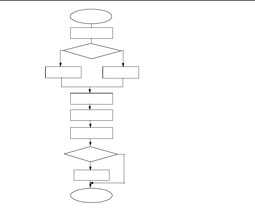
Installation Manual
iSiteC BTS3601C CDMA Base Station Hardware Installation
2 Installing Cabinet Hardware
2-41
Start
Concrete ground
installation Steel workbench
installation
Install support
Fix box
Install sun-
shading cover
End
Drill holes on
concrete ground
Drill holes on steel
workbench
Outdoor
insdtallation?
Y
N
Install expansion
bolts
Install batteries and
connect cables
Select installation
mode
Figure 2-41 Installation flow of the IABB
IV. Procedures
Installing the box on concrete floor:
1) Install the fixing support onto the battery box via 4 M12%20 assembling bolts, as
shown in Figure 2-42.
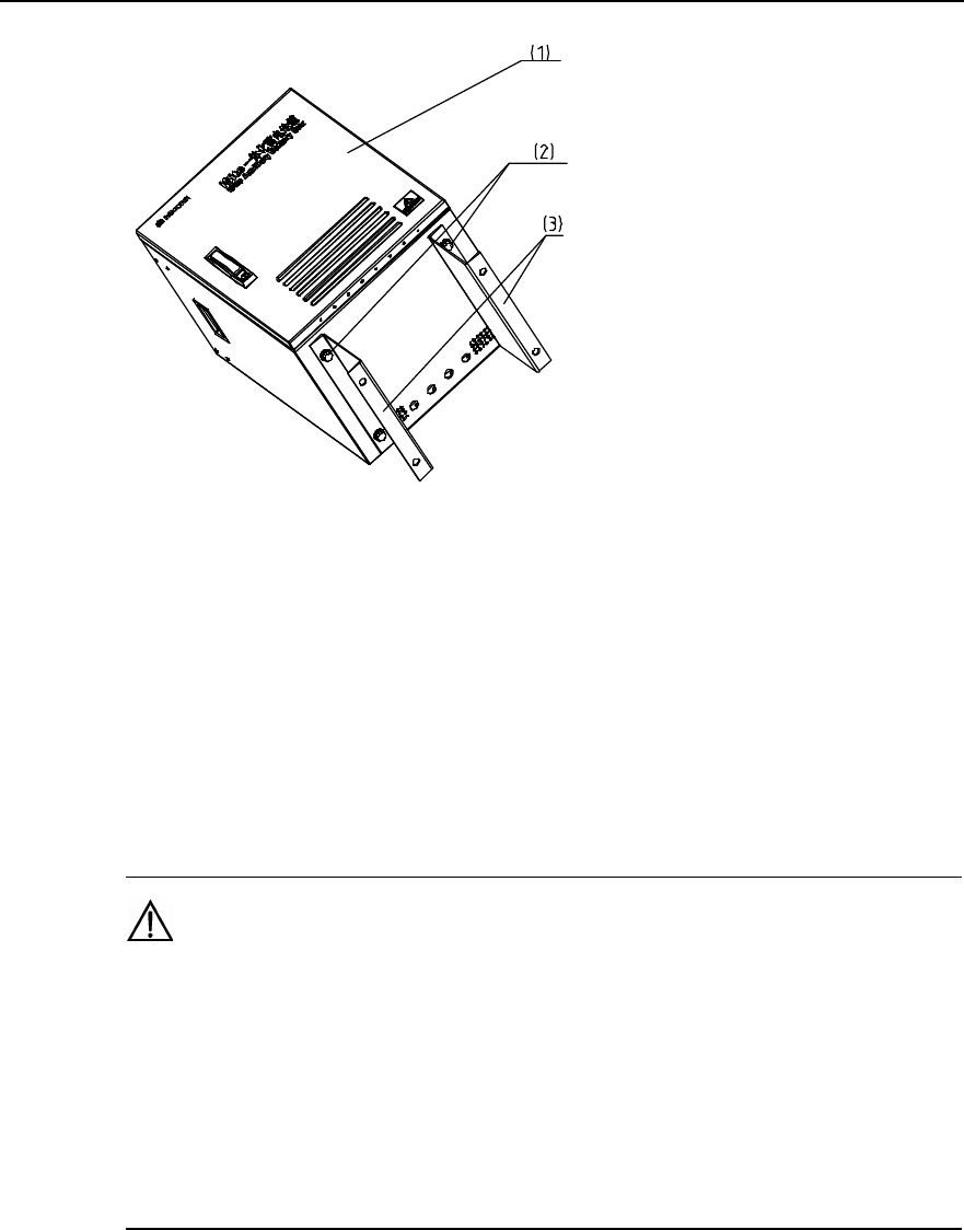
Installation Manual
iSiteC BTS3601C CDMA Base Station Hardware Installation
2 Installing Cabinet Hardware
2-42
1) Box 2) M12%20 bolt, spring washer, plain washer 3) Fixing support
Figure 2-42 Installing the fixing support
2) Place the box onto the floor and mark the places on the floor where all 4
connection holes on the support are located.
3) Drill holes on the floor via a percussion drill with the drill bit of v16. After the drilling,
remove the dust inside and outside the holes with a vacuum cleaner, and then
check the distance among the holes. Whenever big errors occur, the relevant
holes must be relocated and drilled again.
Caution:
1) Hold the drilling bit vertical to the floor during drilling. Hold tight the drillstock with two hands to keep it in
the right direction, as vibrations may lead to damaged floor and the hole not straight.
2) The hole depth should be the length of the expansion bolt sleeve plus the drill bit. The hole depths of
respective holes should be consistent. Before measuring the hole depth, remove the dust inside the hole
and measure the hole depth. Remove the dust with a vacuum cleaner before drilling.
3) If the floor is too hard and smooth to settle the drill bit, punch a pit with a chisel to help positioning the
hole.
4) Unfix the spring washer, nut and plain washer. Put the expansion bolt into the hole
and knock directly on the bolt with a hammer (such as nail hammer) until the bolt is
completely driven into the floor. Then, put the nut on the bolt and tighten it until the
bolt is expanded slightly so as to avoid it getting loose.
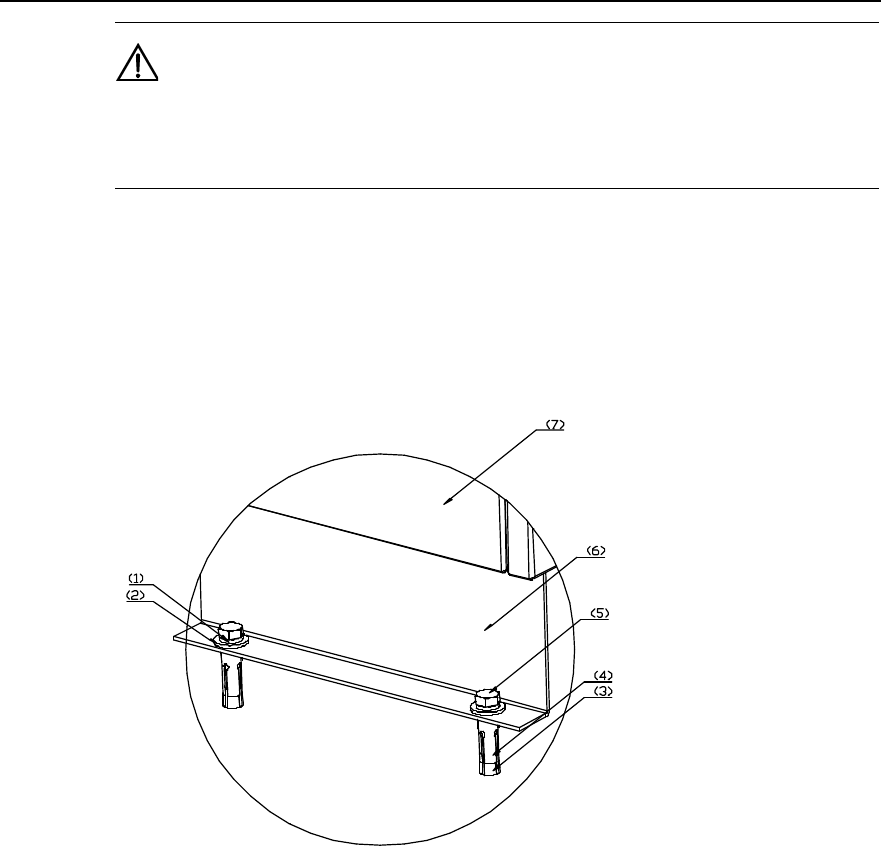
Installation Manual
iSiteC BTS3601C CDMA Base Station Hardware Installation
2 Installing Cabinet Hardware
2-43
Caution:
The proper length of the hole should be 55mm~65mm. Otherwise, the expansion bolt cannot be
completely driven into the hole, which affects the reliability of the box.
5) Put in turn spring washers, and plain washers onto 4 M12%60 bolts, and pull 4
bolts through the holes at the bottom of the support, then put expansion sleeves
and nuts onto the bolts. And then put the bolts into the holes made on the concrete
floor and tighten the bolts with a spanner, as shown in Figure 2-43. Therefore, the
box is secured on the floor.
1) Spring washer 2) Plain washer 3) Expansion bolt 4) Expansion sleeve
5) Bolt 6) Support 7) Box
Figure 2-43 Fixing the box onto the concrete floor
6) Open the door of the box and place the batteries into the box. The box comprises
three layers, each of which can hold two batteries.
7) Connect 6 batteries in series via the cables delivered with the box, as shown in
Figure 2-44.
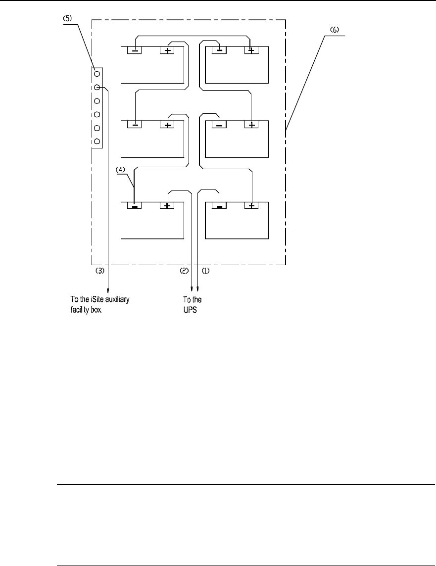
Installation Manual
iSiteC BTS3601C CDMA Base Station Hardware Installation
2 Installing Cabinet Hardware
2-44
1) UPS with power cable (negative cable) 2) UPS with power cable (positive) 3) Grounding cable
4) Battery cable 5) PGND bar in the battery box 6) Battery box
Figure 2-44 Connecting UPS to the IABB
8) Check whether the voltage of battery groups are over 72V with a multimeter. If Yes,
it indicates the installation is OK. Otherwise, errors exist in the installation. Check
the polarities of the batteries and make sure they are OK. If the errors still cannot
be located and the voltage is lower than 72V, it indicates errors exist in the battery
cables or batteries themselves. Please contact Huawei engineers.
&
Note:
When the IABB is used without being connected to a UPS, only two batteries are used generally. The
corresponding internal connection is shown in Figure 2-45. After the connection, it is still required to check
the voltage (24V or not) of the battery group via a multimeter, so as to ensure the connection is correct.
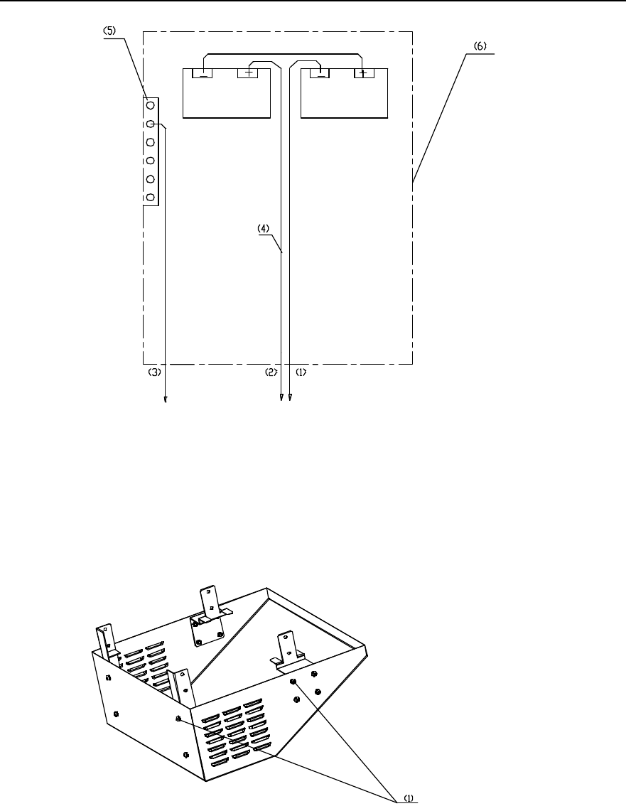
Installation Manual
iSiteC BTS3601C CDMA Base Station Hardware Installation
2 Installing Cabinet Hardware
2-45
To the UPS
To the iSite Auxiliary
Facility Box
1) UPS with power cable (negative cable) 2) UPS with power cable (positive cable) 3) Grounding cable
4) Battery cable 5) PGND bar in the battery box 6) Battery box
Figure 2-45 Internal connection of the IABB (without UPS)
9) Secure the support of the sun-shading cover with M6%12 assembling bolts, as
shown in Figure 2-46.
1) M6%12 assembling bolt
Figure 2-46 Installing sun-shading cover
10) Install the sun-shading cover onto the box, as shown in Figure 2-47.
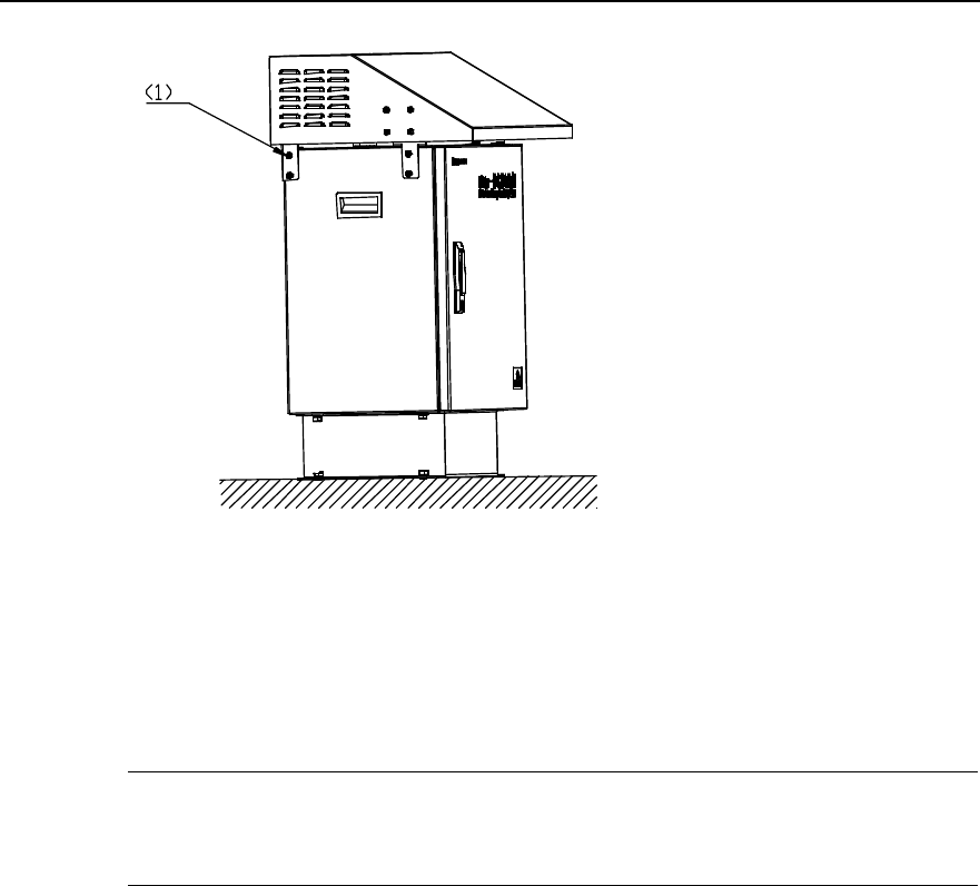
Installation Manual
iSiteC BTS3601C CDMA Base Station Hardware Installation
2 Installing Cabinet Hardware
2-46
1) M6%12 assembling bolt
Figure 2-47 Fixing the sun-shading cover
Installing the box on steel platform:
&
Note:
Procedure to install the box on steel platform is similar to that on concrete floor.
1) Install the fixing support onto the battery box via 4 M12%20 assembling bolts, as
shown in Figure 2-42.
2) Place the box on the platform and mark positions on the platform for all 4
connection holes in the fixing support.
3) Drill holes using a percussion drill with the bit of v16. After the drilling, remove the
dust inside and outside the holes with a vacuum cleaner, and then check the
distance among holes. Whenever big errors occur, the relevant holes must be
relocated and drilled again.
Installation Manual
iSiteC BTS3601C CDMA Base Station Hardware Installation
2 Installing Cabinet Hardware
2-47
Caution:
1) Hold the drilling bit vertical to the platform during drilling. Hold tight the drillstock with two hands to keep
it in the right direction, as vibrations may lead to damaged platform and the hole not straight.
2) The hole depth should be the length of the expansion bolt sleeve plus the drill bit. The hole depths of
respective holes should be consistent. Before measuring the hole depth, remove the dust inside the hole
and measure the hole depth. Remove the dust with a vacuum cleaner before drilling.
3) If the platform is too hard and smooth to settle the drill bit, punch a pit with a chisel to help positioning the
hole.
4) Unfix the spring washer, nut and plain washer. Put the expansion bolt into the hole
and knock directly on the bolt with a hammer (such as nail hammer) until the bolt is
completely driven into the hole. Then, put the nut on the bolt and tighten it until the
bolt is expanded slightly so as to avoid it getting loose.
Caution:
The hole depth should be big enough (55mm~65mm); otherwise, the expansion bolts cannot be
completely driven into the holes, which may affect the reliability of the box.
5) Put in turn spring washers and plain washers onto the 4 M12%60 bolts, and pull the
bolts through the holes at the bottom of the support then through the holes made
at the bottom of the platform. Put washers and nuts onto the bolt, and tighten the
nuts reliably with a spanner.
6) Method to install the sun-shading cover is the same as that mentioned in
"Installing the box on concrete floor".
2.5 Installing Cables
During the installation of BTS3601C major equipment, the cables (excluding feeders)
at the BTS3601C side have been distributed. Following is to introduce the cable
connections between major equipment and auxiliary equipment, and those among
auxiliary equipment in terms of varied networking modes. The installation of feeders is
covered in Chapter 3.
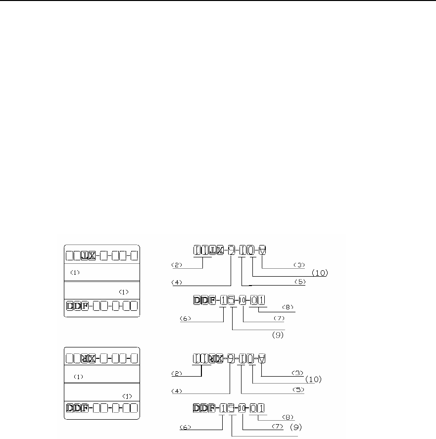
Installation Manual
iSiteC BTS3601C CDMA Base Station Hardware Installation
2 Installing Cabinet Hardware
2-48
2.5.1 Cable Connection Requirements
I. For trunk cables
1) Gists for indoor installation
l Trunk cables should not be cross-connected with power cable and RF jumper.
l When trunk cables are distributed along iron objects and poles, they must be
protected by currgated cabling trough. The trough should be secured onto the wall
with wall fixing clips. And the cables should be distributed horizontally and straight.
If the turns of cables are unavoidable, the minimum angles at the turns should not
be smaller than 120°.
2) Trunk cables must be labeled after connection. The label appearance and filling
format is shown in Figure 2-48. Please strictly follow the format for the
convenience of future maintenance.
1) Trunk cable label 2) E1 No. 3) Row No. 4) Slot No. (0~1)
5) Subrack No. 6) Row No. 7) Line No. 8) E1 No. (on DDF)
9) Column No. 10) Column No.
Figure 2-48 Appearance and filling format for 75W trunk cable labels
3) Gists for outdoor installation
l If the transmission equipment is located on the same platform with the BTS3601C,
transmission cables must be protected by currgated tubes, which should be fixed
with black ties. And cables should be distributed horizontally and straight, and
smoothly via circular arcs at the turns.
l If transmission equipment does not share the same platform with the BTS3601C,
the transmission cable between them need to be distributed in air. So double
shielded cable should be adopted with both ends of the external cable grounded
and connected to the grounding cable at the BTS3601C side, then to the
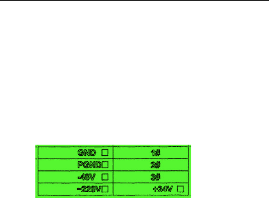
Installation Manual
iSiteC BTS3601C CDMA Base Station Hardware Installation
2 Installing Cabinet Hardware
2-49
grounding busbar. If no double shielded cable is avaialble, the transmission cables
must wear the 50m-long metal tubes. And both ends of the tube should be
grounded.
l Trunk cable should be labeled after the distribution.
II. For power cables
1) Gists for indoor installation
l Power cables should not be cross-connected or in parallel with signal cables.
l Cables distributed on the wall must be protected by PVC cabling trough, which
should be fixed on the wall with wall fixing clips. And cables should be distributed
horizontally and straight. Even if turns are unavoidable, the minimum angle at
each turn should not be smaller than 120°.
l Power cables should be labeled after the connection. Figure 2-49 shows the
appearance of a power cable label.
Figure 2-49 Power cable label appearance
2) Gists for outdoor installation
l It is strongly prohibited to tie AC power cable on the iron objects and then lead it
into BTS3601C. Instead, the cable should be first connected to porcelain insulator,
then to BTS3601C.
l Power cables distributed along the iron object and pole must be protected by
currgated tubes, as well as the transmission cables. The tubes should be fixed
with black ties. Cables should be distributed as horizontally and straight as
possible. If turns of cables are unavoidable, the turns should be be made smoothly
via circular arcs.
III. For grounding cables
As the requirements for grounding cable connections are comparatively complicated.
Following is to describe them in terms of varied installation modes.
1) Installing BTS3601C on tower
l The grounding of BTS3601C system and tower lightning protection system must
share the same grounding body.
l When the BTS3601C is close to the transformer for power distribution (straight
distance less than 30m), the counterpoise of the BTS3601C system should be
connected to that of the transformer and form a unified counterpoise.

Installation Manual
iSiteC BTS3601C CDMA Base Station Hardware Installation
2 Installing Cabinet Hardware
2-50
l When an independent grounding busbar is adopted for the BTS3601C, it should
be installed on the tower directly without any insulation processing. The grounding
busbar of the BTS3601C should have the dedicated grounding downlead made of
40%4mm hot-gavanlizing flat steel. The PGND bar should be connected or welded
to the grounding downlead via 35mm2 yellow-green plastic insulation copper core
wire. The downlead should not be insulated from the tower body.
2) Installing BTS3601C on poles
l The PGND of BTS3601C system should share the same grounding body with the
lightning protection grounding of poles.
l When the BTS3601C is close to the transformer for power distribution (straight
distance less than 30m), the counterpoise of the BTS3601C system should be
connected to that of the transformer so as to form a unified counterpoise.
l The overlapped parts of the metal fixing beam (between the two poles) and the
downlead of the lightning arrester should be soldered together reliably. Various
equipment is installed on the metal holding support between fixing beams (the
support is soldered on the beams). The mechnical parts of all equipment should
contact the metal holding support directly without any insulation processing.
Full-length welding should be adopted here, instead of dot welding, as the latter is
unreliable.
l The overlapped parts between the metal fixing parts of the platform and the
downleads of the two lightning arresters should be reliably welded together. Or,
instead, a 40%4mm hot-galvanizing flat steel should be installed on the platform.
The two ends of the steel should be welded to the bench and the middle part of the
steel to the downleads of arresters. If the platform and the downleads of arresters
have not be welded together when the concrete pole is set up, connect them via
35mm2 yellow-green protection grounding cable and the grounding clip that
connects the flat steel to the OT. Full-length welding should be adopted here,
instead of dot welding, as the latter is unreliable.
l Cabling ladder should be installed and fixed via metal fixing beam between two
poles for antenna feeders. Good electric connection should be achieved between
the cabling ladder and the fixing beam. Meanwhile, the overlapped parts of the
fixing beam and the downlead of the lightning arrester should be welded together.
l BTS3601C grounding busbar should be installed directly on metal holding support
or platform without any insulation processing. A dedicated grounding downlead
(made of 40%4mm hot-galvanizing flat steel) should be prepared for the grounding
busbar. BTS3601C grounding busbar should be connected to the grounding
downlead via 35mm2 yellow-green plastic insulation copper wire or be welded with
it. And the downlead should not be insulated from various metal parts between the
two poles.
l Installing BTS3601C on metal mast of building-top
l The PGND of BTS3601C system should share the same grounding body with the
lightning protection grounding of the metal mast on building-top.

Installation Manual
iSiteC BTS3601C CDMA Base Station Hardware Installation
2 Installing Cabinet Hardware
2-51
l If the building containing the BTS3601C is close (straight distance less than 30m)
to the transformer for power distribution, the counterpoise of the building should be
connected to that of the transformer and form a unified counterpoise.
l BTS3601C grounding busbar should be installed together with the BTS3601C
directly on the metal mast without any insulation processing. At the same time, a
grounding cable should be led from the metal mast to the BTS3601C grounding
busbar, be fixed via bolts or be welded onto the metal mast. It should be made of
yellow-green plastic insulation copper wire with the core diameter not less than
16mm2. Or, instead, a piece of 40%4mm hot-galvanizing flat steel should be
welded onto the mast and the wire hole should be reserved on the other end of the
steel, so as to connect grounding cable to the BTS3601C grounding busbar.
l If grounding bar or grounding point is available in the building-top or inside the
building (e.g. the PGND bar of the communication euipment room), the downlead
of the BTS3601C grounding busbar should be connected directly to the grounding
bar available on building-top or inside the building. The grounding downlead
should be made of yellow-green plastic insulation copper wire with the core
diameter not less than 35mm2.
l If no grounding point is available inside the building, the downlead of the
BTS3601C grounding busbar should be led down to the building bottom and
connected to the counterpoise of the building. The downlead should be made of
40%4mm hot-galvanizing flat steel or yellow-green plastic insulation copper wire
with the core diameter not less than 35mm2.
3) Installing BTS3601C indoors
l If the equipment room is close (straight distance less than 30m) to the transformer
for power distribution, the counterpoise of the equipment room should be
connected to that of the transformer so as to form a unified counterpoise.
l If PGND bar is available inside the equipment room, the grounding busbar of the
BTS3601C system should be connected via PGND cable to the grounding bar of
the equipment room directly. The grounding cable should be made of 35mm2
yellow-green plastic insulation copper wire.
l If PGND bar is available in other rooms (e.g. communication equipment room in
the building) instead of the equipment room, the downlead of the BTS3601C
grounding busbar should be connected to the grounding bar in such room. The
grounding downlead should be made of yellow-green plastic insulation copper
wire with the core diameter not less than 35mm2. If no groundign point is available
in the whole building, the downlead may be led down to the bottom of the building
then to the counterpoise of the building. The grounding downlead should be made
of yellow-green plastic insulation copper wire with the core diameter not less than
35mm2.
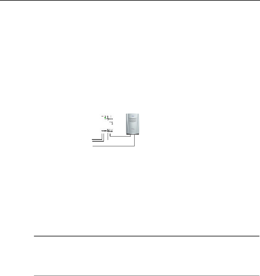
Installation Manual
iSiteC BTS3601C CDMA Base Station Hardware Installation
2 Installing Cabinet Hardware
2-52
2.5.2 Networking of AC Lightning Protection Box
I. Plan without the IABB
Figure 2-50 shows the connection between the BTS3601C and an independent AC
lightning protection box.
220VAC BTS3601C 220VAC input cable
BTS3601CAC lightning protection box
A pair of fiber cables or E1 cable
Grounding cable
Figure 2-50 Networking of AC lightning protection box (20kA, without the IABB)
&
Note:
In terms of its discharging currents, the AC lightning protection box can be classified into three types: 20kA,
40kA and 100kA. All boxes mentioned in the chapter are of 20kA.
Three cables are used for the external connection of the AC lightning protection box:
1) External power supply input cable
It is a twin-core cable (L, N). When AC power is led into the box via this cable, the live
wire is connected to the "L" end and the neutral wire to the "N" end.
The cable is provided by user and the ends of the cable can be distinguished via a
multimeter, i.e. the one with lower voltage is "N" end, and the higher one is "L" end.
2) Cable connecting the box to the BTS3601C
It is a complete three-core cable (L, N, and PE). The port at BTS3601C side is a round
waterproof connector which has been installed during the instllation of major equipment.
The output interface of the lightning protection box is an air switch. When connecting
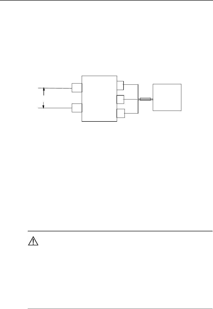
Installation Manual
iSiteC BTS3601C CDMA Base Station Hardware Installation
2 Installing Cabinet Hardware
2-53
this cable, directly take off the cover of the cable and insert the copper-core wire into
the switch.
In terms of its appearance, if the cable comprises three wires, black one, white one and
yellow-green one, the black is L end, the white is N end, and the last one is PGND wire.
If it is made of coffee, blue, and yellow-green wires, the coffee wire is the L, the blue
wire is the N, and the last one is PGND wire.
Figure 2-51 shows the connection.
LL
N
N
PE
220VAC BTS3601C
AC lightning
protection box
Figure 2-51 Cable connection of AC lightning protection box networking (without UPS)
3) Grounding cable of the AC lightning protection box
Inside the box, there is a grounding bar. If the AC power cable carries PGND cable (PE
wire), the PGND cable should be grounded together with the PGND of the BTS3601C
system. The PE wire should be connected directly to the grounding bar of the box.
AC lightning protection box should have a PGND, and the PGND cable should be made
of yellow-green plastic insulation copper wire with the core diameter not less than
16mm2. The length of the PGND cable connecting to the BTS3601C grounding busbar
should be less than 1m.
Caution:
1) Generally, the only power cable provided by Huawei together with the BTS3601C is 3m. Users are
required to prepare the extra cable if it is not long enough.
2) The external AC power cable to the BTS3601C should be connected to the AC lightning protection box.
It is not allowed to connect the external power cable to the terminal for power distribution in the IAFB first,
then to the AC lightning protection box.
3) Above principles for cable connection are also applicable to the IAFB (with AC lightning protection box
built-in).
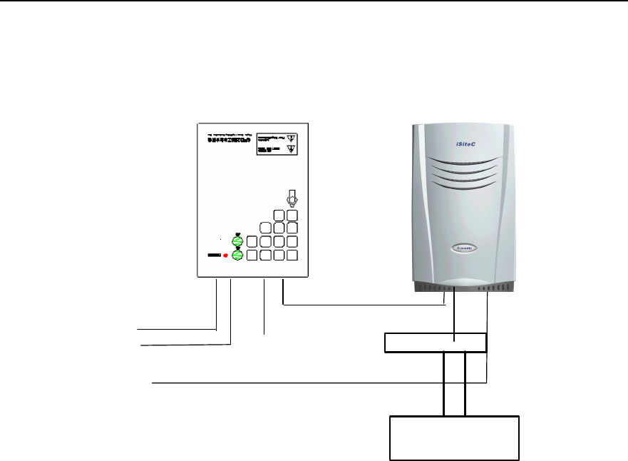
Installation Manual
iSiteC BTS3601C CDMA Base Station Hardware Installation
2 Installing Cabinet Hardware
2-54
II. Plan with the IABB
Figure 2-52 shows the connection in this networking mode.
220VAC
BTS3601C 220VAC Input cable
BTS3601C
AC lightning protection box
A pair of fiber cables or E1 cable
Commutator
+24V GND
Grounding cable
IABB
Figure 2-52 Networking of AC lightning protection box (20kA, with the IABB)
In this plan, the cable connection of AC lightning protection box is completely the same
as that of the IABB. Following is to describe the cable connection between the IABB
and the BTS3601C.
1) Cable connection between IABB and BTS3601C
Two cables are led out from the IABB. One is of +24V and red, and the other is of GND
and black. Two cables are connected to the DC power cable of the BTS3601C through
a commutator. The +24V cable is interconnected to the red one of the BTS3601C DC
power cable through the red plug of the commutator; and the blcak GND cable is
interconnected to the black one of the BTS3601C power cable through the black pulg of
the commutator. After their interconnections, three types of tapes should be used for
the waterproof of the connections. The detailed processing is available in Section 2.3.6.
2) Grounding of the IABB
The battery box is generally installed on the platform. In this case, the metal shell of the
box should be grounded, and the PGND wire should be connected to the BTS3601C
grounding busbar from the PGND terminal. The wire should be made of yellow-green
plastic insulation copper wire with the core diameter not less than 16mm2. The batteries
inside the box should not be grounded.
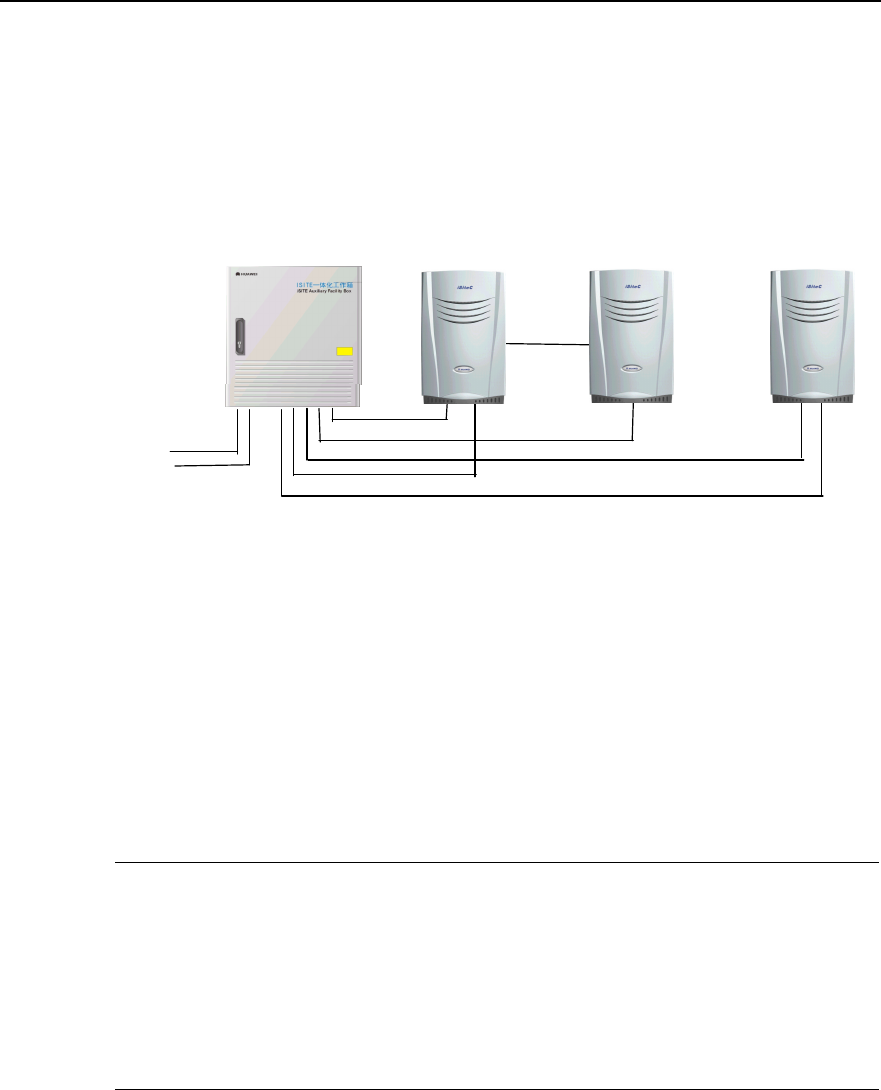
Installation Manual
iSiteC BTS3601C CDMA Base Station Hardware Installation
2 Installing Cabinet Hardware
2-55
2.5.3 Networking of IAFB
I. Plan with backup power supply equipment
Figure 2-53 shows the connection between the IAFB and the BTS3601C in the
BTS3601C networking (without UPS and the IABB).
220VAC
BTS3601C 220VAC Input cable
BTS3601C 220VAC Input cable
ODU3601C 220VAC Input cable
BTS3601C ODU3601C BTS3601C
IAFB
The 1st pair of fiber cables or E1 cable
Cascading
The 2nd pair of fiber cables or E1 cable
Figure 2-53 Networking between BTS3601C and IAFB (without backup power supply equipment)
220V AC power is led into the air switch of the IAFB, then to the BTS3601C. One IAFB
can supply power for up to 3 BTS3601Cs at the same time.
Please connect the relevant cables correctly according to the labels on them, the
correspondence shown in Figure 2-54 and Figure 2-55, and the correspondence
between labels and cables shown in Table 2-3.
&
Note:
1) Figure 2-55 shows the front view of cable connection on DDF shown in Figure 2-54.
2) The PGND cables of BTS3601C and other equipment in the system should all be connected to the
grounding bar on the shell of the IAFB. And a PGND cable should be led from the grounding bar on the
IAFB shell and connected to the grounding downlead of the counterpoise. This grounding cable should be
made of yellow-green plastic insulation copper wire with the core diameter not less than 35mm2.
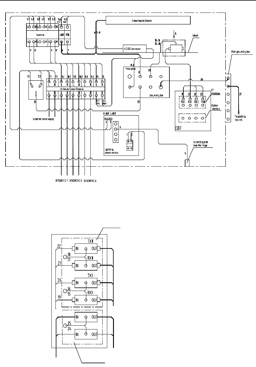
Installation Manual
iSiteC BTS3601C CDMA Base Station Hardware Installation
2 Installing Cabinet Hardware
2-56
Figure 2-54 Cable distribution of IAFB networking (without UPS)
E1 lightning
arrester
To DDF To transmission
device
To HDSL device
HDSL lightning arrester
Input signal cable
Direction A
Figure 2-55 Trunk cable distribution of IAFB networking (without UPS)
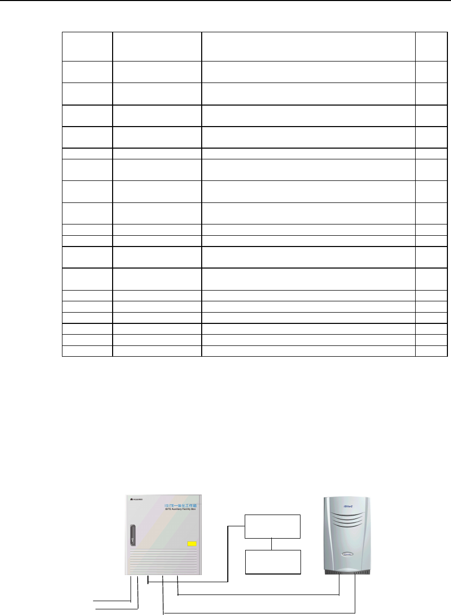
Installation Manual
iSiteC BTS3601C CDMA Base Station Hardware Installation
2 Installing Cabinet Hardware
2-57
Table 2-3 Description of cable distribution in IAFB networking (without UPS)
Cable No. Code Name Quan
tity
1 DKBA04041975WX Power cable connecting air switch to AC lightning protection
box 1
2 DKBA04041976WX Power cable connecting air switch to AC lightning protection
box 1
3 DKBA04041977WX Power cable connecting AC lightning protection box to wiring
terminal 1
4 DKBA04041978WX Power cable connecting AC lightning protection box to wiring
terminal 1
5 DKBA04041979WX Grounding cable for AC lightning protection box 1
6 DKBA04041980WX Power cable connecting transmission equipment to wiring
terminal 1
7 DKBA04041981WX Power cable connecting transmission equipment to wiring
terminal 1
8 DKBA04041982WX Power cable connecting transmission equipment to wiring
terminal 1
9 DKBA04041984WX Power cable from wiring terminal to bipolar air switch 1
10 DKBA04041985WX Power cable from wiring terminal to bipolar air switch 1
11 DKBA04041986WX Power cable connecting wiring terminal to air switch (without
UPS) 1
12 DKBA04041987WX Power cable connecting wiring terminal to air switch (without
UPS) 1
13 DKBA04200197ZP Grounding cable for AC socket 1
15~18 DKBA04200199ZP Grounding cable for signal lightning arrester 4
19~22 DKBA4.851.2527MX E1 interface cable 4
23 DKBA04040980WX PGND cable 1
26 DKBA04041983WX Internal grounding cable for IAFB 1
27 DKBA04040300WX PGND power cable 1
II. Plan with backup power supply equipment
If the mains supply at the BTS3601C side is interrupted, the UPS backup power supply
system will continue to power the BTS3601C and all its auxiliary equipment, instead.
Figure 2-56 shows how the IAFB connects to the BTS3601C and UPS.
220VAC
BTS3601C 220VAC Input cable
BTS3601C
IAFB
The 1st pair of fiber cables or E1 cable
UPS
IABB
Figure 2-56 Networking containing BTS3601C and IAFB (with BTS3601C backup power supply
equipment)
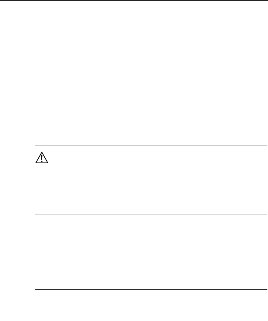
Installation Manual
iSiteC BTS3601C CDMA Base Station Hardware Installation
2 Installing Cabinet Hardware
2-58
Following are their detailed cable connections:
1) Cable connection between UPS and IABB
UPS connects to the IABB via two cables, i.e. one is negative cable and the other is
positive cable. Each cable has one of its ends equipped with a four-core plug to
connect to the UPS. On plugs, labels are attached to tell the positive end (+) and
negative end (-). The other end needs to be prepared at site: There are two big OT
connectors and heat-shrink tubes; cut the available cable (10m long) between the UPS
and the IABB into the piece (with proper length according to the site conditions), then
make the OT connector with a crimping piler and then connect the terminal to the
connector at the battery. This cable should be led through the inlet at the bottom of the
battery box and in. The cable length should be minimized for the sake of lightning
protection.
Caution:
1) The cables must be connected to the UPS and the battery box correctly with their polarities in
correspondence with thoe at the plugs of the UPS and the battery box. Any incorrect connection will result
in the damage of the UPS and batteries.
2) Relabel the cut cable correctly at once if the original label has been damaged when cuting the cable.
2) Cable connection among IAFB, BTS3601C and UPS
It is required to connect cables among IAFB, BTS3601C and UPS according to labels
on them, the correspondence shown in Figure 2-57 and Figure 2-58, and the
correspondence between labels and cables described in Table 2-4.
&
Note:
Figure 2-58 shows the front view of the cable connection on DDF shown in Figure 2-57.
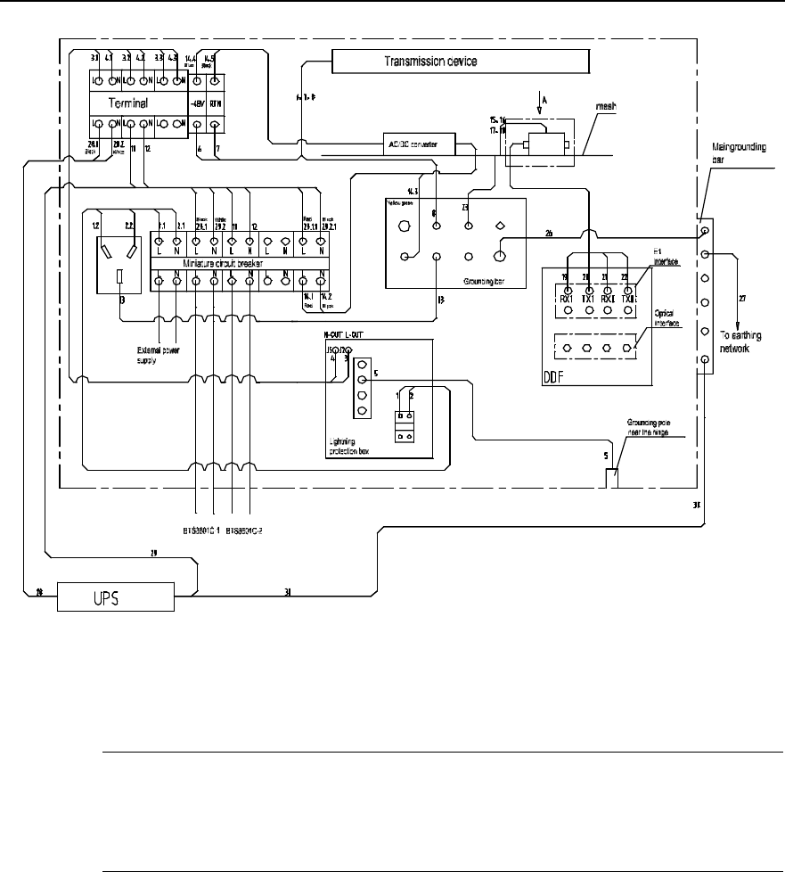
Installation Manual
iSiteC BTS3601C CDMA Base Station Hardware Installation
2 Installing Cabinet Hardware
2-59
Figure 2-57 Cable distribution in IAFB networking
&
Note:
In Figure 2-57, the power of BTS3601C 1 is protected by UPS, i.e. when its power is interrupted, the UPS
will instead supply it with power. However, the BTS3601C 2 is not protected.
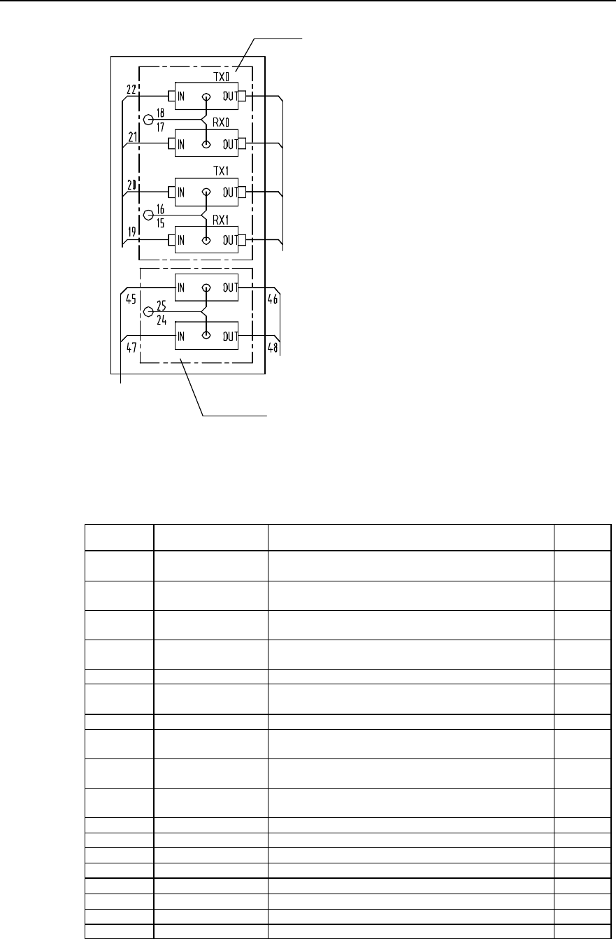
Installation Manual
iSiteC BTS3601C CDMA Base Station Hardware Installation
2 Installing Cabinet Hardware
2-60
E1 lightning arrester
To DDF
A direction
To transmission
device
To HDSL
device
HDSL lightning
arrester
Input signal cable
Figure 2-58 Trunk cable distribution in IAFB networking (1 BTS3601C with UPS)
Table 2-4 Description of cable distribution in IAFB netwroking (1 BTS3601C with UPS)
Cable No. Code Name Quantity
1 DKBA04041975WX Power cable connecting air switch to AC lightning protection
box 1
2 DKBA04041976WX Power cable connecting air switch to AC lightning protection
box 1
3 DKBA04041977WX Power cable connecting AC lightning protection box to
wiring terminal 1
4 DKBA04041978WX Power cable connecting AC lightning protection box to
wiring terminal 1
5 DKBA04041979WX Grounding cable for AC lightning protection box 1
6 DKBA04041980WX Power cable connecting transmission equipment to wiring
terminal 1
7 DKBA04041981WX Power cable from transmission equipment to wiring terminal 1
8 DKBA04041982WX Power cable connecting transmission equipment to wiring
terminal 1
11 DKBA04041986WX Power cable connecting wiring terminal to air switch (without
UPS) 1
12 DKBA04041987WX Power cable connecting wiring terminal to air switch (without
UPS) 1
13 DKBA04200197ZP Grounding cable for AC socket 1
15~18 DKBA04200199ZP Grounding cable for signal lightning arrester 4
19~22 DKBA4.851.2527MX E1 interface cable 4
23 DKBA04040980WX PGND cable 1
26 DKBA04041983WX Internal grounding cable for IAFB 1
27, 30 DKBA04040300WX PGND power cable 2
28 DKBA04041990WX UPS power cable 1
29 DKBA04041991WX UPS POWER CABLE 1
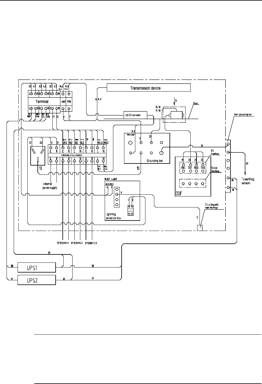
Installation Manual
iSiteC BTS3601C CDMA Base Station Hardware Installation
2 Installing Cabinet Hardware
2-61
An IAFB can connect up to 3 BTS3601Cs. Following is to describe the cable
connections in terms of the varied number of BTS3601C connected to IAFB.
3) IAFB networking (2 BTS3601Cs with UPS)
It is required to connect cables sent to the site according to labels on them, the
connection correspondence shown in Figure 2-59 and Figure 2-60, and the
correspondence between labels and cables described in Table 2-5.
Figure 2-59 Cable distribution in IAFB networking (2 BTS3601Cs with UPS)
&
Note:
In Figure 2-59, if the AC power supply of BTS3601C 1 and BTS3601C 2 is interrupted, UPS will power
them, instead. However, when the AC power of BTS3601C 3 is interrupted, UPS will not power it with AC
power.
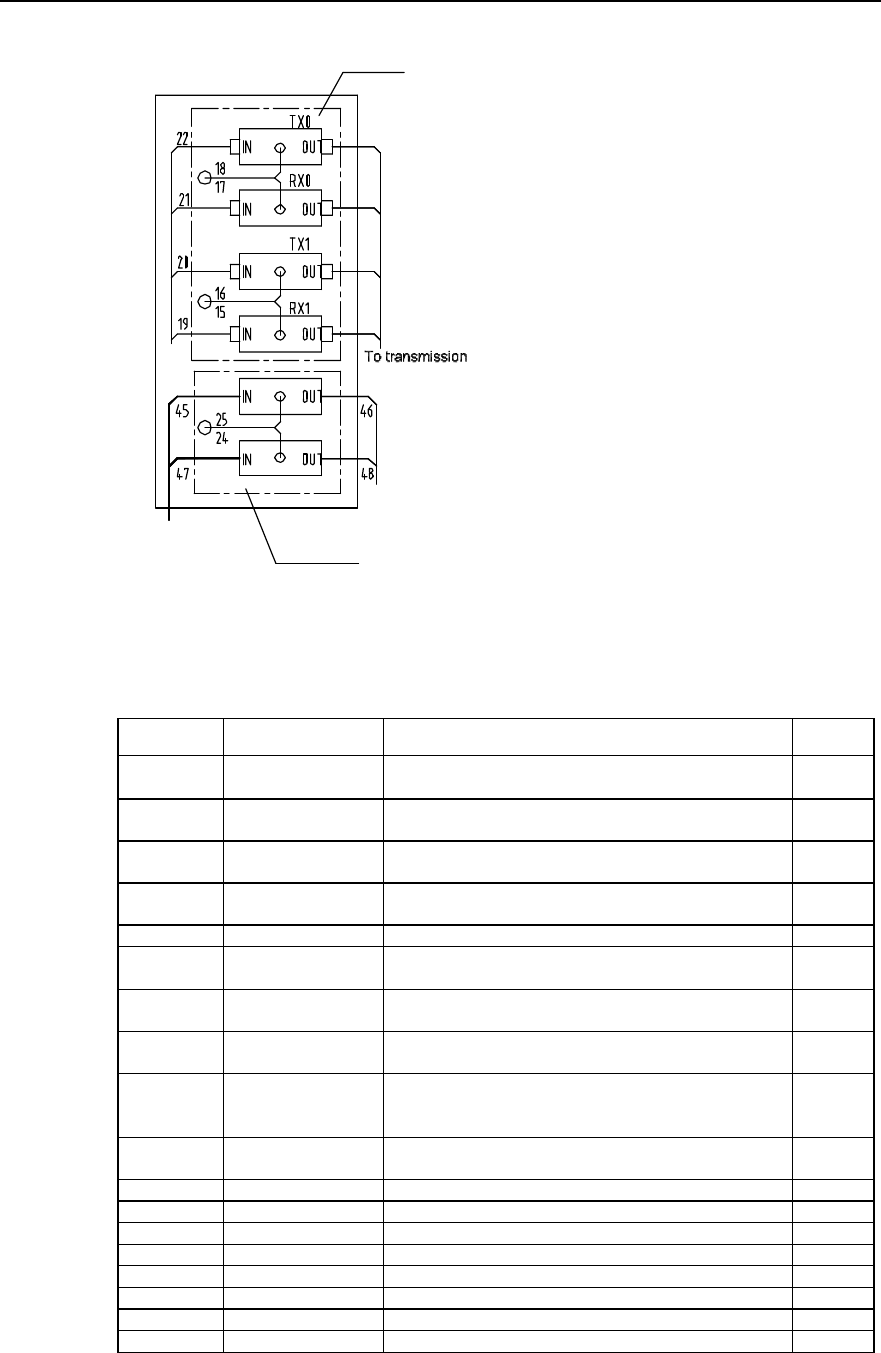
Installation Manual
iSiteC BTS3601C CDMA Base Station Hardware Installation
2 Installing Cabinet Hardware
2-62
E1 lightning
arrester
device
To HDSL device
HDSL lightning
arrester
Input signal cable
To DDF
A direction
Figure 2-60 Trunk cable distribution in IAFB networking (2 BTS3601Cs with UPS)
Table 2-5 Description of cable distribution in IAFB networking (2 BTS3601Cs with UPS)
Cable No. Code Name Quantity
1 DKBA04041975WX Power cable connecting air switch to AC lightning protection
box 1
2 DKBA04041976WX Power cable connecting air switch to AC lightning protection
box 1
3 DKBA04041977WX Power cable connecting AC lightning protection box to
wiring terminal 1
4 DKBA04041978WX Power cable connecting AC lightning protection box to
wiring terminal 1
5 DKBA04041979WX Grounding cable for AC lightning protection box 1
6 DKBA04041980WX Power cable connecting transmission equipment to wiring
terminal 1
7 DKBA04041981WX Power cable connecting transmission equipment to wiring
terminal 1
8 DKBA04041982WX Power cable between transmission equipment and wiring
terminal 1
11 DKBA04041986WX Power cable connecting wiring terminal to air switch (without
UPS)
1
12 DKBA04041987WX Power cable connecting wiring terminal to air switch (without
UPS) 1
13 DKBA04200197ZP Grounding cable for AC socket 1
15~18 DKBA04200199ZP Grounding cable for signal lightning arrester 4
19~22 DKBA4.851.2527MX E1 interface cable 4
23 DKBA04040980WX PGND cable 1
26 DKBA04041983WX Internal grounding cable of IAFB 1
27, 30, 33 DKBA04040300WX PGND power cable 3
28, 31, 32 DKBA04041990WX UPS power cable 3
29 DKBA04041991WX UPS power cable 1
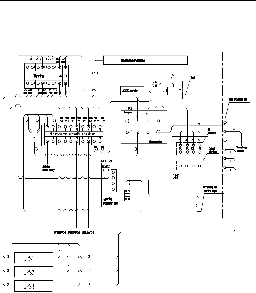
Installation Manual
iSiteC BTS3601C CDMA Base Station Hardware Installation
2 Installing Cabinet Hardware
2-63
4) IAFB networking (3 BTS3601Cs with UPS)
It is required to connect cables sent to the site according to labels on them, the
connection correspondence shown in Figure 2-61 and Figure 2-62, and the
correspondence between labels and cables described in Table 2-6.
Figure 2-61 Cable distribution in IAFB networking (3 BTS3601Cs with UPS)
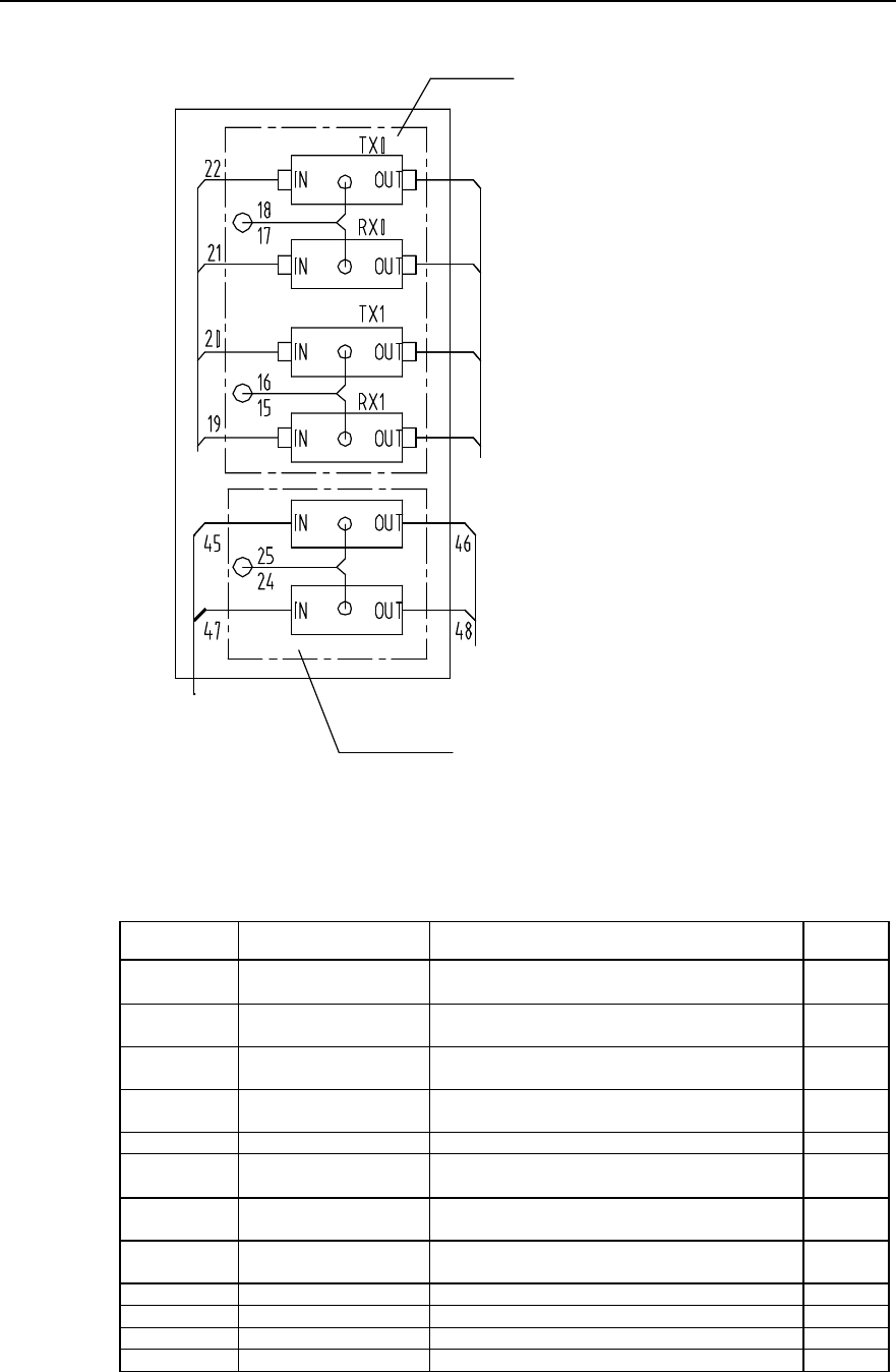
Installation Manual
iSiteC BTS3601C CDMA Base Station Hardware Installation
2 Installing Cabinet Hardware
2-64
A direction
E1 lightning
arrester
To transmission
device
To HDSL device
HDSL lightning arrester
Input signal cable
To DDF
Figure 2-62 Trunk cable distribution in IAFB networking (3 BTS3601Cs with UPS)
Table 2-6 Description of cable distribution in IAFB networking (3 BTS3601Cs with UPS)
Cable No. Code Name Quantity
1 DKBA04041975WX Power cable between air switch and AC lightning
protection box 1
2 DKBA04041976WX Power cable between air switch and AC lightning
protection box 1
3 DKBA04041977WX Power cable between AC lightning protection box and
wiring terminal 1
4 DKBA04041978WX Power cable between AC lightning protection box and
wiring terminal 1
5 DKBA04041979WX Grounding cable for AC lightning protection box 1
6 DKBA04041980WX Power cable connecting transmission equipment to
wiring terminal 1
7 DKBA04041981WX Power cable connecting transmission equipment to
wiring terminal 1
8 DKBA04041982WX Power cables connecting transmission equipment to
wiring terminal 1
13 DKBA04200197ZP Grounding cable for AC socket 1
15~18 DKBA04200199ZP Grounding cable for signal lightning arrester 4
19~22 DKBA4.851.2527MX E1 interface cable 4
23 DKBA04040980WX PGND cable 1
Installation Manual
iSiteC BTS3601C CDMA Base Station Hardware Installation
2 Installing Cabinet Hardware
2-65
Cable No. Code Name Quantity
26 DKBA04041983WX Internal grounding cable of IAFB 1
27, 30, 33, 36 DKBA04040300WX PGND power cable 4
28, 31, 32, 34,
35 DKBA04041990WX UPS power cable 5
29 DKBA04041991WX UPS power cable 1
2.5.4 Networking of Inverter
This networking mode is applied to sites where -48V power supply is available. Figure
2-63 shows the specific networking.
-48V
BTS3601C 220VAC Input cable
BTS3601C
Inverter
A pair of fiber cables or E1 cable
DC lightning
protection box
Grounding cable
Figure 2-63 Inverter networking
It is required that the metal shell of the inverter be grounded, and the PGND cable of
the step-up transformer be connected to BTS3601C grounding busbar directly. The
PGND cable of the inverter should be made of yellow-green plasitc insulation copper
wire with the core diameter not less than 16mm2.
For detailed connections of inverter cables, please refer to the relevant contents in
product manuals.