Huawei Technologies BTS3601C-1900 CDMA Base Station User Manual 4
Huawei Technologies Co.,Ltd CDMA Base Station 4
Contents
- 1. User Manual 1
- 2. User Manual 2
- 3. User Manual 3
- 4. User Manual 4
User Manual 4

Installation Manual
iSiteC BTS3601C CDMA Base Station Software Installation & System Commissioning
Table of Contents
i
Table of Contents
1 Overview of Software Installation ......................................................................................1-1
1.1 Overview of Software Installation ................................................................................1-1
1.1.1 BTS Operational Software ................................................................................1-1
1.1.2 Terminal O&M Software ...................................................................................1-2
2 Installing BTS Terminal O&M Software..............................................................................2-1
2.1 Software Features .....................................................................................................2-1
2.2 Installing Local O&M Software....................................................................................2-1
2.2.1 Operational Environment..................................................................................2-1
2.2.2 Conditions .......................................................................................................2-2
2.2.3 Network Configuration ......................................................................................2-2
2.2.4 Software Installation and Instructions ................................................................2-3
2.3 Installing Remote O&M Software ................................................................................2-3
2.3.1 Operational Environment..................................................................................2-3
2.3.2 Conditions .......................................................................................................2-3
2.3.3 Software Installation and Instructions ................................................................2-3
3 Installing BTS Operational Software..................................................................................3-1
3.1 Software Media .........................................................................................................3-1
3.2 Replacing the Chip ....................................................................................................3-1
3.3 Downloading Software ...............................................................................................3-2
3.3.1 Methods of Software Loading............................................................................3-2
3.3.2 Remote Loading ..............................................................................................3-3
3.3.3 Verifying the Software Version ..........................................................................3-7
4 System Commissioning.....................................................................................................4-1
4.1 Modes of System Commissioning ...............................................................................4-1
4.1.1 Local Commissioning .......................................................................................4-1
4.1.2 Remote Commissioning....................................................................................4-1
4.2 Power-on Operation of Software.................................................................................4-1
4.2.1 Board Startup and Indicator Description.............................................................4-2
4.2.2 Setting up OML ................................................................................................4-2
4.2.3 Setting up Abis Signaling Link...........................................................................4-3
4.2.4 Setting up Cells................................................................................................4-3
4.2.5 Normal Operational Status................................................................................4-3
4.2.6 Clock Reference Source...................................................................................4-3
4.3 Commissioning Board Software..................................................................................4-4
4.3.1 Testing Links ...................................................................................................4-4
4.3.2 Processing Faults and Alarms...........................................................................4-4

Installation Manual
iSiteC BTS3601C CDMA Base Station Software Installation & System Commissioning
Table of Contents
ii
4.3.3 Operation and Maintenance..............................................................................4-5
4.4 Call Function Test......................................................................................................4-9
4.4.1 Test Equipment................................................................................................4-9
4.4.2 Preparations for Service Function Test..............................................................4-9
4.4.3 Service Flow Overview...................................................................................4-10
4.4.4 Test of Location Update Flow..........................................................................4-11
4.4.5 Test of MOC Flow..........................................................................................4-12
4.4.6 Test of MTC Flow...........................................................................................4-12
4.4.7 Test of Handoff Flow......................................................................................4-13
4.4.8 Test of Mobile Originated SMS Flow................................................................4-14
4.4.9 Test of Mobile Terminated SMS Flow..............................................................4-14
4.4.10 Test of Mobile Originated Packet Data Flow...................................................4-15
4.4.11 Test of MS Packet Data Flow (Downlink Service Rate) ...................................4-15
4.4.12 Processing of Abnormalities in the Test .........................................................4-16

Installation Manual
iSiteC BTS3601C CDMA Base Station Software Installation & System Commissioning
Table of Contents
i
Table of Contents
1 Overview of Software Installation ......................................................................................1-1
1.1 Overview of Software Installation ................................................................................1-1
1.1.1 BTS Operational Software ................................................................................1-1
1.1.2 Terminal O&M Software ...................................................................................1-2

Installation Manual
iSiteC BTS3601C CDMA Base Station
Software Installation & System Commissioning
0
错误 表格结果无效
1-1
1 Overview of Software Installation
1.1 Overview of Software Installation
BTS3601C software includes BTS operational software and terminal Operation &
Maintenance (O&M) software.
BTS operational software includes BOOT software, Central Processing Unit (CPU)
software, and Field Programmable Gate Array (FPGA) logic.
CPU software includes Micro-bts Base-band Processing Board (MBPB) software and
Micro-bts Transceiver Board (MTRB) software; while FPGA logic includes MBPB logic
and MTRB logic. The actual situation differs from one board type to another.
Terminal O&M software includes Local Maintenance Function (LMF) software (i.e.,
the local O&M software), and O&M Center (OMC) software (i.e., the remote O&M
software).
LMF software comprises PC self-contained Telnet and File Transfer Protocol (FTP)
software, while OMC software is composed of BAM software and Client software.
1.1.1 BTS Operational Software
I. BOOT software
BOOT software serves to start the board. Before the delivery of the BTS3601C, the
BOOTROM in every board has already been installed with BOOT software. BOOT
software upgrade is usually realized by replacing the chip.
II. CPU software
CPU software is the core of system functions. It can be loaded in two ways:
l If there is no old-version software on the board, it is necessary to load the board
(in the commissioning mode) with the software through the board network port.
l If there is old-version software on the board, the software can be upgraded
through software loading by using local FTP software or remote O&M software.
III. FPGA logic
FPGA logic should be loaded to BTS3601C MBPB/MTRB. The loading mode is the
same as that of CPU software.

Installation Manual
iSiteC BTS3601C CDMA Base Station
Software Installation & System Commissioning
0
错误 表格结果无效
1-2
&
Note:
The BTS operational software has been installed before delivery, so there is no need to install onsite.
However, the operational software needs to be upgraded or re-loaded upon version upgrade. For details,
please refer to Chapter 3 BTS Operation Software Installation.
1.1.2 Terminal O&M Software
I. Local O&M software
The local maintenance console is a portable computer installed with Windows9x
Operating System (OS), which contains the local O&M software. It includes FTP
Client (Ftp.exe) and Telnet Client (Telnet.exe).
The BTS3601C objects, including sites, cells, basebands, carriers, channels, etc.,
can be maintained with local maintenance commands.
Since the two programs (Ftp.exe and Telnet.exe) are provided by Windows9x OS,
there is no need for extra installation.
II. Remote O&M software
Remote O&M software (OMC) of the Base Station Subsystem (BSS) adopts the
Client/Server structure.
Through the Client, users can input operation commands, which are then processed
by the server (BAM) in a centralized way. After the processing, these commands are
transmitted to the foreground (including BSC and BTS), which will then return the
operation result (success, failure, timeout, exception, etc.). BAM will record the result
and transmit it in a certain report format to the Client.
With OMC, the user can perform remote maintenance and monitoring over all the
BTSs that are under his control.
The collected site information can also be used for network planning.
The installation of OMC software involves the installation of BAM server software and
the installation of the Client software.
The Client software is divided into three kinds: BSC Client, BTS3612 Client and
BTS3601C Client.
This manual describes the installation of BTS3601C Client software only. For the
installation of BAM server and other Client software, please refer to the
corresponding installation manual.

Installation Manual
iSiteC BTS3601C CDMA Base Station Software Installation & System Commissioning
Table of Contents
i
Table of Contents
2 Installing BTS Terminal O&M Software..............................................................................2-1
2.1 Software Features .....................................................................................................2-1
2.2 Installing Local O&M Software....................................................................................2-1
2.2.1 Operational Environment..................................................................................2-1
2.2.2 Conditions .......................................................................................................2-2
2.2.3 Network Configuration ......................................................................................2-2
2.2.4 Software Installation and Instructions ................................................................2-3
2.3 Installing Remote O&M Software ................................................................................2-3
2.3.1 Operational Environment..................................................................................2-3
2.3.2 Conditions .......................................................................................................2-3
2.3.3 Software Installation and Instructions ................................................................2-3

Installation Manual
iSiteC BTS3601C CDMA Base Station
Software Installation & System Commissioning
0
错误 表格结果无效
2-1
2 Installing BTS Terminal O&M Software
2.1 Software Features
BTS3601C terminal O&M software (hereinafter referred to as "terminal O&M
software") is classified into two categories: the remote O&M and the local O&M.
These two categories differ in the way they are installed.
I. Local O&M software
Local O&M software includes FTP Client (Ftp.exe) and Telnet Client (Telnet.exe). The
two programs are both self-contained by Windows9x OS.
To realize the local maintenance, the maintenance console is connected through
crossover network cables to BTS via the Ethernet port that is in the Micro-bts
Base-band Processing Module (MBPM) maintenance window. The user thus can
issue O&M commands through the local maintenance console to maintain the
BTS3601C.
II. Remote O&M software
The remote O&M software comprises the software for the BAM server and the Client.
Among which, the Client software is composed of three parts: BSC Client, BTS3612
Client and BTS3601C Client. The remote O&M software described in this manual
refers to BTS3601C Client.
2.2 Installing Local O&M Software
2.2.1 Operational Environment
I. Hardware environment
Basic hardware configuration of the WS (desk-top computer):
l Pentium 100 CPU
l One 500Mbyte hard disk
l One 8Mbyte memory
l One integrated network card

Installation Manual
iSiteC BTS3601C CDMA Base Station
Software Installation & System Commissioning
0
错误 表格结果无效
2-2
II. Software configuration
Windows 95 or Windows 98.
2.2.2 Conditions
For the normal operation of the local maintenance console, the following conditions
should be met:
1) The hardware environment are ready;
2) Windows9x OS can operate normally;
3) Windows9x installation files and network card driver (provided by the original
manufacturer) are furnished.
2.2.3 Network Configuration
This involves the installation and configuration of the network card and the TCP/IP.
The configuration is performed through the functional items of "Add new hardware"
and "Network" in turn on the "Control Panel" of the computer.
The IP address of the maintenance console should be in the same network segment
as that of BTS3601C MBPM network port. In addition, the address should be unique
in the IP addresses of the network equipment.
The connection sequence of network cables (crossover cable) at the network port is
shown in Figure 2-1.
RJ45
Green and white
Green
Yellow and white
Blue
Blue and white
Yellow
Blown and white
Blown
Yellow and white
Yellow
Green and white
Blue
Blue and white
Green
Blown and white
Blown
RJ45
1
2
3
4
5
6
7
8
3
6
1
4
5
2
7
8
RJ45
Green and white
Green
Yellow and white
Blue
Blue and white
Yellow
Blown and white
Blown
Yellow and white
Yellow
Green and white
Blue
Blue and white
Green
Blown and white
Blown
RJ45
1
2
3
4
5
6
7
8
3
6
1
4
5
2
7
8
Figure 2-1 Connection sequence of crossover network cables

Installation Manual
iSiteC BTS3601C CDMA Base Station
Software Installation & System Commissioning
0
错误 表格结果无效
2-3
2.2.4 Software Installation and Instructions
Since Local O&M software (Ftp.exe and Telnet.exe) is self-contained by Windows9x,
there is no need for extra installation.
To run Ftp/Telnet, click [Start/Run] in the system menu of the computer, and input "ftp
xxx.xxx.xxx.xxx"/"telnet xxx.xxx.xxx.xxx" into the dialogue box of [Run].
"xxx.xxx.xxx.xxx" is the IP address of MBPM network port. Ftp/Telnet is then started
for you to log in to the MBPM.
2.3 Installing Remote O&M Software
2.3.1 Operational Environment
The remote O&M software (referring to the BTS3601C Client software here) should
be installed to the same computer together with BSC Client and BTS3612 Client.
2.3.2 Conditions
1) Make sure the computer is installed with only the software necessary for the
system. Otherwise, there may be operational conflicts that may affect the normal
operation of the Client software. Moreover, make sure that a nice and stable
network hardware environment has been established.
2) Obtain from Huawei the complete set of installation files and read-me files, as
well as a legal product serial number.
3) BTS3601C Client software should be installed only after the corresponding BSC
Client and BTS3612 Client have been installed. Before installation, please make
sure that the versions of the three kinds of software are consistent.
2.3.3 Software Installation and Instructions
The BSC Client and BTS3612 Client (both are of the matching versions) should have
been installed first (for instructions, please refer to the corresponding parts in
BSC/BTS3612 installation manuals). After that, to install BTS3601C Client software,
the procedures include:
I. Starting SETUP.EXE
After inserting the installation disk into the disk drive, different alternatives are
provided for:
l If auto execution has been set for the system, the program will be started then.
l Or, you should click [Start/Run] in the system menu and key in "SETUP" and the
corresponding driver icon and path, and press <Enter>.
Installation Manual
iSiteC BTS3601C CDMA Base Station
Software Installation & System Commissioning
0
错误 表格结果无效
2-4
l You can also click [SETUP.EXE] in the Resource Manager to run the program.
l You can copy the files in the installation disk to the hard disk and run them.
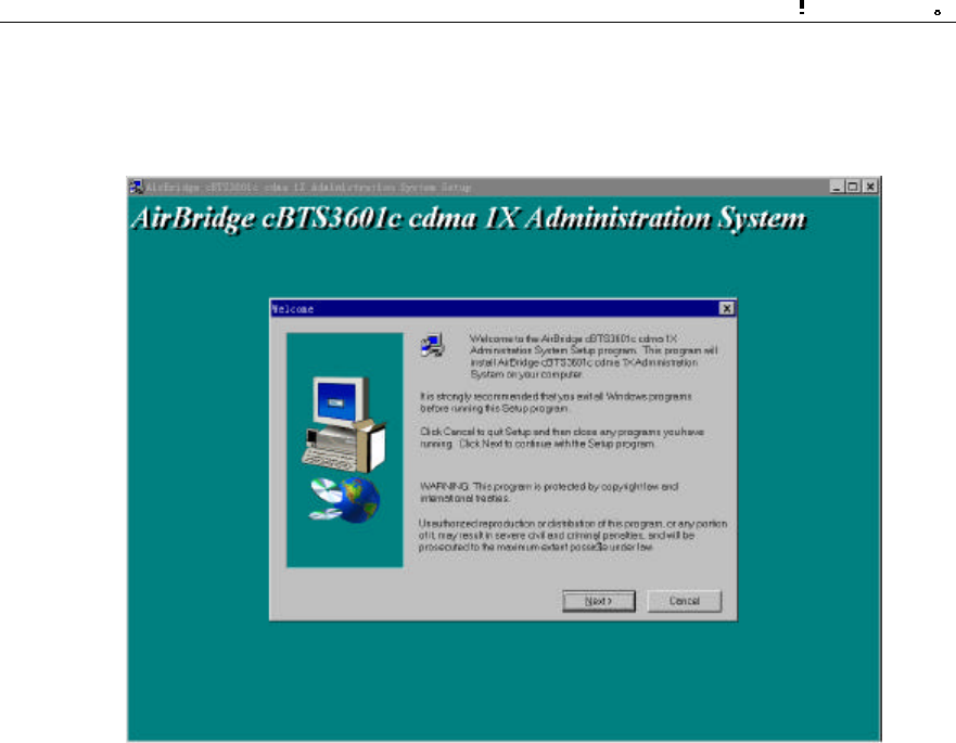
The initial installation interface as shown in Figure 2-2 will then pop up.
Figure 2-2 Initial installation interface
Click <Next> to continue (or click <Cancel> to exit the installation).
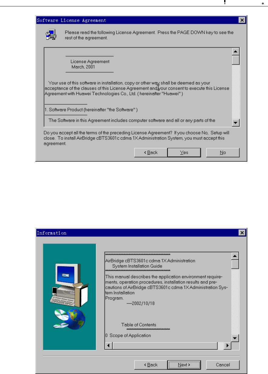
II. License agreement and installation instructions
The [Software License Agreement] will pop up as shown in Figure 2-3. After reading it
carefully, click <Yes> to accept it and continue (or <No> to exit the installation).
Installation Manual
iSiteC BTS3601C CDMA Base Station
Software Installation & System Commissioning
0
错误 表格结果无效
2-5
Figure 2-3 Software license agreement interface
The installation wizard will guide you how to install the software step by step, as
shown in Figure 2-4. It may contain some latest installation information not given in
this manual. Read the information carefully, then click <Next> to continue.
Figure 2-4 Interface of system installation instructions
Installation Manual
iSiteC BTS3601C CDMA Base Station
Software Installation & System Commissioning
0
错误 表格结果无效
2-6
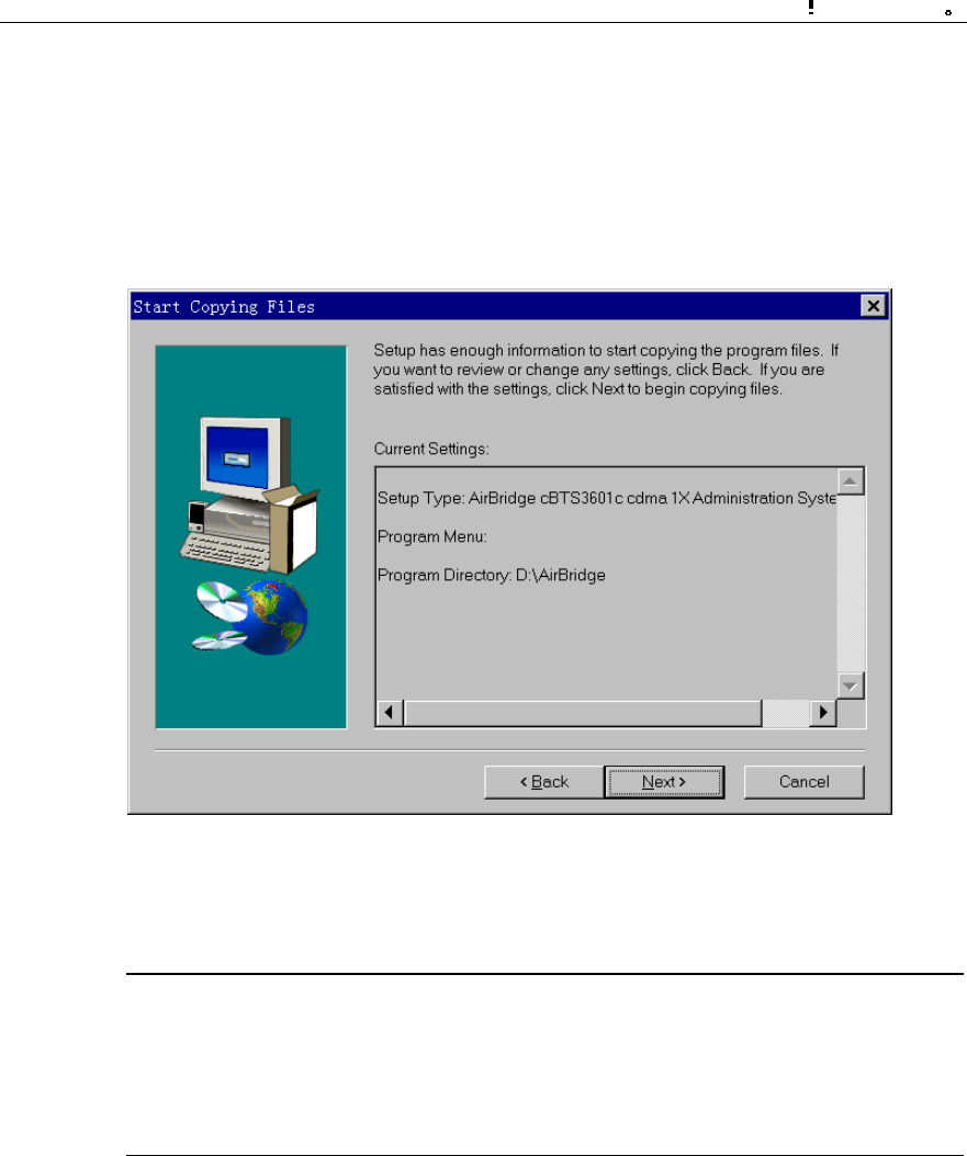
III. Confirming the installation information
You are required to confirm the installation information as shown in Figure 2-5 before
copying files.
If you want to change the installation information, please click <Back> to return to the
previous step. Otherwise, click <Next> to continue.
Figure 2-5 Confirming the installation information
&
Note:
The default installation path for BTS3601C Client software is D:\AirBridge, the same as that of BSC
Client and BTS3612 Client. If the installation path of BSC/BTS3612 Client has been changed, the
installation program of BTS3601C Client will automatically find the new one.
IV. Completing the installation
After confirming the installation information, the installation program will start copying
files. In the process of file copying, the installation program will show such information
including overall progress, available disk space, available memory and progress of
individual file copying.
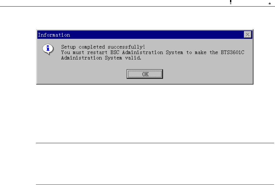
Upon the completion of the installation, the window [Setup Complete] as shown in
Figure 2-6 will pop up.
Installation Manual
iSiteC BTS3601C CDMA Base Station
Software Installation & System Commissioning
0
错误 表格结果无效
2-7
Click <OK>, and the system should be restarted to make the Client software valid.
Figure 2-6 End of the installation
That is the end of the installation of BTS3601C Client software.
&
Note:
The above described installation procedure is the one in normal situation. If abnormality occurs at any
installation procedure, please follow the system prompts.
After the installation, click [Start/Program/Airbridge cBSS cdma 1X Administration
System/ AirBridge cBSS Client] to start the Client software.
The operation interface is shown in Figure 2-7.
Installation Manual
iSiteC BTS3601C CDMA Base Station
Software Installation & System Commissioning
0
错误 表格结果无效
2-8
Figure 2-7 Operation interface of remote O&M software

Installation Manual
iSiteC BTS3601C CDMA Base Station Software Installation & System Commissioning
Table of Contents
i
Table of Contents
3 Installing BTS Operational Software..................................................................................3-1
3.1 Software Media .........................................................................................................3-1
3.2 Replacing the Chip ....................................................................................................3-1
3.3 Downloading Software ...............................................................................................3-2
3.3.1 Methods of Software Loading............................................................................3-2
3.3.2 Remote Loading ..............................................................................................3-3
3.3.3 Verifying the Software Version ..........................................................................3-7

Installation Manual
iSiteC BTS3601C CDMA Base Station
Software Installation & System Commissioning
0
错误 表格结果无效
3-1
3 Installing BTS Operational Software
3.1 Software Media
BTS3601C software has two kinds of media:
l Memory chip
l Disk file
For specific software, their respective media are described as follows:
I. For BOOT software
Boot software includes the fundamental hardware initialization information of boards.
Before delivery, BOOTROMs of all boards are pre-installed with BOOT software,
which can be upgraded by replacing chips.
II. For CPU software
CPU software is the core of system functions. Before delivery, CPU software has
been loaded to the Flash Memory. Once the equipment is powered-on, BOOT
software will load the CPU software from Flash Memory to RAM and run it there.
When CPU software should be reloaded or upgraded during the maintenance
process, CPU software in disk file format can be loaded to the corresponding Flash
Memory through the remote or local maintenance console.
III. For FPGA logic
FPGA logic is responsible for board data exchange. It is loaded in the same way as
the CPU software.
3.2 Replacing the Chip
Generally, the BOOT software is updated by replacing the chip. All you need to do is
to replace the program chip of the old version software with the chip of the new
version.
Installation Manual
iSiteC BTS3601C CDMA Base Station
Software Installation & System Commissioning
0
错误 表格结果无效
3-2
&
Note:
1) The four angles of the chip correspond to those of the socket one by one. Make sure there is no
mistake when replacing the chip. Otherwise, the chip may be burned.
2) The chips should be replaced by authorized Huawei engineers.
3.3 Downloading Software
The boot software of BTS3601C system is installed and upgraded by replacing the
memory chip, while common board software (including CPU software and FPGA logic)
are installed and updated by downloading the software.
3.3.1 Methods of Software Loading
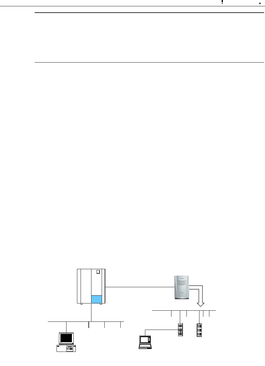
BTS software loading can be conducted through remote/local maintenance console.
The remote maintenance console is connected to BSC via LAN. Through IP Over
ATM (IPOA) link of BSC, it is connected to MBPM of BTS3601C, and through MBPM,
it is connected to Micro-bts Transceiver Module (MTRM).
The local maintenance console is connected to MBPM (via the Ethernet port in
MBPM maintenance window) through the crossover network cable. Through MBPM, it
is then connected to MTRM.
The connection between BTS remote maintenance console and local maintenance
console is shown in Figure 3-1.
BSC BTS3601C
Abis
MBPM MTRM
BAM
(1) (2)
(1) BTS3601C remote maintenance console (2) BTS3601C local maintenance console
Figure 3-1 Connection of BTS3601C maintenance consoles

Installation Manual
iSiteC BTS3601C CDMA Base Station
Software Installation & System Commissioning
0
错误 表格结果无效
3-3
It is quite convenient to load the board software to BTS3601C through remote/local
maintenance console.
The processes of software installation and version upgrade for BTS3601C through
the local and remote maintenance consoles are almost the same.
In the following text, the remote maintenance console is used as an example to
describe the process.
3.3.2 Remote Loading
I. Overview
The system provides the remote loading function to enable the maintenance
personnel to load software to the BTS3601C boards through the remote maintenance
console.
Software loading includes downloading of software and uploading of BTS
configuration data. While the software downloading still comprises two steps:
1) Downloading BTS3601C software;
2) Activating BTS3601C software.
If the loaded software is MBPB software and when it is activated, the BTS3601C will
be reset and MBPB will start the newly-loaded software.
If the loaded software is the MTRB software and when it is activated, MBPB will load
the corresponding MTRB software stored in the memory just now to the specific
board.
In receipt of the new software, the board will activate the software by resetting itself.
The software loading is then completed.
II. Precautions
1) Software loading should be carried out based on the actual conditions.
According to the version matching table, FPGA software should be loaded first,
then the CPU software.
2) Since the solidified software is generally loaded by off-line replacing the chip,
there is no requirement on the sequence.
3) The board software loading should follow the sequence of "MTRB first, MBPB
later". While loading software to a specific board, the sequence of "FPGA first,
CPU later" should be followed.
4) The software version fallback of boards follows the sequence MTRB→MBPB,
the fallback sequence of software on a board is CPU first, then FPGA, so the
general sequence is like this: MTRB.CPUàMTRB.FPGAàMBPB.CPUà
MBPB.FPGA.

Installation Manual
iSiteC BTS3601C CDMA Base Station
Software Installation & System Commissioning
0
错误 表格结果无效
3-4
III. Trouble shooting
Case One: Failed to activate after successful downloading.
Cause analysis: Incorrect parameter for software downloading command, e.g.,
wrong software version No., may result in unsuccessful activation after successful
downloading.
Case two: Failed to download.
Cause analysis: Check the loading sequence first. If that is fine, check the following:
l Is the BAM FTP server powered on?
l Is the access directory open?
l Are the login user name and password correct?
l Does the access directory/file exist?
IV. Specific process of software downloading
1) Preparing for software downloading
Copy the board software to be downloaded to the BTS3601C software loading
directory, which is designated in the BAM. Make sure that the file is writable and
readable.
Meanwhile, note down the software version information.
Finally, log in to the BAM through the remote maintenance console after starting the
FTP server at BAM side.
2) Adding the software loading information in the remote BTS3610C maintenance
system
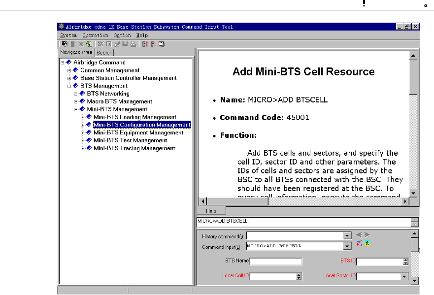
Run the remote maintenance console software (AirBridge cBSS Client), and select
BTS Management in the command tree.
Select Mini-BTS Management\Mini-BTS Loading Management\Add Mini-BTS Loading
Information (MICRO>ADD BTSLDINFO). Click , the shortcut icon of command
Create Input Interface, and input the following:
l [Board Type]: Select the type of the board whose loading information is to be
added.
l [Software Type]: Select the type of board software;
l [Software Version]: Input the version No. (which must meet the related
specification) of the software to be downloaded;
l [File Path]: Input the path for the software to be loaded (i.e. the software loading
directory in the previous step);
l [File Name]: Input the name (the corresponding file name under the software
loading directory in the previous step) of the file to be loaded.

Installation Manual
iSiteC BTS3601C CDMA Base Station
Software Installation & System Commissioning
0
错误 表格结果无效
3-5
Click , the shortcut icon of Execute Command, to add the software loading
information of the corresponding board.
3) Downloading software
Run the remote maintenance console software (AirBridge cBSS Client), and select
BTS Management in the command tree.
Select Mini-BTS Management\Mini-BTS Loading Management\Download BTS
Software or Data Operation (MICRO>DLD BTSSW).
Click , the shortcut icon of command Create Input Interface, and input the
following:
l [BTS Name]: Input the name of the BTS to be downloaded with software (this
entry may be omitted);
l [BTS ID]: Input the ID of the BTS to be downloaded with the software;
l [Software Activation Mode]: Select the activation mode for the software to be
downloaded;
l [Object Type]: Select the type of the object to which the software is to be
downloaded;
l [Software Type]: Select the type of the software to be downloaded;
l [Software Version]: The information that is input here must be consistent with the
version No. of the software whose loading information has been added in the
system;
l [Board ID]: Select the ID of the MTRB to be downloaded with the software.
Click , the shortcut icon Execute Command, to download the software for the
corresponding board.
If the software activation mode is set to be "Automatic Activation", the software will be
activated automatically after the downloading.
V. Activation of BTS3601C software
Run the remote maintenance console software (AirBridge cBSS Client), and select
BTS Management in the command tree.
Select Mini-BTS Management\Mini-BTS Loading Management\Activate Mini-BTS
Software/Configuration (MICRO>ACT BTSSW).
Click , the shortcut icon of command Create Input Interface, and input the
following:

Installation Manual
iSiteC BTS3601C CDMA Base Station
Software Installation & System Commissioning
0
错误 表格结果无效
3-6
[BTS Name]: Input the name of BTS whose software is to be activated (this entry may
be omitted);
[BTS ID]: Input the ID of the BTS whose software is to be activated;
[Object Type]: Select the type of the object whose software is to be activated;
[Software Type]: Select the type of the software to be activated;
[Software Version]: Input the version No. of the software to be activated;
[Board ID]: Select the ID of the corresponding board.
Click , the shortcut icon of Execute Command, to activate the corresponding
board software/data.
&
Note:
The activation of the software can be conducted automatically by the system if the [Software Activation
Mode] is set as "Automatic" during the setup to download the software.
VI. Uploading of BTS3601C configuration data
Run the remote maintenance console software (AirBridge cBSS Client), and select
BTS Management in the command tree.
Select Mini-BTS Management\Mini-BTS Loading Management\Upload BTS Data
Operation (MICRO>ULD BTSCFG).
Click , the shortcut icon of command Create Input Interface, and input the
following:
[BTS Name]: Input the name of BTS whose configuration data is to be uploaded (this
entry may be omitted);
[BTS ID]: Input the ID of the BTS whose data is to be uploaded;
[Object Type]: Select the type of the object whose data is to be uploaded.
Click , the shortcut icon of command Execute Command, to upload the
corresponding BTS3601C configuration data.

Installation Manual
iSiteC BTS3601C CDMA Base Station
Software Installation & System Commissioning
0
错误 表格结果无效
3-7
If this operation is successful, BTS3601C will operate by FTP to upload the
configuration information of the specified version to the remote BAM, and save it
under the file loading path designated when adding the software loading information.
3.3.3 Verifying the Software Version
You can execute a query command through the remote/local maintenance console to
get the version information of the running software on BTS3601C boards.
I. Get the version information of board software through the remote
maintenance console
Run the remote maintenance console software (AirBridge cBSS Client), and select
BTS Management in the command tree.
Select Mini-BTS Management\Mini-BTS Equipment Management\Query Mini-BTS
Board Version Information (MICRO>DSP BTSBRDVER).
Click , the shortcut icon of command Create Input Interface, and input the
following:
[BTS Name]: Input the name of the BTS which is to be downloaded with software
(this entry may be omitted);
[BTS ID]: Select the ID of the BTS to be queried;
[Board Type]: Select the type of the BTS board to be queried;
[Board ID]: Select the ID of the BTS MTRB to be queried (if [Board Type] is selected
to be Micro-bts Base-band Processing Board (MBPB), this parameter will not appear).
Click , the shortcut icon of Execute Command, to get the query result of BTS
board version information in the maintenance window.
II. Query the board version information through the local maintenance
console
Start Telnet at the local maintenance console. Input the following command under the
prompt character after the login:
DSP BTSBRDVER:BRDTP=<MBPB>,BRDID=<0>
BRDTP is the type of the board to be queried, and BRDID is the ID of the board to be
queried.

Installation Manual
iSiteC BTS3601C CDMA Base Station
Software Installation & System Commissioning
0
错误 表格结果无效
3-8
&
Note:
1) When BRDTP is selected as MTRB, the parameter BRDID (value range: 0-5) must be specified.
2) When BTDTP is selected as MBPB, the parameter BRDID (value: 0) is optional.

Installation Manual
iSiteC BTS3601C CDMA Base Station Software Installation & System Commissioning
Table of Contents
i
Table of Contents
4 System Commissioning.....................................................................................................4-1
4.1 Modes of System Commissioning ...............................................................................4-1
4.1.1 Local Commissioning .......................................................................................4-1
4.1.2 Remote Commissioning....................................................................................4-1
4.2 Power-on Operation of Software.................................................................................4-1
4.2.1 Board Startup and Indicator Description.............................................................4-2
4.2.2 Setting up OML ................................................................................................4-2
4.2.3 Setting up Abis Signaling Link...........................................................................4-3
4.2.4 Setting up Cells................................................................................................4-3
4.2.5 Normal Operational Status................................................................................4-3
4.2.6 Clock Reference Source...................................................................................4-3
4.3 Commissioning Board Software..................................................................................4-4
4.3.1 Testing Links ...................................................................................................4-4
4.3.2 Processing Faults and Alarms...........................................................................4-4
4.3.3 Operation and Maintenance..............................................................................4-5
4.4 Call Function Test......................................................................................................4-9
4.4.1 Test Equipment................................................................................................4-9
4.4.2 Preparations for Service Function Test..............................................................4-9
4.4.3 Service Flow Overview...................................................................................4-10
4.4.4 Test of Location Update Flow..........................................................................4-11
4.4.5 Test of MOC Flow..........................................................................................4-12
4.4.6 Test of MTC Flow...........................................................................................4-12
4.4.7 Test of Handoff Flow......................................................................................4-13
4.4.8 Test of Mobile Originated SMS Flow................................................................4-14
4.4.9 Test of Mobile Terminated SMS Flow..............................................................4-14
4.4.10 Test of Mobile Originated Packet Data Flow...................................................4-15
4.4.11 Test of MS Packet Data Flow (Downlink Service Rate) ...................................4-15
4.4.12 Processing of Abnormalities in the Test .........................................................4-16

Installation Manual
iSiteC BTS3601C CDMA Base Station
Software Installation & System Commissioning
0
错误 表格结果无效
4-1
4 System Commissioning
4.1 Modes of System Commissioning
4.1.1 Local Commissioning
Local commissioning is performed through BTS3601C local maintenance console.
The user can log in to the BTS3601C in the Telnet mode, and commission the
BTS3601C objects with Man-Machine-Language (MML) commands.
Please refer to the module of "Maintenance Console" in User Manual for details of
commissioning commands.
4.1.2 Remote Commissioning
In the remote commissioning mode, the user can input the commissioning command
at the OMC Client. After receiving the command, BAM server will process it and send
it to the BTS3601C. When the response returns from the BTS3601C, BAM server will
record the operation result (success, failure, timeout, abnormality, etc.) and send the
returned operation result in a certain report format to the Client.
For specific operations, please refer to cBSC Operation Manual.
4.2 Power-on Operation of Software
After the BTS3601C is powered on, the software of various boards will conduct
self-test and necessary initialization.
After the system operation becomes stable, MBPB will acquire the basic configuration
parameters to set up the Operation & Maintenance Link (OML) for the BTS3601C
(The protocol involved is BOOTP, a standard protocol in TCP/IP protocol family, which
can be used to obtain IP automatically).
MBPB will also judge whether there are correct configuration data in the BTS3601C
Flash Memory. If there are correct configuration data, MBPB will directly send the
data to each board for configuration. If there is no correct data, MBPB will request the
data from OMC, and send it to the BTS3601C boards for configuration.
The following section briefs the startup and operation of BTS3601C.

Installation Manual
iSiteC BTS3601C CDMA Base Station
Software Installation & System Commissioning
0
错误 表格结果无效
4-2
4.2.1 Board Startup and Indicator Description
When the BTS3601C is powered-on, BOOT software of each board will start running
to transfer CPU software from Flash Memory to Random-Access Memory (RAM), and
start the self-test and initialization.
If the initialization is successful, the board will send a request to Operation &
Maintenance Unit (OMU) for configuration; otherwise, board will be reset and
restarted.
There are three indicators on both the board panels in the maintenance window of
MBPM and MTRM respectively. From top to bottom they are: RUN (operation
indicator, green), ALM (alarm indicator, red) and ACT (work indicator, green).
The following briefs the statuses of indicators. For details, please refer to chapter
"Introduction to Module Maintenance Window" in the User Manual.
l When MBPB/MTRB has no configuration data, all the three indicators will fast
flash at the frequency of 4Hz.
l When MBPB/MTRB is downloading the software, indicator RUN will fast flash at
the frequency of 4Hz.
l When the board is in normal operation, indicator RUN flashes slowly at the
frequency of 0.5Hz, while "ACT" keeps on, and "ALM" is off.
l When alarms occur in the operation of the board, indicator ALM will flash at
different frequencies to indicate different alarm levels.
4.2.2 Setting up OML
After the self-test, MBPB will set up OML with OMC first.
OML is set up through the following procedures:
1) MBPB in the BTS3601C sends BOOTP request to OMC;
2) After receiving BOOTP request from the BTS3601C, OMC will fill the
corresponding BOOTP response frame (including the IP address, subnet mask,
gateway address, etc. of this BTS3601C) according to BOOTP information of the
relevant BTS3601C configured before. OMC will then send the frame to the
BTS3601C.
3) According to the received BOOTP response frame, BTS3601C will set its own IP
address and the related routing data;
4) After obtaining IP address and creating the route, the BTS3601C will send to
OMC a request to setup TCP link. In receipt of the request, OMC will set up the
OML to that BTS3601C.

Installation Manual
iSiteC BTS3601C CDMA Base Station
Software Installation & System Commissioning
0
错误 表格结果无效
4-3
4.2.3 Setting up Abis Signaling Link
After the configuration of the BTS3601C, MBPB will set up Abis signaling link
according to the configured parameters and exchange signaling with the BSC.
4.2.4 Setting up Cells
When Abis signaling link is set up, MBPB will report the configuration status of
BTS3601C resources to BSC and ask for logical configuration.
After BSC sends cell configuration data to MBPB, BTS3601C will configure the
relevant carrier attributes, set up common channel and update the overall messages.
So far the cell has been set up and MSs can access the network and originate calls.
4.2.5 Normal Operational Status
Once the BTS3601C comes into normal operation, MSs can access the network and
make calls.
However, sometimes it is found that although MTRM is in normal operation without
any critical alarms, MSs cannot access the network and make calls. To solve such
problem, the user can take the following measures:
l Check whether MTRM has power output.
l Check whether the system messages are issued normally.
l Trace and locate the fault by using a signaling analyzer or the Abis interface
tracing function of the maintenance console.
During the operation, if the board ALM indicator flashes, it indicates that alarms have
been generated. In this case, the user can query at the BTS3601C terminal
maintenance console for specific alarm description and take the corresponding
measures.
4.2.6 Clock Reference Source
The cdma2000 1X is a synchronization system. A precise reference clock should be
provided for the BTS3601C.
The BTS3601C can receive the clock signal from multiple clock reference sources,
including: GPS clock reference source, GLONASS clock reference source and
external clock reference source.

Installation Manual
iSiteC BTS3601C CDMA Base Station
Software Installation & System Commissioning
0
错误 表格结果无效
4-4
4.3 Commissioning Board Software
4.3.1 Testing Links
The normal operation of communication links is the precondition for the board
software to operate normally. By querying alarms, the user can check whether the
OMLs between BTS3601C boards and OMU are normal, and whether the signaling
links between the boards and the main control Signaling Processing Unit (SPU) are
normal.
Besides, users can use the BTS3601C local/remote maintenance console to issue
commands to perform loopback test on the boards. In this way, the user can ensure
the normal operation of the communication links.
4.3.2 Processing Faults and Alarms
I. Description of alarms
The faults occurred on the modules during BTS3601C operation will be reported to
OMU in logs or alarms. After recording and processing, OMU will report them to
OMC.
The alarms generated by BTS3601C include the following levels: critical, major, minor
and notice.
What follows is the introduction to various module alarms items:
l Common alarm
This alarm item includes the following alarms: 1. Board parameter configuration error
alarm; 2. Board temperature abnormal alarm; 3. Board communication link fault alarm;
4. Optical interface no signal alarm. 5. CUP overload alarm.
l MBPB alarm
This alarm item includes the following alarms: 1. OML interrupted alarm; 2. Abis
signaling link fault alarm; 3. Satellite antenna feeder system fault alarm; 4. System
clock abnormal alarm; 5. Master clock out of lock alarm; 6, UNI link alarm; 7. E1/T1
link local alarm; 8. E1/T1 link remote alarm; 9. ASU fault alarm.
l MTRB alarm
This alarm item includes the following alarms: 1. Receive channel over-activated
alarm; 2. Transmit channel clock unlocked alarm; 3. Hardware phase-lock loop
unlocked alarm; 4. Software phase-lock loop unlocked alarm; 5. I0 value abnormal
alarm; 6. Digital down-converter alarm. Besides, the related alarms including fan,
power amplifier and MLNA alarms are also reported through MTRM.

Installation Manual
iSiteC BTS3601C CDMA Base Station
Software Installation & System Commissioning
0
错误 表格结果无效
4-5
II. Alarm processing
Boards will report a message to OMU when an alarm is generated or cleared.
Accordingly, OMU will set the board availability status and take related measures.
OMU will report all the alarms to OMC to facilitate operators locate the fault before
further measures can be taken.
4.3.3 Operation and Maintenance
BTS3601C provides convenient O&M function to manage and maintain the
BTS3601C equipment. The functions include loading management, configuration
management, equipment management, tracing management and testing
management.
What follows is the description of some daily maintenance operations from the angle
of OMC terminal.
I. Equipment management
1) Querying the operation status of BTS3601C boards
Run the remote maintenance console software (AirBridge cBSS Client), and select
BTS Management in the command tree.
Select Mini-BTS Management\Mini-BTS Equipment Management\Query Mini-BTS
Board Status (MICRO>DSP BTSBRDSTAT).
Click , the shortcut icon of command Create Input Interface, and input the
following:
l [BTS Name]: Input the name of the BTS (this entry may be omitted);
l [BTS ID]: Select the ID of the BTS to be queried;
l [Board Type]: Select the type of the BTS board to be queried;
l [Board ID]: Select the ID of the BTS MTRB to be queried (when [Board Type] is
selected to be MBPB, this parameter will not appear).
Click , the shortcut icon of Execute command, to display the query result about
the corresponding BTS board status in the maintenance window.
2) Querying the version information of BTS3601C boards
Run the remote maintenance console software (AirBridge cBSS Client), and select
BTS Management in the command tree.
Select Mini-BTS Management\Mini-BTS Equipment Management\Query Mini-BTS
Board Version Information (MICRO>DSP BTSBRDVER).

Installation Manual
iSiteC BTS3601C CDMA Base Station
Software Installation & System Commissioning
0
错误 表格结果无效
4-6
Click , the shortcut icon of Create Input Interface, and input the following:
l [BTS Name]: Input the name of the BTS (this entry may be omitted);
l [BTS ID]: Select the ID of the BTS to be queried;
l [Board Type]: Select the type of the BTS board to be queried;
l [Board ID]: Select the ID of the BTS MTRB to be queried (when [Board Type] is
selected to be MBPB, this parameter will not appear).
Click , the shortcut icon of Execute command , to display the query result of
BTS board version information in the maintenance window.
3) Resetting BTS3601C boards
Boards can be reset through the BTS3601C remote/local O&M console. OMU issues
the board resetting command to the corresponding board. In receipt of the command,
the board will reset itself, send the reset report message to and wait for the
initialization data from OMU.
Board reset will affect the system operation status. It is recommended that the user
use it prudently.
The method to reset BTS3601C boards on the remote BTS3601C maintenance
console is as follows:
Run the remote maintenance console software (AirBridge cBSS Client), and select
BTS Management in the command tree.
Select Mini-BTS Management\Mini-BTS Equipment Management\Reset Mini-BTS
Board (MICRO>RST BTSBRD).
Click , the shortcut icon of command Create Input Interface, and input the
following:
l [BTS Name]: Input the name of the BTS (this entry may be omitted);
l [BTS ID]: Select the ID of the BTS to be managed.
l [Board Type]: Select the type of the BTS board to be reset.
l [Board ID]: Select the ID of the BTS MTRB to be reset (when [Board Type] is
selected to be MBPB, this parameter will not appear);
l [Level of resetting]: Select the level of the reset.
Click , the shortcut icon of Execute command, to reset the corresponding BTS
board.
II. Tracing management
1) Starting BTS3601C resource tracing

Installation Manual
iSiteC BTS3601C CDMA Base Station
Software Installation & System Commissioning
0
错误 表格结果无效
4-7
Run the remote maintenance console software (AirBridge cBSS Client), and select
BTS Management in the command tree.
Select Mini-BTS Management\Mini-BTS Tracing Management\Start Mini-BTS
Resource Tracing (MICRO>STR BTSRESTRC).
Click , the shortcut icon of command Create Input Interface, and input the
following:
l [BTS Name]: Input the name of the BTS (this entry may be omitted);
l [BTS ID]: Select the ID of the BTS to be managed;
l [Board Type]: Select the type of the board to be traced;
l [Board ID]: Select the ID of the BTS MTRB to be traced (when [Board Type] is
selected to be MBPB, this parameter will not appear);
l [Resource Type]: Select the type of the resource to be traced.
Click , the shortcut icon of Execute command, to display the tracing result of
the corresponding BTS3601C board resource in the maintenance window.
2) Stopping BTS3601C resource tracing
Run the remote maintenance console software (AirBridge cBSS Client), and select
BTS Management in the command tree.
Select Mini-BTS Management\Mini-BTS Tracing Management\Stop Mini-BTS
Resource Tracing (MICRO>STP BTSRESTRC).
Click , the shortcut icon of Create Input Interface, and input the following:
l [BTS Name]: Input the name of the BTS (this entry may be omitted);
l [BTS ID]: Select the ID of the BTS to be managed;
l [Board Type]: Select the type of the board no longer to be traced.
l [Board ID]: Select the ID of the BTS MTRB no longer to be traced (when [Board
Type] is selected to be MBPB, this parameter will not appear);
l [Resource Type]: Select the type of the resource no longer to be traced.
Click , the shortcut icon of Execute command, to stop tracing the corresponding
BTS3601C board resource.
III. Test management
1) Starting BTS3601C loopback test
The loopback test can be conducted on the BTS3601C remote maintenance console
to check the status of the BTS3601C MBPB-MTRB OML. The following describes the
method to perform the loopback test.

Installation Manual
iSiteC BTS3601C CDMA Base Station
Software Installation & System Commissioning
0
错误 表格结果无效
4-8
Run the remote maintenance console software (AirBridge cBSS Client), and select
BTS Management in the command tree.
Select Mini-BTS Management\Mini-BTS Test Management\Start Mini-BTS Loopback
Test (MICRO>STR BTSLPBACKTST).
Click , the shortcut icon of Create Input Interface, and input the following:
l [BTS Name]: Input the name of the BTS (this entry may be omitted);
l [BTS ID]: Select the ID of the BTS to be managed;
l [Board ID]: Select the number of the MTRB to be tested.
l [Test Type]: Select the type of the loopback to be conducted.
l [Time of Loopback]: Select or input the number of times that the loopback test
will be conducted.
Click , the shortcut icon of command Execute command, to start the loopback
test for the corresponding BTS3601C board.
2) Stopping BTS3601C loopback test
Run the remote maintenance console software (AirBridge cBSS Client), and select
BTS Management in the command tree.
Select Mini-BTS Management\Mini-BTS Test Management\Stop Mini-BTS Loopback
Test (MICRO>STP BTSLPBACKTST).
Click , the shortcut icon of command Create Input Interface, and input the
following:
l [BTS Name]: Input the name of the BTS (this entry may be omitted);
l [BTS ID]: Select the ID of the BTS to be managed;
l [Board ID]: Select the number of the MTRB on which the loopback test is to be
stopped.
l [Test Type]: Select the type of the loopback to be stopped.
Click , the shortcut icon of Execute command, to stop the loopback test on the
corresponding BTS3601C board.
3) Starting BTS3601C E1 test
BTS3601C E1 test can be conducted on the remote O&M console to check the
BSC-BTS physical transmission link, so as to locate the transmission fault or evaluate
the quality of the transmission link.
Run the remote maintenance console software (AirBridge cBSS Client), and select
BTS Management in the command tree.

Installation Manual
iSiteC BTS3601C CDMA Base Station
Software Installation & System Commissioning
0
错误 表格结果无效
4-9
Select Mini-BTS Management\Mini-BTS Test Management\Start Mini-BTS E1 Test
(MICRO>STR BTSE1TST).
Click , the shortcut icon of Create Input Interface, and input the following:
l [BTS Name]: Input the name of the BTS (this entry may be omitted);
l [BTS ID]: Select the ID of the BTS to be managed;
l [Test Type]: Select the type of the loopback to be conducted;
l [Duration of Test (min)]: Select or input the time that the loopback test will last.
This is an optional parameter. By default: 5min.
Click , the shortcut icon of Execute command , to start the loopback test on the
corresponding BTS3601C E1 link.
4.4 Call Function Test
After the hardware installation, check, software installation and basic commissioning,
the user should start the BTS3601C overall function test: service function test.
4.4.1 Test Equipment
I. Abis interface signaling monitoring
Connect the signaling protocol tester (such as K1205 and MA10) to the E1 cables
between BSC and BTS. Set the protocol stack as Abis interface, and select the
timeslot to be monitored according to BSC configuration.
If no signaling tester is available, the OMC interface tracing function also works.
II. Call generator
It is used to simulate multi-user call setup.
III. Test MS
It is used to test the service functions.
4.4.2 Preparations for Service Function Test
Before the test, make the following preparations:
1) Make sure that BSC and BTS3601C are properly connected. BSC and
BTS3601C can be connected via E1/T1 or optical fiber. Make sure that the
connection is correct before the system is powered on.

Installation Manual
iSiteC BTS3601C CDMA Base Station
Software Installation & System Commissioning
0
错误 表格结果无效
4-10
2) Make sure the O&M and signaling links on Abis interface are connected properly.
The connection status of the OMLs and signaling links on Abis interface can be
queried through the OMC BAM.
3) Make sure cell configuration is correct, and the MS can access the network at
the configured frequency.
4.4.3 Service Flow Overview
When switched on, an MS may be either in the idle mode or the dedicated mode. In
the idle mode, the MS will monitor the radio surroundings and find a suitable service
cell to stay; then the MS will monitor the paging channel in the service cell so as to
receive the paging messages from the network side. In the dedicated mode, the MS
exchanges signaling and data with the network.
The basic flow is as follows:
1) Location update flow
2) Mobile Originated Call (MOC) flow
3) Mobile Terminated Call (MTC) flow
4) Handoff flow
5) Mobile originated SMS flow
6) Mobile terminated SMS flow
7) Mobile originated call packet data flow
8) MS packet data flow (downlink service rate)
Flows 1), 2), 3), and 4) are of basic radio connection; while flows 5), 6), 7), and 8) can
be independent flows, or be additional part of flows 1), 2), 3), and 4).
I. Location update flow
The MS notifies the network of its current location in the network through the location
update flow so that the network can provide service.
In the following situations, MSs will originate the location update:
l When an MS moves into a new location area
l When it is time to perform periodic location registration. The time for periodic
location update is designated in the system message received from the network.
II. Mobile originated/terminated call setup flow
These are two basic connection flows of CDMA system. The call may be a speech
call, or a data call.
In an mobile originated call, the called party may be a CDMA mobile subscriber, a
PSTN subscriber, an ISDN subscriber, a CSPDN subscriber or a PSPDN subscriber.

Installation Manual
iSiteC BTS3601C CDMA Base Station
Software Installation & System Commissioning
0
错误 表格结果无效
4-11
In the mobile terminated calls, the calling party may be a cdma2000 1X mobile
subscriber, a PSTN subscriber, an ISDN subscriber, a CSPDN subscriber or a
PSPDN subscriber.
III. Handoff flow
In cdma2000 1X system, handoff has three types: soft handoff, softer handoff and
hard handoff.
Soft handoff or softer handoff can ensure MSs the uninterrupted service when they
are crossing the cell or sector border; while in the hard handoff, the existing
connection has to be cut off before the new connection can be set up.
If the subscriber's current channel suffers from serious interference, the service on it
can be handed over to another channel to prevent the interruption. The QoS is thus
improved. The handoff flow is an important means for the operators to deal with
temporary service overload of cells.
The handoff flow is not independent. It is a part of other basic service flows.
IV. Mobile originated/terminated Short Message Service (SMS) flow
cdma2000 1X supports the point-to-point SMS flow, so that subscribers can send and
receive SMs. It is different from the cell broadcast SMS, which is the
point-to-multipoint broadcast service.
Mobile originated SMS flow is to send an short message from the MS to the Message
Center (MC); on the contrary, mobile terminated SMS flow is to send an short
message from the MC to the MS.
V. MS packet data flow
cdma2000 1X supports packet data service flow. It provides the high-speed data
service transmission capability of up to 156.3kbit/s.
The MS can be used either as a terminal to run data services such as surfing the
internet and sending/receiving E-mails, or as a data channel for other terminals (such
as computer and PDA) to run data services.
4.4.4 Test of Location Update Flow
I. Test condition
The test MS has been defined in HLR.

Installation Manual
iSiteC BTS3601C CDMA Base Station
Software Installation & System Commissioning
0
错误 表格结果无效
4-12
II. Test steps
1) Make sure the network data setting is correct.
2) Switch on the test MS
3) Observe the signaling on Abis interface.
III. Expected test result
By tracing the signaling on Abis interface, the possible results of the location update
include:
1) The network side accepts the MS location update request;
2) The network side rejects the MS location update request.
4.4.5 Test of MOC Flow
I. Test condition
This test should be conducted after a successful location update flow, when the MS
should display the current PLMN No. or operator name.
II. Test steps
Call a PSTN subscriber with the MS.
III. Expected test result
In normal cases, the called PSTN subscriber establishes a bidirectional conversation
with the MS after ringing and off-hook.
4.4.6 Test of MTC Flow
I. Test condition
This test must be preceded by a successful location update flow. The called MS
should reside in the coverage of the tested BTS3601C, and display the current PLMN
No. or operator name of the network.
II. Test steps
Call the test MS from a PSTN telephone set.
III. Expected test result
In normal cases, the test MS establishes a conversation with the calling PSTN
subscriber after ringing and off-hook.

Installation Manual
iSiteC BTS3601C CDMA Base Station
Software Installation & System Commissioning
0
错误 表格结果无效
4-13
4.4.7 Test of Handoff Flow
I. Test condition
1) This test should be performed after the above three tests and in the area
covered by at least two cells. One of cell should be configured with several
sectors, so that the test of the softer handoff can be conducted.
2) The sectors (or omni cells) that compose the overlapped radio coverage should
be configured with different frequencies, so that the hard handoff can be
conducted.
3) The related handoff data should have been configured;
4) Dedicated test MSs;
5) Change the IMSI of the MS, and redefine the subscriber. In this way, the MS can
access the network by selecting a certain basic frequency or auxiliary frequency
in the sector (or omni cell) that is configured with multiple frequencies.
II. Test steps
1) Use an MS to call a PSTN subscriber and establish a conversation.
2) Move the MS from the source sector to the adjacent sector within the same cell
to test the softer handoff performance.
Only when the adjacent sector is also configured with the frequency at which the
MS has established the conversation in the source sector, and the frequency is
available, can the softer handoff be achieved.
3) Move the MS from the source cell to the target cell to test the soft/hard handoff
performance.
When the MS establishes a connection at a frequency in the source cell, while the
target cell is not configured with this frequency, the hard handoff will occur. If the
target cell is configured with this frequency and this frequency is available, the soft
handoff will occur.
III. Expected test result
1) Soft handoff and softer handoff
Normally, when the MS moves to the adjacent cell/sector, the target pilot channel will
be shown in the active set of the MS pilot set.
During the conversation, the mobile subscriber feels no interruption or call drop, and
the voice quality is good.
2) Hard handoff
Normally, when the MS moves to the adjacent cell or sector, it is visible in the active
set of the MS pilot set that the source pilot channel is deleted, and the target pilot
channel is added.

Installation Manual
iSiteC BTS3601C CDMA Base Station
Software Installation & System Commissioning
0
错误 表格结果无效
4-14
The mobile subscriber will feel temporary conversation interruptions.
&
Note:
If the actual test conditions cannot meet the standard, the test flow can be simplified like this: Make an
MOC/MTC, and move the MS repeatedly between the adjacent cells, or between the adjacent sectors in
one cell. Whether the handoff flow is normal or not can be judged by observing whether or not there are
conversation interruptions, and by the voice quality.
4.4.8 Test of Mobile Originated SMS Flow
I. Test condition
1) The test should be performed after the location update flow test;
2) The system must be configured with Message Center (MC);
II. Test steps
Use an idle MS to send an short message through the specified MC.
III. Expected test result
In normal cases, the MS that originates the short message will prompt that the short
message has been transmitted successfully. The corresponding short message can
be queried at the MC.
4.4.9 Test of Mobile Terminated SMS Flow
I. Test condition
Location update flow test is completed.
II. Test steps
Input an short message to MC properly. The receiver of the short message is the test
MS that is in the idle status.
III. Expected test result
In normal cases, the called MS will ring to indicate that the MS has received the short
message and is ready to display the content of the SM.

Installation Manual
iSiteC BTS3601C CDMA Base Station
Software Installation & System Commissioning
0
错误 表格结果无效
4-15
4.4.10 Test of Mobile Originated Packet Data Flow
I. Test condition
1) A cdma2000 1X MS, a set of BlueRose and a ready FTP server;
2) The system adopts dynamic rate allocation.
II. Test steps
1) Use the BlueRose to control the process of the test MS logging in to FTP server,
and originate the FTP downloading;
2) Observe the signaling flow and the status transition of MS on BlueRose;
3) Check the channel setup of the sector.
III. Expected test result
1) The MS successfully logs in to the FTP server, and transits from the idle status
to the downloading status.
2) After the Fundamental Channel (FCH) is set up, BTS3601C repeatedly issues
the ESCAM message and performs the Supplemental Channel (SCH) setup or
SCH extension.
4.4.11 Test of MS Packet Data Flow (Downlink Service Rate)
I. Test condition
1) The system adopts dynamic rate allocation;
2) A cdma2000 1X MS, a set of BlueRose and a ready FTP server;
II. Test steps
After the MS logs in to the FTP server under the control of the BlueRose, originate
the FTP file downloading, and test the downlink rate of a single subscriber under the
following conditions respectively:
--The adjacent cell and target sector are not loaded. The MS is stationary, and is
within short distance to the BTS3601C.
--The adjacent cell and target sector are not loaded. The MS is stationary, and is
within long distance to the BTS3601C.
--The adjacent cell and target sector are not loaded, and the MS is moving (15, 30,
70km/h), and is within short distance to the BTS3601C.
--The adjacent cell and target sector are not loaded, and the MS is moving (15, 30,
70km/h), and is within long distance to the BTS3601C.

Installation Manual
iSiteC BTS3601C CDMA Base Station
Software Installation & System Commissioning
0
错误 表格结果无效
4-16
--The adjacent cell is 100% loaded. The target sector is 50% loaded. The MS is
stationary, and is within short distance to the BTS3601C.
--The adjacent cell is 100% loaded. The target sector is 50% loaded. The MS is
stationary, and is within long distance to the BTS3601C.
--The adjacent cell is 100% loaded. The target sector is 50% loaded. The MS is
moving (15, 30, 70Km/h), and is within short distance to the BTS3601C.
--The adjacent cell is 100% loaded. The target sector is 50% loaded. The MS is
moving (15, 30, 70Km/h), and is within long distance to the BTS3601C.
III. Expected test result
In normal cases, the downlink data service rate keeps stable.
&
Note:
There are multiple test conditions listed in the test steps. It does not mean that all of them are necessary
during the actual test.
4.4.12 Processing of Abnormalities in the Test
In normal cases, the above flows can pass the test. When abnormalities occur in the
test, they cannot be all attributed to the fault of BTS3601C.
The service flow test does not only test BTS3601C, but also the whole CDMA 1X
system. The parts tested include BTS3612, BTS3601C and BSC6600 of BSS.
Besides, also tested are MSC/VLR, HLR, and AUC of the NSS and their interfaces to
PSTN and Internet. The fault of any part of the system may result in the failure of the
flow. Therefore, the analysis should be made based on the actual conditions when a
fault occurs.
BTS3601C is responsible only for the radio transmission. If the MS can access the
network and set up the radio service link, then we say the BTS3601C is in normal
operation.
Take the location update flow as the example. If a location update request is rejected,
basically it is due to the abnormality of the network equipment, or to be more specific,
the problem with the data setting of HLR. Based on the rejection reason in the
message for the rejected location update, further cause for the rejection can be
figured out.