Huawei Technologies BTS3601C-1900 CDMA Base Station User Manual 2
Huawei Technologies Co.,Ltd CDMA Base Station 2
Contents
- 1. User Manual 1
- 2. User Manual 2
- 3. User Manual 3
- 4. User Manual 4
User Manual 2

Installation Manual
iSiteC BTS3601C CDMA Base Station Table of Contents
i
Table of Contents
3 Installing RF Antenna and Feeder System.........................................................................3-1
3.1 Installation Flow.........................................................................................................3-1
3.2 Installing Antenna Accessories ...................................................................................3-3
3.2.1 Installing Omni Antenna Accessories.................................................................3-3
3.2.2 Installing Directional Antenna Accessories.........................................................3-4
3.3 Installing Grounding Bar .............................................................................................3-6
3.4 Installing Antenna Support..........................................................................................3-8
3.4.1 Installing Support on Tower Platform.................................................................3-8
3.4.2 Installing Support on Building-top ....................................................................3-10
3.5 Installing Antenna ....................................................................................................3-16
3.5.1 Antenna Facade ............................................................................................3-16
3.5.2 Hoisting Antenna ...........................................................................................3-16
3.5.3 Installing Omni Antenna .................................................................................3-16
3.5.4 Installing Directional Antenna..........................................................................3-19
3.6 Installing Feeder Window .........................................................................................3-23
3.6.1 About Feeder Window....................................................................................3-23
3.6.2 Installing Feeder Window ...............................................................................3-24
3.7 Installing Feeders ....................................................................................................3-25
3.7.1 Cutting Feeder ...............................................................................................3-25
3.7.2 Hoisting Feeder .............................................................................................3-26
3.7.3 Routing Feeder ..............................................................................................3-27
3.7.4 Affixing Feeder Labels....................................................................................3-28
3.7.5 Grounding Feeders ........................................................................................3-28
3.7.6 Leading Feeder into Equipment Room.............................................................3-30
3.7.7 Connecting Feeder and BTS...........................................................................3-31
3.8 System Testing........................................................................................................3-32

Installation Manual
iSiteC BTS3601C CDMA Base Station Hardware Installation
3 Installing RF Antenna and Feeder System
3-1
3 Installing RF Antenna and Feeder System
The RF antenna and feeder system of BTS consists of antenna, feeder, jumper and
feeder grounding clip, etc.
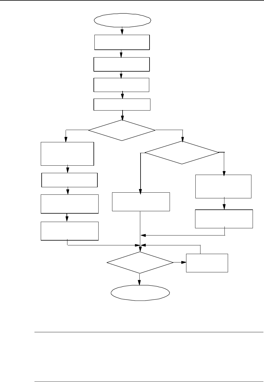
3.1 Installation Flow
According to different installations of the BTS major equipment, the installation of the
antenna and feeder system differs. The installation flow of the antenna and feeder
system is shown in Figure 3-1.
Installation Manual
iSiteC BTS3601C CDMA Base Station Hardware Installation
3 Installing RF Antenna and Feeder System
3-2
Install feeder, then
connect antenna with
feeder through jumper, and
get feeder grounded.
Install sealing window
for feeder.
Lead feeder indoor and
apply sealing window
upon feeder.
The installation
is done.
Do antenna and feeder pass
the testing?
NLocate the problem
and take actions.
Y
Assemble antenna
Install copper busbar
Install antenna support
Install antenna
Start to install
Connect feeder with
mini-MS
Want to connect mini-MS
with antenna through
jumper?
Y
Connect mini-MS with
antenna
Install feeder, then
connect antenna with
feeder through jumper, and
get feeder grounded.
Connect mini-
MS with feeder
N
Select the
installation mode
Indoor
installation Outdoor
installation
Figure 3-1 Installation flow of antenna and feeder system
&
Note:
The installation of antenna and feeder system is exemplified by the indoor installation of BTS. For the
antenna and feeder installation in case of BTS outdoor installation, please refer to the installation of the
antenna and feeder system of BTS indoor installation.
Installation Manual
iSiteC BTS3601C CDMA Base Station Hardware Installation
3 Installing RF Antenna and Feeder System
3-3
3.2 Installing Antenna Accessories
3.2.1 Installing Omni Antenna Accessories
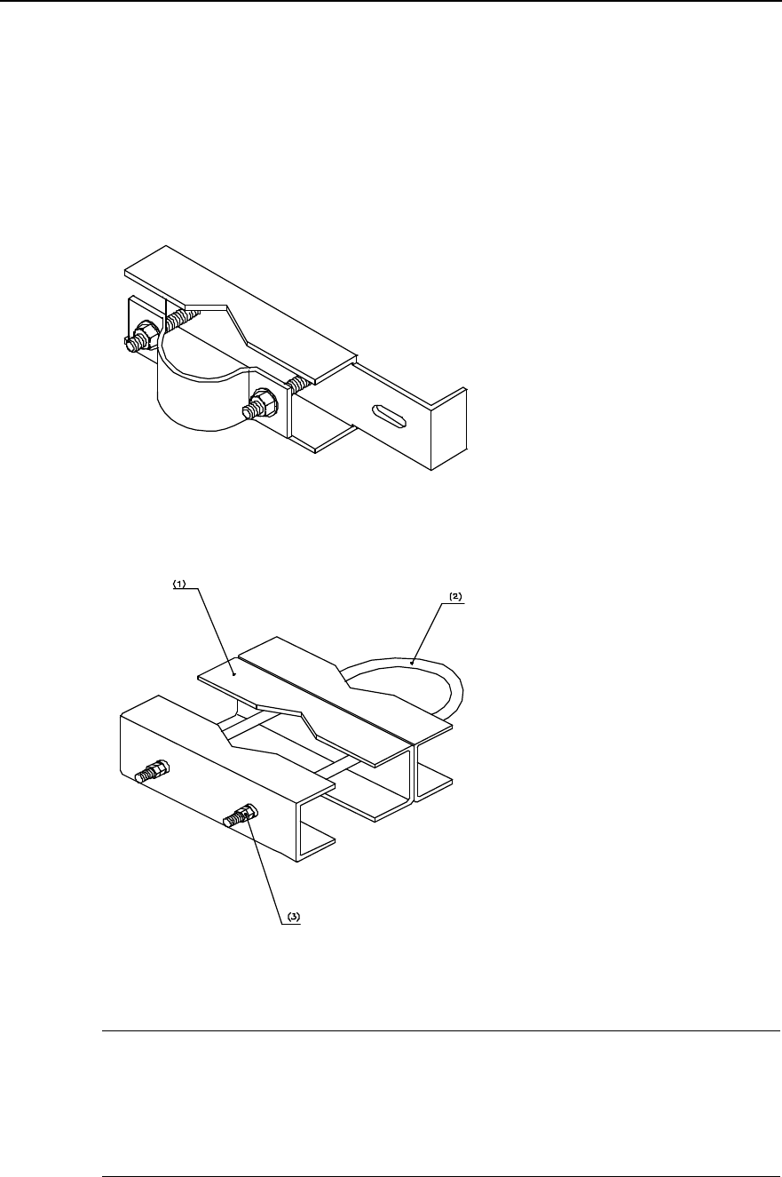
Accessories used to assemble the omni antenna are antenna fixing clip and jumper.
The omni antenna fixing clip is shown in Figure 3-2 and Figure 3-3.
Figure 3-2 Omni antenna fixing clip (1)
(1) Omni antenna joint (2) M12%580 U-bolts (3) Nut M12
Figure 3-3 Omni antenna fixing clip (2)
&
Note:
There are various types of fixing clips for the omni antenna, including the two shown in Figure 3-2 and
Figure 3-3 for reference. In practical installation, the fixing clips should be applied according to the actual
situations. The following takes the antenna fixing clip as shown in Figure 3-2 as an example.
Installation Manual
iSiteC BTS3601C CDMA Base Station Hardware Installation
3 Installing RF Antenna and Feeder System
3-4
The installation procedure of accessories is as follows:
1) Assemble the two fixing clips of the omni antenna with the part contacting the
antenna fastened so as to reduce the work on the tower or the building-top, as
shown in Figure 3-4.
(1)
(2)
(3)
(1)Omni antenna (2) Antenna jacket (3) Omni antenna fixing clip
Figure 3-4 Fixing omni antenna
2) Connect the jumper connector to the antenna connector and fasten it.
3) Perform waterproof and sealing treatment to the joint between the antenna and
the jumper. Please refer to Section 2.3.6 for the waterproof treatment.
&
Note:
Steps 2) and 3) can be completed on the tower or the building-top.
3.2.2 Installing Directional Antenna Accessories
Accessories used to assemble the directional antenna are antenna fixing clip (as
shown in Figure 3-5), tilt angle adjustment device (as shown in Figure 3-6), and jumper.
Installation Manual
iSiteC BTS3601C CDMA Base Station Hardware Installation
3 Installing RF Antenna and Feeder System
3-5
Figure 3-5 Directional antenna fixing clip
Figure 3-6 Directional antenna tilt angle adjustment device
The installation procedure of accessories is as follows:
1) First, determine the two fixed adjusting points on the top and bottom of the
antenna according to the label on the back of the antenna. The point on the top of
the antenna is for adjusting the pitch angle, and the point on the bottom for fixing
the antenna and its support.
2) Mount each accessory to its position according to the assembly diagram provided
by the vendor. All the accessories must be furnished with spring washers and plain
washers.
3) Jumper connection: Take off the jacket at the lower part of the antenna. Then
connect the jumper connector and the antenna connector and fasten them.
4) Perform waterproof treatment to the connector (the same method as that to the
connector between omni antenna and jumper).
Installation Manual
iSiteC BTS3601C CDMA Base Station Hardware Installation
3 Installing RF Antenna and Feeder System
3-6
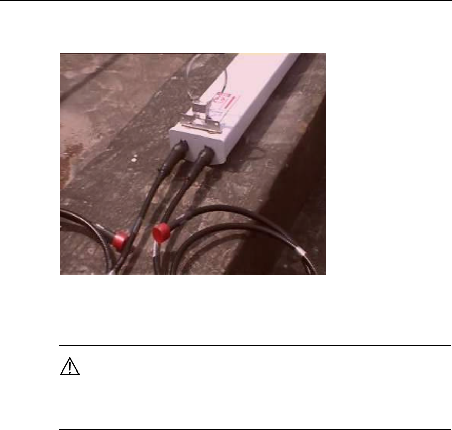
Figure 3-7 shows the connection between the directional antenna and jumper, and the
jumper connector after treatment.
Figure 3-7 Connection between directional antenna and jumper and jumper connector after treatment
Caution:
Antenna fixing clip and pitch angle adjustment device must be furnished with spring washers and plain
washers in correct installation sequence.
3.3 Installing Grounding Bar
Grounding copper bar is used to connect the PGND and working ground of the cabinet.
It should be installed both indoor and outdoor. In indoor installation, it is usually
mounted on the wall near the BTS; while in outdoor installation, it is usually mounted
near the BTS, yet its specific position is determined according to the actual situation.
The structure of grounding copper bar is shown in Figure 3-8.
Installation Manual
iSiteC BTS3601C CDMA Base Station Hardware Installation
3 Installing RF Antenna and Feeder System
3-7
(1)
330mm
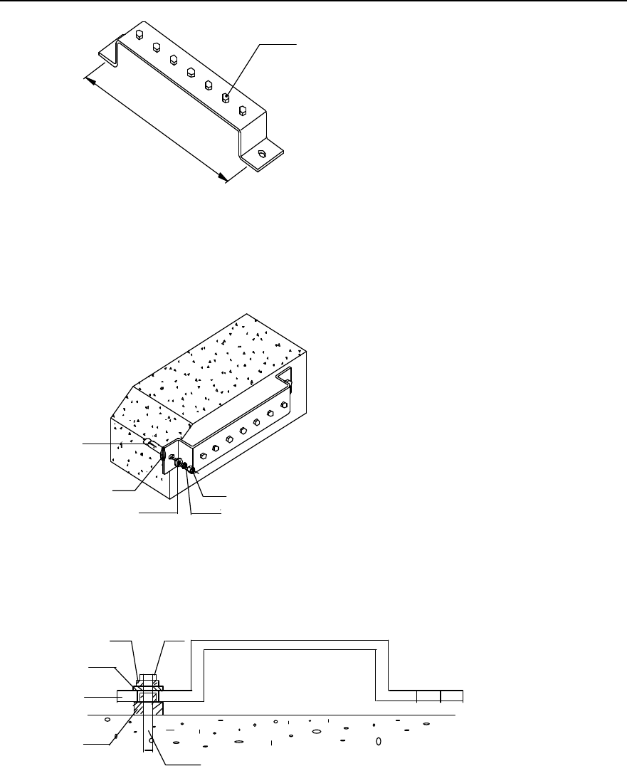
(1) M8 bolt
Figure 3-8 Structure of the grounding copper bar
The installation is shown in Figure 3-9 and Figure 3-10.
(1)
(2)
(3)
(4)
(5)
(1) Nut M12 (2) Spring washer v12 (3) Large plain washer
(4) Insulation washer (5) M12%80 exploded expansion bolt
Figure 3-9 Installing the grounding copper bar
(1)
(2)
(3)
(4)
(5)
(6) Wall
(1) Nut M12 (2) Spring washer v12 (3) Large plain washer
(4) Indoor grounding copper bar (5) Insulation washer (5) M12%80 exploded expansion bolt
Figure 3-10 Sectional view of grounding copper bar installation
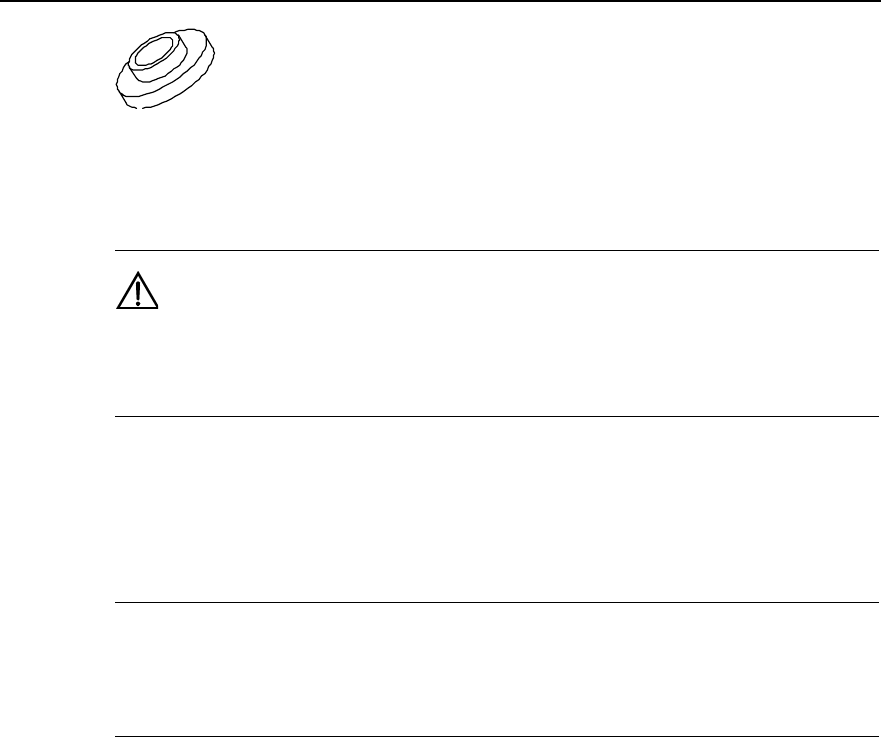
The insulation washer is shown in Figure 3-11.
Installation Manual
iSiteC BTS3601C CDMA Base Station Hardware Installation
3 Installing RF Antenna and Feeder System
3-8
Figure 3-11 Insulation washer
Caution:
Insulation washer should be furnished when the expansion bolt is installed. So the grounding copper bar is
insulated from the wall.
3.4 Installing Antenna Support
&
Note:
In non-turnkey project, the user should prepare the antenna support when preparing the environment.
Huawei is responsible for antenna support installation only in turnkey project.
There are a number of structures and types of antenna support. The following gives two
installation methods for antenna support as examples, namely, installing antenna
support on tower platform and on building-top.
3.4.1 Installing Support on Tower Platform
I. Antenna support structure
Figure 3-12 shows the antenna support installed on tower.
Installation Manual
iSiteC BTS3601C CDMA Base Station Hardware Installation
3 Installing RF Antenna and Feeder System
3-9
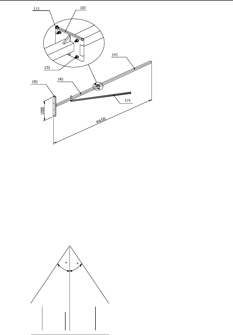
(1) M12%220 bolt (2) Joint soleplate (3) M12%45 bolt (4) Expansion arm
(5) Fixing arm (6) Whirling arm (7) Reinforcing arm
Figure 3-12 Structure of antenna support installed on tower
II. Installation requirements
1) Installation plane of the antenna support should be vertical to the horizontal plane.
2) Tower lightning arrester mast should be installed separately with the height
satisfying lightning protection requirements of all antennae. When the support
extends out of the tower platform, it should be ensured that the antenna is within
the protection range formed by 30° pitch angle of the lightning arrester apex, as
shown in Figure 3-13.
30 30
RX TX RX
Figure 3-13 Installing the lightning arrester
Installation Manual
iSiteC BTS3601C CDMA Base Station Hardware Installation
3 Installing RF Antenna and Feeder System
3-10
3) Make sure that the installation direction of the antenna support would not influence
the receiving (RX)/transmitting (TX) performance and direction adjusting of the
antenna.
4) If necessary, take suspension measures to avoid distortion of the antenna support
as it will be in use for a long time.
5) Whirling arm should be reinforced by reinforcing arm. The length of expansion arm
and whirling arm may be determined according to the onsite situation. The fracture
should be soldered with cover plate to avoid leaking water.
6) All the soldered parts should be secure enough without dry joint and open solder
point. The surface of the support should be covered by anti-rust silvery paint.
Better choose zinc-coated steel for the support.
III. Installation procedure
1) Install a fast pulley on the tower top. Use one or two lifting ropes to hoist the
support to the tower platform via the fixed pulley. Besides, a rope is needed to
control the upward direction of the support;
2) Determine the installation position of the antenna support on building-top
according to the antenna and feeder installation diagram in the engineering design
drawing.
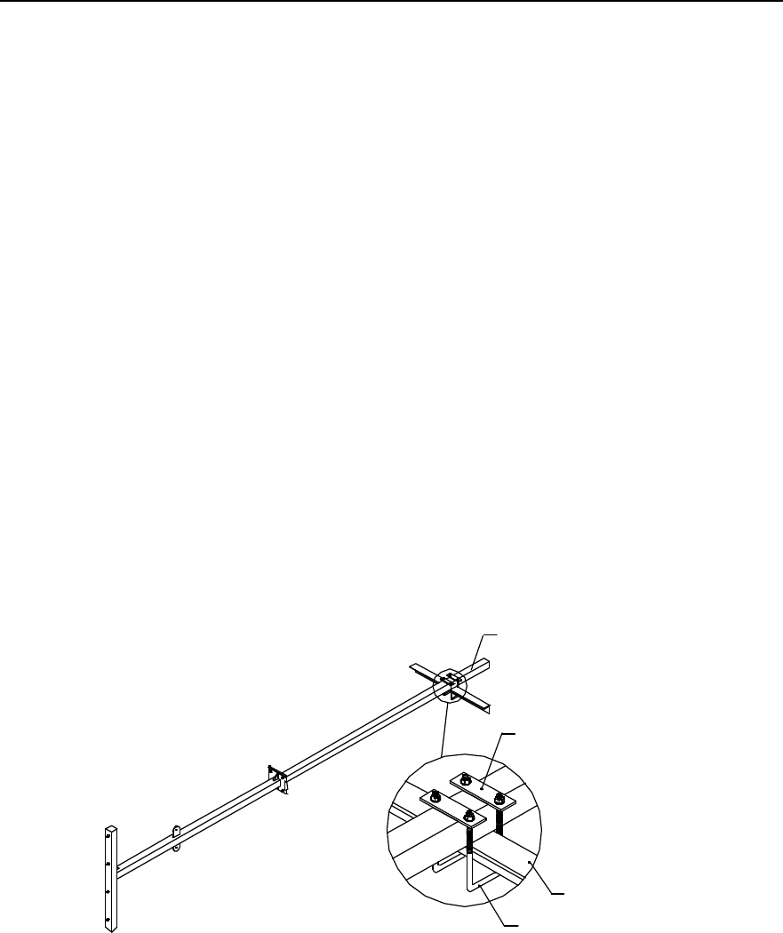
3) Fix the support on the tower with a U-shape fixing clip, as shown in Figure 3-14.
4) Connect the tower platform guardrail and joint soleplate with M12%45 bolt.
(1)
(2)
(3
)
(4)
(1) Expansion arm (2) Connecting arm (3) Tower beam (4) U-bolt
Figure 3-14 Installing the antenna support on tower
3.4.2 Installing Support on Building-top
I. Antenna support structure
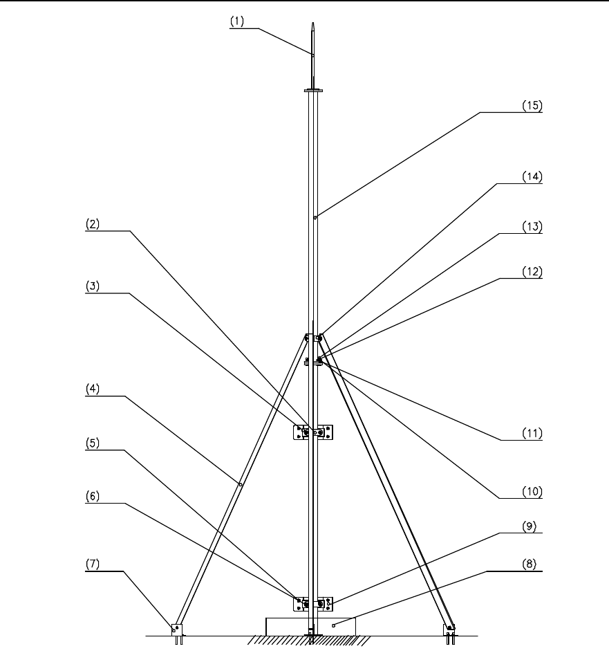
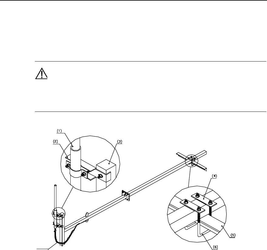
Figure 3-15 illustrates the antenna support installed on building-top.
Installation Manual
iSiteC BTS3601C CDMA Base Station Hardware Installation
3 Installing RF Antenna and Feeder System
3-11
(1) Antenna lightning arrester (2) 180° joint (3) V-joint (4) Reinforcing arm
(5) Expansion M12%120 bolt (6) Washer v12 (7) Anchor (8) Covered with
concrete
(9) Mounting plate (soldered) (10) Spring washer v10 (11) Washer v10 (12) Nut M10
(13) M10%45 bolt (14) 120° joint (15) Mainstay support of
the antenna
Figure 3-15 Structure of antenna support installed on building-top
II. Installing requirements
1) The installation position of joint for reinforcing arm should not affect the adjustment
of antenna direction and pitch angle.
2) Antenna support must be vertical to the horizontal plane.
Installation Manual
iSiteC BTS3601C CDMA Base Station Hardware Installation
3 Installing RF Antenna and Feeder System
3-12
3) Antenna support on building-top must be equipped with lightning arrester, and the
support should be connected to the building lightning-protection network.
4) The surface of the support and all the soldered parts should be covered by
anti-rust paint. All the soldered parts should be secure enough without dry joint
and open solder point.
III. Installing the support on building-top without parapet
1) Hoist the support to the building-top.
2) Determine the installation position of the antenna support on building-top
according to the antenna and feeder installation diagram in the engineering design
drawing.
3) Solder the lightning arrester on the mainstay support of the antenna (with the axes
aligned).
4) As shown in Figure 3-16, fix the base of the antenna on the building-top vertically
with eight M10%45 expansion bolts.
(1) Hexagonal M10%50 bolt (2) Joint for reinforcing
arm (3) M10%50 exploded expansion
bolt
(4) Plastic foot for antenna mainstay support (5) Mainstay support
of the antenna
Figure 3-16 Installing the antenna support base
5) Mainstay support needs to be reinforced with reinforcing arm whose length is
determined according to that of the mainstay support. As shown in Figure 3-17,
the reinforcing arm is connected to the mainstay support through its joint. Connect
the anchors to the reinforcing arm and fix the anchors of each reinforcing arm on
Installation Manual
iSiteC BTS3601C CDMA Base Station Hardware Installation
3 Installing RF Antenna and Feeder System
3-13
the building-top floor with two M10%45 expansion bolts. Make sure the connection
of the reinforcing arms will not be twisted.
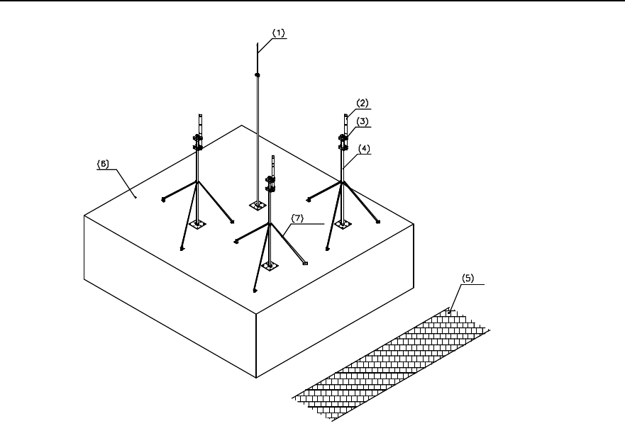
6) As shown in Figure 3-17, connect mainstay support 2 with mainstay support 1
tightly with six M10%80 bolts.
8
(1) Antenna lightning arrester (2) Mainstay support 2 (3) Reinforcing arm (4) Mainstay support 1
(5) Plastic root for support (6) Anchor of reinforcing
arm (7) Soldered parts (8) M10%80 bolt
Figure 3-17 Installing the antenna support
7) There are such cases that the building-top antenna support is not soldered with
outdoor cabling rack; or soldered but the cabling rack is not connected with the
lightning-protection network of the building. In this case, connect the base of the
antenna support to the lightning-protection network of the building with a
lightning-protection connecting bar (the lightning-protection connecting bar is the
installation parts for outdoor cabling rack).
8) Cover all the soldered parts and the support base with anti-rust paint.
9) Base of the building-top antenna support, anchors of the reinforcing arm and the
expansion bolts connected with the floor should all be covered with concrete for
protection.
Installation Manual
iSiteC BTS3601C CDMA Base Station Hardware Installation
3 Installing RF Antenna and Feeder System
3-14
IV. Installing the support on building-top with parapet
If there is parapet around the building-top, and it is inconvenient to install the support on
the building-top, just mount the support on the parapet. Figure 3-18 illustrates the
antenna support fixing clip mounted on the parapet.
(1) Expansion M 12%120 bolt (2) V-joint (3) 180° joint
(4) M12×140 bolt (5) Mounting plate
Figure 3-18 Fixing clip of antenna support installed on parapet
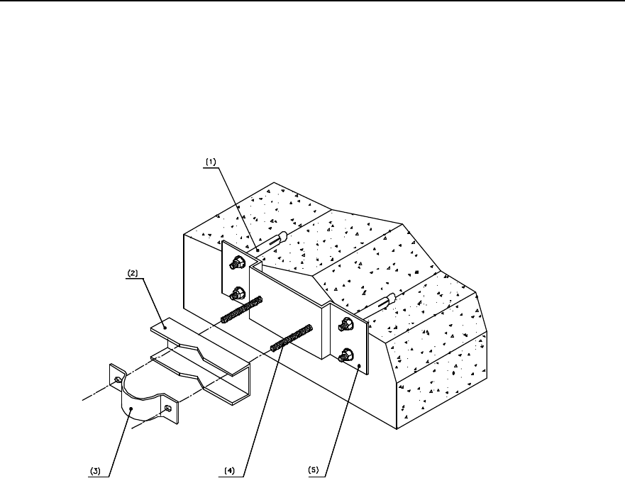
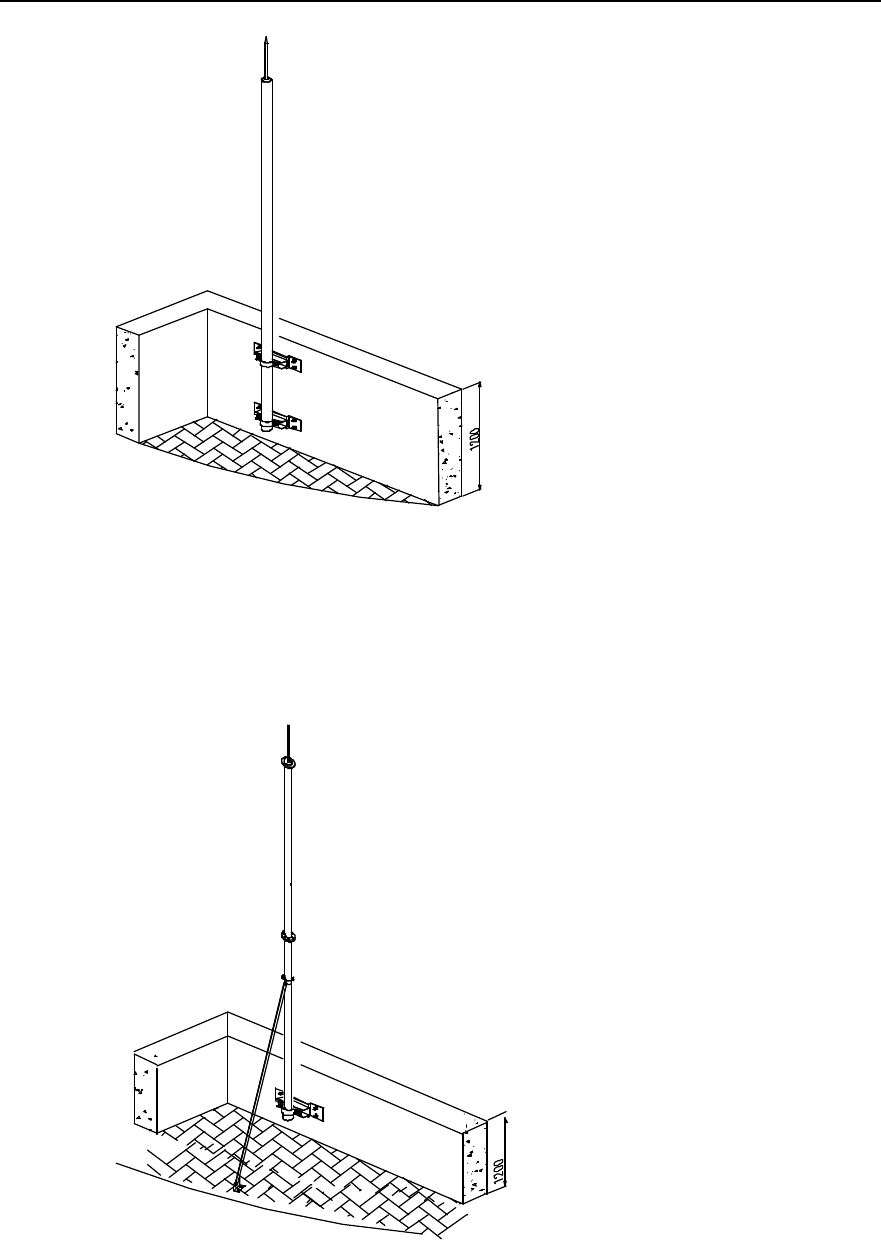
In the case the parapet is not shorter than 1200mm, fix the two fixing points of the
support on the parapet with expansion bolts, as shown in Figure 3-19.
Installation Manual
iSiteC BTS3601C CDMA Base Station Hardware Installation
3 Installing RF Antenna and Feeder System
3-15
Figure 3-19 Antenna support fixed on parapet (with parapet not shorter than 1200mm)
In the case the parapet is shorter than 1200mm, fix one fixing point of the mainstay
support to the parapet with expansion bolt, and the other fixing point to the building, as
shown in Figure 3-20.
小
于
Figure 3-20 Antenna support fixed on parapet (with parapet shorter than 1200MM)
Installation Manual
iSiteC BTS3601C CDMA Base Station Hardware Installation
3 Installing RF Antenna and Feeder System
3-16
3.5 Installing Antenna
3.5.1 Antenna Facade
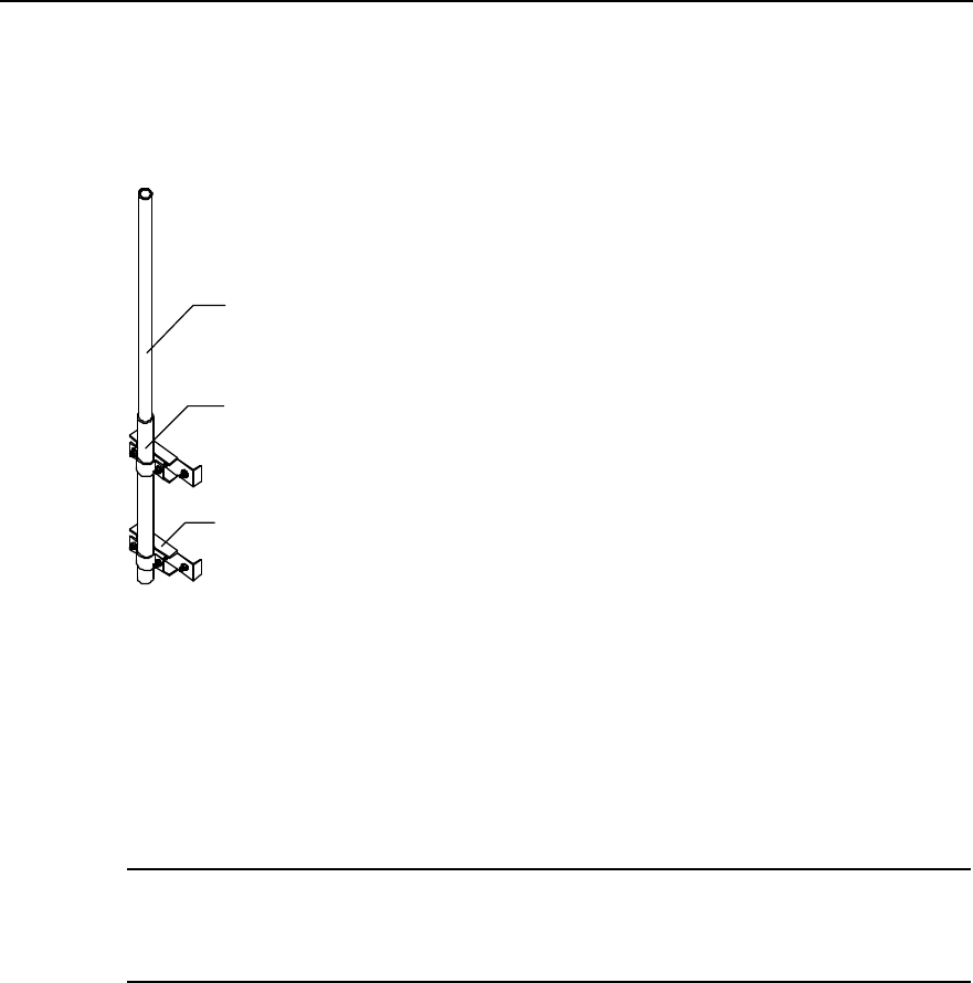
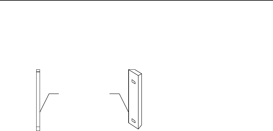
The façade of omni antenna and directional antenna is shown in Figure 3-21.
(1)
(2)
(1) Omni antenna (2) Directional antenna
Figure 3-21 Antennae
3.5.2 Hoisting Antenna
Tie a knot at both ends of the antenna with a rope. Persons both on the tower and down
the tower cooperate to hoist the antenna to its position. The persons down the tower
should strain on the rope so as to avoid damage to the antenna due to clashing
between the antenna and the tower body or the building.
3.5.3 Installing Omni Antenna
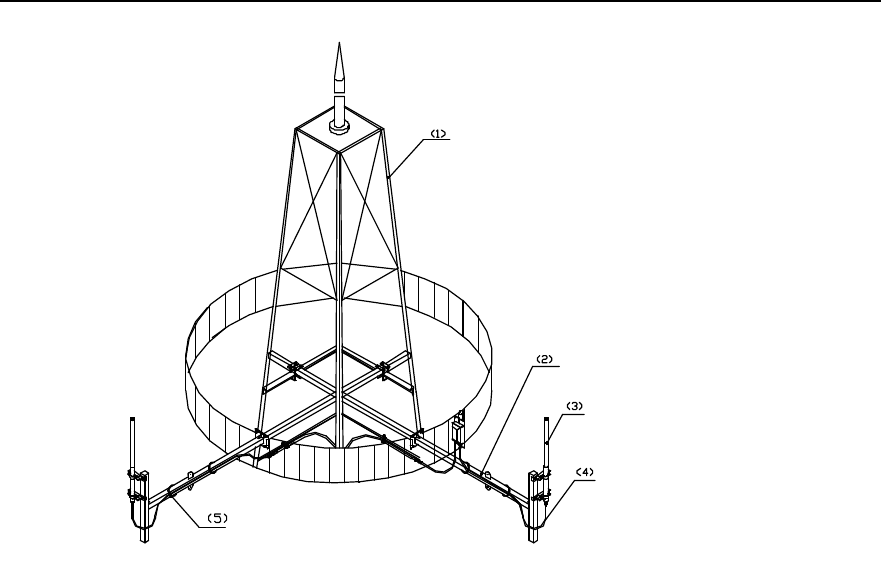
Installation of the omni antenna on the tower platform is shown in Figure 3-22.
Installation Manual
iSiteC BTS3601C CDMA Base Station Hardware Installation
3 Installing RF Antenna and Feeder System
3-17
(1) Tower (2) Tower-top antenna support (3) Omni antenna
(4) Jumper waterproof elbow (5) Cable tie
Figure 3-22 Installing the omni antenna on tower platform
I. Installation requirements
l When installing the omni antenna on the tower, make sure the antenna is in the
protection range of lightning arrester on the tower. The distance between the omni
antenna and the tower body should be left at least 1.5m.
l The antenna axis should be vertical to the horizontal plane with error less than !1°.
l The TX and RX antenna of omni antenna can be installed on one antenna support,
or be separately installed. The specified installation position should be determined
according to the engineering design drawing.
II. Installation procedure
1) Make the feeding point of the antenna facing down and the jacket near the
mainstay support. The top of the jacket should be on the same level or a little bit
higher than the top of the support.
2) As shown in Figure 3-23, secure the antenna fixing clip and the mainstay support
properly to ensure its load bearing and wind resistibility. It should not be too tight to
damage the jacket of the antenna.
3) Check whether the antenna axis is vertical to the horizontal plane with angle tester.
If the error is equal to or greater than !1°, adjust the antenna axis and then fasten
it.
4) Make waterproof elbow at the antenna connector.
Installation Manual
iSiteC BTS3601C CDMA Base Station Hardware Installation
3 Installing RF Antenna and Feeder System
3-18
5) Route the antenna jumper with natural jumper curves of proper angle. Generally, it
is required that the radius of the curves be 20 times larger than the jumper
diameter and the jumper be bound to the steel rack of the tower along the support
crosspiece with black cable tie.
Caution:
The cable ties should be bound toward the same direction with a margin of 5~10mm to avoid the ties fall off
when temperature changes.
(7)
(1) Antenna (2) Joint (3) Fixing arm (4) Connecting arm
(5) Tower beam (6) U-bolt (7) Jumper waterproof elbow
Figure 3-23 Installing the omni antenna
Installation of omni antenna on building-top support is similar to that on tower side. The
installation is shown in Figure 3-24.
Installation Manual
iSiteC BTS3601C CDMA Base Station Hardware Installation
3 Installing RF Antenna and Feeder System
3-19
(1) Antenna lightning arrester (2) Antenna (3) Omni antenna fixing clip (4) Mainstay support of
antenna
(5) Road surface (6) Building-top (7) Reinforcing arm
Figure 3-24 Installing the omni antenna on building-top support
3.5.4 Installing Directional Antenna
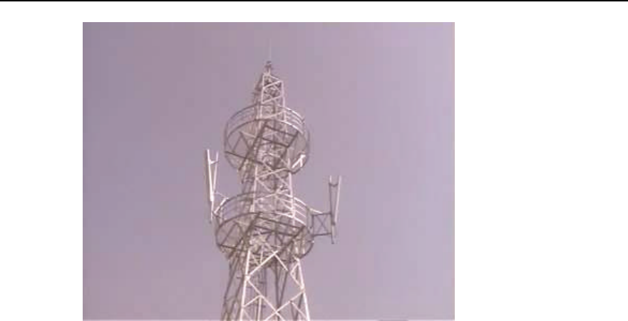
The installation of directional antenna on the tower side is shown in Figure 3-25.
Installation Manual
iSiteC BTS3601C CDMA Base Station Hardware Installation
3 Installing RF Antenna and Feeder System
3-20
Figure 3-25 Installing the directional antenna on the tower side
I. Installation requirements
l When installing the directional antenna on the tower, make sure the antenna is in
the protection range of lightning arrester on the tower. The antenna should stretch
out of the tower body for at least 1m.
l Waterproof elbow must be made to the antenna jumper.
II. Installation procedure
1) Determine the installation direction of the antenna according to the engineering
installation drawing.
2) Fix the antenna onto the main supporting post. The fixing tightness should be right
enough for weight bearing and wind resistance. Looseness may cause loose
connection while too much tension may damage the antenna sheathing;
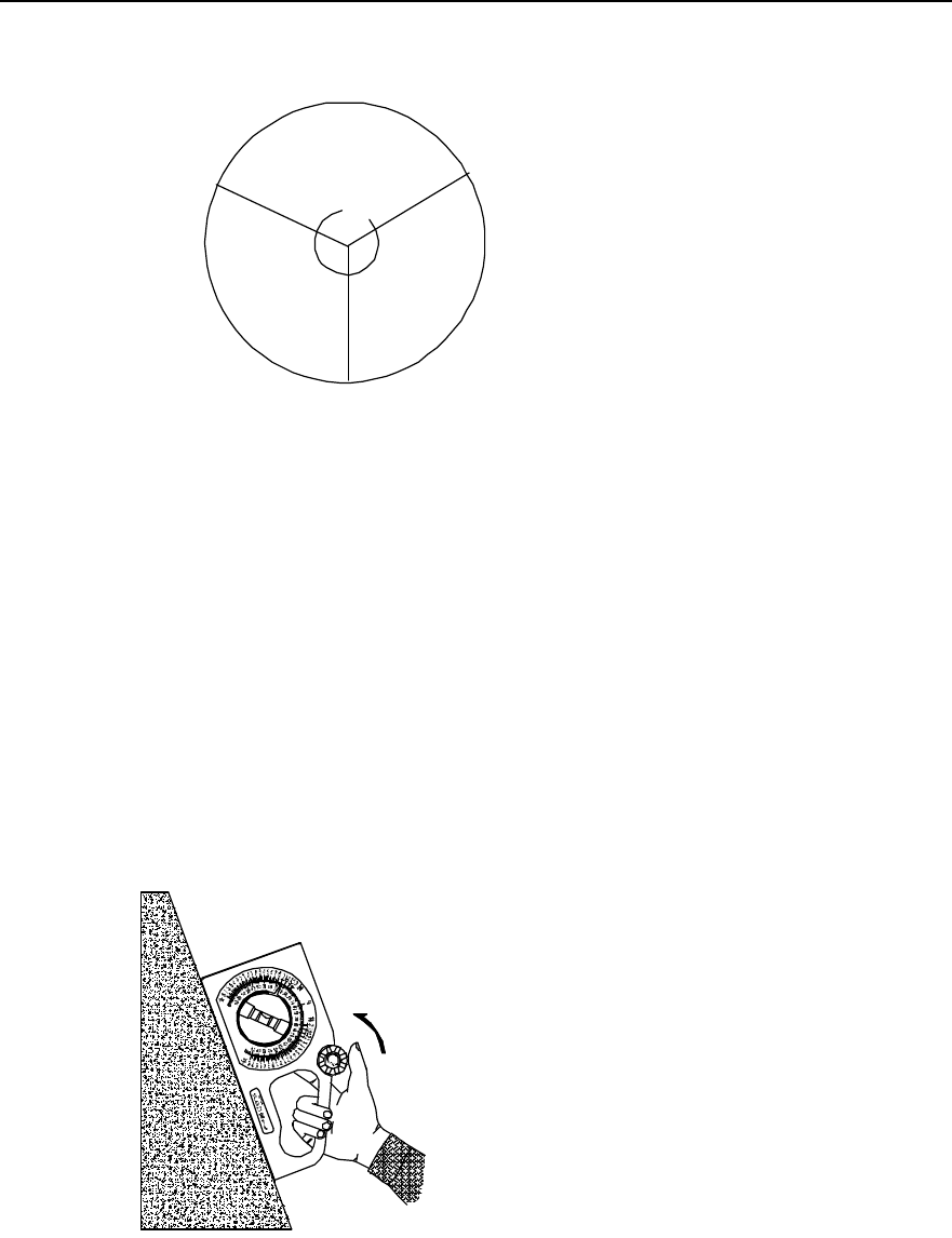
3) Adjust the antenna azimuth angle: Determine the antenna azimuth angle with a
compass according to the engineering design documents. Normally, Starting from
the north clockwise, the area covered by the first antenna is sector 1. Sector 2 lies
in the clockwise 120° direction and sector 3 in the next clockwise 120° direction, as
shown in Figure 3-26. While adjusting the azimuth, turn the antenna azimuth
slightly till it satisfies the design index value with the azimuth error not greater than
5°.
Installation Manual
iSiteC BTS3601C CDMA Base Station Hardware Installation
3 Installing RF Antenna and Feeder System
3-21
Sector 1
North
120˙
120˙
Sector 2
Sector 3
Figure 3-26 Correspondence between directional antenna azimuth and sector
4) Tighten up the lower fixing clip of the antenna till it cannot be moved by hand.
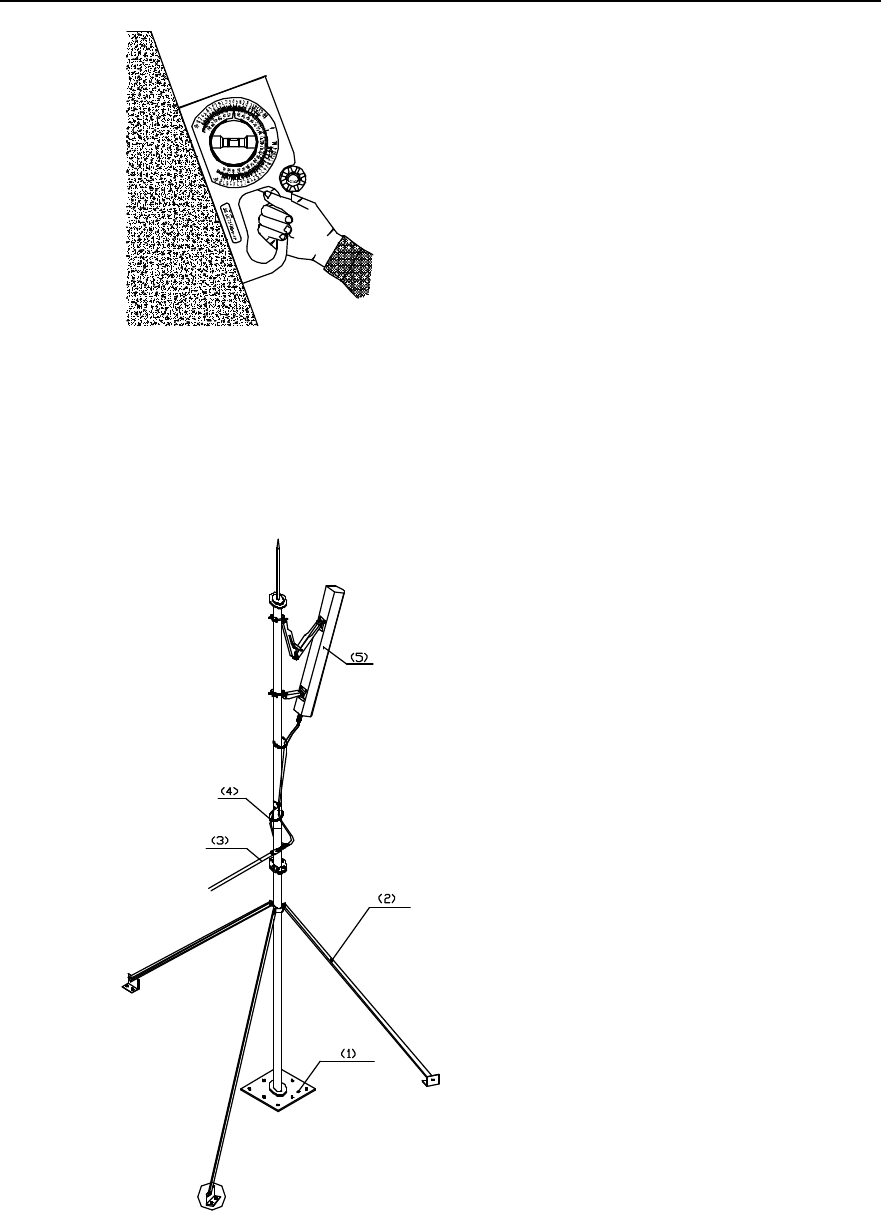
5) Adjust the antenna pitch angle: For the directional antenna whose mounting hole
corresponds to its pitch angle, install it via its mounting hole directly. Make sure the
supporting post of its support is kept strictly perpendicular to the ground during the
installation. Adjust the pitch angles of other antennae in the following way:
l Determine the antenna pitch angle using an inclinometer.
l Turn the antenna slightly and adjust the pitch angle till it satisfies the engineering
design index value. Generally the error of the pitch angle should be Ÿ0.5°.
l Tighten up the upper fixing clip of the antenna till it cannot be moved by hand;
Use the inclinometer in the way as shown in Figure 3-27 and Figure 3-28.
Figure 3-27 Pitch angle of the antenna before being adjusted by the inclinometer
Installation Manual
iSiteC BTS3601C CDMA Base Station Hardware Installation
3 Installing RF Antenna and Feeder System
3-22
Figure 3-28 Pitch angle of the antenna after being adjusted by the inclinometer
6) Make waterproof elbow for the antenna jumper and route the jumper.
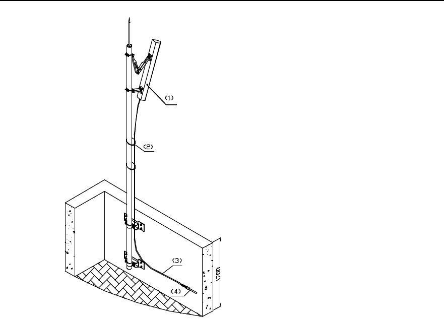
Installation of directional antenna on building-top support is similar to that on tower side.
The installation is shown in Figure 3-29 and Figure 3-30.
(1) Plastic root of support (2) Reinforcing arm (3) Feeder
(4) Cable tie (5) Antenna
Figure 3-29 Installing the directional antenna on building-top (without parapet)
Installation Manual
iSiteC BTS3601C CDMA Base Station Hardware Installation
3 Installing RF Antenna and Feeder System
3-23
(1) Antenna (2) Cable tie (3) Jumper (4) Feeder
Figure 3-30 Installing the directional antenna on building-top support (with parapet not shorter than
1200mm)
3.6 Installing Feeder Window
3.6.1 About Feeder Window
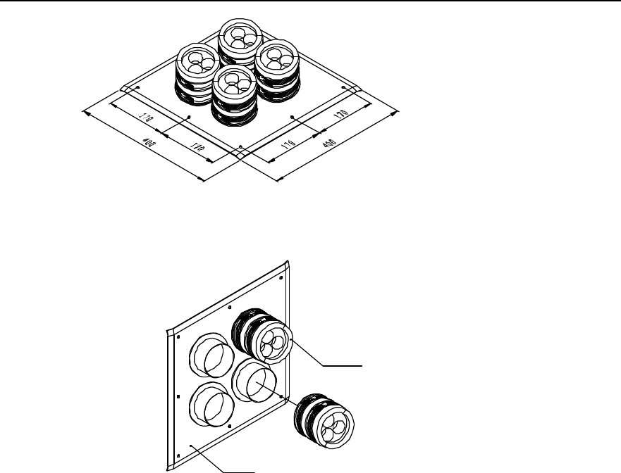
There are two types of feeder windows: 12-hole feeder window and 27-hole feeder
window. The former is used most frequently. Figure 3-31 shows its structure,
dimensions and its connection with the sealing gland. The following gives the
installation method of 12-hole feeder window only.
Installation Manual
iSiteC BTS3601C CDMA Base Station Hardware Installation
3 Installing RF Antenna and Feeder System
3-24
(1)
(2)
(1) Sealing packing ring of feeder window (2) Feeder window board
Figure 3-31 Structure and dimensions of feeder window
3.6.2 Installing Feeder Window
Feeder window is usually installed outdoors near and above the cabling rack. If feeders
enter the equipment room from building-top, the feeder window should be installed on
building-top.
Installation procedure is as follows:
1) Determine the indoor installation position for the feeder window according to the
engineering design drawing and the dimensions of the window. Mark the positions
for expansion bolt holes and for feeder window cavity on the wall.
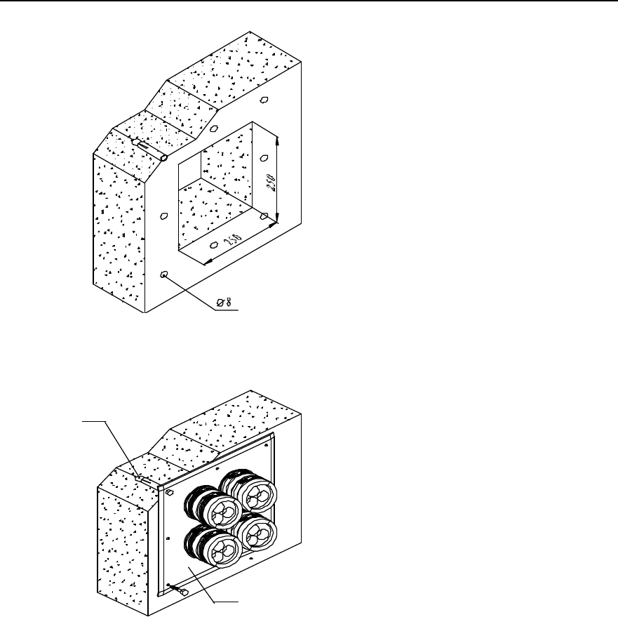
2) As shown in Figure 3-32, drill a square cavity of 250mm % 250mm on the wall, then
drill 8 holes for expansion bolts using a percussion drill.
3) As shown in Figure 3-33, secure the feeder window board with expansion bolts.
When mounting the expansion bolts, note the sequence of spring washer and
plain washer. The sealing gasket and sealing gland may be mounted when
leading the feeder indoor.
Installation Manual
iSiteC BTS3601C CDMA Base Station Hardware Installation
3 Installing RF Antenna and Feeder System
3-25
Figure 3-32 Mounting holes for feeder window
Indoor
Outdoor
(1)
(2)
(1) M8%80 exploded expansion bolt (2) Feeder window board
Figure 3-33 Installing feeder window
3.7 Installing Feeders
3.7.1 Cutting Feeder
The feeders can be cut prior to or after feeder hoisting.
1) Determine the length of the feeders required in each sector according to the
engineering design drawing;
2) Cut the feeder by the determined length, leaving a margin of 1m~2m. When
cutting the feeder, do not bend it and prevent it from being rolled over or stepped
on by vehicles or pedestrians;
Installation Manual
iSiteC BTS3601C CDMA Base Station Hardware Installation
3 Installing RF Antenna and Feeder System
3-26
3) Attach the corresponding labels to both ends of the feeder after cutting a piece.
3.7.2 Hoisting Feeder
1) Wrap the feeder end in a piece of gunny cloth (or antistatic bag) after the
corresponding connector is completed. Bind the cloth up using a rope or a binding
tape;
2) Knot the lifting rope at the point about 0.4m away from the feeder end and tie
another knot at the point about 4.4m away from the feeder end to prepare for
feeder hoisting, as shown in Figure 3-34.
4000
400
(1)
(2)
(1) Lifting rope (2) Feeder
Figure 3-34 Protection of feeder connector
3) Hoist the feeder to the tower platform. No violent hoisting is allowed so as to avoid
damage to the feeder skin due to possible collision with the building or the tower.
In the meantime, take care of your safety.
4) Fix the upper end of the feeder in a proper position by multiple-point fastening lest
that the feeder fall from the tower. However, it should not be too close to the
antenna, as shown in Figure 3-35. Select 1-for-1 fixing clip or 1-for-3 fixing clip as
is required, as shown in Figure 3-36.
Installation Manual
iSiteC BTS3601C CDMA Base Station Hardware Installation
3 Installing RF Antenna and Feeder System
3-27
Figure 3-35 Feeder upper end fixed on tower
2
(1) (2)
(2)
(1) 1-for-1 fixing clip (2) 1-for-3 fixing clip
Figure 3-36 Feeder fixing clip
5) Connect the jumper between antenna and feeder and perform waterproof and
encapsulation treatment to the connectors. Attach a temporary label at the point
10cm away from the jumper end.
3.7.3 Routing Feeder
Routing procedure:
1) Design the feeder arrangement according to the sector requirement in the
engineering design. Determine the arrangement and lead-in plan. Usually, there is
one row or column of feeders in a sector arranged in the same sequence.
2) Route the feeders according to the planned sequence.
3) Arrange the feeders neatly while fixing them onto the tower or the cabling rack with
fixing clips. Meanwhile, mount the feeder grounding clip and attach feeder labels.
Installation Manual
iSiteC BTS3601C CDMA Base Station Hardware Installation
3 Installing RF Antenna and Feeder System
3-28
3.7.4 Affixing Feeder Labels
I. Label format
Figure 3-37 illustrates the standard nameplate used as both indoor and outdoor labels.
Figure 3-37 RF antenna and feeder label
II. Label position
1) BTS indoor installation mode
Feeder labels can be affixed in three positions, which are (from the top down):
l 0.3m to the outdoor feeder connector;
l Outside the feeder entrance to the feeder window;
l 0.3m to the indoor feeder connector.
2) BTS outdoor installation mode
Feeder labels can be affixed in two positions, which are (from the top down):
l 0.3m to the outdoor feeder connector;
l 0.3m to the front end connecting the BTS.
3.7.5 Grounding Feeders
Installation of feeder grounding clip and routing of feeders are carried out
simultaneously. When grounding the feeders, ground the feeder skin with the lightning
protection grounding clip. The grounding cable led out should be connected to the
Installation Manual
iSiteC BTS3601C CDMA Base Station Hardware Installation
3 Installing RF Antenna and Feeder System
3-29
protection grounding bar directly. The following gives description of feeder grounding
points in different installation modes.
I. BTS outdoor installation mode
l Within the range of 1m~2m under the antenna;
l The front end connecting the BTS.
Caution:
1) When soft jumper is adopted for the feeder and the feeder is not longer than 5m, the shielding covering
of the feeder may be grounded at the front end connecting the BTS.
2) If the feeder is longer than 60m, feeder grounding clips should be applied in the middle of the feeder,
with the clip spacing of 20m.
II. BTS indoor installation with the outdoor feeder longer than 20m
l Within the range of 1m~2m under the antenna;
l Within 1m range of the mast or of where the feeder is led from the tower platform;
l At the outer side of the feeder window where the feeder enters the equipment
room (connecting to outdoor PGND bar).
l Close to the indoor protection grounding bar after it enters the equipment room.
Others:
l If the feeder is longer than 60m, feeder grounding clips should be applied in the
middle of the feeder, with the clip spacing of 20m.
l If the feeder is led into the room after being routed for a stretch of distance on the
building-top, and the distance exceeds 20m, a feeder grounding clip should be
applied on building-top.
l For the feeder that enters the room from the building-top along the wall, if a cabling
rack is used, the cabling rack should also be grounded.
l Feeder grounding cable should be routed toward the BTS antenna and feeder port
along the antenna. The included angle between the feeder grounding cable and
the feeder should not be greater than 15°. The feeder grounding clip should be
directly secured to the steel board on the nearby tower body.
III. BTS indoor installation with the outdoor feeder shorter than 20m
l Within the range of 1m~2m under the antenna;
l At the outer side of the feeder window where the feeder enters the equipment
room (connecting to outdoor PGND bar);
l Close to the indoor PGND bar after it enters the equipment room.
Installation Manual
iSiteC BTS3601C CDMA Base Station Hardware Installation
3 Installing RF Antenna and Feeder System
3-30
Caution:
1) When soft jumper is adopted for the feeder and the feeder is not longer than 10m, the shielding covering
of the coaxial soft jumper may be grounded at two points, i.e., below the antenna and indoor.
2) When soft jumper is adopted for the feeder and the feeder is not longer than 5m, the shielding covering
of the coaxial soft jumper may be grounded at one point indoor.
3.7.6 Leading Feeder into Equipment Room
I. Feeder arrangement principle
l There are 4 big holes in a 12-hole feeder window, and 3 small holes in each big
hole. One feeder can run through a small hole.
l The feeders should be arranged in sequence (i.e. clockwise or counter-clockwise)
in the three small holes of the same big hole.
l The arrangement of feeders in the feeder window should facilitate system
expansion. The original arrangement of feeders should not be changed during
system expansion. It is permitted to add feeders to the feeder window and change
the jumper connection on the cabinet top only.
l The arrangement of feeders in the feeder window should facilitate the routing of
feeders on the cabling rack and the connection of feeders with the cabinet top. The
feeders should be parallel to each other without any cross.
l The length of the feeder entering the feeder window should be 30cm~50cm. If
there is an indoor cabling rack, the feeder can be fixed with feeder clip. If not, the
feeder may be hanged in air.
Caution:
The minimum feeder curving radius should not be less than 20 times of the feeder diameter.
There should be no cross of the feeder when it is routed along the cabling rack and tower cabling ladder.
And there should be no crossing or overlapping of the feeder entering the equipment room. Therefore, it is
required to get an idea of the feeder routing prior to feeder distribution. It is best to draft the actual feeder
routing on paper to avoid rework due to feeder crossing.
II. Procedure
1) Make waterproof elbow for the feeder at the outer side of the feeder window.
Installation Manual
iSiteC BTS3601C CDMA Base Station Hardware Installation
3 Installing RF Antenna and Feeder System
3-31
2) Direct the feeders into the equipment room via the feeder window. The
corresponding personnel inside the equipment room should guide the operation
so as to avoid damage to equipment in the room.
3) Mount sealing gasket and sealing gland. Place the hole for filling in glue on the
sealing gland facing upward when mounting the sealing gland.
4) Cut the feeders correctly according to the design requirements.
5) Make the indoor feeder connector.
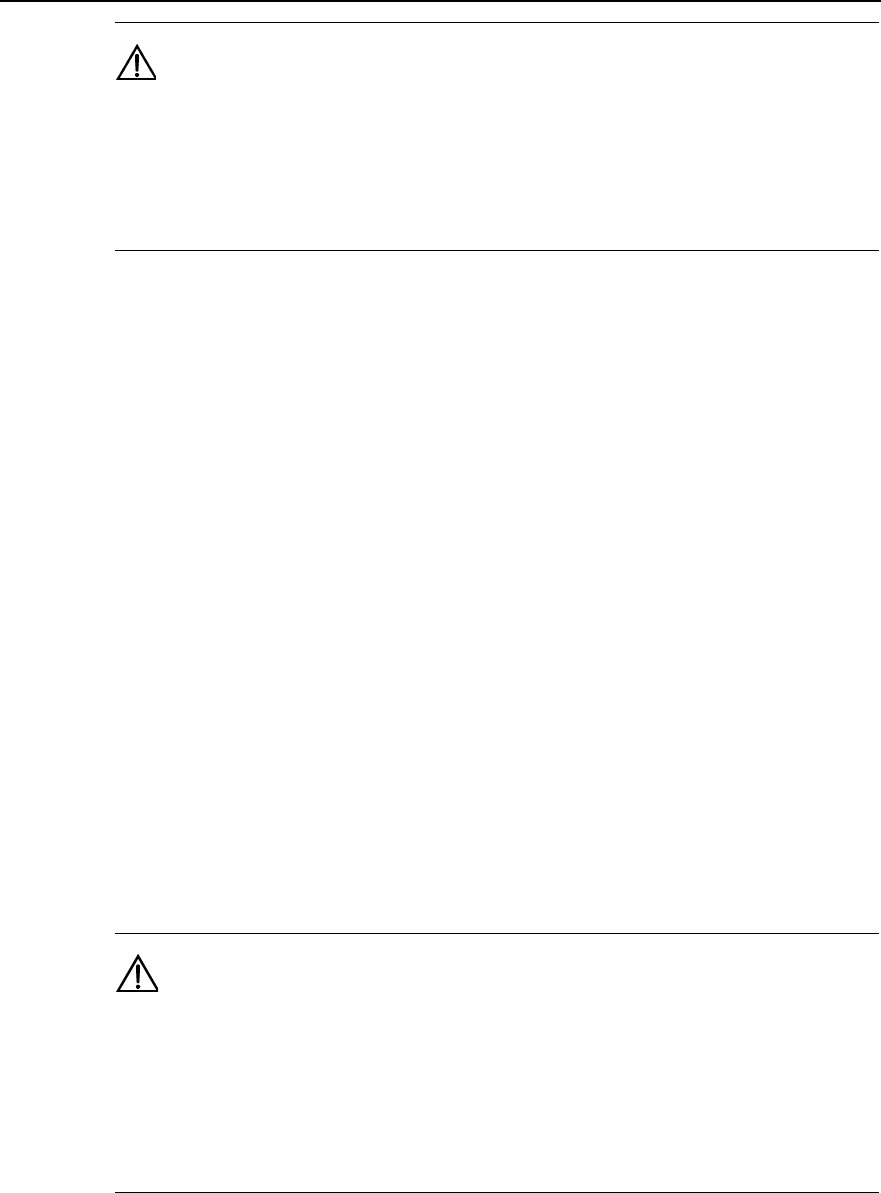
6) Encapsulate the feeder window and the unused holes with adhesive tape, plaster
and glass cement, as shown in Figure 3-38.
Figure 3-38 Encapsulation treatment of the feeder window after feeder enters the equipment room
&
Note:
If the feeder needs to run though the window glass, remove the glass first. Cut a corner of proper size of
the glass and then use rubber or adhesive tape to protect the edge, in order to avoid the feeder being cut.
Measures should be taken to prevent rain after the feeder runs through the glass, that is, seal the
connection between the glass and the feeder with glass cement.
3.7.7 Connecting Feeder and BTS
The feeder and BTS should be connected with 1/2 jumper. Feeder connector at BTS
side has already been connected during the installation of major equipment. Just
connect the feeder and jumper. In the case of outdoor installation of BTS, 3-layer
waterproof treatment should be performed in addition.

Installation Manual
iSiteC BTS3601C CDMA Base Station Hardware Installation
3 Installing RF Antenna and Feeder System
3-32
3.8 System Testing
Use the Site Master to test the antenna and feeder system. Test the standing wave ratio
(SWR) of the feeders. The SWR should be smaller than 1.5 in engineering, yet the
SWR of the antenna and feeder system newly set up generally should be smaller than
1.3 (the corresponding return loss is 18dB).
For the usage of the Site Master, please refer to relevant operation instructions.

Installation Manual
iSiteC BTS3601C CDMA Base Station Table of Contents
i
Table of Contents
4 Installing Satellite Synchronization Antenna and Feeder System......................................4-1
4.1 Installing GPS Antenna and Feeder System................................................................4-1
4.2 Installing GPS Antenna ..............................................................................................4-2
4.2.1 Requirements for Installation Position................................................................4-2
4.2.2 Installing GPS Antenna Support........................................................................4-3
4.2.3 Installing Antenna ............................................................................................4-7
4.3 Installing GPS Feeder ................................................................................................4-8
4.3.1 Routing Feeder ................................................................................................4-8
4.3.2 Installing Lightning Arrester ..............................................................................4-9
4.3.3 Grounding Requirement .................................................................................4-11
4.3.4 Feeder Label .................................................................................................4-13

Installation Manual
iSiteC BTS3601C CDMA Base Station Hardware Installation
4 Installing Satellite Synchronization Antenna and Feeder System
4-1
4 Installing Satellite Synchronization Antenna and
Feeder System
This chapter introduces the installation of satellite synchronization antenna and feeder
system taking GPS as an example. In practical installation, it can be performed
simultaneously with that of RF antenna and feeder system.
This chapter will not cover the same contents with the installation of RF antenna and
feeder system. Instead, it focuses on the differences between the installations of the
two systems.
4.1 Installing GPS Antenna and Feeder System
The installation of GPS antenna and feeder system is basically the same with that of
RF antenna and feeder system. The major differences lie between the GPS antenna
and the RF antenna. In addition, GPS antenna and feeder installation includes the
installation of antenna-side and equipment-side lightning arresters. The procedure is:
1) Check the installation environment of GPS antenna and feeder system.
2) Get familiar with the engineering design documents and determine the installation
scheme.
3) Install antenna support.
4) Install antenna.
5) Connect outdoor jumpers.
6) Install antenna-side lightning arrester.
7) Prepare the connectors of feeders, route the outdoor feeders and attach labels on
them.
8) Mount grounding clips for feeders.
9) Install equipment-side lightning arrester;
10) Prepare, route and bind indoor jumpers, and attach labels on them.
11) Inspect the project installation.
&
Note:
The installation of GPS antenna and feeder system can be performed simultaneously with that of RF
antenna and feeder system. The specific installation process can be adjusted according to the actual
configuration and environment.
Installation Manual
iSiteC BTS3601C CDMA Base Station Hardware Installation
4 Installing Satellite Synchronization Antenna and Feeder System
4-2
4.2 Installing GPS Antenna
4.2.1 Requirements for Installation Position
The installation position of GPS antenna should have a broad vision without high
buildings around, and as far as possible from the compact accessory buildings on the
building-top. The available area of the plane for installing GPS antenna should be as
big as possible. And the antenna should be vertically erected with a visual angle
greater than 90°. See Figure 4-1.
(2)
(1) (1)
≥ 90°
(1) Surrounding buildings or other obstacles (2) GPS antenna
Figure 4-1 Antenna installation position
l Note that the antenna should not be close-range radiated by the front of the main
lobe of the mobile communication antenna. In addition, it should not be located at
the range of the microwave signal from microwave antenna, not below the high
voltage cable, nor under the intense radiation of TV launching tower.
l Considering lightning protection, try the best to install the antenna at the center of
the building-top. Do not install it on the stub wall around the building-top. DO not
install it at the corner of the building-top as the corner has the greatest possibility
of being stricken by lightning.
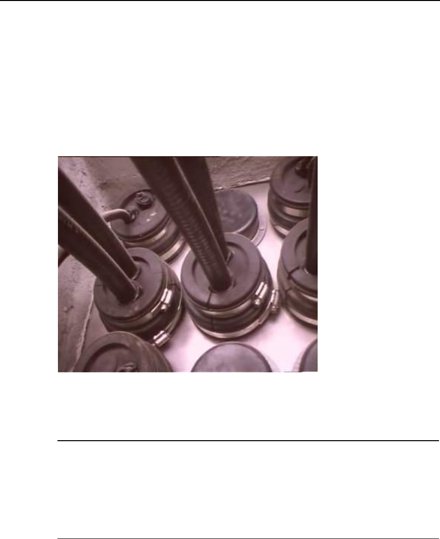
l The antenna should be installed at the place where there is special lightning
arrester or similar facilities such as telecommunication tower around. And the
antenna should be located within the valid protection range of the lightning
arrester. That is, the included angle between the erect direction and the direction
from the antenna RX connector to the lightning arrester or to the tower-top should
be less than 30°. If there is no tower or lightning arrester around, the special
lightning arrester should be installed to meet the design requirements for lightning
protection of the building. The horizontal distance from the lightning arrester to the
antenna should be 2m to 3m preferably. And the lightning arrester should be 0.5m
higher than that of GPS antenna receive connector.
Installation Manual
iSiteC BTS3601C CDMA Base Station Hardware Installation
4 Installing Satellite Synchronization Antenna and Feeder System
4-3
4.2.2 Installing GPS Antenna Support
In terms of varied installations, there are different supports available.
I. On tower
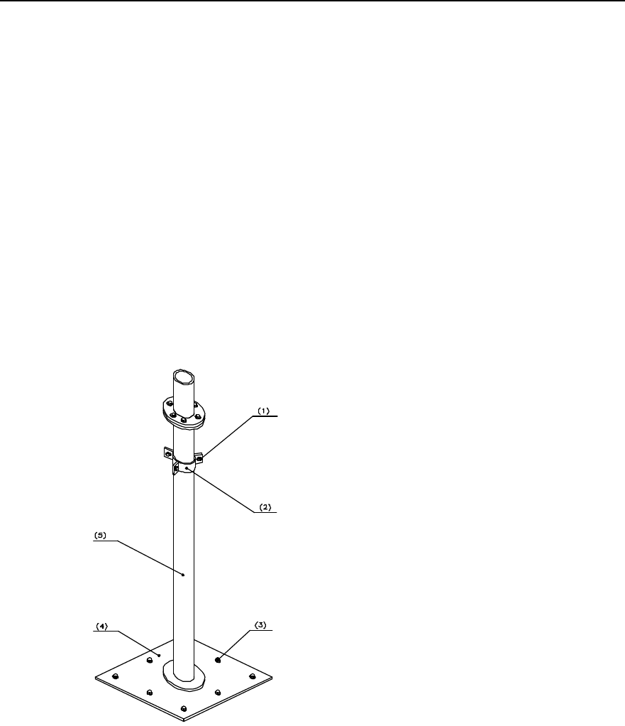
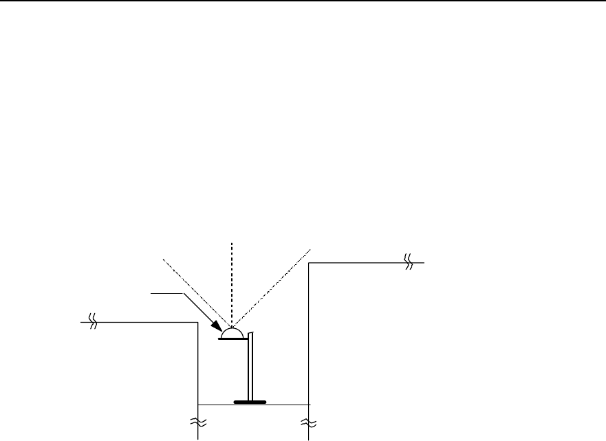
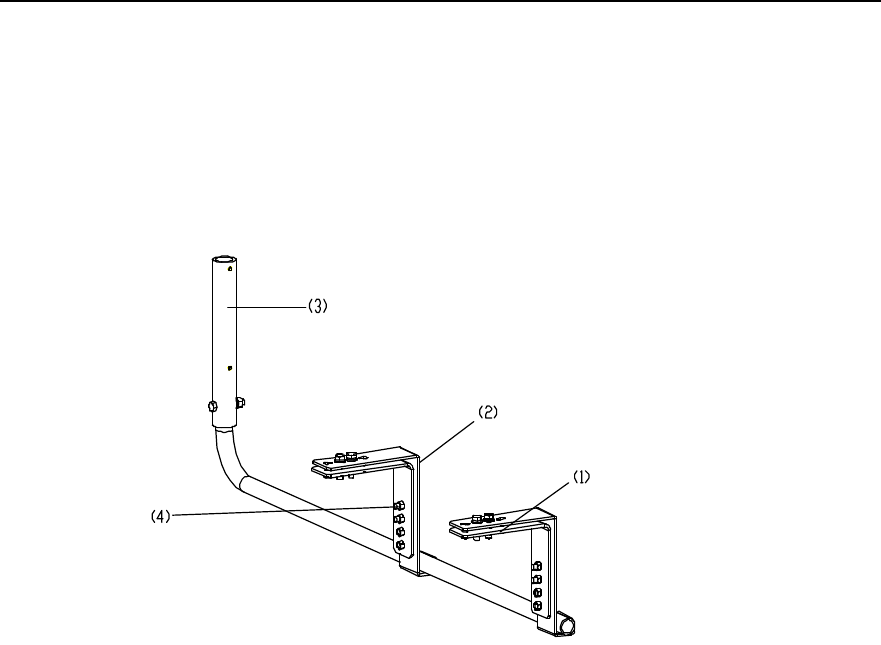
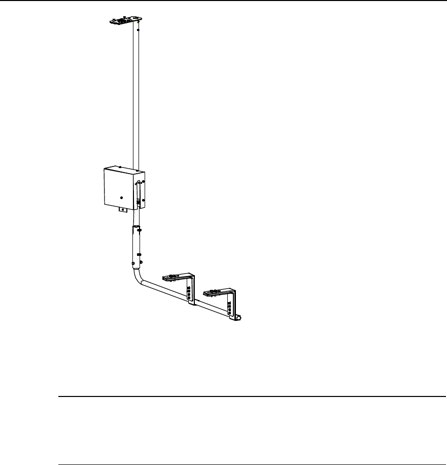
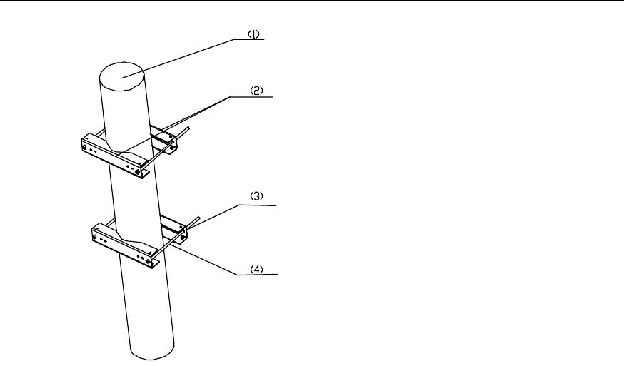
Figure 4-2 illustrates the support installed on tower.
(1) Adjustable clamp (2) Fixed clamp (3) Support (4) M8 bolt
Figure 4-2 Antenna support on tower
Installation procedure is as follows:
1) Unscrew the bolts on the fixed clamps and remove the adjustable clamps;
2) Place the antenna support in the right position on the tower so that the tower angle
steel is between the fixed clamp and the adjustable clamp;
3) Fix the support on the tower with fasteners including bolts, plain washers, spring
washers and nuts;
4) Insert the antenna support lever into the support and put it through the bolt holes.
Tighten the bolts to fix the antenna support.
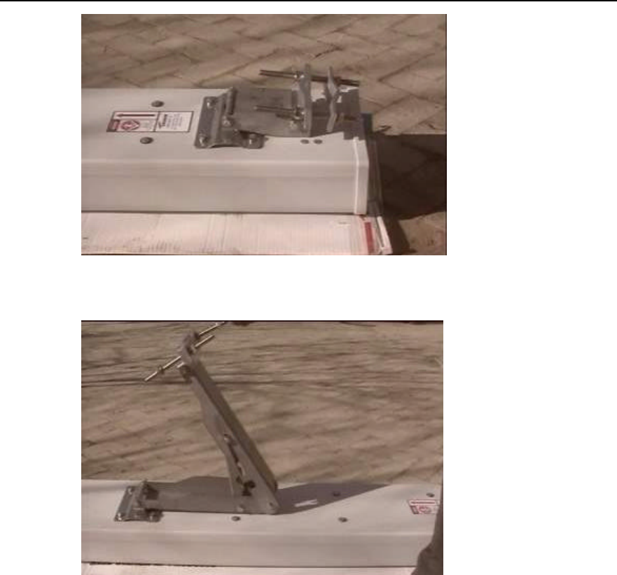
Figure 4-3 illustrates an installed antenna support on tower.
Installation Manual
iSiteC BTS3601C CDMA Base Station Hardware Installation
4 Installing Satellite Synchronization Antenna and Feeder System
4-4
Figure 4-3 Installed antenna support on tower
&
Note:
For the tower without angle steel, the above mentioned antenna support cannot be used. Antenna support
for metal mast can be adopted. Please refer to the section right below for its installation.
II. On metal mast
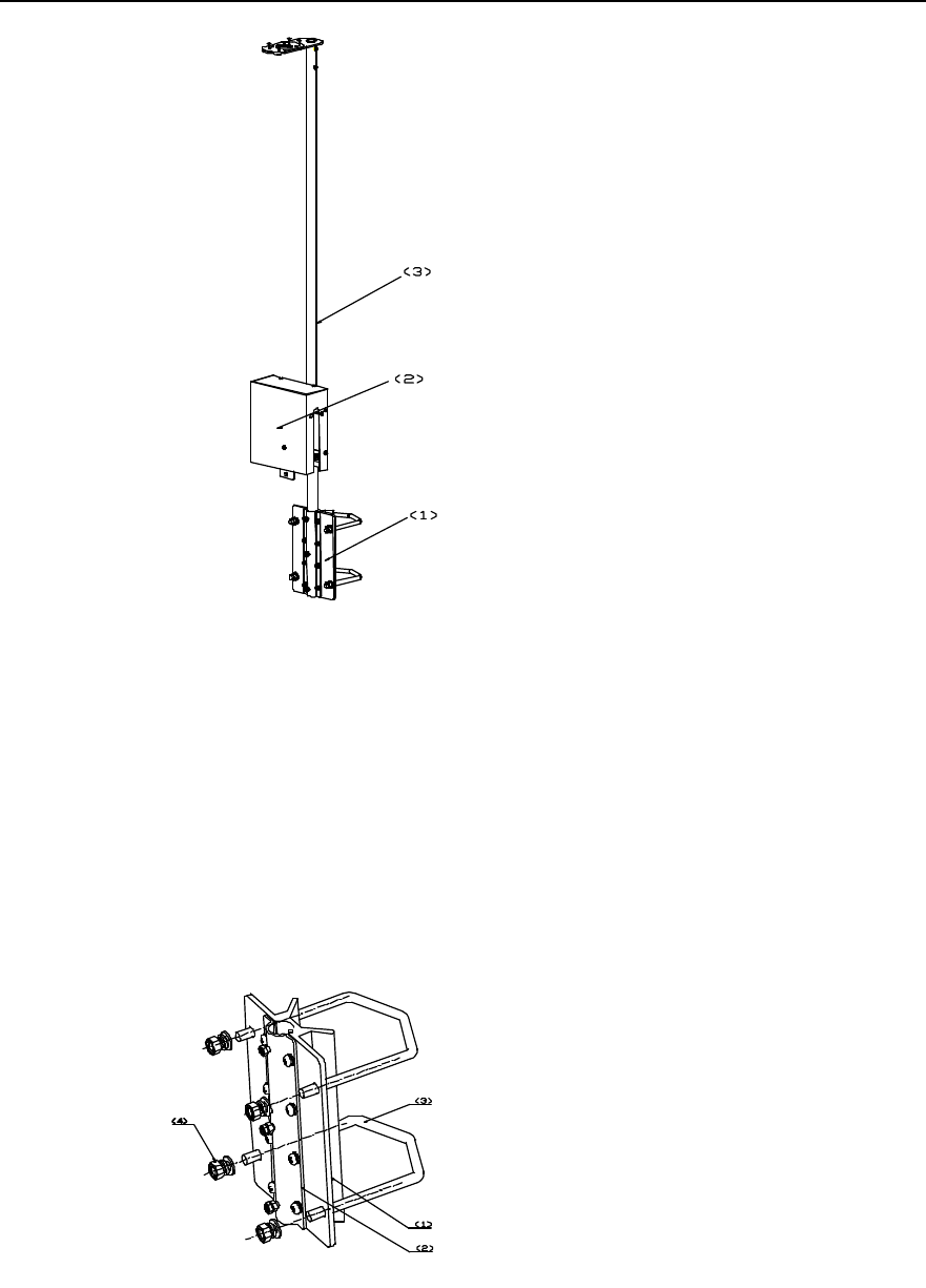
The antenna support for installation on metal mast is shown in Figure 4-4.
Installation Manual
iSiteC BTS3601C CDMA Base Station Hardware Installation
4 Installing Satellite Synchronization Antenna and Feeder System
4-5
(1) GPS installation anchor ear (2) Lightning arrester encloser (3) Support
Figure 4-4 Antenna support for installation on metal mast
Installation procedure is as follows:
1) Unscrew the fastening bolts on GPS installation anchor ear and remove the
anchor ear.
2) Round the U-shape clip on the metal mast for GPS antenna. Fasten M10 bolt to fix
the GPS installation anchor ear on the metal mast. The structure of GPS
installation anchor ear is shown in Figure 4-5.
(1) Front clamp (2) Rear clamp (3) U-shape clip (4) M10 bolt
Figure 4-5 Structure of GPS installation anchor bolt
Installation Manual
iSiteC BTS3601C CDMA Base Station Hardware Installation
4 Installing Satellite Synchronization Antenna and Feeder System
4-6
3) Remove the rear clamp on the GPS installation anchor ear. Put the antenna
support lever between the front clamp and the rear clamp. Then adjust the
direction of the antenna support lever.
4) Fasten the rear clamp and the bolts to secure the antenna support lever.
III. On building-top
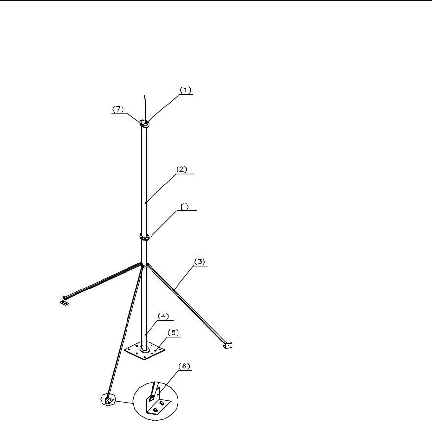
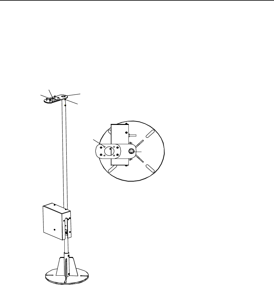
The GPS antenna support for installation on building-top is shown in Figure 4-6.
M1
M2(4 screws)
M3
B1(2 bolts)
M2
M1
M3
Figure 4-6 Structure of GPS antenna support on building-top
Install procedure is as follows:
1) Place the metal base of the antenna support on the concrete base and align the
centers. Mark the position of the installation holes with an engineering pen.
2) Drill holes at the marks using a drill with the bit of v12.
3) Install expansion bolts to secure the base. In order to keep the antenna pole erect
so as to reach better receiving performance, try to keep the metal base level using
washers.
4) Insert the support lever into the base to see whether the lever is erect. It is required
that the included angle between the support lever and the direction of the plummet
be smaller than 5°. If the requirement can not be satisfied, adjust the base.
Installation Manual
iSiteC BTS3601C CDMA Base Station Hardware Installation
4 Installing Satellite Synchronization Antenna and Feeder System
4-7
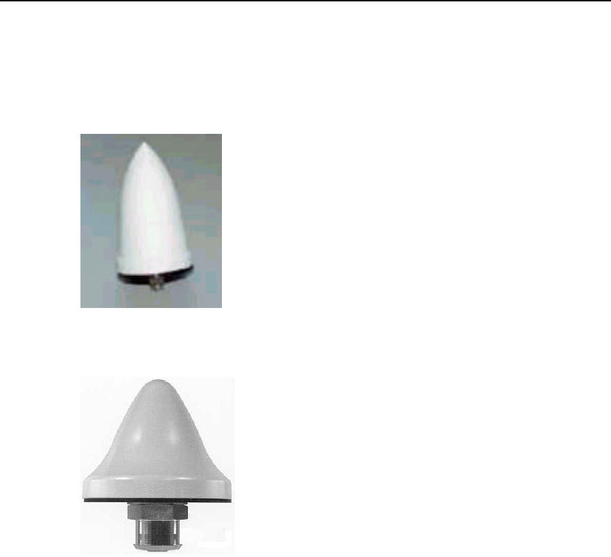
4.2.3 Installing Antenna
There are various types of antennae. Figure 4-7 and Figure 4-8 show two types of
common antennae. The following gives the installation of two types of GPS antennae
respectively.
Figure 4-7 GPS antenna of type AT1670-0
Figure 4-8 GPS antenna of type UTONCORE
I. Installing GPS antenna of type AT1670-0
1) Insert the jumper connector at the antenna bottom into M3 of the antenna support
as shown in Figure 4-6;
2) Fasten the four accessory UK-standard bolts at M2;
3) Tighten the antenna and the cable connector.
II. Installing GPS antenna of type UTONCORE
1) UTONCORE GPS antenna has such auxiliary fixtures as a rubber washer, a metal
plain washer and a bolt. During installation, first unfix the bolt at the antenna
bottom and install the rubber washer instead. Then insert the antenna into M3 of
the antenna support as shown in Figure 4-6;
2) Install the metal plain washer on the jumper connector at the bottom of the
antenna (with the washer head tightly against the bottom of M3);
Installation Manual
iSiteC BTS3601C CDMA Base Station Hardware Installation
4 Installing Satellite Synchronization Antenna and Feeder System
4-8
3) Tighten the antenna connector and the cable socket. Finally reinstall the unfixed
bolt. Thus the GPS antenna is fixed on the ellipse holder of the antenna support.
Caution:
1) Waterproof treatment should be performed at the antenna connector. Please refer to Section 2.3.6 for
waterproof treatment process.
2) Upon completion of installation, cover the antenna support with anti-rust paint, especially the fastening
bolts, expansion bolts and the places around the bolt holes.
4.3 Installing GPS Feeder
GPS feeder installation includes the installation of jumpers, antenna-side lightning
arrester, feeder, equipment-side lightning arrester, etc. The intallation and routing of
GPS feeder is similar to that of RF feeder. Following gives explanation of points for
attention and grounding requirements during the installation.
4.3.1 Routing Feeder
Prior to feeder routing, carefully check the routing environment including the tower and
building-top. Determine the routing scheme and sequence as per the engineering
drawing.
l In the case of BTS indoor installation, the route leading the feeder from the
installation position to the equipment room containing the cabinet and equipment
should be clear. It should facilitate fixing the cable properly and meet the routing
requirements in the equipment room. In addition, reliable measures should be
taken to protect the feeder from rain and corrosion.
l 1.5m jumper should be bound at the outside of the antenna support lever evenly
with cable ties. In addition all cable ties should be fastened, with the same spacing
of 200mm. The cable tie heads should be toward the same direction, and all the
ties should be cut neatly to the end.
l Waterproof elbow should be made at the entrance where the feeder enters the
equipment room. The vertical distance from the lowest point of the waterproof
elbow to the entrance should not be less than 200mm so as to prevent rain from
entering the room.
l In the case of GPS antenna installed on building-top, connectors at both ends of
the feeder should be protected with strong materials (such as packing bags for
board) to prevent damage to the connectors. The feeder should be fixed with
plastic clips attached with steel nails along the root of the parapet on the
Installation Manual
iSiteC BTS3601C CDMA Base Station Hardware Installation
4 Installing Satellite Synchronization Antenna and Feeder System
4-9
building-top. The spacing between plastic clips should be 1m. And the direction of
the clip heads should be interlaced regularly. If two feeders are joined, they should
be bound together without intersection or curve.
l When routing the feeder, try to expand the feeder roll before routing. Try to avoid
bending of it. If it is unavoidable to bend the feeder, the bent radius should not be
less than the minimum of the allowed bent radius for the cables so as to avoid
damage to the feeder.
Caution:
When the distance from the antenna to the BTS is greater than 100m, 7/8 feeder should be adopted so as
to minimize signal loss. If it is unavailable, 1/2 feeder should be adopted, instead.
4.3.2 Installing Lightning Arrester
There are two types of lightning arresters for GPS antenna, i.e. antenna-side lightning
arrester and equipment-side lightning arrester. The former is used for lightning
protection for active GPS antennae, while the latter for the GPS card. The two arresters
are of the same model.
Currently there are two types of lightning arresters. The installation procedure for each
type is described in detail as follows:
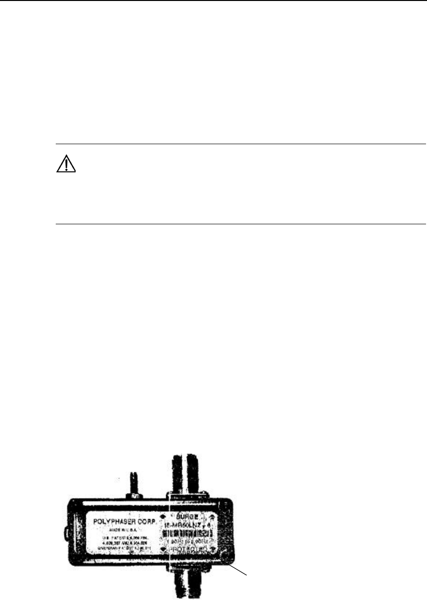
I. Type iS-MR50LNZ+6 lightning arrester
Figure 4-9 illustrates the appearance of Type iS-MR50LNZ+6 lightning arresters.
(1)
(1) PROTECTED end
Figure 4-9 Appearance of Type iS-MR50LNZ+6 lightning arrester
Installation Manual
iSiteC BTS3601C CDMA Base Station Hardware Installation
4 Installing Satellite Synchronization Antenna and Feeder System
4-10
Attention:
1) GPS antenna-side lightning arrester
l The "PROTECTED" end of the GPS lightning arrester should face the antenna.
That is, the "PROTECTED" end of the arrester is connected with the jumper end.
l The lightning arrester should not be grounded when it is installed either on the
tower or on building-top, but the feeder grounding clip should be as close as
possible to the lightning arrester.
l The lightning arrester is installed inside the lightning arrester box, with its
connectors sealed with waterproof adhesive tape and PVC tape in sequence, so
as to prevent moisture invasion.
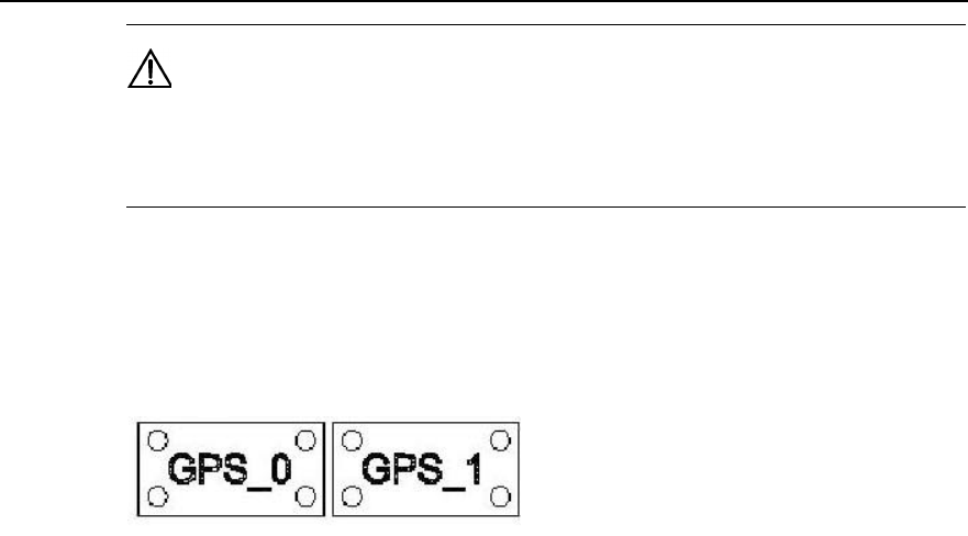
2) GPS equipment-side lightning arrester
l The "PROTECTED" end of GPS lightning arrester should face the BTS. That is,
the "PROTECTED" end of the arrester is connected with the GPS port of the BTS.
l In the case of BTS indoor installation, dual-male conversion connector should be
used to connect the lightning arrester directly to the GPS port of MBPM. It is
unnecessary to connect the lightning arrester to lightning protection grounding
cable.
l In the case of BTS outdoor installation, dual-male-connector jumper of 0.3m long
should be used to connect the lightning arrester to the GPS port of MBPM. The
arrester should then be connected to the lightning protection grounding cable that
leads to the grounding bar of the BTS. The connector between the arrester and the
feeder should be sealed with waterproof adhesive tape and PVC tape in sequence,
so as to prevent moisture invasion.
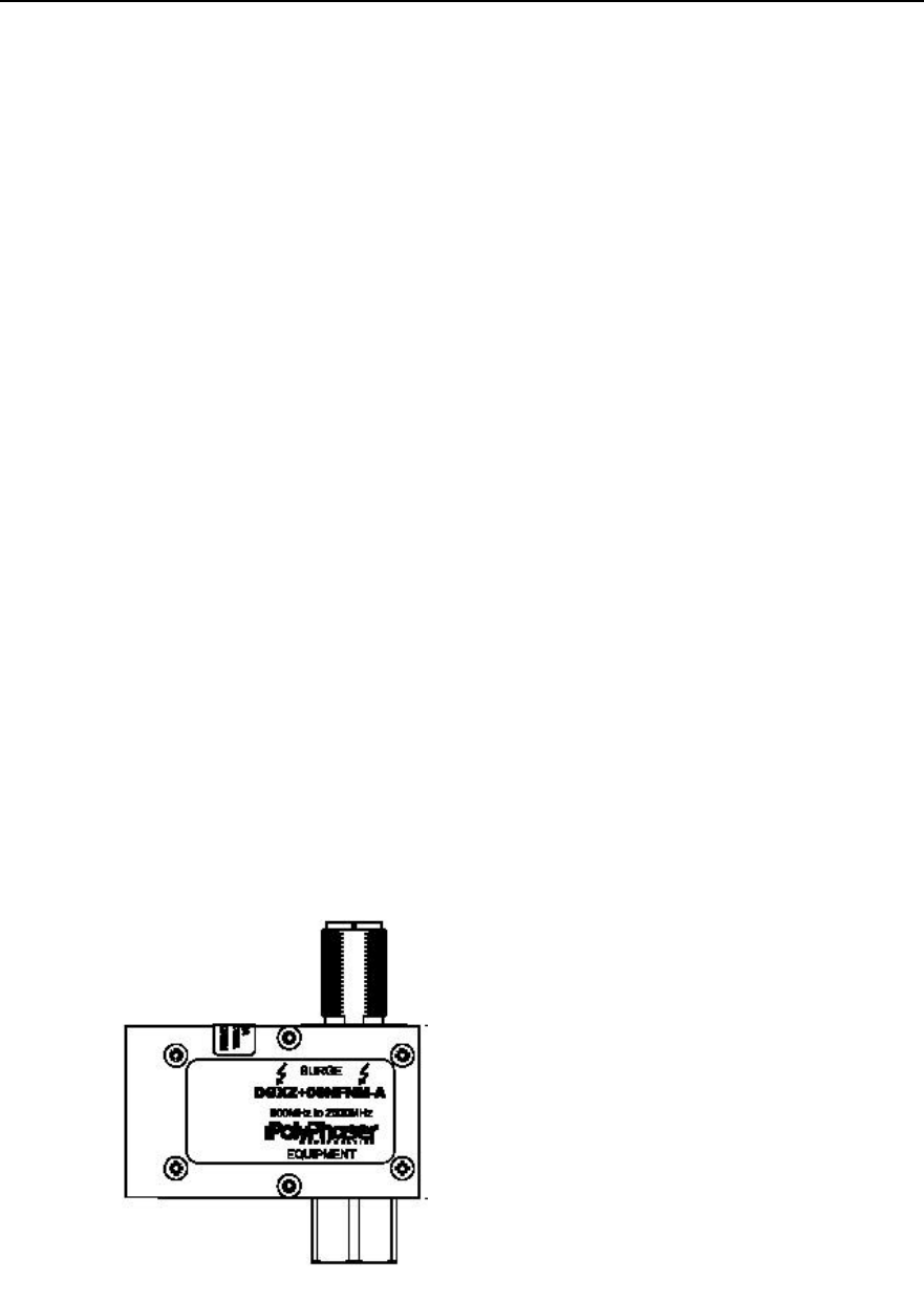
II. Type DGXZ+6NFNM-A lightning arrester
Figure 4-10 illustrates the appearance of Type DGXZ+6NFNM-A lightning arrester.
Figure 4-10 Appearance of Type DGXZ+6NFNM-A lightning arrester
Attention:
Installation Manual
iSiteC BTS3601C CDMA Base Station Hardware Installation
4 Installing Satellite Synchronization Antenna and Feeder System
4-11
1) GPS antenna-side lightning arrester
l The connectors on both ends of Type DGXZ+6NFNM-A lightning arrester are
male and female respectively. Therefore, jumpers with male and female
connectors should be prepared for the installation of the lightning arrester. The
male connector of the jumper is connected with the GPS antenna, while the
female connector on the other end is connected with the male connector of the
lightning arrester.
l The lightning arrester should not be grounded when it is installed either on the
tower or on building-top, but the feeder grounding clip should be as close as
possible to the lightning arrester.
l The lightning arrester is installed inside the lightning arrester box, with its
connectors sealed with waterproof adhesive tape and PVC tape in sequence, so
as to prevent moisture invasion.
2) GPS equipment-side lightning arrester
l In the case of BTS indoor installation, the lightning arrester may be directly
connected to the GPS port of MBPM. And it is unnecessary to connect the
lightning arrester to the lightning protection grounding cable.
l In the case of BTS outdoor installation, a 0.3m jumper with both male and female
connectors should be used. Its male connector is connected to the GPS port of
MBPM of the BTS, while its female connector to the male connector of the
lightning arrester. The lightning arrester should be connected to the lightning
protection grounding cable that leads to the grounding body of the BTS. And the
connector between the lightning arrester and the feeder should be sealed with
waterproof adhesive tape and PVC tape in sequence, so as to prevent moisture
invasion.
4.3.3 Grounding Requirement
GPS feeder grounding and routing are conducted simultaneously. The following gives
description of feeder grounding points in different installations.
I. BTS outdoor installation (building-top installation excluded)
l Within the range of 1m~2m under the GPS antenna;
l The front end connecting the BTS.
Caution:
If the GPS feeder is not longer than 5m, its shielding covering may be grounded only at the front end
connecting the BTS.
Installation Manual
iSiteC BTS3601C CDMA Base Station Hardware Installation
4 Installing Satellite Synchronization Antenna and Feeder System
4-12
II. BTS outdoor installation on building-top
In this installation mode, GPS feeder shielding covering may be grounded only at the
front end connecting the BTS.
III. BTS indoor installation with GPS antenna and BTS antenna installed on the
same tower or metal mast
1) When the outdoor GPS feeder is longer than 20m:
l Within the range of 1m~2m under the GPS antenna;
l Within 1m range of the mast or of where the GPS feeder is led from the tower
platform;
l At the outer side of the feeder window where the GPS feeder enters the equipment
room (connecting to outdoor protection grounding bar).
l Close to the indoor protection grounding bar after it enters the equipment room.
2) When the outdoor GPS feeder is not longer than 20m:
l Within the range of 1m~2m under the GPS antenna;
l At the outer side of the feeder window where the GPS feeder enters the equipment
room (connecting to outdoor protection grounding bar).
l Close to the indoor protection grounding bar after it enters the equipment room.
Caution:
1) If the GPS feeder is longer than 60m, feeder grounding clips should be applied in the middle of the
feeder, with the clip spacing of 20m.
2) If the GPS feeder is led into the room after being routed for a stretch of distance on the building-top, and
the distance exceeds 20m, a feeder grounding clip is required on the top of the building.
3) For the GPS feeder that enters the room from the building-top along the wall, if a cabling rack is used,
the cabling rack should also be grounded.
IV. BTS indoor installation with GPS antenna not on the BTS tower but
separately placed
l The shielding covering of GPS feeder is grounded at the entrance to the building.
The grounding point should be the outdoor grounding bar of the mobile equipment
room. The grounding cable should adopt the plastic insulation copper core wire of
diameter not less than 6mm2. It should be black, or yellow and green.
l If the feeder is longer than 60m, feeder grounding clips should be applied in the
middle of the feeder, with the clip spacing of 20m.
l Place the GPS feeder close to the indoor protection grounding bar after it enters
the equipment room.
Installation Manual
iSiteC BTS3601C CDMA Base Station Hardware Installation
4 Installing Satellite Synchronization Antenna and Feeder System
4-13
Caution:
When the GPS feeder is not longer than 10m, the shielding covering of the coaxial feeder may be
grounded at one point indoor only.
4.3.4 Feeder Label
Figure 4-11 illustrates the standard nameplate used as GPS feeder label.
Figure 4-11 GPS feeder label
I. BTS indoor installation
GPS feeder labels can be affixed in three positions:
l 0.3m to the outdoor feeder connector;
l Outside the feeder entrance to the feeder window;
l 0.3m to the indoor feeder connection.
II. BTS outdoor installation
GPS feeder labels can be affixed in two positions:
l 0.3m to the outdoor feeder connector;
l 0.3m to the front end connecting the BTS.

Installation Manual
iSiteC BTS3601C CDMA Base Station Table of Contents
i
Table of Contents
5 Installation Check ..............................................................................................................5-1
5.1 Overall Check............................................................................................................5-1
5.1.1 Checking Equipment Installation .......................................................................5-1
5.1.2 Checking Cable Connection..............................................................................5-1
5.1.3 Checking Lightning Protection Grounding ..........................................................5-1
5.2 Power-on Check........................................................................................................5-3
5.3 Checking Environment Condition ................................................................................5-3
5.4 System Commissioning..............................................................................................5-3

Installation Manual
iSiteC BTS3601C CDMA Base Station Hardware Installation
错误 未找到引用源 错误 未找到引用源
5-1
5 Installation Check
Upon completion of all hardware installation, check the installation including the
following aspects: overall check, power-on check, environment condition check and
system commissioning.
5.1 Overall Check
5.1.1 Checking Equipment Installation
l All the equipment should be steady and neat in appearance when installed.
l All the bolts and nuts are fastened. And plain washers and spring washers are
applied under all the nuts with the plain washer under the spring washer.
l There should be no missing or damaged parts on the equipment, and all the
cables should be intact.
l The rack interior should be cleaned. Fingerprints and smudges left during the
installation should be cleaned. There should be no dust in the rack.
5.1.2 Checking Cable Connection
l Power cables should be well connected. The connector should not be loose or
damaged. And there should be no scratch or fissure on the power cable skin.
l Check whether the contact of the grounding cable is good.
l Check whether the trunk cable connections are secure and correct.
l All the cables should be secure. Do not over-strain the cables running round the
corner. Cables and fibers should run in straight and smooth courses without any
cross. Cables and fibers in the same direction should be bundled up. The cable
layout should be neat and tidy with the same bundling space. Signal cables cannot
be bundled with power cables and grounding cables.
l There should be no damage to the skin of all the cables.
5.1.3 Checking Lightning Protection Grounding
I. Checking outdoor grounding
Outdoor grounding check includes the following aspects:
l Outdoor grounding bar should be connected to the counterpoise with grounding
bus. DO NOT connect the outdoor grounding bus to the grounding flat steel of the
feeder lightning arrester.

Installation Manual
iSiteC BTS3601C CDMA Base Station Hardware Installation
错误 未找到引用源 错误 未找到引用源
5-2
l Check whether there is good electrical connection between the UPS shell and the
UPS external box via screws. UPS external box should be grounded.
l Check whether the protection grounding cable of AC lightning protection box or
IAFB is directly connected to the protection grounding bar. Make sure the
grounding cable is shorter than 1m.
l The AC power cable from the exterior to the BTS should be directly connected to
the AC lightning protection box (when AC lightning protection box is available) or
to the IAFB (when AC lightning protection box is unavailable). It is not allowed to
connect the external power cable to the power distribution terminal in the work box
first and then to the AC lightning protection box.
l When E1 cable is used for signal transmission of the BTS, if the E1 cable from the
exterior to the BTS is coaxial cable with metal shell (provided by the user), its
metal shell should be grounded with grounding clip. The grounding cable from the
grounding clip should be directly connected to the protection grounding bar
instead of to the grounding bar of the IAFB.
l In BTS outdoor tower installation mode, the shielding covering of the BTS coaxial
feeder should be grounded at the tower-top and the front end connecting the BTS.
The grounding cable should be connected to the tower body nearby. The
protection grounding bar should have separate grounding donwlead that is not
insulated from the tower body.
l When the feeder is not shorter than 60m, the shielding covering of the coaxial
feeder should be grounded at the middle of the tower body.
II. Checking indoor grounding
Indoor grounding check includes the following aspects:
l In BTS indoor installation, there should be indoor grounding bar and outdoor
grounding bar that should be led into the counterpoise separately instead of being
connected in series directly with grounding cables.
l The grounding cable at the point where the feeder enters the feeder window is
connected to the outdoor grounding bar in the direction from the antenna to the
BTS.
l The AC lightning protection box provides separate grounding cable to connect to
the indoor grounding bar. The grounding cable from the AC lightning protection
box or from the IAFB to the indoor grounding bar should be shorter than 1m.
l Check whether there is good electrical connection between the UPS shell and the
UPS external box via screws. UPS external box should be grounded.
l When E1 cable is used for signal transmission of the BTS, if the E1 cable from the
exterior to the BTS is coaxial cable with metal shell (provided by the user), its
metal shell should be grounded with grounding clip. The grounding cable from the
grounding clip should be directly connected to the indoor grounding bar instead of
to the grounding bar of the IAFB.

Installation Manual
iSiteC BTS3601C CDMA Base Station Hardware Installation
错误 未找到引用源 错误 未找到引用源
5-3
l The shielding covering of the coaxial feeder should be well grounded at the
tower-top, tower-bottom and the outside of the entrance to the equipment room.
When the feeder is not shorter than 60m, the shielding covering of the coaxial
feeder should be grounded at the middle of the tower body.
l The outdoor grounding bar and indoor protection grounding bar should share the
counterpoise of the equipment room. The outdoor grounding bar should not be
connected to the tower counterpoise for grounding.
l The feeder skin should be grounded after the feeder enters the equipment room.
The grounding cable from the feeder skin should be directly connected to the
indoor grounding bar.
5.2 Power-on Check
1) Check whether the voltage of the power supply is normal (normal voltage range:
150VAC~300VAC). If it is normal, turn on the power switch of the BTS and check
whether the indicators on the power supply module of the BTS are normal. Please
refer to User Manual for indicator descriptions.
2) Observe the running of boards and modules. Cut off the power supply immediately
in case of any exception. Power on all the boards and modules after the fault is
removed.
5.3 Checking Environment Condition
1) There should be no sundries inside or on top of the sun-shading cover. The cover
should be clean without any smudge or fingerprint.
2) There should be no redundant tape or cable tie on the cable.
3) There should be no tape, cable tie head, waste paper, or packing bag around the
BTS.
4) All the things around the BTS should be clean and neat in their original
appearance.
5.4 System Commissioning
After the BTS is powered on, if the indicators of all the modules are normal, system
commissioning should be performed by starting some basic operations and
maintenance and function test. The following briefs the items of system commissioning:
1) Location update flow
2) MO call flow
3) MT call flow
4) Handover flow
5) MO SM flow
6) MT SM flow
7) MO packet data flow
Installation Manual
iSiteC BTS3601C CDMA Base Station Hardware Installation
错误 未找到引用源 错误 未找到引用源
5-4
8) MS packet data flow test (downlink traffic rate).
&
Note:
System commissioning items can be determined as per the specific situation at the site. The above is the
system commissioning item list. For details, please refer to relevant engineering documents.

Installation Manual
iSiteC BTS3601C CDMA Base Station Table of Contents
i
Table of Contents
A Installing IAFB.................................................................................................................. A-1
A.1 Installation Flow ....................................................................................................... A-1
A.2 Wall Installation ........................................................................................................ A-1
A.3 Metal Mast Installation .............................................................................................. A-4
A.4 Pole Installation........................................................................................................ A-5
A.5 Installation Check..................................................................................................... A-6
B Requirements for Antenna Isolation ................................................................................B-1
C Making Connectors..........................................................................................................C-1
C.1 Overview.................................................................................................................C-1
C.2 Making 7/16 DIN Connector and N Connector for Jumper ...........................................C-1
C.3 Making 7/16 DIN Connector and N Connector for 7/8 Feeder ......................................C-5
D Preparing Grounding Clips ..............................................................................................D-1
D.1 Overview.................................................................................................................D-1
D.2 Preparation Process.................................................................................................D-1
Installation Manual
iSiteC BTS3601C CDMA Base Station Hardware Installation
A Installing IAFB
A-1
A Installing IAFB
There are 3 installation modes for IAFB: Wall installation, metal mast installation
(v60~v114) and pole installation (v150~v350).
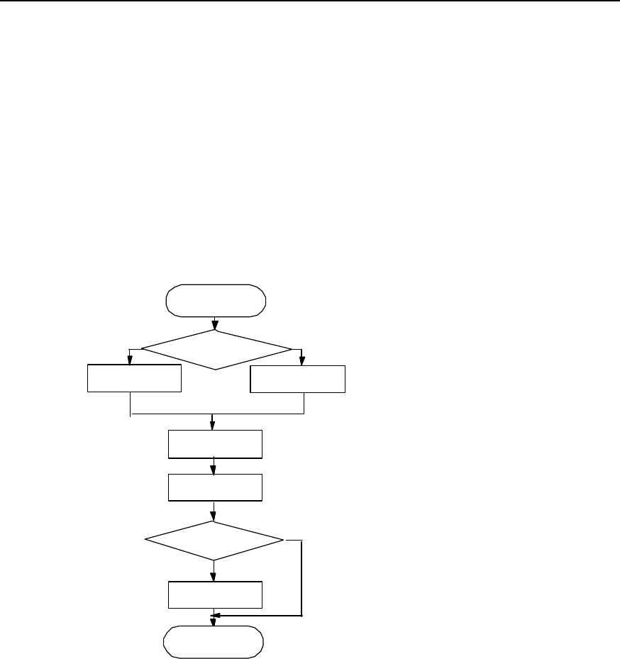
A.1 Installation Flow
Figure A-1 is the installation flow of IAFB.
Install IAFB
Install sun-shading
cover
Wall installation Metal mast or pole
installation
Install
fastener
Fit bolt
Install hanger
Outdoor
installation?
Y
N
Select installation
mode
Start
End
Figure A-1 IAFB installation flow
A.2 Wall Installation
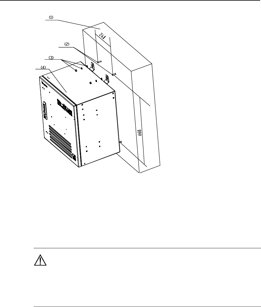
The wall installation procedure of IAFB is as follows:
1) Determine a proper installation position on the wall. Mark it with a pencil as the
hole for bolt. The hole is the key position for bracket installation, as shown in
Figure A-2.
Installation Manual
iSiteC BTS3601C CDMA Base Station Hardware Installation
A Installing IAFB
A-2
(1) Wall (2) M8%80 exploded expansion bolt (3) Bolt, plain washer, spring washer (4) Box
Figure A-2 Fixing bolts
2) Drill a hole with the drill bit of v10mm at the mark for the bolts, Then mount the
exploded expansion M8%80 bolt.
Caution:
The depth of the hole is 50mm~60mm. It cannot be too deep; otherwise, the installation may be affected by
the part of the expansion bolt extended outside the wall. Neither can it be too shallow, otherwise it may
affect the reliability of the BTS.
3) Determine the other three holes with a plumb line and a ruler and mark them with a
pencil.
4) The procedure to drill holes and install the expansion bolts is similar to that
mentioned above.
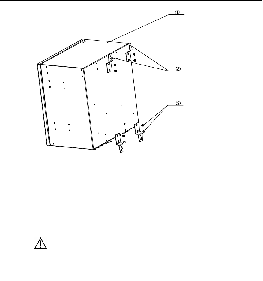
5) Use combination screw M6%12 to mount the 4 hangers on the back of the box, as
shown in Figure A-3.
Installation Manual
iSiteC BTS3601C CDMA Base Station Hardware Installation
A Installing IAFB
A-3
(1) Box (2) Hanger (3) M6%12 bolt
Figure A-3 Installing hanger
6) Mount the hangers of IAFB aiming at the four bolts. Mount plain washer, spring
washer and nut on the bolt. Then fasten the nut clockwise with an adjustable
wrench to fix the bracket on the wall.
Caution:
The length of the bolt outside the wall should be about 20mm. And the washer should be mounted before
the nut is fastened.
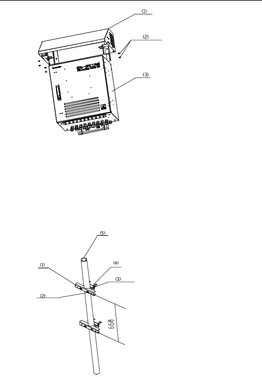
7) The installation of sun-shading cover is shown in Figure A-4. It is fixed with
M12%16 bolt.
Installation Manual
iSiteC BTS3601C CDMA Base Station Hardware Installation
A Installing IAFB
A-4
(1) Sun-shading cover (2) M12%16 bolt (3) Box
Figure A-4 Installing sun-shading cover
A.3 Metal Mast Installation
The installation procedure of IAFB metal mast is as follows:
1) Mount the beam and fastener to the steel pipe with M10 bolt and nut. The pipe is
between the beam and the fastener. Then fasten the bolt and nut. See Figure A-5.
(1) Beam (2) M10 bolt (3) Plain washer, spring washer, nut (4) Fastener (5) Steel pipe
Figure A-5 Installing beam and fastener
Installation Manual
iSiteC BTS3601C CDMA Base Station Hardware Installation
A Installing IAFB
A-5
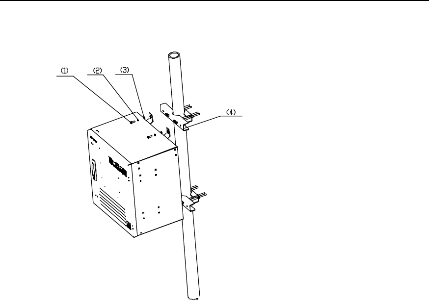
2) Lean the box of IAFB on the beam and let M8%25 bolt go through the hanger of
IAFB. Then fasten the IAFB to the beam. See Figure A-6.
(1) M8%25 bolt (2) Spring washer (3) Plain washer (4) Beam
Figure A-6 Fixing IAFB
A.4 Pole Installation
The installation procedure of IAFB pole is as follows:
1) Lean the fastener to the pole and fasten the beam to let the pole be in the middle of
the pole. Then fasten the beam with bolt and nut. Refer to Figure A-7 below.
Installation Manual
iSiteC BTS3601C CDMA Base Station Hardware Installation
A Installing IAFB
A-6
(1) Pole (2) Fastener (3) Plain washer, spring washer, nut (4) M12 bolt
Figure A-7 Fixing fastener
2) Fix the IAFB to the fastener with M8%25 bolt. Its installation procedure is similar to
that on metal mast. See Figure A-6.
A.5 Installation Check
After all the parts are installed, check the installation in the following aspects: parts
installation overal check, BTS power-on check and environment check.
I. Overall Check
As a review on the whole foregoing installation process, the overall check includes the
following items:
1) Fixation check
The IAFB installed should satisfy the following requirements:
l The IAFB should be secure with neat appearance.
l All the bolts and nuts are fastened with plain washer and spring washer mounted
in correct sequence.
l There should be no missing or damaged parts, and all the cables should be intact.
l The IAFB should be clean without any smudge, fingerprint or dust.
2) Cable connection check
l Power cables should be well connected. The plugs should not be loose or
damaged. And there should be no scratch or fissure on the power cable shell.
l Check whether the contact of the grounding cables is good.

Installation Manual
iSiteC BTS3601C CDMA Base Station Hardware Installation
A Installing IAFB
A-7
l All the cables should be secure. Do not over-strain the cables running round the
corner. Cables and fibers should run in straight and smooth courses without any
cross. Cables and fibers in the same direction should be bundled up. The cable
layout should be neat and tidy with the same bundling space.
l There should be no damage to the shell of all the cables.
II. Environment condition check
1) There should be no sundries inside or on top of the sun-shading cover. The cover
should be clean without any smudge or fingerprint.
2) There should be no redundant tape or cable tie on the cable.
3) There should be no tape, cable tie head, waste paper, or packing bag around the
IAFB.
4) All the things around the BTS should be clean and neat in their original
appearance.
III. Power-on check
Open the door of the IAFB and check whether the voltage of the power supply is normal.
If ther power switch is turned on normally, test with the multimeter whether the output
voltage is normal.

Installation Manual
iSiteC BTS3601C CDMA Base Station Hardware Installation
B Requirements for Antenna Isolation
B-1
B Requirements for Antenna Isolation
I. Requirements for isolation of omni antenna
Based on the conditions that antenna gain is 10dBi and isolation is 30dB, the spacing
between antennae is required as follows:
l When antennae are installed horizontally, the horizontal spacing between transmit
(TX) antenna and receive (RX) antenna should not be less than 5.3m.
l When antennae are installed vertically, the vertical spacing between TX antenna
and RX antenna should not be less than 0.2m.
l According to the requirements for diversity receiving of omni RX antenna, the
horizontal spacing between RX antennae should not be less than 4m.
II. Requirements for isolation of directional antenna
1) Single polarization antenna
Based on the conditions that antenna gain is 15dBi, isolation is 30dB and half-power
angle is 65°, the spacing between antennae is required as follows:
l When antennae are installed horizontally, the horizontal spacing between TX
antenna and RX antenna in the same sector should not be less than 3m.
l When antennae are installed vertically, the vertical spacing between TX antenna
and RX antenna in the same sector should not be less than 0.2m.
l The horizontal spacing between TX antenna and RX antenna in different sectors
should not be less than 0.2m.
l According to the requirements for diversity receiving of directional RX antenna, the
horizontal spacing between RX antennae should not be less than 4m
2) Dual polarization antenna
For dual polarization antennae, the spacing between the ports of the RX and TX
antennae is 30dB. Therefore, the horizontal spacing may not be considered during
horizontal installation. But in vertical installation, the vertical spacing between antennae
of different sectors should not be less than 0.2m.
&
Note:
The antenna isolation requirements in this section are subject to typical applications. They are for
reference only. During the actual installation, the antenna isolation should be determined by the relevant
engineering design documents.
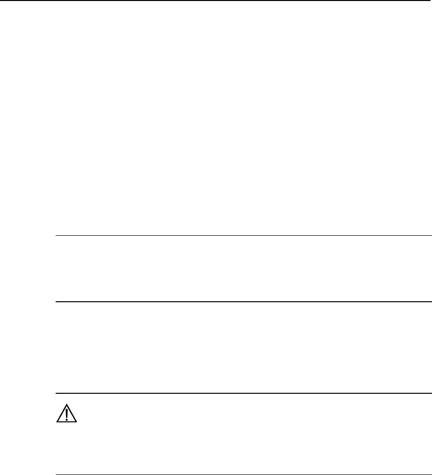
Installation Manual
iSiteC BTS3601C CDMA Base Station Hardware Installation
C Making Connectors
C-1
C Making Connectors
C.1 Overview
Preparation of connectors is a very important job during the installation of antenna and
feeder system. Normative and correct operation will directly affect the performance of
the antenna and feeder system. In this chapter, we respectively introduce the
preparation of the DIN connector and N connector of antenna and feeder for the
reference of project installation.
&
Note:
What described in this section is for reference only. The preparation of connectors for antenna and feeder
should be follow the auxiliary installation instruction for connectors in the actual installation.
C.2 Making 7/16 DIN Connector and N Connector for Jumper
Caution:
The following takes the preparation of 7/16 DIN connector as an example. N connector is prepared in the
same way.
I. Tools required
Spanners (one is 19mm and the other is 22mm), fast cable cutter, fast cable stripper,
safety knife, electric blower, diagonal pliers, nipper pliers, pliers, file, brush and ruler
are all required.
II. Making connectors
1) Get the required tools ready and put them in a convenient place.
2) Cut the jumper to be mounted with a connector to the accurate length.
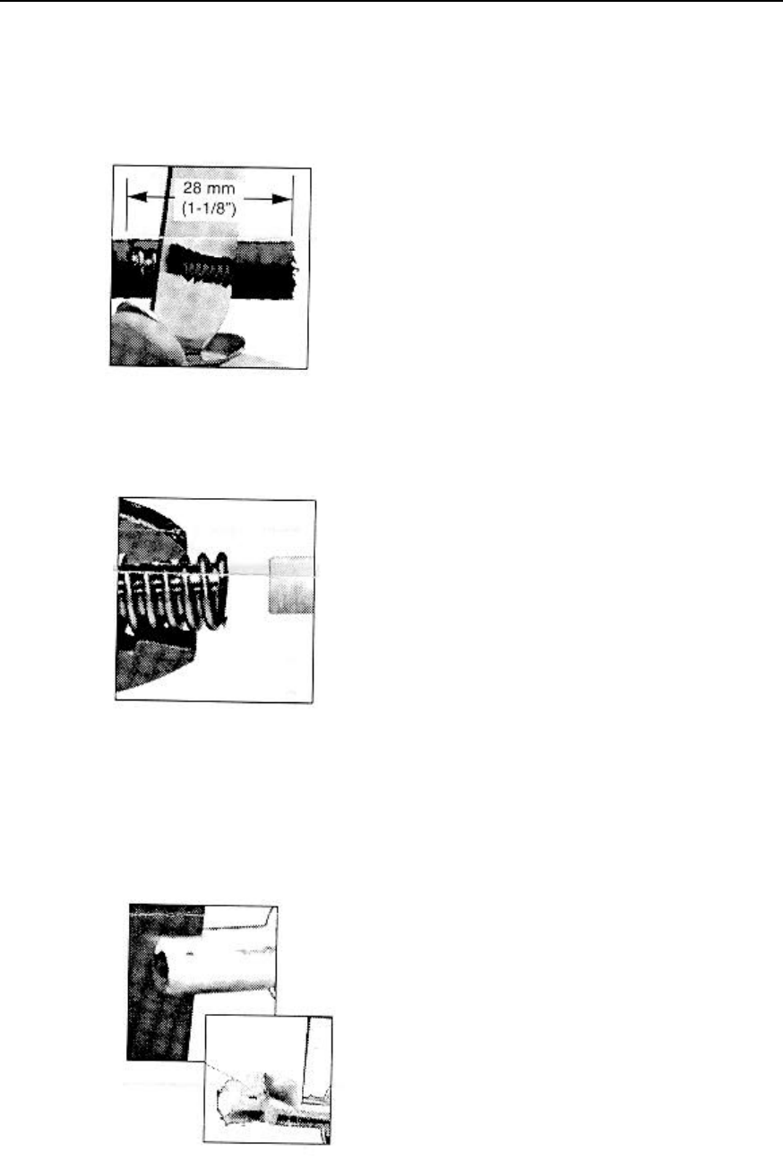
Installation Manual
iSiteC BTS3601C CDMA Base Station Hardware Installation
C Making Connectors
C-2
3) Cut the skin of the cable at 28 mm away from the connector with the fast cable
cutter and the safety knife, as shown in Figure C-1.
4) Strip off the outer conductor at 7 mm away from the connector with the fast cable
cutter, and keep the cutting surface smooth, as shown in Figure C-2.
Figure C-1 Cutting cable skin with safety knife
用安全刀切整电缆外皮
Figure C-2 Stripping off outer conductor
5) Remove the foam plastic and the adhesives with the safety knife. Be careful not to
damage the inner conductor, as shown in Figure C-3.
6) Taper the inner conductor with a file and the nipper pliers, as shown in Figure C-4.
Figure C-3 Removing foam plastic and adhesives
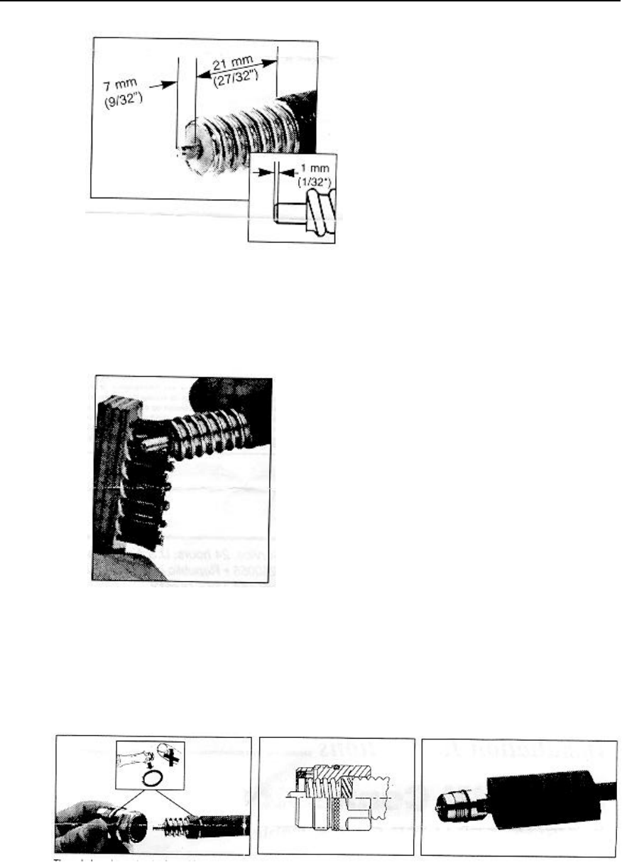
Installation Manual
iSiteC BTS3601C CDMA Base Station Hardware Installation
C Making Connectors
C-3
Figure C-4 Tapering inner conductor
7) Brush off the residuals, as shown in Figure C-5.
Figure C-5 Brushing off residuals
8) Apply grease and mount fixing nut. Place the heat-shrink tube into the cable and
then screw the fixing nut to the cable until it is tight, as shown in Figure C-6.
Figure C-6 Screwing fixing nut onto cable
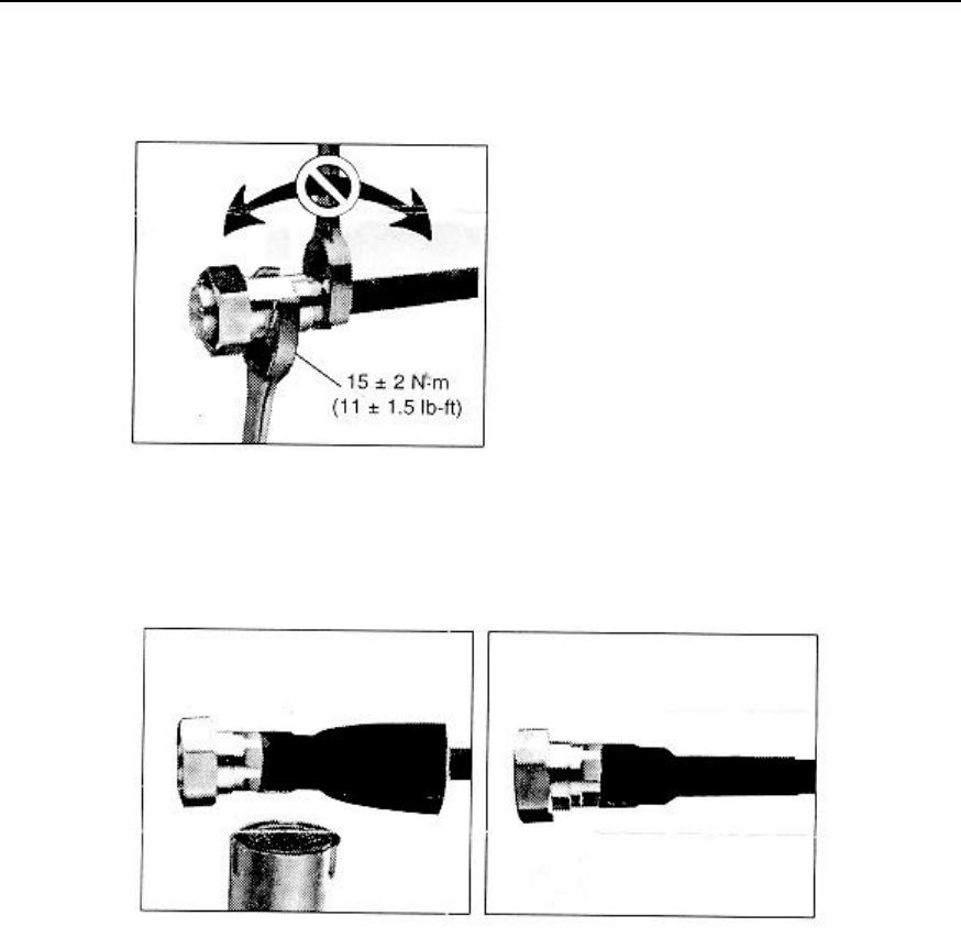
Installation Manual
iSiteC BTS3601C CDMA Base Station Hardware Installation
C Making Connectors
C-4
9) Mount the connector cap. Screw the connector cap while keeping the fixing nut still,
as shown in Figure C-7.
Figure C-7 Mounting connector cap
10) Heat up the heat-shrink tube, as shown in Figure C-8.
Figure C-8 Heating up heat-shrink tube
11) Fit torque, as shown in Figure C-9.
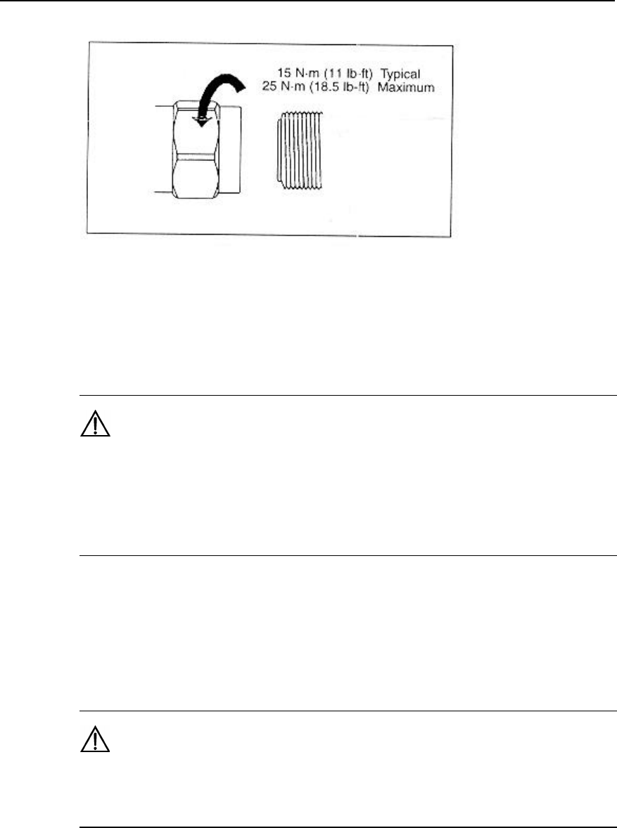
Installation Manual
iSiteC BTS3601C CDMA Base Station Hardware Installation
C Making Connectors
C-5
Figure C-9 Fitting torque
12) Be sure to test the connector after it is made. It can only be put into use after it
passes the test.
Caution:
1. Pay attention to safety during the preparation. Improper operation of sharp-edged tools can cause
human injury.
2. Be sure to clean up the feeder remainders to avoid copper scales from mixing up with the connector,
which could adversely affect the performance of the antenna and feeder system.
C.3 Making 7/16 DIN Connector and N Connector for 7/8
Feeder
Caution:
The following takes the preparation of N connector as an example. 7/16 DIN connector is prepared in the
same way.
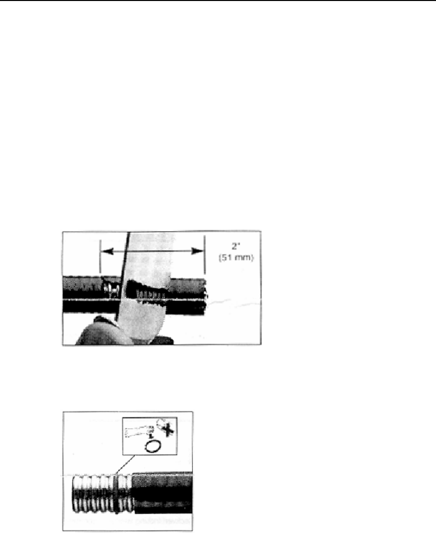
Installation Manual
iSiteC BTS3601C CDMA Base Station Hardware Installation
C Making Connectors
C-6
I. Tools required
Spanners (one is 19mm and the other is 22mm), fast cable cutter, fast cable stripper,
safety knife, electric blower, diagonal pliers, nipper pliers, pliers, file, brush and ruler
are all required.
II. Making connectors
1) Get the required tools ready and put them in a convenient place.
2) Straighten the end of the feeder to be mounted with a connector.
3) Cut the feeder with a fast cable cutter. The cutting surface should be smooth.
4) Cut the cable skin at 51mm away from the connector with the fast cable cutter and
the safety knife, as shown in Figure C-10.
5) Add O-ring and apply proper amount of grease on it, as shown in Figure C-11.
Figure C-10 Cutting cable skin
Figure C-11 Adding O-ring and applying grease
6) Add fixing nut, as shown in Figure C-12.
7) Place spring ring and fix it in the outer conductor trough of the feeder, as shown in
Figure C-13.
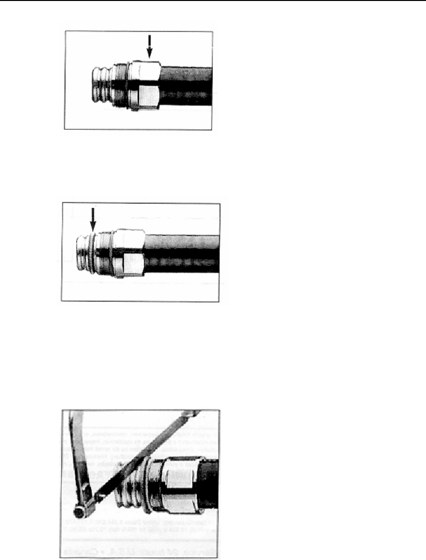
Installation Manual
iSiteC BTS3601C CDMA Base Station Hardware Installation
C Making Connectors
C-7
Figure C-12 Adding fixing nut
Figure C-13 Adding spring ring
8) Adjust the hacksaw and the hacksaw guide (big washer) to cut the cable, as
shown in Figure C-14.
9) Brush off the burr and residuals, as shown in Figure C-15.
Figure C-14 Cutting cable
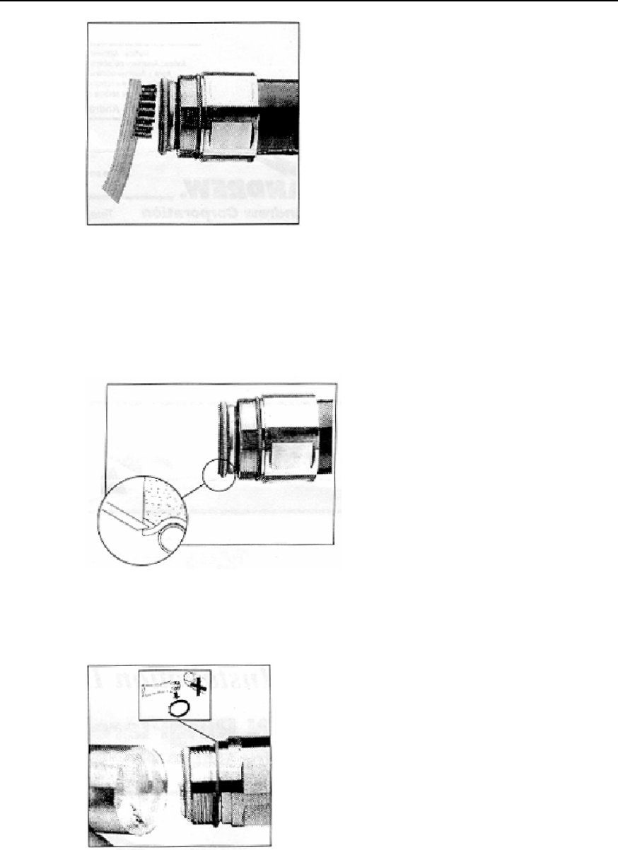
Installation Manual
iSiteC BTS3601C CDMA Base Station Hardware Installation
C Making Connectors
C-8
Figure C-15 Brushing off residuals
10) Press the foam plastic tightly, as shown in Figure C-16.
11) Add O-ring and apply grease to it. Mount the connector body, as shown in Figure
C-17.
Figure C-16 Pressing foam plastic tightly
Figure C-17 Mounting connector body
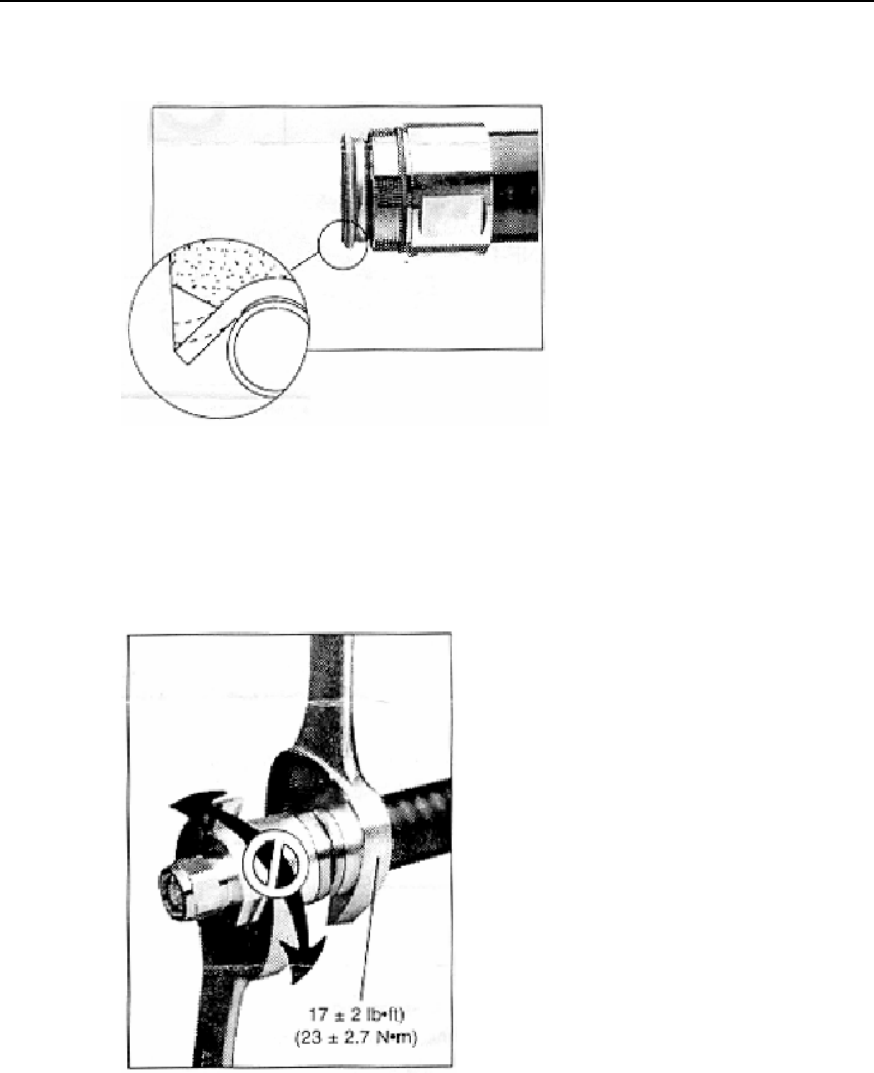
Installation Manual
iSiteC BTS3601C CDMA Base Station Hardware Installation
C Making Connectors
C-9
12) Expand the outer conductor with a fast cable stripper (fitting the feeder type).
Check the stretching surface and clean off the residuals, as shown in Figure C-18.
Figure C-18 Stretching outer conductor
13) Refit the connector. Never rotate the connector body while installing, as shown in
Figure C-19.
14) Fit the torque, as shown in Figure C-20.
Figure C-19 Fitting connector
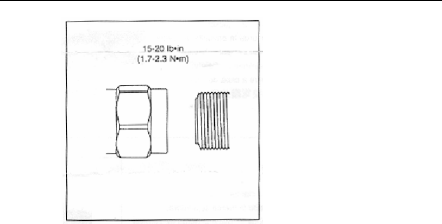
Installation Manual
iSiteC BTS3601C CDMA Base Station Hardware Installation
C Making Connectors
C-10
Figure C-20 Fitting torque

Installation Manual
iSiteC BTS3601C CDMA Base Station Hardware Installation
D Preparing Grounding Clips
D-1
D Preparing Grounding Clips
D.1 Overview
During the entire installation, there are many places where grounding clips should be
applied. The following is the summary of the places where grounding clips are required.
1) Normally, each feeder should be grounded at the following three points at least for
lightning-protection:
l Within 1m's reach behind the place where the feeder is led from the tower
platform;
l Within 1m's reach in front of the place where the feeder is led from the tower body
to the outdoor cabling rack;
l At the outer side of the feeder window before which the feeder is led into (on the
spot).
When the length of the feeder along the tower body exceeds 60m, more
lightning-protection grounding clips should be added in the middle of the tower body.
Typically, one clip is installed for every 20m.
2) If the feeder is led into the room after being routed for a stretch of distance on the
building-top, and the distance exceeds 20m, a lightning-protection grounding clip
is required on the top of the building.
3) For the feeder that enters the room from the building-top along the wall, if an
outdoor cabling rack is used, the cabling rack should also be grounded.
D.2 Preparation Process
1) Prepare the required tools, such as paper cutter, flat screwdriver and nipper pliers,
etc.
2) Unpack the box and bags containing the lightning-protection grounding clips and
put various parts and accessories on clean ground or paper for use, as shown in
Figure D-1.
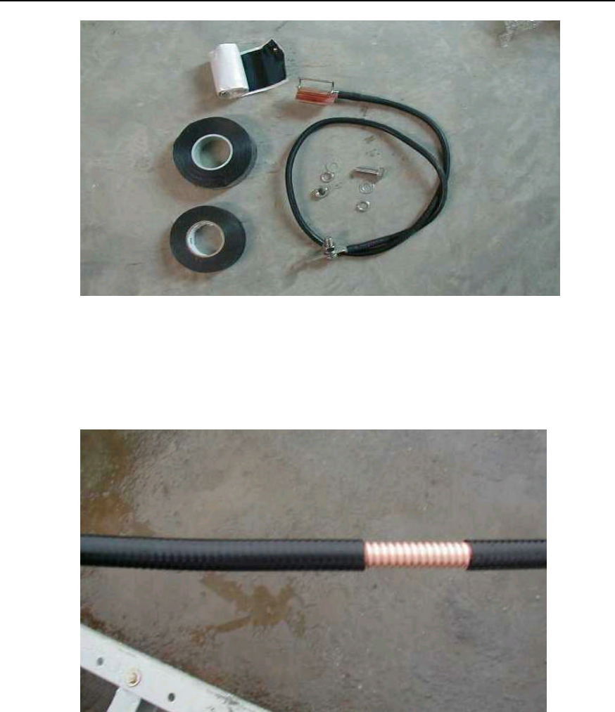
Installation Manual
iSiteC BTS3601C CDMA Base Station Hardware Installation
D Preparing Grounding Clips
D-2
Figure D-1 Installation accessories of lightning-protection grounding clips
3) Determine the location for lightning-protection grounding clip installation. Cut the
feeder skin according to the clip size to expose the outer conductor, as shown in
Figure D-2.
Figure D-2 Striping off feeder skin
4) Fix the lightning-protection grounding clip on the feeder. The grounding cable of
the clip should be led from the top down with the angle between the feeder and the
grounding cable not greater than 15°, as shown in Figure D-3.
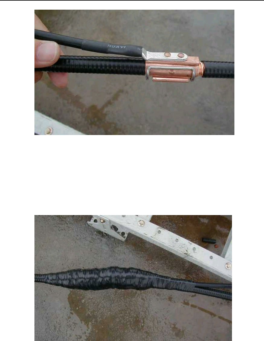
Installation Manual
iSiteC BTS3601C CDMA Base Station Hardware Installation
D Preparing Grounding Clips
D-3
Figure D-3 Lightning protection grounding clip fixed on feeder
5) Wrap up the lightning protection grounding clip with PVC tape, semi-conductive
self-adhesive tape and waterproof tape in turn. When wrapping, do it from the
bottom up, then from the top down and finally from the bottom up again. Each turn
should be overlapped by the next turn for about one-third of the width as shown in
Figure D-4.
Figure D-4 Wrapping lightning protection grounding clip with three layers of tapes
6) The sealed lightning protection grounding clip can be connected to the outdoor
grounding bar, as shown in Figure D-5, as well as to the well-grounded outdoor
cabling rack. The grounding clip in Figure D-4 is connected to the outdoor cabling
rack. When the lightning protection grounding clip is connected to the outdoor
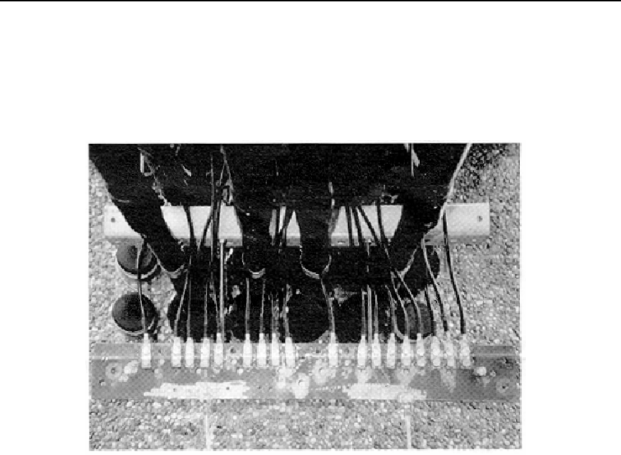
Installation Manual
iSiteC BTS3601C CDMA Base Station Hardware Installation
D Preparing Grounding Clips
D-4
cabling rack, the anti-rust paint at the place where the rack is grounded should be
removed. When the grounding cables are installed, the place should be covered
with anti-rust paint again. Those exposed connector parts should also be painted
with anti-rust paint for good grounding, if they are incapable of being wrapped up
with insulating tapes.
Figure D-5 Lightning protection grounding clip connected to outdoor grounding bar