Huawei Technologies BTS3612A-1900 CDMA Base Station User Manual Part 3
Huawei Technologies Co.,Ltd CDMA Base Station Part 3
UserManual.wiki
>
Huawei Technologies
>
BTS3612A-1900 User Manual
>
User Manual Part 3
Contents
1.
User Manual Part 1
2.
User Manual Part 2
3.
User Manual Part 3
User Manual Part 3
Navigation menu
Upload a User Manual
Namespaces
Wiki Guide
HTML
PDF
Info
Views
User Manual
Discussion / Help
Navigation
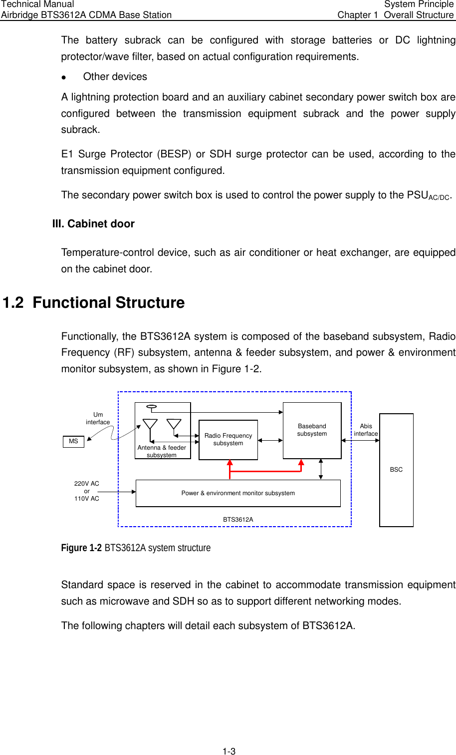
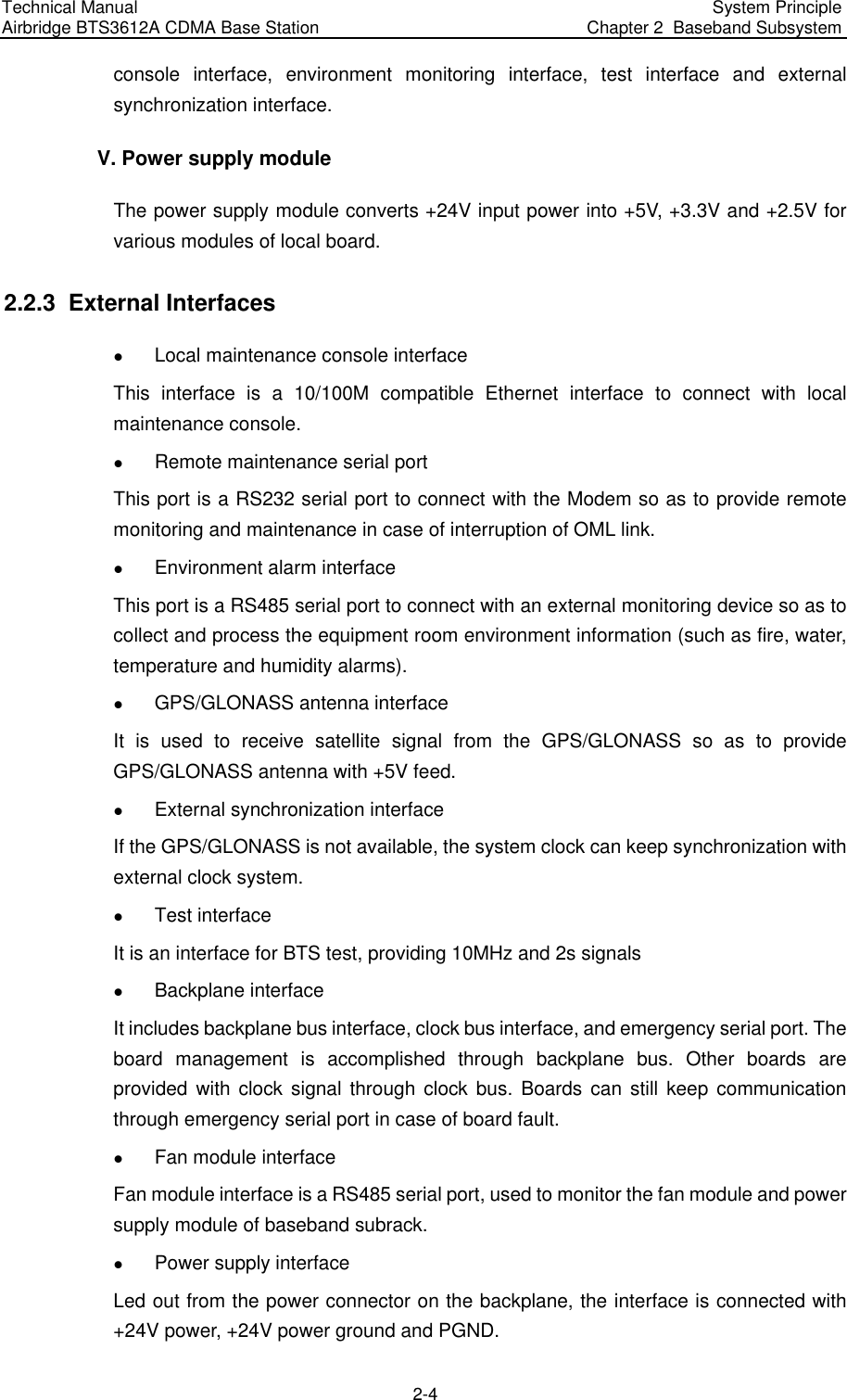
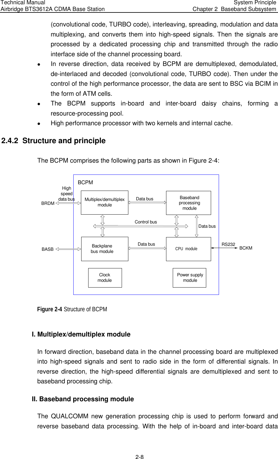
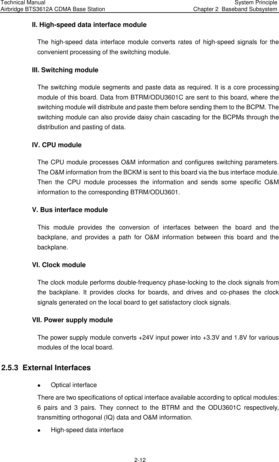
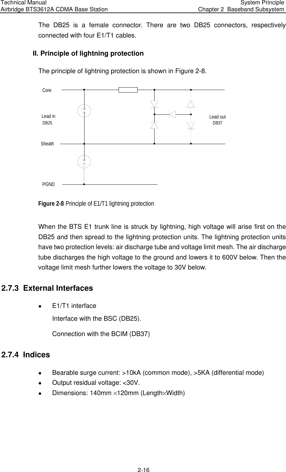
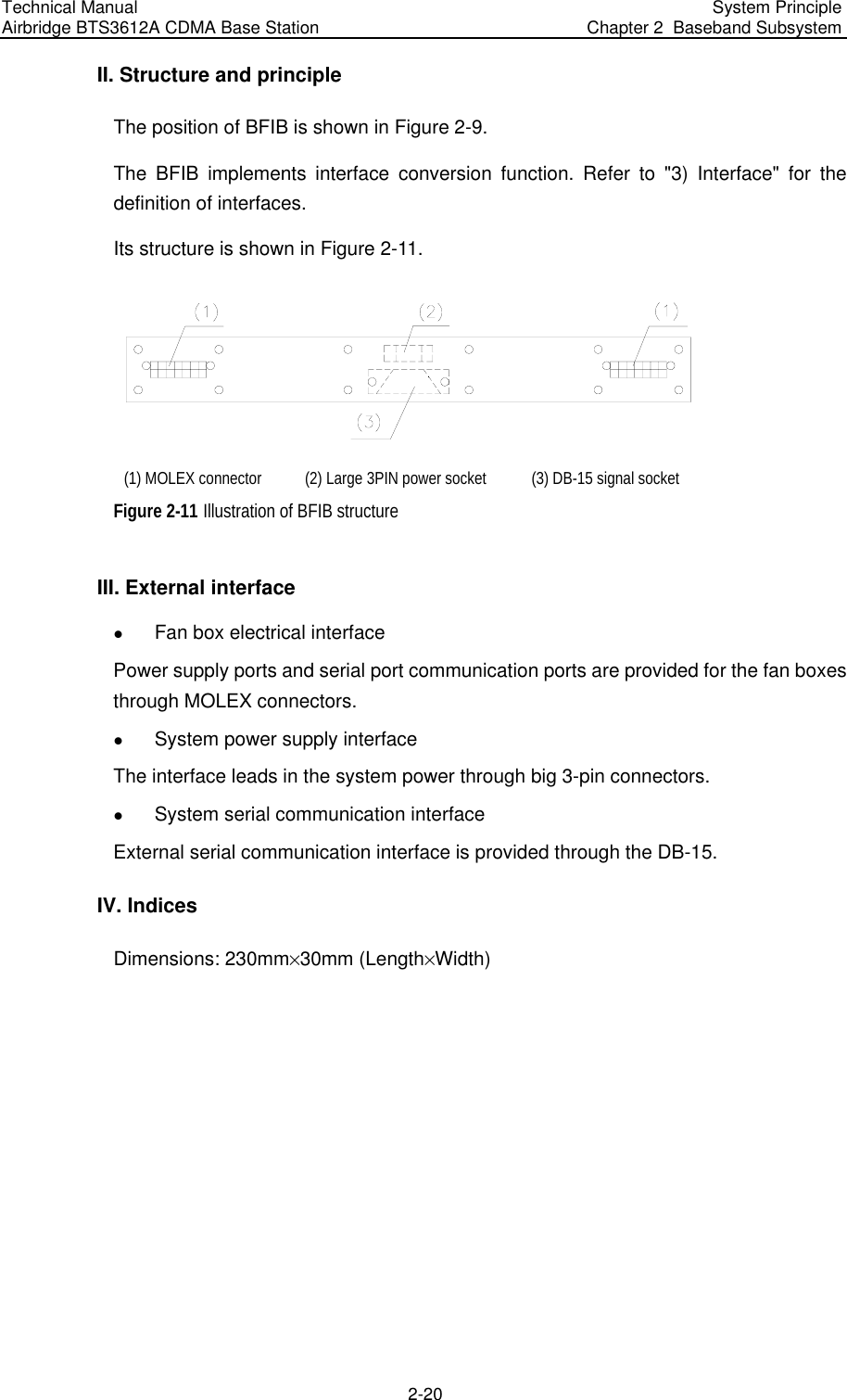
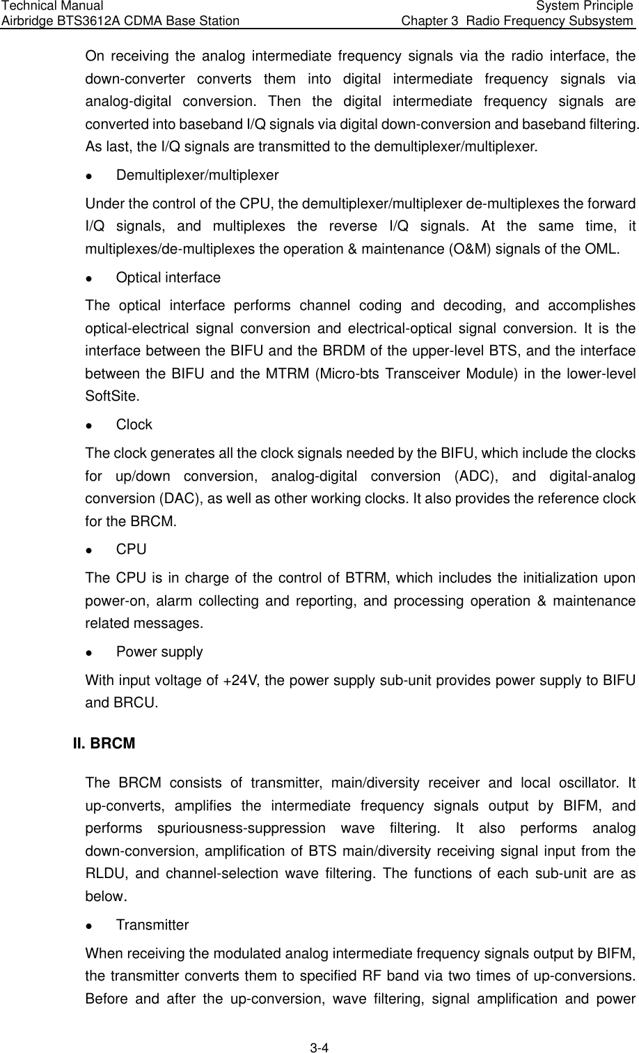
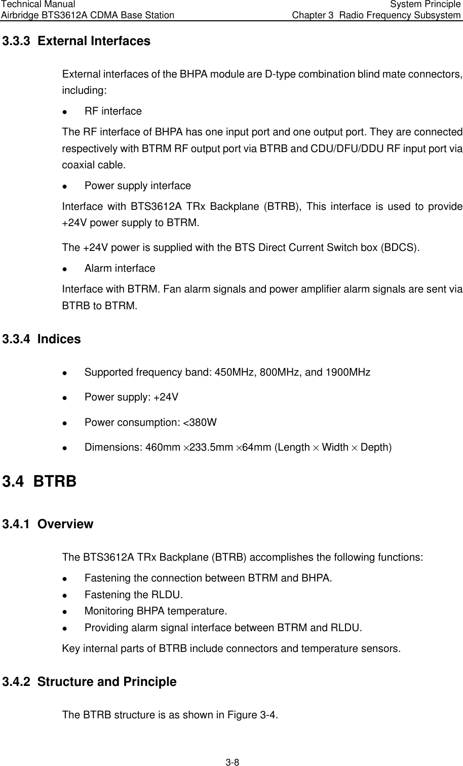
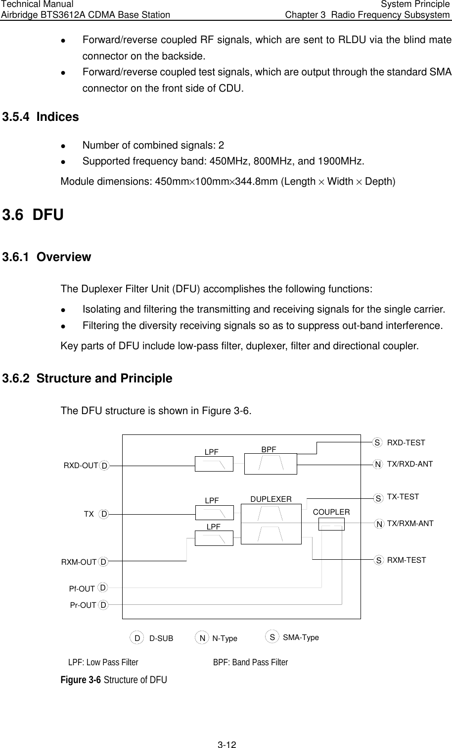
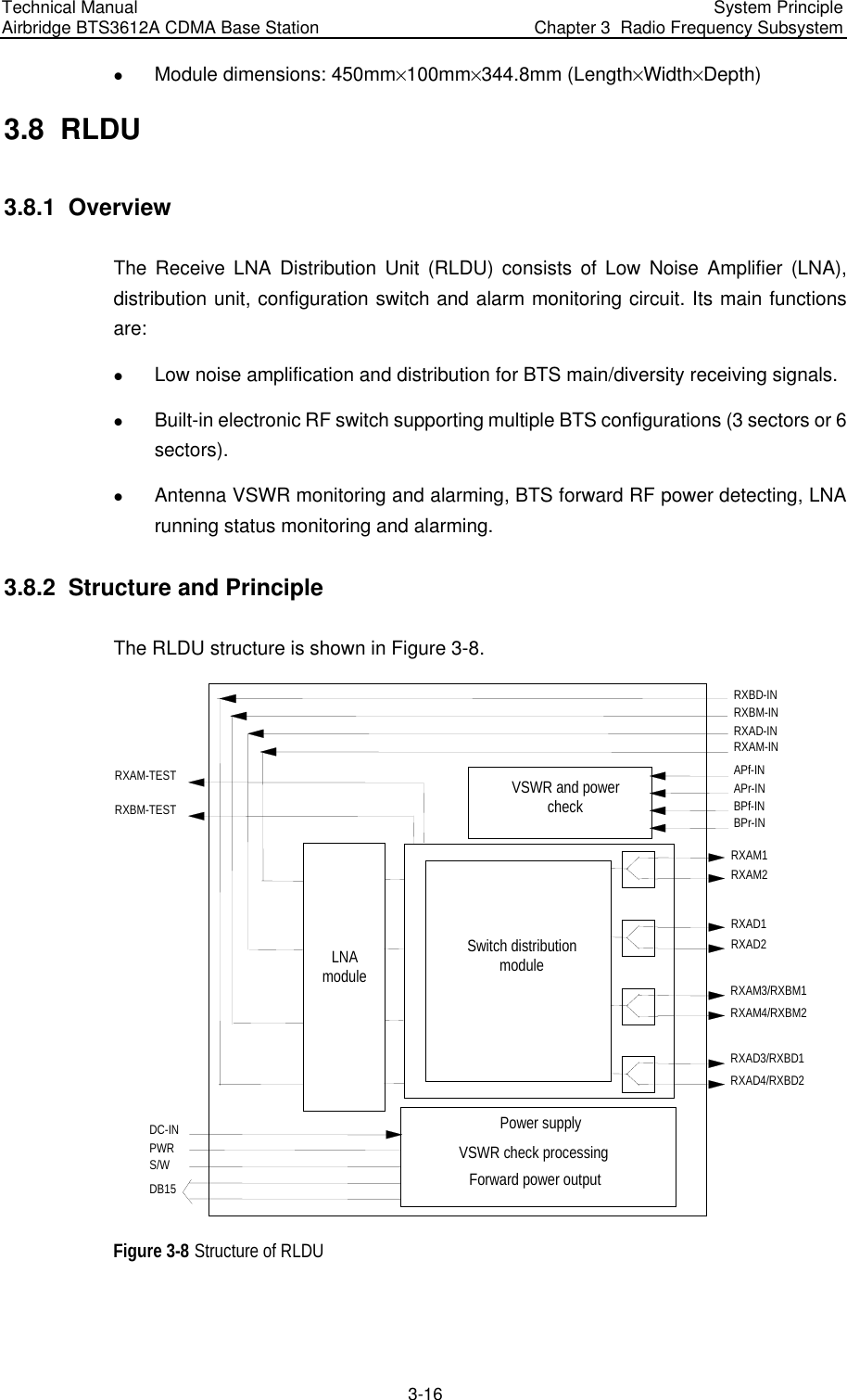
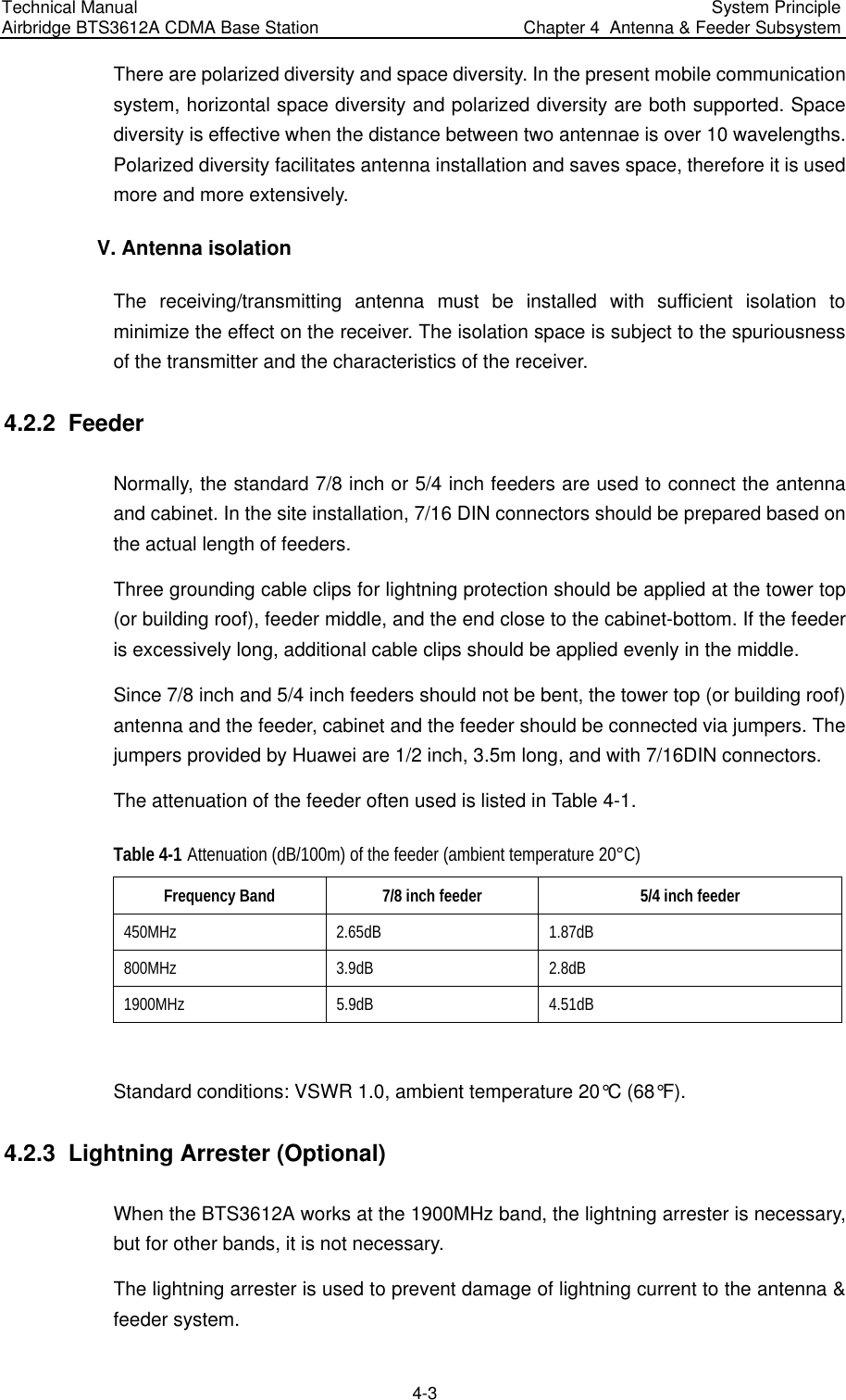
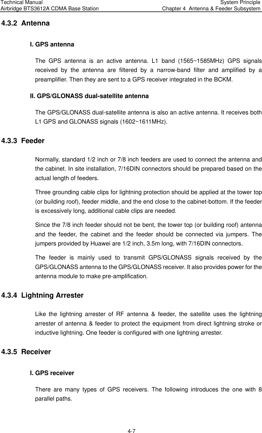
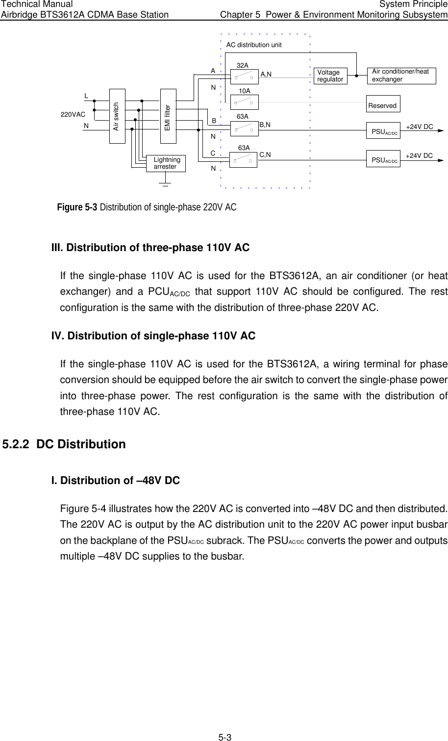
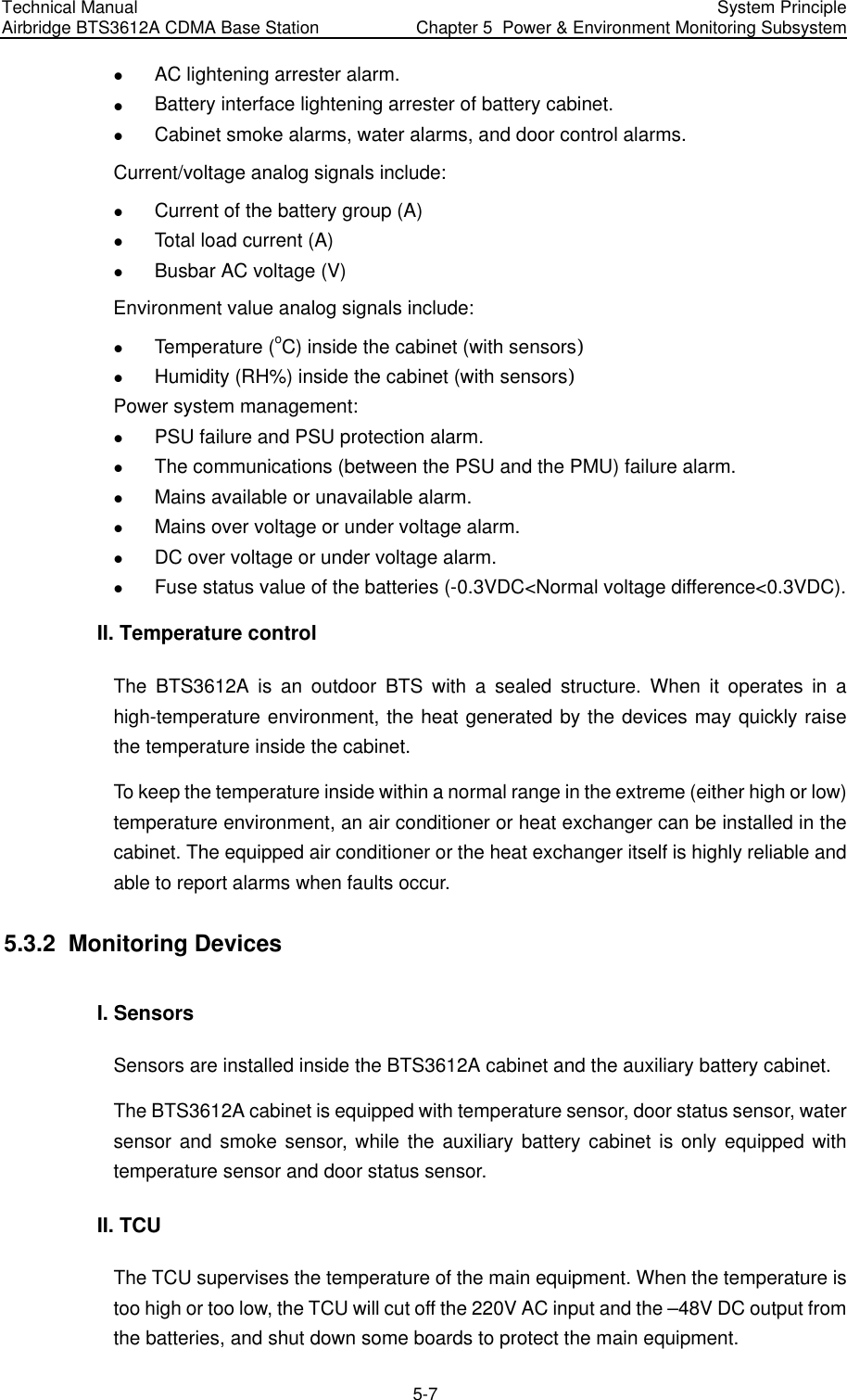
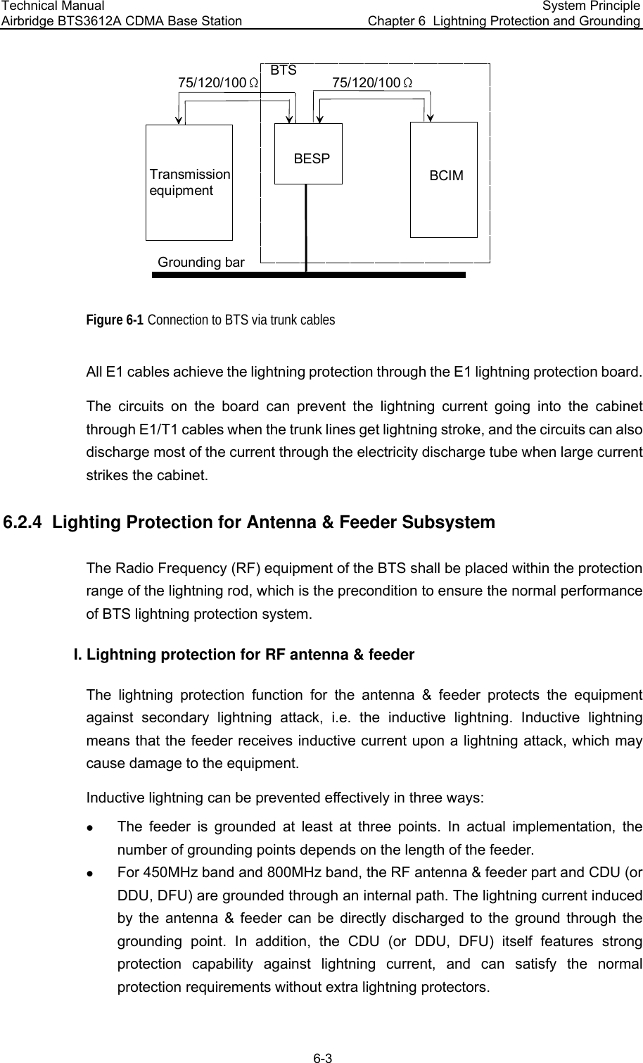
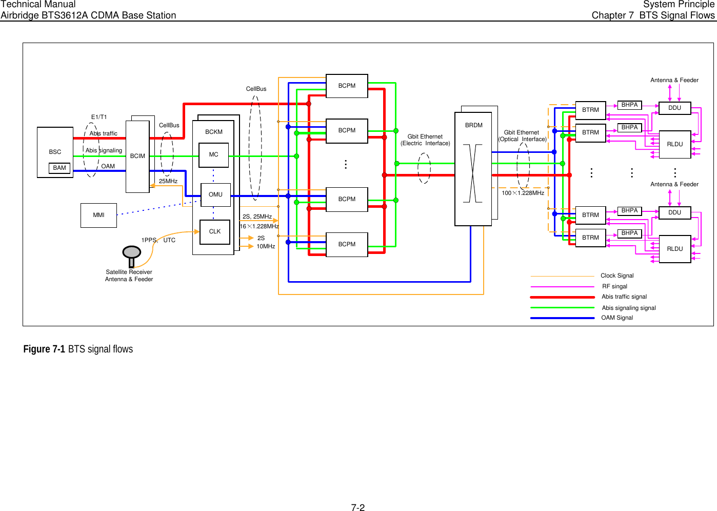
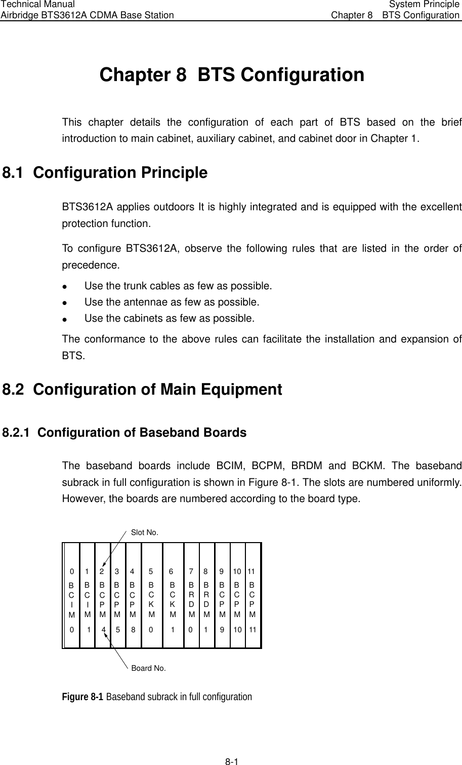
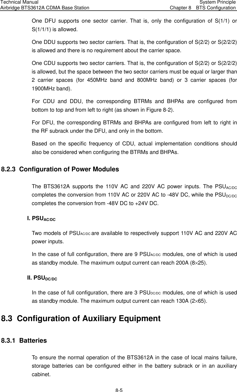
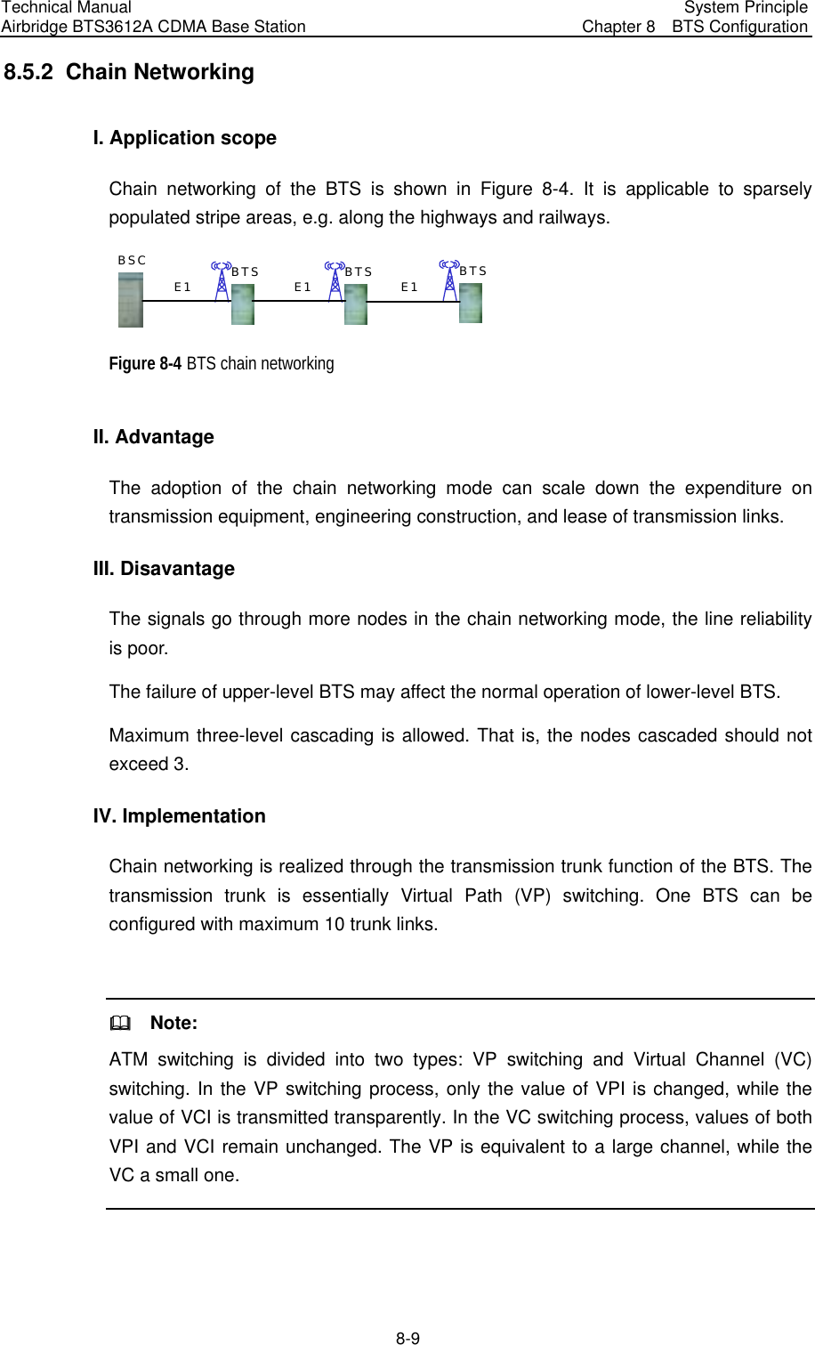
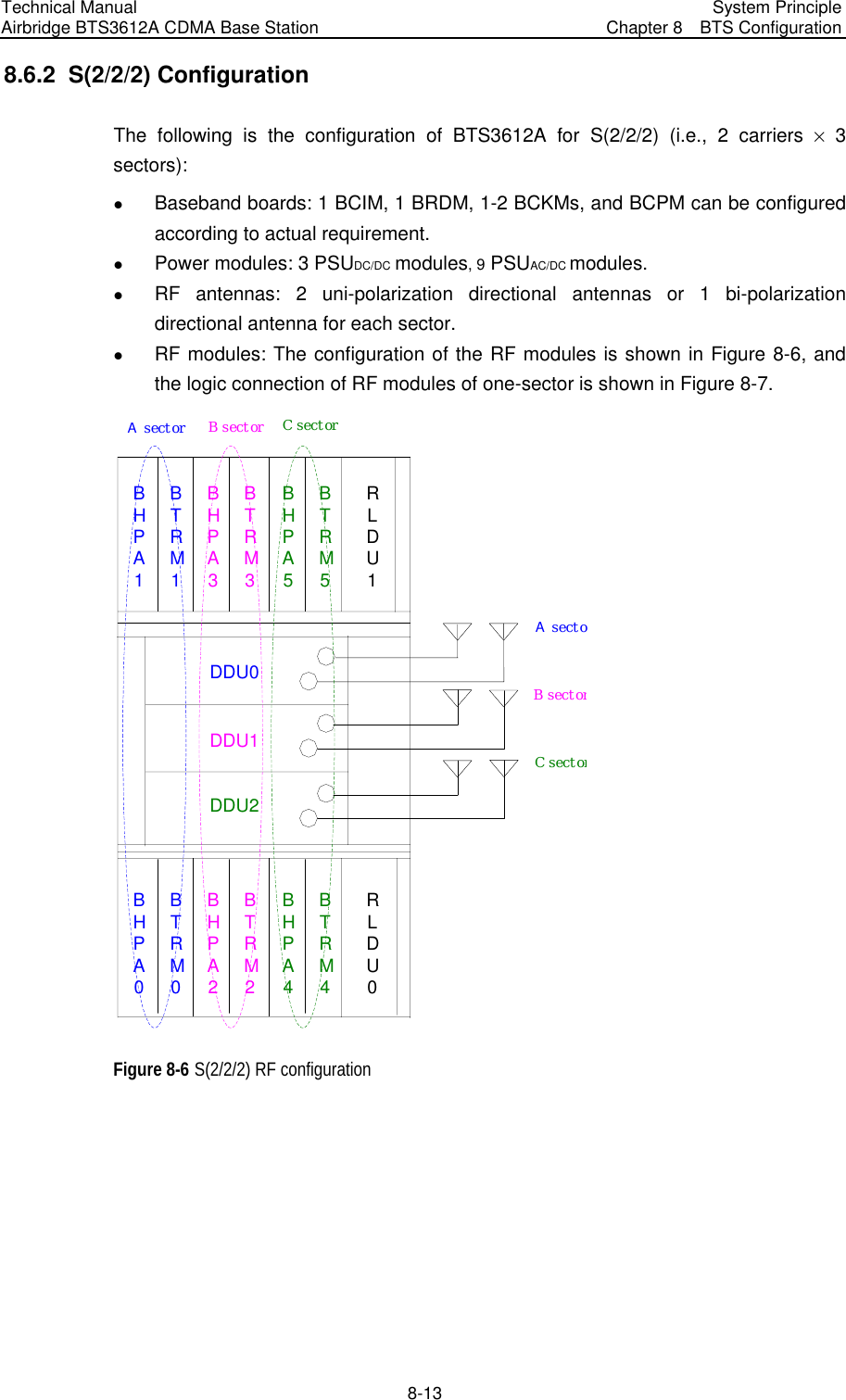
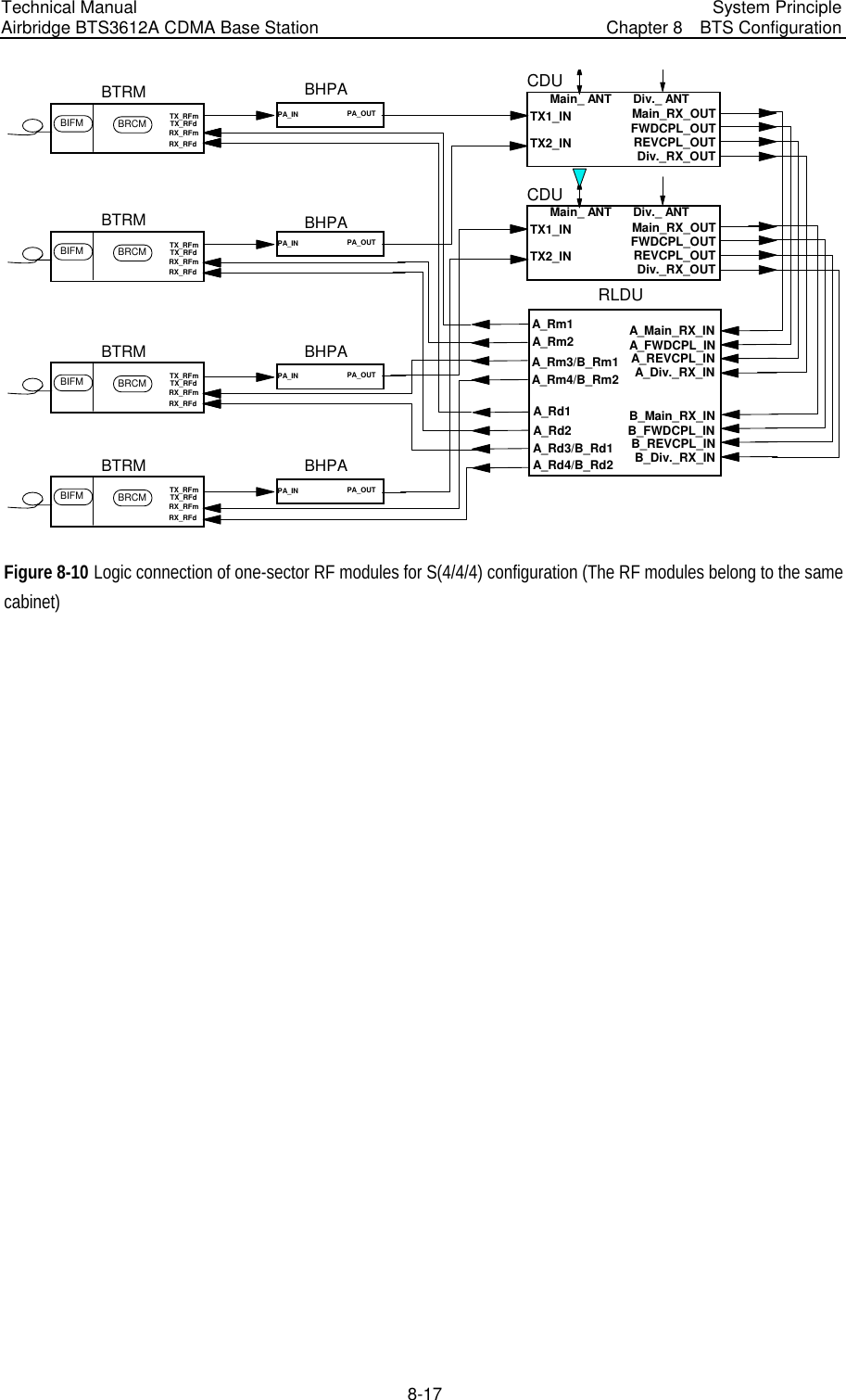
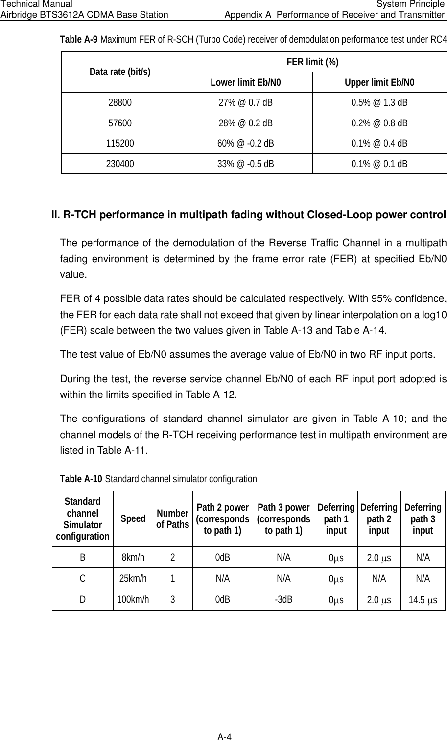
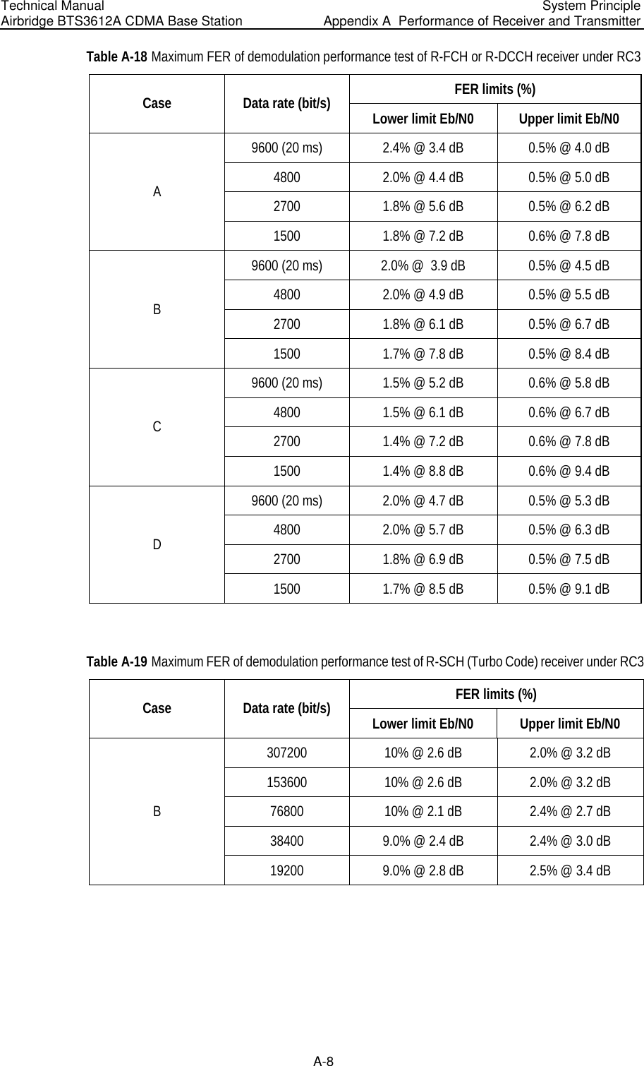
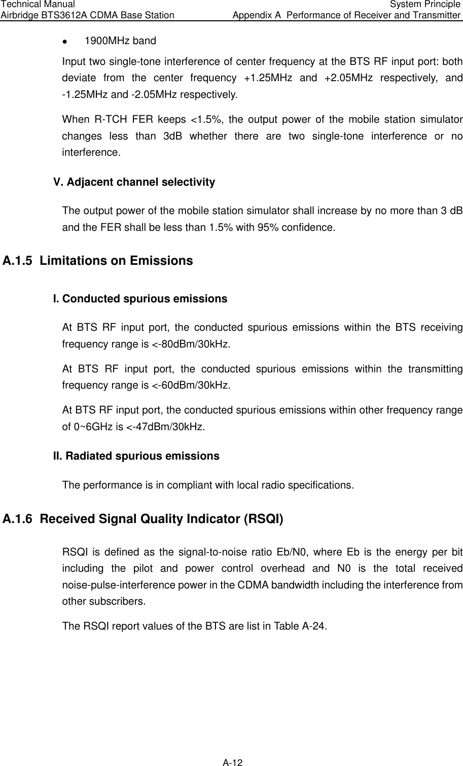
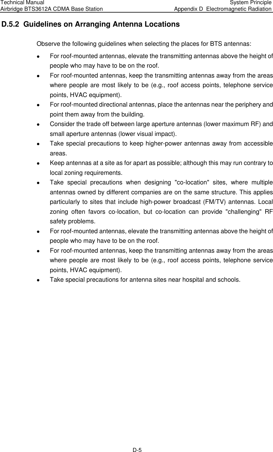
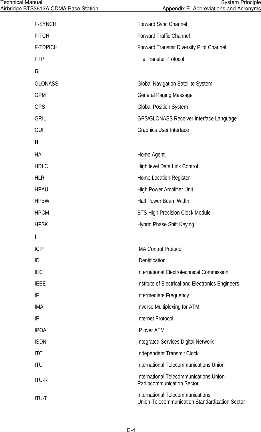
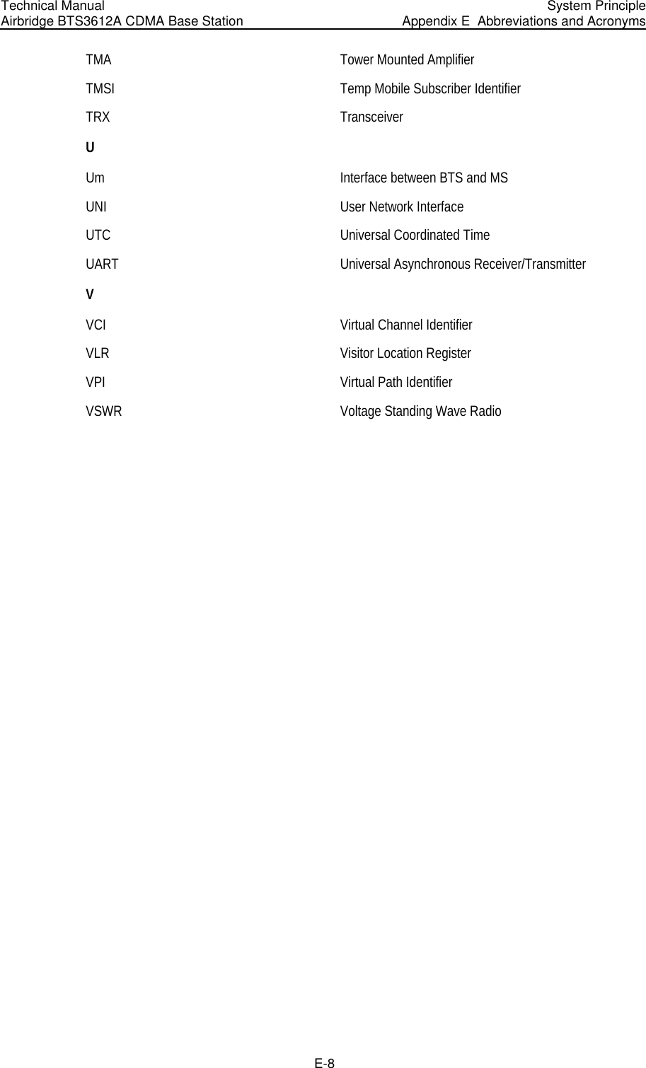
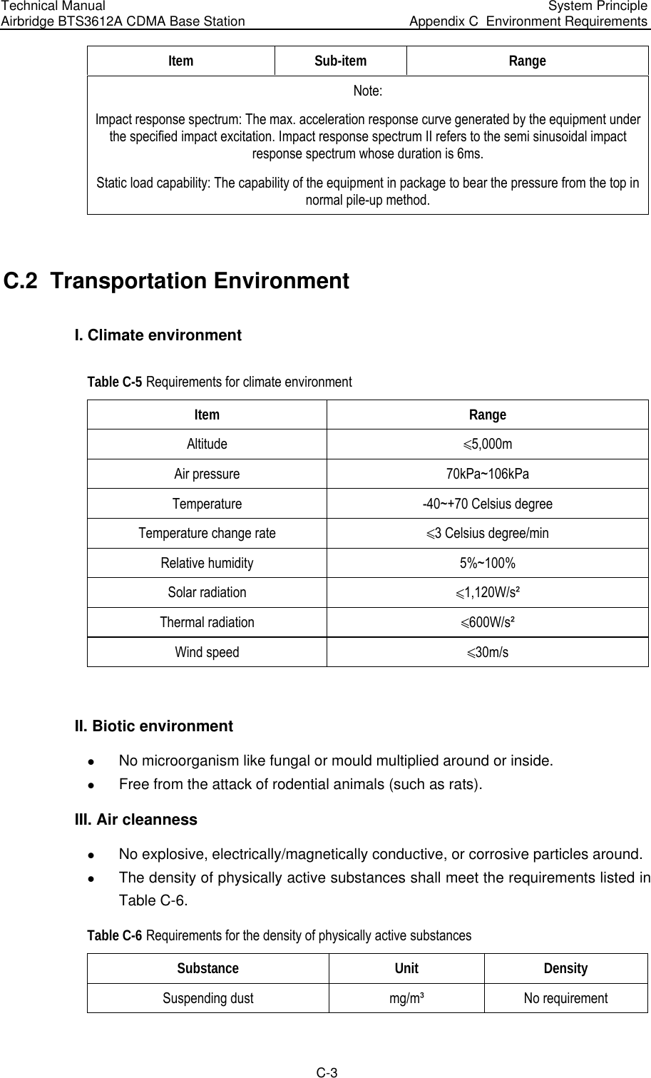
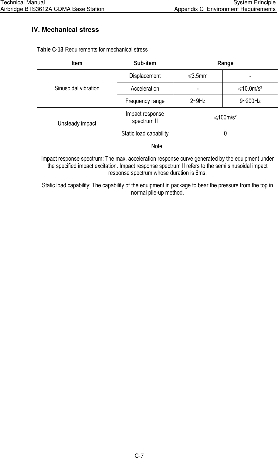
![Technical Manual Airbridge BTS3612A CDMA Base Station System Principle Appendix B EMC Performance B-1 Appendix B EMC Performance ETSI EN 300 386 Electromagnetic Compatibility and Radio Spectrum Matters (ERM); Telecommunication network Equipment; ElectroMagnetic Compatibility (EMC) Requirements are the international EMC standards. The EMC performance of BTS3612A complies with ETSI EN 300 386 V1.2.1 (2000-03). They are described in two aspects: ElectroMagnetic Interference (EMI) and ElectroMagnetic Sensitivity (EMS). B.1 EMI Performance I. Conductive Emission (CE) at DC input/output port CE indices are listed in Table B-1. Table B-1 CE indices at -48V port Threshold (dB µV) Frequency range Average Quasi-peak 0.15 ~ 0.5MHz 0.5 ~ 5MHz 5 ~ 30MHz 56~46 46 50 66~56 56 60 II. Radiated Emission (RE) RE indices are listed in Table B-2. Table B-2 RE indices Band (MHz) Threshold of quasi-peak (dB µV/m) 30 ~ 1000 61.5 1000 ~ 12700 67.5 Note: Test field is arranged according to ITU-R 329-7 [1].](https://usermanual.wiki/Huawei-Technologies/BTS3612A-1900.User-Manual-Part-3/User-Guide-384040-Page-109.png)
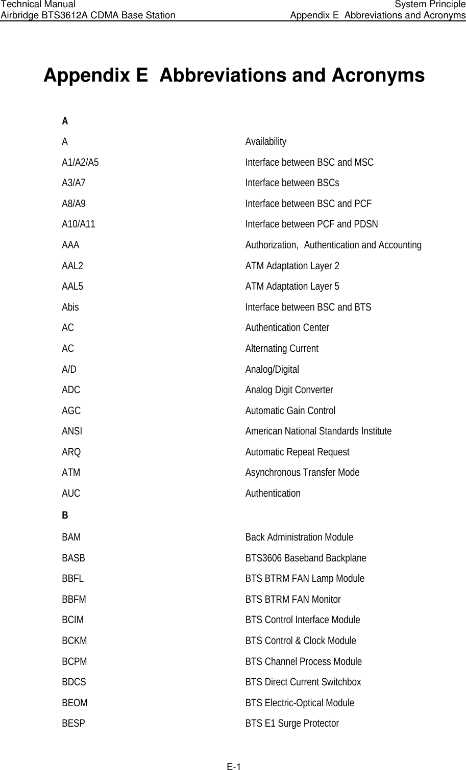
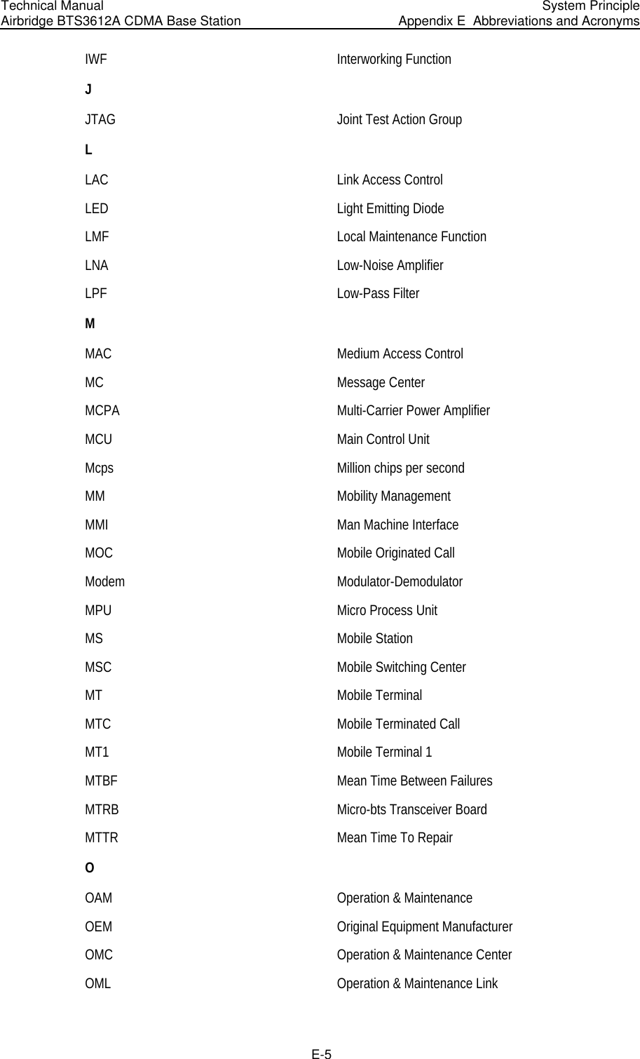
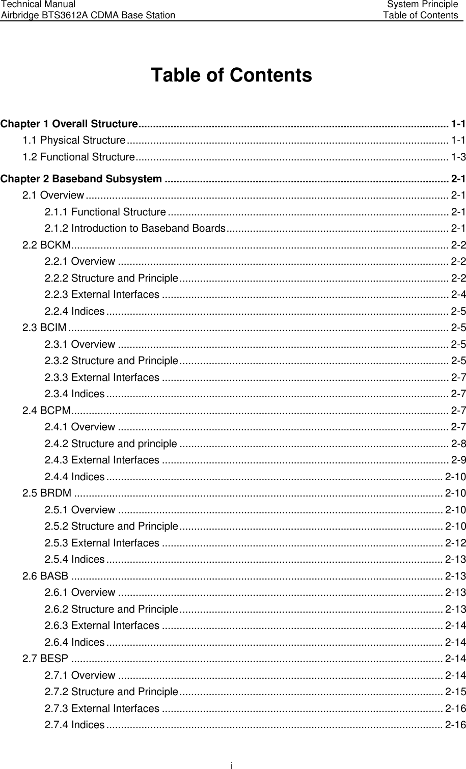
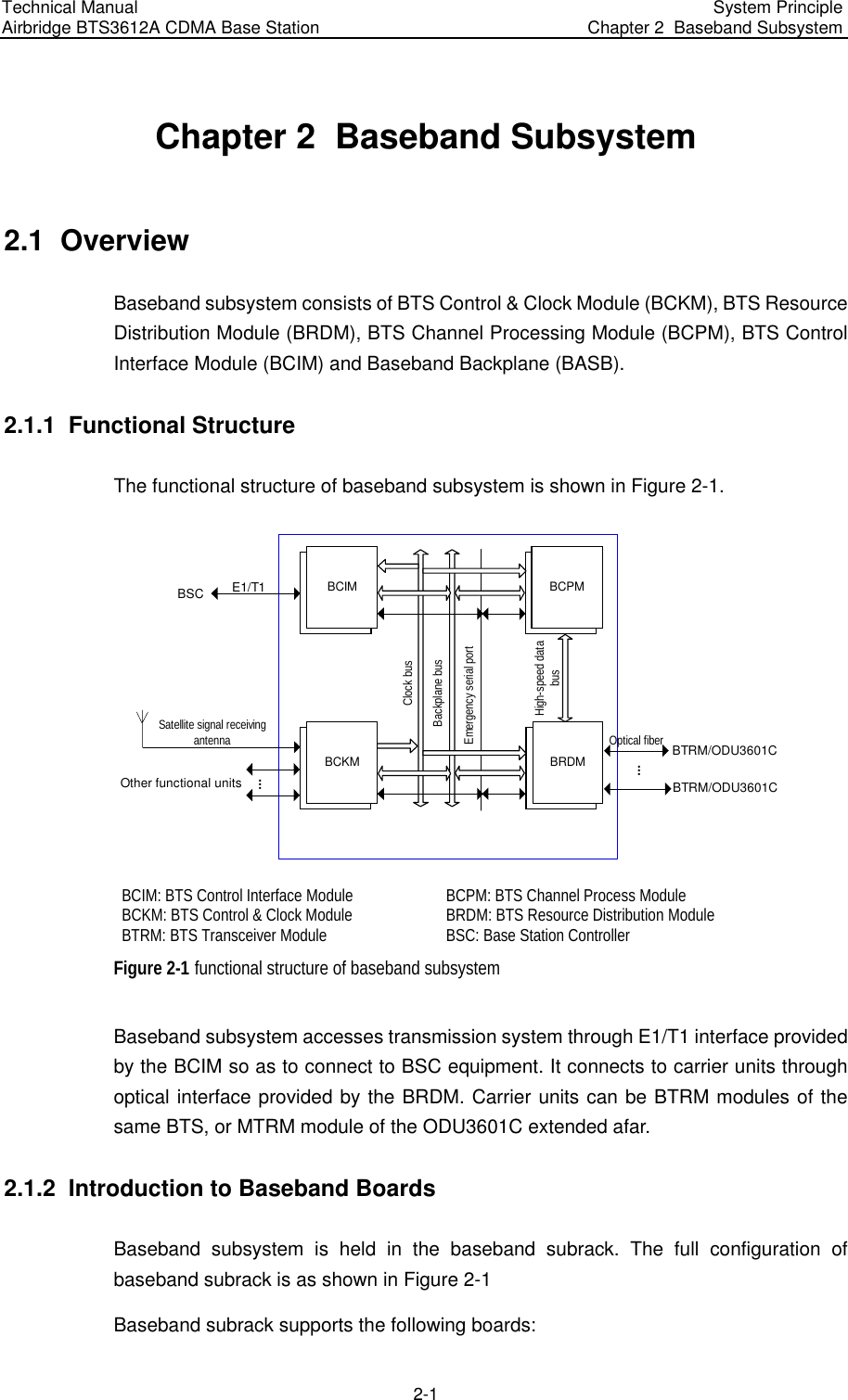
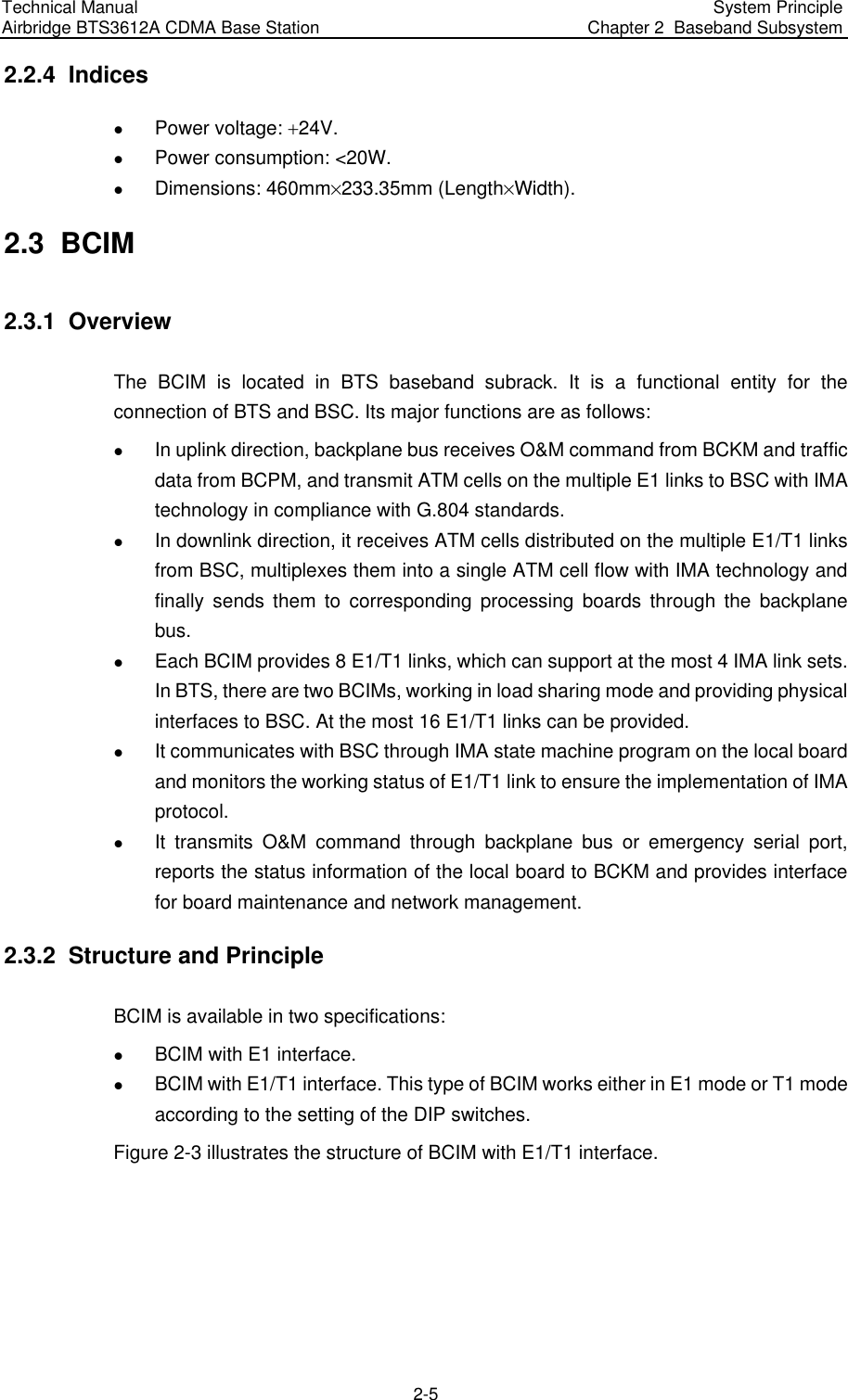
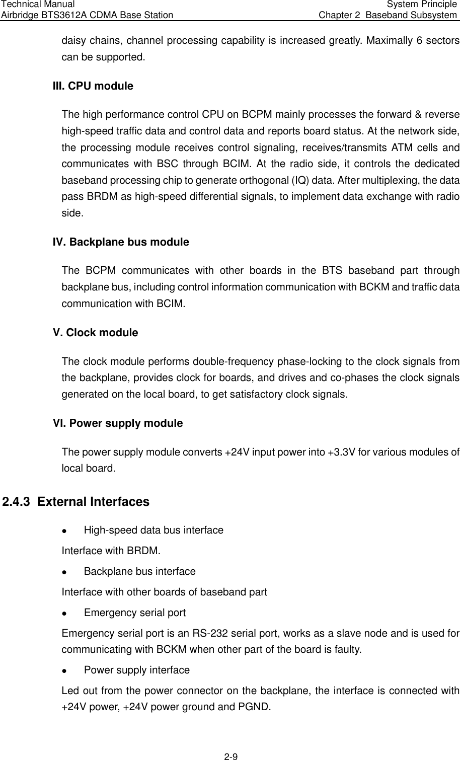
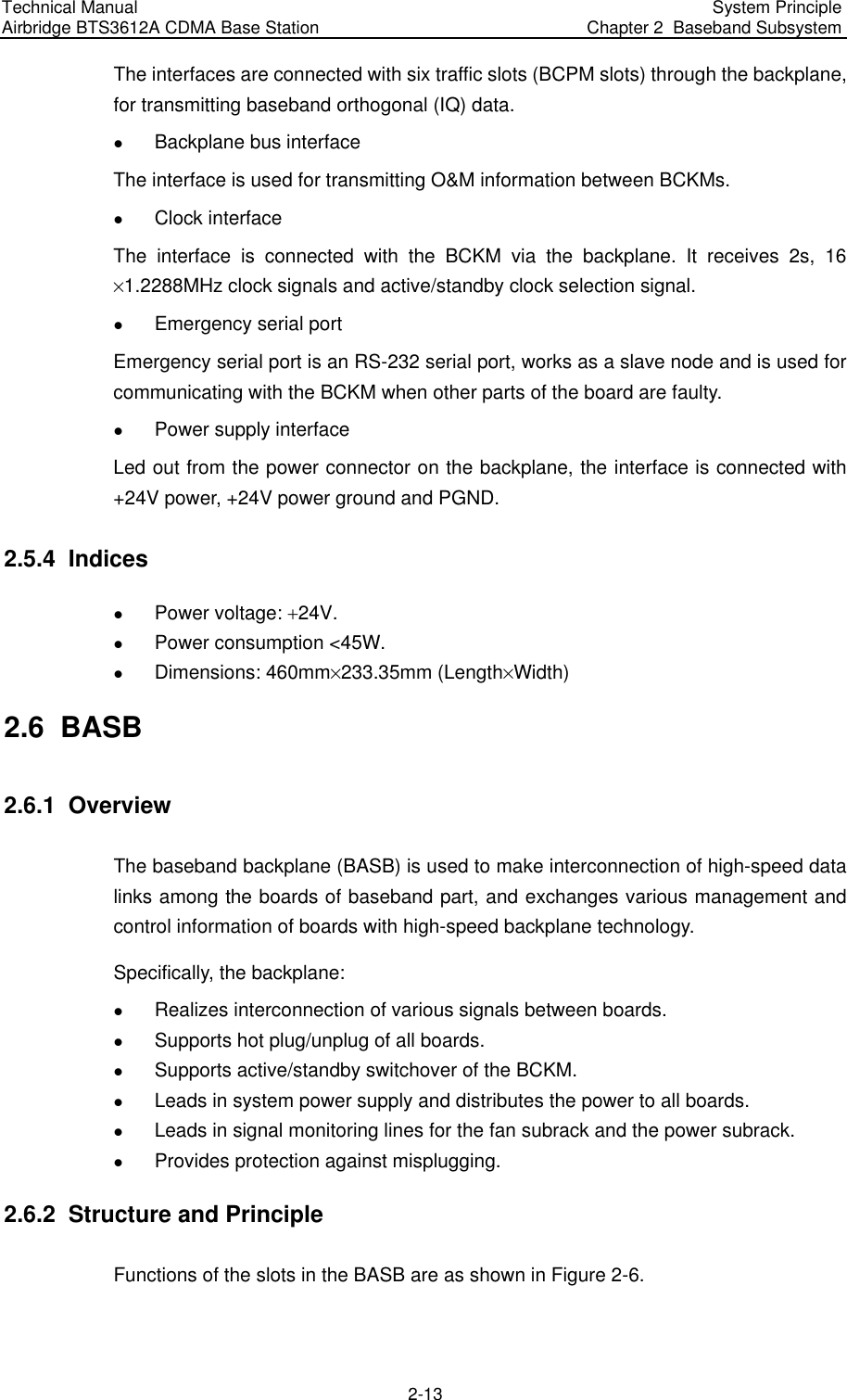
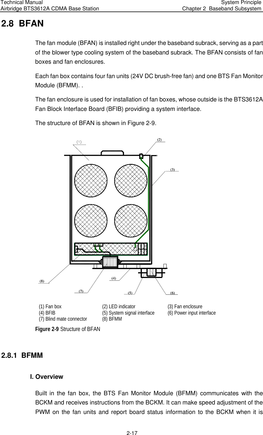
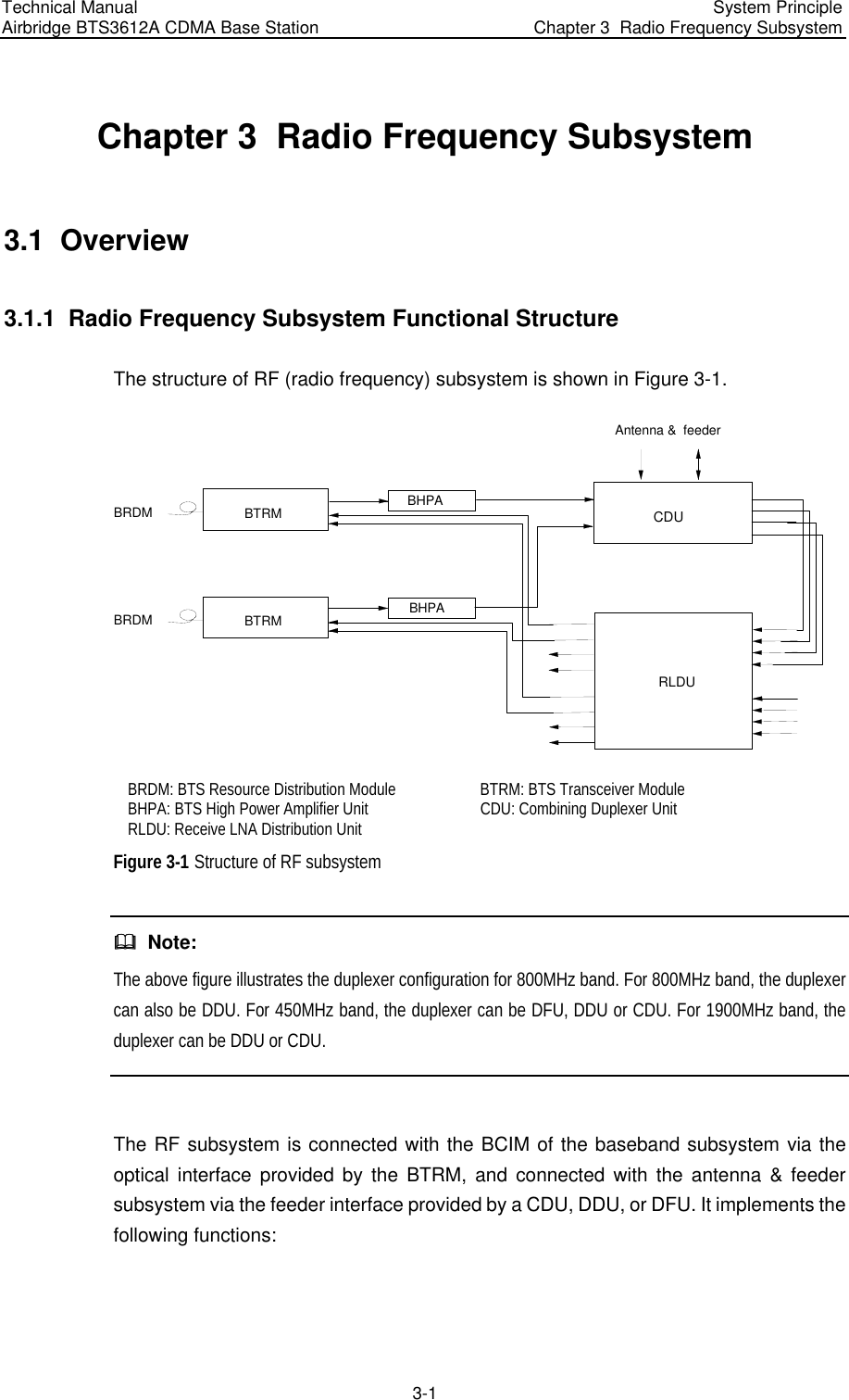
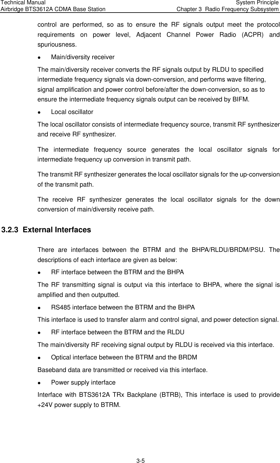
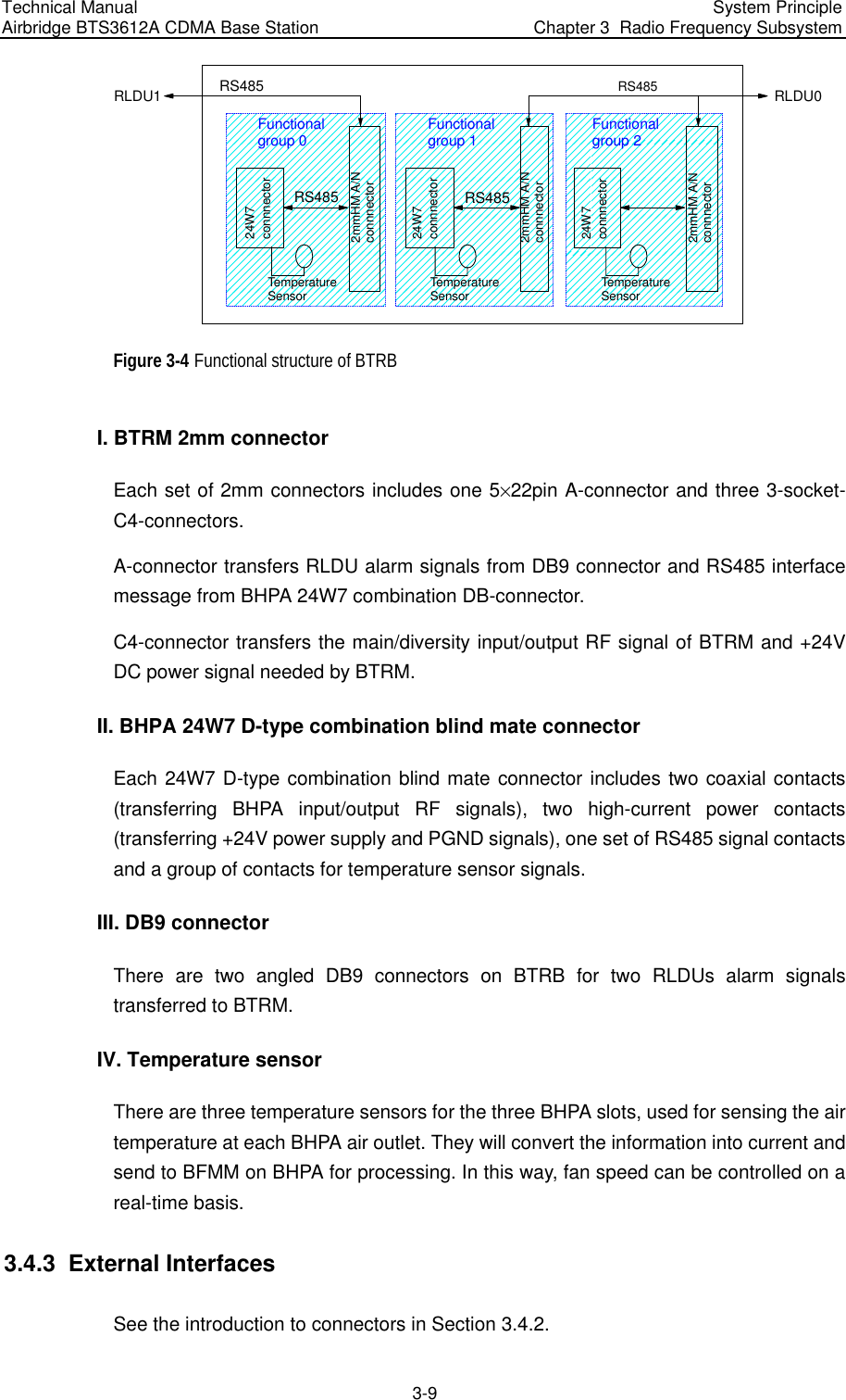
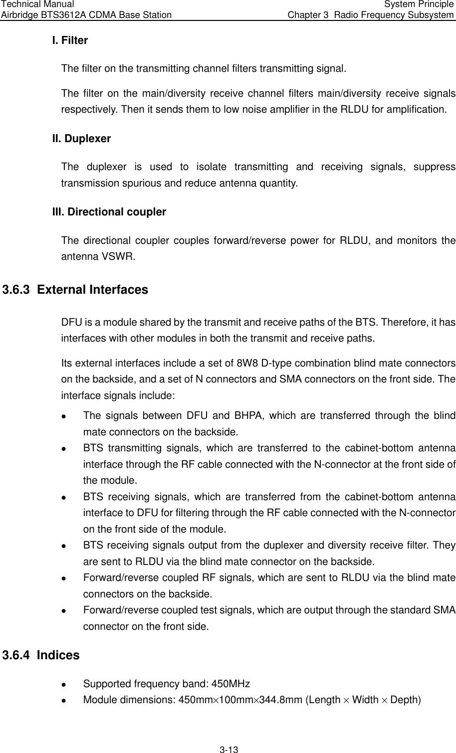
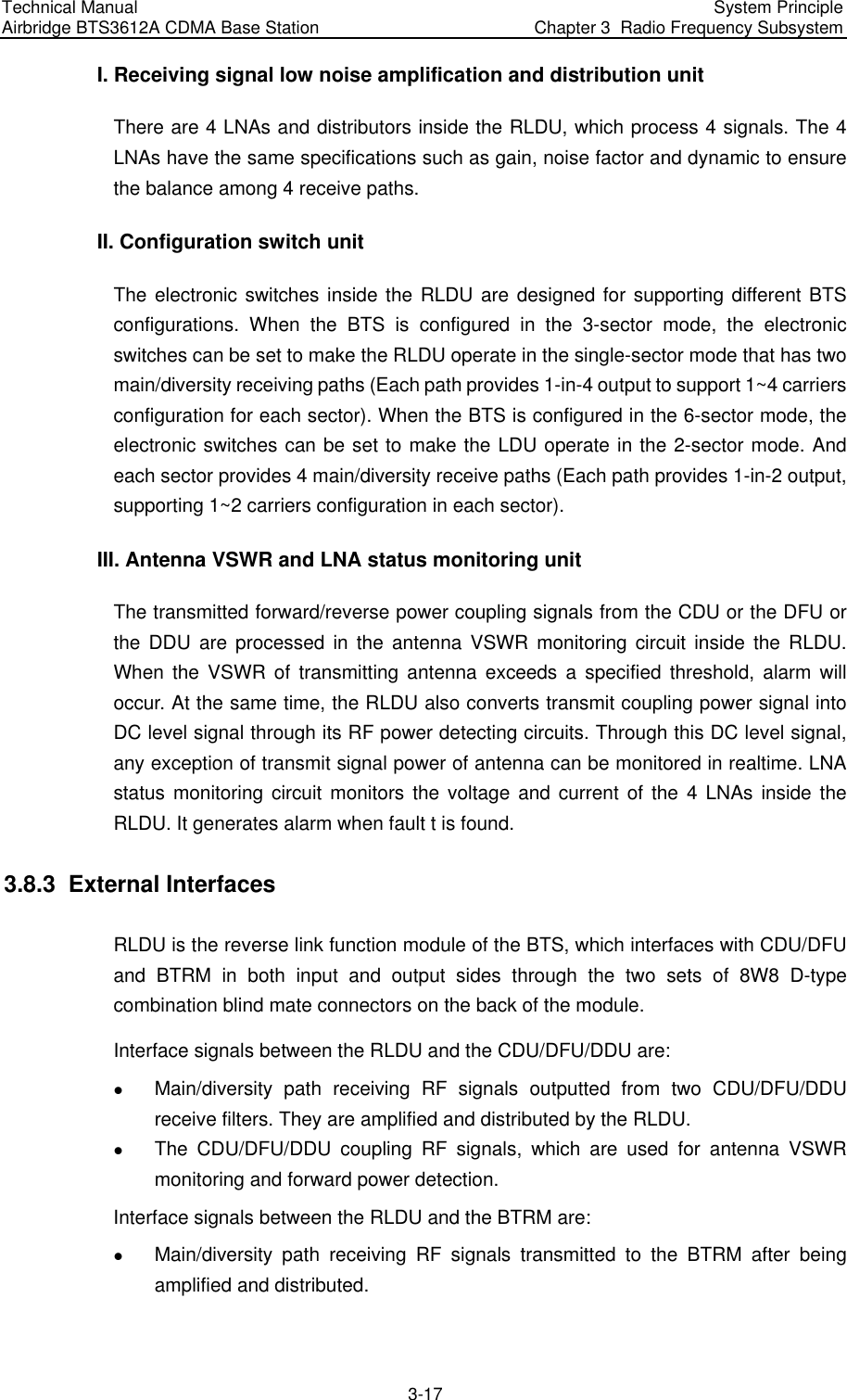
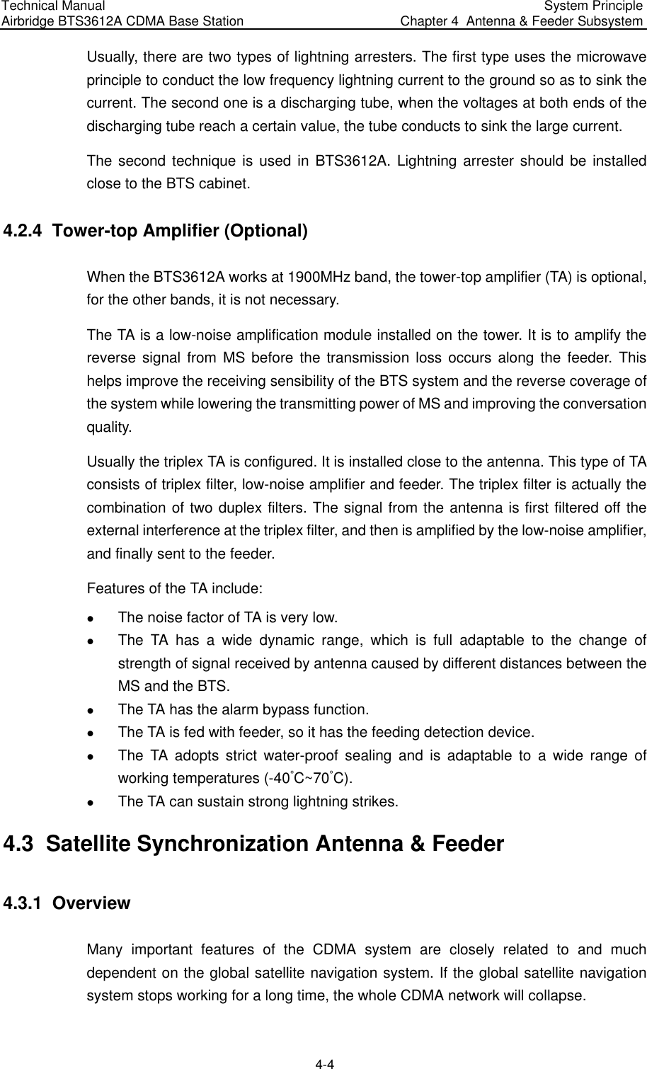
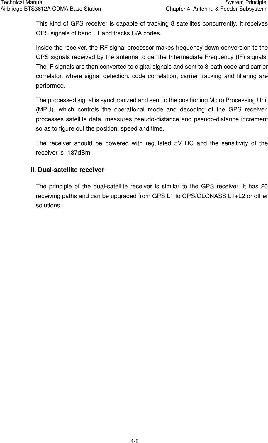
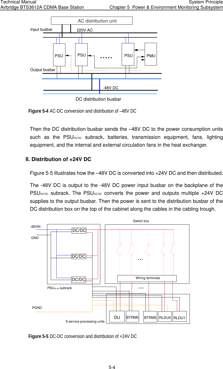
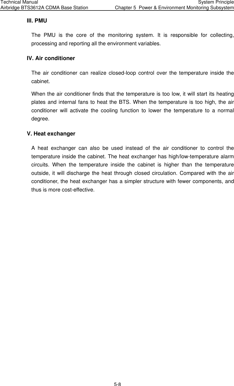
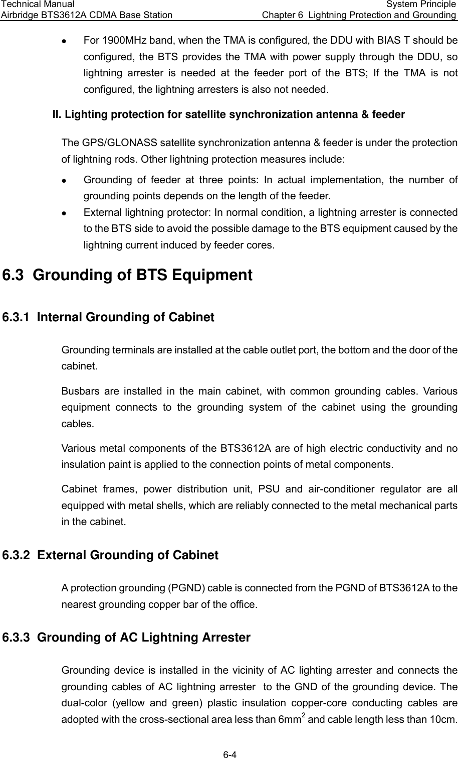
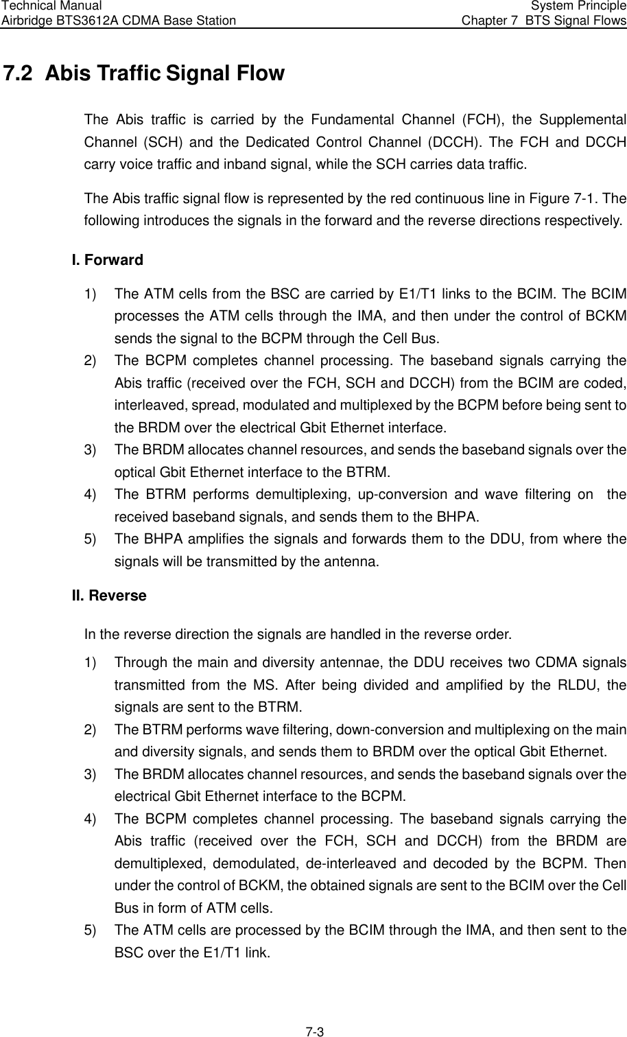
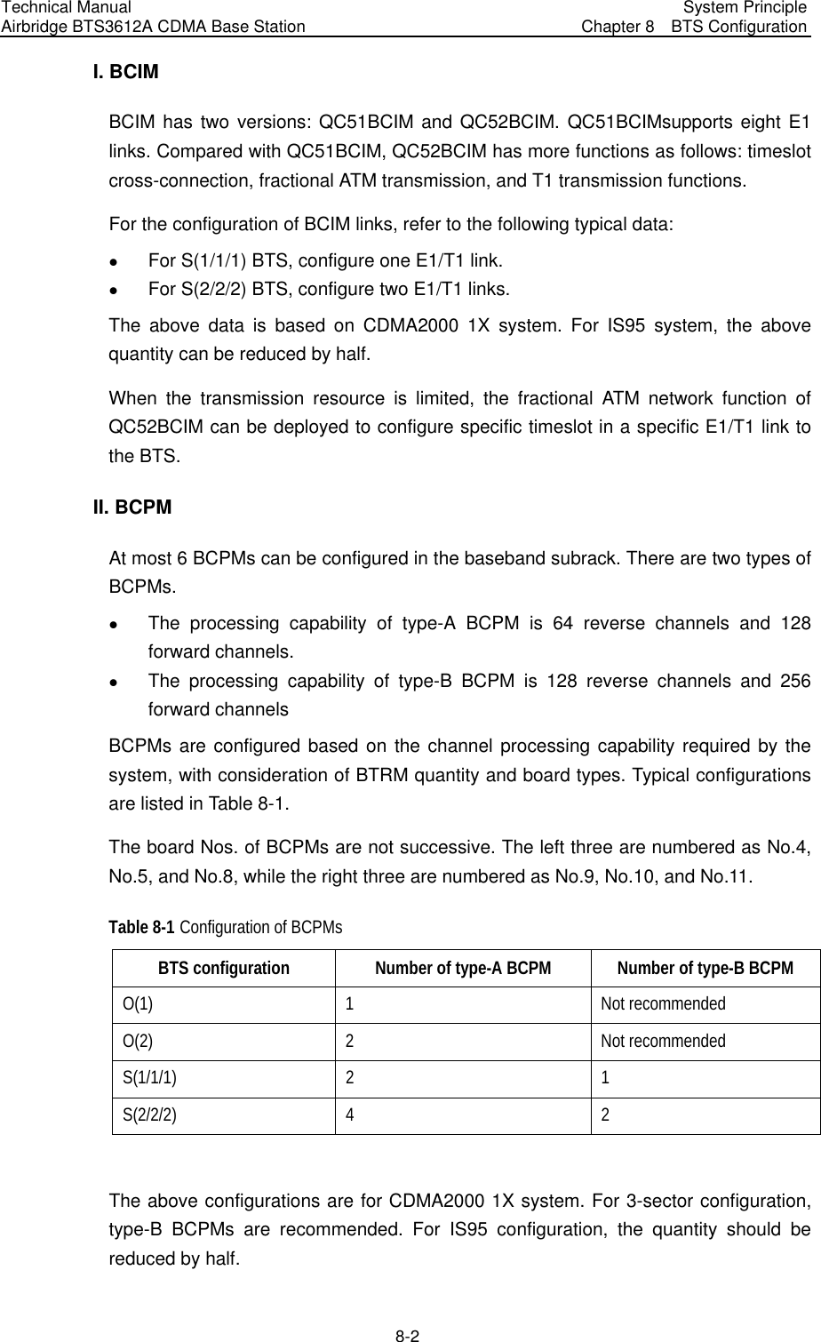
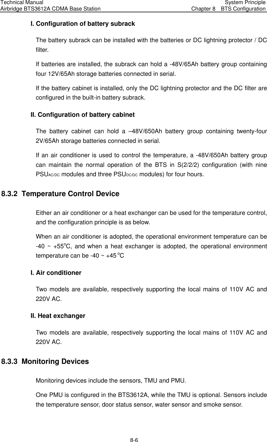
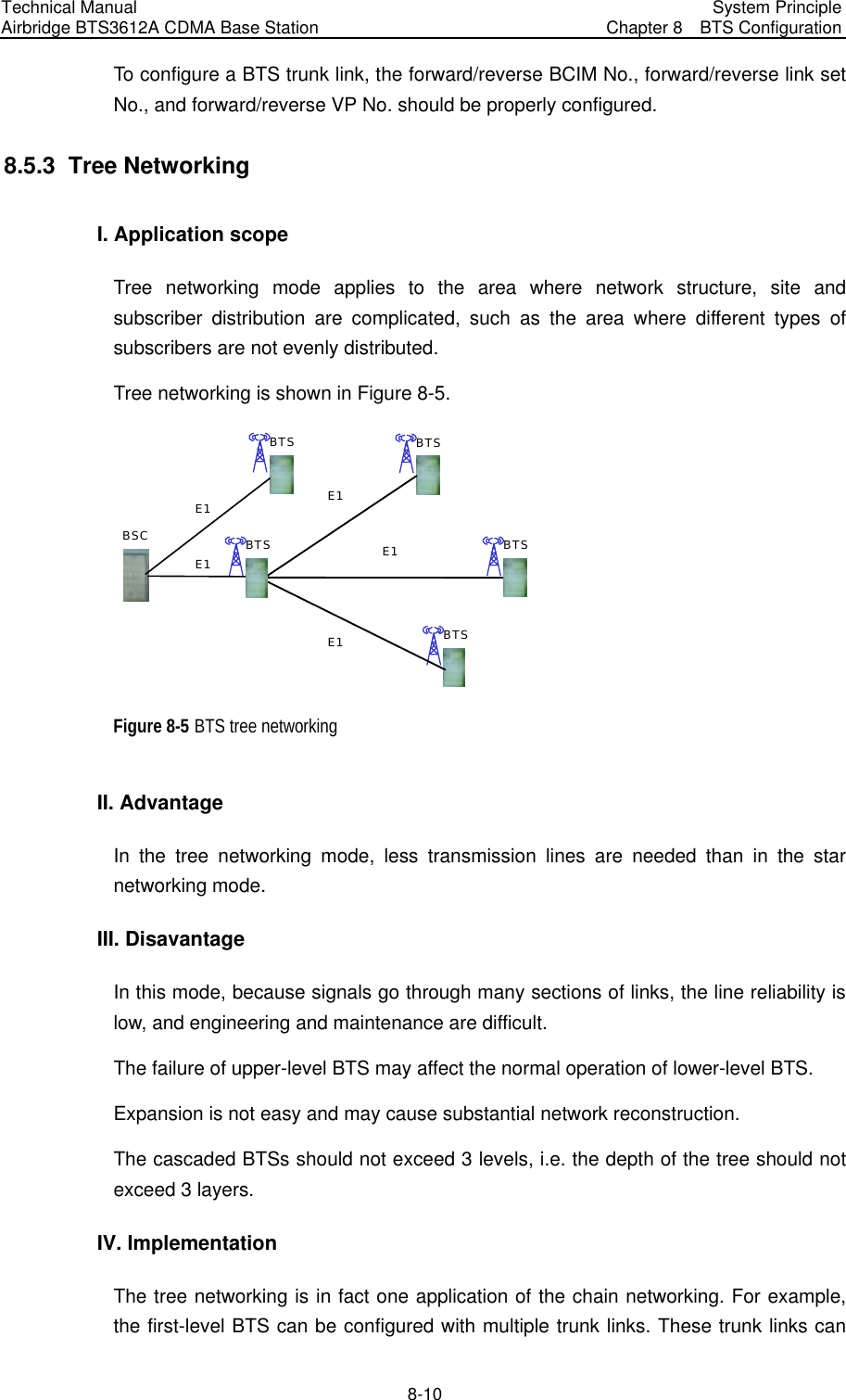
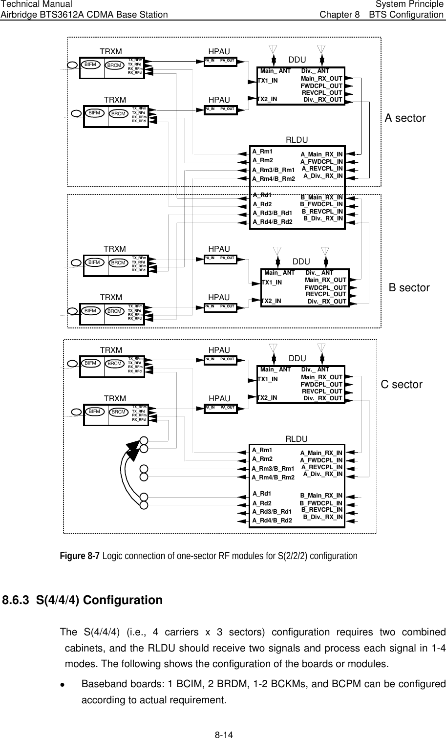
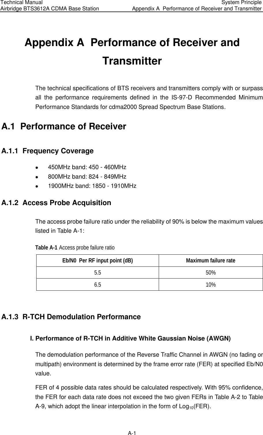
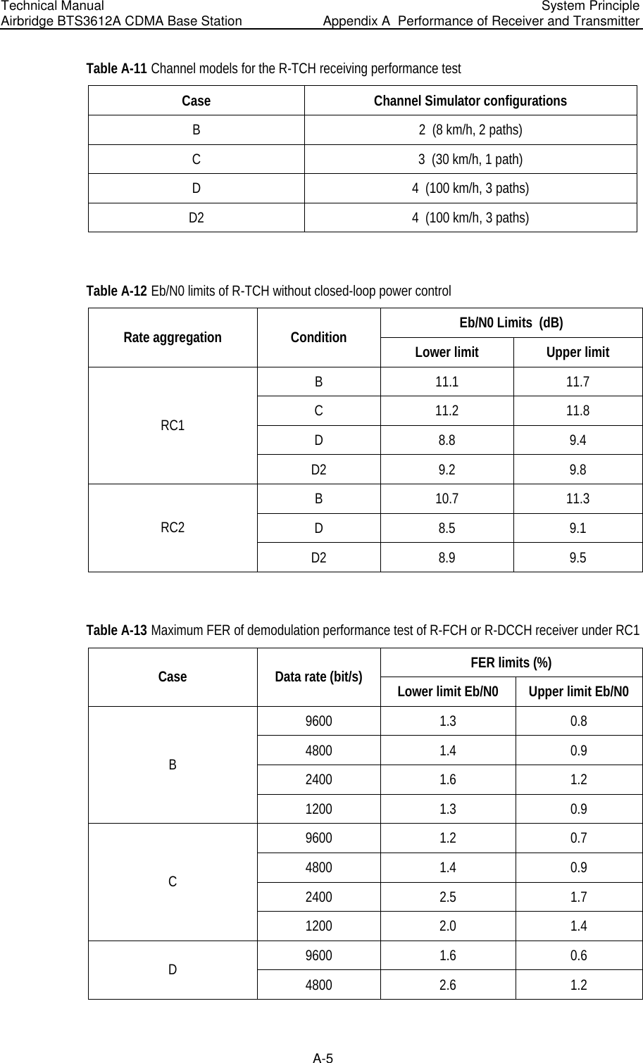
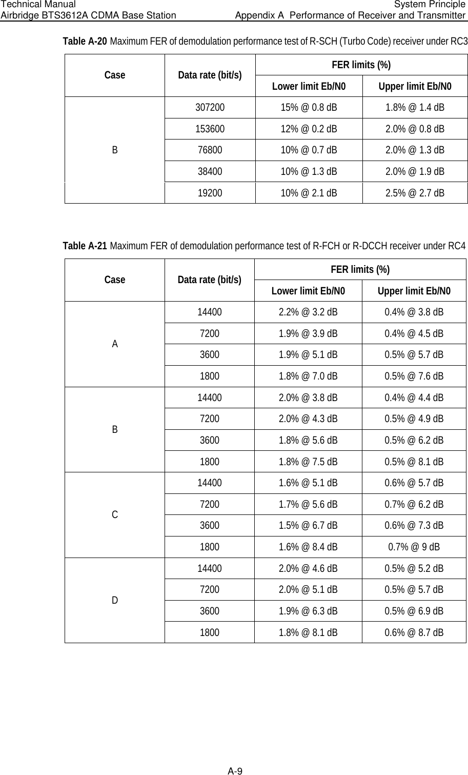
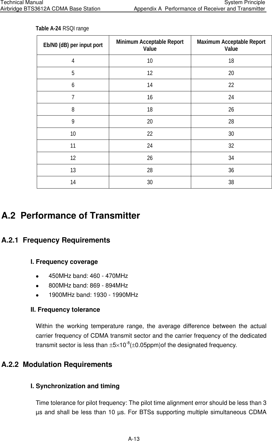
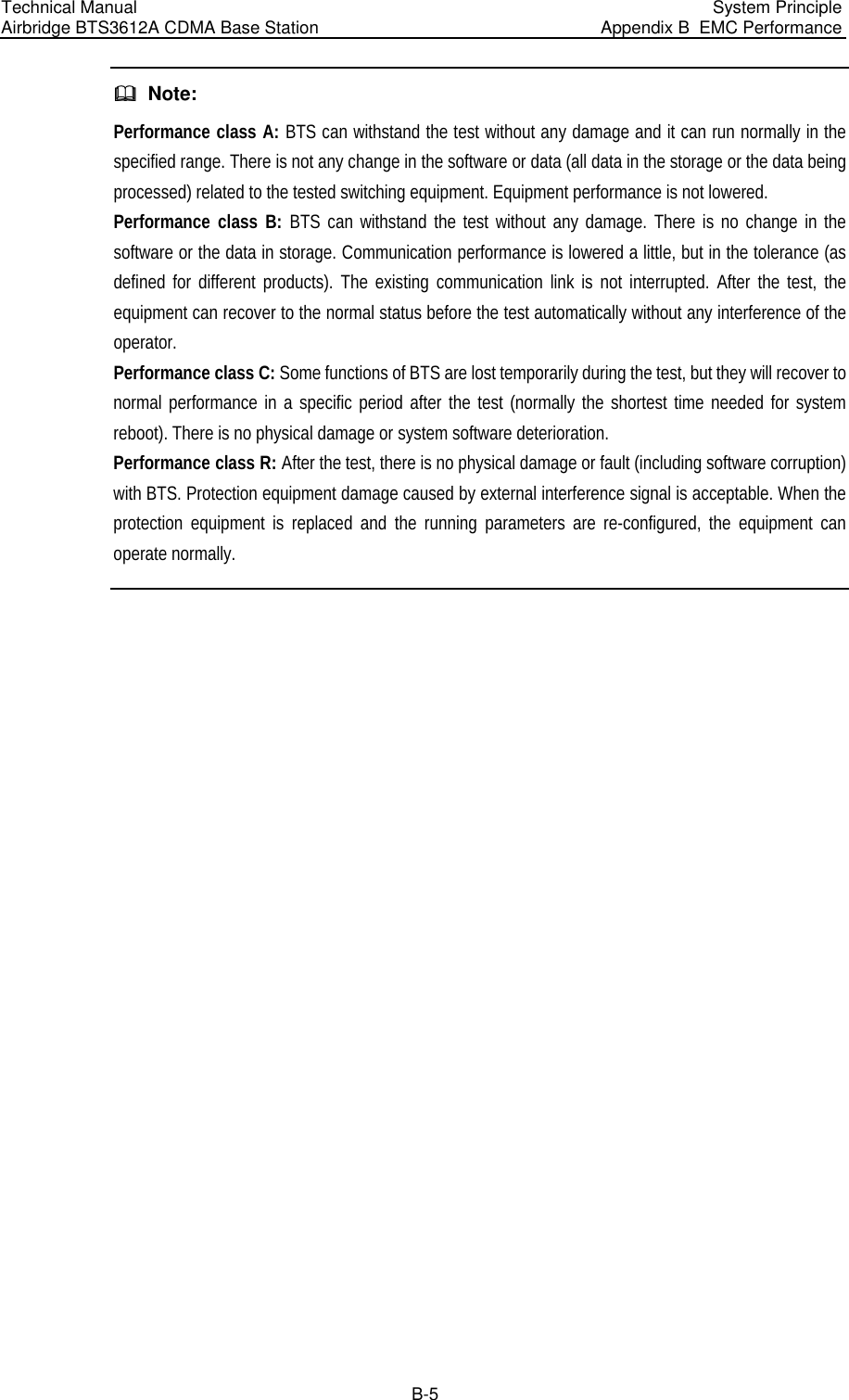
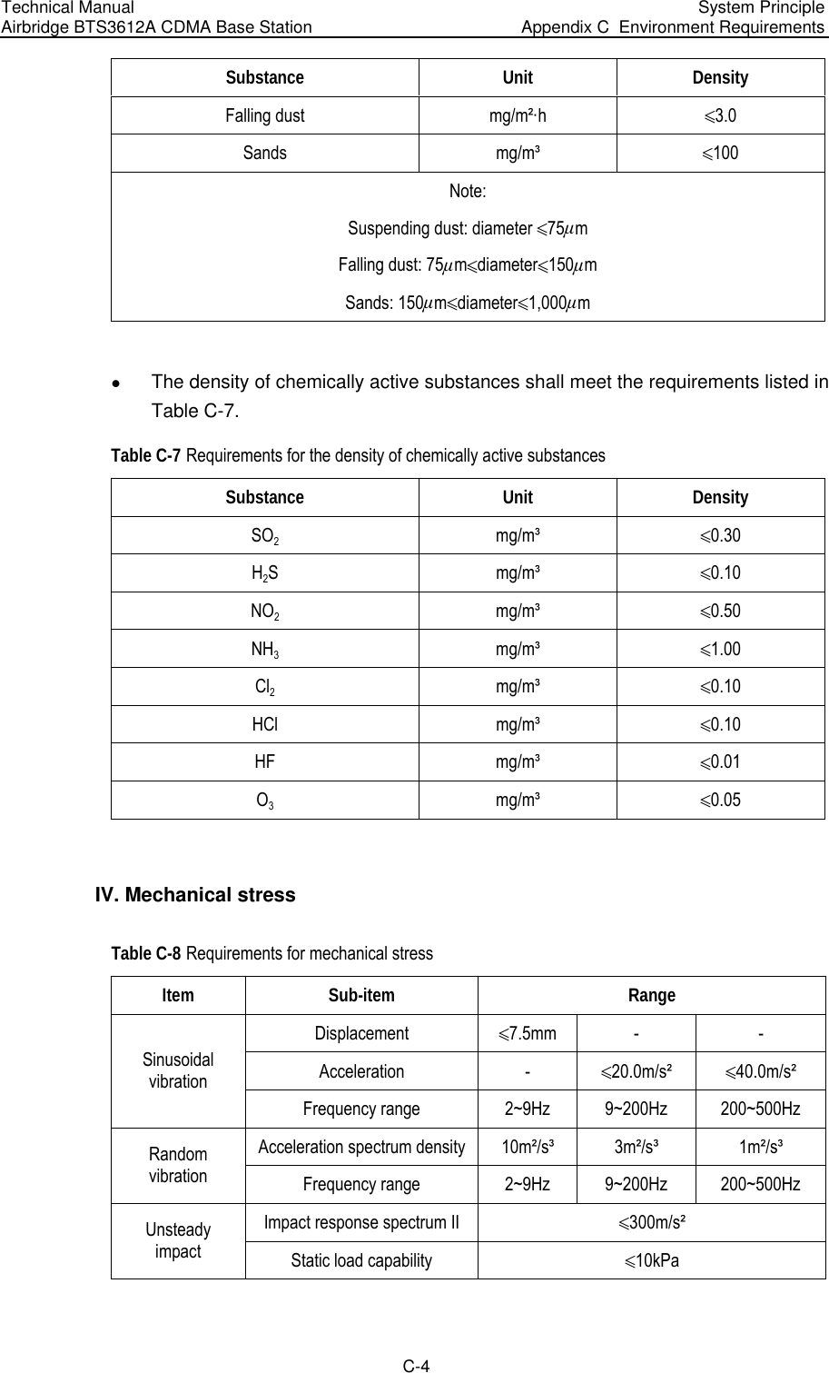
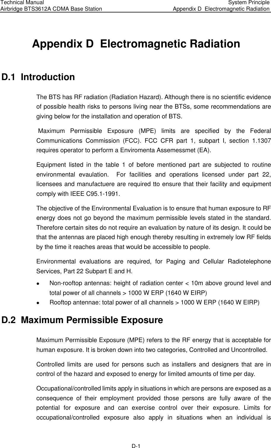
![Technical Manual Airbridge BTS3612A CDMA Base Station System Principle Appendix B EMC Performance B-2 B.2 EMS Performance I. RF EM field immunity (80~1000MHz) RF EM field immunity indices are listed in Table B-3. Table B-3 RF EM field immunity indices Port Level Performance class Whole cabinet 3V/m A Note: Test method complies with IEC1000-4-3 [9]. II. Voltage dips and short interruptions immunity Among all test items of EMS, the requirement for continuous interference immunity is class A and the requirement for transient interference immunity is class B. Requirements for voltage dips and short interruptions is shown in Table B-4. Table B-4 Voltage dips and short interruptions indices Port Test level Performance class Dip 30% Duration: 10ms A Dip: 60% Duration: 100ms With backup power: A With no backup power: The communication link need not be maintained. It can be re-created and the subscriber data can be lost. AC port Dip: over95% Duration: 5000ms With backup power: A With no backup power: The communication link need not be maintained. It can be re-created and the subscriber data can be lost. Note: Test method complies with IEC61000-4-11 [13].](https://usermanual.wiki/Huawei-Technologies/BTS3612A-1900.User-Manual-Part-3/User-Guide-384040-Page-110.png)
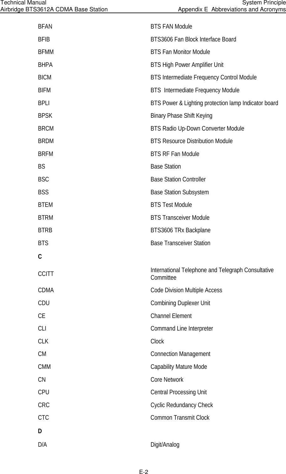
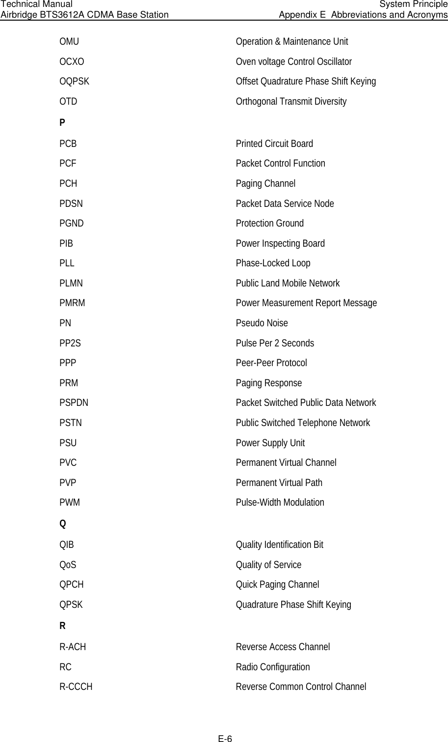
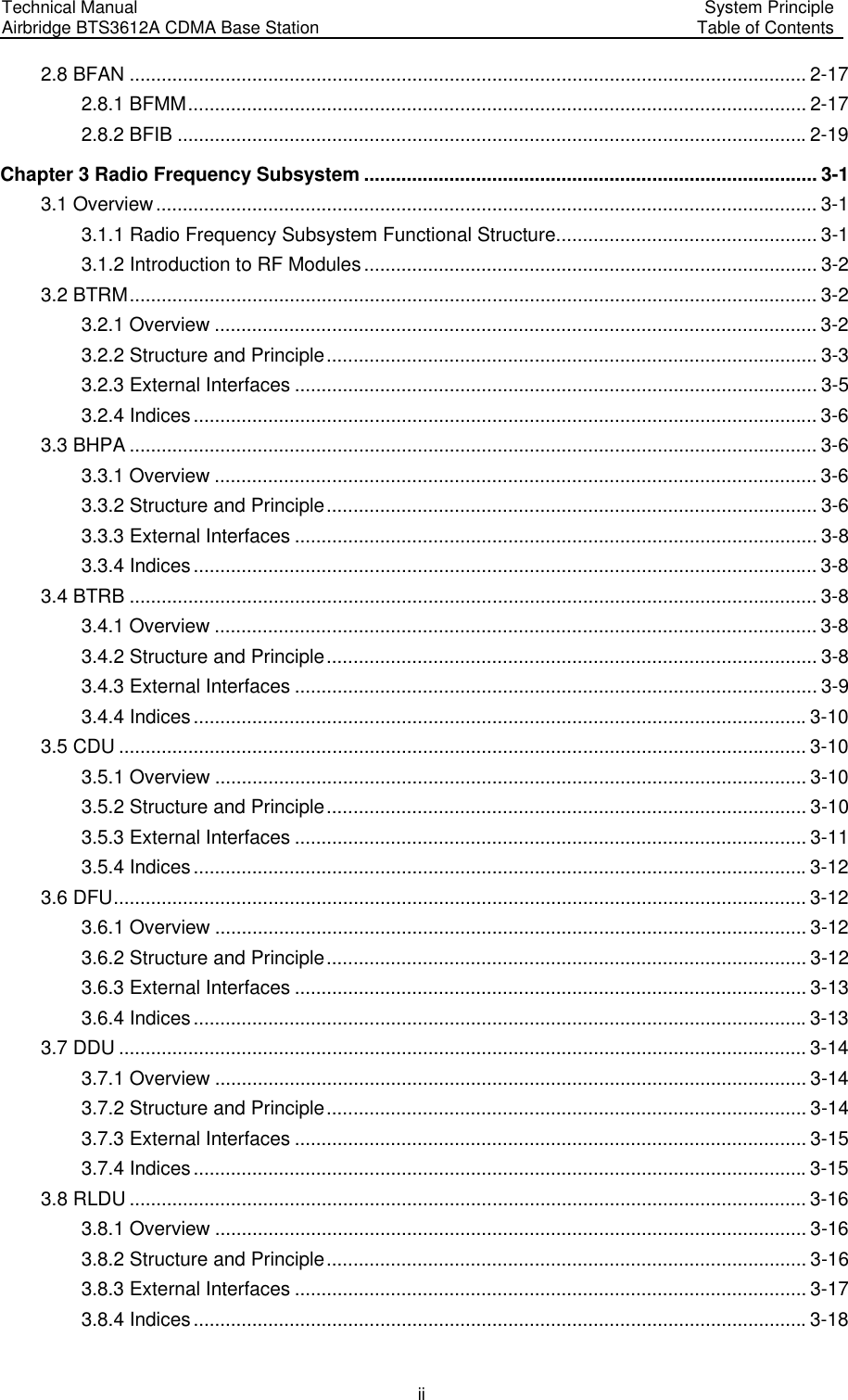
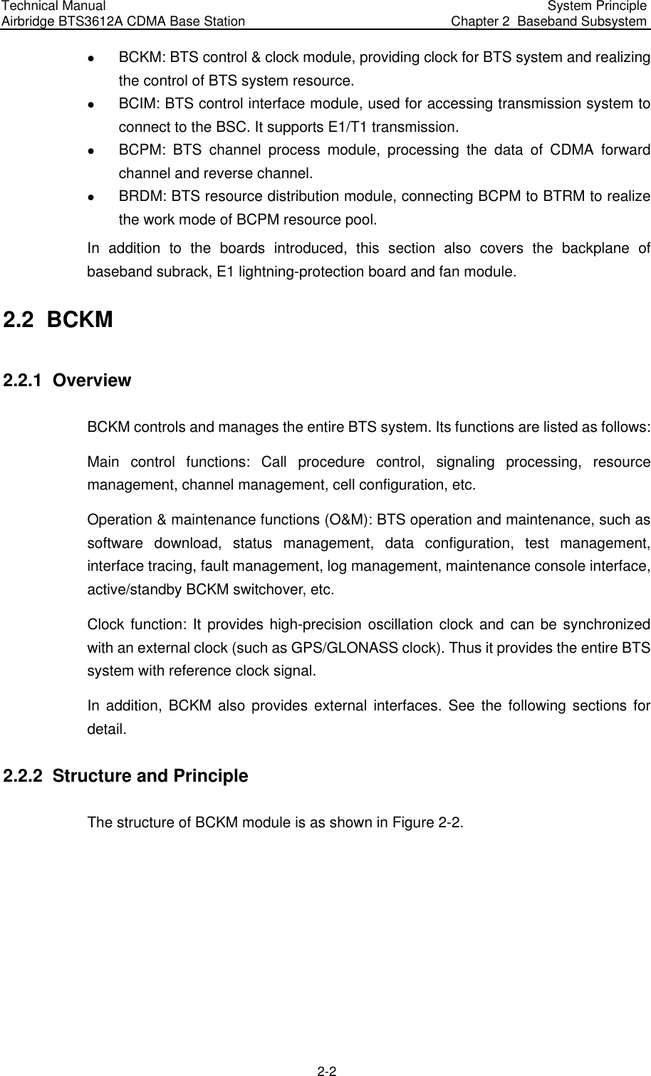
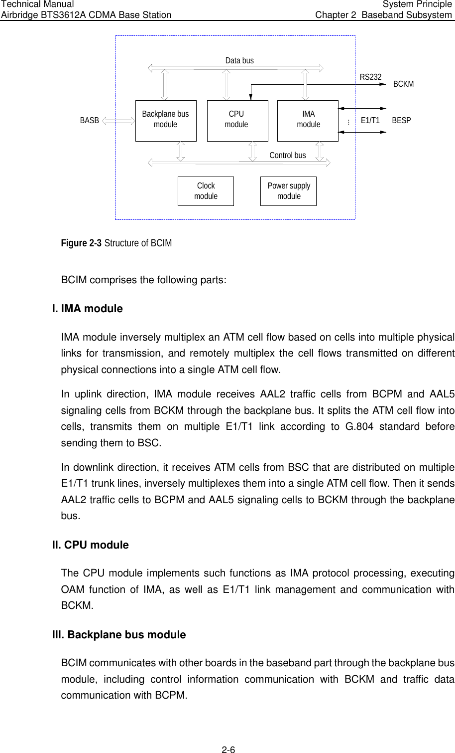
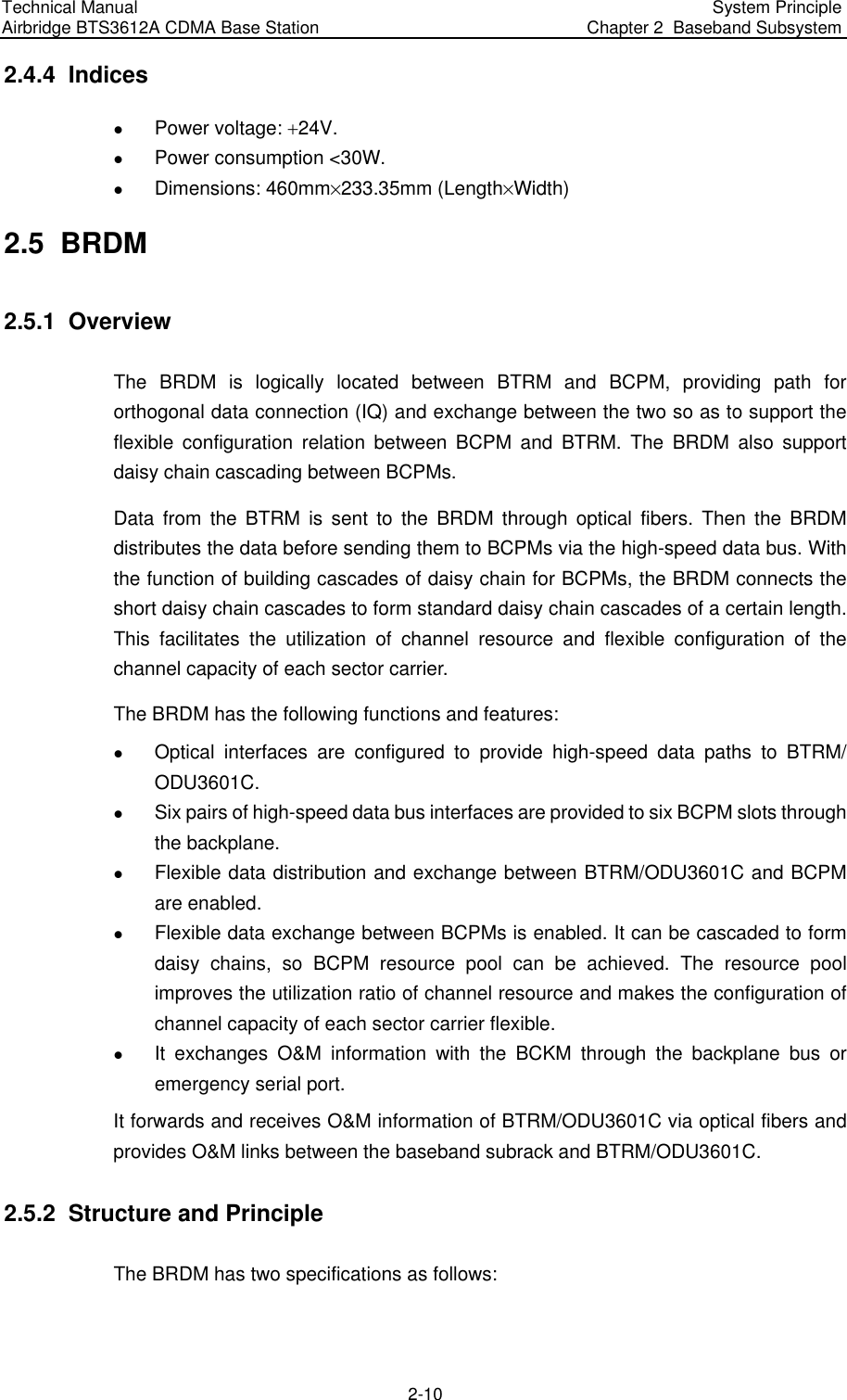
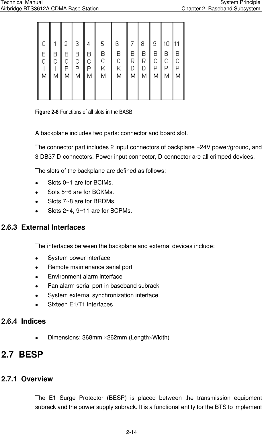
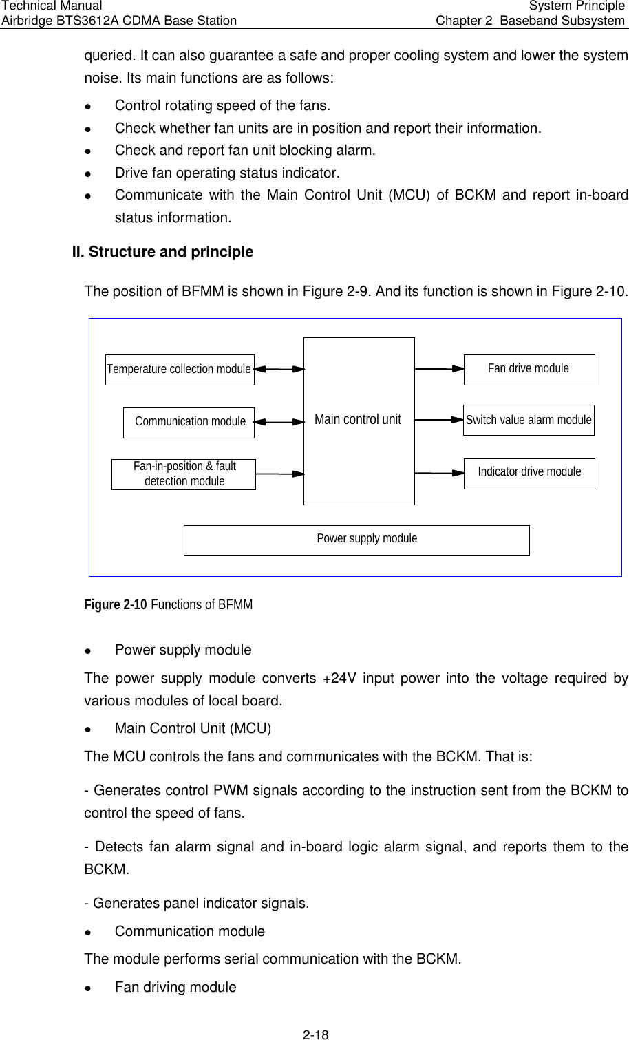
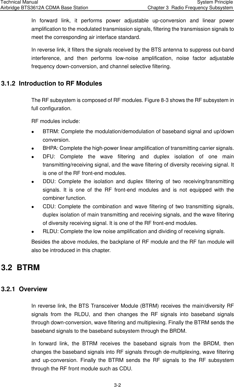
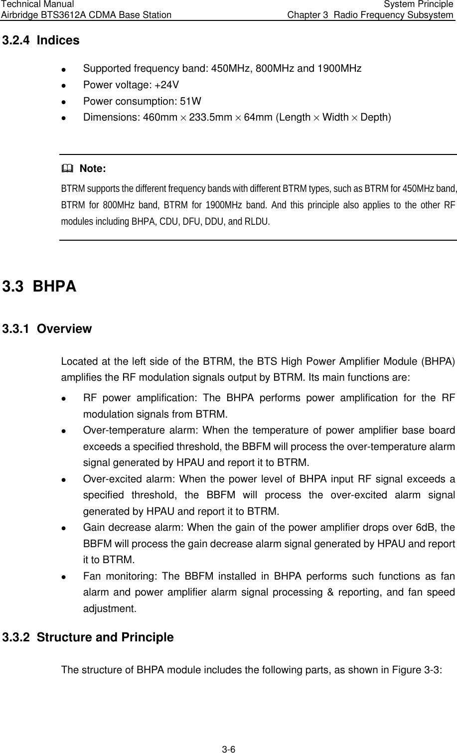
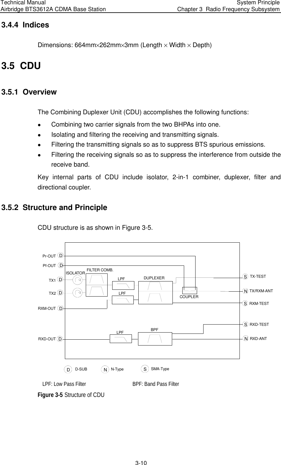
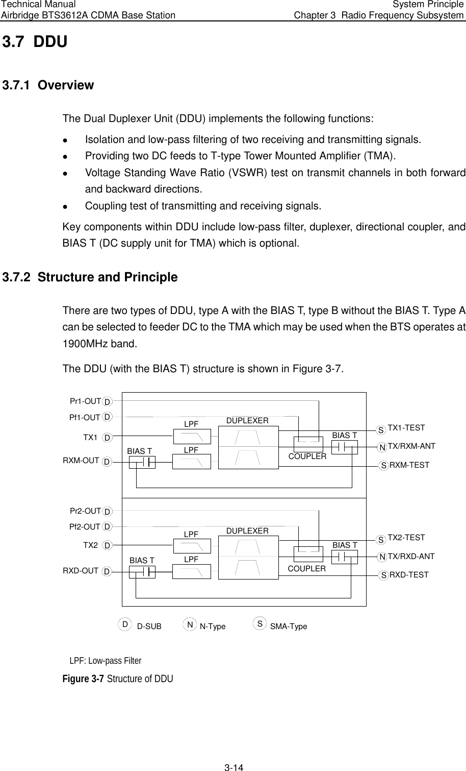
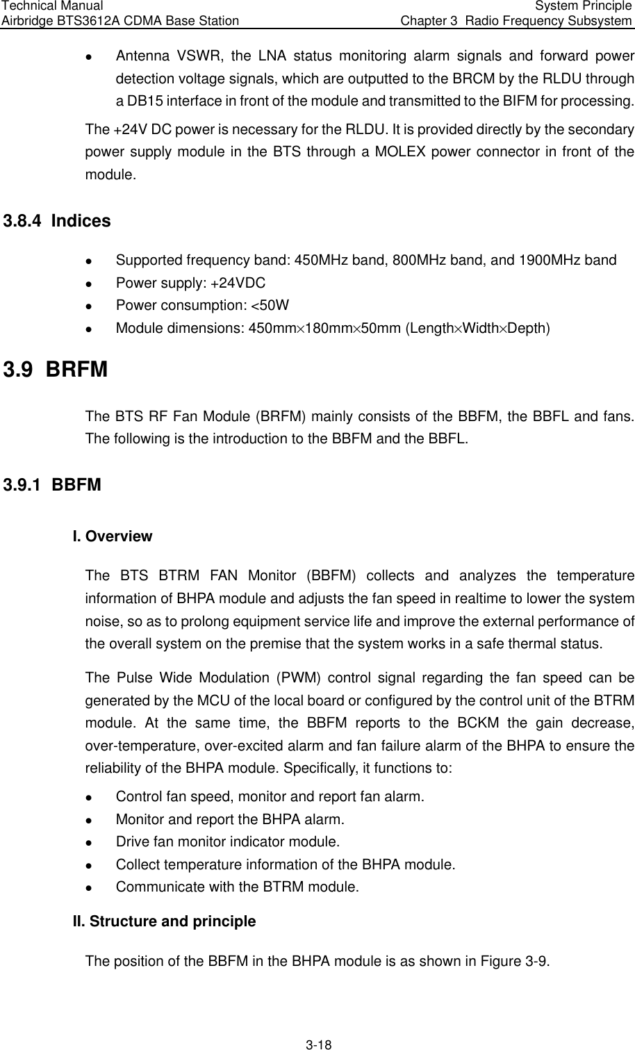
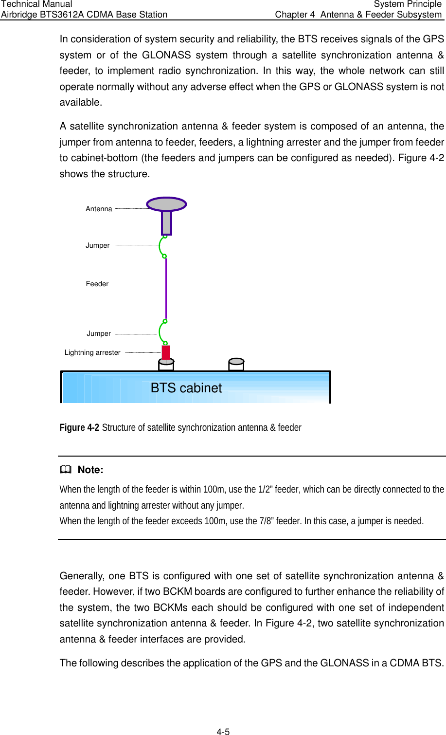
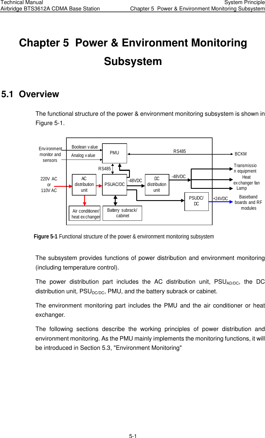
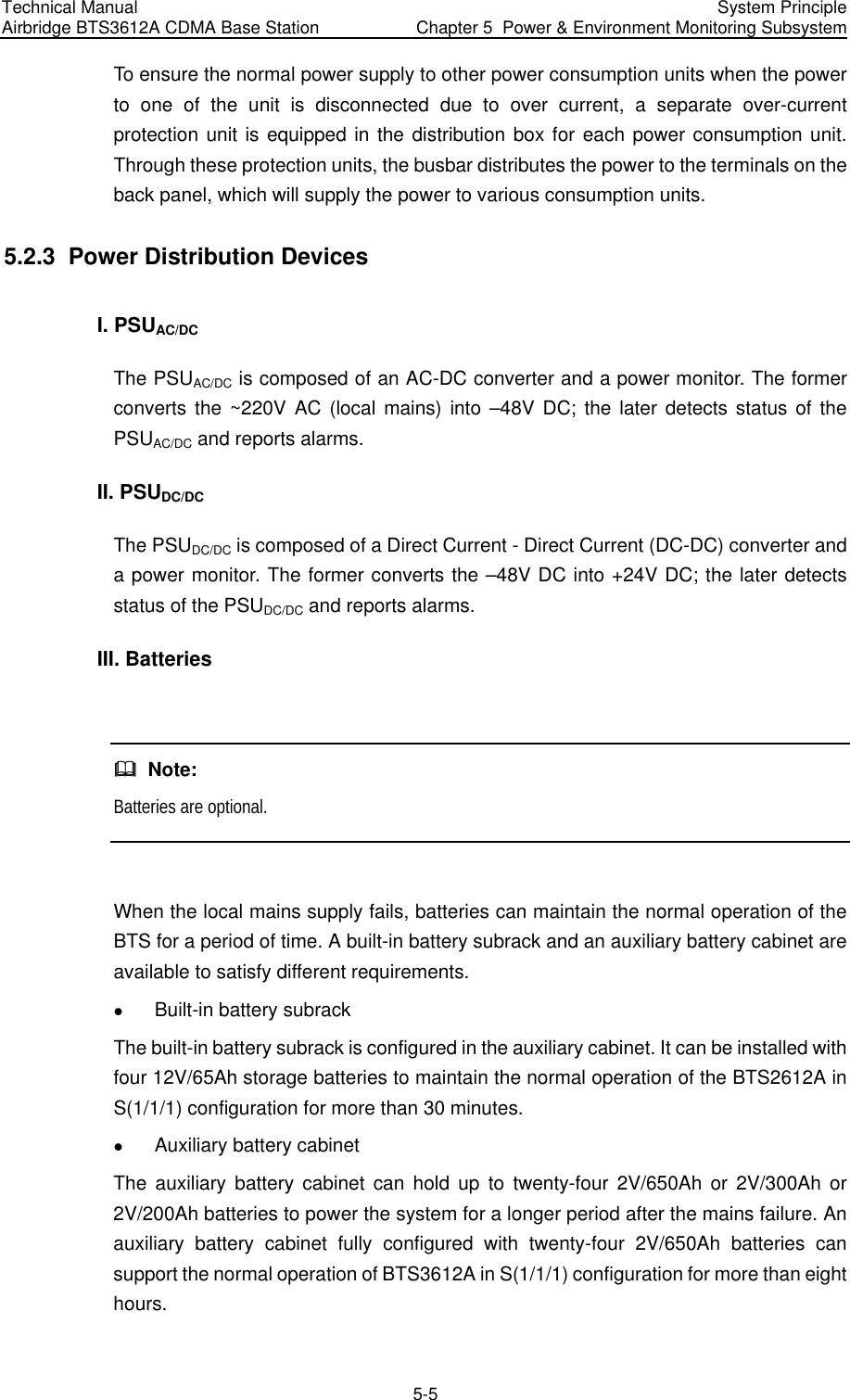
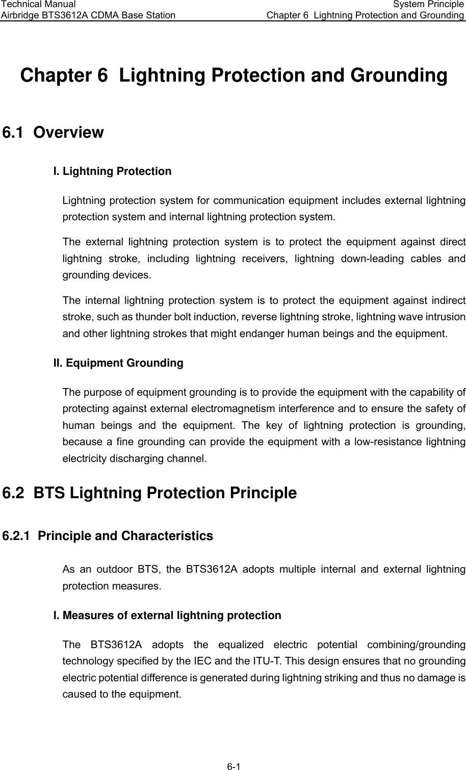
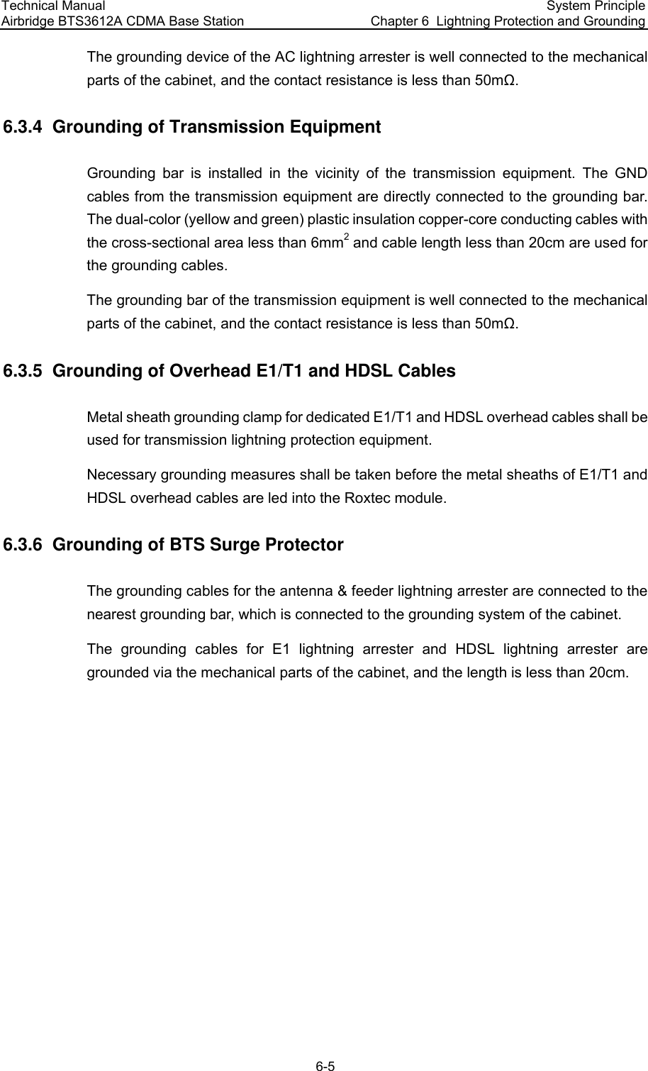
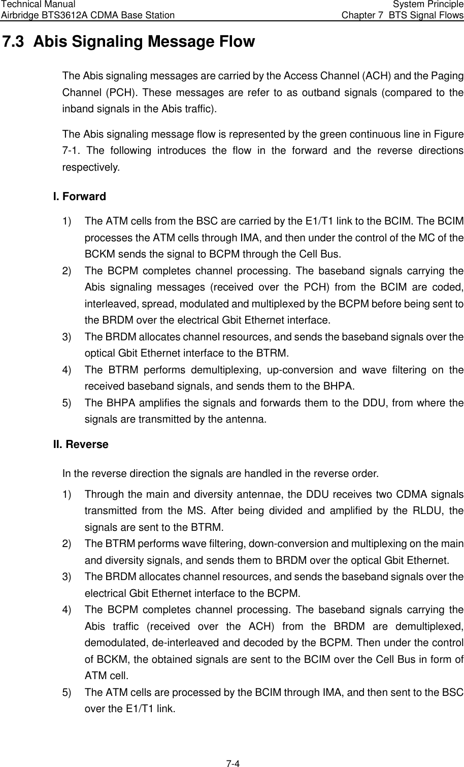
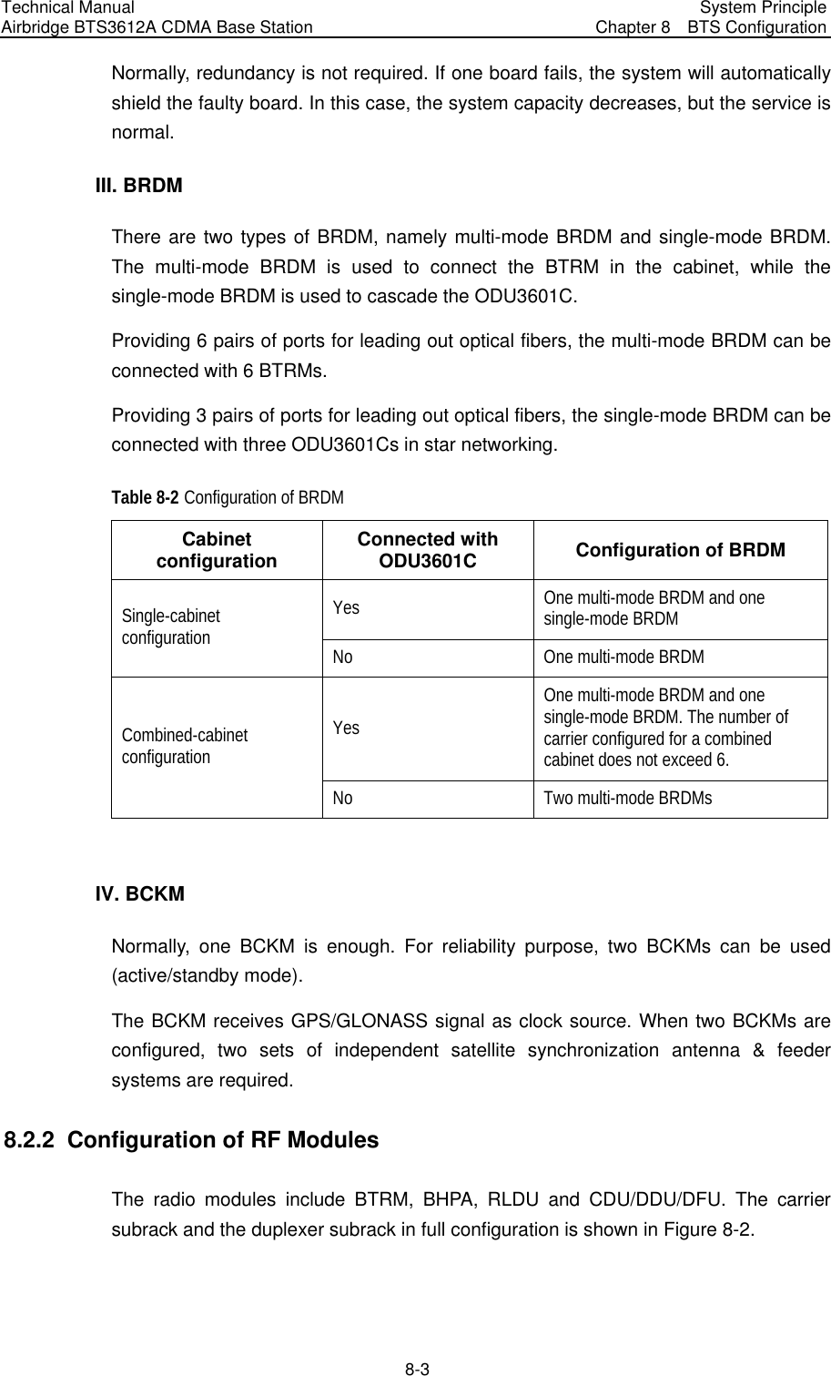
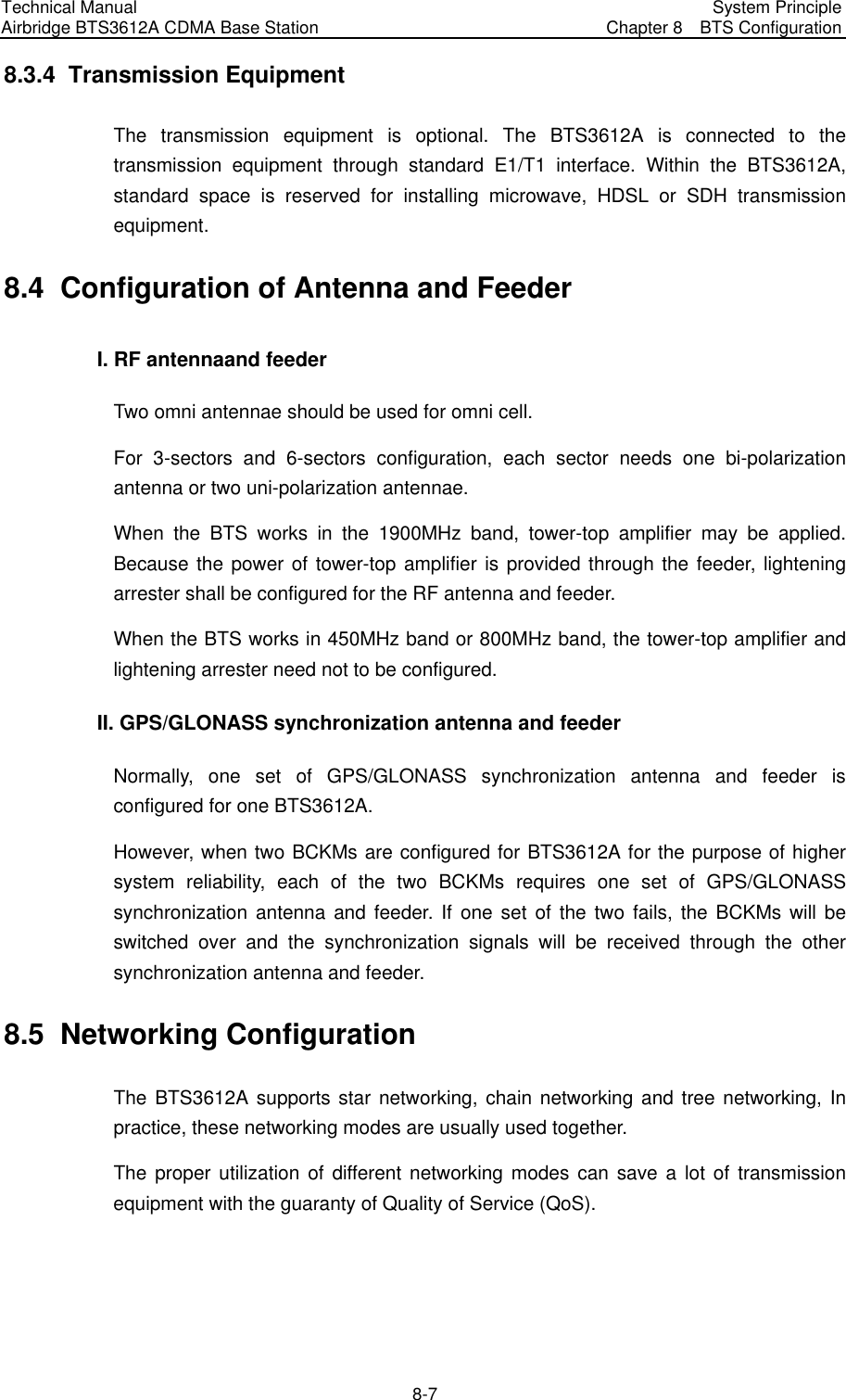
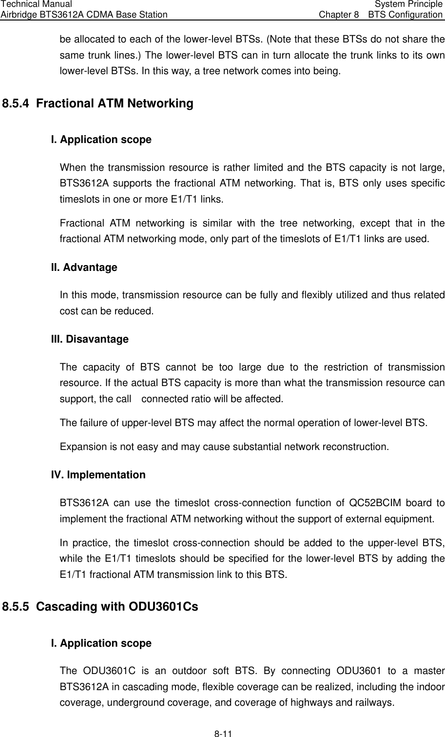
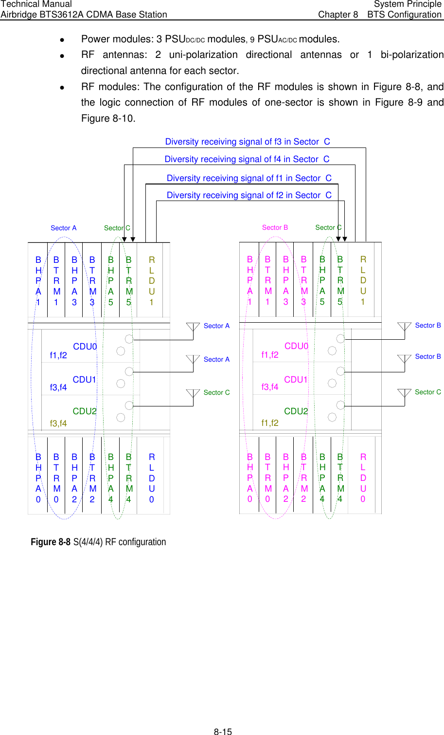
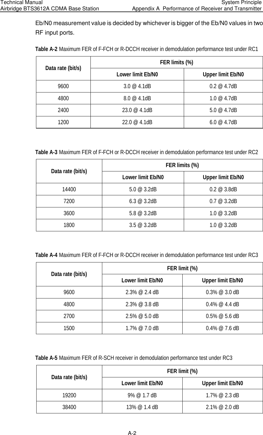
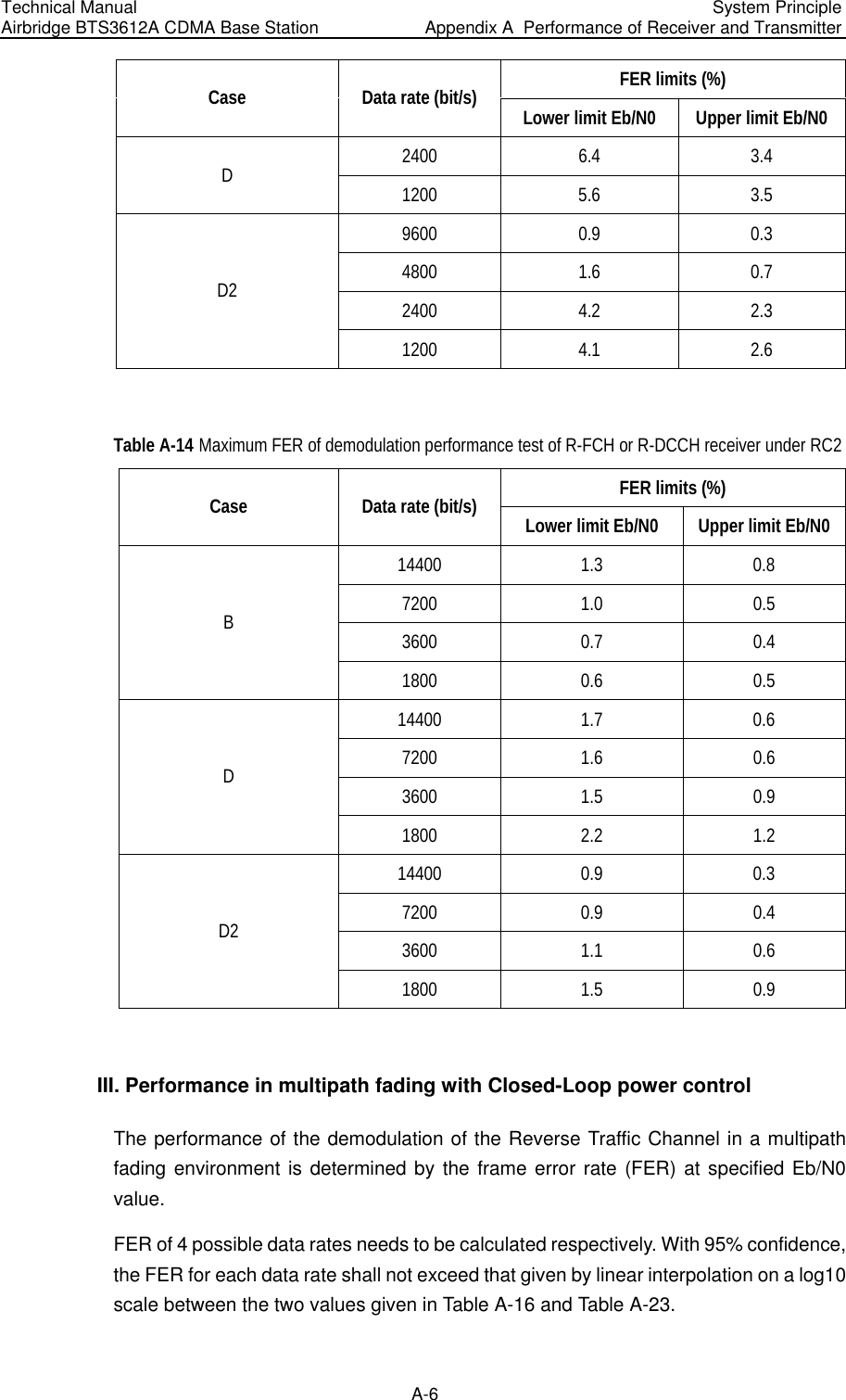
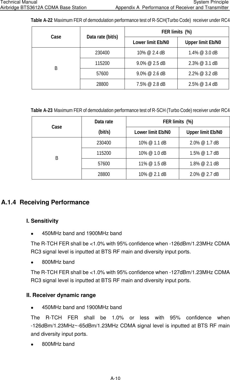
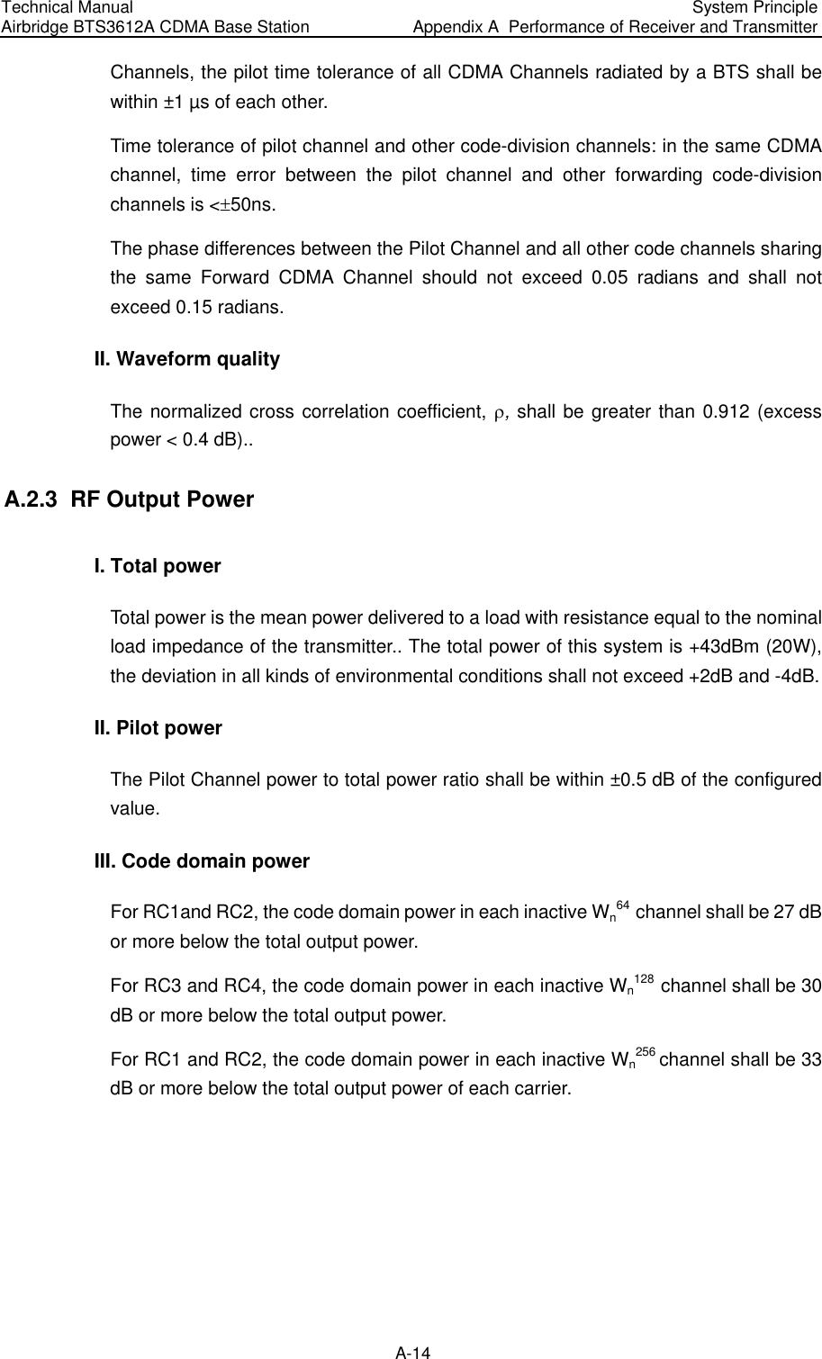
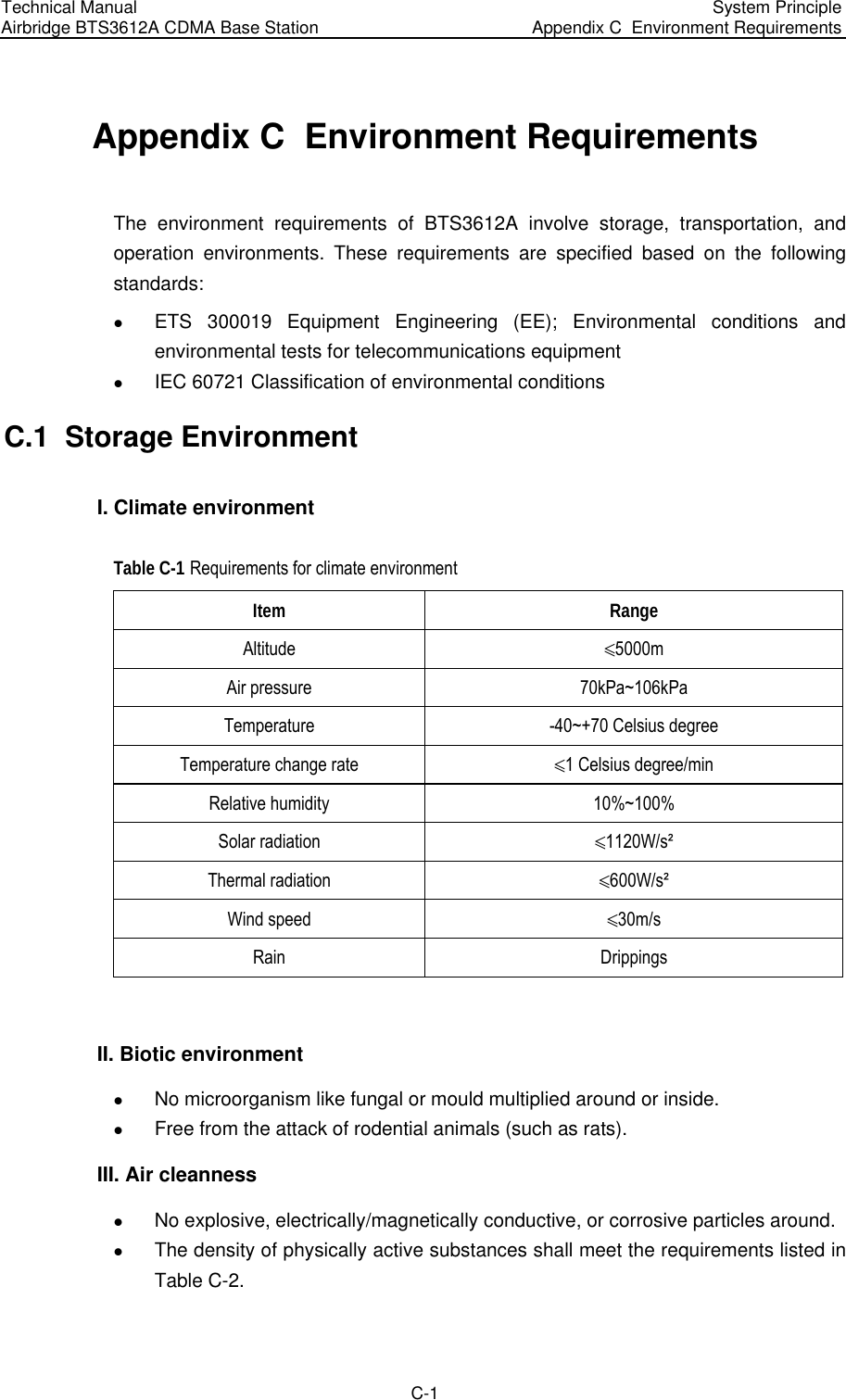
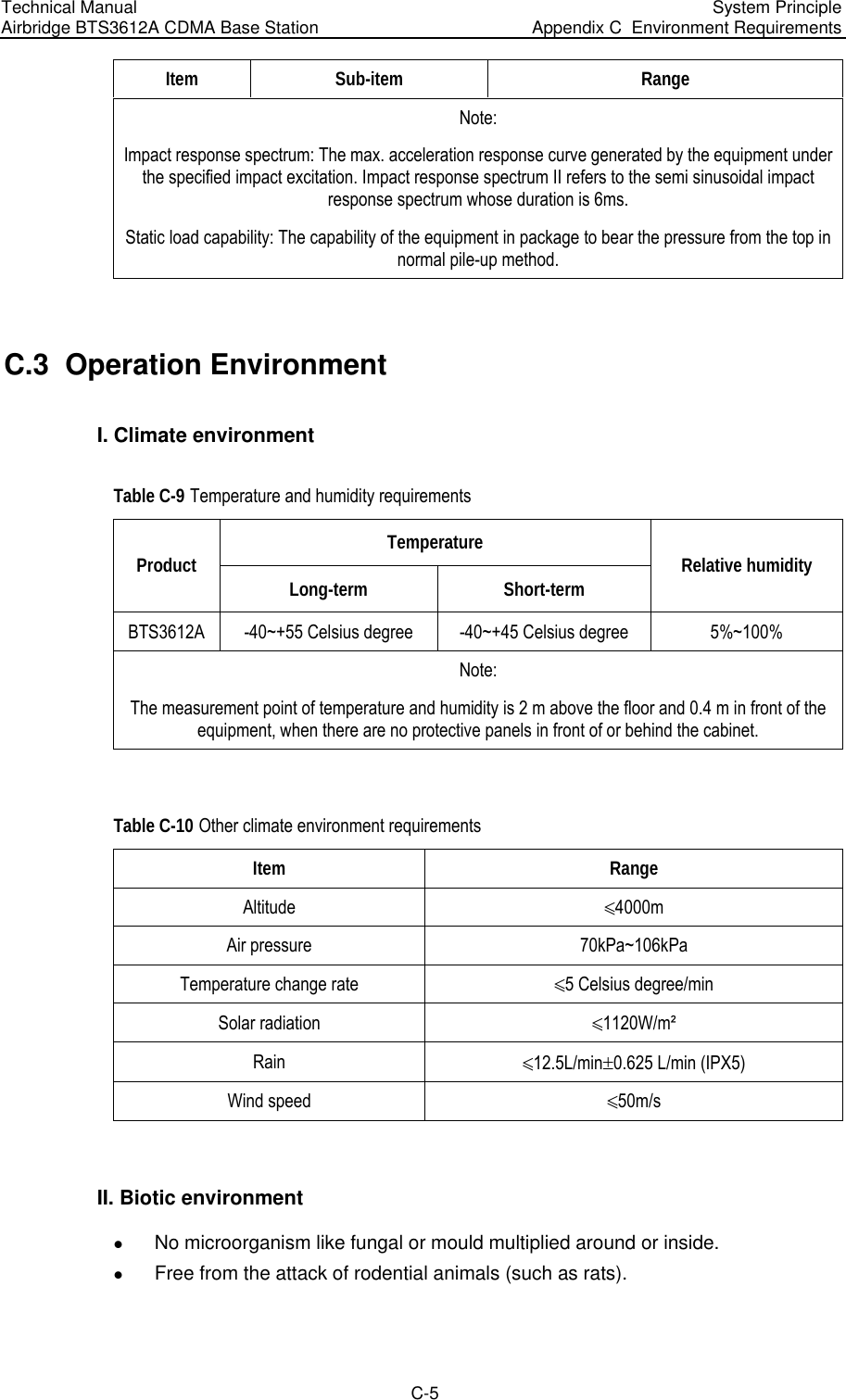
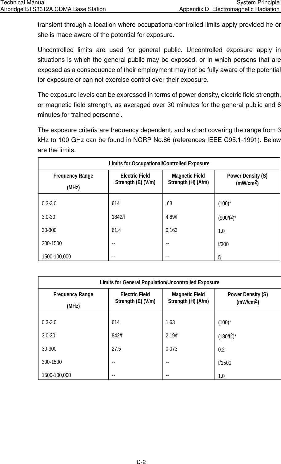
![Technical Manual Airbridge BTS3612A CDMA Base Station System Principle Appendix B EMC Performance B-3 III. Electrostatic Discharge (ESD) immunity ESD immunity indices are shown in Table B-5. Table B-5 ESD immunity indices Discharge mode Level Performance class Contact 2kV, 4kV B Air 2kV, 4kV, 8kV B Note: Test method complies with IEC 61000-4-2 [5]. In addition to the protection measures specified in the user's documents, ESD measures should be taken to all exposed surface of equipment to be tested. IV. RF induced currents In CDMA equipment, the port where a cable of more than 1 meter may be connected to, including control port, DC input/output port and the input/output port of the connection line when cabinets are combined, should satisfy the requirements for RF induced currents. The indices are shown in Table B-6. Table B-6 Induced currents indices Port Voltage level Performance class DC line port AC line port Signal line port and control line port 3V A Note: Test method complies with IEC61000-4-6 [9]. V. Surge immunity For CDMA equipment, the DC power input port, indoor signal line of more than 3 m, control line (such as E1 trunk line, serial port line) and the cable that may be led out to](https://usermanual.wiki/Huawei-Technologies/BTS3612A-1900.User-Manual-Part-3/User-Guide-384040-Page-111.png)
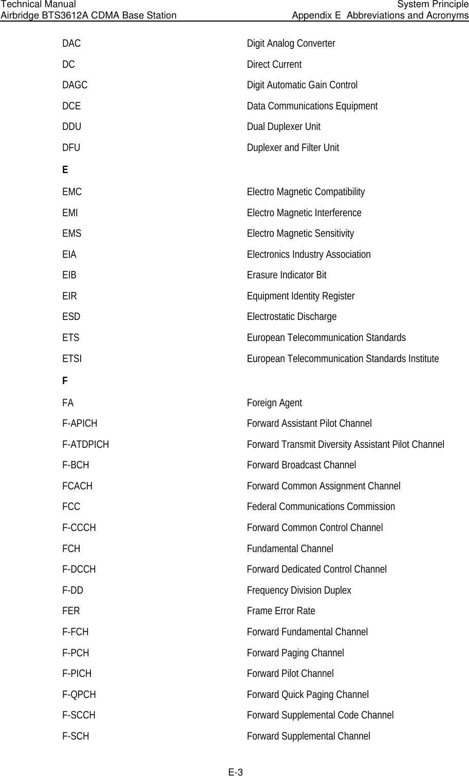
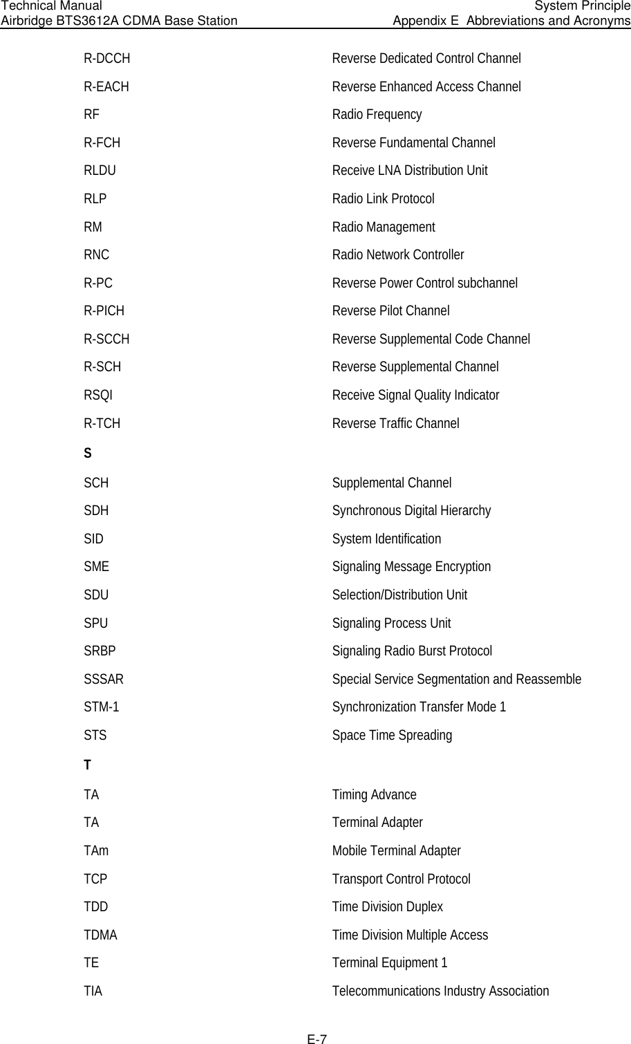
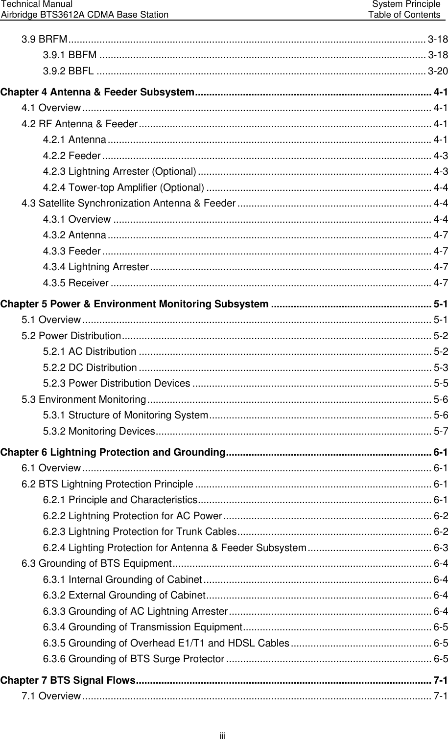
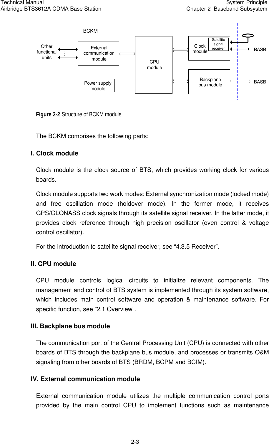
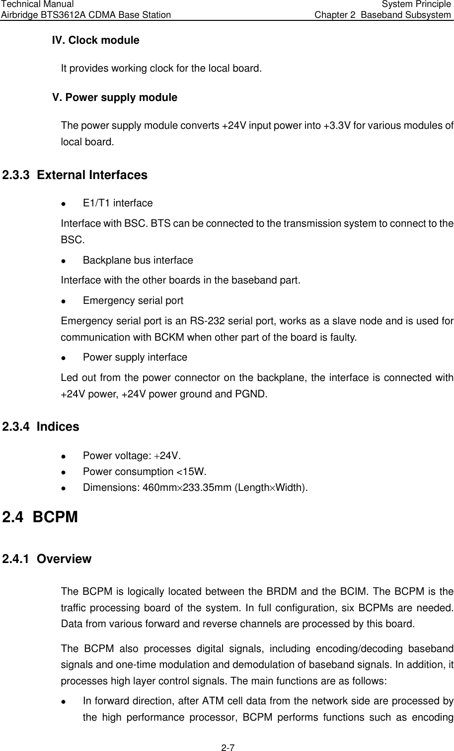
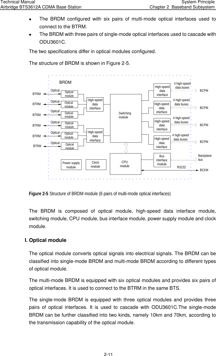
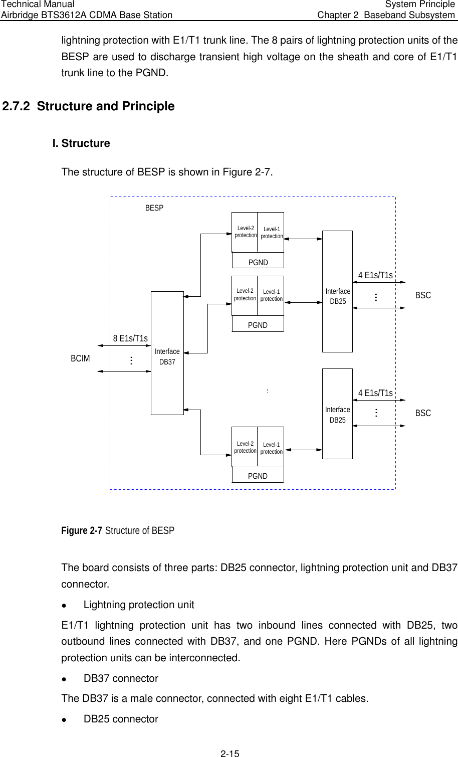
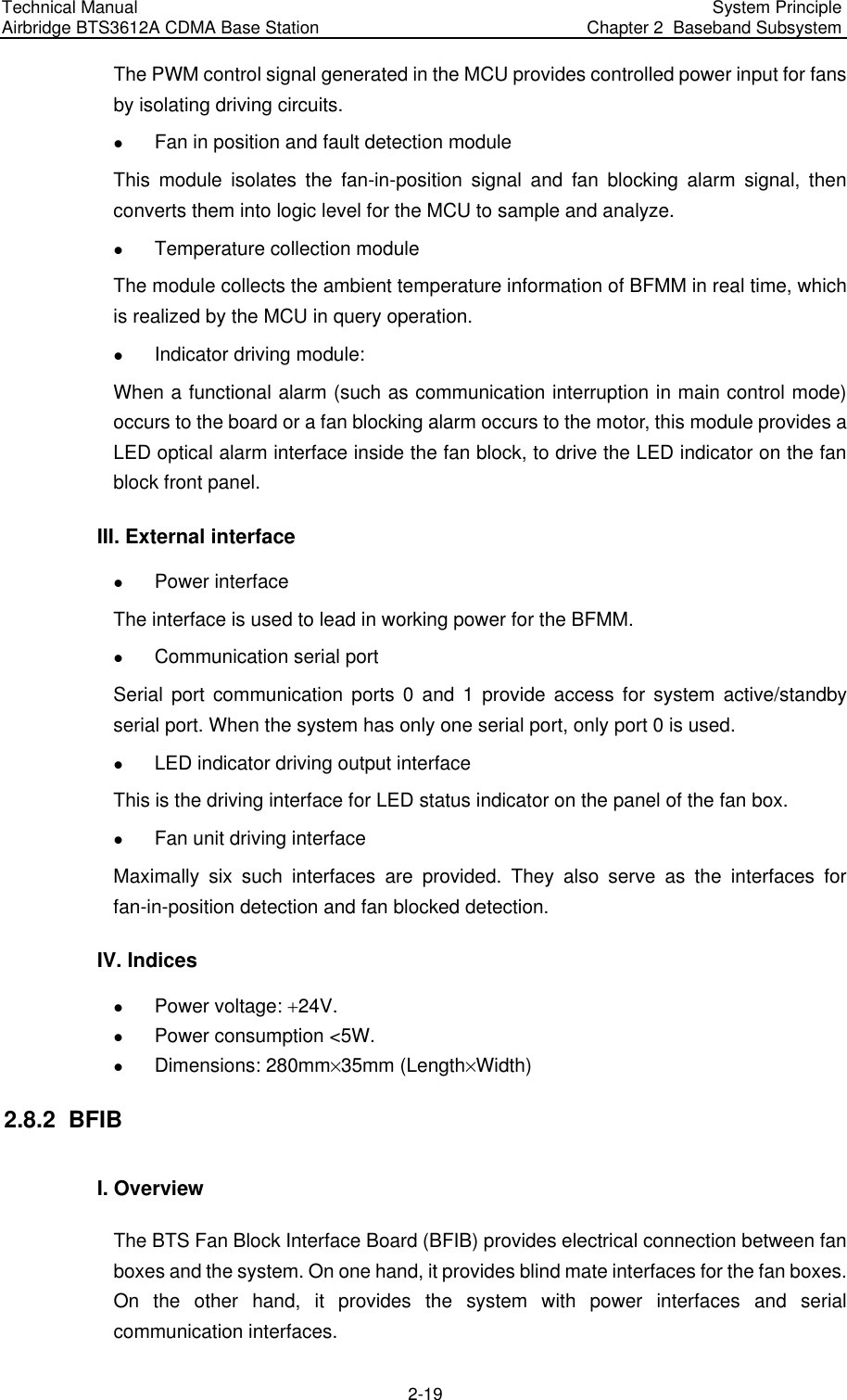
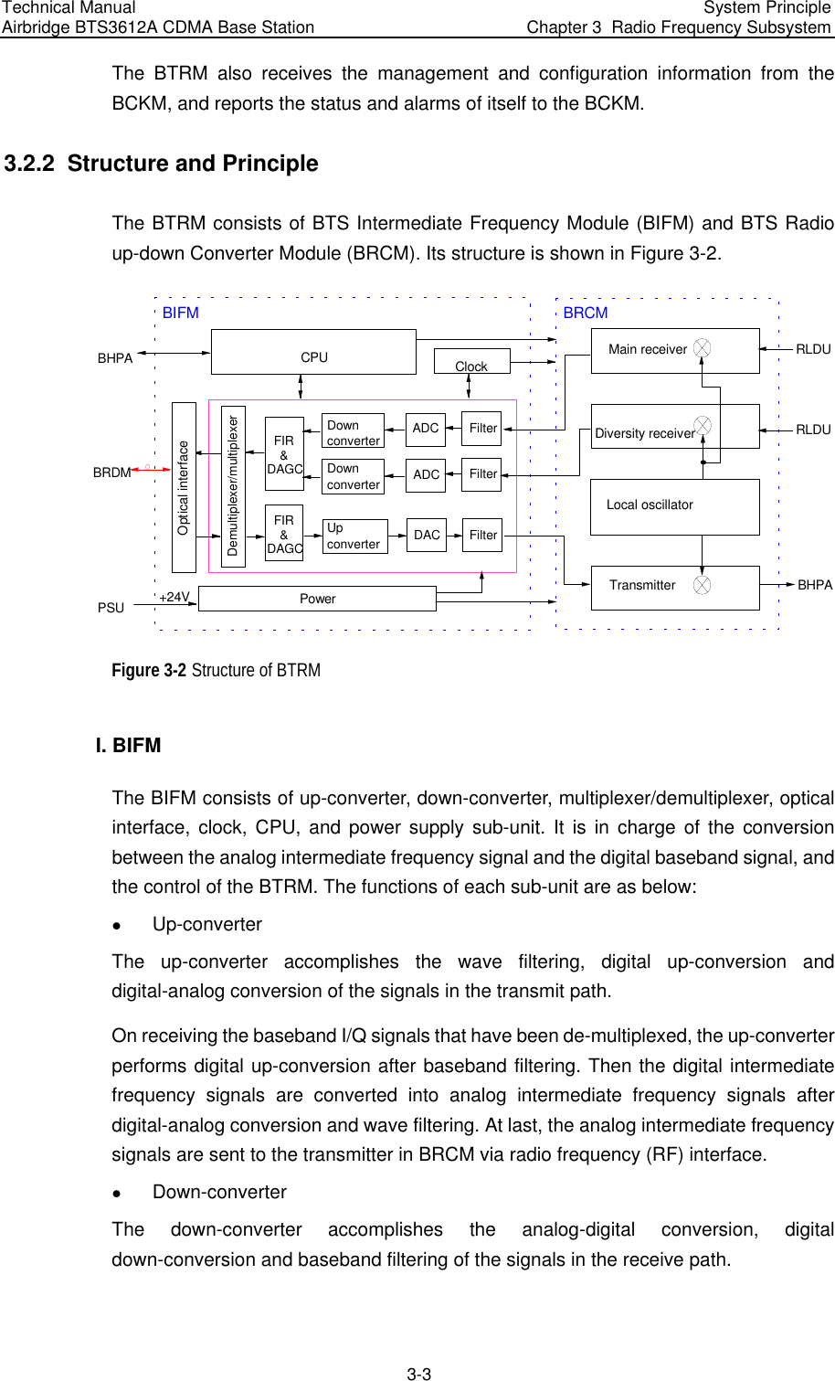
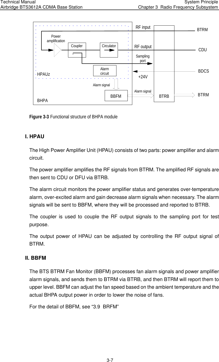
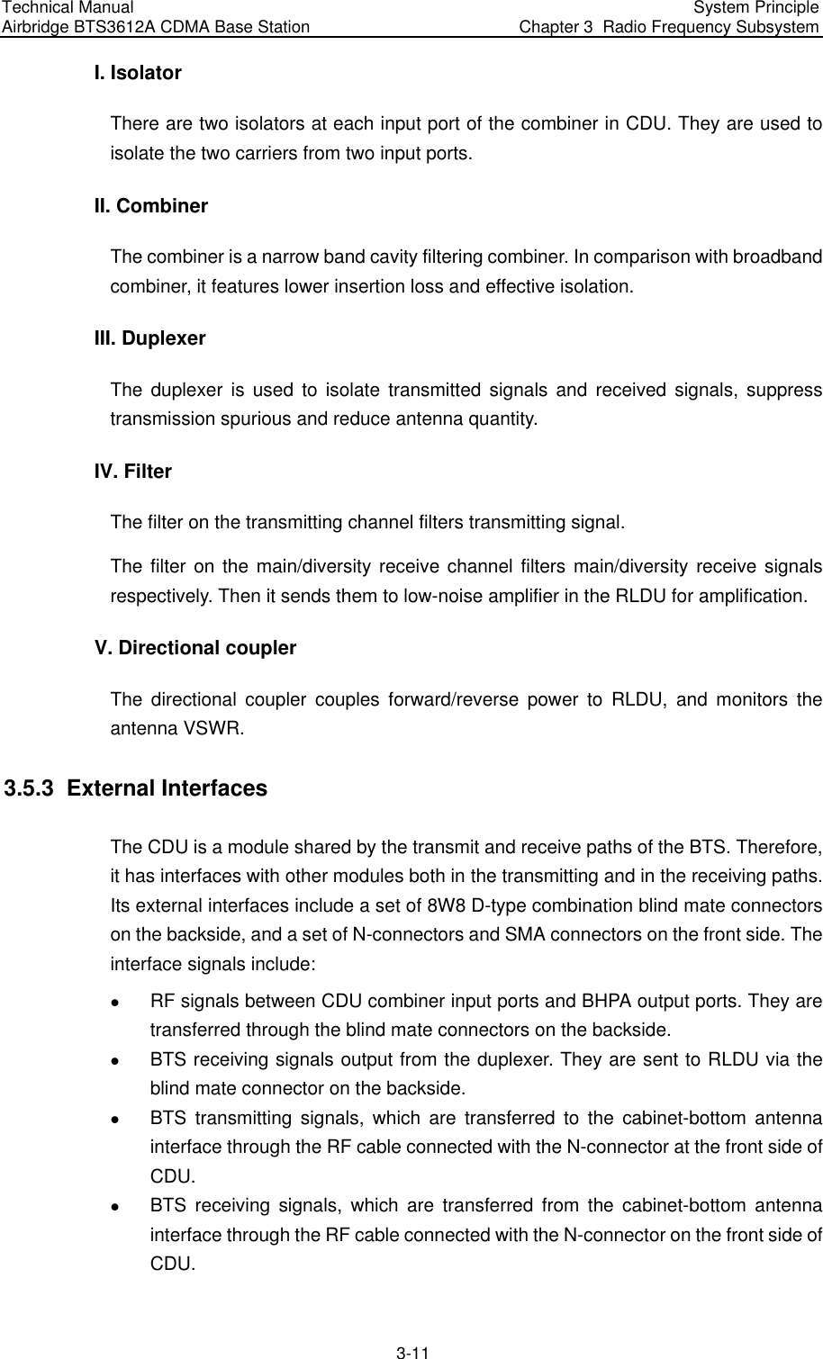
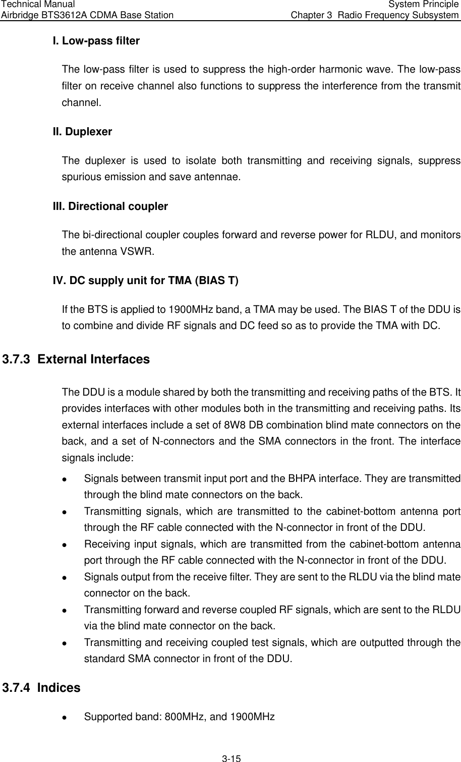
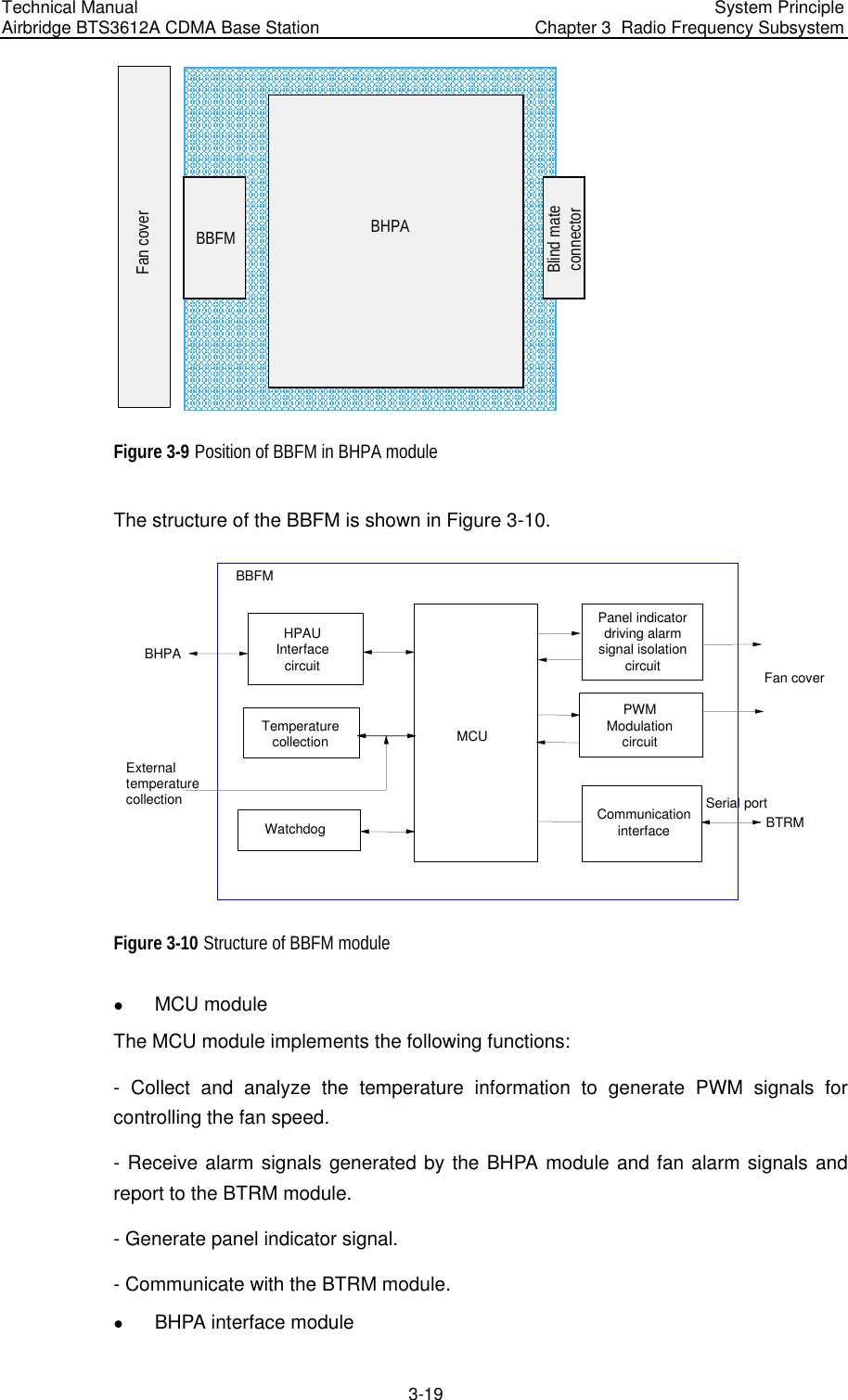
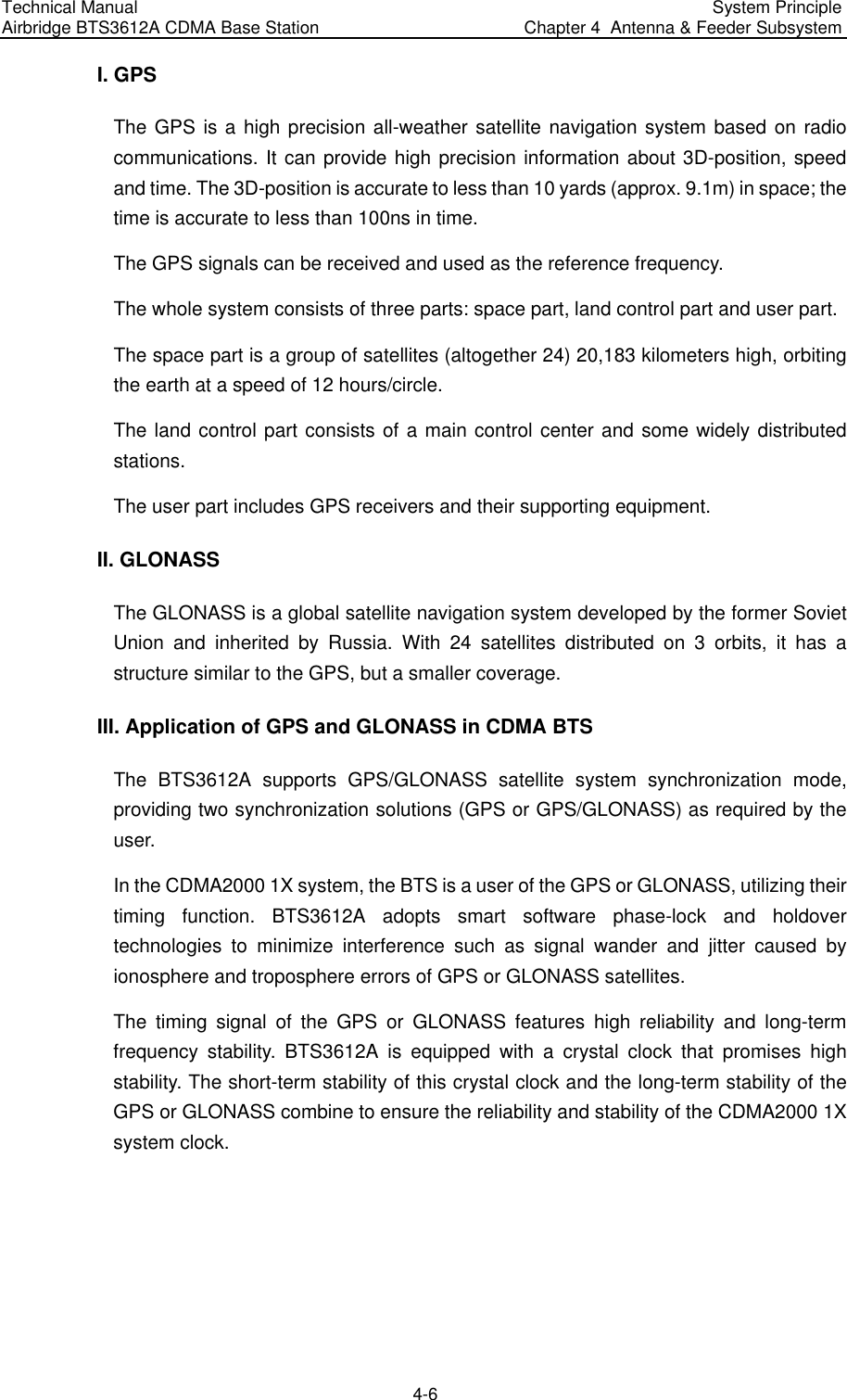
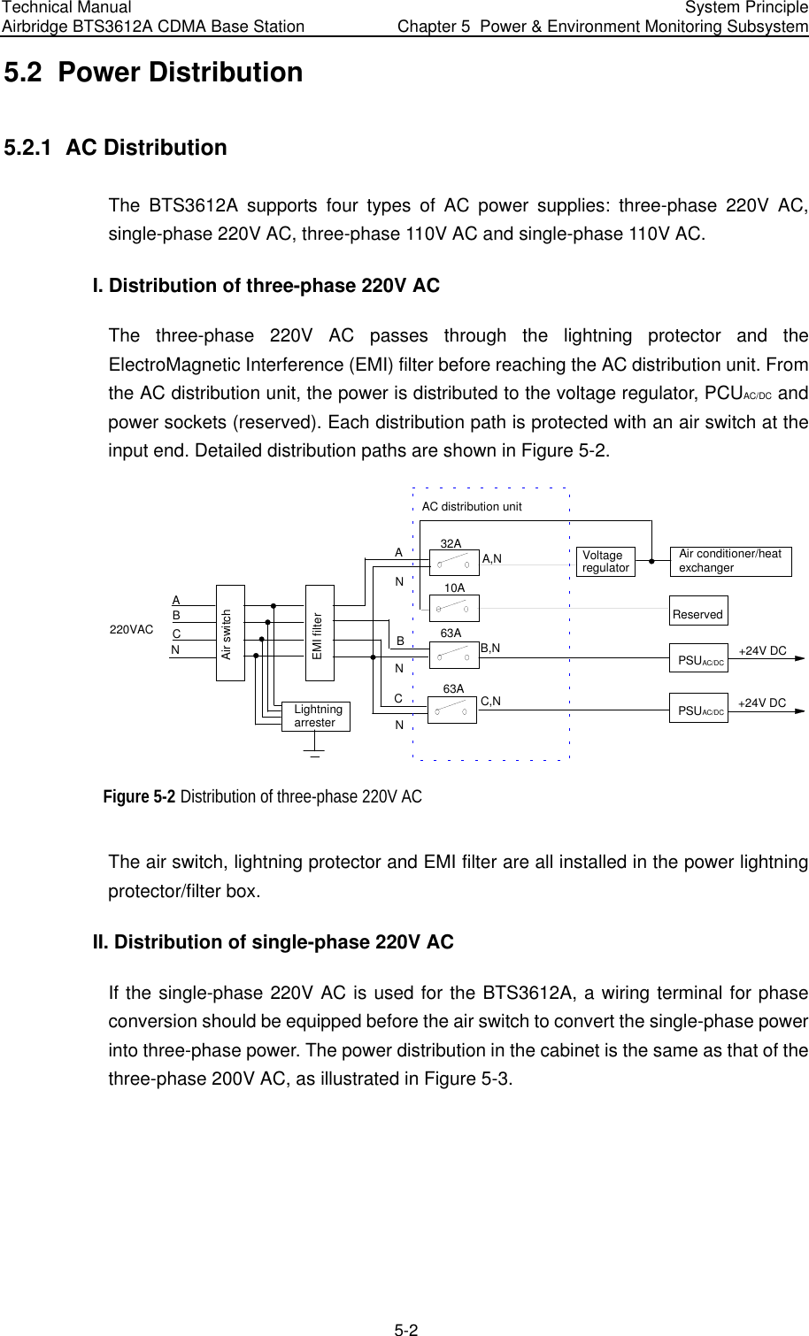
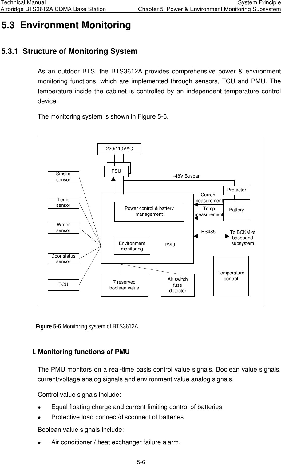
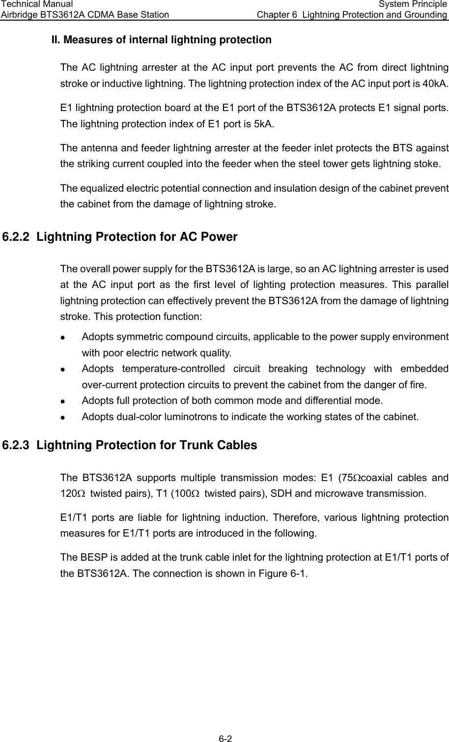
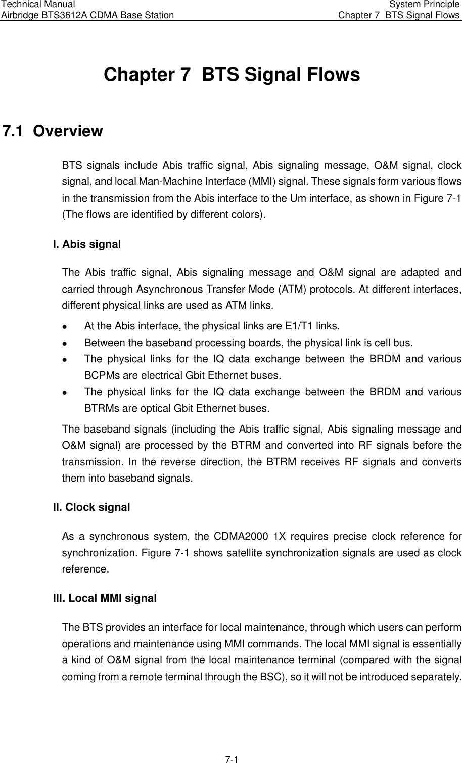
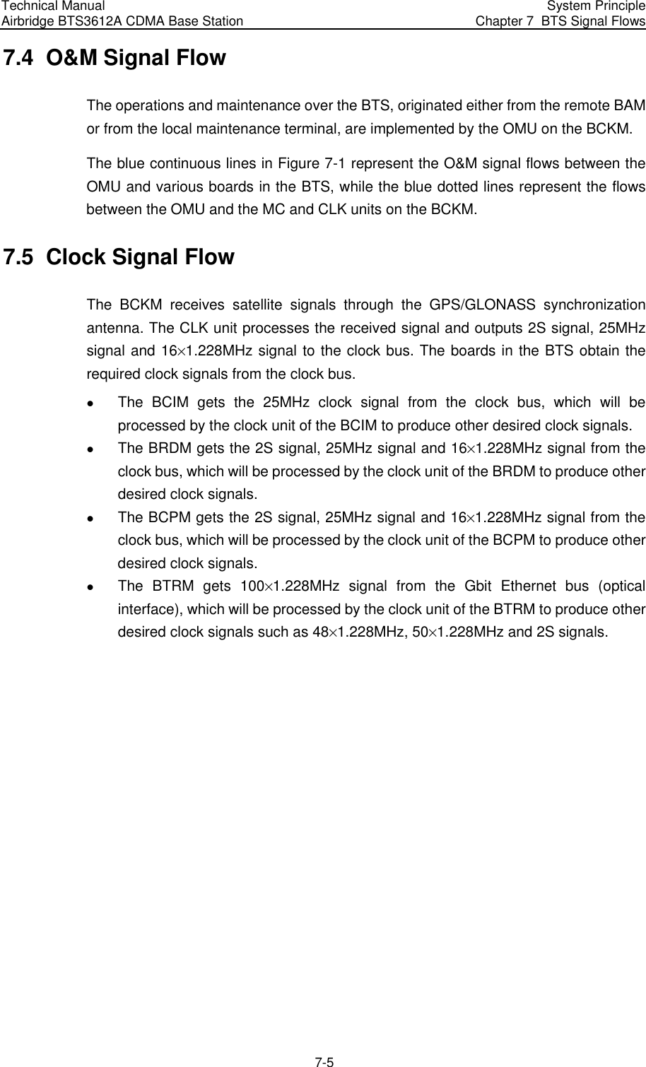
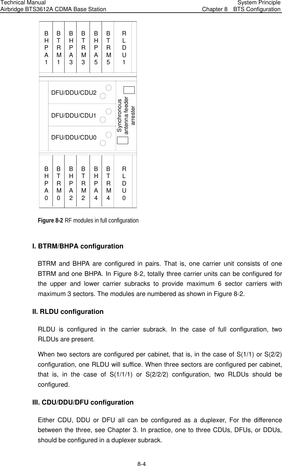
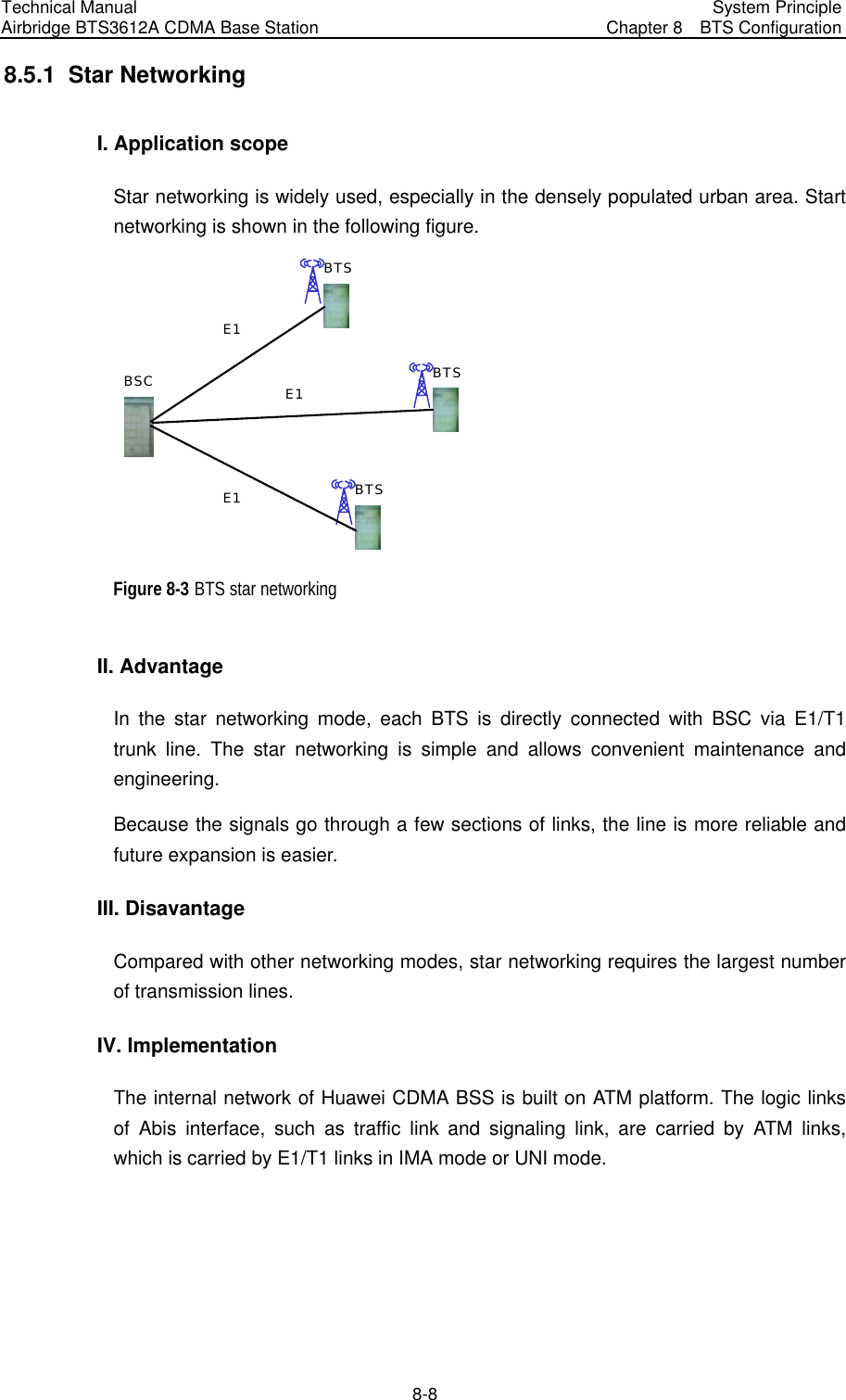
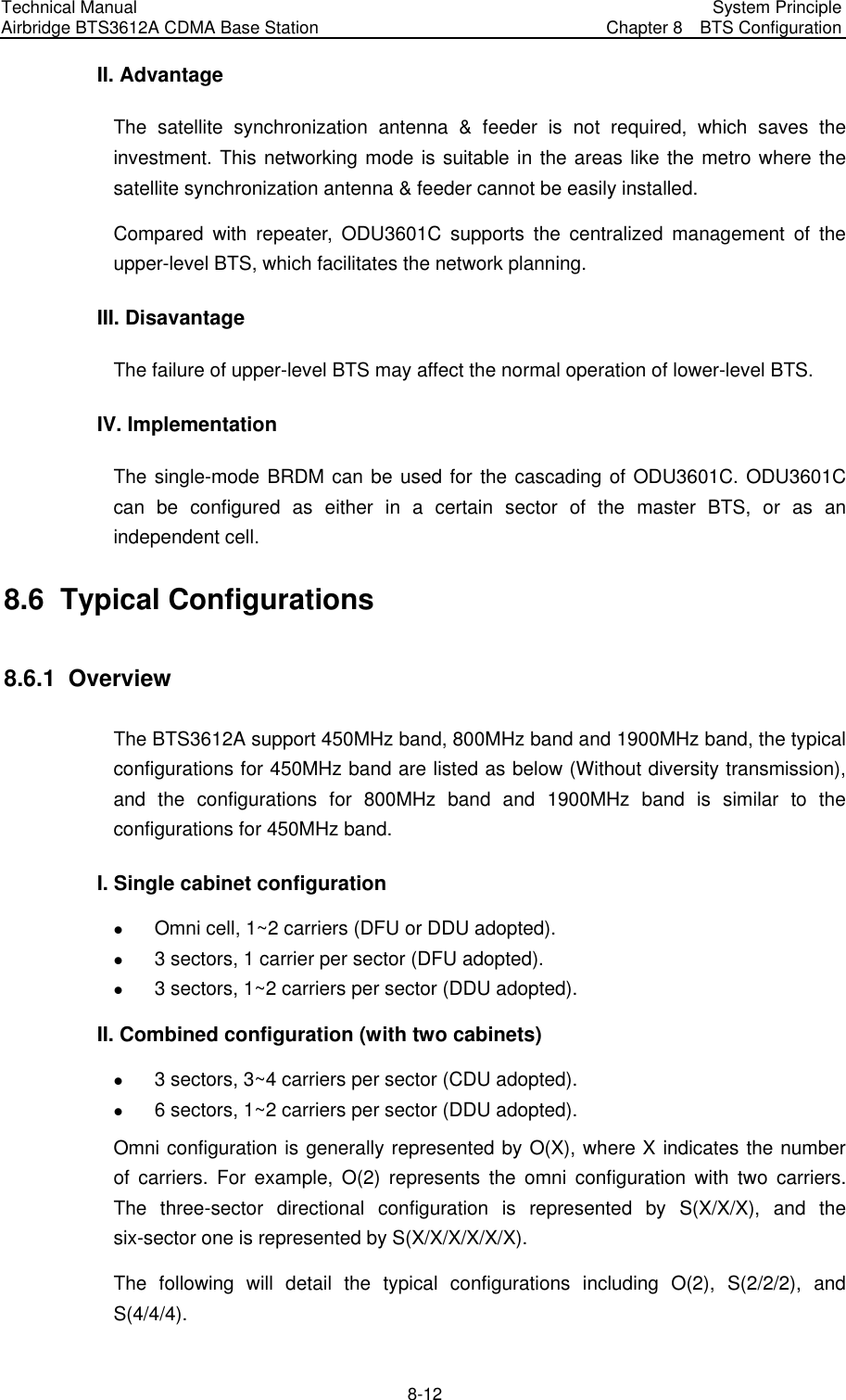
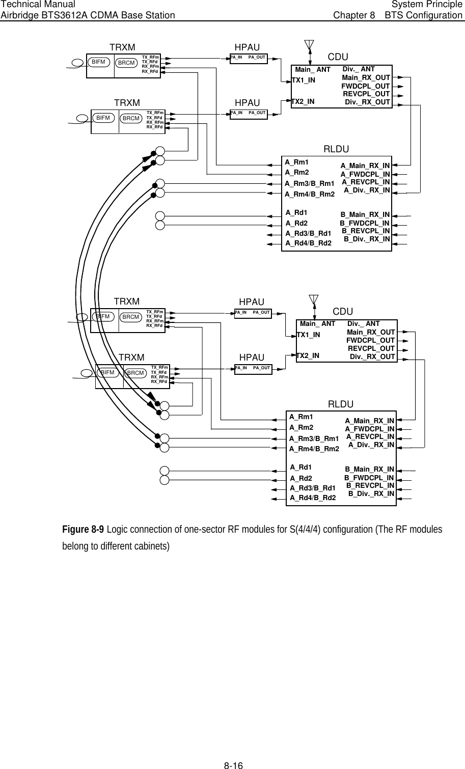
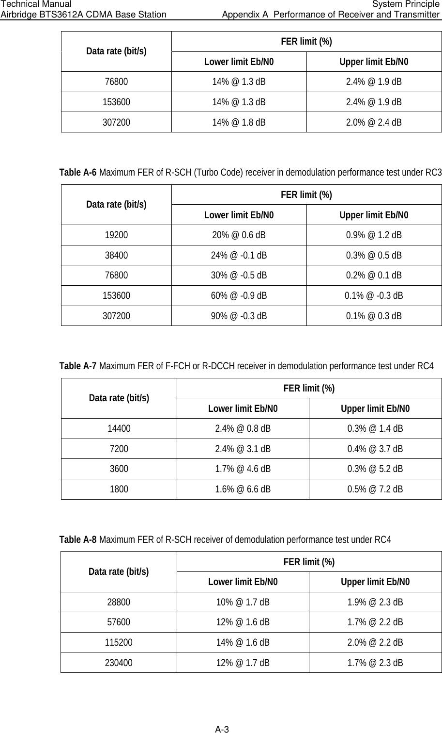
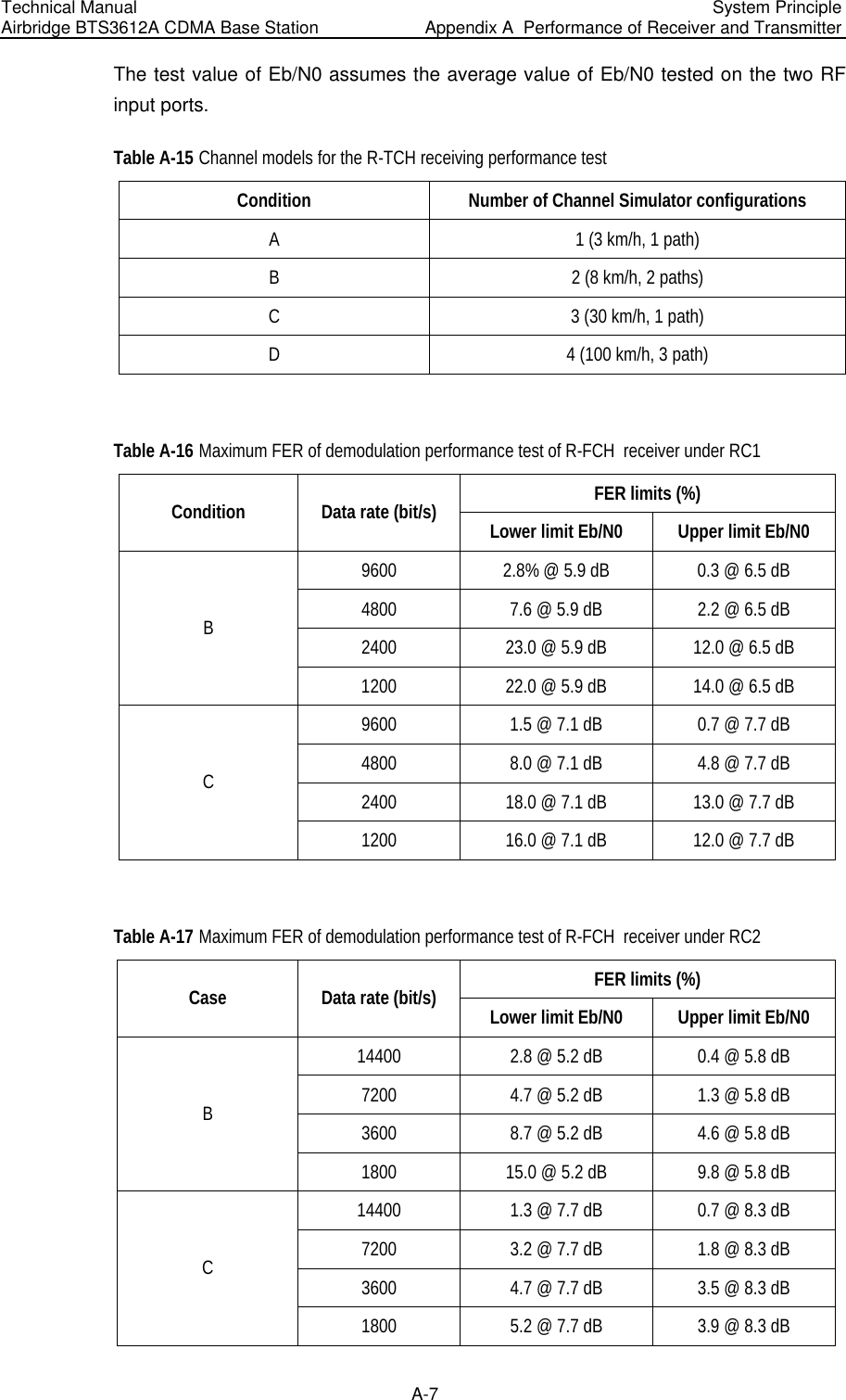
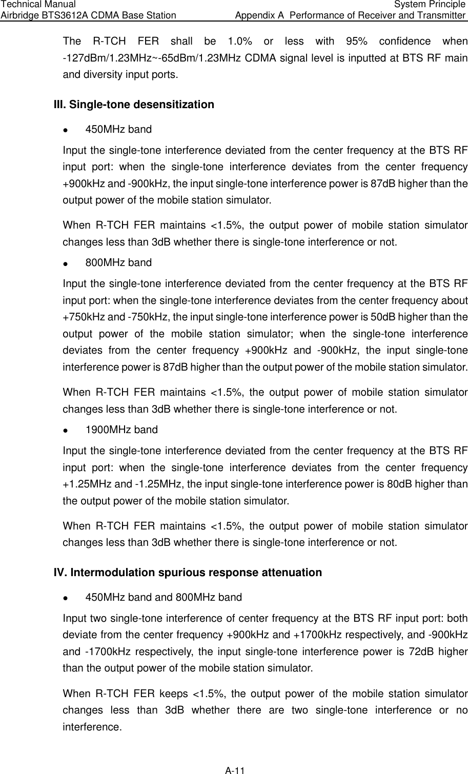
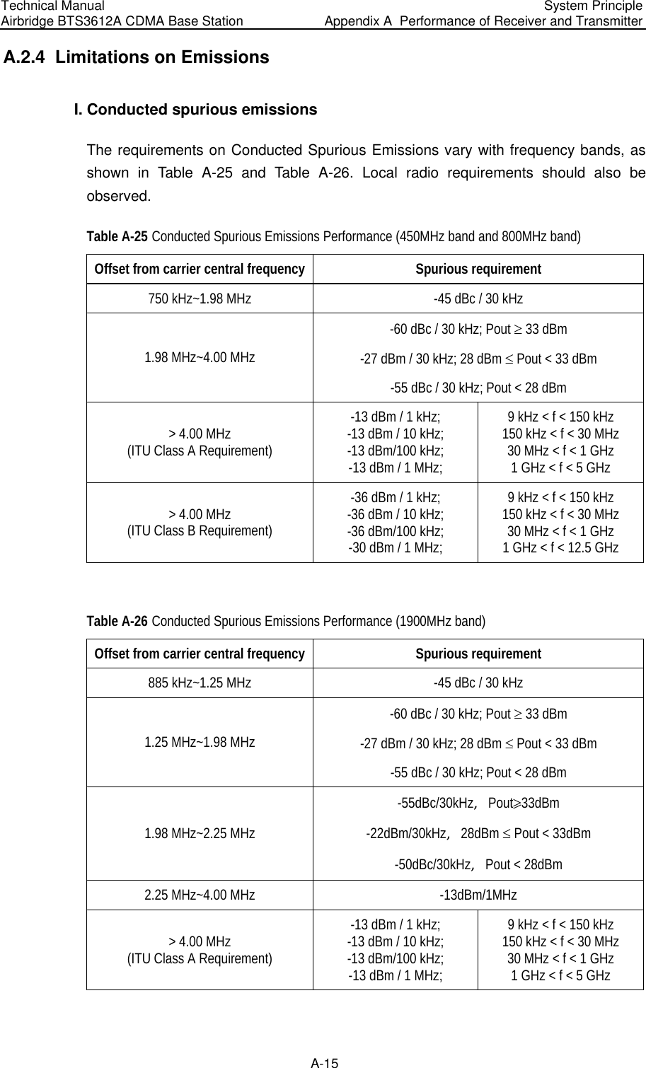
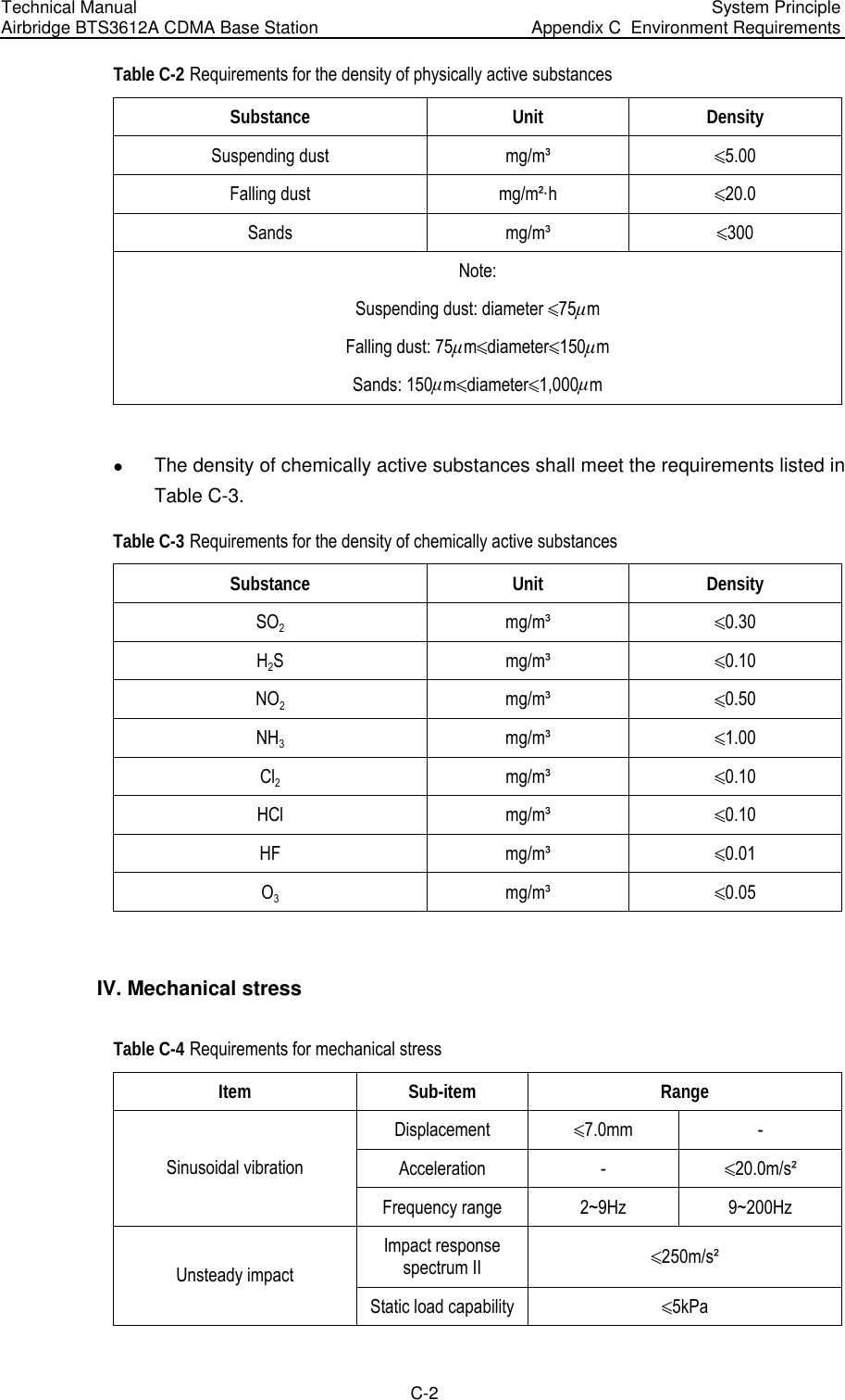
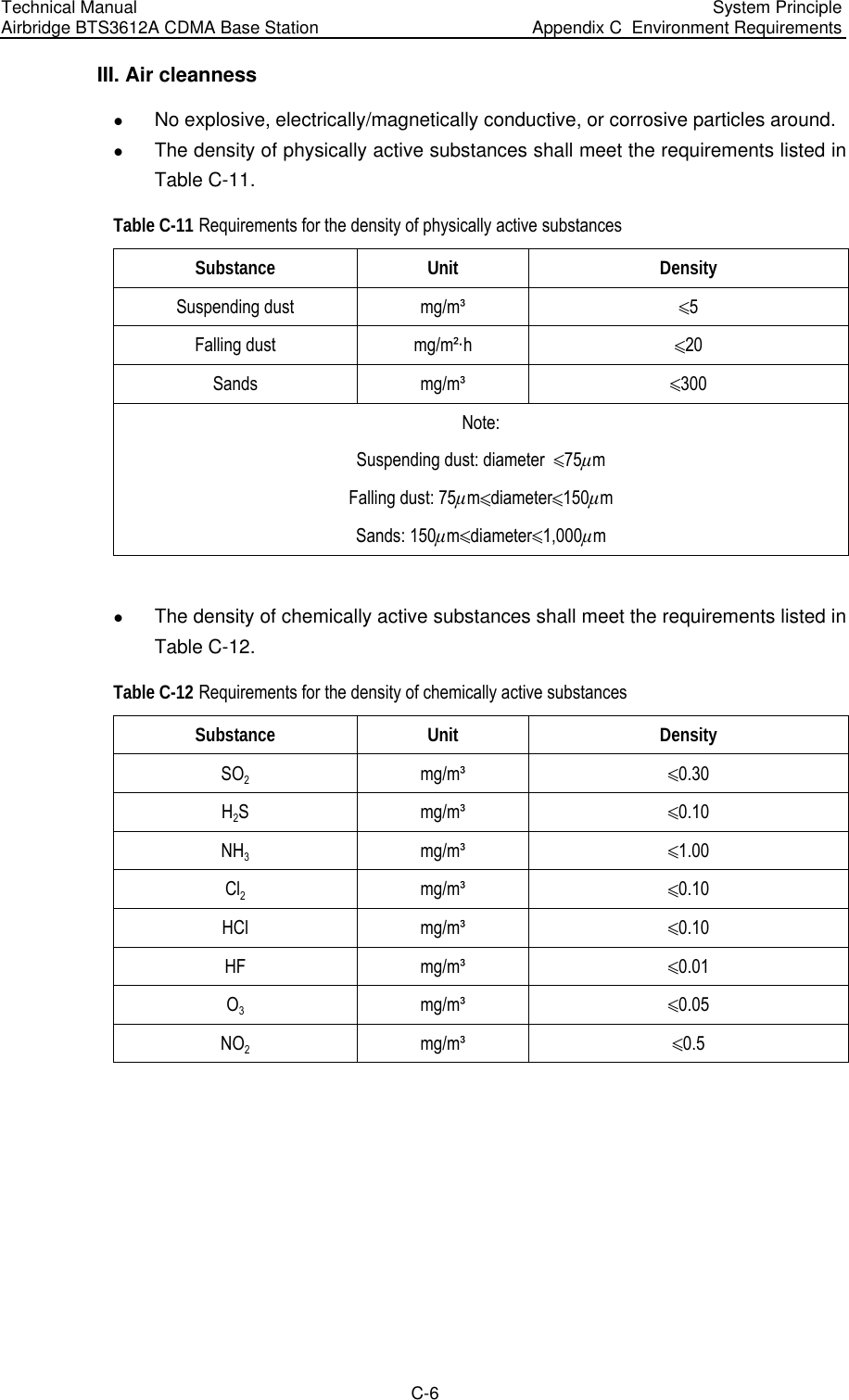
![Technical Manual Airbridge BTS3612A CDMA Base Station System Principle Appendix B EMC Performance B-4 the outdoor should all satisfy the requirements for surge immunity. The indices are shown in Table B-7. Table B-7 Surge immunity indices Port Level Performance class AC port Line~line, 2kV Line~ground, 4kV B Control line, signal line Line~line, 0.5kV Line~ground, 1kV B Control line, signal line (outdoors) Line~line, 1kV Line~ground, 2kV B Note: The test method complies with IEC61000-4-5 [11]. VI. Common-mode fast transient pulse immunity The signal & data line between CDMA cabinets and that connected with other systems (such as E1 trunk line), control line and cable connected to DC input/output port, should satisfy the requirements for fast transient pulse immunity. The indices are shown in Table B-8. Table B-8 Common-mode fast transient pulse immunity indices Port Level Performance class Signal control line port 0.5kV B DC line input/output port 1kV B AC line input port 2kV B](https://usermanual.wiki/Huawei-Technologies/BTS3612A-1900.User-Manual-Part-3/User-Guide-384040-Page-112.png)
![Technical Manual Airbridge BTS3612A CDMA Base Station System Principle Appendix D Electromagnetic Radiation D-3 Power density S [mW/cm2] for controlled area at 880 MHz 2/9.2300880300][ cmmWMHzfS=== Power density S [mW/cm2] for uncontrolled area at 880 MHz 2/58.015008801500][ cmmWMHzfS=== D.3 Estimation of Exposure to Electromagnetic Fields The following method describes a theoretical approach to calculate possible exposure to electromagnetic radiation around a BTS antenna. Precise statements are basically only possible either with measurements or complex calculations considering the complexity of the environment (e.g. soil conditions, near buildings and other obstacles) which causes reflections, scattering of electromagnetic fields. The maximum output power (given in EIRP) of a BTS is usually limited by license conditions of the network operator. A rough estimation of the expected exposure in power flux density on a given point can be made with the following equation. The calcualtions are based on FCC OET 65 Appendix B. π∗∗∗=)(4)(2mrGWPSnumeric Whereas: P = Maximum output power in W of the site G numeric = Numeric gain of the antenna relative to isotropic antenna R = distance between the antenna and the point of exposure in meters D.4 Calculation of Safe Distance Calculation of safe distane can be made on a site by site basis to ensure the power density is below the specified limitse. Or guidelines can be done beforehand to ensure the minimum distances from the antenna is maintained through the site planning.](https://usermanual.wiki/Huawei-Technologies/BTS3612A-1900.User-Manual-Part-3/User-Guide-384040-Page-123.png)
![Technical Manual Airbridge BTS3612A CDMA Base Station System Principle Appendix D Electromagnetic Radiation D-4 SPtGrdπ4**64.1= Whereas: r = distance from the antenna [m] dG= Antenna gain relative to half wave dipole Pt = Power at the antenna terminals [W] S = power density [W/m2] see also MPE Limits Note: 1mW/cm2 = 10W/m2 D.5 Location of BTS Antennae BTS antennas, the source of the radiation, are usually mounted on freestanding towers, with a height up to 30 m or on a tower on the top of buildings or, in some cases, to the side of the building. Generally the height of the antenna position does not fall below 10 m. The power usually is focused into a horizontal main beam and slightly downward tilted. The remaining power goes into the weaker beams on both side of the main beam. The main beam however does not reach ground level until the distance from the antenna position is around 50~200 m. The highest level of emission would be expected in close vicinity of the antenna and in line of sight to the antenna. D.5.1 Exclusion Zones Antenna location should be designed so that the public cannot access areas where the RF radiation exceeds the levels as described above. . If there are areas accessible to workers that exceed the RF radiation exceeds the levels as described above make sure that workers know where these areas are, and that they can (and do) power-down (or shut down) the transmitters when entering these areas. Such areas may not exist; but if they do, they will be confined to areas within 10 m of the antennas. Each exclusion zone should be defined by a physical barrier and by a easy recognizable sign warning the public or workers that inside the exclusion zone the RF radiation might exceed national limits.](https://usermanual.wiki/Huawei-Technologies/BTS3612A-1900.User-Manual-Part-3/User-Guide-384040-Page-124.png)