Huawei Technologies BTS3612A-1900 CDMA Base Station User Manual Part 3
Huawei Technologies Co.,Ltd CDMA Base Station Part 3
Contents
- 1. User Manual Part 1
- 2. User Manual Part 2
- 3. User Manual Part 3
User Manual Part 3

Technical Manual
Airbridge BTS3612A CDMA Base Station System Principle
Table of Contents
i
Table of Contents
Chapter 1 Overall Structure.......................................................................................................... 1-1
1.1 Physical Structure.............................................................................................................. 1-1
1.2 Functional Structure........................................................................................................... 1-3
Chapter 2 Baseband Subsystem ................................................................................................. 2-1
2.1 Overview............................................................................................................................ 2-1
2.1.1 Functional Structure ................................................................................................ 2-1
2.1.2 Introduction to Baseband Boards............................................................................ 2-1
2.2 BCKM................................................................................................................................. 2-2
2.2.1 Overview ................................................................................................................. 2-2
2.2.2 Structure and Principle............................................................................................ 2-2
2.2.3 External Interfaces .................................................................................................. 2-4
2.2.4 Indices..................................................................................................................... 2-5
2.3 BCIM.................................................................................................................................. 2-5
2.3.1 Overview ................................................................................................................. 2-5
2.3.2 Structure and Principle............................................................................................ 2-5
2.3.3 External Interfaces .................................................................................................. 2-7
2.3.4 Indices..................................................................................................................... 2-7
2.4 BCPM................................................................................................................................. 2-7
2.4.1 Overview ................................................................................................................. 2-7
2.4.2 Structure and principle ............................................................................................ 2-8
2.4.3 External Interfaces .................................................................................................. 2-9
2.4.4 Indices...................................................................................................................2-10
2.5 BRDM .............................................................................................................................. 2-10
2.5.1 Overview ............................................................................................................... 2-10
2.5.2 Structure and Principle.......................................................................................... 2-10
2.5.3 External Interfaces ................................................................................................ 2-12
2.5.4 Indices...................................................................................................................2-13
2.6 BASB ............................................................................................................................... 2-13
2.6.1 Overview ............................................................................................................... 2-13
2.6.2 Structure and Principle.......................................................................................... 2-13
2.6.3 External Interfaces ................................................................................................ 2-14
2.6.4 Indices...................................................................................................................2-14
2.7 BESP ............................................................................................................................... 2-14
2.7.1 Overview ............................................................................................................... 2-14
2.7.2 Structure and Principle.......................................................................................... 2-15
2.7.3 External Interfaces ................................................................................................ 2-16
2.7.4 Indices...................................................................................................................2-16

Technical Manual
Airbridge BTS3612A CDMA Base Station System Principle
Table of Contents
ii
2.8 BFAN ............................................................................................................................... 2-17
2.8.1 BFMM.................................................................................................................... 2-17
2.8.2 BFIB ......................................................................................................................2-19
Chapter 3 Radio Frequency Subsystem ..................................................................................... 3-1
3.1 Overview............................................................................................................................ 3-1
3.1.1 Radio Frequency Subsystem Functional Structure................................................. 3-1
3.1.2 Introduction to RF Modules..................................................................................... 3-2
3.2 BTRM................................................................................................................................. 3-2
3.2.1 Overview ................................................................................................................. 3-2
3.2.2 Structure and Principle............................................................................................ 3-3
3.2.3 External Interfaces .................................................................................................. 3-5
3.2.4 Indices..................................................................................................................... 3-6
3.3 BHPA ................................................................................................................................. 3-6
3.3.1 Overview ................................................................................................................. 3-6
3.3.2 Structure and Principle............................................................................................ 3-6
3.3.3 External Interfaces .................................................................................................. 3-8
3.3.4 Indices..................................................................................................................... 3-8
3.4 BTRB ................................................................................................................................. 3-8
3.4.1 Overview ................................................................................................................. 3-8
3.4.2 Structure and Principle............................................................................................ 3-8
3.4.3 External Interfaces .................................................................................................. 3-9
3.4.4 Indices...................................................................................................................3-10
3.5 CDU ................................................................................................................................. 3-10
3.5.1 Overview ............................................................................................................... 3-10
3.5.2 Structure and Principle.......................................................................................... 3-10
3.5.3 External Interfaces ................................................................................................ 3-11
3.5.4 Indices...................................................................................................................3-12
3.6 DFU.................................................................................................................................. 3-12
3.6.1 Overview ............................................................................................................... 3-12
3.6.2 Structure and Principle.......................................................................................... 3-12
3.6.3 External Interfaces ................................................................................................ 3-13
3.6.4 Indices...................................................................................................................3-13
3.7 DDU ................................................................................................................................. 3-14
3.7.1 Overview ............................................................................................................... 3-14
3.7.2 Structure and Principle.......................................................................................... 3-14
3.7.3 External Interfaces ................................................................................................ 3-15
3.7.4 Indices...................................................................................................................3-15
3.8 RLDU ............................................................................................................................... 3-16
3.8.1 Overview ............................................................................................................... 3-16
3.8.2 Structure and Principle.......................................................................................... 3-16
3.8.3 External Interfaces ................................................................................................ 3-17
3.8.4 Indices...................................................................................................................3-18

Technical Manual
Airbridge BTS3612A CDMA Base Station System Principle
Table of Contents
iii
3.9 BRFM............................................................................................................................... 3-18
3.9.1 BBFM .................................................................................................................... 3-18
3.9.2 BBFL ..................................................................................................................... 3-20
Chapter 4 Antenna & Feeder Subsystem.................................................................................... 4-1
4.1 Overview............................................................................................................................ 4-1
4.2 RF Antenna & Feeder........................................................................................................ 4-1
4.2.1 Antenna...................................................................................................................4-1
4.2.2 Feeder..................................................................................................................... 4-3
4.2.3 Lightning Arrester (Optional)................................................................................... 4-3
4.2.4 Tower-top Amplifier (Optional) ................................................................................ 4-4
4.3 Satellite Synchronization Antenna & Feeder..................................................................... 4-4
4.3.1 Overview ................................................................................................................. 4-4
4.3.2 Antenna...................................................................................................................4-7
4.3.3 Feeder..................................................................................................................... 4-7
4.3.4 Lightning Arrester.................................................................................................... 4-7
4.3.5 Receiver ..................................................................................................................4-7
Chapter 5 Power & Environment Monitoring Subsystem ......................................................... 5-1
5.1 Overview............................................................................................................................ 5-1
5.2 Power Distribution.............................................................................................................. 5-2
5.2.1 AC Distribution ........................................................................................................ 5-2
5.2.2 DC Distribution ........................................................................................................ 5-3
5.2.3 Power Distribution Devices ..................................................................................... 5-5
5.3 Environment Monitoring..................................................................................................... 5-6
5.3.1 Structure of Monitoring System............................................................................... 5-6
5.3.2 Monitoring Devices.................................................................................................. 5-7
Chapter 6 Lightning Protection and Grounding......................................................................... 6-1
6.1 Overview............................................................................................................................ 6-1
6.2 BTS Lightning Protection Principle .................................................................................... 6-1
6.2.1 Principle and Characteristics................................................................................... 6-1
6.2.2 Lightning Protection for AC Power.......................................................................... 6-2
6.2.3 Lightning Protection for Trunk Cables..................................................................... 6-2
6.2.4 Lighting Protection for Antenna & Feeder Subsystem............................................ 6-3
6.3 Grounding of BTS Equipment............................................................................................ 6-4
6.3.1 Internal Grounding of Cabinet................................................................................. 6-4
6.3.2 External Grounding of Cabinet................................................................................ 6-4
6.3.3 Grounding of AC Lightning Arrester........................................................................ 6-4
6.3.4 Grounding of Transmission Equipment................................................................... 6-5
6.3.5 Grounding of Overhead E1/T1 and HDSL Cables.................................................. 6-5
6.3.6 Grounding of BTS Surge Protector ......................................................................... 6-5
Chapter 7 BTS Signal Flows......................................................................................................... 7-1
7.1 Overview............................................................................................................................ 7-1

Technical Manual
Airbridge BTS3612A CDMA Base Station System Principle
Table of Contents
iv
7.2 Abis Traffic Signal Flow ..................................................................................................... 7-3
7.3 Abis Signaling Message Flow............................................................................................ 7-4
7.4 O&M Signal Flow ............................................................................................................... 7-5
7.5 Clock Signal Flow .............................................................................................................. 7-5
Chapter 8 BTS Configuration....................................................................................................... 8-1
8.1 Configuration Principle....................................................................................................... 8-1
8.2 Configuration of Main Equipment ...................................................................................... 8-1
8.2.1 Configuration of Baseband Boards ......................................................................... 8-1
8.2.2 Configuration of RF Modules .................................................................................. 8-3
8.2.3 Configuration of Power Modules............................................................................. 8-5
8.3 Configuration of Auxiliary Equipment................................................................................. 8-5
8.3.1 Batteries .................................................................................................................. 8-5
8.3.2 Temperature Control Device................................................................................... 8-6
8.3.3 Monitoring Devices.................................................................................................. 8-6
8.3.4 Transmission Equipment......................................................................................... 8-7
8.4 Configuration of Antenna and Feeder ............................................................................... 8-7
8.5 Networking Configuration .................................................................................................. 8-7
8.5.1 Star Networking....................................................................................................... 8-8
8.5.2 Chain Networking.................................................................................................... 8-9
8.5.3 Tree Networking.................................................................................................... 8-10
8.5.4 Fractional ATM Networking................................................................................... 8-11
8.5.5 Cascading with ODU3601Cs ................................................................................ 8-11
8.6 Typical Configurations ..................................................................................................... 8-12
8.6.1 Overview ............................................................................................................... 8-12
8.6.2 S(2/2/2) Configuration........................................................................................... 8-13
8.6.3 S(4/4/4) Configuration........................................................................................... 8-14
Appendix A Performance of Receiver and Transmitter.............................................................A-1
A.1 Performance of Receiver...................................................................................................A-1
A.1.1 Frequency Coverage ..............................................................................................A-1
A.1.2 Access Probe Acquisition .......................................................................................A-1
A.1.3 R-TCH Demodulation Performance........................................................................A-1
A.1.4 Receiving Performance ........................................................................................A-10
A.1.5 Limitations on Emissions ......................................................................................A-12
A.1.6 Received Signal Quality Indicator (RSQI) ............................................................A-12
A.2 Performance of Transmitter.............................................................................................A-13
A.2.1 Frequency Requirements .....................................................................................A-13
A.2.2 Modulation Requirements.....................................................................................A-13
A.2.3 RF Output Power ..................................................................................................A-14
A.2.4 Limitations on Emissions ......................................................................................A-15
Appendix B EMC Performance ....................................................................................................B-1
B.1 EMI Performance...............................................................................................................B-1

Technical Manual
Airbridge BTS3612A CDMA Base Station System Principle
Table of Contents
v
B.2 EMS Performance .............................................................................................................B-2
Appendix C Environment Requirements ....................................................................................C-1
C.1 Storage Environment ........................................................................................................C-1
C.2 Transportation Environment..............................................................................................C-3
C.3 Operation Environment .....................................................................................................C-5
Appendix D Electromagnetic Radiation......................................................................................D-1
D.1 Introduction........................................................................................................................D-1
D.2 Maximum Permissible Exposure.......................................................................................D-1
D.3 Estimation of Exposure to Electromagnetic Fields............................................................D-3
D.4 Calculation of Safe Distance.............................................................................................D-3
D.5 Location of BTS Antennae ................................................................................................D-4
D.5.1 Exclusion Zones .....................................................................................................D-4
D.5.2 Guidelines on Arranging Antenna Locations..........................................................D-5
Appendix E Abbreviations and Acronyms .................................................................................E-1
Technical Manual
Airbridge BTS3612A CDMA Base Station System Principle
Chapter 1 Overall Structure
1-1
Chapter 1 Overall Structure
1.1 Physical Structure
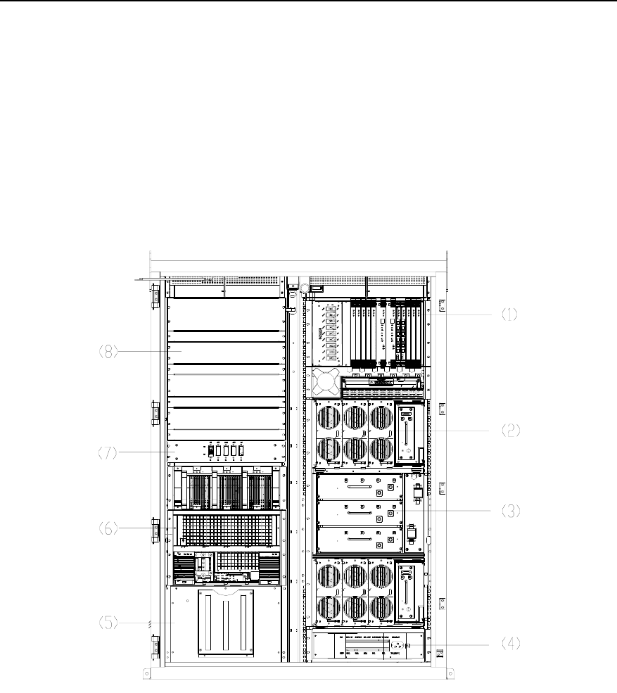
A BTS3612A cabinet in full configuration is composed of two parts, as shown in Figure
1-1. The right half is the main cabinet, while the left half is for the auxiliary devices.
(1) Baseband subrack (2) Carrier subrack
(3) Duplexer subrack (4) AC distribution/lightning protector/wave filter unit
(5) Battery subrack (6)Power supply subrack
(7) Auxiliary cabinet secondary power switch box (8) Transmission equipment subrack
Figure 1-1 BTS3612A cabinet in full configuration
I. Main cabinet
The main cabinet is used to hold the baseband processing boards, Radio Frequency
(RF) modules, etc.
z Baseband subrack

Technical Manual
Airbridge BTS3612A CDMA Base Station System Principle
Chapter 1 Overall Structure
1-2
The baseband subrack is configured with various baseband processing boards, such
as BCIM, BCPM, BCKM and BRDM.
A main cabinet secondary power switch box is configured to the left of the subrack.
With the secondary power switch box, each board and module can be separately
powered by the PSUDC/DC. All the baseband processing boards share one power switch.
Each pair of BTRM and BHPA boards share one power switch. The RLDU has its own
power switch.
z Carrier subrack
There are two carrier subracks used to configure the carrier units, each of which is
composed of one BTRM and one BHPA. Each subrack can be configured with one
RLDU.
z Duplexer subrack
The duplexer subrack is located between the upper and lower carrier subracks. It is
configured with duplexer units DFU or DDU as needed.
To the right of the subrack is a lightning protector connecting to the GPS/GLONASS
synchronization antenna.
z Other devices
Between the baseband subrack and the upper carrier subrack are the fiber flange,
cabling trough, fan box and air inlet.
The cabling trough is used to route the satellite signal receiving cable and fibers
(connecting the BRDM and carrier modules). The extra fibers can be coiled on the fiber
flange.
The fan box, the air inlet and air outlet (on the top of the cabinet) form a ventilation path
to discharge the heat in the baseband subrack.
II. Auxiliary cabinet
The auxiliary cabinet is configured with the PSUAC/DC, PSUDC/DC, storage batteries, and
built-in transmission equipment.
z Transmission equipment subrack
Standard space is reserved in this subrack to accommodate microwave, High-speed
Digital Subscriber Line (HDSL), or SDH transmission equipment so as to support
various networking modes.
z Power supply subrack
The power supply subrack is configured with PSUDC/DC and PSUAC/DC. A Power
Monitoring Unit (PMU) can also be installed.
z Battery subrack
Technical Manual
Airbridge BTS3612A CDMA Base Station System Principle
Chapter 1 Overall Structure
1-3
The battery subrack can be configured with storage batteries or DC lightning
protector/wave filter, based on actual configuration requirements.
z Other devices
A lightning protection board and an auxiliary cabinet secondary power switch box are
configured between the transmission equipment subrack and the power supply
subrack.
E1 Surge Protector (BESP) or SDH surge protector can be used, according to the
transmission equipment configured.
The secondary power switch box is used to control the power supply to the PSUAC/DC.
III. Cabinet door
Temperature-control device, such as air conditioner or heat exchanger, are equipped
on the cabinet door.
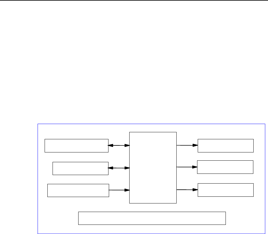
1.2 Functional Structure
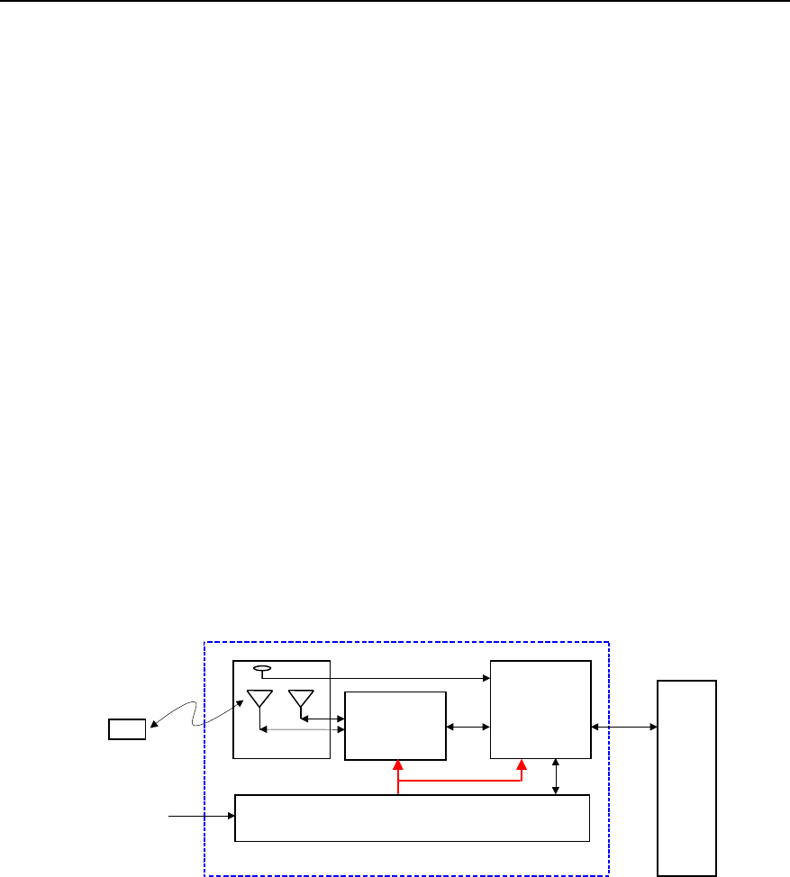
Functionally, the BTS3612A system is composed of the baseband subsystem, Radio
Frequency (RF) subsystem, antenna & feeder subsystem, and power & environment
monitor subsystem, as shown in Figure 1-2.
BSC
Baseband
subsystem
Power & environment monitor subsystem
Radio Frequency
subsystem
Abis
interface
Um
interface
MS Antenna & feeder
subsystem
220V AC
or
110V AC
BTS3612A
Figure 1-2 BTS3612A system structure
Standard space is reserved in the cabinet to accommodate transmission equipment
such as microwave and SDH so as to support different networking modes.
The following chapters will detail each subsystem of BTS3612A.
Technical Manual
Airbridge BTS3612A CDMA Base Station System Principle
Chapter 2 Baseband Subsystem
2-1
Chapter 2 Baseband Subsystem
2.1 Overview
Baseband subsystem consists of BTS Control & Clock Module (BCKM), BTS Resource
Distribution Module (BRDM), BTS Channel Processing Module (BCPM), BTS Control
Interface Module (BCIM) and Baseband Backplane (BASB).
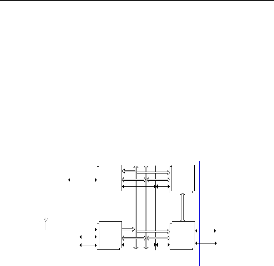
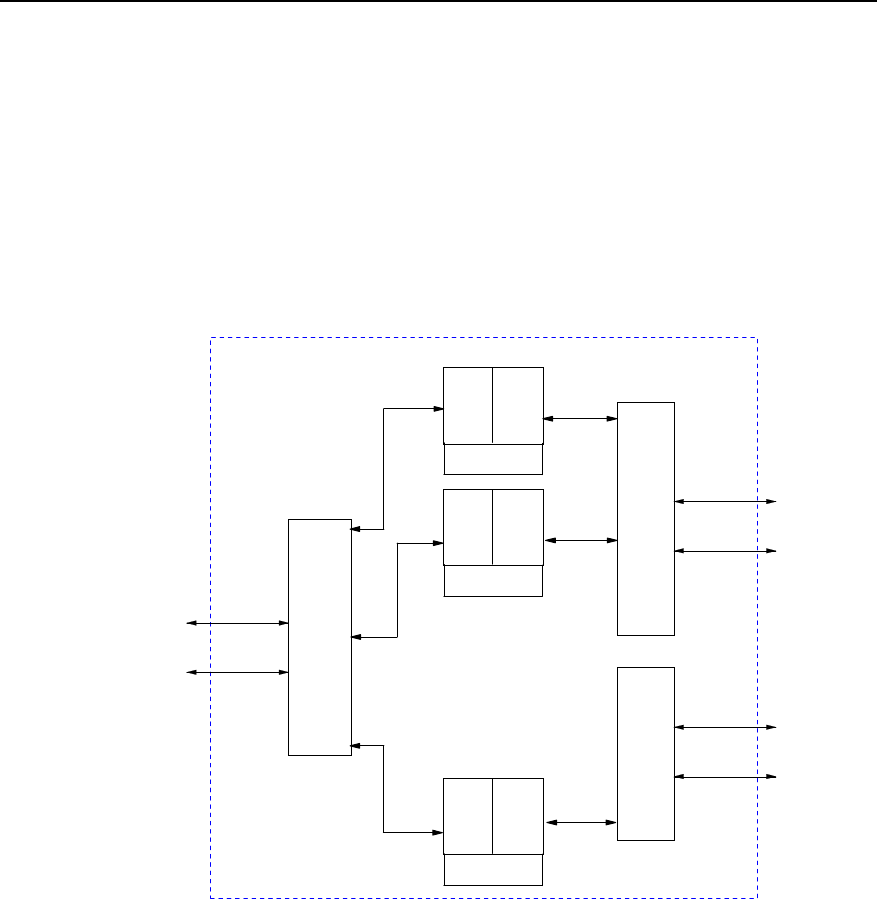
2.1.1 Functional Structure
The functional structure of baseband subsystem is shown in Figure 2-1.
BCIM
BCK
M
E1/T1
BSC BCPM
BRD
M
...
...
Other functional units
BTRM/ODU3601C
BTRM/ODU3601C
BRDM
BCPM
BCKM
BCIM
Satellite signal receiving
antenna
Clock bus
Backplane bus
Emergency serial port
High-speed data
bus
Optical fiber
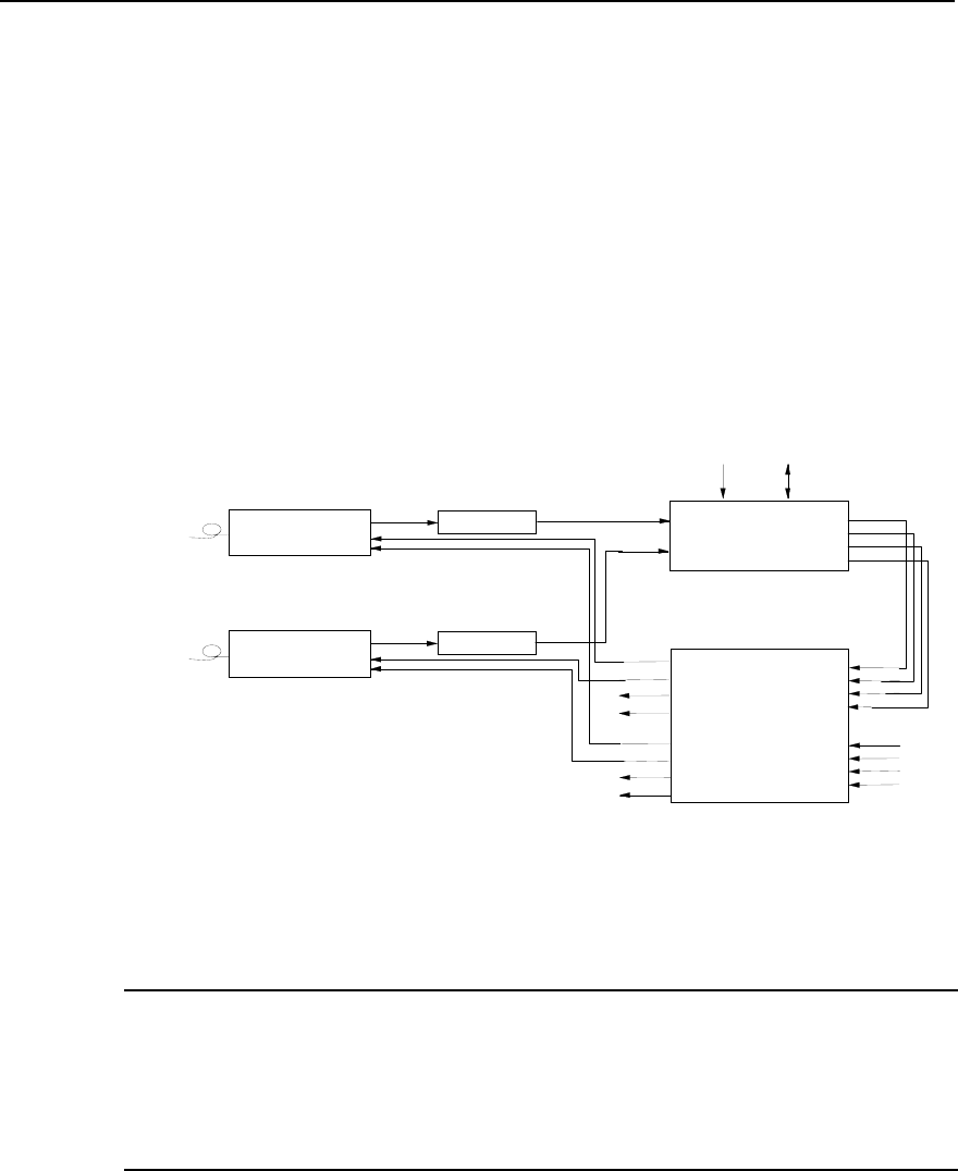
BCIM: BTS Control Interface Module BCPM: BTS Channel Process Module
BCKM: BTS Control & Clock Module BRDM: BTS Resource Distribution Module
BTRM: BTS Transceiver Module BSC: Base Station Controller
Figure 2-1 functional structure of baseband subsystem
Baseband subsystem accesses transmission system through E1/T1 interface provided
by the BCIM so as to connect to BSC equipment. It connects to carrier units through
optical interface provided by the BRDM. Carrier units can be BTRM modules of the
same BTS, or MTRM module of the ODU3601C extended afar.
2.1.2 Introduction to Baseband Boards
Baseband subsystem is held in the baseband subrack. The full configuration of
baseband subrack is as shown in Figure 2-1
Baseband subrack supports the following boards:

Technical Manual
Airbridge BTS3612A CDMA Base Station System Principle
Chapter 2 Baseband Subsystem
2-2
z BCKM: BTS control & clock module, providing clock for BTS system and realizing
the control of BTS system resource.
z BCIM: BTS control interface module, used for accessing transmission system to
connect to the BSC. It supports E1/T1 transmission.
z BCPM: BTS channel process module, processing the data of CDMA forward
channel and reverse channel.
z BRDM: BTS resource distribution module, connecting BCPM to BTRM to realize
the work mode of BCPM resource pool.
In addition to the boards introduced, this section also covers the backplane of
baseband subrack, E1 lightning-protection board and fan module.
2.2 BCKM
2.2.1 Overview
BCKM controls and manages the entire BTS system. Its functions are listed as follows:
Main control functions: Call procedure control, signaling processing, resource
management, channel management, cell configuration, etc.
Operation & maintenance functions (O&M): BTS operation and maintenance, such as
software download, status management, data configuration, test management,
interface tracing, fault management, log management, maintenance console interface,
active/standby BCKM switchover, etc.
Clock function: It provides high-precision oscillation clock and can be synchronized
with an external clock (such as GPS/GLONASS clock). Thus it provides the entire BTS
system with reference clock signal.
In addition, BCKM also provides external interfaces. See the following sections for
detail.
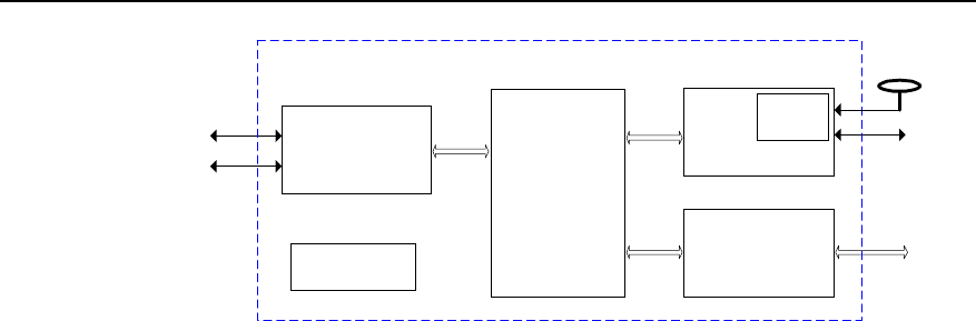
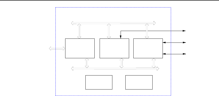
2.2.2 Structure and Principle
The structure of BCKM module is as shown in Figure 2-2.
Technical Manual
Airbridge BTS3612A CDMA Base Station System Principle
Chapter 2 Baseband Subsystem
2-3
Power supply
module
External
communication
module
Clock
module
Backplane
bus module
Other
functional
units CPU
module
BCKM
...
Satellite
signal
receiver
BASB
BASB
Figure 2-2 Structure of BCKM module
The BCKM comprises the following parts:
I. Clock module
Clock module is the clock source of BTS, which provides working clock for various
boards.
Clock module supports two work modes: External synchronization mode (locked mode)
and free oscillation mode (holdover mode). In the former mode, it receives
GPS/GLONASS clock signals through its satellite signal receiver. In the latter mode, it
provides clock reference through high precision oscillator (oven control & voltage
control oscillator).
For the introduction to satellite signal receiver, see “4.3.5 Receiver”.
II. CPU module
CPU module controls logical circuits to initialize relevant components. The
management and control of BTS system is implemented through its system software,
which includes main control software and operation & maintenance software. For
specific function, see ”2.1 Overview”.
III. Backplane bus module
The communication port of the Central Processing Unit (CPU) is connected with other
boards of BTS through the backplane bus module, and processes or transmits O&M
signaling from other boards of BTS (BRDM, BCPM and BCIM).
IV. External communication module
External communication module utilizes the multiple communication control ports
provided by the main control CPU to implement functions such as maintenance

Technical Manual
Airbridge BTS3612A CDMA Base Station System Principle
Chapter 2 Baseband Subsystem
2-4
console interface, environment monitoring interface, test interface and external
synchronization interface.
V. Power supply module
The power supply module converts +24V input power into +5V, +3.3V and +2.5V for
various modules of local board.
2.2.3 External Interfaces
z Local maintenance console interface
This interface is a 10/100M compatible Ethernet interface to connect with local
maintenance console.
z Remote maintenance serial port
This port is a RS232 serial port to connect with the Modem so as to provide remote
monitoring and maintenance in case of interruption of OML link.
z Environment alarm interface
This port is a RS485 serial port to connect with an external monitoring device so as to
collect and process the equipment room environment information (such as fire, water,
temperature and humidity alarms).
z GPS/GLONASS antenna interface
It is used to receive satellite signal from the GPS/GLONASS so as to provide
GPS/GLONASS antenna with +5V feed.
z External synchronization interface
If the GPS/GLONASS is not available, the system clock can keep synchronization with
external clock system.
z Test interface
It is an interface for BTS test, providing 10MHz and 2s signals
z Backplane interface
It includes backplane bus interface, clock bus interface, and emergency serial port. The
board management is accomplished through backplane bus. Other boards are
provided with clock signal through clock bus. Boards can still keep communication
through emergency serial port in case of board fault.
z Fan module interface
Fan module interface is a RS485 serial port, used to monitor the fan module and power
supply module of baseband subrack.
z Power supply interface
Led out from the power connector on the backplane, the interface is connected with
+24V power, +24V power ground and PGND.

Technical Manual
Airbridge BTS3612A CDMA Base Station System Principle
Chapter 2 Baseband Subsystem
2-5
2.2.4 Indices
z Power voltage: +24V.
z Power consumption: <20W.
z Dimensions: 460mm%233.35mm (Length%Width).
2.3 BCIM
2.3.1 Overview
The BCIM is located in BTS baseband subrack. It is a functional entity for the
connection of BTS and BSC. Its major functions are as follows:
z In uplink direction, backplane bus receives O&M command from BCKM and traffic
data from BCPM, and transmit ATM cells on the multiple E1 links to BSC with IMA
technology in compliance with G.804 standards.
z In downlink direction, it receives ATM cells distributed on the multiple E1/T1 links
from BSC, multiplexes them into a single ATM cell flow with IMA technology and
finally sends them to corresponding processing boards through the backplane
bus.
z Each BCIM provides 8 E1/T1 links, which can support at the most 4 IMA link sets.
In BTS, there are two BCIMs, working in load sharing mode and providing physical
interfaces to BSC. At the most 16 E1/T1 links can be provided.
z It communicates with BSC through IMA state machine program on the local board
and monitors the working status of E1/T1 link to ensure the implementation of IMA
protocol.
z It transmits O&M command through backplane bus or emergency serial port,
reports the status information of the local board to BCKM and provides interface
for board maintenance and network management.
2.3.2 Structure and Principle
BCIM is available in two specifications:
z BCIM with E1 interface.
z BCIM with E1/T1 interface. This type of BCIM works either in E1 mode or T1 mode
according to the setting of the DIP switches.
Figure 2-3 illustrates the structure of BCIM with E1/T1 interface.
Technical Manual
Airbridge BTS3612A CDMA Base Station System Principle
Chapter 2 Baseband Subsystem
2-6
Backplane bus
module CPU
module
Control bus
Data bus
E1/T1
RS232
BASB
BCKM
BESP
IMA
module
...
Power supply
module
Clock
module
Figure 2-3 Structure of BCIM
BCIM comprises the following parts:
I. IMA module
IMA module inversely multiplex an ATM cell flow based on cells into multiple physical
links for transmission, and remotely multiplex the cell flows transmitted on different
physical connections into a single ATM cell flow.
In uplink direction, IMA module receives AAL2 traffic cells from BCPM and AAL5
signaling cells from BCKM through the backplane bus. It splits the ATM cell flow into
cells, transmits them on multiple E1/T1 link according to G.804 standard before
sending them to BSC.
In downlink direction, it receives ATM cells from BSC that are distributed on multiple
E1/T1 trunk lines, inversely multiplexes them into a single ATM cell flow. Then it sends
AAL2 traffic cells to BCPM and AAL5 signaling cells to BCKM through the backplane
bus.
II. CPU module
The CPU module implements such functions as IMA protocol processing, executing
OAM function of IMA, as well as E1/T1 link management and communication with
BCKM.
III. Backplane bus module
BCIM communicates with other boards in the baseband part through the backplane bus
module, including control information communication with BCKM and traffic data
communication with BCPM.

Technical Manual
Airbridge BTS3612A CDMA Base Station System Principle
Chapter 2 Baseband Subsystem
2-7
IV. Clock module
It provides working clock for the local board.
V. Power supply module
The power supply module converts +24V input power into +3.3V for various modules of
local board.
2.3.3 External Interfaces
z E1/T1 interface
Interface with BSC. BTS can be connected to the transmission system to connect to the
BSC.
z Backplane bus interface
Interface with the other boards in the baseband part.
z Emergency serial port
Emergency serial port is an RS-232 serial port, works as a slave node and is used for
communication with BCKM when other part of the board is faulty.
z Power supply interface
Led out from the power connector on the backplane, the interface is connected with
+24V power, +24V power ground and PGND.
2.3.4 Indices
z Power voltage: +24V.
z Power consumption <15W.
z Dimensions: 460mm%233.35mm (Length%Width).
2.4 BCPM
2.4.1 Overview
The BCPM is logically located between the BRDM and the BCIM. The BCPM is the
traffic processing board of the system. In full configuration, six BCPMs are needed.
Data from various forward and reverse channels are processed by this board.
The BCPM also processes digital signals, including encoding/decoding baseband
signals and one-time modulation and demodulation of baseband signals. In addition, it
processes high layer control signals. The main functions are as follows:
z In forward direction, after ATM cell data from the network side are processed by
the high performance processor, BCPM performs functions such as encoding
Technical Manual
Airbridge BTS3612A CDMA Base Station System Principle
Chapter 2 Baseband Subsystem
2-8
(convolutional code, TURBO code), interleaving, spreading, modulation and data
multiplexing, and converts them into high-speed signals. Then the signals are
processed by a dedicated processing chip and transmitted through the radio
interface side of the channel processing board.
z In reverse direction, data received by BCPM are demultiplexed, demodulated,
de-interlaced and decoded (convolutional code, TURBO code). Then under the
control of the high performance processor, the data are sent to BSC via BCIM in
the form of ATM cells.
z The BCPM supports in-board and inter-board daisy chains, forming a
resource-processing pool.
z High performance processor with two kernels and internal cache.
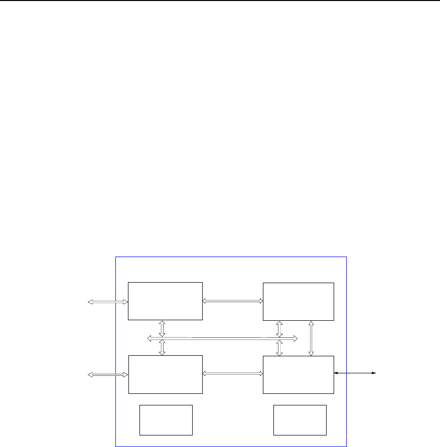
2.4.2 Structure and principle
The BCPM comprises the following parts as shown in Figure 2-4:
Multiplex/demultiplex
module
Baseband
processing
module
CPU module
Backplane
bus module
Power supply
module
BCPM
BASB
Control bus
Clock
module
BRDM Data bus
RS232 BCKM
High
speed
data bus
Data bus
Data bus
Figure 2-4 Structure of BCPM
I. Multiplex/demultiplex module
In forward direction, baseband data in the channel processing board are multiplexed
into high-speed signals and sent to radio side in the form of differential signals. In
reverse direction, the high-speed differential signals are demultiplexed and sent to
baseband processing chip.
II. Baseband processing module
The QUALCOMM new generation processing chip is used to perform forward and
reverse baseband data processing. With the help of in-board and inter-board data

Technical Manual
Airbridge BTS3612A CDMA Base Station System Principle
Chapter 2 Baseband Subsystem
2-9
daisy chains, channel processing capability is increased greatly. Maximally 6 sectors
can be supported.
III. CPU module
The high performance control CPU on BCPM mainly processes the forward & reverse
high-speed traffic data and control data and reports board status. At the network side,
the processing module receives control signaling, receives/transmits ATM cells and
communicates with BSC through BCIM. At the radio side, it controls the dedicated
baseband processing chip to generate orthogonal (IQ) data. After multiplexing, the data
pass BRDM as high-speed differential signals, to implement data exchange with radio
side.
IV. Backplane bus module
The BCPM communicates with other boards in the BTS baseband part through
backplane bus, including control information communication with BCKM and traffic data
communication with BCIM.
V. Clock module
The clock module performs double-frequency phase-locking to the clock signals from
the backplane, provides clock for boards, and drives and co-phases the clock signals
generated on the local board, to get satisfactory clock signals.
VI. Power supply module
The power supply module converts +24V input power into +3.3V for various modules of
local board.
2.4.3 External Interfaces
z High-speed data bus interface
Interface with BRDM.
z Backplane bus interface
Interface with other boards of baseband part
z Emergency serial port
Emergency serial port is an RS-232 serial port, works as a slave node and is used for
communicating with BCKM when other part of the board is faulty.
z Power supply interface
Led out from the power connector on the backplane, the interface is connected with
+24V power, +24V power ground and PGND.

Technical Manual
Airbridge BTS3612A CDMA Base Station System Principle
Chapter 2 Baseband Subsystem
2-10
2.4.4 Indices
z Power voltage: +24V.
z Power consumption <30W.
z Dimensions: 460mm%233.35mm (Length%Width)
2.5 BRDM
2.5.1 Overview
The BRDM is logically located between BTRM and BCPM, providing path for
orthogonal data connection (IQ) and exchange between the two so as to support the
flexible configuration relation between BCPM and BTRM. The BRDM also support
daisy chain cascading between BCPMs.
Data from the BTRM is sent to the BRDM through optical fibers. Then the BRDM
distributes the data before sending them to BCPMs via the high-speed data bus. With
the function of building cascades of daisy chain for BCPMs, the BRDM connects the
short daisy chain cascades to form standard daisy chain cascades of a certain length.
This facilitates the utilization of channel resource and flexible configuration of the
channel capacity of each sector carrier.
The BRDM has the following functions and features:
z Optical interfaces are configured to provide high-speed data paths to BTRM/
ODU3601C.
z Six pairs of high-speed data bus interfaces are provided to six BCPM slots through
the backplane.
z Flexible data distribution and exchange between BTRM/ODU3601C and BCPM
are enabled.
z Flexible data exchange between BCPMs is enabled. It can be cascaded to form
daisy chains, so BCPM resource pool can be achieved. The resource pool
improves the utilization ratio of channel resource and makes the configuration of
channel capacity of each sector carrier flexible.
z It exchanges O&M information with the BCKM through the backplane bus or
emergency serial port.
It forwards and receives O&M information of BTRM/ODU3601C via optical fibers and
provides O&M links between the baseband subrack and BTRM/ODU3601C.
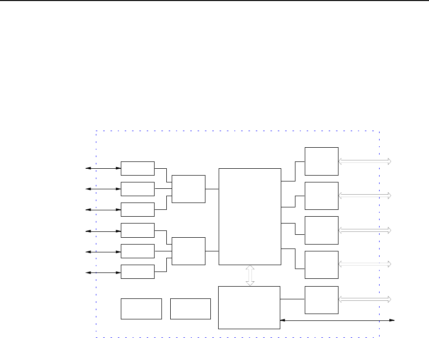
2.5.2 Structure and Principle
The BRDM has two specifications as follows:
Technical Manual
Airbridge BTS3612A CDMA Base Station System Principle
Chapter 2 Baseband Subsystem
2-11
z The BRDM configured with six pairs of multi-mode optical interfaces used to
connect to the BTRM.
z The BRDM with three pairs of single-mode optical interfaces used to cascade with
ODU3601C.
The two specifications differ in optical modules configured.
The structure of BRDM is shown in Figure 2-5.
Optical
module
High-speed
data
interface
Switching
module
CPU
module
Bus
interface
module
4 high-speed
data buses
Power supply
module
Optical
Optical
Optical
Optical
Optical
Optical
Clock
module
Optical
module
Optical
module
Optical
module
Optical
module
Optical
module
High-speed
data
interface
High-speed
data
interface
RS232
BTRM BCPM
Backplane
bus
BCKM
BCPM
BCPM
BCPM
BTRM
BTRM
BTRM
BTRM
BTRM
BRDM
High-speed
data
interface
High-speed
data
interface
High-speed
data
interface
4 high-speed
data buses
4 high-speed
data buses
4 high-speed
data buses
Figure 2-5 Structure of BRDM module (6 pairs of multi-mode optical interfaces)
The BRDM is composed of optical module, high-speed data interface module,
switching module, CPU module, bus interface module, power supply module and clock
module.
I. Optical module
The optical module converts optical signals into electrical signals. The BRDM can be
classified into single-mode BRDM and multi-mode BRDM according to different types
of optical module.
The multi-mode BRDM is equipped with six optical modules and provides six pairs of
optical interfaces. It is used to connect to the BTRM in the same BTS.
The single-mode BRDM is equipped with three optical modules and provides three
pairs of optical interfaces. It is used to cascade with ODU3601C.The single-mode
BRDM can be further classified into two kinds, namely 10km and 70km, according to
the transmission capability of the optical module.

Technical Manual
Airbridge BTS3612A CDMA Base Station System Principle
Chapter 2 Baseband Subsystem
2-12
II. High-speed data interface module
The high-speed data interface module converts rates of high-speed signals for the
convenient processing of the switching module.
III. Switching module
The switching module segments and paste data as required. It is a core processing
module of this board. Data from BTRM/ODU3601C are sent to this board, where the
switching module will distribute and paste them before sending them to the BCPM. The
switching module can also provide daisy chain cascading for the BCPMs through the
distribution and pasting of data.
IV. CPU module
The CPU module processes O&M information and configures switching parameters.
The O&M information from the BCKM is sent to this board via the bus interface module.
Then the CPU module processes the information and sends some specific O&M
information to the corresponding BTRM/ODU3601.
V. Bus interface module
This module provides the conversion of interfaces between the board and the
backplane, and provides a path for O&M information between this board and the
backplane.
VI. Clock module
The clock module performs double-frequency phase-locking to the clock signals from
the backplane. It provides clocks for boards, and drives and co-phases the clock
signals generated on the local board to get satisfactory clock signals.
VII. Power supply module
The power supply module converts +24V input power into +3.3V and 1.8V for various
modules of the local board.
2.5.3 External Interfaces
z Optical interface
There are two specifications of optical interface available according to optical modules:
6 pairs and 3 pairs. They connect to the BTRM and the ODU3601C respectively,
transmitting orthogonal (IQ) data and O&M information.
z High-speed data interface

Technical Manual
Airbridge BTS3612A CDMA Base Station System Principle
Chapter 2 Baseband Subsystem
2-13
The interfaces are connected with six traffic slots (BCPM slots) through the backplane,
for transmitting baseband orthogonal (IQ) data.
z Backplane bus interface
The interface is used for transmitting O&M information between BCKMs.
z Clock interface
The interface is connected with the BCKM via the backplane. It receives 2s, 16
%1.2288MHz clock signals and active/standby clock selection signal.
z Emergency serial port
Emergency serial port is an RS-232 serial port, works as a slave node and is used for
communicating with the BCKM when other parts of the board are faulty.
z Power supply interface
Led out from the power connector on the backplane, the interface is connected with
+24V power, +24V power ground and PGND.
2.5.4 Indices
z Power voltage: +24V.
z Power consumption <45W.
z Dimensions: 460mm%233.35mm (Length%Width)
2.6 BASB
2.6.1 Overview
The baseband backplane (BASB) is used to make interconnection of high-speed data
links among the boards of baseband part, and exchanges various management and
control information of boards with high-speed backplane technology.
Specifically, the backplane:
z Realizes interconnection of various signals between boards.
z Supports hot plug/unplug of all boards.
z Supports active/standby switchover of the BCKM.
z Leads in system power supply and distributes the power to all boards.
z Leads in signal monitoring lines for the fan subrack and the power subrack.
z Provides protection against misplugging.
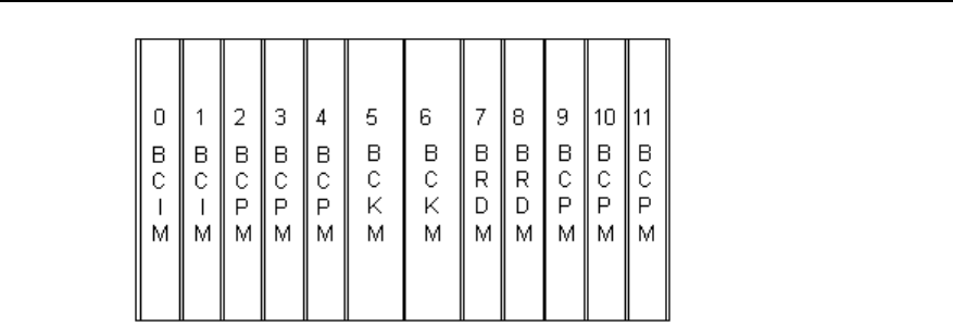
2.6.2 Structure and Principle
Functions of the slots in the BASB are as shown in Figure 2-6.
Technical Manual
Airbridge BTS3612A CDMA Base Station System Principle
Chapter 2 Baseband Subsystem
2-14
Figure 2-6 Functions of all slots in the BASB
A backplane includes two parts: connector and board slot.
The connector part includes 2 input connectors of backplane +24V power/ground, and
3 DB37 D-connectors. Power input connector, D-connector are all crimped devices.
The slots of the backplane are defined as follows:
z Slots 0~1 are for BCIMs.
z Sots 5~6 are for BCKMs.
z Slots 7~8 are for BRDMs.
z Slots 2~4, 9~11 are for BCPMs.
2.6.3 External Interfaces
The interfaces between the backplane and external devices include:
z System power interface
z Remote maintenance serial port
z Environment alarm interface
z Fan alarm serial port in baseband subrack
z System external synchronization interface
z Sixteen E1/T1 interfaces
2.6.4 Indices
z Dimensions: 368mm %262mm (Length%Width)
2.7 BESP
2.7.1 Overview
The E1 Surge Protector (BESP) is placed between the transmission equipment
subrack and the power supply subrack. It is a functional entity for the BTS to implement
Technical Manual
Airbridge BTS3612A CDMA Base Station System Principle
Chapter 2 Baseband Subsystem
2-15
lightning protection with E1/T1 trunk line. The 8 pairs of lightning protection units of the
BESP are used to discharge transient high voltage on the sheath and core of E1/T1
trunk line to the PGND.
2.7.2 Structure and Principle
I. Structure
The structure of BESP is shown in Figure 2-7.
8 E1s/T1s
4 E1s/T1s
4 E1s/T1s
Interface
DB37
BSC
Interface
DB25
Interface
DB25
BESP
...
BSC
BCIM
...
...
Level-1
protection
Level-2
protection
PGND
Level-1
protection
Level-2
protection
PGND
Level-1
protection
Level-2
protection
PGND
...
Figure 2-7 Structure of BESP
The board consists of three parts: DB25 connector, lightning protection unit and DB37
connector.
z Lightning protection unit
E1/T1 lightning protection unit has two inbound lines connected with DB25, two
outbound lines connected with DB37, and one PGND. Here PGNDs of all lightning
protection units can be interconnected.
z DB37 connector
The DB37 is a male connector, connected with eight E1/T1 cables.
z DB25 connector
Technical Manual
Airbridge BTS3612A CDMA Base Station System Principle
Chapter 2 Baseband Subsystem
2-16
The DB25 is a female connector. There are two DB25 connectors, respectively
connected with four E1/T1 cables.
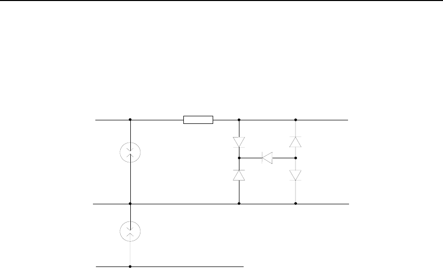
II. Principle of lightning protection
The principle of lightning protection is shown in Figure 2-8.
Core
Sheath
PGND
Lead in
DB25
Lead out
DB37
Figure 2-8 Principle of E1/T1 lightning protection
When the BTS E1 trunk line is struck by lightning, high voltage will arise first on the
DB25 and then spread to the lightning protection units. The lightning protection units
have two protection levels: air discharge tube and voltage limit mesh. The air discharge
tube discharges the high voltage to the ground and lowers it to 600V below. Then the
voltage limit mesh further lowers the voltage to 30V below.
2.7.3 External Interfaces
z E1/T1 interface
Interface with the BSC (DB25).
Connection with the BCIM (DB37)
2.7.4 Indices
z Bearable surge current: >10kA (common mode), >5KA (differential mode)
z Output residual voltage: <30V.
z Dimensions: 140mm %120mm (Length%Width)
Technical Manual
Airbridge BTS3612A CDMA Base Station System Principle
Chapter 2 Baseband Subsystem
2-17
2.8 BFAN
The fan module (BFAN) is installed right under the baseband subrack, serving as a part
of the blower type cooling system of the baseband subrack. The BFAN consists of fan
boxes and fan enclosures.
Each fan box contains four fan units (24V DC brush-free fan) and one BTS Fan Monitor
Module (BFMM). .
The fan enclosure is used for installation of fan boxes, whose outside is the BTS3612A
Fan Block Interface Board (BFIB) providing a system interface.
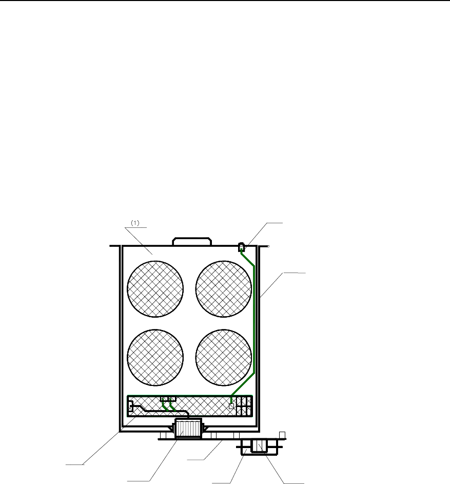
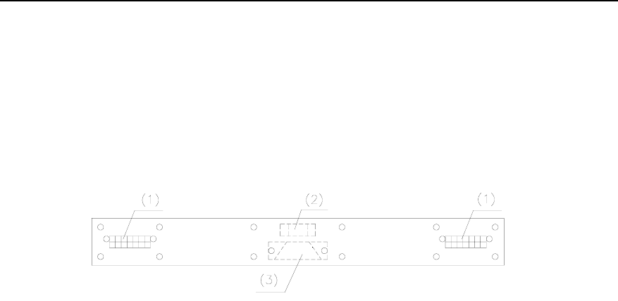
The structure of BFAN is shown in Figure 2-9.
(3)
(2)
(5)
(4)
(6)
(7)
(8)
(3)
(2)
(5)
(4)
(6)
(7)
(8)
(1) Fan box (2) LED indicator (3) Fan enclosure
(4) BFIB (5) System signal interface (6) Power input interface
(7) Blind mate connector (8) BFMM
Figure 2-9 Structure of BFAN
2.8.1 BFMM
I. Overview
Built in the fan box, the BTS Fan Monitor Module (BFMM) communicates with the
BCKM and receives instructions from the BCKM. It can make speed adjustment of the
PWM on the fan units and report board status information to the BCKM when it is
Technical Manual
Airbridge BTS3612A CDMA Base Station System Principle
Chapter 2 Baseband Subsystem
2-18
queried. It can also guarantee a safe and proper cooling system and lower the system
noise. Its main functions are as follows:
z Control rotating speed of the fans.
z Check whether fan units are in position and report their information.
z Check and report fan unit blocking alarm.
z Drive fan operating status indicator.
z Communicate with the Main Control Unit (MCU) of BCKM and report in-board
status information.
II. Structure and principle
The position of BFMM is shown in Figure 2-9. And its function is shown in Figure 2-10.
Main control unit
Power supply module
Temperature collection module
Communication module
Fan-in-position & fault
detection module
Fan drive module
Switch value alarm module
Indicator drive module
Figure 2-10 Functions of BFMM
z Power supply module
The power supply module converts +24V input power into the voltage required by
various modules of local board.
z Main Control Unit (MCU)
The MCU controls the fans and communicates with the BCKM. That is:
- Generates control PWM signals according to the instruction sent from the BCKM to
control the speed of fans.
- Detects fan alarm signal and in-board logic alarm signal, and reports them to the
BCKM.
- Generates panel indicator signals.
z Communication module
The module performs serial communication with the BCKM.
z Fan driving module

Technical Manual
Airbridge BTS3612A CDMA Base Station System Principle
Chapter 2 Baseband Subsystem
2-19
The PWM control signal generated in the MCU provides controlled power input for fans
by isolating driving circuits.
z Fan in position and fault detection module
This module isolates the fan-in-position signal and fan blocking alarm signal, then
converts them into logic level for the MCU to sample and analyze.
z Temperature collection module
The module collects the ambient temperature information of BFMM in real time, which
is realized by the MCU in query operation.
z Indicator driving module:
When a functional alarm (such as communication interruption in main control mode)
occurs to the board or a fan blocking alarm occurs to the motor, this module provides a
LED optical alarm interface inside the fan block, to drive the LED indicator on the fan
block front panel.
III. External interface
z Power interface
The interface is used to lead in working power for the BFMM.
z Communication serial port
Serial port communication ports 0 and 1 provide access for system active/standby
serial port. When the system has only one serial port, only port 0 is used.
z LED indicator driving output interface
This is the driving interface for LED status indicator on the panel of the fan box.
z Fan unit driving interface
Maximally six such interfaces are provided. They also serve as the interfaces for
fan-in-position detection and fan blocked detection.
IV. Indices
z Power voltage: +24V.
z Power consumption <5W.
z Dimensions: 280mm%35mm (Length%Width)
2.8.2 BFIB
I. Overview
The BTS Fan Block Interface Board (BFIB) provides electrical connection between fan
boxes and the system. On one hand, it provides blind mate interfaces for the fan boxes.
On the other hand, it provides the system with power interfaces and serial
communication interfaces.
Technical Manual
Airbridge BTS3612A CDMA Base Station System Principle
Chapter 2 Baseband Subsystem
2-20
II. Structure and principle
The position of BFIB is shown in Figure 2-9.
The BFIB implements interface conversion function. Refer to "3) Interface" for the
definition of interfaces.
Its structure is shown in Figure 2-11.
(1) MOLEX connector (2) Large 3PIN power socket (3) DB-15 signal socket
Figure 2-11 Illustration of BFIB structure
III. External interface
z Fan box electrical interface
Power supply ports and serial port communication ports are provided for the fan boxes
through MOLEX connectors.
z System power supply interface
The interface leads in the system power through big 3-pin connectors.
z System serial communication interface
External serial communication interface is provided through the DB-15.
IV. Indices
Dimensions: 230mm%30mm (Length%Width)
Technical Manual
Airbridge BTS3612A CDMA Base Station System Principle
Chapter 3 Radio Frequency Subsystem
3-1
Chapter 3 Radio Frequency Subsystem
3.1 Overview
3.1.1 Radio Frequency Subsystem Functional Structure
The structure of RF (radio frequency) subsystem is shown in Figure 3-1.
CDU
RLDU
BHPA
BHPA
BTRM
BTRM
Antenna & feeder
BRDM
BRDM
BRDM: BTS Resource Distribution Module BTRM: BTS Transceiver Module
BHPA: BTS High Power Amplifier Unit CDU: Combining Duplexer Unit
RLDU: Receive LNA Distribution Unit
Figure 3-1 Structure of RF subsystem
Note:
The above figure illustrates the duplexer configuration for 800MHz band. For 800MHz band, the duplexer
can also be DDU. For 450MHz band, the duplexer can be DFU, DDU or CDU. For 1900MHz band, the
duplexer can be DDU or CDU.
The RF subsystem is connected with the BCIM of the baseband subsystem via the
optical interface provided by the BTRM, and connected with the antenna & feeder
subsystem via the feeder interface provided by a CDU, DDU, or DFU. It implements the
following functions:

Technical Manual
Airbridge BTS3612A CDMA Base Station System Principle
Chapter 3 Radio Frequency Subsystem
3-2
In forward link, it performs power adjustable up-conversion and linear power
amplification to the modulated transmission signals, filtering the transmission signals to
meet the corresponding air interface standard.
In reverse link, it filters the signals received by the BTS antenna to suppress out-band
interference, and then performs low-noise amplification, noise factor adjustable
frequency down-conversion, and channel selective filtering.
3.1.2 Introduction to RF Modules
The RF subsystem is composed of RF modules. Figure 8-3 shows the RF subsystem in
full configuration.
RF modules include:
z BTRM: Complete the modulation/demodulation of baseband signal and up/down
conversion.
z BHPA: Complete the high-power linear amplification of transmitting carrier signals.
z DFU: Complete the wave filtering and duplex isolation of one main
transmitting/receiving signal, and the wave filtering of diversity receiving signal. It
is one of the RF front-end modules.
z DDU: Complete the isolation and duplex filtering of two receiving/transmitting
signals. It is one of the RF front-end modules and is not equipped with the
combiner function.
z CDU: Complete the combination and wave filtering of two transmitting signals,
duplex isolation of main transmitting and receiving signals, and the wave filtering
of diversity receiving signal. It is one of the RF front-end modules.
z RLDU: Complete the low noise amplification and dividing of receiving signals.
Besides the above modules, the backplane of RF module and the RF fan module will
also be introduced in this chapter.
3.2 BTRM
3.2.1 Overview
In reverse link, the BTS Transceiver Module (BTRM) receives the main/diversity RF
signals from the RLDU, and then changes the RF signals into baseband signals
through down-conversion, wave filtering and multiplexing. Finally the BTRM sends the
baseband signals to the baseband subsystem through the BRDM.
In forward link, the BTRM receives the baseband signals from the BRDM, then
changes the baseband signals into RF signals through de-multiplexing, wave filtering
and up-conversion. Finally the BTRM sends the RF signals to the RF subsystem
through the RF front module such as CDU.
Technical Manual
Airbridge BTS3612A CDMA Base Station System Principle
Chapter 3 Radio Frequency Subsystem
3-3
The BTRM also receives the management and configuration information from the
BCKM, and reports the status and alarms of itself to the BCKM.
3.2.2 Structure and Principle
The BTRM consists of BTS Intermediate Frequency Module (BIFM) and BTS Radio
up-down Converter Module (BRCM). Its structure is shown in Figure 3-2.
FIR
&
DAGC
DAC
Demultiplexer/multiplexer
ADC
Power
CPU Clock
Optical interface
Down
converter ADC Filter
BHPA
Local oscillator
BRCM
RLDU
BIFM
RLDU
BRDM
+24V
Main receiver
Diversity receiver
Transmitter
BHPA
PSU
Filter
Filter
Down
converter
Up
converter
FIR
&
DAGC
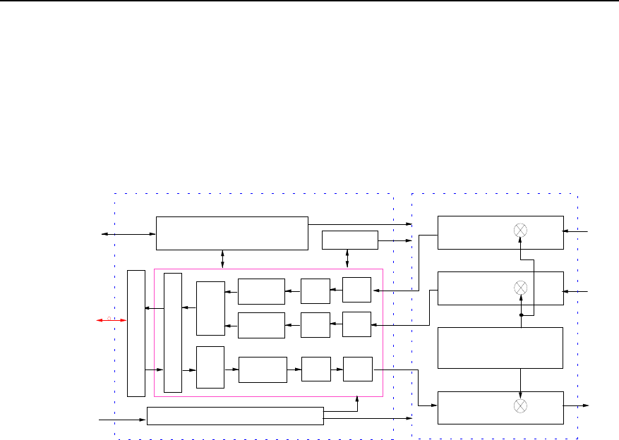
Figure 3-2 Structure of BTRM
I. BIFM
The BIFM consists of up-converter, down-converter, multiplexer/demultiplexer, optical
interface, clock, CPU, and power supply sub-unit. It is in charge of the conversion
between the analog intermediate frequency signal and the digital baseband signal, and
the control of the BTRM. The functions of each sub-unit are as below:
z Up-converter
The up-converter accomplishes the wave filtering, digital up-conversion and
digital-analog conversion of the signals in the transmit path.
On receiving the baseband I/Q signals that have been de-multiplexed, the up-converter
performs digital up-conversion after baseband filtering. Then the digital intermediate
frequency signals are converted into analog intermediate frequency signals after
digital-analog conversion and wave filtering. At last, the analog intermediate frequency
signals are sent to the transmitter in BRCM via radio frequency (RF) interface.
z Down-converter
The down-converter accomplishes the analog-digital conversion, digital
down-conversion and baseband filtering of the signals in the receive path.

Technical Manual
Airbridge BTS3612A CDMA Base Station System Principle
Chapter 3 Radio Frequency Subsystem
3-4
On receiving the analog intermediate frequency signals via the radio interface, the
down-converter converts them into digital intermediate frequency signals via
analog-digital conversion. Then the digital intermediate frequency signals are
converted into baseband I/Q signals via digital down-conversion and baseband filtering.
As last, the I/Q signals are transmitted to the demultiplexer/multiplexer.
z Demultiplexer/multiplexer
Under the control of the CPU, the demultiplexer/multiplexer de-multiplexes the forward
I/Q signals, and multiplexes the reverse I/Q signals. At the same time, it
multiplexes/de-multiplexes the operation & maintenance (O&M) signals of the OML.
z Optical interface
The optical interface performs channel coding and decoding, and accomplishes
optical-electrical signal conversion and electrical-optical signal conversion. It is the
interface between the BIFU and the BRDM of the upper-level BTS, and the interface
between the BIFU and the MTRM (Micro-bts Transceiver Module) in the lower-level
SoftSite.
z Clock
The clock generates all the clock signals needed by the BIFU, which include the clocks
for up/down conversion, analog-digital conversion (ADC), and digital-analog
conversion (DAC), as well as other working clocks. It also provides the reference clock
for the BRCM.
z CPU
The CPU is in charge of the control of BTRM, which includes the initialization upon
power-on, alarm collecting and reporting, and processing operation & maintenance
related messages.
z Power supply
With input voltage of +24V, the power supply sub-unit provides power supply to BIFU
and BRCU.
II. BRCM
The BRCM consists of transmitter, main/diversity receiver and local oscillator. It
up-converts, amplifies the intermediate frequency signals output by BIFM, and
performs spuriousness-suppression wave filtering. It also performs analog
down-conversion, amplification of BTS main/diversity receiving signal input from the
RLDU, and channel-selection wave filtering. The functions of each sub-unit are as
below.
z Transmitter
When receiving the modulated analog intermediate frequency signals output by BIFM,
the transmitter converts them to specified RF band via two times of up-conversions.
Before and after the up-conversion, wave filtering, signal amplification and power

Technical Manual
Airbridge BTS3612A CDMA Base Station System Principle
Chapter 3 Radio Frequency Subsystem
3-5
control are performed, so as to ensure the RF signals output meet the protocol
requirements on power level, Adjacent Channel Power Radio (ACPR) and
spuriousness.
z Main/diversity receiver
The main/diversity receiver converts the RF signals output by RLDU to specified
intermediate frequency signals via down-conversion, and performs wave filtering,
signal amplification and power control before/after the down-conversion, so as to
ensure the intermediate frequency signals output can be received by BIFM.
z Local oscillator
The local oscillator consists of intermediate frequency source, transmit RF synthesizer
and receive RF synthesizer.
The intermediate frequency source generates the local oscillator signals for
intermediate frequency up conversion in transmit path.
The transmit RF synthesizer generates the local oscillator signals for the up-conversion
of the transmit path.
The receive RF synthesizer generates the local oscillator signals for the down
conversion of main/diversity receive path.
3.2.3 External Interfaces
There are interfaces between the BTRM and the BHPA/RLDU/BRDM/PSU. The
descriptions of each interface are given as below:
z RF interface between the BTRM and the BHPA
The RF transmitting signal is output via this interface to BHPA, where the signal is
amplified and then outputted.
z RS485 interface between the BTRM and the BHPA
This interface is used to transfer alarm and control signal, and power detection signal.
z RF interface between the BTRM and the RLDU
The main/diversity RF receiving signal output by RLDU is received via this interface.
z Optical interface between the BTRM and the BRDM
Baseband data are transmitted or received via this interface.
z Power supply interface
Interface with BTS3612A TRx Backplane (BTRB), This interface is used to provide
+24V power supply to BTRM.

Technical Manual
Airbridge BTS3612A CDMA Base Station System Principle
Chapter 3 Radio Frequency Subsystem
3-6
3.2.4 Indices
z Supported frequency band: 450MHz, 800MHz and 1900MHz
z Power voltage: +24V
z Power consumption: 51W
z Dimensions: 460mm % 233.5mm % 64mm (Length % Width % Depth)
Note:
BTRM supports the different frequency bands with different BTRM types, such as BTRM for 450MHz band,
BTRM for 800MHz band, BTRM for 1900MHz band. And this principle also applies to the other RF
modules including BHPA, CDU, DFU, DDU, and RLDU.
3.3 BHPA
3.3.1 Overview
Located at the left side of the BTRM, the BTS High Power Amplifier Module (BHPA)
amplifies the RF modulation signals output by BTRM. Its main functions are:
z RF power amplification: The BHPA performs power amplification for the RF
modulation signals from BTRM.
z Over-temperature alarm: When the temperature of power amplifier base board
exceeds a specified threshold, the BBFM will process the over-temperature alarm
signal generated by HPAU and report it to BTRM.
z Over-excited alarm: When the power level of BHPA input RF signal exceeds a
specified threshold, the BBFM will process the over-excited alarm signal
generated by HPAU and report it to BTRM.
z Gain decrease alarm: When the gain of the power amplifier drops over 6dB, the
BBFM will process the gain decrease alarm signal generated by HPAU and report
it to BTRM.
z Fan monitoring: The BBFM installed in BHPA performs such functions as fan
alarm and power amplifier alarm signal processing & reporting, and fan speed
adjustment.
3.3.2 Structure and Principle
The structure of BHPA module includes the following parts, as shown in Figure 3-3:
Technical Manual
Airbridge BTS3612A CDMA Base Station System Principle
Chapter 3 Radio Frequency Subsystem
3-7
RF input
Coupler
Power
amplification
RF output
BTRB
CDU
BTRM
BBFM
BDCS
Sampling
port
+24V
BHPA
Alarm signal
Alarm signal
Alarm
circuit
BTRM
Circulator
HPAUz
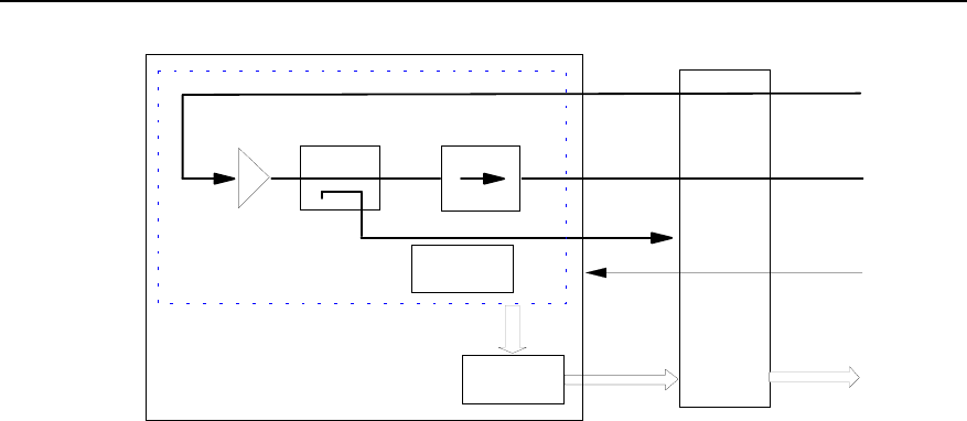
Figure 3-3 Functional structure of BHPA module
I. HPAU
The High Power Amplifier Unit (HPAU) consists of two parts: power amplifier and alarm
circuit.
The power amplifier amplifies the RF signals from BTRM. The amplified RF signals are
then sent to CDU or DFU via BTRB.
The alarm circuit monitors the power amplifier status and generates over-temperature
alarm, over-excited alarm and gain decrease alarm signals when necessary. The alarm
signals will be sent to BBFM, where they will be processed and reported to BTRB.
The coupler is used to couple the RF output signals to the sampling port for test
purpose.
The output power of HPAU can be adjusted by controlling the RF output signal of
BTRM.
II. BBFM
The BTS BTRM Fan Monitor (BBFM) processes fan alarm signals and power amplifier
alarm signals, and sends them to BTRM via BTRB, and then BTRM will report them to
upper level. BBFM can adjust the fan speed based on the ambient temperature and the
actual BHPA output power in order to lower the noise of fans.
For the detail of BBFM, see “3.9 BRFM”

Technical Manual
Airbridge BTS3612A CDMA Base Station System Principle
Chapter 3 Radio Frequency Subsystem
3-8
3.3.3 External Interfaces
External interfaces of the BHPA module are D-type combination blind mate connectors,
including:
z RF interface
The RF interface of BHPA has one input port and one output port. They are connected
respectively with BTRM RF output port via BTRB and CDU/DFU/DDU RF input port via
coaxial cable.
z Power supply interface
Interface with BTS3612A TRx Backplane (BTRB), This interface is used to provide
+24V power supply to BTRM.
The +24V power is supplied with the BTS Direct Current Switch box (BDCS).
z Alarm interface
Interface with BTRM. Fan alarm signals and power amplifier alarm signals are sent via
BTRB to BTRM.
3.3.4 Indices
z Supported frequency band: 450MHz, 800MHz, and 1900MHz
z Power supply: +24V
z Power consumption: <380W
z Dimensions: 460mm %233.5mm %64mm (Length % Width % Depth)
3.4 BTRB
3.4.1 Overview
The BTS3612A TRx Backplane (BTRB) accomplishes the following functions:
z Fastening the connection between BTRM and BHPA.
z Fastening the RLDU.
z Monitoring BHPA temperature.
z Providing alarm signal interface between BTRM and RLDU.
Key internal parts of BTRB include connectors and temperature sensors.
3.4.2 Structure and Principle
The BTRB structure is as shown in Figure 3-4.
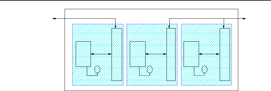
Technical Manual
Airbridge BTS3612A CDMA Base Station System Principle
Chapter 3 Radio Frequency Subsystem
3-9
RS485 RS485
RLDU0
RS485
RS485
RLDU1
Temperature
Sensor Temperature
Sensor Temperature
Sensor
2mmHM A/N
connnector
24W7
connnector
2mmHM A/N
connnector
24W7
connnector
2mmHM A/N
connnector
24W7
connnector
Functional
group 0 Functional
group 1 Functional
group 2
Figure 3-4 Functional structure of BTRB
I. BTRM 2mm connector
Each set of 2mm connectors includes one 5%22pin A-connector and three 3-socket-
C4-connectors.
A-connector transfers RLDU alarm signals from DB9 connector and RS485 interface
message from BHPA 24W7 combination DB-connector.
C4-connector transfers the main/diversity input/output RF signal of BTRM and +24V
DC power signal needed by BTRM.
II. BHPA 24W7 D-type combination blind mate connector
Each 24W7 D-type combination blind mate connector includes two coaxial contacts
(transferring BHPA input/output RF signals), two high-current power contacts
(transferring +24V power supply and PGND signals), one set of RS485 signal contacts
and a group of contacts for temperature sensor signals.
III. DB9 connector
There are two angled DB9 connectors on BTRB for two RLDUs alarm signals
transferred to BTRM.
IV. Temperature sensor
There are three temperature sensors for the three BHPA slots, used for sensing the air
temperature at each BHPA air outlet. They will convert the information into current and
send to BFMM on BHPA for processing. In this way, fan speed can be controlled on a
real-time basis.
3.4.3 External Interfaces
See the introduction to connectors in Section 3.4.2.
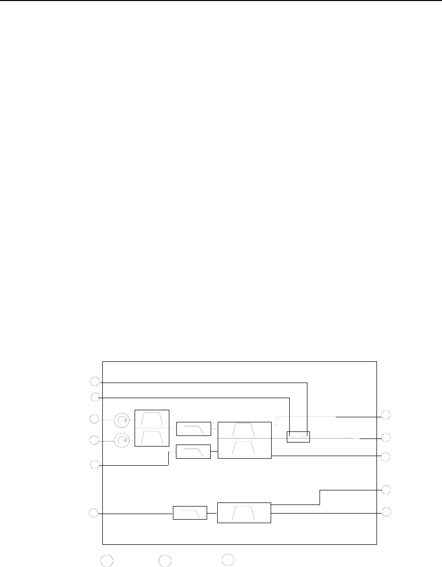
Technical Manual
Airbridge BTS3612A CDMA Base Station System Principle
Chapter 3 Radio Frequency Subsystem
3-10
3.4.4 Indices
Dimensions: 664mm%262mm%3mm (Length % Width % Depth)
3.5 CDU
3.5.1 Overview
The Combining Duplexer Unit (CDU) accomplishes the following functions:
z Combining two carrier signals from the two BHPAs into one.
z Isolating and filtering the receiving and transmitting signals.
z Filtering the transmitting signals so as to suppress BTS spurious emissions.
z Filtering the receiving signals so as to suppress the interference from outside the
receive band.
Key internal parts of CDU include isolator, 2-in-1 combiner, duplexer, filter and
directional coupler.
3.5.2 Structure and Principle
CDU structure is as shown in Figure 3-5.
N
D-SUB S
DN-Type SMA-Type
LPF
LPF BPF
DUPLEXER
COUPLER
FILTER COMB.
N
N
S
S
S
D
D
D
D
D
D
TX-TEST
TX/RXM-ANT
RXD-ANT
RXM-TEST
RXD-TEST
TX1
Pf-OUT
Pr-OUT
TX2
RXM-OUT
RXD-OUT
LPF
ISOLATOR
LPF: Low Pass Filter BPF: Band Pass Filter
Figure 3-5 Structure of CDU

Technical Manual
Airbridge BTS3612A CDMA Base Station System Principle
Chapter 3 Radio Frequency Subsystem
3-11
I. Isolator
There are two isolators at each input port of the combiner in CDU. They are used to
isolate the two carriers from two input ports.
II. Combiner
The combiner is a narrow band cavity filtering combiner. In comparison with broadband
combiner, it features lower insertion loss and effective isolation.
III. Duplexer
The duplexer is used to isolate transmitted signals and received signals, suppress
transmission spurious and reduce antenna quantity.
IV. Filter
The filter on the transmitting channel filters transmitting signal.
The filter on the main/diversity receive channel filters main/diversity receive signals
respectively. Then it sends them to low-noise amplifier in the RLDU for amplification.
V. Directional coupler
The directional coupler couples forward/reverse power to RLDU, and monitors the
antenna VSWR.
3.5.3 External Interfaces
The CDU is a module shared by the transmit and receive paths of the BTS. Therefore,
it has interfaces with other modules both in the transmitting and in the receiving paths.
Its external interfaces include a set of 8W8 D-type combination blind mate connectors
on the backside, and a set of N-connectors and SMA connectors on the front side. The
interface signals include:
z RF signals between CDU combiner input ports and BHPA output ports. They are
transferred through the blind mate connectors on the backside.
z BTS receiving signals output from the duplexer. They are sent to RLDU via the
blind mate connector on the backside.
z BTS transmitting signals, which are transferred to the cabinet-bottom antenna
interface through the RF cable connected with the N-connector at the front side of
CDU.
z BTS receiving signals, which are transferred from the cabinet-bottom antenna
interface through the RF cable connected with the N-connector on the front side of
CDU.
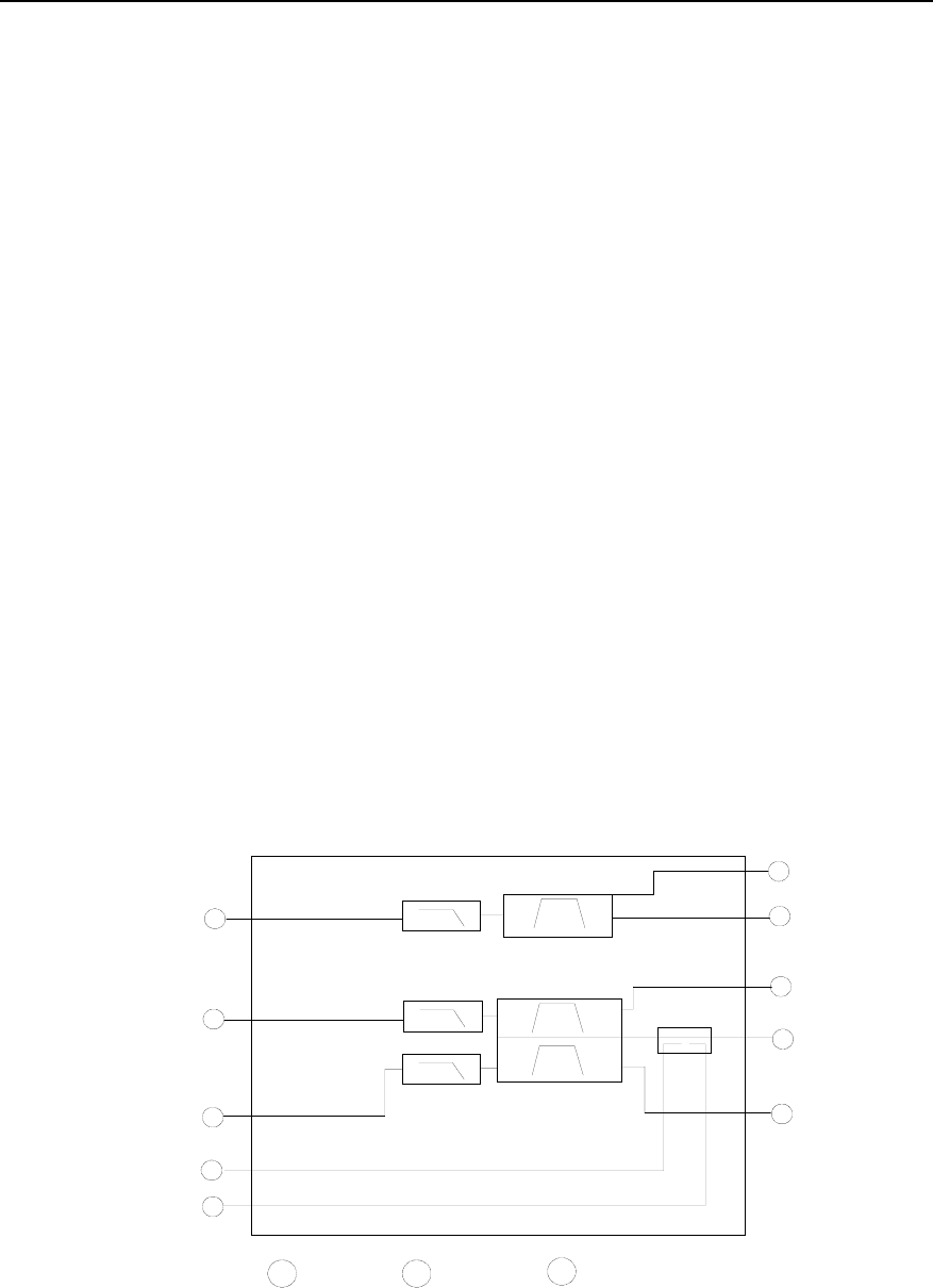
Technical Manual
Airbridge BTS3612A CDMA Base Station System Principle
Chapter 3 Radio Frequency Subsystem
3-12
z Forward/reverse coupled RF signals, which are sent to RLDU via the blind mate
connector on the backside.
z Forward/reverse coupled test signals, which are output through the standard SMA
connector on the front side of CDU.
3.5.4 Indices
z Number of combined signals: 2
z Supported frequency band: 450MHz, 800MHz, and 1900MHz.
Module dimensions: 450mm%100mm%344.8mm (Length % Width % Depth)
3.6 DFU
3.6.1 Overview
The Duplexer Filter Unit (DFU) accomplishes the following functions:
z Isolating and filtering the transmitting and receiving signals for the single carrier.
z Filtering the diversity receiving signals so as to suppress out-band interference.
Key parts of DFU include low-pass filter, duplexer, filter and directional coupler.
3.6.2 Structure and Principle
The DFU structure is shown in Figure 3-6.
N
D-SUB S
DN-Type SMA-Type
LPF
DUPLEXER
COUPLER
N
S
S
D
D
D
D
TX-TEST
TX/RXM-ANT
RXM-TEST
Pf-OUT
Pr-OUT
TX
RXM-OUT
LPF
LPF
D
RXD-OUT NTX/RXD-ANT
SRXD-TEST
BPF
LPF: Low Pass Filter BPF: Band Pass Filter
Figure 3-6 Structure of DFU

Technical Manual
Airbridge BTS3612A CDMA Base Station System Principle
Chapter 3 Radio Frequency Subsystem
3-13
I. Filter
The filter on the transmitting channel filters transmitting signal.
The filter on the main/diversity receive channel filters main/diversity receive signals
respectively. Then it sends them to low noise amplifier in the RLDU for amplification.
II. Duplexer
The duplexer is used to isolate transmitting and receiving signals, suppress
transmission spurious and reduce antenna quantity.
III. Directional coupler
The directional coupler couples forward/reverse power for RLDU, and monitors the
antenna VSWR.
3.6.3 External Interfaces
DFU is a module shared by the transmit and receive paths of the BTS. Therefore, it has
interfaces with other modules in both the transmit and receive paths.
Its external interfaces include a set of 8W8 D-type combination blind mate connectors
on the backside, and a set of N connectors and SMA connectors on the front side. The
interface signals include:
z The signals between DFU and BHPA, which are transferred through the blind
mate connectors on the backside.
z BTS transmitting signals, which are transferred to the cabinet-bottom antenna
interface through the RF cable connected with the N-connector at the front side of
the module.
z BTS receiving signals, which are transferred from the cabinet-bottom antenna
interface to DFU for filtering through the RF cable connected with the N-connector
on the front side of the module.
z BTS receiving signals output from the duplexer and diversity receive filter. They
are sent to RLDU via the blind mate connector on the backside.
z Forward/reverse coupled RF signals, which are sent to RLDU via the blind mate
connectors on the backside.
z Forward/reverse coupled test signals, which are output through the standard SMA
connector on the front side.
3.6.4 Indices
z Supported frequency band: 450MHz
z Module dimensions: 450mm%100mm%344.8mm (Length % Width % Depth)
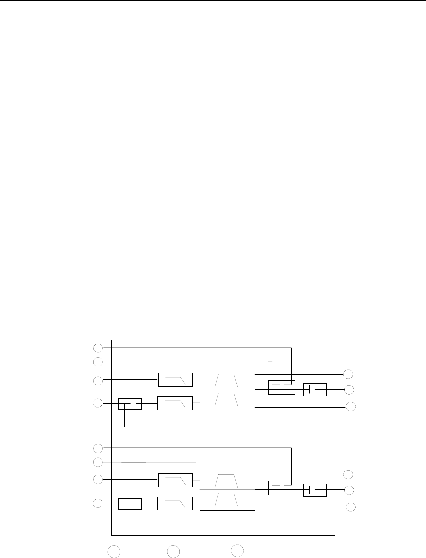
Technical Manual
Airbridge BTS3612A CDMA Base Station System Principle
Chapter 3 Radio Frequency Subsystem
3-14
3.7 DDU
3.7.1 Overview
The Dual Duplexer Unit (DDU) implements the following functions:
z Isolation and low-pass filtering of two receiving and transmitting signals.
z Providing two DC feeds to T-type Tower Mounted Amplifier (TMA).
z Voltage Standing Wave Ratio (VSWR) test on transmit channels in both forward
and backward directions.
z Coupling test of transmitting and receiving signals.
Key components within DDU include low-pass filter, duplexer, directional coupler, and
BIAS T (DC supply unit for TMA) which is optional.
3.7.2 Structure and Principle
There are two types of DDU, type A with the BIAS T, type B without the BIAS T. Type A
can be selected to feeder DC to the TMA which may be used when the BTS operates at
1900MHz band.
The DDU (with the BIAS T) structure is shown in Figure 3-7.
N
D-SUB S
DN-Type SMA-Type
LPF DUPLEXER
COUPLER
N
S
S
D
D
D
D
TX2-TEST
TX/RXD-ANT
RXD-TEST
Pf2-OUT
Pr2-OUT
TX2
RXD-OUT
LPF
LPF
DUPLEXER
COUPLER N
S
S
D
D
D
D
TX1-TEST
TX/RXM-ANT
RXM-TEST
Pf1-OUT
Pr1-OUT
TX1
RXM-OUT
LPF
BIAS T
BIAS T
BIAS T
BIAS T
LPF: Low-pass Filter
Figure 3-7 Structure of DDU

Technical Manual
Airbridge BTS3612A CDMA Base Station System Principle
Chapter 3 Radio Frequency Subsystem
3-15
I. Low-pass filter
The low-pass filter is used to suppress the high-order harmonic wave. The low-pass
filter on receive channel also functions to suppress the interference from the transmit
channel.
II. Duplexer
The duplexer is used to isolate both transmitting and receiving signals, suppress
spurious emission and save antennae.
III. Directional coupler
The bi-directional coupler couples forward and reverse power for RLDU, and monitors
the antenna VSWR.
IV. DC supply unit for TMA (BIAS T)
If the BTS is applied to 1900MHz band, a TMA may be used. The BIAS T of the DDU is
to combine and divide RF signals and DC feed so as to provide the TMA with DC.
3.7.3 External Interfaces
The DDU is a module shared by both the transmitting and receiving paths of the BTS. It
provides interfaces with other modules both in the transmitting and receiving paths. Its
external interfaces include a set of 8W8 DB combination blind mate connectors on the
back, and a set of N-connectors and the SMA connectors in the front. The interface
signals include:
z Signals between transmit input port and the BHPA interface. They are transmitted
through the blind mate connectors on the back.
z Transmitting signals, which are transmitted to the cabinet-bottom antenna port
through the RF cable connected with the N-connector in front of the DDU.
z Receiving input signals, which are transmitted from the cabinet-bottom antenna
port through the RF cable connected with the N-connector in front of the DDU.
z Signals output from the receive filter. They are sent to the RLDU via the blind mate
connector on the back.
z Transmitting forward and reverse coupled RF signals, which are sent to the RLDU
via the blind mate connector on the back.
z Transmitting and receiving coupled test signals, which are outputted through the
standard SMA connector in front of the DDU.
3.7.4 Indices
z Supported band: 800MHz, and 1900MHz
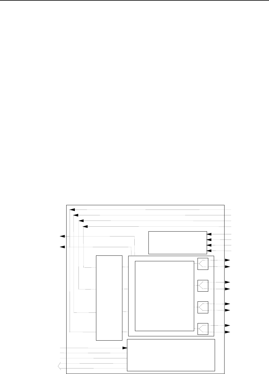
Technical Manual
Airbridge BTS3612A CDMA Base Station System Principle
Chapter 3 Radio Frequency Subsystem
3-16
z Module dimensions: 450mm%100mm%344.8mm (Length%Width%Depth)
3.8 RLDU
3.8.1 Overview
The Receive LNA Distribution Unit (RLDU) consists of Low Noise Amplifier (LNA),
distribution unit, configuration switch and alarm monitoring circuit. Its main functions
are:
z Low noise amplification and distribution for BTS main/diversity receiving signals.
z Built-in electronic RF switch supporting multiple BTS configurations (3 sectors or 6
sectors).
z Antenna VSWR monitoring and alarming, BTS forward RF power detecting, LNA
running status monitoring and alarming.
3.8.2 Structure and Principle
The RLDU structure is shown in Figure 3-8.
VSWR check processing
VSWR and power
check
LNA
module
Switch distribution
module
DC-IN
PWR
S/W
DB15
RXAM-TEST
RXBM-TEST
RXBD-IN
RXBM-IN
RXAD-IN
RXAM-IN
APf-IN
APr-IN
BPf-IN
BPr-IN
RXAM1
RXAM2
RXAD1
RXAD2
RXAM3/RXBM1
RXAM4/RXBM2
RXAD3/RXBD1
RXAD4/RXBD2
Power supply
Forward power output
Figure 3-8 Structure of RLDU

Technical Manual
Airbridge BTS3612A CDMA Base Station System Principle
Chapter 3 Radio Frequency Subsystem
3-17
I. Receiving signal low noise amplification and distribution unit
There are 4 LNAs and distributors inside the RLDU, which process 4 signals. The 4
LNAs have the same specifications such as gain, noise factor and dynamic to ensure
the balance among 4 receive paths.
II. Configuration switch unit
The electronic switches inside the RLDU are designed for supporting different BTS
configurations. When the BTS is configured in the 3-sector mode, the electronic
switches can be set to make the RLDU operate in the single-sector mode that has two
main/diversity receiving paths (Each path provides 1-in-4 output to support 1~4 carriers
configuration for each sector). When the BTS is configured in the 6-sector mode, the
electronic switches can be set to make the LDU operate in the 2-sector mode. And
each sector provides 4 main/diversity receive paths (Each path provides 1-in-2 output,
supporting 1~2 carriers configuration in each sector).
III. Antenna VSWR and LNA status monitoring unit
The transmitted forward/reverse power coupling signals from the CDU or the DFU or
the DDU are processed in the antenna VSWR monitoring circuit inside the RLDU.
When the VSWR of transmitting antenna exceeds a specified threshold, alarm will
occur. At the same time, the RLDU also converts transmit coupling power signal into
DC level signal through its RF power detecting circuits. Through this DC level signal,
any exception of transmit signal power of antenna can be monitored in realtime. LNA
status monitoring circuit monitors the voltage and current of the 4 LNAs inside the
RLDU. It generates alarm when fault t is found.
3.8.3 External Interfaces
RLDU is the reverse link function module of the BTS, which interfaces with CDU/DFU
and BTRM in both input and output sides through the two sets of 8W8 D-type
combination blind mate connectors on the back of the module.
Interface signals between the RLDU and the CDU/DFU/DDU are:
z Main/diversity path receiving RF signals outputted from two CDU/DFU/DDU
receive filters. They are amplified and distributed by the RLDU.
z The CDU/DFU/DDU coupling RF signals, which are used for antenna VSWR
monitoring and forward power detection.
Interface signals between the RLDU and the BTRM are:
z Main/diversity path receiving RF signals transmitted to the BTRM after being
amplified and distributed.

Technical Manual
Airbridge BTS3612A CDMA Base Station System Principle
Chapter 3 Radio Frequency Subsystem
3-18
z Antenna VSWR, the LNA status monitoring alarm signals and forward power
detection voltage signals, which are outputted to the BRCM by the RLDU through
a DB15 interface in front of the module and transmitted to the BIFM for processing.
The +24V DC power is necessary for the RLDU. It is provided directly by the secondary
power supply module in the BTS through a MOLEX power connector in front of the
module.
3.8.4 Indices
z Supported frequency band: 450MHz band, 800MHz band, and 1900MHz band
z Power supply: +24VDC
z Power consumption: <50W
z Module dimensions: 450mm%180mm%50mm (Length%Width%Depth)
3.9 BRFM
The BTS RF Fan Module (BRFM) mainly consists of the BBFM, the BBFL and fans.
The following is the introduction to the BBFM and the BBFL.
3.9.1 BBFM
I. Overview
The BTS BTRM FAN Monitor (BBFM) collects and analyzes the temperature
information of BHPA module and adjusts the fan speed in realtime to lower the system
noise, so as to prolong equipment service life and improve the external performance of
the overall system on the premise that the system works in a safe thermal status.
The Pulse Wide Modulation (PWM) control signal regarding the fan speed can be
generated by the MCU of the local board or configured by the control unit of the BTRM
module. At the same time, the BBFM reports to the BCKM the gain decrease,
over-temperature, over-excited alarm and fan failure alarm of the BHPA to ensure the
reliability of the BHPA module. Specifically, it functions to:
z Control fan speed, monitor and report fan alarm.
z Monitor and report the BHPA alarm.
z Drive fan monitor indicator module.
z Collect temperature information of the BHPA module.
z Communicate with the BTRM module.
II. Structure and principle
The position of the BBFM in the BHPA module is as shown in Figure 3-9.
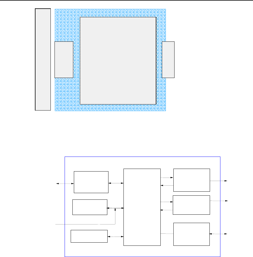
Technical Manual
Airbridge BTS3612A CDMA Base Station System Principle
Chapter 3 Radio Frequency Subsystem
3-19
Fan cover
BHPA
BBFM
Blind mate
connector
Figure 3-9 Position of BBFM in BHPA module
The structure of the BBFM is shown in Figure 3-10.
MCU
Communication
interface
Watchdog
HPAU
Interface
circuit
PWM
Modulation
circuit
Panel indicator
driving alarm
signal isolation
circuit
Temperature
collection
Serial port
BBFM
BHPA
External
temperature
collection
Fan cover
BTRM
Figure 3-10 Structure of BBFM module
z MCU module
The MCU module implements the following functions:
- Collect and analyze the temperature information to generate PWM signals for
controlling the fan speed.
- Receive alarm signals generated by the BHPA module and fan alarm signals and
report to the BTRM module.
- Generate panel indicator signal.
- Communicate with the BTRM module.
z BHPA interface module

Technical Manual
Airbridge BTS3612A CDMA Base Station System Principle
Chapter 3 Radio Frequency Subsystem
3-20
This module isolates and drives the interface with the BHPA.
z Temperature information collection module
This module collects the temperature information of the BHPA module in real time,
which is implemented by the MCU in query mode.
z Panel indicator driving and alarm signal isolation module
This module is used to drive the panel indicator and isolate fan alarm signals.
z Communication module
The communication module performs serial communication with the BTRM module.
z Power supply module
The input power of the BFMM is +24V, and power consumption is 3.5W (excluding
power for the fans).
III. External interfaces
z BHPA interface
Interface with the BHPA module, used for the BHPA alarm monitoring.
z Serial communication interface
Interface used to report the alarm of the fans and the BHPA module.
z Interface with the fan cover
Including fan alarm signal, panel indicator, and fan power interface.
IV. Indices
Module dimensions: 200.0mm%55.0mm (Length%Width).
3.9.2 BBFL
I. Overview
The BTS BTRM FAN Lamp Module (BBFL) has three RUN indicators to indicate the
running status of the BTRM module, fans and the BHPA module. The board is
connected with the BBFM via the fan cover interface. It is an auxiliary board.
II. Structure and principle
The structure of the BBFL is shown in Figure 3-11.
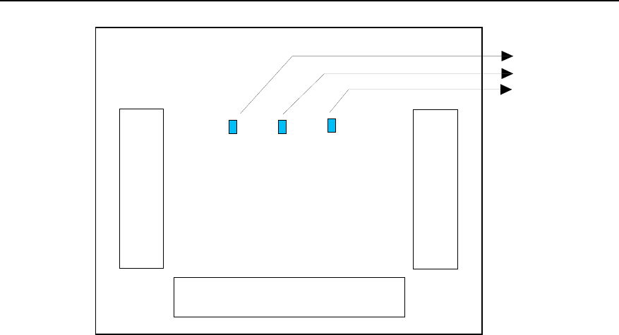
Technical Manual
Airbridge BTS3612A CDMA Base Station System Principle
Chapter 3 Radio Frequency Subsystem
3-21
Fan cover port (connect to BBFM)
BHPA indicator
FAN indicator
BTRM indicator
LED1 LED2 LED3
Fan 2 interface
Fan 1 interface
Figure 3-11 Structure of BBFL module
The BBFL consists of the following parts:
z Fan 1 interface module
It is a 4pin ordinary socket connector connected with the Fan 1, including power supply
input port and fan alarm output port.
z Fan 2 interface module
It is a 4pin ordinary socket connector connected with the Fan 2, including power supply
input port and fan alarm output port.
z Fan cover port interface module
It is connected with the fan cover of the BBFM.
III. Panel indicators
LED1: BTRM operating signal
LED2: Fan operating signal
LED3: BHPA operating signal
IV. Indices
BBFL dimensions: 55.0mm%25.0mm (Length%Width).
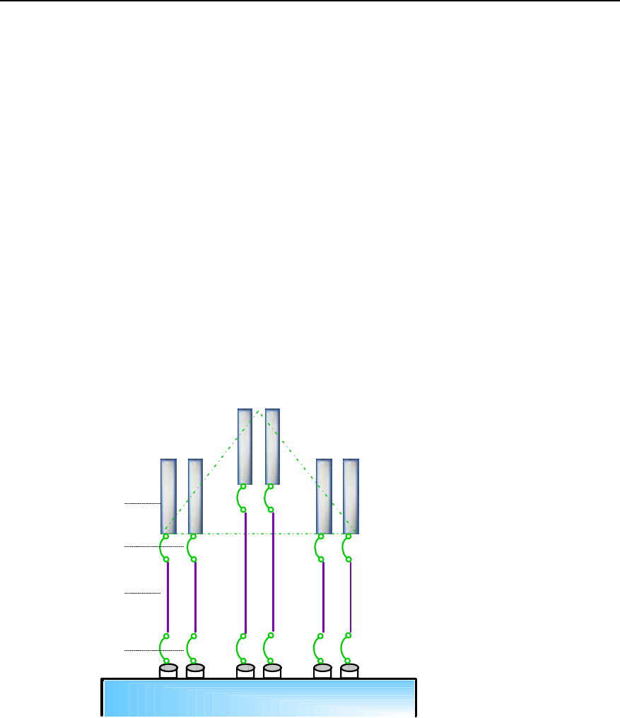
Technical Manual
Airbridge BTS3612A CDMA Base Station System Principle
Chapter 4 Antenna & Feeder Subsystem
4-1
Chapter 4 Antenna & Feeder Subsystem
4.1 Overview
The BTS antenna & feeder subsystem consists of two parts: the RF antenna & feeder,
and the satellite (GPS/GLONASS) synchronization antenna & feeder. The former
transmits the modulated RF signals and receives MS signals, while the latter provides
precise synchronization for the CDMA system.
4.2 RF Antenna & Feeder
The RF antenna & feeder of the BTS is composed of antenna, jumper from antenna to
feeder, feeder, and the jumper from feeder to cabinet-bottom, as shown in Figure 4-1.
Sector
α
Sector
β
Antenna
Feeder
Jumper
Jumper
BTS cabinet
Sector
γ
Figure 4-1 Structure of RF antenna & feeder
4.2.1 Antenna
Antenna is the end point of transmitting and start point of receiving. The type, gain,
coverage pattern and front-to-rear ratio of the antenna all will affect the system
performance. The network designer should select antenna properly based on the
subscriber number and system coverage.

Technical Manual
Airbridge BTS3612A CDMA Base Station System Principle
Chapter 4 Antenna & Feeder Subsystem
4-2
I. Antenna gain
Antenna gain is the capability of the antenna to radiate the input power in specific
directions. Normally, in the direction where the radiation intensity of the antenna is the
strongest, the higher the gain is, the stronger the field intensity will be in a faraway
place and the larger the effective coverage area will be. But there may be blind areas in
the vicinity.
II. Antenna pattern
Antenna pattern describes the radiation intensity of the antenna in all directions. The
horizontal antenna pattern is often used. It is also used as a standard to classify the
antennae
The BTS antenna is categorized in two types: omni antenna and directional antenna.
The directional antenna includes the following types: 120°, 90°, 65° and 33°.
III. Polarization
Polarization is used to describe the change path of the direction of the electric field. The
mobile communication system often uses uni-polarization antennas. Bi-polarization
antennae have been used recently. It is an antenna with two cross-over antenna
polarization directions. The isolation is above 30dB for both the +45o and -45o antennae.
The adoption of the bi-polarization antenna can save antennae, as one bi-polarization
antenna can replace two sets of independent uni-polarization antennae.
Normally bi-polarization directional antenna is used in directional cell. Compared with
the uni-polarization directional antenna, the bi-polarization directional antenna is
cost-effective, space saving and easy to install. However, uni-polarization omni
antenna is still adopted in omni cell.
IV. Diversity technology
Electrical wave propagation in urban area has the following features:
z Field intensity value changes slowly with places and time. It changes in the rule of
logarithmic normal distribution, which is called the slow attenuation.
z Field intensity transient value attenuates selectively due to the multi-path
transmission. The attenuation rules falls into Rayleigh distribution, which is called
the fast attenuation.
The fast attenuation, slow attenuation, multi-path effect, and shadow effect will impair
the quality of communication or even interrupts the conversation. Diversity technology
is one of the most effective technologies to tackle the attenuation problem. Diversity
receiving and combining technology can be used to minimize the attenuation when
there is little correlation between the two attenuated signals.

Technical Manual
Airbridge BTS3612A CDMA Base Station System Principle
Chapter 4 Antenna & Feeder Subsystem
4-3
There are polarized diversity and space diversity. In the present mobile communication
system, horizontal space diversity and polarized diversity are both supported. Space
diversity is effective when the distance between two antennae is over 10 wavelengths.
Polarized diversity facilitates antenna installation and saves space, therefore it is used
more and more extensively.
V. Antenna isolation
The receiving/transmitting antenna must be installed with sufficient isolation to
minimize the effect on the receiver. The isolation space is subject to the spuriousness
of the transmitter and the characteristics of the receiver.
4.2.2 Feeder
Normally, the standard 7/8 inch or 5/4 inch feeders are used to connect the antenna
and cabinet. In the site installation, 7/16 DIN connectors should be prepared based on
the actual length of feeders.
Three grounding cable clips for lightning protection should be applied at the tower top
(or building roof), feeder middle, and the end close to the cabinet-bottom. If the feeder
is excessively long, additional cable clips should be applied evenly in the middle.
Since 7/8 inch and 5/4 inch feeders should not be bent, the tower top (or building roof)
antenna and the feeder, cabinet and the feeder should be connected via jumpers. The
jumpers provided by Huawei are 1/2 inch, 3.5m long, and with 7/16DIN connectors.
The attenuation of the feeder often used is listed in Table 4-1.
Table 4-1 Attenuation (dB/100m) of the feeder (ambient temperature 20°C)
Frequency Band 7/8 inch feeder 5/4 inch feeder
450MHz 2.65dB 1.87dB
800MHz 3.9dB 2.8dB
1900MHz 5.9dB 4.51dB
Standard conditions: VSWR 1.0, ambient temperature 20°C (68°F).
4.2.3 Lightning Arrester (Optional)
When the BTS3612A works at the 1900MHz band, the lightning arrester is necessary,
but for other bands, it is not necessary.
The lightning arrester is used to prevent damage of lightning current to the antenna &
feeder system.

Technical Manual
Airbridge BTS3612A CDMA Base Station System Principle
Chapter 4 Antenna & Feeder Subsystem
4-4
Usually, there are two types of lightning arresters. The first type uses the microwave
principle to conduct the low frequency lightning current to the ground so as to sink the
current. The second one is a discharging tube, when the voltages at both ends of the
discharging tube reach a certain value, the tube conducts to sink the large current.
The second technique is used in BTS3612A. Lightning arrester should be installed
close to the BTS cabinet.
4.2.4 Tower-top Amplifier (Optional)
When the BTS3612A works at 1900MHz band, the tower-top amplifier (TA) is optional,
for the other bands, it is not necessary.
The TA is a low-noise amplification module installed on the tower. It is to amplify the
reverse signal from MS before the transmission loss occurs along the feeder. This
helps improve the receiving sensibility of the BTS system and the reverse coverage of
the system while lowering the transmitting power of MS and improving the conversation
quality.
Usually the triplex TA is configured. It is installed close to the antenna. This type of TA
consists of triplex filter, low-noise amplifier and feeder. The triplex filter is actually the
combination of two duplex filters. The signal from the antenna is first filtered off the
external interference at the triplex filter, and then is amplified by the low-noise amplifier,
and finally sent to the feeder.
Features of the TA include:
z The noise factor of TA is very low.
z The TA has a wide dynamic range, which is full adaptable to the change of
strength of signal received by antenna caused by different distances between the
MS and the BTS.
z The TA has the alarm bypass function.
z The TA is fed with feeder, so it has the feeding detection device.
z The TA adopts strict water-proof sealing and is adaptable to a wide range of
working temperatures (-40ÿC~70ÿC).
z The TA can sustain strong lightning strikes.
4.3 Satellite Synchronization Antenna & Feeder
4.3.1 Overview
Many important features of the CDMA system are closely related to and much
dependent on the global satellite navigation system. If the global satellite navigation
system stops working for a long time, the whole CDMA network will collapse.
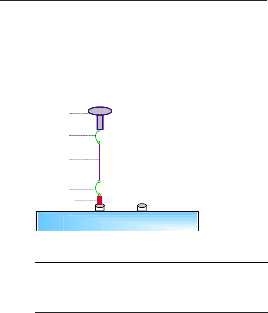
Technical Manual
Airbridge BTS3612A CDMA Base Station System Principle
Chapter 4 Antenna & Feeder Subsystem
4-5
In consideration of system security and reliability, the BTS receives signals of the GPS
system or of the GLONASS system through a satellite synchronization antenna &
feeder, to implement radio synchronization. In this way, the whole network can still
operate normally without any adverse effect when the GPS or GLONASS system is not
available.
A satellite synchronization antenna & feeder system is composed of an antenna, the
jumper from antenna to feeder, feeders, a lightning arrester and the jumper from feeder
to cabinet-bottom (the feeders and jumpers can be configured as needed). Figure 4-2
shows the structure.
BTS cabinet
Antenna
Feeder
Jumper
Jumper
Lightning arrester
Figure 4-2 Structure of satellite synchronization antenna & feeder
Note:
When the length of the feeder is within 100m, use the 1/2” feeder, which can be directly connected to the
antenna and lightning arrester without any jumper.
When the length of the feeder exceeds 100m, use the 7/8” feeder. In this case, a jumper is needed.
Generally, one BTS is configured with one set of satellite synchronization antenna &
feeder. However, if two BCKM boards are configured to further enhance the reliability of
the system, the two BCKMs each should be configured with one set of independent
satellite synchronization antenna & feeder. In Figure 4-2, two satellite synchronization
antenna & feeder interfaces are provided.
The following describes the application of the GPS and the GLONASS in a CDMA BTS.

Technical Manual
Airbridge BTS3612A CDMA Base Station System Principle
Chapter 4 Antenna & Feeder Subsystem
4-6
I. GPS
The GPS is a high precision all-weather satellite navigation system based on radio
communications. It can provide high precision information about 3D-position, speed
and time. The 3D-position is accurate to less than 10 yards (approx. 9.1m) in space; the
time is accurate to less than 100ns in time.
The GPS signals can be received and used as the reference frequency.
The whole system consists of three parts: space part, land control part and user part.
The space part is a group of satellites (altogether 24) 20,183 kilometers high, orbiting
the earth at a speed of 12 hours/circle.
The land control part consists of a main control center and some widely distributed
stations.
The user part includes GPS receivers and their supporting equipment.
II. GLONASS
The GLONASS is a global satellite navigation system developed by the former Soviet
Union and inherited by Russia. With 24 satellites distributed on 3 orbits, it has a
structure similar to the GPS, but a smaller coverage.
III. Application of GPS and GLONASS in CDMA BTS
The BTS3612A supports GPS/GLONASS satellite system synchronization mode,
providing two synchronization solutions (GPS or GPS/GLONASS) as required by the
user.
In the CDMA2000 1X system, the BTS is a user of the GPS or GLONASS, utilizing their
timing function. BTS3612A adopts smart software phase-lock and holdover
technologies to minimize interference such as signal wander and jitter caused by
ionosphere and troposphere errors of GPS or GLONASS satellites.
The timing signal of the GPS or GLONASS features high reliability and long-term
frequency stability. BTS3612A is equipped with a crystal clock that promises high
stability. The short-term stability of this crystal clock and the long-term stability of the
GPS or GLONASS combine to ensure the reliability and stability of the CDMA2000 1X
system clock.

Technical Manual
Airbridge BTS3612A CDMA Base Station System Principle
Chapter 4 Antenna & Feeder Subsystem
4-7
4.3.2 Antenna
I. GPS antenna
The GPS antenna is an active antenna. L1 band (1565~1585MHz) GPS signals
received by the antenna are filtered by a narrow-band filter and amplified by a
preamplifier. Then they are sent to a GPS receiver integrated in the BCKM.
II. GPS/GLONASS dual-satellite antenna
The GPS/GLONASS dual-satellite antenna is also an active antenna. It receives both
L1 GPS and GLONASS signals (1602~1611MHz).
4.3.3 Feeder
Normally, standard 1/2 inch or 7/8 inch feeders are used to connect the antenna and
the cabinet. In site installation, 7/16DIN connectors should be prepared based on the
actual length of feeders.
Three grounding cable clips for lightning protection should be applied at the tower top
(or building roof), feeder middle, and the end close to the cabinet-bottom. If the feeder
is excessively long, additional cable clips are needed.
Since the 7/8 inch feeder should not be bent, the tower top (or building roof) antenna
and the feeder, the cabinet and the feeder should be connected via jumpers. The
jumpers provided by Huawei are 1/2 inch, 3.5m long, with 7/16DIN connectors.
The feeder is mainly used to transmit GPS/GLONASS signals received by the
GPS/GLONASS antenna to the GPS/GLONASS receiver. It also provides power for the
antenna module to make pre-amplification.
4.3.4 Lightning Arrester
Like the lightning arrester of RF antenna & feeder, the satellite uses the lightning
arrester of antenna & feeder to protect the equipment from direct lightning stroke or
inductive lightning. One feeder is configured with one lightning arrester.
4.3.5 Receiver
I. GPS receiver
There are many types of GPS receivers. The following introduces the one with 8
parallel paths.

Technical Manual
Airbridge BTS3612A CDMA Base Station System Principle
Chapter 4 Antenna & Feeder Subsystem
4-8
This kind of GPS receiver is capable of tracking 8 satellites concurrently. It receives
GPS signals of band L1 and tracks C/A codes.
Inside the receiver, the RF signal processor makes frequency down-conversion to the
GPS signals received by the antenna to get the Intermediate Frequency (IF) signals.
The IF signals are then converted to digital signals and sent to 8-path code and carrier
correlator, where signal detection, code correlation, carrier tracking and filtering are
performed.
The processed signal is synchronized and sent to the positioning Micro Processing Unit
(MPU), which controls the operational mode and decoding of the GPS receiver,
processes satellite data, measures pseudo-distance and pseudo-distance increment
so as to figure out the position, speed and time.
The receiver should be powered with regulated 5V DC and the sensitivity of the
receiver is -137dBm.
II. Dual-satellite receiver
The principle of the dual-satellite receiver is similar to the GPS receiver. It has 20
receiving paths and can be upgraded from GPS L1 to GPS/GLONASS L1+L2 or other
solutions.
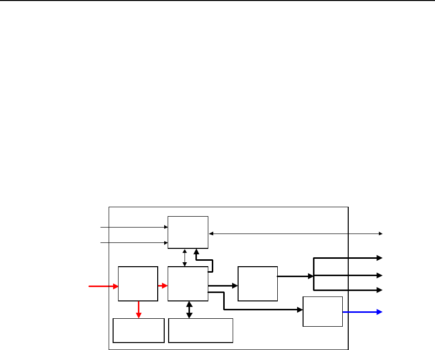
Technical Manual
Airbridge BTS3612A CDMA Base Station System Principle
Chapter 5 Power & Environment Monitoring Subsystem
5-1
Chapter 5 Power & Environment Monitoring
Subsystem
5.1 Overview
The functional structure of the power & environment monitoring subsystem is shown in
Figure 5-1.
PMU
AC
distribution
unit
Environment
monitor and
sensors
Battery subrack/
cabinet
+24VDC
RS485
RS485
DC
distribution
unit
-48VDC
220V AC
or
110V AC
Boolean v alue
Analog v alue BCKM
Baseband
boards and RF
modules
PSUAC/DC
PSUDC/
DC
Transmissio
n equipment
Heat
exchanger fan
Lamp
-48VDC
Air conditioner/
heat exchanger
Figure 5-1 Functional structure of the power & environment monitoring subsystem
The subsystem provides functions of power distribution and environment monitoring
(including temperature control).
The power distribution part includes the AC distribution unit, PSUAD/DC, the DC
distribution unit, PSUDC/DC, PMU, and the battery subrack or cabinet.
The environment monitoring part includes the PMU and the air conditioner or heat
exchanger.
The following sections describe the working principles of power distribution and
environment monitoring. As the PMU mainly implements the monitoring functions, it will
be introduced in Section 5.3, "Environment Monitoring"
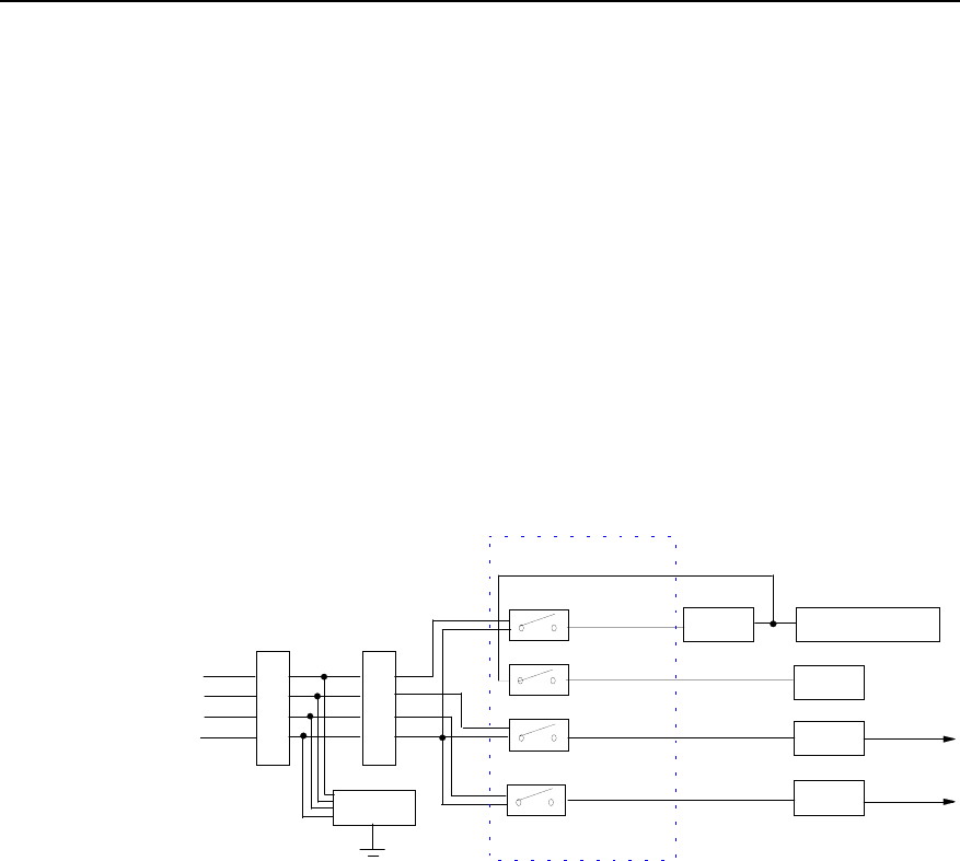
Technical Manual
Airbridge BTS3612A CDMA Base Station System Principle
Chapter 5 Power & Environment Monitoring Subsystem
5-2
5.2 Power Distribution
5.2.1 AC Distribution
The BTS3612A supports four types of AC power supplies: three-phase 220V AC,
single-phase 220V AC, three-phase 110V AC and single-phase 110V AC.
I. Distribution of three-phase 220V AC
The three-phase 220V AC passes through the lightning protector and the
ElectroMagnetic Interference (EMI) filter before reaching the AC distribution unit. From
the AC distribution unit, the power is distributed to the voltage regulator, PCUAC/DC and
power sockets (reserved). Each distribution path is protected with an air switch at the
input end. Detailed distribution paths are shown in Figure 5-2.
Lightning
arrester
220VAC
Air switch
A
N
B
N
C
N
63A
63A
Voltage
regulator Air conditioner/heat
exchanger
32A
PSUAC/DC
Reserved
10A
AC distribution unit
A,N
B,N +24V DC
N
A
C,N +24V DC
PSU
EMI filter
AC/DC
C
B
Figure 5-2 Distribution of three-phase 220V AC
The air switch, lightning protector and EMI filter are all installed in the power lightning
protector/filter box.
II. Distribution of single-phase 220V AC
If the single-phase 220V AC is used for the BTS3612A, a wiring terminal for phase
conversion should be equipped before the air switch to convert the single-phase power
into three-phase power. The power distribution in the cabinet is the same as that of the
three-phase 200V AC, as illustrated in Figure 5-3.
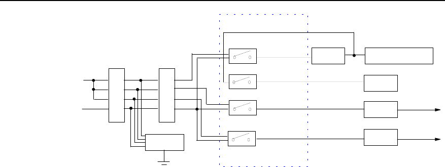
Technical Manual
Airbridge BTS3612A CDMA Base Station System Principle
Chapter 5 Power & Environment Monitoring Subsystem
5-3
Lightning
arrester
220VAC
Air switch
A
N
B
N
C
N
63A
63A
Voltage
regulator Air conditioner/heat
exchanger
32A
PSUAC/DC
Reserved
10A
AC distribution unit
A,N
B,N +24V DC
N
L
C,N +24V DC
PSU
EMI filter
AC/DC
Figure 5-3 Distribution of single-phase 220V AC
III. Distribution of three-phase 110V AC
If the single-phase 110V AC is used for the BTS3612A, an air conditioner (or heat
exchanger) and a PCUAC/DC that support 110V AC should be configured. The rest
configuration is the same with the distribution of three-phase 220V AC.
IV. Distribution of single-phase 110V AC
If the single-phase 110V AC is used for the BTS3612A, a wiring terminal for phase
conversion should be equipped before the air switch to convert the single-phase power
into three-phase power. The rest configuration is the same with the distribution of
three-phase 110V AC.
5.2.2 DC Distribution
I. Distribution of –48V DC
Figure 5-4 illustrates how the 220V AC is converted into –48V DC and then distributed.
The 220V AC is output by the AC distribution unit to the 220V AC power input busbar
on the backplane of the PSUAC/DC subrack. The PSUAC/DC converts the power and outputs
multiple –48V DC supplies to the busbar.
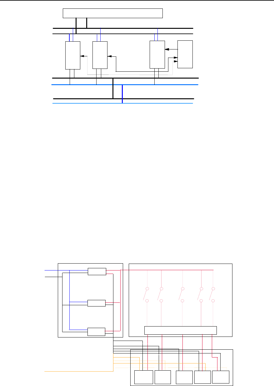
Technical Manual
Airbridge BTS3612A CDMA Base Station System Principle
Chapter 5 Power & Environment Monitoring Subsystem
5-4
PSU PSU PSU
220V AC
Input busbar
Output busbar
-48V DC
DC distribution busbar
PMU
.....
AC distribution unit
Figure 5-4 AC-DC conversion and distribution of –48V DC
Then the DC distribution busbar sends the –48V DC to the power consumption units
such as the PSUDC/DC subrack, batteries, transmission equipment, fans, lighting
equipment, and the internal and external circulation fans in the heat exchanger.
II. Distribution of +24V DC
Figure 5-5 illustrates how the –48V DC is converted into +24V DC and then distributed.
The -48V DC is output to the -48V DC power input busbar on the backplane of the
PSUDC/DC subrack. The PSUDC/DC converts the power and outputs multiple +24V DC
supplies to the output busbar. Then the power is sent to the distribution busbar of the
DC distribution box on the top of the cabinet along the cables in the cabling trough.
Wiring terminals
-48VIN
GND
DC/DC
DC/DC
DC/DC
PSUDC/DC subrack
Switch box
DU
BTRM0
PGND
RLDU1
BTRM5
9 service processing units RLDU0
...
...
Figure 5-5 DC-DC conversion and distribution of +24V DC

Technical Manual
Airbridge BTS3612A CDMA Base Station System Principle
Chapter 5 Power & Environment Monitoring Subsystem
5-5
To ensure the normal power supply to other power consumption units when the power
to one of the unit is disconnected due to over current, a separate over-current
protection unit is equipped in the distribution box for each power consumption unit.
Through these protection units, the busbar distributes the power to the terminals on the
back panel, which will supply the power to various consumption units.
5.2.3 Power Distribution Devices
I. PSUAC/DC
The PSUAC/DC is composed of an AC-DC converter and a power monitor. The former
converts the ~220V AC (local mains) into –48V DC; the later detects status of the
PSUAC/DC and reports alarms.
II. PSUDC/DC
The PSUDC/DC is composed of a Direct Current - Direct Current (DC-DC) converter and
a power monitor. The former converts the –48V DC into +24V DC; the later detects
status of the PSUDC/DC and reports alarms.
III. Batteries
Note:
Batteries are optional.
When the local mains supply fails, batteries can maintain the normal operation of the
BTS for a period of time. A built-in battery subrack and an auxiliary battery cabinet are
available to satisfy different requirements.
z Built-in battery subrack
The built-in battery subrack is configured in the auxiliary cabinet. It can be installed with
four 12V/65Ah storage batteries to maintain the normal operation of the BTS2612A in
S(1/1/1) configuration for more than 30 minutes.
z Auxiliary battery cabinet
The auxiliary battery cabinet can hold up to twenty-four 2V/650Ah or 2V/300Ah or
2V/200Ah batteries to power the system for a longer period after the mains failure. An
auxiliary battery cabinet fully configured with twenty-four 2V/650Ah batteries can
support the normal operation of BTS3612A in S(1/1/1) configuration for more than eight
hours.
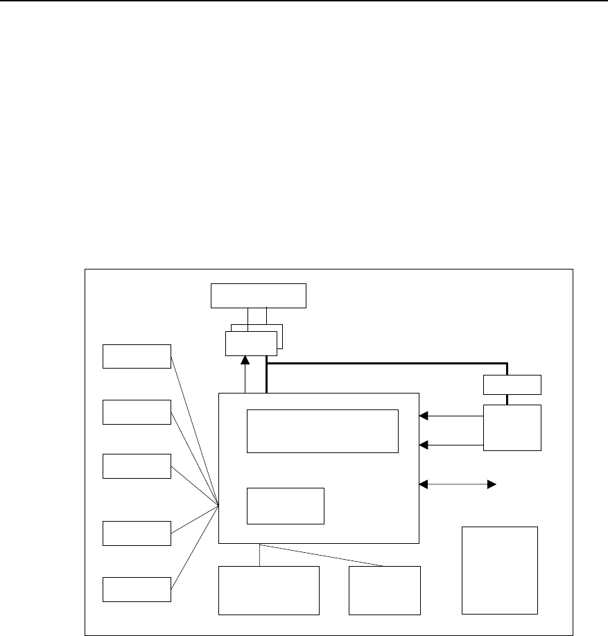
Technical Manual
Airbridge BTS3612A CDMA Base Station System Principle
Chapter 5 Power & Environment Monitoring Subsystem
5-6
5.3 Environment Monitoring
5.3.1 Structure of Monitoring System
As an outdoor BTS, the BTS3612A provides comprehensive power & environment
monitoring functions, which are implemented through sensors, TCU and PMU. The
temperature inside the cabinet is controlled by an independent temperature control
device.
The monitoring system is shown in Figure 5-6.
Smoke
sensor
Door status
sensor
Temp
sensor
Water
sensor
Power control & battery
management
Environment
monitoring PMU
7 reserved
boolean value
Air switch
fuse
detector
PSU
220/110VAC
PSU
Current
measurement
Temp
measurement
Protector
Battery
To BCKM of
baseband
subsystem
-48V Busbar
RS485
TCU
Temperature
control
Figure 5-6 Monitoring system of BTS3612A
I. Monitoring functions of PMU
The PMU monitors on a real-time basis control value signals, Boolean value signals,
current/voltage analog signals and environment value analog signals.
Control value signals include:
z Equal floating charge and current-limiting control of batteries
z Protective load connect/disconnect of batteries
Boolean value signals include:
z Air conditioner / heat exchanger failure alarm.

Technical Manual
Airbridge BTS3612A CDMA Base Station System Principle
Chapter 5 Power & Environment Monitoring Subsystem
5-7
z AC lightening arrester alarm.
z Battery interface lightening arrester of battery cabinet.
z Cabinet smoke alarms, water alarms, and door control alarms.
Current/voltage analog signals include:
z Current of the battery group (A)
z Total load current (A)
z Busbar AC voltage (V)
Environment value analog signals include:
z Temperature (oC) inside the cabinet (with sensors)
z Humidity (RH%) inside the cabinet (with sensors)
Power system management:
z PSU failure and PSU protection alarm.
z The communications (between the PSU and the PMU) failure alarm.
z Mains available or unavailable alarm.
z Mains over voltage or under voltage alarm.
z DC over voltage or under voltage alarm.
z Fuse status value of the batteries (-0.3VDC<Normal voltage difference<0.3VDC).
II. Temperature control
The BTS3612A is an outdoor BTS with a sealed structure. When it operates in a
high-temperature environment, the heat generated by the devices may quickly raise
the temperature inside the cabinet.
To keep the temperature inside within a normal range in the extreme (either high or low)
temperature environment, an air conditioner or heat exchanger can be installed in the
cabinet. The equipped air conditioner or the heat exchanger itself is highly reliable and
able to report alarms when faults occur.
5.3.2 Monitoring Devices
I. Sensors
Sensors are installed inside the BTS3612A cabinet and the auxiliary battery cabinet.
The BTS3612A cabinet is equipped with temperature sensor, door status sensor, water
sensor and smoke sensor, while the auxiliary battery cabinet is only equipped with
temperature sensor and door status sensor.
II. TCU
The TCU supervises the temperature of the main equipment. When the temperature is
too high or too low, the TCU will cut off the 220V AC input and the –48V DC output from
the batteries, and shut down some boards to protect the main equipment.

Technical Manual
Airbridge BTS3612A CDMA Base Station System Principle
Chapter 5 Power & Environment Monitoring Subsystem
5-8
III. PMU
The PMU is the core of the monitoring system. It is responsible for collecting,
processing and reporting all the environment variables.
IV. Air conditioner
The air conditioner can realize closed-loop control over the temperature inside the
cabinet.
When the air conditioner finds that the temperature is too low, it will start its heating
plates and internal fans to heat the BTS. When the temperature is too high, the air
conditioner will activate the cooling function to lower the temperature to a normal
degree.
V. Heat exchanger
A heat exchanger can also be used instead of the air conditioner to control the
temperature inside the cabinet. The heat exchanger has high/low-temperature alarm
circuits. When the temperature inside the cabinet is higher than the temperature
outside, it will discharge the heat through closed circulation. Compared with the air
conditioner, the heat exchanger has a simpler structure with fewer components, and
thus is more cost-effective.

Technical Manual
Airbridge BTS3612A CDMA Base Station
System Principle
Chapter 6 Lightning Protection and Grounding
6-1
Chapter 6 Lightning Protection and Grounding
6.1 Overview
I. Lightning Protection
Lightning protection system for communication equipment includes external lightning
protection system and internal lightning protection system.
The external lightning protection system is to protect the equipment against direct
lightning stroke, including lightning receivers, lightning down-leading cables and
grounding devices.
The internal lightning protection system is to protect the equipment against indirect
stroke, such as thunder bolt induction, reverse lightning stroke, lightning wave intrusion
and other lightning strokes that might endanger human beings and the equipment.
II. Equipment Grounding
The purpose of equipment grounding is to provide the equipment with the capability of
protecting against external electromagnetism interference and to ensure the safety of
human beings and the equipment. The key of lightning protection is grounding,
because a fine grounding can provide the equipment with a low-resistance lightning
electricity discharging channel.
6.2 BTS Lightning Protection Principle
6.2.1 Principle and Characteristics
As an outdoor BTS, the BTS3612A adopts multiple internal and external lightning
protection measures.
I. Measures of external lightning protection
The BTS3612A adopts the equalized electric potential combining/grounding
technology specified by the IEC and the ITU-T. This design ensures that no grounding
electric potential difference is generated during lightning striking and thus no damage is
caused to the equipment.

Technical Manual
Airbridge BTS3612A CDMA Base Station
System Principle
Chapter 6 Lightning Protection and Grounding
6-2
II. Measures of internal lightning protection
The AC lightning arrester at the AC input port prevents the AC from direct lightning
stroke or inductive lightning. The lightning protection index of the AC input port is 40kA.
E1 lightning protection board at the E1 port of the BTS3612A protects E1 signal ports.
The lightning protection index of E1 port is 5kA.
The antenna and feeder lightning arrester at the feeder inlet protects the BTS against
the striking current coupled into the feeder when the steel tower gets lightning stoke.
The equalized electric potential connection and insulation design of the cabinet prevent
the cabinet from the damage of lightning stroke.
6.2.2 Lightning Protection for AC Power
The overall power supply for the BTS3612A is large, so an AC lightning arrester is used
at the AC input port as the first level of lighting protection measures. This parallel
lightning protection can effectively prevent the BTS3612A from the damage of lightning
stroke. This protection function:
z Adopts symmetric compound circuits, applicable to the power supply environment
with poor electric network quality.
z Adopts temperature-controlled circuit breaking technology with embedded
over-current protection circuits to prevent the cabinet from the danger of fire.
z Adopts full protection of both common mode and differential mode.
z Adopts dual-color luminotrons to indicate the working states of the cabinet.
6.2.3 Lightning Protection for Trunk Cables
The BTS3612A supports multiple transmission modes: E1 (75Ωcoaxial cables and
120Ω twisted pairs), T1 (100Ω twisted pairs), SDH and microwave transmission.
E1/T1 ports are liable for lightning induction. Therefore, various lightning protection
measures for E1/T1 ports are introduced in the following.
The BESP is added at the trunk cable inlet for the lightning protection at E1/T1 ports of
the BTS3612A. The connection is shown in Figure 6-1.
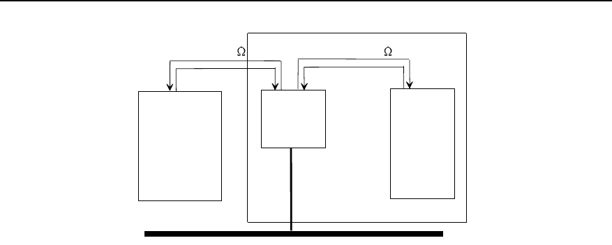
Technical Manual
Airbridge BTS3612A CDMA Base Station
System Principle
Chapter 6 Lightning Protection and Grounding
6-3
BESP
BTS
Transmission
equipment
BCIM
75/120/100
Grounding bar
75/120/100
Figure 6-1 Connection to BTS via trunk cables
All E1 cables achieve the lightning protection through the E1 lightning protection board.
The circuits on the board can prevent the lightning current going into the cabinet
through E1/T1 cables when the trunk lines get lightning stroke, and the circuits can also
discharge most of the current through the electricity discharge tube when large current
strikes the cabinet.
6.2.4 Lighting Protection for Antenna & Feeder Subsystem
The Radio Frequency (RF) equipment of the BTS shall be placed within the protection
range of the lightning rod, which is the precondition to ensure the normal performance
of BTS lightning protection system.
I. Lightning protection for RF antenna & feeder
The lightning protection function for the antenna & feeder protects the equipment
against secondary lightning attack, i.e. the inductive lightning. Inductive lightning
means that the feeder receives inductive current upon a lightning attack, which may
cause damage to the equipment.
Inductive lightning can be prevented effectively in three ways:
z The feeder is grounded at least at three points. In actual implementation, the
number of grounding points depends on the length of the feeder.
z For 450MHz band and 800MHz band, the RF antenna & feeder part and CDU (or
DDU, DFU) are grounded through an internal path. The lightning current induced
by the antenna & feeder can be directly discharged to the ground through the
grounding point. In addition, the CDU (or DDU, DFU) itself features strong
protection capability against lightning current, and can satisfy the normal
protection requirements without extra lightning protectors.

Technical Manual
Airbridge BTS3612A CDMA Base Station
System Principle
Chapter 6 Lightning Protection and Grounding
6-4
z For 1900MHz band, when the TMA is configured, the DDU with BIAS T should be
configured, the BTS provides the TMA with power supply through the DDU, so
lightning arrester is needed at the feeder port of the BTS; If the TMA is not
configured, the lightning arresters is also not needed.
II. Lighting protection for satellite synchronization antenna & feeder
The GPS/GLONASS satellite synchronization antenna & feeder is under the protection
of lightning rods. Other lightning protection measures include:
z Grounding of feeder at three points: In actual implementation, the number of
grounding points depends on the length of the feeder.
z External lightning protector: In normal condition, a lightning arrester is connected
to the BTS side to avoid the possible damage to the BTS equipment caused by the
lightning current induced by feeder cores.
6.3 Grounding of BTS Equipment
6.3.1 Internal Grounding of Cabinet
Grounding terminals are installed at the cable outlet port, the bottom and the door of the
cabinet.
Busbars are installed in the main cabinet, with common grounding cables. Various
equipment connects to the grounding system of the cabinet using the grounding
cables.
Various metal components of the BTS3612A are of high electric conductivity and no
insulation paint is applied to the connection points of metal components.
Cabinet frames, power distribution unit, PSU and air-conditioner regulator are all
equipped with metal shells, which are reliably connected to the metal mechanical parts
in the cabinet.
6.3.2 External Grounding of Cabinet
A protection grounding (PGND) cable is connected from the PGND of BTS3612A to the
nearest grounding copper bar of the office.
6.3.3 Grounding of AC Lightning Arrester
Grounding device is installed in the vicinity of AC lighting arrester and connects the
grounding cables of AC lightning arrester to the GND of the grounding device. The
dual-color (yellow and green) plastic insulation copper-core conducting cables are
adopted with the cross-sectional area less than 6mm2 and cable length less than 10cm.

Technical Manual
Airbridge BTS3612A CDMA Base Station
System Principle
Chapter 6 Lightning Protection and Grounding
6-5
The grounding device of the AC lightning arrester is well connected to the mechanical
parts of the cabinet, and the contact resistance is less than 50mΩ.
6.3.4 Grounding of Transmission Equipment
Grounding bar is installed in the vicinity of the transmission equipment. The GND
cables from the transmission equipment are directly connected to the grounding bar.
The dual-color (yellow and green) plastic insulation copper-core conducting cables with
the cross-sectional area less than 6mm2 and cable length less than 20cm are used for
the grounding cables.
The grounding bar of the transmission equipment is well connected to the mechanical
parts of the cabinet, and the contact resistance is less than 50mΩ.
6.3.5 Grounding of Overhead E1/T1 and HDSL Cables
Metal sheath grounding clamp for dedicated E1/T1 and HDSL overhead cables shall be
used for transmission lightning protection equipment.
Necessary grounding measures shall be taken before the metal sheaths of E1/T1 and
HDSL overhead cables are led into the Roxtec module.
6.3.6 Grounding of BTS Surge Protector
The grounding cables for the antenna & feeder lightning arrester are connected to the
nearest grounding bar, which is connected to the grounding system of the cabinet.
The grounding cables for E1 lightning arrester and HDSL lightning arrester are
grounded via the mechanical parts of the cabinet, and the length is less than 20cm.

Technical Manual
Airbridge BTS3612A CDMA Base Station System Principle
Chapter 7 BTS Signal Flows
7-1
Chapter 7 BTS Signal Flows
7.1 Overview
BTS signals include Abis traffic signal, Abis signaling message, O&M signal, clock
signal, and local Man-Machine Interface (MMI) signal. These signals form various flows
in the transmission from the Abis interface to the Um interface, as shown in Figure 7-1
(The flows are identified by different colors).
I. Abis signal
The Abis traffic signal, Abis signaling message and O&M signal are adapted and
carried through Asynchronous Transfer Mode (ATM) protocols. At different interfaces,
different physical links are used as ATM links.
z At the Abis interface, the physical links are E1/T1 links.
z Between the baseband processing boards, the physical link is cell bus.
z The physical links for the IQ data exchange between the BRDM and various
BCPMs are electrical Gbit Ethernet buses.
z The physical links for the IQ data exchange between the BRDM and various
BTRMs are optical Gbit Ethernet buses.
The baseband signals (including the Abis traffic signal, Abis signaling message and
O&M signal) are processed by the BTRM and converted into RF signals before the
transmission. In the reverse direction, the BTRM receives RF signals and converts
them into baseband signals.
II. Clock signal
As a synchronous system, the CDMA2000 1X requires precise clock reference for
synchronization. Figure 7-1 shows satellite synchronization signals are used as clock
reference.
III. Local MMI signal
The BTS provides an interface for local maintenance, through which users can perform
operations and maintenance using MMI commands. The local MMI signal is essentially
a kind of O&M signal from the local maintenance terminal (compared with the signal
coming from a remote terminal through the BSC), so it will not be introduced separately.
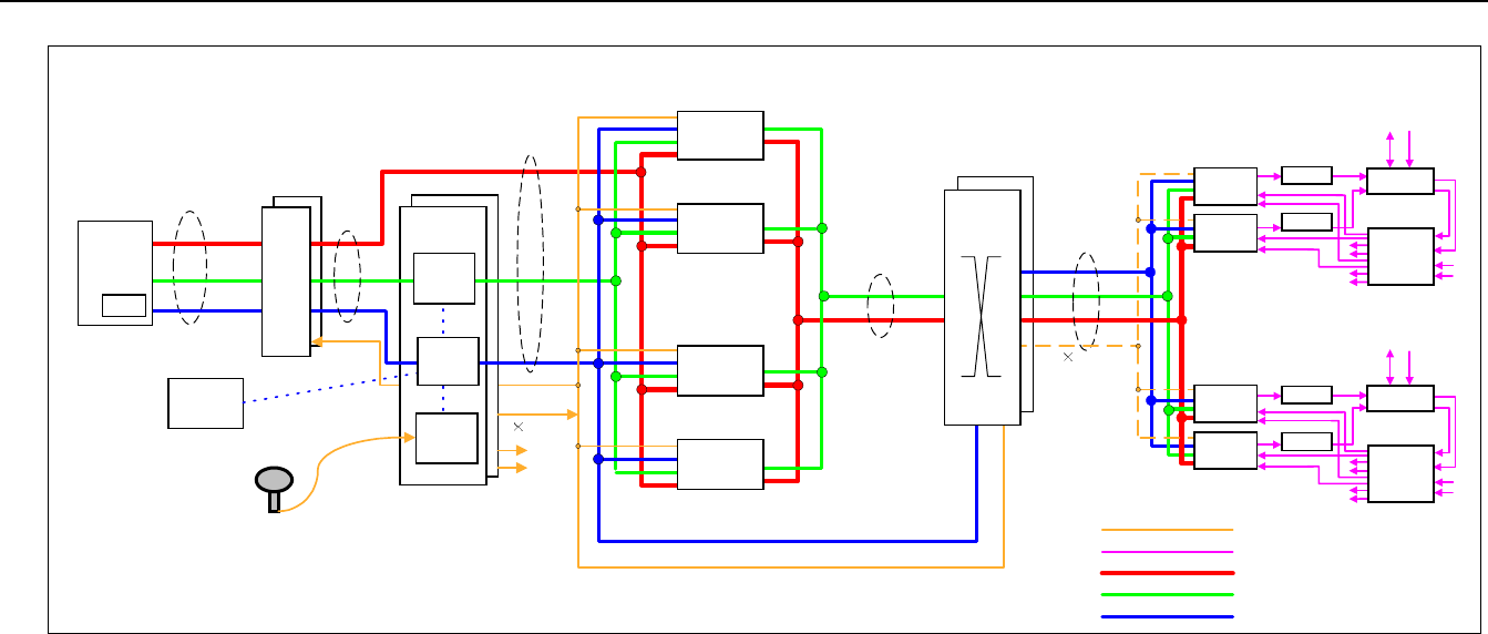
Technical Manual
Airbridge BTS3612A CDMA Base Station System Principle
Chapter 7 BTS Signal Flows
7-2
MMI
BCKM
CellBus
CLK
MC
OMU
...
CellBus
Gbit Ethernet
(Electric Interface) RLDU
BHPA DDU
RLDU
BHPA
RLDU
BHPA DDU
RLDU
BHPA
...
...
...
Gbit Ethernet
(Optical Interface)
Antenna & Feeder
Antenna & Feeder
Satellite Receiver
Antenna & Feeder
BCPM
BCPM
BCPM
1PPS, UTC 2S
10MHz
2S, 25MHz
BCIM
25MHz
100 1.228MHz
BTRM
BTRM
BTRM
BTRM
BRDM
BSC
BAM
E1/T1
Abis signaling
OAM
Abis traffic
16 1.228MHz
BCPM
Abis signaling signal
OAM Signal
Abis traffic signal
RF singal
Clock Signal
Figure 7-1 BTS signal flows

Technical Manual
Airbridge BTS3612A CDMA Base Station System Principle
Chapter 7 BTS Signal Flows
7-3
7.2 Abis Traffic Signal Flow
The Abis traffic is carried by the Fundamental Channel (FCH), the Supplemental
Channel (SCH) and the Dedicated Control Channel (DCCH). The FCH and DCCH
carry voice traffic and inband signal, while the SCH carries data traffic.
The Abis traffic signal flow is represented by the red continuous line in Figure 7-1. The
following introduces the signals in the forward and the reverse directions respectively.
I. Forward
1) The ATM cells from the BSC are carried by E1/T1 links to the BCIM. The BCIM
processes the ATM cells through the IMA, and then under the control of BCKM
sends the signal to the BCPM through the Cell Bus.
2) The BCPM completes channel processing. The baseband signals carrying the
Abis traffic (received over the FCH, SCH and DCCH) from the BCIM are coded,
interleaved, spread, modulated and multiplexed by the BCPM before being sent to
the BRDM over the electrical Gbit Ethernet interface.
3) The BRDM allocates channel resources, and sends the baseband signals over the
optical Gbit Ethernet interface to the BTRM.
4) The BTRM performs demultiplexing, up-conversion and wave filtering on the
received baseband signals, and sends them to the BHPA.
5) The BHPA amplifies the signals and forwards them to the DDU, from where the
signals will be transmitted by the antenna.
II. Reverse
In the reverse direction the signals are handled in the reverse order.
1) Through the main and diversity antennae, the DDU receives two CDMA signals
transmitted from the MS. After being divided and amplified by the RLDU, the
signals are sent to the BTRM.
2) The BTRM performs wave filtering, down-conversion and multiplexing on the main
and diversity signals, and sends them to BRDM over the optical Gbit Ethernet.
3) The BRDM allocates channel resources, and sends the baseband signals over the
electrical Gbit Ethernet interface to the BCPM.
4) The BCPM completes channel processing. The baseband signals carrying the
Abis traffic (received over the FCH, SCH and DCCH) from the BRDM are
demultiplexed, demodulated, de-interleaved and decoded by the BCPM. Then
under the control of BCKM, the obtained signals are sent to the BCIM over the Cell
Bus in form of ATM cells.
5) The ATM cells are processed by the BCIM through the IMA, and then sent to the
BSC over the E1/T1 link.

Technical Manual
Airbridge BTS3612A CDMA Base Station System Principle
Chapter 7 BTS Signal Flows
7-4
7.3 Abis Signaling Message Flow
The Abis signaling messages are carried by the Access Channel (ACH) and the Paging
Channel (PCH). These messages are refer to as outband signals (compared to the
inband signals in the Abis traffic).
The Abis signaling message flow is represented by the green continuous line in Figure
7-1. The following introduces the flow in the forward and the reverse directions
respectively.
I. Forward
1) The ATM cells from the BSC are carried by the E1/T1 link to the BCIM. The BCIM
processes the ATM cells through IMA, and then under the control of the MC of the
BCKM sends the signal to BCPM through the Cell Bus.
2) The BCPM completes channel processing. The baseband signals carrying the
Abis signaling messages (received over the PCH) from the BCIM are coded,
interleaved, spread, modulated and multiplexed by the BCPM before being sent to
the BRDM over the electrical Gbit Ethernet interface.
3) The BRDM allocates channel resources, and sends the baseband signals over the
optical Gbit Ethernet interface to the BTRM.
4) The BTRM performs demultiplexing, up-conversion and wave filtering on the
received baseband signals, and sends them to the BHPA.
5) The BHPA amplifies the signals and forwards them to the DDU, from where the
signals are transmitted by the antenna.
II. Reverse
In the reverse direction the signals are handled in the reverse order.
1) Through the main and diversity antennae, the DDU receives two CDMA signals
transmitted from the MS. After being divided and amplified by the RLDU, the
signals are sent to the BTRM.
2) The BTRM performs wave filtering, down-conversion and multiplexing on the main
and diversity signals, and sends them to BRDM over the optical Gbit Ethernet.
3) The BRDM allocates channel resources, and sends the baseband signals over the
electrical Gbit Ethernet interface to the BCPM.
4) The BCPM completes channel processing. The baseband signals carrying the
Abis traffic (received over the ACH) from the BRDM are demultiplexed,
demodulated, de-interleaved and decoded by the BCPM. Then under the control
of BCKM, the obtained signals are sent to the BCIM over the Cell Bus in form of
ATM cell.
5) The ATM cells are processed by the BCIM through IMA, and then sent to the BSC
over the E1/T1 link.

Technical Manual
Airbridge BTS3612A CDMA Base Station System Principle
Chapter 7 BTS Signal Flows
7-5
7.4 O&M Signal Flow
The operations and maintenance over the BTS, originated either from the remote BAM
or from the local maintenance terminal, are implemented by the OMU on the BCKM.
The blue continuous lines in Figure 7-1 represent the O&M signal flows between the
OMU and various boards in the BTS, while the blue dotted lines represent the flows
between the OMU and the MC and CLK units on the BCKM.
7.5 Clock Signal Flow
The BCKM receives satellite signals through the GPS/GLONASS synchronization
antenna. The CLK unit processes the received signal and outputs 2S signal, 25MHz
signal and 16%1.228MHz signal to the clock bus. The boards in the BTS obtain the
required clock signals from the clock bus.
z The BCIM gets the 25MHz clock signal from the clock bus, which will be
processed by the clock unit of the BCIM to produce other desired clock signals.
z The BRDM gets the 2S signal, 25MHz signal and 16%1.228MHz signal from the
clock bus, which will be processed by the clock unit of the BRDM to produce other
desired clock signals.
z The BCPM gets the 2S signal, 25MHz signal and 16%1.228MHz signal from the
clock bus, which will be processed by the clock unit of the BCPM to produce other
desired clock signals.
z The BTRM gets 100%1.228MHz signal from the Gbit Ethernet bus (optical
interface), which will be processed by the clock unit of the BTRM to produce other
desired clock signals such as 48%1.228MHz, 50%1.228MHz and 2S signals.

Technical Manual
Airbridge BTS3612A CDMA Base Station System Principle
Chapter 8 BTS Configuration
8-1
Chapter 8 BTS Configuration
This chapter details the configuration of each part of BTS based on the brief
introduction to main cabinet, auxiliary cabinet, and cabinet door in Chapter 1.
8.1 Configuration Principle
BTS3612A applies outdoors It is highly integrated and is equipped with the excellent
protection function.
To configure BTS3612A, observe the following rules that are listed in the order of
precedence.
z Use the trunk cables as few as possible.
z Use the antennae as few as possible.
z Use the cabinets as few as possible.
The conformance to the above rules can facilitate the installation and expansion of
BTS.
8.2 Configuration of Main Equipment
8.2.1 Configuration of Baseband Boards
The baseband boards include BCIM, BCPM, BRDM and BCKM. The baseband
subrack in full configuration is shown in Figure 8-1. The slots are numbered uniformly.
However, the boards are numbered according to the board type.
Slot No.
Board No.
0
B
C
I
M
1
B
C
I
M
2
B
C
P
M
3
B
C
P
M
B
C
K
M
B
C
K
M
B
R
D
M
B
R
D
M
B
C
P
M
B
C
P
M
B
C
P
M
567891011
0145 0 10191011
4
B
C
P
M
8
Figure 8-1 Baseband subrack in full configuration

Technical Manual
Airbridge BTS3612A CDMA Base Station System Principle
Chapter 8 BTS Configuration
8-2
I. BCIM
BCIM has two versions: QC51BCIM and QC52BCIM. QC51BCIMsupports eight E1
links. Compared with QC51BCIM, QC52BCIM has more functions as follows: timeslot
cross-connection, fractional ATM transmission, and T1 transmission functions.
For the configuration of BCIM links, refer to the following typical data:
z For S(1/1/1) BTS, configure one E1/T1 link.
z For S(2/2/2) BTS, configure two E1/T1 links.
The above data is based on CDMA2000 1X system. For IS95 system, the above
quantity can be reduced by half.
When the transmission resource is limited, the fractional ATM network function of
QC52BCIM can be deployed to configure specific timeslot in a specific E1/T1 link to
the BTS.
II. BCPM
At most 6 BCPMs can be configured in the baseband subrack. There are two types of
BCPMs.
z The processing capability of type-A BCPM is 64 reverse channels and 128
forward channels.
z The processing capability of type-B BCPM is 128 reverse channels and 256
forward channels
BCPMs are configured based on the channel processing capability required by the
system, with consideration of BTRM quantity and board types. Typical configurations
are listed in Table 8-1.
The board Nos. of BCPMs are not successive. The left three are numbered as No.4,
No.5, and No.8, while the right three are numbered as No.9, No.10, and No.11.
Table 8-1 Configuration of BCPMs
BTS configuration Number of type-A BCPM Number of type-B BCPM
O(1) 1 Not recommended
O(2) 2 Not recommended
S(1/1/1) 2 1
S(2/2/2) 4 2
The above configurations are for CDMA2000 1X system. For 3-sector configuration,
type-B BCPMs are recommended. For IS95 configuration, the quantity should be
reduced by half.

Technical Manual
Airbridge BTS3612A CDMA Base Station System Principle
Chapter 8 BTS Configuration
8-3
Normally, redundancy is not required. If one board fails, the system will automatically
shield the faulty board. In this case, the system capacity decreases, but the service is
normal.
III. BRDM
There are two types of BRDM, namely multi-mode BRDM and single-mode BRDM.
The multi-mode BRDM is used to connect the BTRM in the cabinet, while the
single-mode BRDM is used to cascade the ODU3601C.
Providing 6 pairs of ports for leading out optical fibers, the multi-mode BRDM can be
connected with 6 BTRMs.
Providing 3 pairs of ports for leading out optical fibers, the single-mode BRDM can be
connected with three ODU3601Cs in star networking.
Table 8-2 Configuration of BRDM
Cabinet
configuration Connected with
ODU3601C Configuration of BRDM
Yes One multi-mode BRDM and one
single-mode BRDM
Single-cabinet
configuration No One multi-mode BRDM
Yes
One multi-mode BRDM and one
single-mode BRDM. The number of
carrier configured for a combined
cabinet does not exceed 6.
Combined-cabinet
configuration
No Two multi-mode BRDMs
IV. BCKM
Normally, one BCKM is enough. For reliability purpose, two BCKMs can be used
(active/standby mode).
The BCKM receives GPS/GLONASS signal as clock source. When two BCKMs are
configured, two sets of independent satellite synchronization antenna & feeder
systems are required.
8.2.2 Configuration of RF Modules
The radio modules include BTRM, BHPA, RLDU and CDU/DDU/DFU. The carrier
subrack and the duplexer subrack in full configuration is shown in Figure 8-2.
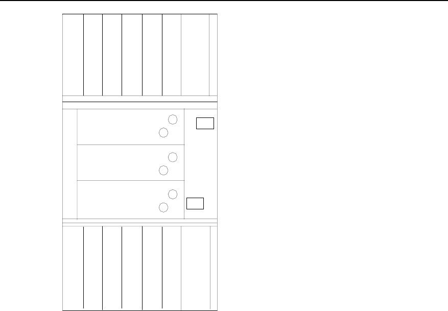
Technical Manual
Airbridge BTS3612A CDMA Base Station System Principle
Chapter 8 BTS Configuration
8-4
DFU/DDU/CDU2
DFU/DDU/CDU1
DFU/DDU/CDU0
B
H
P
A
1
B
T
R
M
1
B
H
P
A
3
B
T
R
M
3
B
H
P
A
5
B
T
R
M
5
R
L
D
U
1
B
H
P
A
0
B
T
R
M
0
B
H
P
A
2
B
T
R
M
2
B
H
P
A
4
B
T
R
M
4
R
L
D
U
0
Synchronous
antenna feeder
arrester
Figure 8-2 RF modules in full configuration
I. BTRM/BHPA configuration
BTRM and BHPA are configured in pairs. That is, one carrier unit consists of one
BTRM and one BHPA. In Figure 8-2, totally three carrier units can be configured for
the upper and lower carrier subracks to provide maximum 6 sector carriers with
maximum 3 sectors. The modules are numbered as shown in Figure 8-2.
II. RLDU configuration
RLDU is configured in the carrier subrack. In the case of full configuration, two
RLDUs are present.
When two sectors are configured per cabinet, that is, in the case of S(1/1) or S(2/2)
configuration, one RLDU will suffice. When three sectors are configured per cabinet,
that is, in the case of S(1/1/1) or S(2/2/2) configuration, two RLDUs should be
configured.
III. CDU/DDU/DFU configuration
Either CDU, DDU or DFU all can be configured as a duplexer, For the difference
between the three, see Chapter 3. In practice, one to three CDUs, DFUs, or DDUs,
should be configured in a duplexer subrack.

Technical Manual
Airbridge BTS3612A CDMA Base Station System Principle
Chapter 8 BTS Configuration
8-5
One DFU supports one sector carrier. That is, only the configuration of S(1/1) or
S(1/1/1) is allowed.
One DDU supports two sector carriers. That is, the configuration of S(2/2) or S(2/2/2)
is allowed and there is no requirement about the carrier space.
One CDU supports two sector carriers. That is, the configuration of S(2/2) or S(2/2/2)
is allowed, but the space between the two sector carriers must be equal or larger than
2 carrier spaces (for 450MHz band and 800MHz band) or 3 carrier spaces (for
1900MHz band).
For CDU and DDU, the corresponding BTRMs and BHPAs are configured from
bottom to top and from left to right (as shown in Figure 8-2).
For DFU, the corresponding BTRMs and BHPAs are configured from left to right in
the RF subrack under the DFU, and only in the bottom.
Based on the specific frequency of CDU, actual implementation conditions should
also be considered when configuring the BTRMs and BHPAs.
8.2.3 Configuration of Power Modules
The BTS3612A supports the 110V AC and 220V AC power inputs. The PSUAC/DC
completes the conversion from 110V AC or 220V AC to -48V DC, while the PSUDC/DC
completes the conversion from -48V DC to +24V DC.
I. PSUAC/DC
Two models of PSUAC/DC are available to respectively support 110V AC and 220V AC
power inputs.
In the case of full configuration, there are 9 PSUAC/DC modules, one of which is used
as standby module. The maximum output current can reach 200A (8%25).
II. PSUDC/DC
In the case of full configuration, there are 3 PSUDC/DC modules, one of which is used
as standby module. The maximum output current can reach 130A (2%65).
8.3 Configuration of Auxiliary Equipment
8.3.1 Batteries
To ensure the normal operation of the BTS3612A in the case of local mains failure,
storage batteries can be configured either in the battery subrack or in an auxiliary
cabinet.

Technical Manual
Airbridge BTS3612A CDMA Base Station System Principle
Chapter 8 BTS Configuration
8-6
I. Configuration of battery subrack
The battery subrack can be installed with the batteries or DC lightning protector / DC
filter.
If batteries are installed, the subrack can hold a -48V/65Ah battery group containing
four 12V/65Ah storage batteries connected in serial.
If the battery cabinet is installed, only the DC lightning protector and the DC filter are
configured in the built-in battery subrack.
II. Configuration of battery cabinet
The battery cabinet can hold a –48V/650Ah battery group containing twenty-four
2V/65Ah storage batteries connected in serial.
If an air conditioner is used to control the temperature, a -48V/650Ah battery group
can maintain the normal operation of the BTS in S(2/2/2) configuration (with nine
PSUAC/DC modules and three PSUDC/DC modules) for four hours.
8.3.2 Temperature Control Device
Either an air conditioner or a heat exchanger can be used for the temperature control,
and the configuration principle is as below.
When an air conditioner is adopted, the operational environment temperature can be
-40 ~ +55oC, and when a heat exchanger is adopted, the operational environment
temperature can be -40 ~ +45 oC
I. Air conditioner
Two models are available, respectively supporting the local mains of 110V AC and
220V AC.
II. Heat exchanger
Two models are available, respectively supporting the local mains of 110V AC and
220V AC.
8.3.3 Monitoring Devices
Monitoring devices include the sensors, TMU and PMU.
One PMU is configured in the BTS3612A, while the TMU is optional. Sensors include
the temperature sensor, door status sensor, water sensor and smoke sensor.

Technical Manual
Airbridge BTS3612A CDMA Base Station System Principle
Chapter 8 BTS Configuration
8-7
8.3.4 Transmission Equipment
The transmission equipment is optional. The BTS3612A is connected to the
transmission equipment through standard E1/T1 interface. Within the BTS3612A,
standard space is reserved for installing microwave, HDSL or SDH transmission
equipment.
8.4 Configuration of Antenna and Feeder
I. RF antennaand feeder
Two omni antennae should be used for omni cell.
For 3-sectors and 6-sectors configuration, each sector needs one bi-polarization
antenna or two uni-polarization antennae.
When the BTS works in the 1900MHz band, tower-top amplifier may be applied.
Because the power of tower-top amplifier is provided through the feeder, lightening
arrester shall be configured for the RF antenna and feeder.
When the BTS works in 450MHz band or 800MHz band, the tower-top amplifier and
lightening arrester need not to be configured.
II. GPS/GLONASS synchronization antenna and feeder
Normally, one set of GPS/GLONASS synchronization antenna and feeder is
configured for one BTS3612A.
However, when two BCKMs are configured for BTS3612A for the purpose of higher
system reliability, each of the two BCKMs requires one set of GPS/GLONASS
synchronization antenna and feeder. If one set of the two fails, the BCKMs will be
switched over and the synchronization signals will be received through the other
synchronization antenna and feeder.
8.5 Networking Configuration
The BTS3612A supports star networking, chain networking and tree networking, In
practice, these networking modes are usually used together.
The proper utilization of different networking modes can save a lot of transmission
equipment with the guaranty of Quality of Service (QoS).
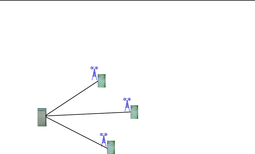
Technical Manual
Airbridge BTS3612A CDMA Base Station System Principle
Chapter 8 BTS Configuration
8-8
8.5.1 Star Networking
I. Application scope
Star networking is widely used, especially in the densely populated urban area. Start
networking is shown in the following figure.
BSC
BTS
BTS
BTS
E1
E1
E1
Figure 8-3 BTS star networking
II. Advantage
In the star networking mode, each BTS is directly connected with BSC via E1/T1
trunk line. The star networking is simple and allows convenient maintenance and
engineering.
Because the signals go through a few sections of links, the line is more reliable and
future expansion is easier.
III. Disavantage
Compared with other networking modes, star networking requires the largest number
of transmission lines.
IV. Implementation
The internal network of Huawei CDMA BSS is built on ATM platform. The logic links
of Abis interface, such as traffic link and signaling link, are carried by ATM links,
which is carried by E1/T1 links in IMA mode or UNI mode.

Technical Manual
Airbridge BTS3612A CDMA Base Station System Principle
Chapter 8 BTS Configuration
8-9
8.5.2 Chain Networking
I. Application scope
Chain networking of the BTS is shown in Figure 8-4. It is applicable to sparsely
populated stripe areas, e.g. along the highways and railways.
BSC BTS BTS
BTS
E1 E1 E1
Figure 8-4 BTS chain networking
II. Advantage
The adoption of the chain networking mode can scale down the expenditure on
transmission equipment, engineering construction, and lease of transmission links.
III. Disavantage
The signals go through more nodes in the chain networking mode, the line reliability
is poor.
The failure of upper-level BTS may affect the normal operation of lower-level BTS.
Maximum three-level cascading is allowed. That is, the nodes cascaded should not
exceed 3.
IV. Implementation
Chain networking is realized through the transmission trunk function of the BTS. The
transmission trunk is essentially Virtual Path (VP) switching. One BTS can be
configured with maximum 10 trunk links.
Note:
ATM switching is divided into two types: VP switching and Virtual Channel (VC)
switching. In the VP switching process, only the value of VPI is changed, while the
value of VCI is transmitted transparently. In the VC switching process, values of both
VPI and VCI remain unchanged. The VP is equivalent to a large channel, while the
VC a small one.
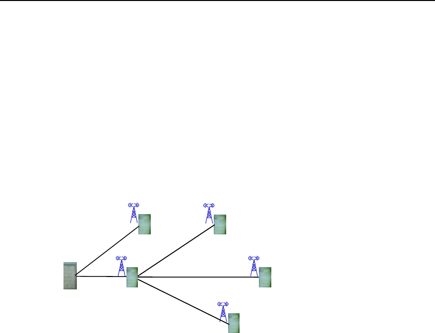
Technical Manual
Airbridge BTS3612A CDMA Base Station System Principle
Chapter 8 BTS Configuration
8-10
To configure a BTS trunk link, the forward/reverse BCIM No., forward/reverse link set
No., and forward/reverse VP No. should be properly configured.
8.5.3 Tree Networking
I. Application scope
Tree networking mode applies to the area where network structure, site and
subscriber distribution are complicated, such as the area where different types of
subscribers are not evenly distributed.
Tree networking is shown in Figure 8-5.
BSC
BTS
BTS
BTS
E1
E1
E1
BTS
BTS
E1
E1
Figure 8-5 BTS tree networking
II. Advantage
In the tree networking mode, less transmission lines are needed than in the star
networking mode.
III. Disavantage
In this mode, because signals go through many sections of links, the line reliability is
low, and engineering and maintenance are difficult.
The failure of upper-level BTS may affect the normal operation of lower-level BTS.
Expansion is not easy and may cause substantial network reconstruction.
The cascaded BTSs should not exceed 3 levels, i.e. the depth of the tree should not
exceed 3 layers.
IV. Implementation
The tree networking is in fact one application of the chain networking. For example,
the first-level BTS can be configured with multiple trunk links. These trunk links can

Technical Manual
Airbridge BTS3612A CDMA Base Station System Principle
Chapter 8 BTS Configuration
8-11
be allocated to each of the lower-level BTSs. (Note that these BTSs do not share the
same trunk lines.) The lower-level BTS can in turn allocate the trunk links to its own
lower-level BTSs. In this way, a tree network comes into being.
8.5.4 Fractional ATM Networking
I. Application scope
When the transmission resource is rather limited and the BTS capacity is not large,
BTS3612A supports the fractional ATM networking. That is, BTS only uses specific
timeslots in one or more E1/T1 links.
Fractional ATM networking is similar with the tree networking, except that in the
fractional ATM networking mode, only part of the timeslots of E1/T1 links are used.
II. Advantage
In this mode, transmission resource can be fully and flexibly utilized and thus related
cost can be reduced.
III. Disavantage
The capacity of BTS cannot be too large due to the restriction of transmission
resource. If the actual BTS capacity is more than what the transmission resource can
support, the call connected ratio will be affected.
The failure of upper-level BTS may affect the normal operation of lower-level BTS.
Expansion is not easy and may cause substantial network reconstruction.
IV. Implementation
BTS3612A can use the timeslot cross-connection function of QC52BCIM board to
implement the fractional ATM networking without the support of external equipment.
In practice, the timeslot cross-connection should be added to the upper-level BTS,
while the E1/T1 timeslots should be specified for the lower-level BTS by adding the
E1/T1 fractional ATM transmission link to this BTS.
8.5.5 Cascading with ODU3601Cs
I. Application scope
The ODU3601C is an outdoor soft BTS. By connecting ODU3601 to a master
BTS3612A in cascading mode, flexible coverage can be realized, including the indoor
coverage, underground coverage, and coverage of highways and railways.

Technical Manual
Airbridge BTS3612A CDMA Base Station System Principle
Chapter 8 BTS Configuration
8-12
II. Advantage
The satellite synchronization antenna & feeder is not required, which saves the
investment. This networking mode is suitable in the areas like the metro where the
satellite synchronization antenna & feeder cannot be easily installed.
Compared with repeater, ODU3601C supports the centralized management of the
upper-level BTS, which facilitates the network planning.
III. Disavantage
The failure of upper-level BTS may affect the normal operation of lower-level BTS.
IV. Implementation
The single-mode BRDM can be used for the cascading of ODU3601C. ODU3601C
can be configured as either in a certain sector of the master BTS, or as an
independent cell.
8.6 Typical Configurations
8.6.1 Overview
The BTS3612A support 450MHz band, 800MHz band and 1900MHz band, the typical
configurations for 450MHz band are listed as below (Without diversity transmission),
and the configurations for 800MHz band and 1900MHz band is similar to the
configurations for 450MHz band.
I. Single cabinet configuration
z Omni cell, 1~2 carriers (DFU or DDU adopted).
z 3 sectors, 1 carrier per sector (DFU adopted).
z 3 sectors, 1~2 carriers per sector (DDU adopted).
II. Combined configuration (with two cabinets)
z 3 sectors, 3~4 carriers per sector (CDU adopted).
z 6 sectors, 1~2 carriers per sector (DDU adopted).
Omni configuration is generally represented by O(X), where X indicates the number
of carriers. For example, O(2) represents the omni configuration with two carriers.
The three-sector directional configuration is represented by S(X/X/X), and the
six-sector one is represented by S(X/X/X/X/X/X).
The following will detail the typical configurations including O(2), S(2/2/2), and
S(4/4/4).
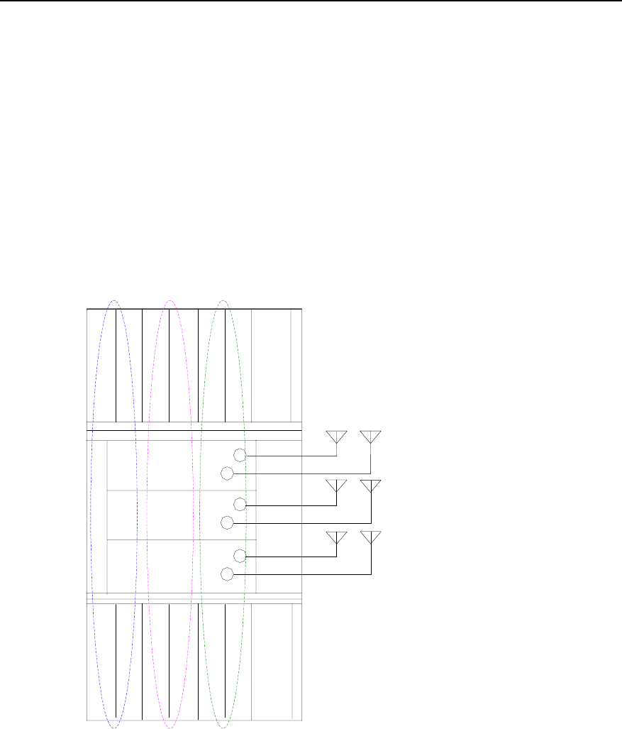
Technical Manual
Airbridge BTS3612A CDMA Base Station System Principle
Chapter 8 BTS Configuration
8-13
8.6.2 S(2/2/2) Configuration
The following is the configuration of BTS3612A for S(2/2/2) (i.e., 2 carriers % 3
sectors):
z Baseband boards: 1 BCIM, 1 BRDM, 1-2 BCKMs, and BCPM can be configured
according to actual requirement.
z Power modules: 3 PSUDC/DC modules, 9 PSUAC/DC modules.
z RF antennas: 2 uni-polarization directional antennas or 1 bi-polarization
directional antenna for each sector.
z RF modules: The configuration of the RF modules is shown in Figure 8-6, and
the logic connection of RF modules of one-sector is shown in Figure 8-7.
DDU0
DDU1
DDU2
B
H
P
A
1
B
T
R
M
1
B
H
P
A
3
B
T
R
M
3
B
H
P
A
5
B
T
R
M
5
R
L
D
U
1
B
H
P
A
0
B
T
R
M
0
B
H
P
A
2
B
T
R
M
2
B
H
P
A
4
B
T
R
M
4
R
L
D
U
0
A sector B sector C sector
A secto
B secto
r
C secto
r
Figure 8-6 S(2/2/2) RF configuration
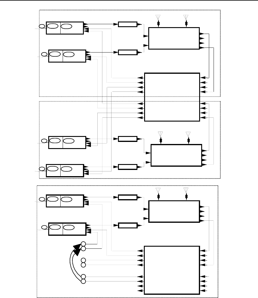
Technical Manual
Airbridge BTS3612A CDMA Base Station System Principle
Chapter 8 BTS Configuration
8-14
HPAU
PA_IN PA_OUT
HPAU
PA_IN PA_OUT
HPAU
PA_IN PA_OUT
HPAU
PA_IN PA_OUT
A_Main_RX_IN
A_Div._RX_IN
A_FWDCPL_IN
A_REVCPL_IN
B_Main_RX_IN
B_Div._RX_IN
B_FWDCPL_IN
B_REVCPL_IN
A_Rm1
A_Rm2
A_Rm3/B_Rm1
A_Rm4/B_Rm2
A_Rd1
A_Rd2
A_Rd3/B_Rd1
A_Rd4/B_Rd2
RLDU
TRXM
TX_RFm
RX_RFm
RX_RFd
BRCM
BIFM TX_RFd
TRXM
TX_RFm
RX_RFm
RX_RFd
BRCM
BIFM TX_RFd
TRXM
TX_RFm
RX_RFm
RX_RFd
BRCM
BIFM TX_RFd
TRXM
TX_RFm
RX_RFm
RX_RFd
BRCM
BIFM TX_RFd
HPAU
PA_IN PA_OUT
HPAU
PA_IN PA_OUT
A_Main_RX_IN
A_Div._RX_IN
A_FWDCPL_IN
A_REVCPL_IN
B_Main_RX_IN
B_Div._RX_IN
B_FWDCPL_IN
B_REVCPL_IN
A_Rm1
A_Rm2
A_Rm3/B_Rm1
A_Rm4/B_Rm2
A_Rd1
A_Rd2
A_Rd3/B_Rd1
A_Rd4/B_Rd2
RLDU
TRXM
TX_RFm
RX_RFm
RX_RFd
BRCM
BIFM TX_RFd
TRXM
TX_RFm
RX_RFm
RX_RFd
BRCM
BIFM TX_RFd
TX1_IN
TX2_IN
Main_ ANT Div._ ANT
Main_RX_OUT
Div._RX_OUT
FWDCPL_OUT
REVCPL_OUT
DDU
TX1_IN
TX2_IN
Main_ ANT Div._ ANT
Main_RX_OUT
Div._RX_OUT
FWDCPL_OUT
REVCPL_OUT
DDU
TX1_IN
TX2_IN
Main_ ANT Div._ ANT
Main_RX_OUT
Div._RX_OUT
FWDCPL_OUT
REVCPL_OUT
DDU
A sector
B sector
C sector
Figure 8-7 Logic connection of one-sector RF modules for S(2/2/2) configuration
8.6.3 S(4/4/4) Configuration
The S(4/4/4) (i.e., 4 carriers x 3 sectors) configuration requires two combined
cabinets, and the RLDU should receive two signals and process each signal in 1-4
modes. The following shows the configuration of the boards or modules.
z Baseband boards: 1 BCIM, 2 BRDM, 1-2 BCKMs, and BCPM can be configured
according to actual requirement.
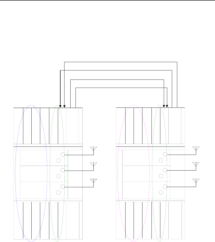
Technical Manual
Airbridge BTS3612A CDMA Base Station System Principle
Chapter 8 BTS Configuration
8-15
z Power modules: 3 PSUDC/DC modules, 9 PSUAC/DC modules.
z RF antennas: 2 uni-polarization directional antennas or 1 bi-polarization
directional antenna for each sector.
z RF modules: The configuration of the RF modules is shown in Figure 8-8, and
the logic connection of RF modules of one-sector is shown in Figure 8-9 and
Figure 8-10.
CDU0
CDU1
CDU2
B
H
P
A
1
B
T
R
M
1
B
H
P
A
3
B
T
R
M
3
B
H
P
A
5
B
T
R
M
5
R
L
D
U
1
B
H
P
A
0
B
T
R
M
0
B
H
P
A
2
B
T
R
M
2
B
H
P
A
4
B
T
R
M
4
R
L
D
U
0
Sector A
Sector A
Sector C
Sector A Sector C
f1,f2
f3,f4
f3,f4
CDU0
CDU1
CDU2
B
H
P
A
1
B
T
R
M
1
B
H
P
A
3
B
T
R
M
3
B
H
P
A
5
B
T
R
M
5
R
L
D
U
1
B
H
P
A
0
B
T
R
M
0
B
H
P
A
2
B
T
R
M
2
B
H
P
A
4
B
T
R
M
4
R
L
D
U
0
Sector B
Sector C
Sector B Sector C
f1,f2
f3,f4
f1,f2
Diversity receiving signal of f3 in Sector C
Diversity receiving signal of f4 in Sector C
Diversity receiving signal of f1 in Sector C
Diversity receiving signal of f2 in Sector C
Sector B
Figure 8-8 S(4/4/4) RF configuration
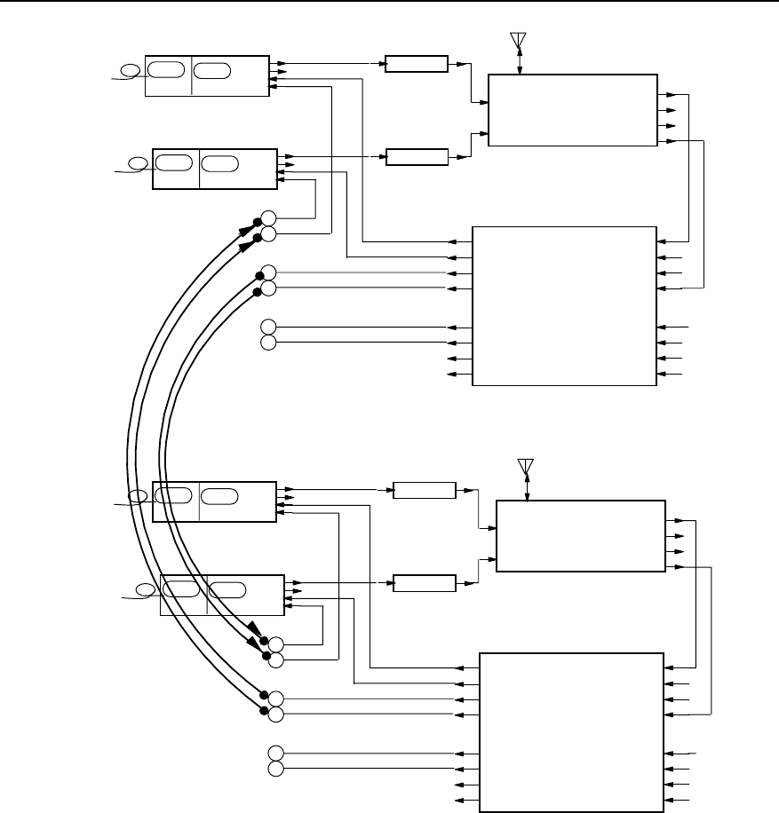
Technical Manual
Airbridge BTS3612A CDMA Base Station System Principle
Chapter 8 BTS Configuration
8-16
TX1_IN
TX2_IN
Main_ ANT Div._ ANT
Main_RX_OUT
Div._RX_OUT
FWDCPL_OUT
REVCPL_OUT
CDU
HPAU
PA_IN PA_OUT
HPAU
PA_IN PA_OUT
A_Main_RX_IN
A_Div._RX_IN
A_FWDCPL_IN
A_REVCPL_IN
B_Main_RX_IN
B_Div._RX_IN
B_FWDCPL_IN
B_REVCPL_IN
A_Rm1
A_Rm2
A_Rm3/B_Rm1
A_Rm4/B_Rm2
A_Rd1
A_Rd2
A_Rd3/B_Rd1
A_Rd4/B_Rd2
RLDU
TRXM
TX_RFm
RX_RFm
RX_RFd
BRCM
BIFM TX_RFd
TRXM
TX_RFm
RX_RFm
RX_RFd
BRCM
BIFM TX_RFd
TX1_IN
TX2_IN
Main_ ANT Div._ ANT
Main_RX_OUT
Div._RX_OUT
FWDCPL_OUT
REVCPL_OUT
CDU
HPAU
PA_IN PA_OUT
HPAU
PA_IN PA_OUT
A_Main_RX_IN
A_Div._RX_IN
A_FWDCPL_IN
A_REVCPL_IN
B_Main_RX_IN
B_Div._RX_IN
B_FWDCPL_IN
B_REVCPL_IN
A_Rm1
A_Rm2
A_Rm3/B_Rm1
A_Rm4/B_Rm2
A_Rd1
A_Rd2
A_Rd3/B_Rd1
A_Rd4/B_Rd2
RLDU
TRXM
TX_RFm
RX_RFm
RX_RFd
BRCM
BIFM TX_RFd
TRXM
TX_RFm
RX_RFm
RX_RFd
BRCM
BIFM TX_RFd
Figure 8-9 Logic connection of one-sector RF modules for S(4/4/4) configuration (The RF modules
belong to different cabinets)
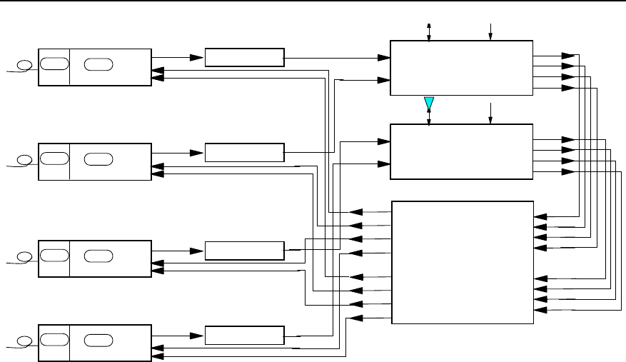
Technical Manual
Airbridge BTS3612A CDMA Base Station System Principle
Chapter 8 BTS Configuration
8-17
TX1_IN
TX2_IN
Main_ ANT Div._ ANT
Main_RX_OUT
Div._RX_OUT
FWDCPL_OUT
REVCPL_OUT
CDU
A_Main_RX_IN
A_Div._RX_IN
A_FWDCPL_IN
A_REVCPL_IN
B_Main_RX_IN
B_Div._RX_IN
B_FWDCPL_IN
B_REVCPL_IN
A_Rm1
A_Rm2
A_Rm3/B_Rm1
A_Rm4/B_Rm2
A_Rd1
A_Rd2
A_Rd3/B_Rd1
A_Rd4/B_Rd2
RLDU
TX1_IN
TX2_IN
Main_ ANT Div._ ANT
Main_RX_OUT
Div._RX_OUT
FWDCPL_OUT
REVCPL_OUT
CDU
BHPA
PA_IN PA_OUT
BHPA
PA_IN PA_OUT
BHPA
PA_IN PA_OUT
BHPA
PA_IN PA_OUT
BTRM
TX_RFm
RX_RFm
RX_RFd
BRCM
BIFM TX_RFd
BTRM
TX_RFm
RX_RFm
RX_RFd
BRCM
BIFM TX_RFd
BTRM
TX_RFm
RX_RFm
RX_RFd
BRCM
BIFM TX_RFd
BTRM
TX_RFm
RX_RFm
RX_RFd
BRCM
BIFM TX_RFd
Figure 8-10 Logic connection of one-sector RF modules for S(4/4/4) configuration (The RF modules belong to the same
cabinet)

Technical Manual
Airbridge BTS3612A CDMA Base Station System Principle
Appendix A Performance of Receiver and Transmitter
A-1
Appendix A Performance of Receiver and
Transmitter
The technical specifications of BTS receivers and transmitters comply with or surpass
all the performance requirements defined in the IS-97-D Recommended Minimum
Performance Standards for cdma2000 Spread Spectrum Base Stations.
A.1 Performance of Receiver
A.1.1 Frequency Coverage
z 450MHz band: 450 - 460MHz
z 800MHz band: 824 - 849MHz
z 1900MHz band: 1850 - 1910MHz
A.1.2 Access Probe Acquisition
The access probe failure ratio under the reliability of 90% is below the maximum values
listed in Table A-1:
Table A-1 Access probe failure ratio
Eb/N0 Per RF input point (dB) Maximum failure rate
5.5 50%
6.5 10%
A.1.3 R-TCH Demodulation Performance
I. Performance of R-TCH in Additive White Gaussian Noise (AWGN)
The demodulation performance of the Reverse Traffic Channel in AWGN (no fading or
multipath) environment is determined by the frame error rate (FER) at specified Eb/N0
value.
FER of 4 possible data rates should be calculated respectively. With 95% confidence,
the FER for each data rate does not exceed the two given FERs in Table A-2 to Table
A-9, which adopt the linear interpolation in the form of Log10(FER).

Technical Manual
Airbridge BTS3612A CDMA Base Station System Principle
Appendix A Performance of Receiver and Transmitter
A-2
Eb/N0 measurement value is decided by whichever is bigger of the Eb/N0 values in two
RF input ports.
Table A-2 Maximum FER of F-FCH or R-DCCH receiver in demodulation performance test under RC1
FER limits (%)
Data rate (bit/s) Lower limit Eb/N0 Upper limit Eb/N0
9600 3.0 @ 4.1dB 0.2 @ 4.7dB
4800 8.0 @ 4.1dB 1.0 @ 4.7dB
2400 23.0 @ 4.1dB 5.0 @ 4.7dB
1200 22.0 @ 4.1dB 6.0 @ 4.7dB
Table A-3 Maximum FER of F-FCH or R-DCCH receiver in demodulation performance test under RC2
FER limits (%)
Data rate (bit/s) Lower limit Eb/N0 Upper limit Eb/N0
14400 5.0 @ 3.2dB 0.2 @ 3.8dB
7200 6.3 @ 3.2dB 0.7 @ 3.2dB
3600 5.8 @ 3.2dB 1.0 @ 3.2dB
1800 3.5 @ 3.2dB 1.0 @ 3.2dB
Table A-4 Maximum FER of F-FCH or R-DCCH receiver in demodulation performance test under RC3
FER limit (%)
Data rate (bit/s) Lower limit Eb/N0 Upper limit Eb/N0
9600 2.3% @ 2.4 dB 0.3% @ 3.0 dB
4800 2.3% @ 3.8 dB 0.4% @ 4.4 dB
2700 2.5% @ 5.0 dB 0.5% @ 5.6 dB
1500 1.7% @ 7.0 dB 0.4% @ 7.6 dB
Table A-5 Maximum FER of R-SCH receiver in demodulation performance test under RC3
FER limit (%)
Data rate (bit/s) Lower limit Eb/N0 Upper limit Eb/N0
19200 9% @ 1.7 dB 1.7% @ 2.3 dB
38400 13% @ 1.4 dB 2.1% @ 2.0 dB

Technical Manual
Airbridge BTS3612A CDMA Base Station System Principle
Appendix A Performance of Receiver and Transmitter
A-3
FER limit (%)
Data rate (bit/s) Lower limit Eb/N0 Upper limit Eb/N0
76800 14% @ 1.3 dB 2.4% @ 1.9 dB
153600 14% @ 1.3 dB 2.4% @ 1.9 dB
307200 14% @ 1.8 dB 2.0% @ 2.4 dB
Table A-6 Maximum FER of R-SCH (Turbo Code) receiver in demodulation performance test under RC3
FER limit (%)
Data rate (bit/s) Lower limit Eb/N0 Upper limit Eb/N0
19200 20% @ 0.6 dB 0.9% @ 1.2 dB
38400 24% @ -0.1 dB 0.3% @ 0.5 dB
76800 30% @ -0.5 dB 0.2% @ 0.1 dB
153600 60% @ -0.9 dB 0.1% @ -0.3 dB
307200 90% @ -0.3 dB 0.1% @ 0.3 dB
Table A-7 Maximum FER of F-FCH or R-DCCH receiver in demodulation performance test under RC4
FER limit (%)
Data rate (bit/s) Lower limit Eb/N0 Upper limit Eb/N0
14400 2.4% @ 0.8 dB 0.3% @ 1.4 dB
7200 2.4% @ 3.1 dB 0.4% @ 3.7 dB
3600 1.7% @ 4.6 dB 0.3% @ 5.2 dB
1800 1.6% @ 6.6 dB 0.5% @ 7.2 dB
Table A-8 Maximum FER of R-SCH receiver of demodulation performance test under RC4
FER limit (%)
Data rate (bit/s) Lower limit Eb/N0 Upper limit Eb/N0
28800 10% @ 1.7 dB 1.9% @ 2.3 dB
57600 12% @ 1.6 dB 1.7% @ 2.2 dB
115200 14% @ 1.6 dB 2.0% @ 2.2 dB
230400 12% @ 1.7 dB 1.7% @ 2.3 dB

Technical Manual
Airbridge BTS3612A CDMA Base Station System Principle
Appendix A Performance of Receiver and Transmitter
A-4
Table A-9 Maximum FER of R-SCH (Turbo Code) receiver of demodulation performance test under RC4
FER limit (%)
Data rate (bit/s) Lower limit Eb/N0 Upper limit Eb/N0
28800 27% @ 0.7 dB 0.5% @ 1.3 dB
57600 28% @ 0.2 dB 0.2% @ 0.8 dB
115200 60% @ -0.2 dB 0.1% @ 0.4 dB
230400 33% @ -0.5 dB 0.1% @ 0.1 dB
II. R-TCH performance in multipath fading without Closed-Loop power control
The performance of the demodulation of the Reverse Traffic Channel in a multipath
fading environment is determined by the frame error rate (FER) at specified Eb/N0
value.
FER of 4 possible data rates should be calculated respectively. With 95% confidence,
the FER for each data rate shall not exceed that given by linear interpolation on a log10
(FER) scale between the two values given in Table A-13 and Table A-14.
The test value of Eb/N0 assumes the average value of Eb/N0 in two RF input ports.
During the test, the reverse service channel Eb/N0 of each RF input port adopted is
within the limits specified in Table A-12.
The configurations of standard channel simulator are given in Table A-10; and the
channel models of the R-TCH receiving performance test in multipath environment are
listed in Table A-11.
Table A-10 Standard channel simulator configuration
Standard
channel
Simulator
configuration
Speed Number
of Paths
Path 2 power
(corresponds
to path 1)
Path 3 power
(corresponds
to path 1)
Deferring
path 1
input
Deferring
path 2
input
Deferring
path 3
input
B 8km/h 2 0dB N/A 0µs 2.0
µs N/A
C 25km/h 1 N/A N/A 0µs N/A N/A
D 100km/h 3 0dB -3dB 0µs 2.0
µs 14.5
µs

Technical Manual
Airbridge BTS3612A CDMA Base Station System Principle
Appendix A Performance of Receiver and Transmitter
A-5
Table A-11 Channel models for the R-TCH receiving performance test
Case Channel Simulator configurations
B 2 (8 km/h, 2 paths)
C 3 (30 km/h, 1 path)
D 4 (100 km/h, 3 paths)
D2 4 (100 km/h, 3 paths)
Table A-12 Eb/N0 limits of R-TCH without closed-loop power control
Eb/N0 Limits (dB)
Rate aggregation Condition Lower limit Upper limit
B 11.1 11.7
C 11.2 11.8
D 8.8 9.4
RC1
D2 9.2 9.8
B 10.7 11.3
D 8.5 9.1
RC2
D2 8.9 9.5
Table A-13 Maximum FER of demodulation performance test of R-FCH or R-DCCH receiver under RC1
FER limits (%)
Case Data rate (bit/s)
Lower limit Eb/N0 Upper limit Eb/N0
9600 1.3 0.8
4800 1.4 0.9
2400 1.6 1.2
B
1200 1.3 0.9
9600 1.2 0.7
4800 1.4 0.9
2400 2.5 1.7
C
1200 2.0 1.4
9600 1.6 0.6
D 4800 2.6 1.2

Technical Manual
Airbridge BTS3612A CDMA Base Station System Principle
Appendix A Performance of Receiver and Transmitter
A-6
FER limits (%)
Case Data rate (bit/s)
Lower limit Eb/N0 Upper limit Eb/N0
2400 6.4 3.4
D 1200 5.6 3.5
9600 0.9 0.3
4800 1.6 0.7
2400 4.2 2.3
D2
1200 4.1 2.6
Table A-14 Maximum FER of demodulation performance test of R-FCH or R-DCCH receiver under RC2
FER limits (%)
Case Data rate (bit/s)
Lower limit Eb/N0 Upper limit Eb/N0
14400 1.3 0.8
7200 1.0 0.5
3600 0.7 0.4
B
1800 0.6 0.5
14400 1.7 0.6
7200 1.6 0.6
3600 1.5 0.9
D
1800 2.2 1.2
14400 0.9 0.3
7200 0.9 0.4
3600 1.1 0.6
D2
1800 1.5 0.9
III. Performance in multipath fading with Closed-Loop power control
The performance of the demodulation of the Reverse Traffic Channel in a multipath
fading environment is determined by the frame error rate (FER) at specified Eb/N0
value.
FER of 4 possible data rates needs to be calculated respectively. With 95% confidence,
the FER for each data rate shall not exceed that given by linear interpolation on a log10
scale between the two values given in Table A-16 and Table A-23.

Technical Manual
Airbridge BTS3612A CDMA Base Station System Principle
Appendix A Performance of Receiver and Transmitter
A-7
The test value of Eb/N0 assumes the average value of Eb/N0 tested on the two RF
input ports.
Table A-15 Channel models for the R-TCH receiving performance test
Condition Number of Channel Simulator configurations
A 1 (3 km/h, 1 path)
B 2 (8 km/h, 2 paths)
C 3 (30 km/h, 1 path)
D 4 (100 km/h, 3 path)
Table A-16 Maximum FER of demodulation performance test of R-FCH receiver under RC1
FER limits (%)
Condition Data rate (bit/s) Lower limit Eb/N0 Upper limit Eb/N0
9600 2.8% @ 5.9 dB 0.3 @ 6.5 dB
4800 7.6 @ 5.9 dB 2.2 @ 6.5 dB
2400 23.0 @ 5.9 dB 12.0 @ 6.5 dB
B
1200 22.0 @ 5.9 dB 14.0 @ 6.5 dB
9600 1.5 @ 7.1 dB 0.7 @ 7.7 dB
4800 8.0 @ 7.1 dB 4.8 @ 7.7 dB
2400 18.0 @ 7.1 dB 13.0 @ 7.7 dB
C
1200 16.0 @ 7.1 dB 12.0 @ 7.7 dB
Table A-17 Maximum FER of demodulation performance test of R-FCH receiver under RC2
FER limits (%)
Case Data rate (bit/s)
Lower limit Eb/N0 Upper limit Eb/N0
14400 2.8 @ 5.2 dB 0.4 @ 5.8 dB
7200 4.7 @ 5.2 dB 1.3 @ 5.8 dB
3600 8.7 @ 5.2 dB 4.6 @ 5.8 dB
B
1800 15.0 @ 5.2 dB 9.8 @ 5.8 dB
14400 1.3 @ 7.7 dB 0.7 @ 8.3 dB
7200 3.2 @ 7.7 dB 1.8 @ 8.3 dB
3600 4.7 @ 7.7 dB 3.5 @ 8.3 dB
C
1800 5.2 @ 7.7 dB 3.9 @ 8.3 dB

Technical Manual
Airbridge BTS3612A CDMA Base Station System Principle
Appendix A Performance of Receiver and Transmitter
A-8
Table A-18 Maximum FER of demodulation performance test of R-FCH or R-DCCH receiver under RC3
FER limits (%)
Case Data rate (bit/s)
Lower limit Eb/N0 Upper limit Eb/N0
9600 (20 ms) 2.4% @ 3.4 dB 0.5% @ 4.0 dB
4800 2.0% @ 4.4 dB 0.5% @ 5.0 dB
2700 1.8% @ 5.6 dB 0.5% @ 6.2 dB
A
1500 1.8% @ 7.2 dB 0.6% @ 7.8 dB
9600 (20 ms) 2.0% @ 3.9 dB 0.5% @ 4.5 dB
4800 2.0% @ 4.9 dB 0.5% @ 5.5 dB
2700 1.8% @ 6.1 dB 0.5% @ 6.7 dB
B
1500 1.7% @ 7.8 dB 0.5% @ 8.4 dB
9600 (20 ms) 1.5% @ 5.2 dB 0.6% @ 5.8 dB
4800 1.5% @ 6.1 dB 0.6% @ 6.7 dB
2700 1.4% @ 7.2 dB 0.6% @ 7.8 dB
C
1500 1.4% @ 8.8 dB 0.6% @ 9.4 dB
9600 (20 ms) 2.0% @ 4.7 dB 0.5% @ 5.3 dB
4800 2.0% @ 5.7 dB 0.5% @ 6.3 dB
2700 1.8% @ 6.9 dB 0.5% @ 7.5 dB
D
1500 1.7% @ 8.5 dB 0.5% @ 9.1 dB
Table A-19 Maximum FER of demodulation performance test of R-SCH (Turbo Code) receiver under RC3
FER limits (%)
Case Data rate (bit/s)
Lower limit Eb/N0 Upper limit Eb/N0
307200 10% @ 2.6 dB 2.0% @ 3.2 dB
153600 10% @ 2.6 dB 2.0% @ 3.2 dB
76800 10% @ 2.1 dB 2.4% @ 2.7 dB
38400 9.0% @ 2.4 dB 2.4% @ 3.0 dB
B
19200 9.0% @ 2.8 dB 2.5% @ 3.4 dB

Technical Manual
Airbridge BTS3612A CDMA Base Station System Principle
Appendix A Performance of Receiver and Transmitter
A-9
Table A-20 Maximum FER of demodulation performance test of R-SCH (Turbo Code) receiver under RC3
FER limits (%)
Case Data rate (bit/s)
Lower limit Eb/N0 Upper limit Eb/N0
307200 15% @ 0.8 dB 1.8% @ 1.4 dB
153600 12% @ 0.2 dB 2.0% @ 0.8 dB
76800 10% @ 0.7 dB 2.0% @ 1.3 dB
38400 10% @ 1.3 dB 2.0% @ 1.9 dB
B
19200 10% @ 2.1 dB 2.5% @ 2.7 dB
Table A-21 Maximum FER of demodulation performance test of R-FCH or R-DCCH receiver under RC4
FER limits (%)
Case Data rate (bit/s)
Lower limit Eb/N0 Upper limit Eb/N0
14400 2.2% @ 3.2 dB 0.4% @ 3.8 dB
7200 1.9% @ 3.9 dB 0.4% @ 4.5 dB
3600 1.9% @ 5.1 dB 0.5% @ 5.7 dB
A
1800 1.8% @ 7.0 dB 0.5% @ 7.6 dB
14400 2.0% @ 3.8 dB 0.4% @ 4.4 dB
7200 2.0% @ 4.3 dB 0.5% @ 4.9 dB
3600 1.8% @ 5.6 dB 0.5% @ 6.2 dB
B
1800 1.8% @ 7.5 dB 0.5% @ 8.1 dB
14400 1.6% @ 5.1 dB 0.6% @ 5.7 dB
7200 1.7% @ 5.6 dB 0.7% @ 6.2 dB
3600 1.5% @ 6.7 dB 0.6% @ 7.3 dB
C
1800 1.6% @ 8.4 dB 0.7% @ 9 dB
14400 2.0% @ 4.6 dB 0.5% @ 5.2 dB
7200 2.0% @ 5.1 dB 0.5% @ 5.7 dB
3600 1.9% @ 6.3 dB 0.5% @ 6.9 dB
D
1800 1.8% @ 8.1 dB 0.6% @ 8.7 dB

Technical Manual
Airbridge BTS3612A CDMA Base Station System Principle
Appendix A Performance of Receiver and Transmitter
A-10
Table A-22 Maximum FER of demodulation performance test of R-SCH(Turbo Code) receiver under RC4
FER limits (%)
Case Data rate (bit/s)
Lower limit Eb/N0 Upper limit Eb/N0
230400 10% @ 2.4 dB 1.4% @ 3.0 dB
115200 9.0% @ 2.5 dB 2.3% @ 3.1 dB
57600 9.0% @ 2.6 dB 2.2% @ 3.2 dB
B
28800 7.5% @ 2.8 dB 2.5% @ 3.4 dB
Table A-23 Maximum FER of demodulation performance test of R-SCH (Turbo Code) receiver under RC4
FER limits (%)
Case Data rate
(bit/s) Lower limit Eb/N0 Upper limit Eb/N0
230400 10% @ 1.1 dB 2.0% @ 1.7 dB
115200 10% @ 1.0 dB 1.5% @ 1.7 dB
57600 11% @ 1.5 dB 1.8% @ 2.1 dB
B
28800 10% @ 2.1 dB 2.0% @ 2.7 dB
A.1.4 Receiving Performance
I. Sensitivity
z 450MHz band and 1900MHz band
The R-TCH FER shall be <1.0% with 95% confidence when -126dBm/1.23MHz CDMA
RC3 signal level is inputted at BTS RF main and diversity input ports.
z 800MHz band
The R-TCH FER shall be <1.0% with 95% confidence when -127dBm/1.23MHz CDMA
RC3 signal level is inputted at BTS RF main and diversity input ports.
II. Receiver dynamic range
z 450MHz band and 1900MHz band
The R-TCH FER shall be 1.0% or less with 95% confidence when
-126dBm/1.23MHz~-65dBm/1.23MHz CDMA signal level is inputted at BTS RF main
and diversity input ports.
z 800MHz band

Technical Manual
Airbridge BTS3612A CDMA Base Station System Principle
Appendix A Performance of Receiver and Transmitter
A-11
The R-TCH FER shall be 1.0% or less with 95% confidence when
-127dBm/1.23MHz~-65dBm/1.23MHz CDMA signal level is inputted at BTS RF main
and diversity input ports.
III. Single-tone desensitization
z 450MHz band
Input the single-tone interference deviated from the center frequency at the BTS RF
input port: when the single-tone interference deviates from the center frequency
+900kHz and -900kHz, the input single-tone interference power is 87dB higher than the
output power of the mobile station simulator.
When R-TCH FER maintains <1.5%, the output power of mobile station simulator
changes less than 3dB whether there is single-tone interference or not.
z 800MHz band
Input the single-tone interference deviated from the center frequency at the BTS RF
input port: when the single-tone interference deviates from the center frequency about
+750kHz and -750kHz, the input single-tone interference power is 50dB higher than the
output power of the mobile station simulator; when the single-tone interference
deviates from the center frequency +900kHz and -900kHz, the input single-tone
interference power is 87dB higher than the output power of the mobile station simulator.
When R-TCH FER maintains <1.5%, the output power of mobile station simulator
changes less than 3dB whether there is single-tone interference or not.
z 1900MHz band
Input the single-tone interference deviated from the center frequency at the BTS RF
input port: when the single-tone interference deviates from the center frequency
+1.25MHz and -1.25MHz, the input single-tone interference power is 80dB higher than
the output power of the mobile station simulator.
When R-TCH FER maintains <1.5%, the output power of mobile station simulator
changes less than 3dB whether there is single-tone interference or not.
IV. Intermodulation spurious response attenuation
z 450MHz band and 800MHz band
Input two single-tone interference of center frequency at the BTS RF input port: both
deviate from the center frequency +900kHz and +1700kHz respectively, and -900kHz
and -1700kHz respectively, the input single-tone interference power is 72dB higher
than the output power of the mobile station simulator.
When R-TCH FER keeps <1.5%, the output power of the mobile station simulator
changes less than 3dB whether there are two single-tone interference or no
interference.

Technical Manual
Airbridge BTS3612A CDMA Base Station System Principle
Appendix A Performance of Receiver and Transmitter
A-12
z 1900MHz band
Input two single-tone interference of center frequency at the BTS RF input port: both
deviate from the center frequency +1.25MHz and +2.05MHz respectively, and
-1.25MHz and -2.05MHz respectively.
When R-TCH FER keeps <1.5%, the output power of the mobile station simulator
changes less than 3dB whether there are two single-tone interference or no
interference.
V. Adjacent channel selectivity
The output power of the mobile station simulator shall increase by no more than 3 dB
and the FER shall be less than 1.5% with 95% confidence.
A.1.5 Limitations on Emissions
I. Conducted spurious emissions
At BTS RF input port, the conducted spurious emissions within the BTS receiving
frequency range is <-80dBm/30kHz.
At BTS RF input port, the conducted spurious emissions within the transmitting
frequency range is <-60dBm/30kHz.
At BTS RF input port, the conducted spurious emissions within other frequency range
of 0~6GHz is <-47dBm/30kHz.
II. Radiated spurious emissions
The performance is in compliant with local radio specifications.
A.1.6 Received Signal Quality Indicator (RSQI)
RSQI is defined as the signal-to-noise ratio Eb/N0, where Eb is the energy per bit
including the pilot and power control overhead and N0 is the total received
noise-pulse-interference power in the CDMA bandwidth including the interference from
other subscribers.
The RSQI report values of the BTS are list in Table A-24.

Technical Manual
Airbridge BTS3612A CDMA Base Station System Principle
Appendix A Performance of Receiver and Transmitter
A-13
Table A-24 RSQI range
Eb/N0 (dB) per input port Minimum Acceptable Report
Value Maximum Acceptable Report
Value
4 10 18
5 12 20
6 14 22
7 16 24
8 18 26
9 20 28
10 22 30
11 24 32
12 26 34
13 28 36
14 30 38
A.2 Performance of Transmitter
A.2.1 Frequency Requirements
I. Frequency coverage
z 450MHz band: 460 - 470MHz
z 800MHz band: 869 - 894MHz
z 1900MHz band: 1930 - 1990MHz
II. Frequency tolerance
Within the working temperature range, the average difference between the actual
carrier frequency of CDMA transmit sector and the carrier frequency of the dedicated
transmit sector is less than !5%10-8(!0.05ppm)of the designated frequency.
A.2.2 Modulation Requirements
I. Synchronization and timing
Time tolerance for pilot frequency: The pilot time alignment error should be less than 3
µs and shall be less than 10 µs. For BTSs supporting multiple simultaneous CDMA

Technical Manual
Airbridge BTS3612A CDMA Base Station System Principle
Appendix A Performance of Receiver and Transmitter
A-14
Channels, the pilot time tolerance of all CDMA Channels radiated by a BTS shall be
within ±1 µs of each other.
Time tolerance of pilot channel and other code-division channels: in the same CDMA
channel, time error between the pilot channel and other forwarding code-division
channels is <!50ns.
The phase differences between the Pilot Channel and all other code channels sharing
the same Forward CDMA Channel should not exceed 0.05 radians and shall not
exceed 0.15 radians.
II. Waveform quality
The normalized cross correlation coefficient, ρ, shall be greater than 0.912 (excess
power < 0.4 dB)..
A.2.3 RF Output Power
I. Total power
Total power is the mean power delivered to a load with resistance equal to the nominal
load impedance of the transmitter.. The total power of this system is +43dBm (20W),
the deviation in all kinds of environmental conditions shall not exceed +2dB and -4dB.
II. Pilot power
The Pilot Channel power to total power ratio shall be within ±0.5 dB of the configured
value.
III. Code domain power
For RC1and RC2, the code domain power in each inactive Wn64 channel shall be 27 dB
or more below the total output power.
For RC3 and RC4, the code domain power in each inactive Wn128 channel shall be 30
dB or more below the total output power.
For RC1 and RC2, the code domain power in each inactive Wn256 channel shall be 33
dB or more below the total output power of each carrier.

Technical Manual
Airbridge BTS3612A CDMA Base Station System Principle
Appendix A Performance of Receiver and Transmitter
A-15
A.2.4 Limitations on Emissions
I. Conducted spurious emissions
The requirements on Conducted Spurious Emissions vary with frequency bands, as
shown in Table A-25 and Table A-26. Local radio requirements should also be
observed.
Table A-25 Conducted Spurious Emissions Performance (450MHz band and 800MHz band)
Offset from carrier central frequency Spurious requirement
750 kHz~1.98 MHz -45 dBc / 30 kHz
1.98 MHz~4.00 MHz
-60 dBc / 30 kHz; Pout ≥ 33 dBm
-27 dBm / 30 kHz; 28 dBm ≤ Pout < 33 dBm
-55 dBc / 30 kHz; Pout < 28 dBm
> 4.00 MHz
(ITU Class A Requirement)
-13 dBm / 1 kHz;
-13 dBm / 10 kHz;
-13 dBm/100 kHz;
-13 dBm / 1 MHz;
9 kHz < f < 150 kHz
150 kHz < f < 30 MHz
30 MHz < f < 1 GHz
1 GHz < f < 5 GHz
> 4.00 MHz
(ITU Class B Requirement)
-36 dBm / 1 kHz;
-36 dBm / 10 kHz;
-36 dBm/100 kHz;
-30 dBm / 1 MHz;
9 kHz < f < 150 kHz
150 kHz < f < 30 MHz
30 MHz < f < 1 GHz
1 GHz < f < 12.5 GHz
Table A-26 Conducted Spurious Emissions Performance (1900MHz band)
Offset from carrier central frequency Spurious requirement
885 kHz~1.25 MHz -45 dBc / 30 kHz
1.25 MHz~1.98 MHz
-60 dBc / 30 kHz; Pout ≥ 33 dBm
-27 dBm / 30 kHz; 28 dBm ≤ Pout < 33 dBm
-55 dBc / 30 kHz; Pout < 28 dBm
1.98 MHz~2.25 MHz
-55dBc/30kHz, Poutú33dBm
-22dBm/30kHz, 28dBm ≤ Pout < 33dBm
-50dBc/30kHz, Pout < 28dBm
2.25 MHz~4.00 MHz -13dBm/1MHz
> 4.00 MHz
(ITU Class A Requirement)
-13 dBm / 1 kHz;
-13 dBm / 10 kHz;
-13 dBm/100 kHz;
-13 dBm / 1 MHz;
9 kHz < f < 150 kHz
150 kHz < f < 30 MHz
30 MHz < f < 1 GHz
1 GHz < f < 5 GHz

Technical Manual
Airbridge BTS3612A CDMA Base Station System Principle
Appendix A Performance of Receiver and Transmitter
A-16
II. Radiated spurious emissions
The performance is in compliant with local radio specifications.

Technical Manual
Airbridge BTS3612A CDMA Base Station System Principle
Appendix B EMC Performance
B-1
Appendix B EMC Performance
ETSI EN 300 386 Electromagnetic Compatibility and Radio Spectrum Matters (ERM);
Telecommunication network Equipment; ElectroMagnetic Compatibility (EMC)
Requirements are the international EMC standards.
The EMC performance of BTS3612A complies with ETSI EN 300 386 V1.2.1 (2000-03).
They are described in two aspects: ElectroMagnetic Interference (EMI) and
ElectroMagnetic Sensitivity (EMS).
B.1 EMI Performance
I. Conductive Emission (CE) at DC input/output port
CE indices are listed in Table B-1.
Table B-1 CE indices at -48V port
Threshold (dB µV)
Frequency range Average Quasi-peak
0.15 ~ 0.5MHz
0.5 ~ 5MHz
5 ~ 30MHz
56~46
46
50
66~56
56
60
II. Radiated Emission (RE)
RE indices are listed in Table B-2.
Table B-2 RE indices
Band (MHz) Threshold of quasi-peak (dB µV/m)
30 ~ 1000 61.5
1000 ~ 12700 67.5
Note:
Test field is arranged according to ITU-R 329-7 [1].

Technical Manual
Airbridge BTS3612A CDMA Base Station System Principle
Appendix B EMC Performance
B-2
B.2 EMS Performance
I. RF EM field immunity (80~1000MHz)
RF EM field immunity indices are listed in Table B-3.
Table B-3 RF EM field immunity indices
Port Level Performance class
Whole cabinet 3V/m A
Note:
Test method complies with IEC1000-4-3 [9].
II. Voltage dips and short interruptions immunity
Among all test items of EMS, the requirement for continuous interference immunity is
class A and the requirement for transient interference immunity is class B.
Requirements for voltage dips and short interruptions is shown in Table B-4.
Table B-4 Voltage dips and short interruptions indices
Port Test level Performance class
Dip 30%
Duration: 10ms A
Dip: 60%
Duration: 100ms
With backup power: A
With no backup power: The communication link need
not be maintained. It can be re-created and the
subscriber data can be lost.
AC port
Dip: over95%
Duration: 5000ms
With backup power: A
With no backup power: The communication link need
not be maintained. It can be re-created and the
subscriber data can be lost.
Note:
Test method complies with IEC61000-4-11 [13].

Technical Manual
Airbridge BTS3612A CDMA Base Station System Principle
Appendix B EMC Performance
B-3
III. Electrostatic Discharge (ESD) immunity
ESD immunity indices are shown in Table B-5.
Table B-5 ESD immunity indices
Discharge mode Level Performance class
Contact 2kV, 4kV B
Air 2kV, 4kV, 8kV B
Note:
Test method complies with IEC 61000-4-2 [5].
In addition to the protection measures specified in the user's documents, ESD measures should be taken
to all exposed surface of equipment to be tested.
IV. RF induced currents
In CDMA equipment, the port where a cable of more than 1 meter may be connected to,
including control port, DC input/output port and the input/output port of the connection
line when cabinets are combined, should satisfy the requirements for RF induced
currents. The indices are shown in Table B-6.
Table B-6 Induced currents indices
Port Voltage level Performance class
DC line port
AC line port
Signal line port and control line port
3V A
Note:
Test method complies with IEC61000-4-6 [9].
V. Surge immunity
For CDMA equipment, the DC power input port, indoor signal line of more than 3 m,
control line (such as E1 trunk line, serial port line) and the cable that may be led out to

Technical Manual
Airbridge BTS3612A CDMA Base Station System Principle
Appendix B EMC Performance
B-4
the outdoor should all satisfy the requirements for surge immunity. The indices are
shown in Table B-7.
Table B-7 Surge immunity indices
Port Level Performance class
AC port Line~line, 2kV
Line~ground, 4kV B
Control line, signal line Line~line, 0.5kV
Line~ground, 1kV B
Control line, signal line (outdoors) Line~line, 1kV
Line~ground, 2kV B
Note:
The test method complies with IEC61000-4-5 [11].
VI. Common-mode fast transient pulse immunity
The signal & data line between CDMA cabinets and that connected with other systems
(such as E1 trunk line), control line and cable connected to DC input/output port, should
satisfy the requirements for fast transient pulse immunity. The indices are shown in
Table B-8.
Table B-8 Common-mode fast transient pulse immunity indices
Port Level Performance class
Signal control line port 0.5kV B
DC line input/output port 1kV B
AC line input port 2kV B

Technical Manual
Airbridge BTS3612A CDMA Base Station System Principle
Appendix B EMC Performance
B-5
Note:
Performance class A: BTS can withstand the test without any damage and it can run normally in the
specified range. There is not any change in the software or data (all data in the storage or the data being
processed) related to the tested switching equipment. Equipment performance is not lowered.
Performance class B: BTS can withstand the test without any damage. There is no change in the
software or the data in storage. Communication performance is lowered a little, but in the tolerance (as
defined for different products). The existing communication link is not interrupted. After the test, the
equipment can recover to the normal status before the test automatically without any interference of the
operator.
Performance class C: Some functions of BTS are lost temporarily during the test, but they will recover to
normal performance in a specific period after the test (normally the shortest time needed for system
reboot). There is no physical damage or system software deterioration.
Performance class R: After the test, there is no physical damage or fault (including software corruption)
with BTS. Protection equipment damage caused by external interference signal is acceptable. When the
protection equipment is replaced and the running parameters are re-configured, the equipment can
operate normally.

Technical Manual
Airbridge BTS3612A CDMA Base Station System Principle
Appendix C Environment Requirements
C-1
Appendix C Environment Requirements
The environment requirements of BTS3612A involve storage, transportation, and
operation environments. These requirements are specified based on the following
standards:
z ETS 300019 Equipment Engineering (EE); Environmental conditions and
environmental tests for telecommunications equipment
z IEC 60721 Classification of environmental conditions
C.1 Storage Environment
I. Climate environment
Table C-1 Requirements for climate environment
Item Range
Altitude ñ5000m
Air pressure 70kPa~106kPa
Temperature -40~+70 Celsius degree
Temperature change rate ñ1 Celsius degree/min
Relative humidity 10%~100%
Solar radiation ñ1120W/s²
Thermal radiation ñ600W/s²
Wind speed ñ30m/s
Rain Drippings
II. Biotic environment
z No microorganism like fungal or mould multiplied around or inside.
z Free from the attack of rodential animals (such as rats).
III. Air cleanness
z No explosive, electrically/magnetically conductive, or corrosive particles around.
z The density of physically active substances shall meet the requirements listed in
Table C-2.

Technical Manual
Airbridge BTS3612A CDMA Base Station System Principle
Appendix C Environment Requirements
C-2
Table C-2 Requirements for the density of physically active substances
Substance Unit Density
Suspending dust mg/m³ ñ5.00
Falling dust mg/m²∙h ñ20.0
Sands mg/m³
ñ300
Note:
Suspending dust: diameter ñ75m
Falling dust: 75mñdiameterñ150m
Sands: 150mñdiameterñ1,000m
z The density of chemically active substances shall meet the requirements listed in
Table C-3.
Table C-3 Requirements for the density of chemically active substances
Substance Unit Density
SO2 mg/m³
ñ0.30
H2S mg/m³
ñ0.10
NO2 mg/m³
ñ0.50
NH3 mg/m³
ñ1.00
Cl2 mg/m³
ñ0.10
HCl mg/m³
ñ0.10
HF mg/m³
ñ0.01
O3 mg/m³
ñ0.05
IV. Mechanical stress
Table C-4 Requirements for mechanical stress
Item Sub-item Range
Displacement ñ7.0mm -
Acceleration - ñ20.0m/s²
Sinusoidal vibration
Frequency range 2~9Hz 9~200Hz
Impact response
spectrum II ñ250m/s²
Unsteady impact
Static load capability ñ5kPa

Technical Manual
Airbridge BTS3612A CDMA Base Station System Principle
Appendix C Environment Requirements
C-3
Item Sub-item Range
Note:
Impact response spectrum: The max. acceleration response curve generated by the equipment under
the specified impact excitation. Impact response spectrum II refers to the semi sinusoidal impact
response spectrum whose duration is 6ms.
Static load capability: The capability of the equipment in package to bear the pressure from the top in
normal pile-up method.
C.2 Transportation Environment
I. Climate environment
Table C-5 Requirements for climate environment
Item Range
Altitude ñ5,000m
Air pressure 70kPa~106kPa
Temperature -40~+70 Celsius degree
Temperature change rate ñ3 Celsius degree/min
Relative humidity 5%~100%
Solar radiation ñ1,120W/s²
Thermal radiation ñ600W/s²
Wind speed ñ30m/s
II. Biotic environment
z No microorganism like fungal or mould multiplied around or inside.
z Free from the attack of rodential animals (such as rats).
III. Air cleanness
z No explosive, electrically/magnetically conductive, or corrosive particles around.
z The density of physically active substances shall meet the requirements listed in
Table C-6.
Table C-6 Requirements for the density of physically active substances
Substance Unit Density
Suspending dust mg/m³ No requirement

Technical Manual
Airbridge BTS3612A CDMA Base Station System Principle
Appendix C Environment Requirements
C-4
Substance Unit Density
Falling dust mg/m²∙h ñ3.0
Sands mg/m³
ñ100
Note:
Suspending dust: diameter ñ75m
Falling dust: 75mñdiameterñ150m
Sands: 150mñdiameterñ1,000m
z The density of chemically active substances shall meet the requirements listed in
Table C-7.
Table C-7 Requirements for the density of chemically active substances
Substance Unit Density
SO2 mg/m³
ñ0.30
H2S mg/m³
ñ0.10
NO2 mg/m³
ñ0.50
NH3 mg/m³
ñ1.00
Cl2 mg/m³
ñ0.10
HCl mg/m³
ñ0.10
HF mg/m³
ñ0.01
O3 mg/m³
ñ0.05
IV. Mechanical stress
Table C-8 Requirements for mechanical stress
Item Sub-item Range
Displacement ñ7.5mm - -
Acceleration -
ñ20.0m/s² ñ40.0m/s²
Sinusoidal
vibration
Frequency range 2~9Hz 9~200Hz 200~500Hz
Acceleration spectrum density 10m²/s³ 3m²/s³ 1m²/s³
Random
vibration Frequency range 2~9Hz 9~200Hz 200~500Hz
Impact response spectrum II ñ300m/s²
Unsteady
impact Static load capability ñ10kPa

Technical Manual
Airbridge BTS3612A CDMA Base Station System Principle
Appendix C Environment Requirements
C-5
Item Sub-item Range
Note:
Impact response spectrum: The max. acceleration response curve generated by the equipment under
the specified impact excitation. Impact response spectrum II refers to the semi sinusoidal impact
response spectrum whose duration is 6ms.
Static load capability: The capability of the equipment in package to bear the pressure from the top in
normal pile-up method.
C.3 Operation Environment
I. Climate environment
Table C-9 Temperature and humidity requirements
Temperature
Product Long-term Short-term
Relative humidity
BTS3612A -40~+55 Celsius degree -40~+45 Celsius degree 5%~100%
Note:
The measurement point of temperature and humidity is 2 m above the floor and 0.4 m in front of the
equipment, when there are no protective panels in front of or behind the cabinet.
Table C-10 Other climate environment requirements
Item Range
Altitude ñ4000m
Air pressure 70kPa~106kPa
Temperature change rate ñ5 Celsius degree/min
Solar radiation ñ1120W/m²
Rain ñ12.5L/min±0.625 L/min (IPX5)
Wind speed ñ50m/s
II. Biotic environment
z No microorganism like fungal or mould multiplied around or inside.
z Free from the attack of rodential animals (such as rats).

Technical Manual
Airbridge BTS3612A CDMA Base Station System Principle
Appendix C Environment Requirements
C-6
III. Air cleanness
z No explosive, electrically/magnetically conductive, or corrosive particles around.
z The density of physically active substances shall meet the requirements listed in
Table C-11.
Table C-11 Requirements for the density of physically active substances
Substance Unit Density
Suspending dust mg/m³ ñ5
Falling dust mg/m²∙h ñ20
Sands mg/m³ ñ300
Note:
Suspending dust: diameter ñ75m
Falling dust: 75mñdiameterñ150m
Sands: 150mñdiameterñ1,000m
z The density of chemically active substances shall meet the requirements listed in
Table C-12.
Table C-12 Requirements for the density of chemically active substances
Substance Unit Density
SO2 mg/m³ ñ0.30
H2S mg/m³ ñ0.10
NH3 mg/m³ ñ1.00
Cl2 mg/m³ ñ0.10
HCl mg/m³ ñ0.10
HF mg/m³ ñ0.01
O3 mg/m³ ñ0.05
NO2 mg/m³ ñ0.5

Technical Manual
Airbridge BTS3612A CDMA Base Station System Principle
Appendix C Environment Requirements
C-7
IV. Mechanical stress
Table C-13 Requirements for mechanical stress
Item Sub-item Range
Displacement ñ3.5mm -
Acceleration - ñ10.0m/s²
Sinusoidal vibration
Frequency range 2~9Hz 9~200Hz
Impact response
spectrum II ñ100m/s²
Unsteady impact
Static load capability 0
Note:
Impact response spectrum: The max. acceleration response curve generated by the equipment under
the specified impact excitation. Impact response spectrum II refers to the semi sinusoidal impact
response spectrum whose duration is 6ms.
Static load capability: The capability of the equipment in package to bear the pressure from the top in
normal pile-up method.

Technical Manual
Airbridge BTS3612A CDMA Base Station System Principle
Appendix D Electromagnetic Radiation
D-1
Appendix D Electromagnetic Radiation
D.1 Introduction
The BTS has RF radiation (Radiation Hazard). Although there is no scientific evidence
of possible health risks to persons living near the BTSs, some recommendations are
giving below for the installation and operation of BTS.
Maximum Permissible Exposure (MPE) limits are specified by the Federal
Communications Commission (FCC). FCC CFR part 1, subpart I, section 1.1307
requires operator to perform a Enviromenta Assemessmet (EA).
Equipment listed in the table 1 of before mentioned part are subjected to routine
environmental evaulation. For facilities and operations licensed under part 22,
licensees and manufactuere are required tto ensure that their facility and equipment
comply with IEEE C95.1-1991.
The objective of the Environmental Evaluation is to ensure that human exposure to RF
energy does not go beyond the maximum permissible levels stated in the standard.
Therefore certain sites do not require an evaluation by nature of its design. It could be
that the antennas are placed high enough thereby resulting in extremely low RF fields
by the time it reaches areas that would be accessible to people.
Environmental evaluations are required, for Paging and Cellular Radiotelephone
Services, Part 22 Subpart E and H.
z Non-rooftop antennas: height of radiation center < 10m above ground level and
total power of all channels > 1000 W ERP (1640 W EIRP)
z Rooftop antennae: total power of all channels > 1000 W ERP (1640 W EIRP)
D.2 Maximum Permissible Exposure
Maximum Permissible Exposure (MPE) refers to the RF energy that is acceptable for
human exposure. It is broken down into two categories, Controlled and Uncontrolled.
Controlled limits are used for persons such as installers and designers that are in
control of the hazard and exposed to energy for limited amounts of time per day.
Occupational/controlled limits apply in situations in which are persons are exposed as a
consequence of their employment provided those persons are fully aware of the
potential for exposure and can exercise control over their exposure. Limits for
occupational/controlled exposure also apply in situations when an individual is

Technical Manual
Airbridge BTS3612A CDMA Base Station System Principle
Appendix D Electromagnetic Radiation
D-2
transient through a location where occupational/controlled limits apply provided he or
she is made aware of the potential for exposure.
Uncontrolled limits are used for general public. Uncontrolled exposure apply in
situations is which the general public may be exposed, or in which persons that are
exposed as a consequence of their employment may not be fully aware of the potential
for exposure or can not exercise control over their exposure.
The exposure levels can be expressed in terms of power density, electric field strength,
or magnetic field strength, as averaged over 30 minutes for the general public and 6
minutes for trained personnel.
The exposure criteria are frequency dependent, and a chart covering the range from 3
kHz to 100 GHz can be found in NCRP No.86 (references IEEE C95.1-1991). Below
are the limits.
Limits for Occupational/Controlled Exposure
Frequency Range
(MHz)
Electric Field
Strength (E) (V/m) Magnetic Field
Strength (H) (A/m) Power Density (S)
(mW/cm2)
0.3-3.0
3.0-30
30-300
300-1500
1500-100,000
614
1842/f
61.4
--
--
.63
4.89/f
0.163
--
--
(100)*
(900/f2)*
1.0
f/300
5
Limits for General Population/Uncontrolled Exposure
Frequency Range
(MHz)
Electric Field
Strength (E) (V/m) Magnetic Field
Strength (H) (A/m) Power Density (S)
(mW/cm2)
0.3-3.0
3.0-30
30-300
300-1500
1500-100,000
614
842/f
27.5
--
--
1.63
2.19/f
0.073
--
--
(100)*
(180/f2)*
0.2
f/1500
1.0

Technical Manual
Airbridge BTS3612A CDMA Base Station System Principle
Appendix D Electromagnetic Radiation
D-3
Power density S [mW/cm2] for controlled area at 880 MHz
2
/9.2
300
880
300
][ cmmW
MHzf
S===
Power density S [mW/cm2] for uncontrolled area at 880 MHz
2
/58.0
1500
880
1500
][ cmmW
MHzf
S===
D.3 Estimation of Exposure to Electromagnetic Fields
The following method describes a theoretical approach to calculate possible exposure
to electromagnetic radiation around a BTS antenna.
Precise statements are basically only possible either with measurements or complex
calculations considering the complexity of the environment (e.g. soil conditions, near
buildings and other obstacles) which causes reflections, scattering of electromagnetic
fields.
The maximum output power (given in EIRP) of a BTS is usually limited by license
conditions of the network operator.
A rough estimation of the expected exposure in power flux density on a given point can
be made with the following equation. The calcualtions are based on FCC OET 65
Appendix B.
π
∗∗
∗
=)(4
)(
2mr
GWP
Snumeric
Whereas:
P = Maximum output power in W of the site
G numeric = Numeric gain of the antenna relative to isotropic antenna
R = distance between the antenna and the point of exposure in meters
D.4 Calculation of Safe Distance
Calculation of safe distane can be made on a site by site basis to ensure the power
density is below the specified limitse. Or guidelines can be done beforehand to ensure
the minimum distances from the antenna is maintained through the site planning.

Technical Manual
Airbridge BTS3612A CDMA Base Station System Principle
Appendix D Electromagnetic Radiation
D-4
S
PtG
rd
π
4
**64.1
=
Whereas:
r = distance from the antenna [m]
d
G= Antenna gain relative to half wave dipole
Pt = Power at the antenna terminals [W]
S = power density [W/m2] see also MPE Limits
Note: 1mW/cm2 = 10W/m2
D.5 Location of BTS Antennae
BTS antennas, the source of the radiation, are usually mounted on freestanding towers,
with a height up to 30 m or on a tower on the top of buildings or, in some cases, to the
side of the building.
Generally the height of the antenna position does not fall below 10 m.
The power usually is focused into a horizontal main beam and slightly downward tilted.
The remaining power goes into the weaker beams on both side of the main beam. The
main beam however does not reach ground level until the distance from the antenna
position is around 50~200 m.
The highest level of emission would be expected in close vicinity of the antenna and in
line of sight to the antenna.
D.5.1 Exclusion Zones
Antenna location should be designed so that the public cannot access areas where the
RF radiation exceeds the levels as described above. .
If there are areas accessible to workers that exceed the RF radiation exceeds the
levels as described above make sure that workers know where these areas are, and
that they can (and do) power-down (or shut down) the transmitters when entering these
areas. Such areas may not exist; but if they do, they will be confined to areas within 10
m of the antennas.
Each exclusion zone should be defined by a physical barrier and by a easy
recognizable sign warning the public or workers that inside the exclusion zone the RF
radiation might exceed national limits.

Technical Manual
Airbridge BTS3612A CDMA Base Station System Principle
Appendix D Electromagnetic Radiation
D-5
D.5.2 Guidelines on Arranging Antenna Locations
Observe the following guidelines when selecting the places for BTS antennas:
z For roof-mounted antennas, elevate the transmitting antennas above the height of
people who may have to be on the roof.
z For roof-mounted antennas, keep the transmitting antennas away from the areas
where people are most likely to be (e.g., roof access points, telephone service
points, HVAC equipment).
z For roof-mounted directional antennas, place the antennas near the periphery and
point them away from the building.
z Consider the trade off between large aperture antennas (lower maximum RF) and
small aperture antennas (lower visual impact).
z Take special precautions to keep higher-power antennas away from accessible
areas.
z Keep antennas at a site as for apart as possible; although this may run contrary to
local zoning requirements.
z Take special precautions when designing "co-location" sites, where multiple
antennas owned by different companies are on the same structure. This applies
particularly to sites that include high-power broadcast (FM/TV) antennas. Local
zoning often favors co-location, but co-location can provide "challenging" RF
safety problems.
z For roof-mounted antennas, elevate the transmitting antennas above the height of
people who may have to be on the roof.
z For roof-mounted antennas, keep the transmitting antennas away from the areas
where people are most likely to be (e.g., roof access points, telephone service
points, HVAC equipment).
z Take special precautions for antenna sites near hospital and schools.

Technical Manual
Airbridge BTS3612A CDMA Base Station System Principle
Appendix E Abbreviations and Acronyms
E-1
Appendix E Abbreviations and Acronyms
A
A Availability
A1/A2/A5 Interface between BSC and MSC
A3/A7 Interface between BSCs
A8/A9 Interface between BSC and PCF
A10/A11 Interface between PCF and PDSN
AAA Authorization, Authentication and Accounting
AAL2 ATM Adaptation Layer 2
AAL5 ATM Adaptation Layer 5
Abis Interface between BSC and BTS
AC Authentication Center
AC Alternating Current
A/D Analog/Digital
ADC Analog Digit Converter
AGC Automatic Gain Control
ANSI American National Standards Institute
ARQ Automatic Repeat Request
ATM Asynchronous Transfer Mode
AUC Authentication
B
BAM Back Administration Module
BASB BTS3606 Baseband Backplane
BBFL BTS BTRM FAN Lamp Module
BBFM BTS BTRM FAN Monitor
BCIM BTS Control Interface Module
BCKM BTS Control & Clock Module
BCPM BTS Channel Process Module
BDCS BTS Direct Current Switchbox
BEOM BTS Electric-Optical Module
BESP BTS E1 Surge Protector

Technical Manual
Airbridge BTS3612A CDMA Base Station System Principle
Appendix E Abbreviations and Acronyms
E-2
BFAN BTS FAN Module
BFIB BTS3606 Fan Block Interface Board
BFMM BTS Fan Monitor Module
BHPA BTS High Power Amplifier Unit
BICM BTS Intermediate Frequency Control Module
BIFM BTS Intermediate Frequency Module
BPLI BTS Power & Lighting protection lamp Indicator board
BPSK Binary Phase Shift Keying
BRCM BTS Radio Up-Down Converter Module
BRDM BTS Resource Distribution Module
BRFM BTS RF Fan Module
BS Base Station
BSC Base Station Controller
BSS Base Station Subsystem
BTEM BTS Test Module
BTRM BTS Transceiver Module
BTRB BTS3606 TRx Backplane
BTS Base Transceiver Station
C
CCITT International Telephone and Telegraph Consultative
Committee
CDMA Code Division Multiple Access
CDU Combining Duplexer Unit
CE Channel Element
CLI Command Line Interpreter
CLK Clock
CM Connection Management
CMM Capability Mature Mode
CN Core Network
CPU Central Processing Unit
CRC Cyclic Redundancy Check
CTC Common Transmit Clock
D
D/A Digit/Analog

Technical Manual
Airbridge BTS3612A CDMA Base Station System Principle
Appendix E Abbreviations and Acronyms
E-3
DAC Digit Analog Converter
DC Direct Current
DAGC Digit Automatic Gain Control
DCE Data Communications Equipment
DDU Dual Duplexer Unit
DFU Duplexer and Filter Unit
E
EMC Electro Magnetic Compatibility
EMI Electro Magnetic Interference
EMS Electro Magnetic Sensitivity
EIA Electronics Industry Association
EIB Erasure Indicator Bit
EIR Equipment Identity Register
ESD Electrostatic Discharge
ETS European Telecommunication Standards
ETSI European Telecommunication Standards Institute
F
FA Foreign Agent
F-APICH Forward Assistant Pilot Channel
F-ATDPICH Forward Transmit Diversity Assistant Pilot Channel
F-BCH Forward Broadcast Channel
FCACH Forward Common Assignment Channel
FCC Federal Communications Commission
F-CCCH Forward Common Control Channel
FCH Fundamental Channel
F-DCCH Forward Dedicated Control Channel
F-DD Frequency Division Duplex
FER Frame Error Rate
F-FCH Forward Fundamental Channel
F-PCH Forward Paging Channel
F-PICH Forward Pilot Channel
F-QPCH Forward Quick Paging Channel
F-SCCH Forward Supplemental Code Channel
F-SCH Forward Supplemental Channel

Technical Manual
Airbridge BTS3612A CDMA Base Station System Principle
Appendix E Abbreviations and Acronyms
E-4
F-SYNCH Forward Sync Channel
F-TCH Forward Traffic Channel
F-TDPICH Forward Transmit Diversity Pilot Channel
FTP File Transfer Protocol
G
GLONASS Global Navigation Satellite System
GPM General Paging Message
GPS Global Position System
GRIL GPS/GLONASS Receiver Interface Language
GUI Graphics User Interface
H
HA Home Agent
HDLC High level Data Link Control
HLR Home Location Register
HPAU High Power Amplifier Unit
HPBW Half Power Beam Width
HPCM BTS High Precision Clock Module
HPSK Hybrid Phase Shift Keying
I
ICP IMA Control Protocol
ID IDentification
IEC International Electrotechnical Commission
IEEE Institute of Electrical and Electronics Engineers
IF Intermediate Frequency
IMA Inverse Multiplexing for ATM
IP Internet Protocol
IPOA IP over ATM
ISDN Integrated Services Digital Network
ITC Independent Transmit Clock
ITU International Telecommunications Union
ITU-R International Telecommunications Union-
Radiocommunication Sector
ITU-T International Telecommunications
Union-Telecommunication Standardization Sector

Technical Manual
Airbridge BTS3612A CDMA Base Station System Principle
Appendix E Abbreviations and Acronyms
E-5
IWF Interworking Function
J
JTAG Joint Test Action Group
L
LAC Link Access Control
LED Light Emitting Diode
LMF Local Maintenance Function
LNA Low-Noise Amplifier
LPF Low-Pass Filter
M
MAC Medium Access Control
MC Message Center
MCPA Multi-Carrier Power Amplifier
MCU Main Control Unit
Mcps Million chips per second
MM Mobility Management
MMI Man Machine Interface
MOC Mobile Originated Call
Modem Modulator-Demodulator
MPU Micro Process Unit
MS Mobile Station
MSC Mobile Switching Center
MT Mobile Terminal
MTC Mobile Terminated Call
MT1 Mobile Terminal 1
MTBF Mean Time Between Failures
MTRB Micro-bts Transceiver Board
MTTR Mean Time To Repair
O
OAM Operation & Maintenance
OEM Original Equipment Manufacturer
OMC Operation & Maintenance Center
OML Operation & Maintenance Link

Technical Manual
Airbridge BTS3612A CDMA Base Station System Principle
Appendix E Abbreviations and Acronyms
E-6
OMU Operation & Maintenance Unit
OCXO Oven voltage Control Oscillator
OQPSK Offset Quadrature Phase Shift Keying
OTD Orthogonal Transmit Diversity
P
PCB Printed Circuit Board
PCF Packet Control Function
PCH Paging Channel
PDSN Packet Data Service Node
PGND Protection Ground
PIB Power Inspecting Board
PLL Phase-Locked Loop
PLMN Public Land Mobile Network
PMRM Power Measurement Report Message
PN Pseudo Noise
PP2S Pulse Per 2 Seconds
PPP Peer-Peer Protocol
PRM Paging Response
PSPDN Packet Switched Public Data Network
PSTN Public Switched Telephone Network
PSU Power Supply Unit
PVC Permanent Virtual Channel
PVP Permanent Virtual Path
PWM Pulse-Width Modulation
Q
QIB Quality Identification Bit
QoS Quality of Service
QPCH Quick Paging Channel
QPSK Quadrature Phase Shift Keying
R
R-ACH Reverse Access Channel
RC Radio Configuration
R-CCCH Reverse Common Control Channel

Technical Manual
Airbridge BTS3612A CDMA Base Station System Principle
Appendix E Abbreviations and Acronyms
E-7
R-DCCH Reverse Dedicated Control Channel
R-EACH Reverse Enhanced Access Channel
RF Radio Frequency
R-FCH Reverse Fundamental Channel
RLDU Receive LNA Distribution Unit
RLP Radio Link Protocol
RM Radio Management
RNC Radio Network Controller
R-PC Reverse Power Control subchannel
R-PICH Reverse Pilot Channel
R-SCCH Reverse Supplemental Code Channel
R-SCH Reverse Supplemental Channel
RSQI Receive Signal Quality Indicator
R-TCH Reverse Traffic Channel
S
SCH Supplemental Channel
SDH Synchronous Digital Hierarchy
SID System Identification
SME Signaling Message Encryption
SDU Selection/Distribution Unit
SPU Signaling Process Unit
SRBP Signaling Radio Burst Protocol
SSSAR Special Service Segmentation and Reassemble
STM-1 Synchronization Transfer Mode 1
STS Space Time Spreading
T
TA Timing Advance
TA Terminal Adapter
TAm Mobile Terminal Adapter
TCP Transport Control Protocol
TDD Time Division Duplex
TDMA Time Division Multiple Access
TE Terminal Equipment 1
TIA Telecommunications Industry Association

Technical Manual
Airbridge BTS3612A CDMA Base Station System Principle
Appendix E Abbreviations and Acronyms
E-8
TMA Tower Mounted Amplifier
TMSI Temp Mobile Subscriber Identifier
TRX Transceiver
U
Um Interface between BTS and MS
UNI User Network Interface
UTC Universal Coordinated Time
UART Universal Asynchronous Receiver/Transmitter
V
VCI Virtual Channel Identifier
VLR Visitor Location Register
VPI Virtual Path Identifier
VSWR Voltage Standing Wave Radio