Huawei Technologies BTS3701B-2500M WiMAX Indoor Pico Base Station User Manual
Huawei Technologies Co.,Ltd WiMAX Indoor Pico Base Station
UserManual.wiki
>
Huawei Technologies
>
BTS3701B 2500M User Manual
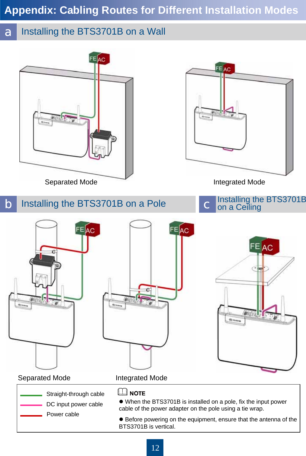
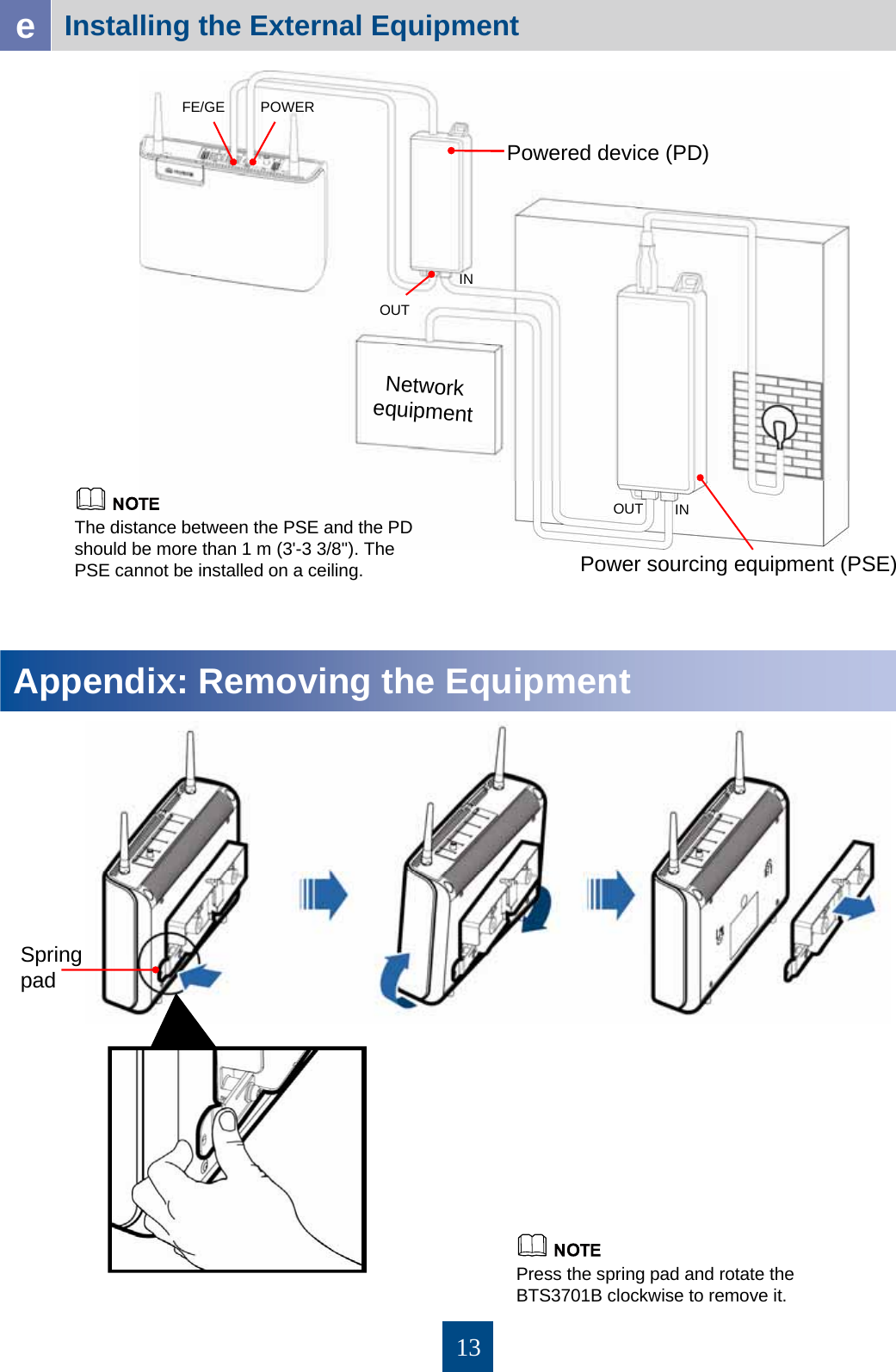
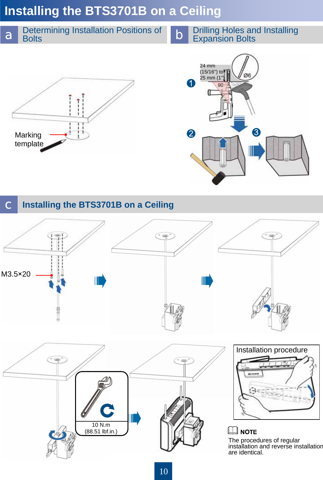
Installation Guide
Navigation menu
Upload a User Manual
Namespaces
Wiki Guide
HTML
PDF
Info
Views
User Manual
Discussion / Help
Navigation
![11Connecting CablesThe other end is connected to the power adapter. PWR port on the BTS3701B 4-pin connector DC input power cable Connected to...ConnectorCablePower adapterC7 female connector AC power wiring bar PA male connectorPower cableOperator's transmission equipment RJ45 connectorFE/GE port on the BTS3701B RJ45 connectorStraight-through cable If the delivered Ethernet cable [3 m (9'-10 1/8'')] does not meet the requirement, prepare one on site based on actual requirements. 4-pin connector of the DC input power cable Powering On the BTS3701BConnect the PA male connector to the AC power wiring bar to power on the BTS3701B. An alarm is generated, and the BTS3701B needs to be replaced. On (red) The FE port is insecurely connected. Off Data is being transmitted and received over the FE port. Blinking at 4 Hz (green) (on for 0.125s, off for 0.125s) The FE port is securely connected. On GreenLINKAn alarm is generated. Rectify the fault based on the reported alarm. Blinking at 0.5 Hz (red) (on for 1s, off for 1s) The BTS3701B is being loaded, or the BTS3701B is not started. Blinking at 4 Hz (green) (on for 0.125s, off for 0.125s) The BTS3701B is running normally. Blinking at 0.5 Hz (green) (on for 1s, off for 1s) Red and green RUN/ALMThere is no power supply, or the BTS3701B is faulty. Off The power supply is normal. On GreenPowerDescriptionStatus ColorIndicator](https://usermanual.wiki/Huawei-Technologies/BTS3701B-2500M/User-Guide-1357612-Page-12.png)